Embed Size (px)
DESCRIPTION
artículo
Citation preview

VOLUME XLIII NUMBER 6 379
Differential moments offer many advantages in orthodontic treatment, including simultaneous
correction of overbite and overjet, arch length, and Class II malocclusion. When force systems are designed with differential moments, however, they must be individualized using partial appliances. The application of force systems is based on wire-bracket angles, as discussed at length in a previous article (JCO, October 2008).
A full appliance with a center bend between the first molars and second premolars results in a force system consisting of equal and opposite moments at the brackets of those teeth (Fig. 1A). Because the wire-bracket angles are determined by the brackets (tubes) adjacent to the bend, reduc-ing the full appliance to a partial appliance by simply removing the canine and premolar brackets will convert the center bend to an off-center bend with no change in the archwire or the bend location (Fig. 1B). This new force system provides differ-ential moments.
Round Wire
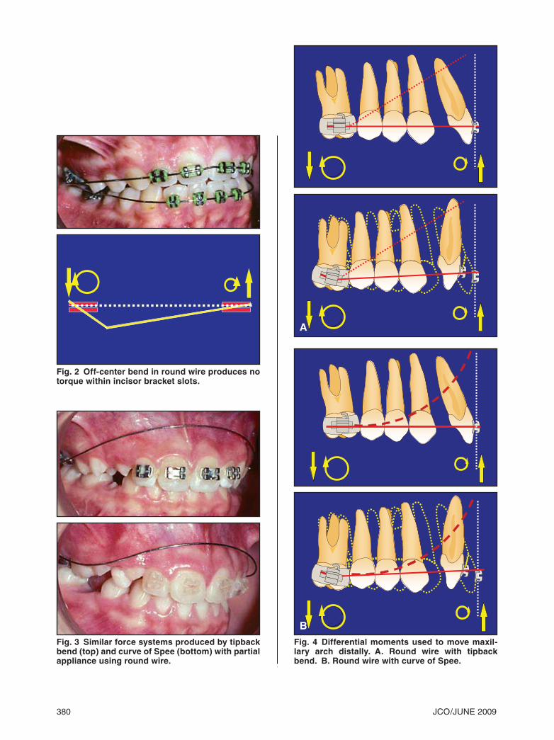
When a round wire is used, the off-center bend produces moments in the same direction within the same plane of space. A moment in the opposite direction is created at the incisor brackets, because a round wire produces no torque within the incisor bracket slots (Fig. 2). The labial crown moment is
created by an intrusive force acting labial to the center of resistance of the incisor segment.
A round wire with a tipback bend and a round wire with a curve of Spee produce similar force systems, with differences of little or no clinical significance (Fig. 3). When a tipback bend is created using round wire, the maxillary arch moves distally because of the differential moments, despite the labial crown moment in the anterior segment (Fig. 4A). The molar moments are sig-
© 2009 JCO, Inc.
The Advantages of Differential MomentsTHOMAS F. MULLIGAN, DDS, MSD
Dr. Mulligan is in the private practice of orthodontics at 717 W. Glendale Ave., Phoenix, AZ 85021; e-mail: [email protected]. This article is adapted by per-mission from his book, Common Sense Mechanics in Everyday Orthodontics II (CSM Publishing, 1040 E. Osborn Road, Phoenix, AZ 85014).
Fig. 1 A. Full appliance with center bend between first molars and second premolars. B. Removal of canine and premolar brackets to convert center bend to off-center bend.
A
B
©2009 JCO, Inc. May not be distributed without permission. www.jco-online.com
380 JCO/JUNE 2009
Fig. 2 Off-center bend in round wire produces no torque within incisor bracket slots.
Fig. 3 Similar force systems produced by tipback bend (top) and curve of Spee (bottom) with partial appliance using round wire.
Fig. 4 Differential moments used to move maxil-lary arch distally. A. Round wire with tipback bend. B. Round wire with curve of Spee.
A
B
VOLUME XLIII NUMBER 6 381
Mulligan
nificantly larger. A round wire with a curve of Spee creates essentially the same force system (Fig. 4B).
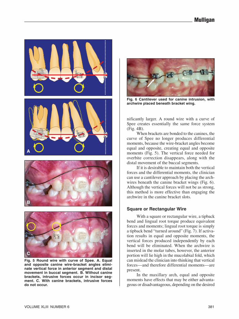
When brackets are bonded to the canines, the curve of Spee no longer produces differential moments, because the wire-bracket angles become equal and opposite, creating equal and opposite moments (Fig. 5). The vertical force needed for overbite correction disappears, along with the distal movement of the buccal segments.
If it is desirable to maintain both the vertical forces and the differential moments, the clinician can use a cantilever approach by placing the arch-wires beneath the canine bracket wings (Fig. 6). Although the vertical forces will not be as strong, this method is more effective than engaging the archwire in the canine bracket slots.
Square or Rectangular Wire
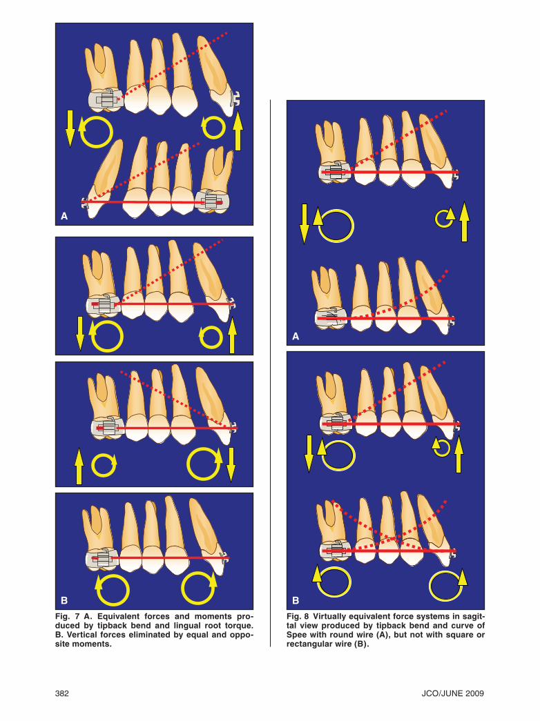
With a square or rectangular wire, a tipback bend and lingual root torque produce equivalent forces and moments; lingual root torque is simply a tipback bend “turned around” (Fig. 7). If activa-tion results in equal and opposite moments, the vertical forces produced independently by each bend will be eliminated. When the archwire is inserted in the molar tubes, however, the anterior portion will lie high in the mucolabial fold, which can mislead the clinician into thinking that vertical forces—and therefore differential moments—are present.
In the maxillary arch, equal and opposite moments have effects that may be either advanta-geous or disadvantageous, depending on the desired
Fig. 6 Cantilever used for canine intrusion, with archwire placed beneath bracket wing.
Fig. 5 Round wire with curve of Spee. A. Equal and opposite canine wire-bracket angles elimi-nate vertical force in anterior segment and distal movement in buccal segment. B. Without canine brackets, intrusive forces occur in incisor seg-ment. C. With canine brackets, intrusive forces do not occur.
A
B
C
382 JCO/JUNE 2009
Fig. 7 A. Equivalent forces and moments pro-duced by tipback bend and lingual root torque. B. Vertical forces eliminated by equal and oppo-site moments.
Fig. 8 Virtually equivalent force systems in sagit-tal view produced by tipback bend and curve of Spee with round wire (A), but not with square or rectangular wire (B).
A
A
B B

VOLUME XLIII NUMBER 6 383
Mulligan
results in each individual case. These effects include maintenance of the anteroposterior tooth positions, vertical correction of the anterior teeth, and control of the occlusal plane. Unequal moments can be used to improve Class II and Class III mal-
occlusions, correct overbite and open bite, modify the occlusal plane, and increase arch length.
It may be difficult to determine which force systems are present with various configurations of round, square, and rectangular archwires. For
Fig. 9 Square or rectangular wire force system altered by adding lingual root torque and tipback bend.
Fig. 10 Unexpected force systems produced by square or rectangular archwires.

384 JCO/JUNE 2009
The Advantages of Differential Moments
example, the tipback bend and curve of Spee pro-vide almost identical force systems from the sagit-tal view with a round wire, but not with a square or rectangular wire (Fig. 8). With a square or rectangular wire, the addition of lingual root torque and a tipback bend alters the force system (Fig. 9). Thus, a square or rectangular wire can produce unexpected force systems (Fig. 10). The tipback bend or curve of Spee can be used in “bypass” archwires (Fig. 11). A full appliance eliminates differential moments, while vertical forces are initially absent (Fig. 12). Some of the force systems illustrated here may be only visu-ally confusing, while others are actually different because of differences in the wire cross-sections. A simpler approach is needed for orthodontic treat-ment planning.
Fig. 11 Tipback bend and curve of Spee used in square or rectangular “bypass” archwires.
Fig. 12 Differential moments eliminated by full appliance, with no vertical forces.

VOLUME XLIII NUMBER 6 385
Mulligan
A Simpler Approach
A moment is the product of force and dis-tance; it results from forces directed away from the center of resistance or mass. To understand rotation, it is important to remember that one-half the force times twice the distance produces the same moment as one-half the distance times twice the force. In other words, doubling either the force or the dis-tance results in a moment of the same magnitude. This affords the clinician the opportunity to mini-mize force magnitudes by using partial appliances with relatively large interbracket distances.
The development of the typical archwire-
force system of an appliance can be visualized as a seven-step process (Fig. 13):
1. Tipback bend.2. Archwire activation.3. Perpendicular distance from the activational force to the center of resistance of the molar.4. Perpendicular distance from the deactivational force to the center of resistance of the incisors.5. Resulting forces and moments on the molar.6. Resulting forces and moments on the incisor.7. Overall force system.
(continued on next page)
Fig. 13 Development of force system (round archwire). A. Tipback bend. B. Activational force. C. Distance to molar center of resis-tance. D. Deactivational force. E. Molar forces and moments. F. Incisor forces and moments. G. Overall force system.
A B C
D E F
G
386 JCO/JUNE 2009
The Advantages of Differential Moments
Conclusion
In orthodontic mechanics, moments may be equal or unequal. Each system has advantages and disadvantages, depending on the type of tooth movement desired. Unequal moments result in balancing forces; because one moment is greater than the other, a net moment is produced. This dif-ference in magnitude can be used strategically for the treatment of various orthodontic problems.
Considerable confusion exists regarding the total force system present in any given case because of variations in interbracket distances, cross-sec-tional configurations, use of full vs. partial appli-ances, location of activating bends, and so on. The simplified system presented here can be used to design the force systems required for overbite cor-
rection, distal movement of the buccal segments, control of the occlusal plane, and increases in arch length, among other movements. This approach can be used routinely without the need for expen-sive wires or specially trained chairside assistants. Moreover, by avoiding dependence on archwire shape to determine tooth movements, the clinician can reduce the risk of undesirable side effects.
SUGGESTED READING
Hart, A.; Taft, L.; and Greenberg, S.N.: The effectiveness of differ-ential moments in establishing and maintaining anchorage, Am. J. Orthod. 102:434-442, 1992.
Mulligan, T.F.: Common Sense Mechanics Office Course, Phoenix, AZ, 2008.
Mulligan, T.F.: Common Sense Mechanics, CSM Publishing, Phoenix, AZ, 1982, pp. 50-59.