Embed Size (px)
Citation preview
SELENIUM RECTIFIER
6.3 V
I . 0 AMP
1,200 OHMS
20 MFD
15C V
1,000 MM'D
+ 20 MFD
T150 V
1,000 MMFD
AO MMFD
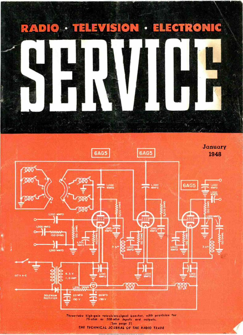
e-fObe high -gain -elevie'orsignal booster, rouis for 75 -ohm ar 300-iPrn inputs and outputs.
See page 21
THE TECHNICAL JC JRNAL OF THE RADIO TRADE
1,000 MMFD
January 1948
www.americanradiohistory.com
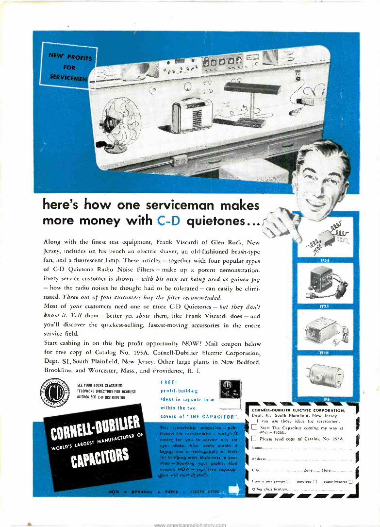
here's how one serviceman makes more money with C -D quietones... Along with the finest test equipment, Frank Viscardi of Glen Rock, New Jersey, includes on his bench an electric shaver, an old-fashioned brush -type fan, and a fluorescent lamp. These articles - together with four popular types of C -D Quietone Radio Noise Filters - make up a potent demonstration. Every service customer is shown - with his own set being used as guinea pig - how the radio noises he thought had to be tolerated - can easily be elimi- nated. Three out of four customers buy the filter recommended. Most of your customers need one or more C -D Quietones - but they don't know it. Tell them - better yet shoe' them, like Frank Viscardi does - and you'll discover the quickest -selling, fastest -moving accessories in the entire service field.
Start cashing in on this big profit opportunity NOW! Mail coupon below for free copy of Catalog No. 195A. Cornell-Dubilier Electric Corporation, Dept. Si, South Plainfield, New Jersey. Other large plants in New Bedford, Brookline, and Worcester, Mass., and Providence, R. I.
ó s
SEE YOUR LOCAL CLASSIFIED
TELEPHONE DIRECTORY FOR NEAREST
AUTHORIZED CD DISTRIBUTOR
. CORHELLpUBIL1ER
YJORID'S LARGEST
MANUFACTU RER OF
t I PAC1t0Rs
FREE!
profit -building
ideas in capsule form
within the two
JD;
covers of "THE CAPACITOR".
fished for szrvicemen - makes it easier for you to service any set
ever made. Also, every month it.
brings you a fresh supply of hint: for bringing more customers to you shop - boosting your profits. Mot coupon NOW - your free subscrip- tion will start of once;
DYKANOL PAPER ELECTROLYTIC
rMi. NELL-DUBILIER ELECTRIC CORPORATION, t. Si, South Plainfield, New Jersey
I can use those ideas for setvicemen. Start The Capacitor coming my way at once- FREE.
IDPlease send copy of Catalog No. 195A.
Name
IIIAddress
City Zone State
1 ama serviceman amateur experimenter El
Other classification
www.americanradiohistory.com

aoarsfs play their radios long and hard
.. buy plenty of tubes, parts, and repair time .. will patronize your shop once they see the G -E monogram
RADIO TUBES
DON'T begrudge 'em their fun. It's the last fling before demure seventeen, stu-
dious nineteen, and engaged twenty-one .. Jive aside, they're smart kids-and loyal.
When they buy, it's with an eye to estab- lished reputation.
General Electric? Natch! ... Brought up in homes bright with G -E lamps, where
breakfast toast-when they take time to eat t it-jumps up out of a G -E toaster, where
food stays fresh in a G -E refrigerator, time is kept by G -E electric clocks, and G -E fans I
hum softly in summer ... these youngsters know the familiar G -E monogram as a
friend to be trusted.
Their radio tube and repair business- plenty of it in your area!-goes to the service-
man with the General Electric sign. And years from now they'll still be customers.
Only with larger home sets, meaning a big- ger service potential. Start now to make
these clients -of -tomorrow patrons of your
shop. Display and handle General Electric radio tubes! General Electric Company, Elec-
tronics Department, Schenectady 5, New York.
G -E miniatures, other tubes of all types
for servicing portables and home re-
ceivers are listed, rated, and described
in G.E.'s complete Tube Characteristics
Booklet ETR-15. Write for your free copy.
ELECTRIC FIRST AND GREATEST NAME IN ELECTRONICS
SERVICE, JANUARY, 1948 1
www.americanradiohistory.com

RADIO TELEVISION ELECTRONIC Vol. 17, No. I
LEWIS WINNER Editorial Director
Association News
SERVIC
January, 1948
F. WALEN Assistant Editor
111111,1
ALFRED G. GHIRARDI Advisory Editor
Page
26
At the Philadelphia Town Meeting of Radio Technicians. By Lewis Winner 9
F -M Antenna Transmission Lines. By Les GrafFis
How the 'Scope Works. By Alvin A. Baer
Replacing the Output Transformer. By Frederick E. Bartholy. Ser -Cuits
Servicing Helps. By Charles P. Elliott
Signal Booster for TV (Cover)
Ten Years Ago in Associations
IO
12
14
22
28
40
26
Your Success in Sound. By Robert Newcomb 25
TV Receiver Video Amplifiers. By Edward M. Noll 16
Tube News. By L. E. Stewart 40
CIRCUITS
Admiral 7C73 22
Hearing -Aid Circuits 40
Mixer -Input Systems 48
Temco Telebooster (Cover) 4C
COVER
3 -Stage R -F TV Signal Booster (Temcol 40
SERVICING HELPS
Mixer Inputs for Low and High Impedances, Twin Triodes and 2 to 8 Inputs 28
Index fo Advertisers 48
Manufacturers
News 38
New Products 41
Jots and Flashes 48
Entire contents Copyright 1948, Bryan Davis Publishing Co.. Inc.
Published monthly by Bryan Davis Publishing Co., Inc. 52 Vanderbilt Avenue, New York 17, N. Y. Telephone MUrray Hill 4-0170
Bryan S. Davis, President Paul S. Weil, Vice Pres.-Gen. Mgr. F. Walen, Secretary A. Goebel, Circulation Manager
Cleveland Representative: James C. Munn, 2253 Delaware Dr., Cleveland 6, Ohio. Telephone: Erieview 1726
Pacific Coast Representative: Brand & Brand, 1052 W. Sixth St., Los Angeles 14, Calif. Telephone Michigan 1732 315 Montgomery St., San Francisco 4. Calif. Telephone Douglas 4475
Entered as second-class matter June 14, 1932, at the Post Office at New York, N. Y., under the Act of March 3, 1879. Subscription price: $2.00 per year in the United States of America and Canada; 25 cents per copy. $3.00 per year in foreign countries; 35 cents per copy.
2 SERVICE, JANUARY, 1948
www.americanradiohistory.com

; .1
100 100 0 t tg0 lere i00
Actual Laboratory Measurements Mode With The Conventional Type Filter Circuit A - (Swinging and Smoothing System) - and with the New Universal Choke Filter Circuit 8 Show A Decrease In Ripple Throughout The Useful Current Range of Power Supply
For Matched Power Supplies, see Your New 400GX Catalog Now Available. Furnished Free Upon Request.
Export - Scheel International Inc. 4237-39 Lincoln Ave. Chicago 18, III.
Cable - (Horscheel)
THE MOST RADICAL IMPROVEMENT.... IN POWER SUPPLY FILTER CIRCUITS...
... employing two same type universal
chokes that provide more efficient filtering.
Here again, is another triumph in Thordarson engineering skill.
Thordarson engineers have developed a new universal type
choke in sizes to meet all power requirements! This achievement
offers the best possible filtering and regulation in a minimum size
consistent with conservative design! One reactor may be used in
a single section filter with all the advantages of the radically
swinging type. Two similar units may be employed in a two
section filter more satisfactorily than the obsolete "swinging and
smoothing" system, and deliver far better performance.
Let us know how we can put these new universal chokes
to work for you... Send us your requirements.
TIIORDARSON Manufacturing Quality Electrical Equipment Since 1895
500 WEST HURON CHICAGO 10, ILLINOIS A Division of Maguire Industries
SERVICE, JANUARY, 1948 3
www.americanradiohistory.com
Sí9t od seiceeded Seíc4ig NELSON HAS ALL
(6 RIDER MANUALS D
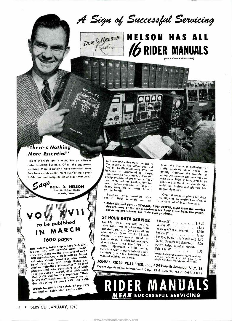
There's Nothing More Essential" "Rider Manuals are a must, for an efficient
rodio servicing business. Of all the equipment
we have, there is nothing more essential, more
free from obsolescence, more everlastingly prof-
itable than our complete set of Rider Manuals."
et DON. D. NELSON Don. D. Nelson Rodio
Seattle, Wash.
This volume, taking up where Vol. XVI
leaves off, will contain authorized*
servicing data on the products of over
100not
only band but tll also multi -
band
e
not single receivers with their RidRecord
clusive "clarified -schematics."
players and wire recorders used with
receivers are covered. selso orwith' "How
each
Vol. will be cumulative in -
ate
It Works" book and a
dex covering Volumes XVI and XVII.
Watch for publication dote of separate
manual on Television exclusively.
In towns and cities from one end of the country to the other you will find all 16 Rider Manuals over the benches of profit -making shops. This, because they earned that fin- gertip position of prominence. They are there, not for display, but for use - not on occasion, but for prac- tically every job that comes to rest on the bench.
Nowhere else, nowhere else but in Rider Manuals can be
(and Volume XVII on order)
found the wealth of authoritative' radio servicing data needed to quickly diagnose the troubles in ailing American -made receivers. is- sued since 1920. Volume XVII to be published in March will contain ma- terial that is time-savingly-valuable to you right now.
Order it today_. give your shop the Sign of Successful Servicing, a * Rider Manual data is OFFICIAL
complete set of Rider Manuals. departments of the set , AUTHORIZED, right from the service servicing procedures fort their own prers.
They know best, the products, proper 24 HOUR DATA SERVICE For 10c (stamps are OK) you re- ceive photostats of schematic, volt- age data, parts list (and everything else that will fit on two 8 x 11 inch sheets) on any newly issued, or old, receiver. (Additional necessary sheets same rate.) Send 20c with order, adjustment will be made. Here is a way to get whatever serv- ice data you need between Rider Manual publication dates.
. 1.50 NOTE: Individual Volumes VI, VII and VIII will be replaced after this year by a single Abridged
JOHN F. RIDER PUBLISHER, Inc., 404Fourth Manual
Vol. vi ,a VIII.
Export Agent: Rocke International Corp.,vY.0 Y. P 13 E. 40th St.. N.Y.C. Cabllee AR
Volume XVI
Volume XV . e $ 8.40
18.00 Volumes XIV to VII (ea. vol.) . 15.00 Volume VI Abridged Manuals Ito V (one vol.)17.50 Record Changers and Recorders 9.00 Master Index, covering Manuals, Vols. I to XV
RIDER MANUALS MEAN SUCCESSFUL SERVICING
4 SERVICE, JANUARY, 1948
www.americanradiohistory.com

SERVICING by SIGNAL SUBSTITUTION The Modern, DYNAMIC, Speed Approach to radio
Net Price $1 23.40
A Reliable Tube Tester ... A High sensitivity Circuit Tester such as the NEW Precision
Series 10-54 Electronamie Test .Master Combination Master Electronamic Tube Performance Taster, Battery Tester and 35 Range, Push -Button Operated, Supersenittrve Set Tester.
TUBE TESTING HIGHLIGHTS * Features the Precis on "Electronamic" circuit - the all-inclusive,
single -operation, positive, vacuum -tube Perform i :e Test. * 12 Element Central Lever Selector System affords iighest prac- tical order of obsolescence insurance. * Absolute Free -Point element short -check and performance test selection regardless of varying or multiple pin and cap terminations. * Employs standard tube basing numbering system on all element selectors, permitting most simplified operation art comprehen- sion of test results.
CIRCUIT AND BATTERY TESTING HIGHLIGHTS * 35 A.C. and D.C. ranges to 6000 volts, 60 microamperes, 12
amperes, 70 DB, 60 megohms. * 20,000 ohms per volt D.C., 1,000 ohms per volt A.C. * High speed, positive, double -wiping contact, push-button selec-
tion of ranges. * All standard ranges at Only Two polarized tip jacks. * Tests all standard radio A, B and C batteries under dynamic
load conditions, simulating actual performance.
NEW 9th edition of "Servicing by Signal
Substitution" NOW OFF THE PRESS! Furnished FREE with the Series E -200-C Signal Generator.
Also available from Precision distributors or factory at nominal
cost of 40a per copy. The signal generator is more thon merely
an alignment tool. S -S -S tells how - in simple, direct terms.
9 Export Division: 458 BROADWAY, NEW YORK CITY, U. S. A. Cables MORHANEX
92-27 HORACE HARDING BOULEVARD, ELMHURST 6, N. Y.
receiver alignment and adjustment problems.
Requires nothing complex to learn
Is Universal-non-obsolescent Does not require costly,
extraneous apparatus Employs only BASIC TEST
EQUIPMENT-as is absolutely necessary for the conduct of up-to-date radio service technique.
Net Price $64.15
A Stable, Accurate Source of R.F. Signals
such as the NEW Precision Series E -200-C Wide Range Signal Generator
* Direct Reading Frequency coverage 88 KC to 120 MC for A.M., F.M. and T.V. alignment (absolute fundamentals to 30 MC).
* 1% Accuracy on all bands. Precision "Unit -Oscillator" construction. * 6V2" etched aluminum, no -glare dial. Approximately 8 ft. of
scale length. * Built-in, direct reading A.V.C. Substitution network - overcomes
A.V.C. incurred tuned circuit resonance shift. * Specifically designed for Servicing by Signal Substitution.
Instead of Series 1C-54 combination Test -Master, identical application is obtainable via use of Series 10-12 or 10-15 Tube Master and the Series 858 Multi -Maser.
PRECISION APPARATUS COMPANY
"Precision" Master Elec-
is see the on dis -
,Q.,, tronamic Test Instruments now
ond
at all leading radio parts he
equipment distributors, or write directly for
48 catalog fully describing
tube performance test -
new Precision 19
Precision Electronamic
i circuit.
SERVICE, JANUARY, 1948 5
www.americanradiohistory.com
l'aámaice `bests P7oue
that FEATURE for FEATURE
AIR King WIRE RECORDER
PHONO -COMBINATION
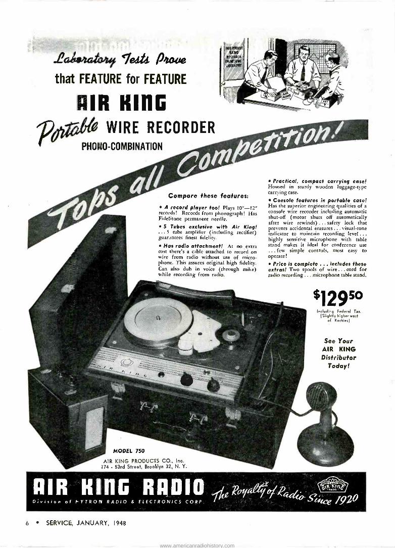
Compare these features:
A record player too! Plays 10"-12" records! Records from phonograph! Has Fidelitone permanent needle.
5 Tubes exclusive with Air King! 5 tube amplifier (including rectifier)
guarantees finest fidelity.
Has radio attachment! At no extra cost there's a cable attached to record on wire from radio without use of micro- phone. This assures original high fidelity. Can also dub in voice (through mike) while recording from radio.
MODEL 750
AIR KING PRODUCTS CO., Inc. 174 - 53rd Street, Brooklyn 32, N. Y.
Practical, compact carrying easel Housed in sturdy wooden luggage -type carry ing case.
Console features in portable case! Has the superior engineering qualities of a
console wire recorder including automatic shut-off (motor shuts off automatically after wire rewinds) ... safety lock that prevents accidental erasures... visual -tone indicator to maintain recording level... highly sensitive microphone with table stand makes it ideal for conference use ... few simple controls, most easy to operate!
Price is complete ... includes these extras! Two spools of wire... cord for radio recording ... microphone table stand.
929° Including Federal Tar.
(Slightly higher west of Rockies)
See Your AIR KING Distributor
Today!
AIR HING RADIO Pe q Division of hYTROIY RAD10 & ELECTRONICS CORP. lA 1920
6 SERVICE, JANUARY, 1948
www.americanradiohistory.com
1'
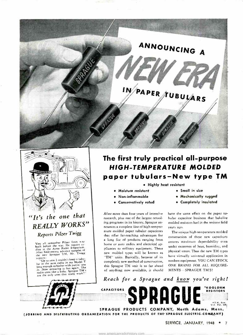
"It's the one that
REALLY WORKS" Reports Pilzer Twigg
You all remember Pilzer from way
back before the war. He repairs ra-
dios at the Acme Radio Emporium.
After fieldtesting advance samples of
the new Sprague TM, Mr. Twigg
reports: "Up to now I couldn't keep a tubu-
lar in the auto radio in my Model T
long enough to bother with puttin' one
in. Now motoring is fun again. The
radio coos like a baby. Sprague TM's
are the only ones that really work!
{JOBBING AND DISTRIBUTING
The first truly practical all-purpose HIGH -TEMPERATURE MOLDED
paper tubulars-New type TM Highly heat resistant
Moisture resistant
Non -inflammable
Conservatively rated
After more than four years of intensive research, plus one of the largest retool- ing programs in its history, Sprague an- nounces a complete line of high -temper- ature molded paper tubular capacitors that offer far-reaching advantages for a long list of products ranging from home or auto radios and electrical ap- pliances to military equipment. These new molded types will be known as
"TM" units. Basically, because of its completely new method of construction, this Sprague TM unit is so far ahead of anything now available, it should
Small in size
Mechanically rugged
Completely insulated
have the same effect on the paper tu- bular capacitor business that bakelite molded resistors had in the resistor field
years ago.
The unique high -temperature molded construction of these new capacitors assures maximum dependability even under extremes of heat, humidity, and physical stress. Thus the new TM types have virtually universal application in modern equipment. YOU CAN STOCK ONE BRAND FOR ALL REQUIRE- MENTS-SPRAGUE TM'S!
Reach for a Sprague and know you're right!
CAPACITORS RESISTORKOOLOHS
T. M. Reg
1
j U.S. Pat. OSi
SPRAGUE PRODUCTS COMPANY, North Adams, Mass. ORGANIZATION FOR THE PRODUCTS OF THE SPRAGUE ELECTRIC-COMßHY)
SERVICE, JANUARY, 1948 7
www.americanradiohistory.com
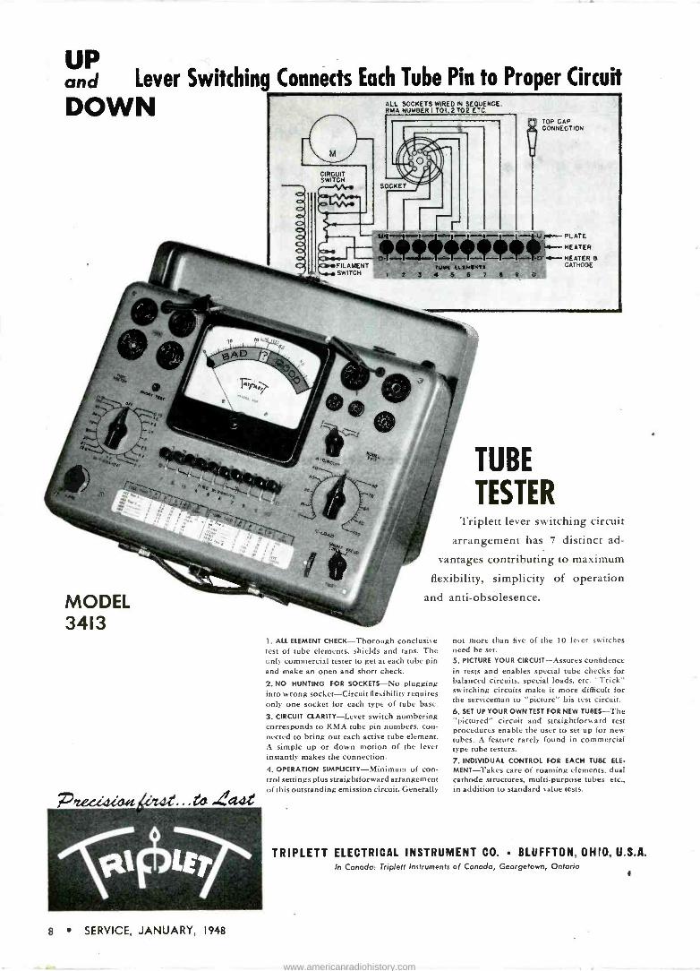
Each Tube Pin to UP and Lever Switching Connects ac Proper Circuit
DOWN
MODEL 3413
ALL SOCKETS WIRED IN SEQUENCE. RMA NUMBER I T01,2 T02 ETC
TOP GAP CONNECTION
o ell,111 Kr..... HEATER
3.t- HEATER a Tuac ucletro a CATHODE
1 2 3 4 5 5 7 4 9 0
TUBE
TESTER Triplett lever switching circuit
arrangement has 7 distinct ad-
vantages contributing to maximum
flexibility, simplicity of operation
and anti-obsolesence.
1. ALL ELEMENT CHECK-Thorough conclusive test of tube elements, shields and taps. The only commercial tester to get at each tube pin and make an open and short check.
2. NO HUNTING FOR SOCKETS-No plugging into wrong socket-Circuit flexibility requires only one socket for each type of tube base.
3. CIRCUIT CLARITY-Lever switch numbering corresponds to RMA tube pin numbers, con- nected to bring out each active tube element. A simple up or down motion of the lever instantly makes the connection.
4. OPERATION SIMPLICITY-Minimum of con- trol settings plus straightforward arrangement of this outstanding emission circuit. Generally
not more than five of the 10 lever switches need be set.
5. PICTURE YOUR CIRCUIT-Assures confidence in tests and enables special tube checks for balanced circuits, special loads, etc. "Trick" switching circuits make it more difficult for the serviceman to "picture" his test circuit. 6. SET UP YOUR OWN TEST FOR NEW TUBES-The "pictured" circuit and straightforward test procedures enable the user to set up for new tubes. A feature rarely found in commercial type tube testers.
7. INDIVIDUAL CONTROL FOR EACH TUBE ELE-
MENT-Takes care of roaming elements, dual cathode structures, multi -purpose tubes etc.. in addition to standard value tests.
TRIPLETT ELECTRICAL INSTRUMENT CO. BLUFFTON, OHIO, U.S.A. In Canada: Triplett Instruments of Canada, Georgetown, Ontario
8 SERVICE, JANUARY, 1948
www.americanradiohistory.com

I I I I I I I I I I 111111 I I I! 11111111111111111111111111111111111111111111111111111111111111111111111111111111111111111111111111111111111111
RADIO TELEVISION ELECTRONIC
ERVIC Uli lllllllllllllllllìllllll!Illi!IUI!Ilu ll!Illlulllllllllilllll!qlld;iilllllid,!Ili',,;IIIIIIIIIIIIIIIIII!III "' " il
AT THE PHILADELPHIA TOWN MEETING OF TECHNICIANS
THE FIRST OF THE SERVICING BUSI-
NESS -TECHNICAL clinics, held in Phila- delphia in January, which may serve as the basis of nationwide meetings, proved to be quite a show. In a two- day crowded program, some twenty specialists thoroughly covered a variety of business and technical problems.
The Program
The president of the Charter Bank of Philadelphia. Ralph Pitman.. ana- lyzed the vital subject of bank credit, telling how to build it, use it and treat it. Then Charles Toewe, a cer- tified public accountant with Main and Co., told the boys about money and how to keep it. The fairness of bills to the technician and customer was the subject of a talk by Philip G. Zink, Jr., a certified public accountant with Wolf & Co. The vice chairman of the electrical group, National Credit Men's Association, Charles Abell, revealed some very vital information in a talk on "How and When to Collect and Pay Your Bills."
Advertising was also treated quite effectively in two talks. Harry P. Bridge, of Harry P. Bridge Co., dis- closed ways and means of using ad- vertising, and David Arons, publicity director of Gimbel Brothers, covered the all-important subject of public rela- tions versus purse relations.
Television and f -m were featured topics in the technical talks. John A. Meagher of RCA Service Co., covered the subject in two talks; one on tv service in the home with elementary test equipment and another on align- ment procedures for tv and f -m. Robin D. Compton, chief engineer of WCAU- TV, gave the boys some practical pointers on how to install a television set in the home with hints on the kind of instruction to give the cus- tomer. Television servicing in the shop was the subject of another talk by Ray Robinson of Philco. Mr. Robinson also covered the subject of'antenna in- stallation and adjustment in another presentation.
Two engineers from Philco, James Russel and John Pell, analyzed f -m, r -f and i -f systems and r -f conversion systems.
A series of four papers on testing, prepared by John F. Rider and Howard W. Sams, were presented by
members of the Temple University Technical Institute staff ; Matthew Mandl, lecturer in electronics, pres- ented a paper on signal tracing; Edward M. Noll, who is currently writing a series of articles on televi- sion for SERVICE, and who is a lecturer in television, electronics and technical writing at Temple, offered a discussion on cathode-ray oscilloscopes; Fred Kierstead, lecturer in electronics and television, covered signal sources, r -f and audio; and Arthur L. Hatton, lecturer in radio and electronics, pres- ented the paper on voltage, capacity and resistance measuring devices.
The keynote address of the meeting was made by Max F. Balconi, RMA president. He pointed out that the meeting was an encouraging sign that those in servicing are vitally interested in doing something about a problem, a very important problem of setting up standards of operation which will instill confidence in the entire pro- fession.
"I don't need to tell you men," he
said," that the day when a handy man about the house could fix a radio with a screw driver and a pair of
pliers has passed. Proper servicing requires more skill, greater familiarity with various types of test equipment and more technical know-how than ever."
`'The technician is an extremely im-
portant representative of industry and
In This Issue
F -M Antenna Transmission Lines. Prac- tical data on various types of lines used as f -m leadins ; page 10.
TV Receiver Video Amplifiers. Circuits used in current receivers; page 16.
Test Equipment. An illuminating article on how the 'scope -works ; page 12.
Audio. Simplified procedures that can be used to replace output transformers ;
page 14.
Management. Achieving success in sound today ; page 25.
Sound Systems. Lucid analysis of various types of mixer inputs and how to use them ; page 28.
F -M Receivers. Circuit highlights ;
page 22. Tube News. Data on hearing aid tubes,
plus a classified tube chart ; page 20.
Association News. Round -up of the latest news in associations; page 26.
dealer," he continued. "Going into the home to repair equipment, he comes in
more direct contact with the consumer than anyone else. By his actions he is
able to build up or undermine public confidence in the industry and its prod- ucts. I think, perhaps, all of us have been guilty of underestimating the im- portance of the technician in industry public relations, and our present ef-
forts should be only the first step in
rectifying this mistake." The town meeting, which was spon-
sored by the Radio Parts Industry Co- ordinating Committee, Electronic Parts &
Equipment Manufacturers, NEDA, RMA and Sales Managers Club, Eastern Divi- sion, was also suported by ten distributors in Philadelphia and the Mid-Lantic chap- ter of the Representatives. Cooperating with these groups were the Philadelphia Radio Servicemen's Association and the Federation of Radio Servicemen's Asso- ciations of Pennsylvania.
The importance of the radio technician was also stressed by W. L. Parkinson, of General Electric, who is chairman of the RMA Service Committee. He pointed out that RMA will work very closely with the technician to promote their usefulness to the industry and the consumer. A definite plan is being formed now and will be announced within the next fe.w weeks.
The clinic meetings were proceded by an interesting one -day session of the Federation of Radio Servicemen's Asso- ciations of Pennsylvania during which delegates of Pennsylvania servicing asso- ciations and associations in ten other states were present. Some 22 organiza- tions were represented, covering the ac- tivities of over 3,000 men.
The group prepared a resolution for presentation to the RMA as a guide in setting up a coordinating public relations program for the Servicing industry. A new code of ethics was also prepared, which said in part :
"I will at all times, without any exceptions. perform my work to the very best of my knowledge and ability. In addition, I will make a sincere effort to improve my knowledge of the technical and business requirements of my profession, thereby enabling me to render still better radio -electronic service.
"I will, whenever practicable and desirable. prefer to use original factory replacement parts. In other cases, I will use replacement parts known to be of equal or better quality. thus insuring satisfactory performance.
"I will engage only in fair and ethical prac- tices recommended and approved by the radio - electronic technicians' profession as being con- ducive to public confidence."
The industry, technician and consumer can't help but benefit from clinic sessions of this type. We hope there will be more meetings in other cities and very soon !
Highlights of the technical and business papers presented at the sessions will ap- pear in February. Watch for them.-L. W.
SERVICE, JANUARY, 1948 9
www.americanradiohistory.com
L a
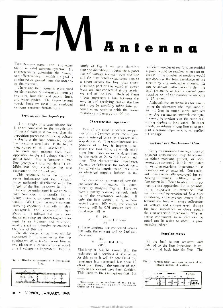
THE TRANSMISSION LINE is a major factor in v -h -f antenna systems. Its characteristics determine the manner and effectiveness in which a signal is conducted or guided from the antenna to the receiver.
There are four common types used for the transfer of r -f energy, namely: two -wire, four -wire and coaxial lines, and wave guides. The two -wire and coaxial lines are most often employed in home receiver installations.
Transmission Line Impedance
If the length of a transmission line is short compared to the wavelength of the r -f voltage it carries, then the opposition presented to this r -f voltage is chiefly at the load connected across the receiving terminals. If the line is long compared to a wavelength, the line itself may present even more opposition to the r -f voltage than the actual load. This is because a long line (compared to a wavelength) ex- hibits not only resistance hui also reactance to the flow of a -c.
This reactance is in the form of series inductance and shunt capaci- tance uniformly distributed over the length of the line, as shown in Fig. 1. This can be understood if we think of each conductor in a parallel line as being a simple air -core inductor un- wound. We know that every current - carrying conductor has both an elec- tromagnetic and electrostatic field about it. It follows that every con- ductor carrying an alternating -current must be an inductor and therefore. must present an inductive reactance to the flow of this a -c.
The distributed capacitance can be accounted for by considering the two conductors of a transmission line as two plates of a capacitor upon which an r -f voltage is impressed. From a
Fig. I. Distributed constants of a transmission Line.
Antenna study of Fig. 1 we note therefore that the distributed inductance opposes the r -f voltage transfer over the line and the distributed capacitance acts as a shunt across the line, thus short- circuiting part of the signal or power from the load connected at the receiv- ing end of the line. Both of these effects represent a loss between the sending and receiving end of the line and must be carefully taken into ac- count when working with the trans- mission of r -f energy at 100 mc.
Characteristic Impedance
One of the most important proper- ties of an r -f transmission line is com- monly referred to as its characteristic impedance', Z,,. The characteristic im- pedance of a line is important be- cause the load value at which mini- mum line losses occur is determined by the ratio of Z. to the load imped- ance. The characteristic impedance, Z0, may be defined as the impedance a line of infinite length would present to an electrical impulse induced in the line.
We can obtain a picture of how this characteristic impedance is deter- mined by studying Fig. 2. Here we have a purely resistive network made up of the resistances indicated. If only the first section, r, rn is con- nected across 100 volts, the current flowing will he 0.01 ampere and the resistance will be
E 100 I¿=-=-= 110 ohtn. 1 .91
if three sections are connected across 100 volts the current will be 2.06 am- peres and
100 R =- or 48.4 ohms
2.06
Similarly it can be shown that the resistance of 6 sections is 38.6 ohms. At this point it will be noted that the resistance has decreased less than 10 ohms even though the number of sec- tions in the circuit have been doubled. This leads to the assumption that if a
'Impedance is the resultant of the d -c re- sistive, inductive and capacitive components within an a -c circuit.
sufficient number of sections were added a point would be reached where an in- crease in the number of sections would not decrease the total resistance of the circuit by any noticeable amount. It can be shown mathematically that the total resistance of such a circuit com- posed of an infinite number of sections is 37 ohms.
Although the mathematics for calcu- lating the characteristic impedance of an r -f line is much more involved than this resistance network example, it should be evident that the same rea- soning applies to both cases. In other words, an infinitely long line must pre- sent a certain impedance to an applied r -f voltage.
Resonant and Non -Resonant Lines
Every transmission line regardless of physical construction may be 'classed as either resonant (tuned) or non - resonant (untuned). If it is terminated in its characteristic impedance it is non -resonant or untuned. Non -reson- ant lines are usually employed for re- ceiving antennas. Although a per- fect match is difficult to obtain in prac- tice, a close approximation is possible. It is important to remember that the line must be terminated in a pure resistance; a reactive component in the terminating load will cause reflections of voltage and current even though the load impedance in ohms equals the characteristic impedance. The re- active component in a load can be tuned out in order to obtain a pure resistive effect.
Standing Waves
If the load is not resistive and matched to the line impedance it re- flects signal back into the line. The
Fig. 2. Parallel -series resistance network of an infinite number of sections.
10 SERVICE, JANUARY, 1948
www.americanradiohistory.com

Transmission Lines Complete Analysis of Two -Wire And Coaxial Lines, With Data On Types
of Lines, Line Impedance, Characteristic Impedance, Resonant And Non -
Resonant Lines, Standing Waves, Quarter -Wave and Half -Wave Lines.
combination of the outgoing and re- elected signals produce what are com- monly referred to as standing waves or. the line. An r -f voltmeter may he used for measuring the voltage waves and an r -f ammeter inserted in
series with one conductor for meas- uring the current wave providing the line is carrying sufficient power to actuate a meter. An f -m antenna does not receive sufficient power when used for receiving purposes ; therefore, it is
i ecessary to couple an r -f voltage into the line from an r -f oscillator to meas- ure the standing waves. It is impor- tant to remember that even though the maximum and minimum points of the waves are stationary (as long as the load does not vary) that the actual voltage and current are alternating at the r -f frequency. There is no d -c
omponent of either voltage or current.
The presence of standing waves on transmission line indicate a mis-
match between the line and the load. If the load does not match the line the length of the line becomes critical. The ratio of mismatch is approxi- mately equal to the standing -wave ratio, providing there is little or no reactive component in the load im- pedance.
The standing -wave ratio = Ent In
where Ern- is the voltage at the peake of a wave and E.,» is the volt- age minimum. A standing -wave ratio less than 2 to 1 is to be desired for a satisfactory non -resonant line. For example, if an r -f voltmeter indicated a voltage peak of 12 volts and a volt- age minimum of 4 volts
12
the standing wave -ratio would = - 4
Fig. 3. Characteristics of line sections.
by LES GRAFFIS Staff Engineer
Service Division Bendix Radio
or 3 to 1. This indicates that the load impedance is either 3 times greater or 1/3 the characteristic impedance of the line.
Previously it was stated that the signal was reflected back along the line unless the load impedance equalled the line impedance and was purely resist- ive. Also, that the impedance presented to the r -f generator by the line, plus the load, equals the load impedance only when the two are matched. This suggests that a line terminated in other than its characteristic impedance might be used either as an impedance match- ing transformer, or as reactive (in- ductive or capacitive) elements in an r -f circuit.
If a line is terminated in a :hone circuit, there is no load resistance in which to dissipate the energy, there- fore, it is reflected back toward the r -f generator. The standing waves of voltage and current along the lire are 90° out of phase, which also indicates that no power is being dissipated. It
will be noted that a voltage mini- mum and a current maximum occur at the shorted end. This is logical since high current and low voltage are to be expected at a short.circuit.
If the line is terminated in an open circuit, the voltage and current loops are reversed and a voltage maximum and current minimum appears at the open circuit end. Again these are the conditions to be expected at an open circuit and indicate that no power is
radiated. The foregoing discussion dealt with
a line of specific length. It was em- phasized that location of the voltage and current maximums were deter- mined solely by the value of load im- pedance at the receiving end of the line. If a line is shortened by one - quarter wavelength the impedance seen by the generator will be reversed from a high to low impedance, or vice versa, as the case may be, regardless of whether the line is terminated in a
short or open circuit. A quarter -wave section of line, therefore, presents either a high impedance when shorted or a low impedance when open cir- cuited.
It is apparent that the characteris- tics of a quarter -wave section of line. are similar to a resonant circuit. For
LINE SECTION CHARACTER STICS
EQUIVALENT
CIRCUIT
1 T I
$ r
T f
LINE SECTION
h- I
1--<1--r
I
AN
1 4 1 4
LOOKS LIKE A
CAPACITOR LOOKS LIKE
INDUCTANCE LOOKS LIKE PARALLEL
RESONANT CIRCUIT LOOKS LIKE SERIES RESONANT CIRCUIT
I-' ' I
< 2 < 2 z 1--- 2 -I
SERVICE, JANUARY, 1948 I I
www.americanradiohistory.com
How The 'Scope Works by ALVIN A. BAER
Meybaer Radio New York City
Simplified Mechanical Analogy Used To Explain How The 'Scope Interprets A -C Waveforms, And Projects Their Picture On The Tube Screen
WITH THE ADVENT OF TV and v -h -f home and commercial receiver servic- ing, the 'scope has become a neces- sity in every Service Shop. It is the shop's handiest tool for such specific jobs as alignment, instrument calibra- tion, audio circuit analysis, auto radio vibrator tests, hum measurements, checking test oscillators, filter circuit analysis, etc.
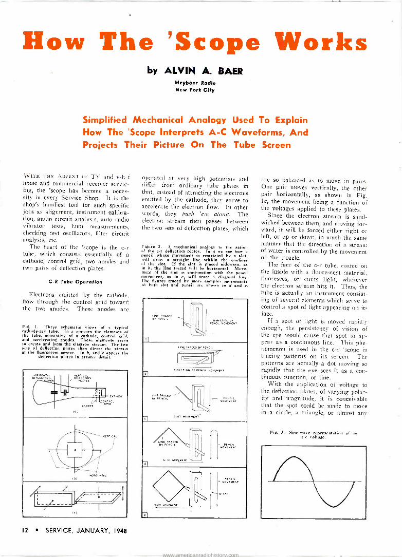
The heart of the 'scope is the c -r tube, which consists essentially of a cathode, control grid, two anodes and two pairs of deflection plates.
C -R Tube Operation
Electrons emitted by the cathode, flow through the control grid toward the two anodes. These anodes are
Fig. 1. Three schematic views of a typical cathode-ray tube. In a appears the elements of the tube, consisting of a cathode, control grid, and accelerating anodes. These elements serve to create and form the electron stream. The two sets of deflection plates then direct the stream at the fluorescent screen. In b, and e appear the
deflection plates in greater detail.
HORIZONTAL DEFLECTION
VERTICAL DEFLECTION
PLATES
ANODES
C GRI
ONT RODL
HORIZONTAL (0)
operated at very high potentials and differ from ordinary tube plates in that, instead of attracting the electrons emitted by the cathode, they serve to accelerate the electron flow. In other words, they push 'em along. The electron stream then passes between the two sets of deflection plates, which
Figure 2. A mechanical analogy to the action of the c -r deflection plates. In a we see how a pencil whose movement is restricted by a slot, will draw a straight line within the confines of the slot. If the slot is placed sideways, as in b, the line traced will be horizontal. Move- ment of the slot in conjunction with the pencil movement, as in c, will trace a diagonal line. The figures traced by more complex movements of both slot and pencil are shown in d and e.
LINE TRACED --- BY PENCIL
7
I_ DIRECTION OF PENCIL MOVEMENT
LINE TRACED BY PENCIL
DIRECTION OF PENCIL MOVEMENT
LINE TRACED ' BY PENCIL
NIS>,
IL ~- MOVEPENCMEN T
SLOT MOVEMENT 71
LINE TRACED BY PENCIL Y(
SLOT MOVEMENT
`, - PENCIL
MOVEMENT
io ,, SLOT MOVEMENT
1
`~ ¡MNT PENCIL
OVEME
START
2 1
are so balanced as to move in pairs. One pair moves vertically, the other pair horizontally, as shown in Fig. lc, the movement being a function of the voltages applied to these plates.
Since the electron stream is sand- wiched between them, and moving for- ward, it will be forced either right or left, or up or down, in much the same manner that the direction of a stream of water is controlled by the movement of the nozzle.
The face of the c -r tube. coated on the inside with a fluorescent material, fluoresces, or emits light, wherever the electron stream hits it. Thus, the tube is actually an instrument consist- ing of several elements which serve to control a spot of light appearing on its face.
If a spot of light is moved rapidly enough, the persistency of vision of the eye would cause that spot to ap- pear as a continuous line. This phe- nomenon is used in the c -r 'scope in tracing patterns on its screen. The patterns are actually a dot moving so rapidly that the eye sees it as a con- tinuous function, or line.
With the application of voltage to the deflection plates, of varying polar- ity and magnitude, it is conceivable that the spot could be made to move in a circle, a triangle, or almost any
Fig. 3. Sine -wave representation of an a -c voltage.
12 SERVICE, JANUARY, 1948
www.americanradiohistory.com

pattern. This mental concept is very important, since it will help in under- standing and interpreting what ap- pears on the screen.
Deflection Plate Voltages
The next point is best illustrated by a mechanical analogy. Let us con- sider a pencil, so placed in a slot, that its movement is restricted to an up and down movement. So long as the slot remained stationary, the pencil could only draw a straight line ; Fig. 2a. If the slot were placed on its side, as in 2b, a horizontal line would be traced.
Now, if, while the pencil were com- pleting one movement from top to bottom, the slot itself were moved in a horizontal direction, a diagonal line would result; 2c. The slope of the line would then be a function of the ratio of the two movements. That is, if both movements were equal in length, the resulting figure would be a slope of 45`.
If the pencil were to move once up and once down, while the slot com- pleted one movement from left to right, an inverted V would result ;
2d. Fig. 2e shows a perfect square drawn by the pencil. Here, the pen- cil starts at the halfway mark, and completes one movement up and down, while the slot moves from left to right and back again in the same length of time.
The tieup between this mechanical analogy and the voltages applied to the deflection plates of the c -r tube can now be traced. Fig. 2a would represent a voltage applied to the ver- tical plates, varying uniformly from zero to maximum, 2b represents the same voltage applied to the horizontal plates, and 2c would result if the volt- age were applied to both sets of plates simultaneously. The analogy can be traced similarly for Figs. 2d and 2e.
Service Men are familiar with the sine wave representation of an a -c voltage ; Fig. 3. If such a voltage were applied to the vertical plates of a c -r tube, a straight vertical line would result. If the same voltage were applied to the horizontal plates, a straight, horizontal line would re- sult. If this voltage were applied simultaneously to both sets of plates, a diagonal line would result. Ana- lyzing the reason for the wave shape, we find that in the case of the straight vertical line, the moving dot is re- tracing its path in a vertical pattern. The same reasoning applies to the horizontal line. For the diagonal line,
(Continued on page 46)
.
0 0 8 r /
. / w Ci) 6 _>
11 i ~4
En ` o a I (t)O
I 03 B o o
A
> 'i
W - I
/ > I i" It áa (.9e /
d Z I` (D.,'
8 A+
2 - - - - - I
I
I
O 3
- - - - - I
I
O a
e+ e g
.
I
I
I
e -- - -
I
I
I
I
- - - - s
7
a-
Figs. 4 (above) and 5 (below). The tracing of a Lissajou figure is here shown in detail. Two similar voltages have been applied to both the horizontal and vertical plates. However, one voltage is starting 90°, or % of a cycle later than the other. In Fig. 5, A - and + represent the vertical voltages, and B - and + the horizontal voltages. The position of the dot will then be a function of these two voltages. The resultant
picture in this case is a perfect circle.
Fig. 6. The pictures shown are used to illustrate the effect of phase relationship between two voltages on Lissajou figures. All eight pictures are the result of two identical voltages, both in frequency and amplitude, being applied to the vertical and horizontal deflection plates. However, each picture shows a different phase relationship. Starting at a, which represents zero phase shift, each successive
picture depicts a phase shift of 45°, up to and including 270°.
(a) (0)
(e) ( f )
(c) (d)
(g' (n)
SERVICE, JANUARY, 1948 13
www.americanradiohistory.com
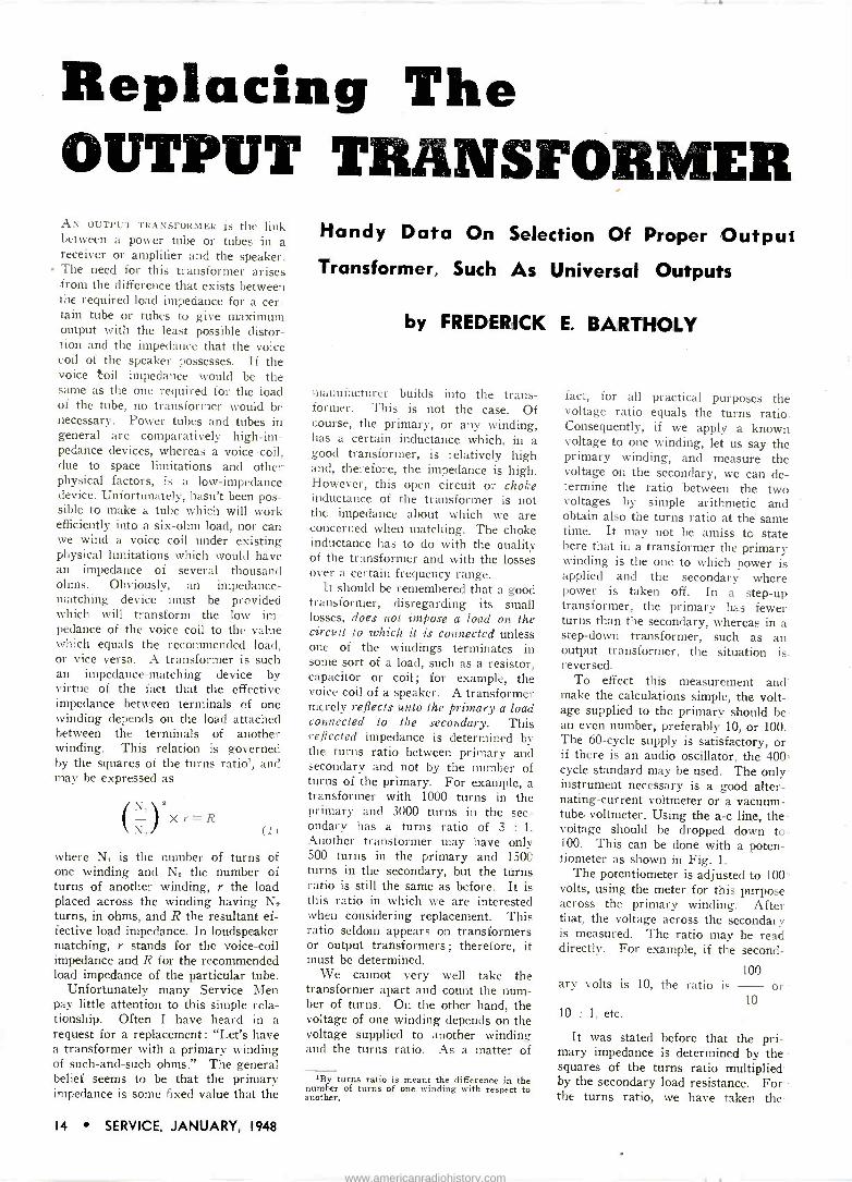
Replacing The OUTPUT TRANSFORMER AN OUTPUT TRANSFORMER is the link between a power tube or tubes in a receiver or amplifier and the speaker. The need for this transformer arises from the difference that exists between the required load impedance for a cer- tain tube or tubes to give maximum output with the least possible distor- tion and the impedance that the voice coil of the speaker possesses. If the voice toil impedance would be the same as the one required for the load of the tube, no transformer would be necessary. Power tubes and tubes in general are comparatively high -im- pedance devices, whereas a voice coil, due to space limitations and other physical factors, is a low -impedance device. Unfortunately, hasn't been pos- sible to make a tube which will work efficiently into a six -ohm load, nor can we wind a voice coil under existing physical limitations which would have an impedance of several thousand ohms. Obviously, an impedance - matching device must be provided which will transform the low im- pedance of the voice coil to the value which equals the recommended load, or vice versa. A transformer is such an impedance -matching device by virtue of the fact that the effective impedance between terminals of one winding depends on the load attached between the terminals of another winding. This relation is governed by the squares of the turns ratio', and may be expressed as
(lax r=R , (1)
where Ni is the number of turns of one winding and Nº the number of turns of another winding, r the load placed across the winding having N_ turns, in ohms, and R the resultant ef- fective load impedance. In loudspeaker matching, r stands for the voice -coil impedance and R for the recommended load impedance of the particular tube.
Unfortunately many Service Men pay little attention to this simple rela- tionship. Often I have heard in a request for a replacement: "Let's have a transformer with a primary winding of such -and -such ohms." The general belief seems to be that the primary impedance is some fixed value that the
Handy Data On Selection Of Proper Output Transformer, Such As Universal Outputs
by FREDERICK E. BARTHOLY
manufacturer builds into the trans- former. This is not the case. Of course, the primary, or any winding, has a certain inductance which, in a good transformer, is relatively high and, therefore, the impedance is high. However, this open circuit or choke inductance of the transformer is not the impedance about which we are concerned when matching. The choke inductance has to do with the ouality of the transformer and with the losses over a certain frequency range.
It should be remembered that a good transformer, disregarding its small losses, does not impose a load on the circuit to which it is connected unless one of the windings terminates in some sort of a load, such as a resistor, capacitor or coil; for example, the voice coil of a speaker. A transformer merely reflects unto the primary a load connected to the secondary. This reflected impedance is determined by the turns ratio between primary and secondary and not by the number of turns of the primary. For example, a transformer with 1000 turns in the primary and 3000 turns in the sec- ondary has a turns ratio of 3 : 1. Another transformer may have only 500 turns in the primary and 1500 turns in the secondary, but the turns ratio is still the same as before. It is this ratio in which we are interested when considering replacement. This ratio seldom appears on transformers or output transformers; therefore, it must be determined.
We cannot very well take the transformer apart and count the num- ber of turns. On the other hand, the voltage of one winding depends on the voltage supplied to another winding and the turns ratio. As a matter of
'By turns ratio is meant the difference in the number of turns of one winding with respect to another.
fact, for all practical purposes the voltage ratio equals the turns ratio. Consequently, if we apply a known voltage to one winding, let us say the primary winding, and measure the voltage on the secondary, we can de- termine the ratio between the two voltages by simple arithmetic and obtain also the turns ratio at the same time. It may not be amiss to state here that in a transformer the primary winding is the one to which power is applied and the secondary where power is taken off. In a step-up transformer, the primary has fewer turns than the secondary, whereas in a step-down transformer, such as an output transformer, the situation is. reversed.
To effect this measurement and' make the calculations simple, the volt- age supplied to the primary should be- an even number, preferably 10, or 100. The 60 -cycle supply is satisfactory, or if there is an audio oscillator, the 400 cycle standard may be used. The only instrument necessary is a good alter- nating -current voltmeter or a vacuum - tube voltmeter. Using the a -c line, the -
voltage should be dropped down to. 100. This can be done with a poten- tiometer as shown in Fig. 1.
The potentiometer is adjusted to 100' volts, using the meter for this purpose across the primary winding. After that, the voltage across the secondary is measured. The ratio may be read directly. For example, if the second -
100 ary volts is 10, the ratio is - or
10 10 : 1, etc.
It was stated before that the pri- mary impedance is determined by the squares of the turns ratio multiplied by the secondary load resistance. For -
the turns ratio, we have taken the -
14 SERVICE, JANUARY, 1948
www.americanradiohistory.com
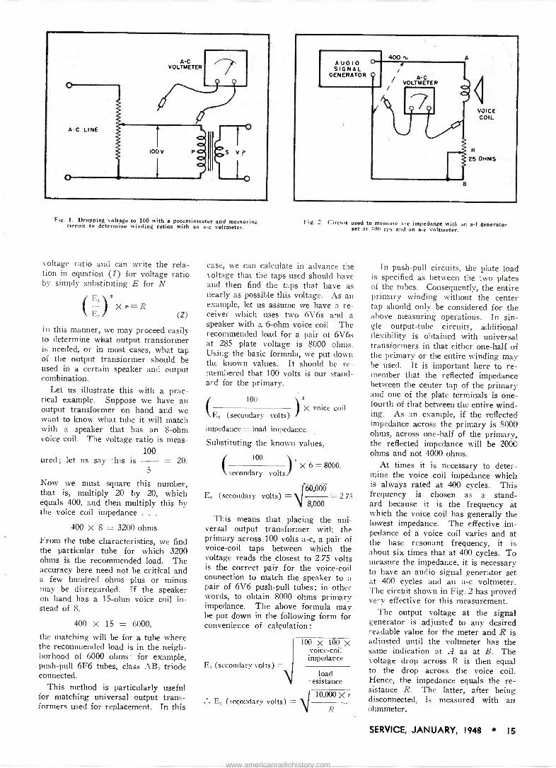
Fig. 1. Dropping voltage to 100 with a potentiometer and measuring circuit to determine winding ratios with an a -c voltmeter.
voltage ratio and can write the rela- tion in equation (1) for voltage ratio by simply substituting E for N
Ei l' \ E2/ X r
(2)
in this manner, we may proceed easily to determine what output transformer is needed, or in most cases, what tap of the output transformer should be used in a certain speaker and output combination.
Let us illustrate this with a prac- tical example. Suppose we have an output transformer on hand and we want to know what tube it will match with a speaker that has an 8 -ohm voice coil. The voltage ratio is meas -
100 ured ; let us say this is -= 20.
5
Now we must square this number, that is, multiply 20 by 20, which equals 400, and then multiply this by the voice coil impedance . . .
400 X 8 = 3200 ohms
From the tube characteristics, we find the particular tube for which 3200 ohms is the recommended load. The accuracy here need not be critical and a few hundred ohms plus or minus may be disregarded. If the speaker on hand has a 15 -ohm voice coil in- stead of 8,
400 x 15 = 6000,
the matching will be for a tube where the recommended load is in the neigh- borhood of 6000 ohms ; for example, push-pull 6F6 tubes, class AB, triode connected.
This method is particularly useful for matching universal output trans- formers used for replacement. In this
Fig. 2. Circuit used to measure v -c impedance with an a -f generator set at 400 cps and an a -c voltmeter.
case, we can calculate in advance the voltage that the taps used should have and then find the taps that have as nearly as possible this voltage. As an example, let us assume we have a re- ceiver which uses two 6V6s and a speaker with a 6 -ohm voice coil. The recommended load for a pair of 6V6s at 285 plate voltage is 8000 ohms. Using the basic formula, we put down the known values. It should be re- membered that 100 volts is our stand- ard for the primary.
100 8
X voice coil E2 (secondary volts)
impedance = load impedance.
Substituting the known values,
100
(secondary volts x 6 = 8000,
60,000 E2 (secondary volts) _ - 2.75
8,000
This means that placing the uni- versal output transformer with the primary across 100 volts a -c, a pair of voice -coil taps between which the voltage reads the closest to 2.75 volts is the correct pair for the voice -coil connection to match the speaker to a pair of 6V6 push-pull tubes; in other words, to obtain 8000 ohms primary impedance. The above formula may be put down in the following form for convenience of calculation :
E_, (secondary volts) = I
100 x 100 X voice -coil impedance
load resistance
V110000Xº EZ (secondary volts) = R
In push-pull circuits, the plate load is specified as between the two plates of the tubes. Consequently, the entire primary winding without the center tap should only be considered for the above measuring operations. In sin- gle output -tube circuits, additional flexibility is obtained with universal transformers in that either one-half of the primary or the entire winding may be used. It is important here to re- member that the reflected impedance between the center tap of the primary and one of the plate terminals is one- fourth of that between the entire wind- ing. As an example, if the reflected impedance across the primary is 8000 ohms, across one-half of the primary, the reflected impedance will be 2000 ohms and not 4000 ohms.
At times it is necessary to deter- mine the voice coil impedance which is always rated at 400 cycles. This frequency is chosen as a stand- ard because it is the frequency at which the voice coil has generally the lowest impedance. The effective im- pedance of a voice coil varies and at the base resonant frequency, it is about six times that at 400 cycles. To measure the impedance, it is necessary to have an audio signal generator set at 400 cycles and an a -c voltmeter. The circuit shown in Fig. 2 has proved very effective for this measurement.
The output voltage at the signal generator is adjusted to any desired readable value for the meter and R is adjusted until the voltmeter has the same indication at A as at B. The voltage drop across R is then equal to the drop across the voice coil. Hence, the impedance equals the re- sistance R. The latter, after being disconnected, is measured with an ohmmeter.
SERVICE, JANUARY, 1948 15
www.americanradiohistory.com
Receiver Video Amplifiers
General Functions of Video Amplifiers ... Operation of D -C Restorers in
Grid -Rectifier Systems . .. Picture -Tube Signal Circuits
THE VIDEO AMPLIFIER (one to three stages) increases the amplitude of the detected signal to a level sufficient to swing the picture -tube control grid over its full range. Two other func- tions of the video amplifier are to apply a properly polarized signal to the picture tube control grid and to es- tablish the average brightness of the picture. The former of these functions, of course, is accomplished by consider- ation of the number of video stages, and properly choosing the diode de- tector polarity to produce a negatively polarized signal on the picture tube grid. The latter function, establishing average brightness, is performed by a
d -c restorer. A typical video amplifier bas the
following features: (1) Polarity of diode is such that a
properly polarized signal appears across the diode load resistor and ap-
by EDWARD M. NOLL Instructor in Television
Temple University
pears negative on tile control grid of
picture tube. (2) Low value diode -load resistor
is used, reducing amplitude of detected signal but preserving high -frequency response up to the highest modulation component.
(3) Diode -peaking coil, which as- sists in maintaining the highs and aids in filtering out the i -f frequency.
(4) High value coupling capacitor to prevent degeneration of the lows.
(5) Contrast adjustment which con- trols amplitude of signal developed across output of video amplifier and. consequently, amplitude of signal as it
From a forthcoming book, Television For Radiomen, to be published by Macmillan.
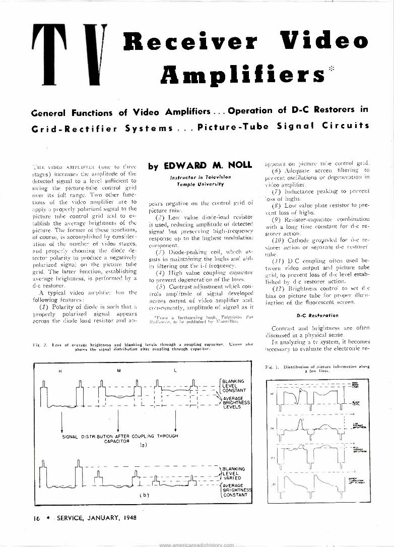
Fig. 2. Loss of average brightness and blanking levels through a coupling capacitor. Upper plot shows the signal distribution after coupling through capacitor.
H M L
it JL - - _IL BLANKING LEVEL
1 t CONSTANT r i - - 7 - - - - - T 1- AVERAGE
_ 1 I -1-t- 1 1 BRIGHTNESS -t-1 LEVELS
SIGNAL DISTRIBUTION AFTER COUPLING THROUGH CAPACI TOR
1 JL wT
fa)
BLANKING LEVEL VARIED _ - I _ L -`r_ J 1 _ - - BRIGHTNESS
(b) CONSTANT
appears on picture tube control grid. (6) Adequate screen filtering to
prevent oscillations or degeneration in
video amplifier. (7) Inductance peaking to prevent
loss of highs. (8) Low value plate resistor to pre-
vent loss of highs. (9) Resistor -capacitor combination
with a long time constant for d -c re- storer action.
(10) Cathode groµnded for d -c re- storer action or separate cl -c restorer tube.
(11) D -C coupling often used be- tween video output and picture tube grid, to prevent loss of d -c level estab- lished by d -c restorer action.
(12) Brightness control to set d -c
bias on picture tube for proper illum- ination of the fluorescent screen.
D -C Restoration
Contrast and brightness are often discussed in a physical sense.
In analyzing a tv system, it becomes necessary to evaluate the electronic re -
Fig. 1. Distribution of picture information along a few lines.
1.)
et
lel
KAM
o
- - - - s«r...r.css
_ o
°AREit w.:L .o, <t TO 174T
16 SERVICE, JANUARY, 1948
www.americanradiohistory.com

Quiet as a Moonbeam Failing on Velvet
It's Impossible to Hear a Mallory Control Operate !
Ultra -sensitive sound testing meters built for the U. S. Navy prove that the noise level of the Mallory control in operation is so Jow
as to be totally inaudible!
Contact with the talcum -fine carbon element is made by a special Mallory Alloy that passes over it smoothly and silently.
Meter used in the noise level tat. Readings were token on volume controls of all leading manu- facturers. Mallory controls gave no audible sound, registered 22% below all others in inaudible sound vibrations.
The things you look for
in a control are low noise
level, long life, accurate
resistance values and
smooth, uniform tapers. Competitive tests prove that Mallory
leads the field on all
four points!
You can use Mallory.Volume Controls, Capac-
itors and Vibrators with complete confidence.
They are carefully built to assure ease of installation and complete customer satisfac-
tion. Mallory's standardized range of sizes
and types makes the Mallory line a profitable
line to stock.
Good Service for Good Business" A Mallory plan to build business for radio - electronic service shops.
There's a unique customer follow-up system that will produce re- peat business.There's a close tie-in with the Mallory trade mark. Ask your distributor about it!
5VrleepAcil...M11.11. . . VIB1tATORS .41111
SWITCHES . . . RESISTORS . . . RECTIFIERS ... VIBRAPACK POWER SUPPLIES . . . FILTERS
°Reg. U. S. Paf. Off.
li.APPROVEgar PRECISION PRODUCTS P. R. MALLORY & CO., Inc., INDIANAPOLIS 6, INDIANA
SERVICE, JANUARY, 1948 17
www.americanradiohistory.com
BEAM CURRENT
AVERAGE BRIGHTNESS
BEAM CUTOFF
j s-__ BACKGROUND BRIGHTNESS CONSTANT BUT SHOULD VARY
(o)
BEAM CURRENT
AVERAGE BRIGHTNESS LEVELS
C
)
1
(b)
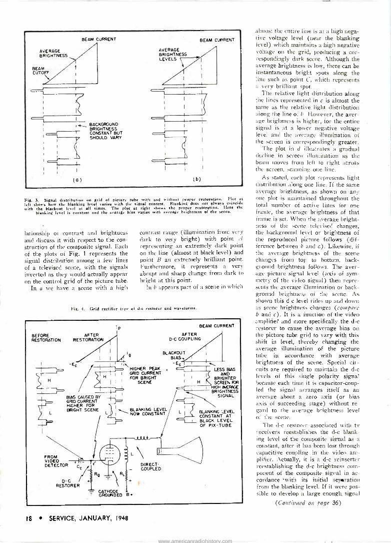
Fig. 3. Signal distribution on grid of picture tube with and without proper restoration. Plot at
left shows how the blanking level varies with the signal content. Blanking does not always coincide with the blackout level at all times. The plot at right shows the proper restoration. Here the
blanking level is constant and the avrrago bias varies with average brightness of the scene.
lationship of contrast and brightness and discuss it with respect to the con- struction of the composite signal. Each of the plots of Fig. 1 represents the signal distribution among a few lines of a televised scene, with the signals inverted as they would actually appear on the control grid of the picture tube.
In a we have a scene with a high
contrast range (illumination from very dark to very bright) with point A
representing an extremely dark point on the line (almost at black level) and point B an extremely brilliant point. Furthermore, it represents a very abrupt and sharp change from dark to bright at this point.
In b appears part of a scene in which
Fig. 4. Grid rectifier type of d -c restorer and waveforms.
BEFORE RESTORATION RESTORATION
p
AFTER
H
L
\ HIGHER PEAK I I I GRID CURRENT
FOR BRIGHT I I ' SCENE
i
BIAS CAUSED BY GRID CURRENT HIGHER FOR BRIGHT SCENE
FROM VIDEO -t I DETECTOR
D- C + RESTORER
BEAM CURRENT
AFTER D -C COUPLING
BLACKOUT BIAS -Ec .
LESS BIAS AND
BRIGHTER SCREEN RJR
HIGH IIJERAGE BRIGHTNESS
SIGNAL
BLANKING LEVEL NOW CONSTANT
DIRECT- - COUPLED
- CATHODE GROUNDED B+
L BLANKING LEVEL CONSTANT AT BLACK LEVEL OF PIX-TUBE
almost the entire line is at a high nega- tive voltage level (near the blanking level) which maintains a high negative voltage on the grid, producing a cor- respondingly dark scene. Although the average brightness is low, there can be instantaneous bright spots along the line such as point C, which represents a very brilliant spot.
The relative light distribution along the lines represented in c is almost the same as the relative light distribution along the line of b: However, the aver- age brightness is higher, for the entire signal is at a lower negative voltage level and the average illumination of the screen is correspondingly greater.
The plot in d illustrates a gradual decline in screen illumination as the beam moves from left to right across the screen, scanning one line.
As stated, each plot represents light distribution along one line. If the same average brightness, as shown onany one plot is maintained throughout the total number of active lines for one frame, the average brightness of that frame is set. When the average bright- ness of the scene televised changes, the background level or brightness of the reproduced picture follows (dif- ference between b and c). Likewise, if the average brightness of the scene changes from top to bottom, back- gf ound brightness follows. The aver- age picture signal level (axis of sym- metry of the video signal) then repre- sents the average illumination or back- ground brightness of the scene. As shown this d -c level rides up and down as scene brightness changes (compare b and c). It is a function of the video amplifier' and more specifically the d -c restorer to cause the average bias on the picture tube grid to vary with this shift in level, thereby changing the average illumination of the picture tube in accordance with average brightness of the scene. Special cir- cuits are required to maintain the d -c levels of this single polarity signal because each time it is capacitor -coup- led the signal arranges itself as an average about a zero axis (or bias axis of succeeding stage) without re- gard to the average brightness level of the scene.
The d -c restorer associated with tv receivers reestablishes the d -c blank- ing level of the composite signal as a constant, after it has been lost through capacitive coupling in the video am- plifier. Actually, it is a d -c reinserter reestablishing the d -c brightness com- ponent of the composite signal in ac- cordance 'with its initial separation from the blanking level. If it were pos- sible to develop a large enough signal
(Continued on. page 36)
IS SERVICE, JANUARY, 1948
www.americanradiohistory.com
Plastic Molded Tubular Paper Capacitors
Pioneered by Sangamo! Just as the first molded mica capacitor was designed by Sangamo in 1923, so the first plastic molded tubular paper capacitor was introduced by Sangamo in 1946. Today, after more than a year of constant improvement and develop- ment, based on reports of field service experience from coast to coast, the Sangamo Type 30 Capacitor will fully meet all new RMA Specifications.
The same advantages that Sangamo pioneered in molded micas are now available in these new paper tubulars molded in a thermo-setting plastic: capacity values are perma- nently sealed in; no wax ends to melt out at high temperatures; and their mechanical stability has been
inn OM...
improved so that it does away with the necessity for delicate handling. These advantages mean better characteristics, longer life and more dependable performance.
Sangamo Type 30 Plastic Molded Tubular Paper Capacitors can be used wherever ordinary paper capacitors are used! Heat from a soldering iron will not cause wax to run ... nothing can burn! This means greater ease of installation- fewer damaged assemblies-and
more jobs finished in less time. Radio service men and manufactur- ers will readily appreciate the many improvements embodied in the new Sangamo Type 30 Capacitor. It is definitely superior.
Write for the new Sangamo Capacitor Catalog Number 23G. It gives full information on the complete range of Sangamo Paper, Mica and Silver Capacitors.
SPRINGFIELD ILLINOIS
SERVICE, JANUARY, 1948 19
www.americanradiohistory.com

/,T -1\w , k" `\I n,lr. 1\
.1111 ay i .In)1 : Jr
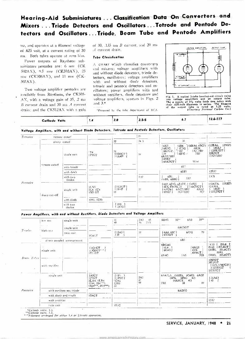
SUBMINIATURE TUBES used in hearing aids have many unusual operating characteristics. Two general types are available, output pentodes and volt- age -amplifier pentodes. The output pentodes operatç at a filament voltage of 1.25 at current drains varying from 30 to 50 ma, while the voltage - amplifier pentodes operate at a fila- ment voltage of .625 volt at current drains from 20 to 50 nia.
Maximum plate and screen voltages are 45, with most hearing aids operat- ing at lower potentials. The total B
IEXews
by L. E. STEWART
current drain for power types varies from .75 to 1.65 ma, depending on the output power, which is rated from 6
to 25 milliwatts. Voltage -amplifier tubes have voltage
gains of from 30 to 35, and are op- erated at zero bias, thereby simplify- ing circuit design. Power types use as high as 4.5 volts bias. The control
Figs. 2 (below) and 3 (right). Receiving tube classification charts.
(Courtesy RCA)
grid resistors are usually about 3
megohms, while plate -load resistors vary anywhere from 1 megohm to 30,000 ohms, depending on the tube type.
Two additional types are available in subminiature form; the double space charge tetrode, and voltage am- plifier triode. The tetrode is used as a voltage amplifier, with a voltage gain of 32.5, at a total current drain of .26 ma. Filament voltage is .625 drawing 50 ma. The triode has an amplification factor of 16, draws .15
Cathode Volts
Converters and Mixers
Converters
Mixers
pentagrid
triode-hexode
triode-heptode
octode
pentagrid
Voltage Amplifiers (with and without Diode De- tectors), Triode Detec_ tors. and Oscillators
Triodes
single unit
1.4
1A7GT 1í.A6 1135
1G4GT ,6,
with r -f pentode
medium -n ni
high -mu
with power pentode
with pentode and diode
2.0
J 106 1
1 1C7G ( (1A6 1
) 1D7G I
2.5-5
2A7
6.3
r 6A7, 6A8 ( 6BE6, 6SA71 6A8G, 6A8GT 16SA7GT (
6D8G 1
6SB7Y 7B8 707
(6K8, 6KSG)
72.6-117
12A8GT (1213E6. 12SA71 ) 12SA7GT
12K8
6J8G 7J7
(6L7, 6L7G)
7A8
1304Gí 27 56
6C4. (6C5, 6C5GT) (6P'SGT, 76) (6J5, 6J5GT) 6L5G, 7A4, 37
12J5GT
1 DBGT 3A8GT
with two diodes
twin unit
single unit
with diode 1H5 -GT 1í.H4
1B5/25S 1H6G (
55
6F7
6AD7G
) rR7, 6R7GT 1 6BF6, 6SR7, 6ST7 J 7E6 85
with two diodes
with three diodes
twin unit
ZA6
6C8ô (6F8G, 6SN7GT) 6J6 12AU7
1655, 6S5GT 1 6K5GT 7B4 1 6SF5, 6SF5GT J
I2SR7
12AH7GT 12AU7 12SN7GT
5 12F5GT ) 1 12SF5 (
I 6SQ7, 6AT6, 6AQ6 6SQ7GT 6Q7, 6(27G}
16B6G, 75J 6SZ7, 6Q7GT i
6T7G, 7B6, 7C6
(12AT6 12S7GT) (12SQ7.12SQ7GT)
6S8GT
6SC7 6SL7GT 7F7 12AX7 12SC7 12AX7 t 2SL7GT
20 SERVICE, JANUARY, 1948
www.americanradiohistory.com
Hearing -Aid Subminiatures ... Classification Data On Converters and
Mixers ...Triode Detectors and Oscillators ...Tetrode and Pentode De-
tectors and Oscillators ...Triode, Beam Tube and Pentode Amplifiers
ma, and operates at a filament voltage of .625 volt, at a current rating of 30
ma. Both tubes operate at zero bias. Power outputs of Raytheon sub-
miniature pentodes are: 6 mw (CK 502AX), 9.5 mw (CK5Q3AX), 25
mw (CK506AX), and 11 mw (CK- 507AX) .
Two voltage amplifier pentodes are available from Raytheon, the CK505-
AX, with a voltage gain of 35, .2 ma
B current drain and 30 ma A current drain: and the CK512AX with a gain
of 30, .135 ma B current, and 20 ma A current drain.
Tube Clasisfication
A CHART which classifies converters and mixers; voltage amplifiers with and without diode detectors, triode de- tectors, oscillators; voltage amplifiers with and without diode detectors, tetrode. and pentode detectors and os- cillators; power amplifiers with and without rectifiers, diode detectors and voltage amplifiers, appears in Figs. 2
and 3.*
*Prepared by the tube department of RCA.
VOLTAGE AMPL If ISMS OUTPUT TUBE,
a' al) a sNo sGU9RN
GUNNENT
GURf
Fig. 1. A typical 3 -tube hearing -aid circuit using wo voltage amplifiers and an output tube.
The a supply of 1,/2 volts feeds two tubes with heir .625 -volt filaments in series. The filament f the output tube is rated at 1.25 volts.
(Courtesy National Carbon Co.)
Cathode Volts 1.4 2.0 12.5-5 6.3 12.6-117
Voltage Amplifiers, with and without Diode Detectors, Tetrode and Pentode Detectors, Oscillators
Tetrodes remote cutoff
sharp cutoff
Pentodes
remote cutoff
sharp cut-off
single unit
with triode
with diode
with two diodes
single unit
with diode
with two diodes
35
32 24-A 36
1T4 1P5GT
34 ('iD5GP 1
11A4P f 58
161(7. 1 r6D6 1 (6BA6, 6SG7) J 6K7G. l ) íU7G l 6BJ6
I 6K7GT, ( l 5S7 ( 7A7, 7B7 L78 J 16S7G J 7117
6AB7/1853 ( 6SK7 1
1 6SK7GT ( 39/44
(12BA6, 12SG7) f 12SK7
12SK7GT f 12K7GT 12A7/12B7
6F7
6SF7 12SF7
2137 f 6B7, 1 6B8. 6B8G f 7E7
12C8
1LN5 11.4, 1U4 1N5 -GT
f 1E5GP )1B4P f
15 57
f 6J7, 6J7G, 6J7GT, 1 ( 6SJ7 i 1 6C6, 6W7G, 77 f 1 6SJ7GT f ( 6AU6 1 6AC7/1852 6AG5
1 6SH7 f 7G7/1232 7C7
(1221136, 12SH7) 12AW6 ( 12SJ7 1 12SJ7GT
(1SS. TUS)
í1F6 1
( 1F7G 1
Power Amplifiers, with and without Rectifiers, Diode Detectors and Voltage Amplifiers
Triodes
low -mu
high -mu
single unit
single unit
twin unit
direct -coupled arrangement
Beam Tubes
Pentodes
single unit
with rectifier
single unit
with medium -mu triode
with diode and triode
1 G6(:T
f 1Q5GT 1
1 3Q5GT*** ( ITS -GT
1ASGT 1CSGT 1LA4, 1LB4 (1S4, 3S4***) (3Q4***, 3V4***)
1D8GT
with rectifier
twin unit
31 49
2A3 3
46 71:1 6B4G 10** 6A3 50"
6AC5GT
( 1J6G 1
119 f 53 f 6A6, 6N71 677G 79
16N7GT f
6B5
6BG6G J 6L6 1 rr 6AQ5 l 2 6L6G f
` 6V6tíV6GT r
6Y6G 7A5 7C6
14A5 J 2516 35A5 1 25L6GT J (35B5.50A5L6GT)
(SOBS, 50L6GT)
32S7GT 70L7GT
111L7/GT7GT f
117N7GT
( 1F4 1
1 1F5G ( 1G5G 1J5G 33
2A5 47
6A4/LA (6AK6, 6G6G) 6AG7 (6F6, 6F6G 42)
7B5 (6K6G 38 41)
89143 f 25A61
f
6AD7G
12A7
tF7f:
*Cathode volts, 1.5. *Cathode volts, 7.5.
***Filament arranged for either 1.4 or 2.8 -volt operation.
SERVICE, JANUARY, 1948 21
www.americanradiohistory.com
PHONO MOTOR
O O
mom O. I
E00 P DIATOR
.E.
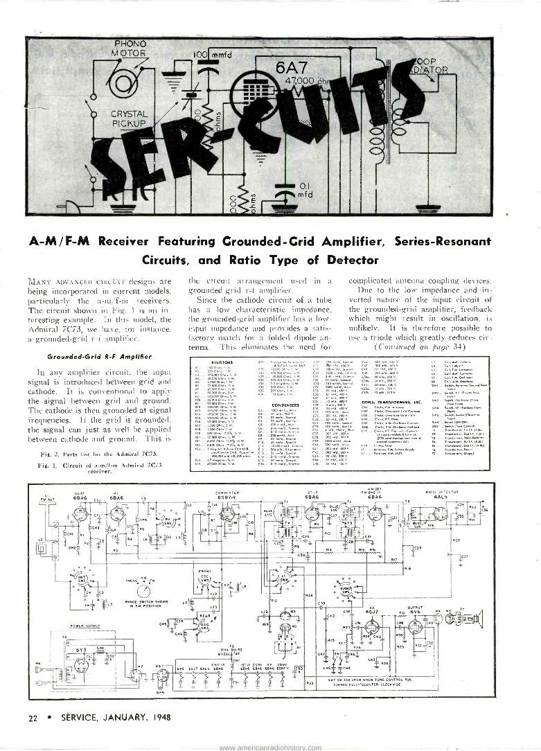
A -M/F -M Receiver Featuring Grounded -Grid Amplifier, Circuits, and Ratio Type of Detector
MANY ADVANCED CIRCL I ( designs are being incorporated in current models, particularly the a -m/f -ni receivers. The circuit shown in Fig. 1 is au in- teresting example. In this model, the Admiral 7C73, we have, for instance, a grounded -grid r -f amplifier.
Grounded -Grid R -F Amplifier
In any amplifier circuit, the input signal is introduced between grid and cathode. It is conventional to apply the signal between grid and ground. The cathode is then grounded at signal frequencies. If the grid is grounded, the signal can just as well be applied between cathode and ground. This is
Fig. 2. Parts list for the Admiral 7C73.
Fig. 1. Circuit of a -m/f -m Admiral 7C73 receiver.
the circuit arrangement used in a grounded -grid r -f amplifier.
Since the cathode circuit of a tube has a low characteristic impedance, the grounded -grid amplifier has a low - input impedance and provides a satis- factory match for a folded dipole an- tenna. This eliminates the need for
Series -Resonant
complicated antenna coupling devices. Due to the low impedance and in-'
verted nature of the input circuit of the grounded -grid amplifier, feedback which might result in oscillation, is unlikely. It is therefore possible to use a triode which greatly reduces cir-
(Continued on page 341
O
RIO
wá:
RI 4
1116
R9..
R18. 9.
R33. 033.
334
RESISTORS
39.000 Oh.., 1 w. 4.700 01..6. 1 W
I20.000 O..e. w 18000 0.... I w 3310p 03.4 l
Sp 000 0....,,awe
00:000 0..,. 5i w. }30000 Ohm..4'.W.
OF. w 6.31001.4}w. 3.300 0....) W. 100 014w. FaW.
936
äe
R R33 134
0o.61x.nhSw7
WOOST..e'.1w 1ua.000On..,:W. 0 COI. 670.000 03.4.,. W. C}]. 3 3lnega3.4. ,. W. C}3. 390 03.4,1 w. 39003.x, } W. C}5. Iap I W
cn.
CONDENSERS CaV CIO 01.
C3t
C37.. .103 .ld.. 600 V
Cle..U05 NW, 10OV
20, 500 .mld...a.
C42. OOS aM.e 600 v
. 005.M., 600 v os NM.. 300 v
C.14 .03 add . 400 v
351w.Id Special 37 meld., Special 300 N.Id.. Mke
35 ..Id., Spe:al 40 ..ld.. Sp.clel 131)0. ld., trimme.
33 meld. Spell 3.13 meld.. TWIN. fO.Nld.. Special
100 meld.. Special
goo mele special
100 As add
d- S,.U.l 5000 nwhi. Ceram.
So..+ld. Special p rr
7000 weld. RD. d.. R00 V
.0l old.. -oo v.
.10 odd., 400
O. 10 S Md . po v
ca:L Aw A601aaa Cod.fllAf. Cwt. RAC Co..wx. Ce1..N lm-. ,
.a. CaR.
G uC Pa. -e
C51a IDeN-310v (Sewed New
Now/ Swº .. Se.Rd. Rf. Dee* N60.
rl
3w3 ..ode, O.iMr 113:d No. Nee
SW6 Ode. .. s,dae,1T.R.ek... N-
d.. Gr60a.d.e G. a c. hnd. cm.-. C3Ne.e...-arceMace ses.. s-aa...a.a1...e..
low) SW6.. S.:Nh Meow') SW7.. Se:rd(i-a Cm -dl
114ea.Nreer. Ip Lf. (Fxl 31
.. NanIw.er, 2nd Lf. 11A13 ll .... 3.-.Sa.e... ero wl..v
COILS. TRANSFORAºERS, ETC.
100 weld. Spr:.l CHS... Chaim. A.M. 01lleee. C..ade
w . C.aka, fJw O.a.e Ca.3.de ... e3603e.Rf.ft.meee..e..:e.
el SfR New i #30 afd Swag e^e emend we* co* ü1
Clake.fOee Weer, f.Al. WNW Oip.
I3 .... A4/e-1a. AK 1131
3441
76 .... fe-d..m..,M1-er
FM. ANT
6
13 0
S2
rC12 LS!
RANGE SWITCH SWOON IN F.M. POSITION
' ' Ce. C52
M6 \ LT
iced
CND
o
FRONT
OSC.. 1.51031
CONVERTER 6SB7-V
T C} II
C21
6LÚ3 LUG
r- L C
1 C
g I.E.
R12
IST lf 6BA6
CO'
R9
C50T
Am PET fM2N0If
68A6 T2
RIS RIO Wee
RATIO DETECTOR
6ÁL5 rl
r- 1 jl
la wY+ ¡- 1;
? LUNr I M19
-____1 -
`1Gl3
RIT
/RIB
o
36
C39
OM) eR-
o SWSe o
ICN R
T
N20
X.-2537
T
CO, M3 1-H1 l
Nl) t1'J M2
R 6 C
TO I T ' IMI DIAL BULBS wTdVa
MAZDA LT L_ --J NT
2 ND IF. IST LW GG.RF RF CONO 6V6 65J7 GALS 613A6 6866 BRAS 6BA6 6567-Y C50
ICSI
O 3e O la
.l Cl u W
co. C60
Ca R 3
RYS R2T
A.F.
6SJ7 OUTPUT
R31 6V6
R2.T C62
} RYS
r C6$ I óS;r"`Gl
-F b/ C63 R26
C66
R301
RON 32
R21
T) ® á0
R31 593. SWIT H OPEN WHEN TONE CONTROL R26
TURNE FULLY.000NTER-CLOCRW SE
22 SERVICE, JANUARY, 1948
www.americanradiohistory.com

79etei 44ew kardede
/fade.,;,
WIN PROMOTIONS
EXTRA PAY
I TRAINED THESE MEN AT HOME
1 's
low Spring
Sixteen Years Previous Experience "Before I enrolled with NRI, I had 16 years of actual Radio ex- perience, but found many helps in your Course. I am now Ad- ministrative Assistant to the Officer in Charge of a U.. S. Army Applied Electronics School." -Wallace O. Baptist. 1907 Wil- Road, Dundalk, Md.
Tea Years Previous Experience. Doubles Earnings
"I had been servicing Radios for ten years. I found it necessary to get the technical knowledge I lacked, so I enrolled with NRI. I believe my earnings have more than doubled since taking the NRI Course."-I. L. Hanker, Jr., 278 W. 5th St., Frederick, Md.
Seven Years Previous Experience, Now Department Head
"I did not start as a beginner, but had seven years experience as a commercial Radio operator. Last April I came to work for the Oates Rubber Company to set up, train and install a complete in- dustrial equipment department." -Nordlan R. Hood, Denver. Colo.
MRI Training Helps Operator Win Advance
"Before taking the NBI Course I felt I was a phony holding a
job as Assistant Communications Operator. Now I feel worthy of the job and future advancement. I have advanced to Assistant Air- craft Communicator." Sohn Kel- ler, S. Market St., Martinsburg, Pa.
NOW LET THIS WORLD-FAMOUS
NRI COURSE HELP YOU STEP AHEAD
MAKEMORE .4fØÑEY/KR4D/Øf My Course Teaches Timesaving Service Methods, Techniques, Television, FM, Electronics
Here are just a few of the topics covered: Photoelectric Control Circuits with
Relays Peak and Band -Pass R.F. Tuning
Circuits Broadcast. All -Wave and Television
Superhet Receiver Principles Light -Sensitive Cells for Control
Circuits The Vacuum Tube as an A.C. Gen-
erator in Radio -Television Circuits Current, Voltage and Resistance
M easurements Vacuum Tube Voltmeters, Cathode
Ray Oscilloscopes Frequency Modulated Signals, the
F -M Receiver
Automatic Tuning Control Systems
Professional Radio Servicing Tech- niques
How to Isolate Defective Section and Stage
How to Isolate Defective Circuits and Part
Tuning Circuit Troubles Field and Bench Testing of Radio
Parts Uses for Optics in Electronics and
Television Practical Electronle Equipment
Essentials of Outdoor and Indoor Public Address Systems
You Build This Complete Receiver with
iiiiStandard Radio Parts I Supply. You get valuable experience testing and repairing this and many other circuits you build from N.R.I. Kits. These kits are no+ loaned to you, but become your property. Mail coupon for full details!
THE way to EARN more money in Radio is to handle MORE service
jobs in LESS time! And the N.R.I. Course is designed to help you do just that! With N.R.I. training, you KNOW the short-cuts and timesavers that speed up routine repair jobs. You KNOW how to locate trouble fast on the tough jobs as well as the easier ones. And you KNOW up-to-date servicing methods needed on FM, Television and Elec- tronics.
Find Out What N.R.I. Can Do For YOU
Read the letters at top of this page. They are frem just a few of many men who were working in Radio before they took my training. I helped them get ahead, and I can help you. Mail the coupon for my 64 -page book, "How to be a Success in Radio, Television, Electronics," FREE. See how I train you at home, how I give you UP-TO-DATE, PRACTICAL knowl- edge . . . how you get professional experience building, testing, repairing real Radio circuits with kits I send.
SAMPLE LESSON FREE
I'll send you a Sample Lesson FREE to show you how quickly you learn from my illustrated, easy -to - understand lessons. No obligation.
Get Sample Lesson and Book by mailing coupon. Just mail Coupon NOW in envelope or paste on penny postal. .1. E. Smith, President, Dept. 8A23, The National Radio Institute, Pioneer Home Study Radio School, Washington 9, D. C.
I.
Mr. J, E. SMITH, President, Dept. SAZ3
National Radio Institute Washington 9, D. C.
Mail me FREE Sample Lesson and 64 -page book. man will call. Please write plainly.)
J. E. SMITH President
National Radio Institute
VETERANS APPROVED
UNDER
G. I. BILL
'1/4;,"'Be t,a
Success in RAMO
' l 1EltYlSION li
EIECIRONICS
(No sales -
Age
Name
Address city State
(Please include l'est Office Zone Number)
1
1
1
1
1
I s
SERVICE, JANUARY, 1948 23
www.americanradiohistory.com
How 19,000 companies
up take-home pay
te/oiefierzeal Can you deduct $18.75 from $60.00 and get $66.25? Yes. And the way you can do it is mighty important to your company-and to the nation!
You start with $60, representing someone's weekly take-home pay. You deduct $18.75 for the purchase of a U.S. Savings Bond. That leaves $41.25. But $41.25 isn't what the worker takes home. He takes home $41.25 plus a $25 Savings Bond. Total (assuming he holds the Bond till maturity): $66.25.
WHAT 19,000 COMPANIES HAVE LEARNED
In the 19,000 companies that are operating the Payroll Savings Plan for the regular purchase of Savings Bonds, employees have been more contented in their jobs-ab- senteeism has decreased-even accidents have been fewer!
Those are the "company" benefits the Plan provides, in addition to extra security for individual employees.
But the Plan has other, far-reaching benefits of basic im- portance, to both your business and the national economy...
SPREADING THE NATIONAL DEBT
HELPS SECURE YOUR FUTURE
The future of your business is closely dependent upon the future economy of your country. To a major extent, that future depends upon management of the public debt. Distribution of the debt as widely as possible among the people of the nation will result in the greatest good for all.
How that works is clearly and briefly described in the free brochure shown at the right. Request your copy- today - from your State Director of the U. S. Treasury Department's Savings Bonds Division.
ACTION BY TOP MANAGEMENT NEEDED
The benefits of regular Bond -buying are as important today as ever-but war -time emotional appeals are gone. Spon- sorship of the Payroll Savings Plan by a responsible execu- tive in your company is necessary to keep its benefits advertised to your employees.
Banks don't sell Savings Bonds on the "installment plan"- which is the way most workers prefer to buy them. Such workers want and need the Payroll Savings Plan.
Those are the reasons why it's important to make sure that the Plan is adequately maintained in your company.
The State Director will gladly give you any assistance you wish.
"The National Debt and You," a 12 -pue pocket-size brochure, expresses the views o W. Randolph Burgess, Vice Chair- man o the Board of the National City Bank of New York-and of Clarence Francis, Chairman of the Board, General Foods Corporation. Be sure to get your copy
from the Treasury Department's State Director, Savings Bonds Division.
The Treasury Department acknowledges with appreciation the publication of this message by
SERVICE This is an official U.S. Treasury advertisement prepared under the auspices of ih
Treasury Department and the Advertising Council
24 SERVICE, JANUARY, 1948
www.americanradiohistory.com
Your Success In Sound How To Make Sound -System Sales That Will
Bring You More Business
ARE THE SOUND INSTALLATIONS you've made something you'd like to forget ?
Or are you happy about them, proud of them?
Pride in your work and a continued effort to give better and better service will bring, not only a sense of accom- plishment in your own mind, but also increased financial rewards.
Look at it this way: More than likely, you are either of
two classes of people-either the "hot shot" type, who can sell anything, re- gardless of its value to the purchaser, pick up a couple of fast bucks and for- get it (in which case, it may work out and it may not) ; or you are the efficient, technically aware type of man who knows what the prospective buyer really needs, and is ready to go to some trouble to make him see it. If you're the first type, you may be able to make a quick killing all right-and later find it necessary to leave town. If you're the second type, you may get off to a slow start, you may not get rich overnight; but in the long run you'll have a solid, expanding business and plenty of friends.
What I'm talking about here is not only the business of doing the simple, obvious things for which the customer asks. I'm talking about that extra service, additional effort and careful thought that are involved in satisfy- ing your customer's needs more fully, even in matters of which he himself may not be aware. You may be amazed-if you try it-to find out how that extra consideration and follow- up service pays off in terms of cus- tomer confidence and respect. And confidence and respect mean more and bigger business.
by ROBERT NEWCOMB
Newcomb Audio Products Company
The average sound installation is far from a credit either to the instal- lation engineer or to the purchaser. In far too many cases, the Service Man doesn't bother to look deeply enough into the application to find out exactly what the customer needs and exactly why. Not knowing this, he is unable to give the çustomer any valid reason for spending sufficient money.
In an ík ld,_4 yoM know something about it you t t't uy-for yourself -an in $iur i uct.l You'll pass up these ite n _; vor those that will really do u1 ih rol,. "ou won't hire a boy to n s o f and you won't buy a t\ r r plate to cook a Christen i it
Your c e n - s same. He, too, in pr , ry case, will pay a fair pric he best sound sys-
1110 tem for hi. But m.l¡ n í n w what his
needs ar 4 ss on in at this point to sh. `liu d only after- you hi' e ques 'e '. thor- oughly on h c problen . s iously as a doctor uld qu - ` onF tient. Then you ex ç in how t' - s e u ou
will of only e .' is roble s as sented t d ut-. so
ev, y lei g to about only
If your c
so
e
t. z r noun ble and pr
cle. Do no ák i for our custo n ws
a sound s s é an e probab k1 s
ous advantages. er is making a pur-
chase on behalf of some group or in- stitution, your job may not he nearly as difficult as you think. Because a group, a large corporation or institu- tion, will condemn the buyer far more for buying a poor piece of equipment than for paying more to get a good one. He may merely need to be re- minded of this point when discussing the merits of your suggestion. It can
well happen that a single failure in a
sound installation may cost the man- agement more than the cost of the entire system. There are endless variations in the requirements of ali installations. How many times have you cursed the negligence of the man- agement of some railroad station or air terminal for the fact that they cared so little about you as a customer as to install a sound system that was virtually impossible to understand.
But was it the management's fault ?
The man who sold the system would probably say it was. Yet the manage- ment would have been glad to pay more money for a sound system that could give them better performance, that would sustain or promote better public relations, if they had only been properly sold and had had full confi- dence in the sales source.
I've gone into all this to make the point that you must be armed with adequate knowledge and information in order to explain clearly to your prospect why he needs what you think he needs. To make him believe, you must first spend a sufficient amount of time investigating and discussing with him his problems, so that he will real- ize your suggestions are no snap judgment decisions, but are based on facts. His confidence in you is almost in direct proportion to the thorough- ness of your analysis of his needs.
It may seem easier at first to sell cheaper systems and not worry about the future. But each such sale puts one more obstacle in the way of your growth, reduces your pride in your work, makes it more difficult for you to improve your knowledge of the field and of men and 'women in general, which you need in any business. A little effort and straight thinking will produce bigger sales, better installa- tions, greater profits and more satis- fied customers: and the farther you go with it, the easier it will become.
SERVICE, JANUARY, 1948 25
www.americanradiohistory.com
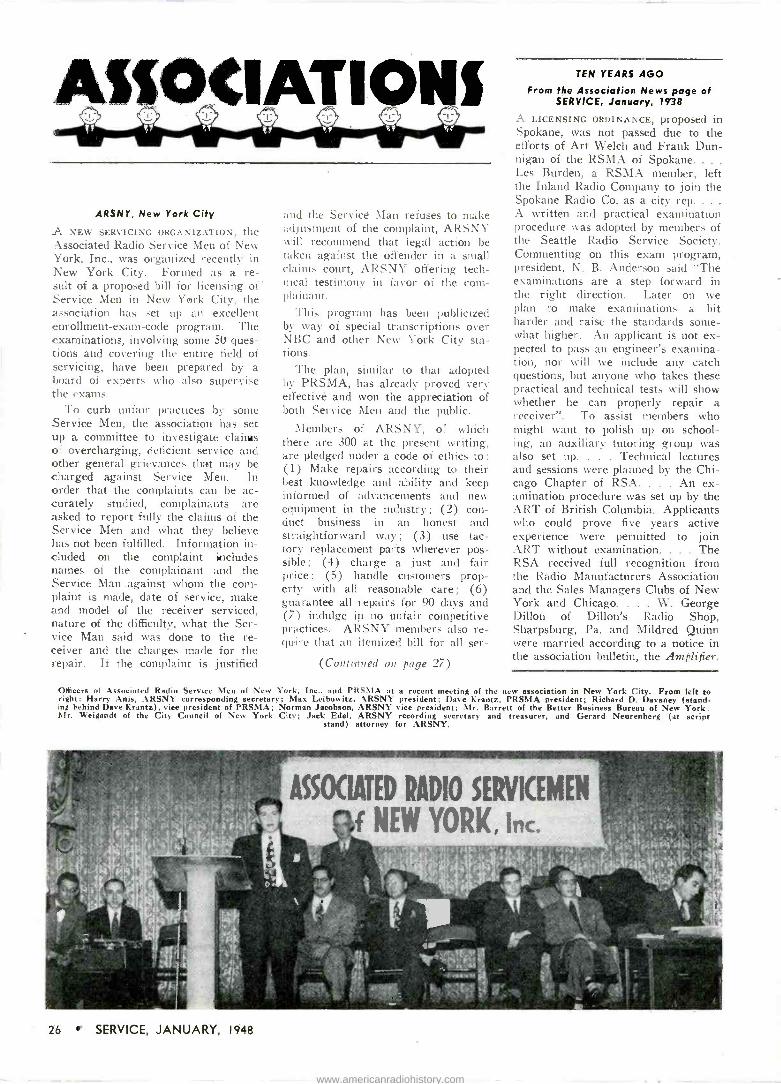
L a
AUOCIATI O
ARSNY, New York City
A NEW SERVICIN, oRGÄ\I/AEION, the Associated Radio Service Men of New York, Inc., was organized recently in New York City. Formed as a re- sult of a proposed bill for licensing of Service Men in New York City, the association has set up an excellent enrollment -exam -code program. The examinations, involving some 50 ques- tions and covering the entire field of servicing, have been prepared by a board of experts who also supervise the exams.
To curb unfair practices by some Service Men, the association has set up a committee to investigate claims of overcharging, deficient service and other general grievances that may be charged against Service Men. In order that the complaints can be ac- curately studied, complainants are asked to report fully the claims of the Service Men and what they believe has not been fulfilled. Information in- cluded on the complaint -includes names of the complainant and the Service Man .against whom the com- plaint is made, date of service, make and model of the receiver serviced, nature of the difficulty, what the Ser- vice Man said was done to the re- ceiver and the charges made for the repair. If the complaint is justified
and the Service Man refuses to make adjustment of the complaint, ARSNY will recommend that legal action be taken against the offender in a small claims court, ARSNY offering tech - ideal testimony in favor of the com- plainant.
This program has been publicized by way of special transcriptions over NBC and other New York City sta- tions.
The plan, similar to that adopted by PRSMA, has already proved very effective and won the appreciation of both Service Men and the public.
Members of ARSNY, of which there are 300 at the present writing, are pledged under a code of ethics to: (1) Make repairs according to their best knowledge and ability and keep informed of advancements and new equipment in the industry; (2) con- duct business in an honest and straightforward way; (3) use fac- tory replacement parts wherever pos- sible; (4) charge a just and fair price; (5) handle customers prop- erty with all reasonable care; (6) guarantee all repairs for 90 days and (7) indulge in no unfair competitive practices. ARSNY members also re- quire that an itemized bill for all ser -
(Continued on page 27)
TEN YEARS AGO
From the Association News page of SERVICE, January, 1938
A LICENSING ORDINANCE, proposed in Spokane, was not passed due to the efforts of Art Welch and Frank Dun- nigan of the RSMA of Spokane... .
Les Burden, a RSMA member, left the Inland Radio Company to join the Spokane Radio Co. as a city rep... .
A written and practical examination procedure was adopted by members of the Seattle Radio Service Society. Commenting on this exam program, president, N. B. Anderson said "The examinations are a step forward in the right direction. Later on we plan to make examinations a bit harder and raise the standards some- what higher. An applicant is not ex- pected to pass an engineer's examina- tion, nor will we include any catch questions, but anyone who takes these practical and technical tests will show whether he can properly repair a receiver". To assist members who might want to polish up on school- ing, an auxiliary tutoring group was also set up. . . . Technical lectures and sessions were planned by the Chi- cago Chapter of RSA. . . . An ex- amination procedure was set up by the ART of British Columbia. Applicants who could prove five years active experience were permitted to join ART without examination. . . . The RSA received full recognition from the Radio Manufacturers Association and the Sales Managers Clubs of New York and Chicago. . . . W. George Dillon of Dillon's Radio Shop, Sharpsburg, Pa. and Mildred Quinn were married according to a notice in the association bulletin, the Amplifier.
Officers of Associated Radio Service Men of New York, Inc., and PRSMA at a recent meeting of the new association in New York City. From left to right: Harry Anis, ARSNY corresponding secretary; Max Leibowitz, &RSNY president; Dave Krantz, PRSMA president; Richard D. Devaney (stand- ing behind Dave Krantz), vice president of PRSMA; Norman Jacobson, ARSNY vice president; Mr. Barrett of the Better Business Bureau of New York; Mr. Weigandt of the City Council of New York City; Jack Edel, ARSNY recording secretary and treasurer, and Gerard Neurenberg (at script
stand) attorney for ARSNY.
26 r SERVICE, JANUARY, 1948
www.americanradiohistory.com
Continued from page 26)
vices and parts used be given to all customers. All members of the ARSNY will receive an emblem for shop display, which will state that the member has been examined by a
board of examiners and certified as competent in repair of home receivers and auto radios.
Max Leibowitz is president of the association. Harry Anis is corre- sponding secretary, Norman Jacobson, vice president, and Jack Edel is re- cording secretary and treasurer.
PRSMA, Philadelphia, Pa.
MEMBERS OF K Y \\', Robert E. White, general manager and Arthur C. Scho- field, station advertising manager, received honorary memberships in the Philadelphia Radio Service Men's association recently.
In bestowing the memberships, Dave Krantz, PRSMA president thanked the KYW executives in be- half of the members for the station's fine cooperation in serving as a liai- son in special programs and through special announcements during 1947. KYW publicized the work of PRSMA and urged listeners to look for the PRSMA decal when hiring a Service Ilan for receiver repair.
PRSMA, which has been active in Philadelphia for the past 15 years, has set up a broadcast and publicity com- mittee to work with KYW. KYW provides a separate 'phone service for Service Men through which custo- mers can place orders for repair work. When a customer calls, KYW secretary. Miss Joey Thomas checks a map of greater Philadelphia, which is clotted with locations of PRSMA
` shops and refers the customer to the nearest Service Shop.
Officers of PRSMA include Dave Krantz. president: Richard D. De- vaney, vice president: Stanley W. Myers. treasurer and F. B. Guthrie, recording secretary.
RSA, Trenton, N. J.
A NOTE FROM Secretary J. T. Dzic- bek reveals that the new name of the Delaware Valley Service Men's Asso- ciation is Radio Service Men's Asso- ciation of Trenton, N. J.
A reorganization of the association is now being held and new officers
- will be announced very soon.
Complete, Easy Instructions for Repairing Common Troubles in Practically Every Model and Make of Radio in Use Today
Eliminates Needless Testing - Enables You to Repair Two Radios in the Time
Ordinarily Required for One
PAYS FOR ITSELF ON THE FIRST JOB ! What's wrong with the radio you want to repair? A defec-
tive transformer? Wiring insulation trouble? A faulty capacitor or resistor? Don't guess! Don't waste time in needless, tedious testing ! Just look up that particular make and model in Ghirardi's famous RADIO TROUBLESHOOT- ER'S HANDBOOK. Nine times out of ten, this big book will tell you exactly what is wrong-and exactly how to repair it. You don't have to be an expert to use the HANDBOOK- and there's no better way of getting in- valuable, practical service training. Over 400 pages are chock-full of this factual Case History repair data on over 4,800 receivers, auto radios and record changers of 202
different manufacturers-practically every radio set in use today ! Over 300 additional pages contain hundreds of re- pair charts, tube charts, data on tuning alignment, trans- former troubles, tube and parts . substitution data, color codes-all designed to help you repair any radio ever made EASIER, BETTER and FASTER. Id,al for either busy service shops or for beginners. Only $6 complete - on our 5 -Day Money -back Guarantee basis.
Ghirardt's RADIO TROUBLESHOOTER'S HAND- BOOK í above) is the ideal book to have on hand for training new helpers, repairing either cheap or expensive sets quickly and profitably, eliminating needless test tine and equipment-and MAKING MORE, MONEY.
MAKES 90 OUT OF 100 RADIO
TROUBLES Easy to Repair!
TELLS WHAT TO DO EXACTLY
HOW TO DO IT As valuable to a radio repair man as a recipe
book is to a cook!
ALL THE SCIENCE OF RADIO -
ELECTRONIC SERVICING GIAN TBOOK
MAKES COMPLICATED JOBS EASY TO Alfred A. Ghrardi'a MODERN RADIO SERVICING
gives you a COMPLETE, MODERN EDUCATION in truly profes,ional radio -electronic service methods of the kind that will be your "Open, sesame!" to the big -money oP-
portunities that only well -trained servicemen are in a posi-
tion to grasp. It is a complete, scientific servicing course from A to Z. You'll be surprised how easily understandable it makes every phase of the work even if you have had no
previous service training. And, if you are already in the business, you'll be pleased to learn how this big 1300 -page book will serve as a "refresher" course. Not only will it help you handle repair jobs quicker, better and more profitably, but it also will give you the necessary basic training to equip you for profitable industrial electronic work. Specifically written and designed for home study. 1300 pages: 706 clear illustrations. 720 Self -Test Review
Questions make it easy for you to check your progress every sip of the way. Fully indexed. Only $5 on our famouo -Day- Money -back Guarantee.
MONEY -BACK GUARANTEE MURRAY HILL BOOKS, Inc., Dept. S-18
232 Madison Ave., New York 16, N. Y.
n Iulosed rind $ for books checked: or n send C.O.D. (U.S.A. only) for this amount plus Postage. I may
return the books for refund within 5. days if not fully
satisfied. Ç) RADIO TROUBLESHOOTER'S HANDBOOK $5
(*3.10 foreign, n MODERN RADIO SERVICING $5 ($5.50 foreign)
Cl MONEY -SAVING COMBINATION OFFER: Both of the above big books, only $9.50 ($10.50 foreign)
Name
Address
City & Dist. No. State
1
DO!
ENDORSED BY EXPERTS EVERYWHERE
From beginning to end, MODERN RADIO SERVICING brings you the kind of modern professional "Know How" that will pay big dividends for years to come. Gives complete data on test instruments and their use, pre- liminary trouble checks, scientific cir- cuit analysis and trouble -shooting, parts repair and substitution, how to start and operate a successful service business and many Miter subjects.
SPECIAL OFFER II
Let RADIO TROUBLE - SHOOTER'S HANDBOOK save you time on common radio service jobs! Let MODERN RADIO SERVIC- ING train you for complete professional, electronic work. Get BOTH BIG BOOKS at the special price of only $9.50 for the two. Send cou-
pon today!
SERVICE, JANUARY, 1948 27
www.americanradiohistory.com

Sca'icinqRcIps Mixer Inputs With Twin Triodes, Pentodes And Cascaded Circuits For Up to Eight Inputs ...
MIXER SYSTEMS are essentially circuits which provide multiple input sources tor an audio amplifier. In general, each device feeding the amplifier re- quires an individual input circuit both for its control and to isolate it from other input sources.
Fig. 1 shows an input system in its simplest form. Here, two high im- pedance inputs have been connected so that either one may be used to drive the audio amplifier, whose first stage is shown.
The circuit shown in Fig. 1 is used for illustration, rather than as an ex- ample of design, since, in a high gain
by CHARLES P. ELLIOTT
amplifier, a very loud thump would result every time the switch were made from one input to the other. The proper design of an multiple input system would therefore require some method for a smooth transition from one channel to another.
A simple method of accomplishing this is shown in Fig. 2. Here, a twin triode has been used. Resistors have been inserted in series with the plate circuits to isolate the two systems, and also increase the individual plate load -
Fig. 6. A mixer input for eight inputs cascaded to feed a common amplifier with twin triodes.
mg so as to reduce the distortion fac- tor for output voltage.
Fig. 3 shows a similar system em- ploying pentodes instead of triodes. Because pentode -plate circuits are usu- ally very high impedance, the use of isolating resistors is unnecessary. In addition, the stage gain for the pentode is very much higher than for the tri- ode.
The proper design of a multiple -in- put system is governed by two impor- tant constants of the input devices ;
the impedance and voltage output. For example, a magnetic pickup may be either a high or low -voltage device, and is usually a low -impedance device. Crystal pickups are invariably high impedance, high -voltage sources. Most microphones are low voltage devices, with the exception of the carbon mike. Thus, it may he seen that the design of an appropriate input stage must be determined by these factors.
High impedance devices may be fed directly into the grid of a tube. Low - impedance devices require the use of an input transformer; Fig. 4. Trans- formers in addition to converting low - impedance sources to high impedance, may also amplify the input voltage, depending on the turns ratio.
Fig. 5 shows a method of connecting two phono inputs to one tube. The use of the isolating resistors prevents in- teraction between controls. Thus, one pickup can be set at zero input with- out materially decreasing the voltage input of the second pickup.
A large number of input systems requires the cascading of the various circuits, before feeding the entire group into an amplifier. A mixer input system exemplifying such a circuit is shown in Fig. 6. Here, eight input cir- cuits have been cascaded to feed a common amplifier using twin triodes. Since each stage will contribute its own gain, it is necessary that low -gain triodes he used. Additional reduction of the stage gain may be controlled by increasing the size of the isolating re- sistors in the plate circuit, and by not bypassing the cathode resistors. The use of feedback will have the salutary
(Continued on page 33)
28 SERVICE, JANUARY, 1948
www.americanradiohistory.com
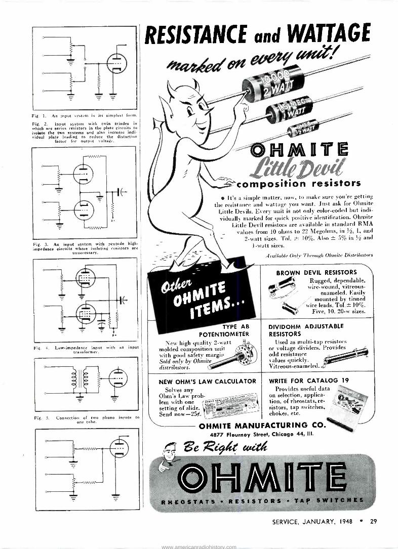
Fig. 1. An input system in its simplest form.
Fig. 2. Input system with twin triodes in which are series resistors in the plate circuits to isolate the two systems and also increase indi- vidual plate loading to reduce the distortion
factor for output voltage.
Fig. 3. An input system with pentode high - impedance circuits where isolating resistors are
unnecessary.
Fig. 4. Law -impedance input with an input transformer.
Fig. S. Connection of two phono inputs to one tube.
RESISTANCE and WATTAGE
eivziedtet 'it/
HMllTIE P
composition resistors It's a simple matter, now, to make sure you're getting
the resistance and wattage you want. Just ask for Ohmite Little Devils. Every unit is not only color -coded but indi- vidually marked for quick positive identification. Ohmite
Little Devil resistors are available in standard RMA _ values from 10 ohms to 22 Megohms, in M, 1, and
2 -watt sizes. Tol. 10%. Also ± 5% in % and 1 -watt sizes.
TYPE AB POTENTIOMETER
New high quality 2 -watt molded composition unit with good safety margin Sold only by Ohmite distributors.
Available Only Through Ohmite Distributors
BROWN DEVIL RESISTORS
Rugged, dependable, /k: wire -wound, vitreous-
enameled.j Easily ter` mounted by tinned wire leads. Tol.- 10%.
Five, 10. 20-w sizes.
DIVIDOHM ADJUSTABLE RESISTORS
Used as multi -tap resistors or voltage dividers. Provides odd resistance values quickly. Vitreous-enameled. .2'
NEW OHM'S LAW CALCULATOR Solves any
Ohm's Law prob- lem with one setting of slide. Send now -250.
WRITE FOR CATALOG 19
Provides useful data on selection, applica- tion, of rheostats, re- sistors, tap switches, chokes, etc.
OHMITE MANUFACTURING CO. 4877 Flournoy Street, Chicago 44, III.
RHEOSTATS * RESISTORS * TA! SWITCHES
SERVICE, JANUARY, 1948 29
www.americanradiohistory.com
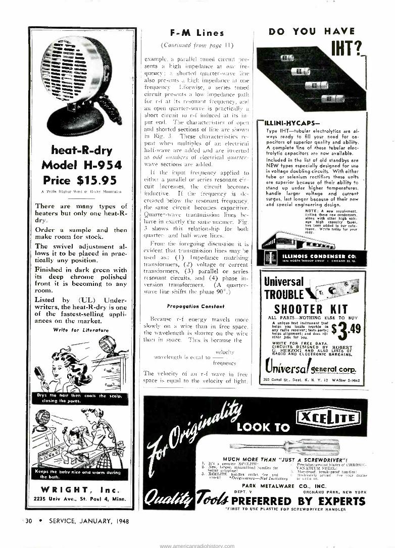
)4
Model Price
A Trifle
There heaters dry. Order make The lows tically Finished its deep front room. Listed writers, of the ances
....._
. .. .. a - r SSW no
aloe t art O
etotow
¡¡ , r......: emir
heat -R -dry H-954
$15.95 Higher West of Rooky Mountains
of -
are many types but only one heat -R
a sample and then room for stock.
swivel adjustment al- it to be placed in prac-
any position. in dark green with
chrome polished it is becoming to any
by (UL) Under- the heat -R -dry is one fastest -selling appli-
on the market. Write for Literature
h t--, Drys the
closing
,s,
aS
hair then cools the scalp, the pores.
4iet-4k21
I
Ste \:1',)1,-4/CA
Keeps the baby nice and warm during the bath.
WRIGHT, Inc. 2235 Univ Ave., St. Paul 4. Minn.
F -M Lines (Continued front page 11)
example, a parallel tuned circuit pre- sents a high impedance at one fre- quency ; a shorted quarter -wave line also presents a high impedance at one frequency. Likewise, a series tuned circuit presents a low impedance path for r -f at its resonant frequency, and am open quarter -wave is practically a short circuit to r -f induced at its in- put end. The characteristics of open and shorted sections of line are shown in Rig. 3. These characteristics re- peat when multiples of an electrical half -wave are added and are inverted as odd numbers of electrical quarter - wave sections are added.
If the input frequency applied to either a parallel or series resonant cir- cuit increases, the circuit becomes inductive. If the frequency is de- creased below the resonant frequency. the same circuit becomes capacitive. Quarter -wave transmission lines be- have in exactly the same manner. Fig. 3 shows this relationship for both quarter- and half -wave lines.
From the foregoing discussion it is evident that transmission lines may be used as: (1) Impedance matching transformers, (2) voltage or current transformers, (3) parallel or series resonant circuits, and (4) phase in- version transformers. (A quarter - wave line shifts the phase 90°.)
Propagation Constant
Because r -f energy travels more slowly on a wire than in free space, the wavelength is shorter on the wire than in space. This is because the
wavelength is equal to velocity
frequency
The velocity of an r -f wave in free space is equal to the velocity of light,
DO YOU HAVE
IHT?
ILLINI-HYCAPS- Type IHT-tubular electrolytics are al- ways ready to fill your need for ca- pacitors of superior quality and ability. A complete line of these tubular elec- trolytic capacitors are now available. Included in the list of old standbys are NEW types especially designed for use in voltage doubling circuits. With either tube or selenium rectifiers these units are superior because of their ability to stand up under higher temperatures, handle larger voltage and current surges, last longer because of their new and special engineering design.
NOTE: A new supplement, listing these new condensers, along with other high volt- age high capacity types, has been added to our cata- logue. Write today for your copy.
ILLINOIS CONDENSER CO. 1616 NORTH THROW. STREET CHICAGO 22.'L..
Universal TROUBLE N'---'
SHOOTER KIT ALL PARTS-NOTHING ELSE TO BUY
A unique test instrument that helps you locate trouble in any radio receiver; tests parts; helps alignment; and does 101 other jobs for you.
WRITE FOR FREE DATA, CIRCUITS DESIGNED BY ROBERT G HERZOG AND ALSO LISTS OF RADIO AND ELECTRONIC BARGAINS
$ ß.4R
niversa (Sefle!aI co p. 365 Canal St., Dcot, K. N. Y. 13 WAlker ;i-91142
¡¡sae LOOK TO - MUCH MORE THAN "JUST
I. It's a genuine XCELITE! 2. New, larger, streamlined handles for
better gripping! 3. XCELITE handles resist fire and
shock! 0Oririnatoro-Not Imitators
PARK METALWARE
Zieb DEPT. V
PREFERRED
A SCREWDRIVER"! Precision -ground blades of CHROME - VANADIUM STEEL! Mar -proof, break -proof handles! Moderately wired! See your dealer or write us.
CO., INC. ORCHARD PARK, NEW YORK
BY EXPERTS 'FIRST TO USE PLASTIC FOR SCREWDRIVER HANDLES
30 SERVICE, JANUARY, 1948
www.americanradiohistory.com

01 300,000;000 meters per second. Therefore,
a wavelength in meters - 300,000,000
when f is in cycles per second. The electrical length, previously mentioned, then differs slightly from the length in terms of the free space wavelength. The capacitance effects between the wires themselves and between each wire and ground decrease the velocity of propagation on the line. The in- sulating material between the wires have a dielectric constant greater than air, which increases the effective capacitance, which also affects the wave velocity. The factor by which the velocity in a line is reduced from the velocity in free space is called the propagation constant. It is always less than one.
The propagation constant for some common lines are: Parallel line (open, bare) 0.975 Parallel tubing 0.95 Parallel line (polethylene insu-
lated, 300 ohm f -m leadin) 0.85 Coaxial line (air insulated) 0.85 Coaxial line (rubber insulated) 0.60 Twisted pair 0.60
Most manufacturers give the propa- gation constant on every spool or roll of line intended for r -f transmis- sion. To find the wavelength of a certain frequency on a specific line, multiply the wavelength in free space by the propagation constant.
Analysis of Different Types of Lines
The following types of lines are recommended for use as antenna leadins:
(1) Parallel polethylene insulated line.
(2) Coaxial plastic insulated line. (3) Shielded pair, rubber covered
line. (4) Twisted pair.
The parallel polethylene insulated line has become the most popular type transmission lines for f -m antenna leadin in the average home. It is economical, easy to install, has low losses (about 1.5 db per hundred feet) and is available in a variety of impedances (Z0), including 300 ohms, which is the RMA suggested standard input impedance for f -m receivers. For relatively short leadins (75 to 100 feet) this line is very satisfactory.
Coaxial Lines
The chief purpose of coaxial lines is to keep down radiation losses. In
(Continued on page 32)
AS7AiIC Introduces
NEW"LT"CARTRIDGE IN
STAMPED HOUSING MODELS
Model "LT1-M" Die Cost Housing Weight 28 Grams
Model `LT2-M" Stamped Steel
Weight 20 Grams
Model "LT3-M" Stamped
Aluminum Weight 11 Grams
geeelade of the LOW Needle Talk, LOW Needle Pressure and LOW Price, the "LT" Series Crystal Cartridges are highly recommended for use with all types of record changers and manually operated phonographs. The "LT" employs a Type "T," matched, replaceable Needle with an electro -formed precious metal tip.
Special Literature is available.
For those who prefer a de luxe Reproducer.
Asiatic suggests earnest consideration of the "QT" (Quiet Talk) CRYSTAL CAR- TRIDGE-with matched, re- placeable "Q" Needle, sap- phire or precious metal tipped.
In providing this
selection, Astatic
makes it possible
to choose the cartridge models having the proper weight to provide optimum needle pressure and
pickup inertia char-
acteristics with va-
rious types of arms.
Zee THESE "LT" FEATURES
I. Low Needle Talk
2. Low Needle Pressure
3. Low Price
4. Replaceable "T" Needle
5. Cutoff Frequency, 4,000 c.p.s.
6. Output Voltage, 1.00
volt (Avg. at 1,000
c. p. s.) .
7. Choke of three weights: Die Cast, 28
Grams; Stamped Steel, 20 Grams; Stamped
Aluminum, II Grams
8. Needle Guard Posts
9. Standard Dimensions
Copyright, Asiatic Corp., 1947 id SERVICE, JANUARY, 1948 31
www.americanradiohistory.com
I. I
9tía GREENOHMI * That means the toughest thing
in wire -wound power resistors. A Greenohm "can take it"-day after day, year after year. Handles heavy overloads without flinching. The exclusive cold -setting inorganic cement coating means that the wire winding is unimpaired in fabrica- tion. A Greenohm withstands high operating temperatures, cooling, frequent on -off operation, without cracking, flaking, peeling. Definite- ly, no tougher power resistors are made.
Fixed and adjustable types. In standard, carried -in -stock resistance values, from 5 to 200 watt ratings. Your Clarostat jobber stocks them for your convenience.
NEW Catalog...
CIAROSIAI
Lists big line of resistors, controls and resistance devices. Copy on request.
eyref4Z.,-A, CIAROSTAT MFG. CO., Inc. 285.1 N.61ó St., Brooklyn, N.Y.
In Canada .
CANADIAN MARCONI CO., LTD. Montreal, P.O., and Branches
two -wire parallel lines, the electric and magnetic fields extend out into space thus causing radiation losses and noise pickup from other sources. In a coaxial line, however, no fields ex- tend outside of the outer conductor. All fields exist in the space between the two conductors. The coaxial line i:,; therefore, perfectly shielded. (This is not actually true in the flexible coaxial line for there is some leakage through the flexible metal braid of the outer conductor. Losses also occur in the rubber or plastic insulation used between the inner and outer conductor.
Shielded pair lines usually consist of two parallel conductors separated from each other and surrounded by an in- sulating material, usually plastic, and contained in a copper braid tubing which acts as a shield for the conduc- tors. This copper braid is usually covered with a protective coating of rubber to protect it from moisture and mechanical damage.
The most important advantage of the shielded pair is the fact that the two conductors are balanced to glolwld; that is, the capacity between each conductor and ground is uniform along the entire length of the line. To appreciate this improvement, let us consider the open pair or unshielded line. If radiation in such a line is to be prevented, the current flow in each conductor must be equal in amplitude to set up equal and opposite magnetic fields and thereby cancel out. This condition can be obtained if the line is well in the clear of all obstructions ;
but suppose that the line runs near some ground or conducting surface. and that one of the two conductors is nearer that obstruction than the other. A certain amount of capacity will exist between the two conductors and the conducting surface over a length of the line, depending upon the size of the obstruction. This capacity acts as a parallel conducting path for each half (conductor) of the line, causing a division of current flow between each conductor arid the interfering, or stray capacity. Since one conductor is nearer the obstruction than the other, the current will be greater on one line than on the other ; therefore, incom- plete cancellaton will result and radia- tion will take place.
Since the spacing between the two conductors of a shielded pair is con- siderably less than that of an un- shielded pair; the characteristic im- pedance of the line is lower. Also the propagation constant of a shielded pair is usually lower than that for an open line.
The twisted pair, as the name im- plies, consists of two insulated wires
S.S.S. "Servicing by Signal Substitution"
Learn about this modern dynamic approach to radio servicing with ONLY BASIC TEST
EQUIPMENT. ... Fully described in a 120 poge book available from your Precision Distributor or factory at MM. ... Schools are invited to inquire regarding quantity orders from our Educational Division.
PRECISION APPARATUS COMPANY INC.
ELMHURST 1, N. Y. Manufacturers el Fine Test Equipment
RADIO TELEVISION ELECTRICAL LABORATORY
GREYLOCK A DEPENDABLE NAME IN
RADIO TUBES GT, Glass and Miniature Types
All Tubes Individually Boxed 12SA7, I2SK7, 12807, SOLE, 12AT6. 12BA6,
1213E6, 35W4, 5085 euh 394 IRS. 155. 1T4. 384. 304, OAKS. SACS 6AC7.
liAQ5, 613E6, 68A6, 6AUB, 6B1B. 6X4 eaeh 490 32L7. 70L7. 117L7 each 594
All Tubes Carry RMA 90 -Day Guarantee
PM SPEAKERS 4" Alnico No. 5 each 41.19 5" Alnico No. 5 each 1.29
TERMS: Net C.O.D. No order accepted for has than $5.00.
WRITE FOR BARGAIN CATALOG S-1
Greylock Electronic Supply Co. 30 Church Street New York 7. N. Y.
tae THE COMBINATION
DRILL GRINDER
The "Craft Pal" is a combina- tion Drill and grinder, complete u'ith MOTOR -CHUCK -GRIND- ING WHEEL -SET .OF 5
GRINDING STONES -STEEL. WASHERS - LOCK PIN.
Home Craftsmen, Hobbyists, Small Shop Owners will find "Craft Pal" indispensable for doing light duty grinding and drilling. Motor is cool -running, 1/20 H.P., 60 C. 110 volts A.C., 3500 R.P.M., with finger control switch.
SEND NO MONEY - FILL IN AND MAIL TODAY MINOR MACHIN CORP 45 N. Division St., Buffalo, N. Y., Dept. 5 , Send parcel post C.O.D. one "CRAFT PAL." ' complete with full equipment for $8.95
Name
Address
L Charges Paid lt Money Accompanies Orderis BB iii! LIB 11118 11118 IIIR MI MI riffle 11118 ZIO
MINOR MACHINE CORP., 45 N. Division St. BUFFALO, N. Y.
1
32 SERVICE, JANUARY, 1948
www.americanradiohistory.com
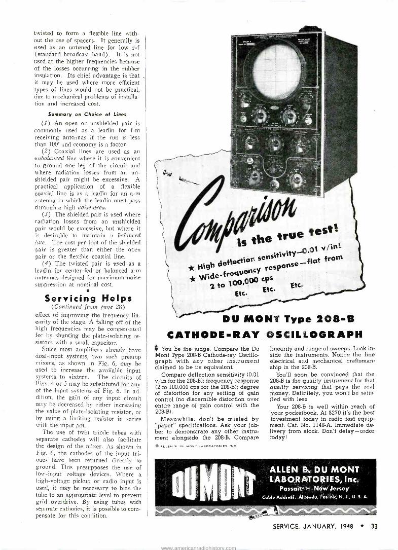
twisted to form a flexible line with- out the use of spacers. It generally is used as an untuned line for low r -f (standard broadcast band). It is not used at the higher frequencies because of the losses occurring in the rubber insulation. Its chief advantage is that it may be used where more efficient types of lines would not be practical, due to mechanical problems of installa- tion and increased cost.
Summary on Choice of Lines
(1) An open or unshielded pair is commonly used as a leadin for f -m receiving antennas if the run is less than 100' and economy is a factor.
(2) Coaxial lines are used as an unbalanced line where it is convenient to ground one leg of the circuit and where radiation losses from an un- shielded pair might be excessive. A practical application of a flexible coaxial line is as a leadin for an a -m antenna in which the leadin must pass through a high noise area.
(3) The shielded pair is used where radiation losses from an unshielded pair would be excessive, but where it is desirable to maintain a balanced line. The cost per foot of the shielded pair is greater than either the open pair or the flexible coaxial line.
(4) The twisted pair is used as a leadin for center -fed or balanced a -m antennas designed for maximum noise suppression at nominal cost.
Servicing Helps (Continued from page 28)
effect of improving the frequency lin- earity of the stage. A falling off of the high frequencies may be compensated for by shunting the plate -isolating re- sistors with a small capacitor.
Since most amplifiers already have dual -input systems, two such preamp mixers, as shown in Fig. 6, may be used to increase the available input systems to sixteen. The circuits of Figs. 4 or 5 may be substituted for any of the input systems of Fig. 6. In ad- dition, the gain of any input circuit may be decreased by either increasing the value of plate -isolating resistor, or by using a limiting resistor in series with the input pot.
The use of twin triode tubes with separate cathodes will also facilitate the design of the mixer. As shown in Fig. 6, the cathodes of the input tri- odes have been returned directly to ground. This presupposes the use of low -input voltage devices. Where a high -voltage pickup or radio input is used, it may be necessary to bias the tube to an appropriate level to prevent grid overdrive. By using tubes with separate cathodes, it is possible to com- pensate for this condition.
._
E5
is the true test%
s ' .01 v/end.
deflection 5ensitivitY
flat from *r High c response
-flat _fre4Ue Y
100,00 cps
Etc. Etc.
DU MONT Type 208-B CATHODE-RAY OSCILLOGRAPH
4 You be the judge. Compare the Du Mont Type 208-B Cathode-ray Oscillo - graph with any other instrument claimed to be its equivalent.
Compare deflection sensitivity (0.01 v/in for the 208-B); frequency response (2 to 100,000 cps for the 208-B); degree of distortion for any setting of gain control (no discernible distortion over entire range of gain control with the 208-B).
Meanwhile, don't be misled by "paper" specifications. Ask your job- ber to demonstrate any other instru- ment alongside the 208-B. Compare O ALLEN B OU MONT LABORATORIES. INC
linearity and range of sweeps. Look in- side the instruments. Notice the fine electrical and mechanical craftsman- ship in the 208-B.
You'll soon be convinced that the 208-B is the quality instrument for that quality servicing that pays the real money. Definitely, you won't be satis- fied with less.
Your 208-B is well within reach of your pocketbook. At $270 it's the best investment today in radio test equip- ment. Cat. No. 1146-A. Immediate de- livery from stock. Don't delay-order today!
oUM. NT
ALLEN B. DU MONT LABORATORIES, Inc.
Passaic Nlew Jersey Cable Address: A4beedu, Passaic, N. J., U. S. A.
:, .. Aft.
SERVICE, JANUARY, 1948 33
www.americanradiohistory.com
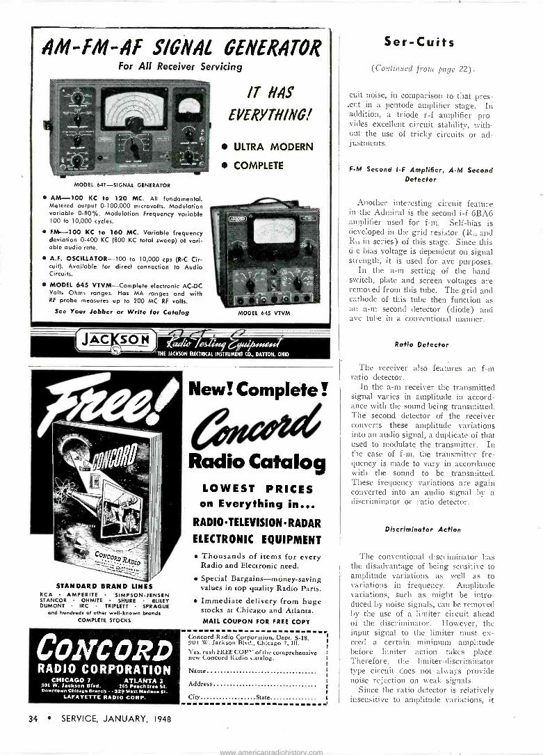
SIGNAI GENERATOR For All Receiver Servicing
MODEL 641-SIGNAL GENERATOR
AM -100 KC to 120 MC. All fundamental. Metered output 0-100,000 microvolts. Modulation variable 0-80%. Modulation Frequency variable 100 to 10,000 cycles.
FM -100 KC to 160 MC. Variable frequency deviation 0-400 KC (800 KC total sweep) at vari- able audio rate.
A.F. OSCILLATOR -100 to 10,000 cps (R -C Cir- cuit). Available for direct connection to Audio Circuits.
MODEL 645 VTVM-Complete electronic AC -DC Volts Ohms ranges. Has MA ranges and with RF probe measures up to 200 MC RF volts.
See Your Jobber or Write for Catalog
IT HAS
EVERYTHING!
ULTRA MODERN
COMPLETE
MODEL 645 VTVM
,1AC SO N Rl7Llì / ' THE JACKSON ELECTRICAL INSTRUMENT CO., DAYTON, OHIO
STANDARD BRAND LINES RCA AMPERITE SIMPSON-JENSEN STANCOR OHMITE SHURE BLILEY DUMONT IRC TRIPLETT SPRAGUE
and hundreds of other well-known brands COMPLETE STOCKS
CONCORD RADIO CORPORATION
CHICAGO 7 ATLANTA 3 901 W. Jackson Blvd. 265 Peachtree St. Downtown Chicago Branch - . 229 West Madison St.
LAFAYETTE RADIO CORP.
New! Complete!
Radio Catalog LOWEST PRICES on Everything in...
RADIO TELEVISION RADAR
ELECTRONIC EQUIPMENT
Thousands of items for every Radio and Electronic need.
Special Bargains-money-saving values in top quality Radio Parts.
Immediate delivery from huge stocks at Chicago and Atlanta. MAIL COUPON FOR FREE COPY
Concord Radio Corporation, Dept. S-18, 901 W. Jackson Blvd., Chicago 7, 111.
Yes, rush FREE COP" of the comprehensive new Concord Radio catalog.
Name..
Address
City State
Ser -Cuits
(Continued from page 22).
cuit noise, in comparison to that pres- ent in a pentode amplifier stage. In addition, a triode r -f amplifier pro- vides excellent circuit stability, with- out the use of tricky circuits or ad- justments.
F -M Second I -F Amplifier, A -M Second Detector
Another interesting circuit feature in the Admiral is the second i -f 6BA6 amplifier used for f -m. Self -bias is developed in the grid resistor (Rt5 and R. in series) of this stage. Since this d -c bias voltage is dependent on signal strength, it is used for avc purposes.
In the a -m setting of the band - switch, plate and screen voltages are removed from this tube. The grid and cathode of this tube then function as an a -m second detector (diode) and avc tube in a conventional manner.
Ratio Detector
The receiver also features an f -m1
ratio detector. In the a -m receiver the transmitted
signal varies in amplitude in accord- ance with the sound being transmitted. The second detector of the receiver converts these amplitude variations into an audio signal, a duplicate of that used to modulate the transmitter. In the case of f -m, the transmitter fre- quency is made to vary in accordance with the sound to be transmitted. These frequency variations are again converted into an audio signal by a discriminator or ratio detector.
Discriminator Action
The conventional discriminator has the disadvantage of being sensitive to amplitude variations as well as to variations in frequency. Amplitude variations, such as might be intro- duced by noise signals, can be removed by the use of a limiter circuit ahead of the discriminator. However, the input signal to the limiter must ex- ceed a certain minimum amplitude before limiter action takes place. Therefore, the limiter -discriminator type circuit does not always provide noise rejection on weak signals.
Since the ratio detector is relatively insensitive to amplitude variations, it
34 SERVICE, JANUARY, 1948
www.americanradiohistory.com
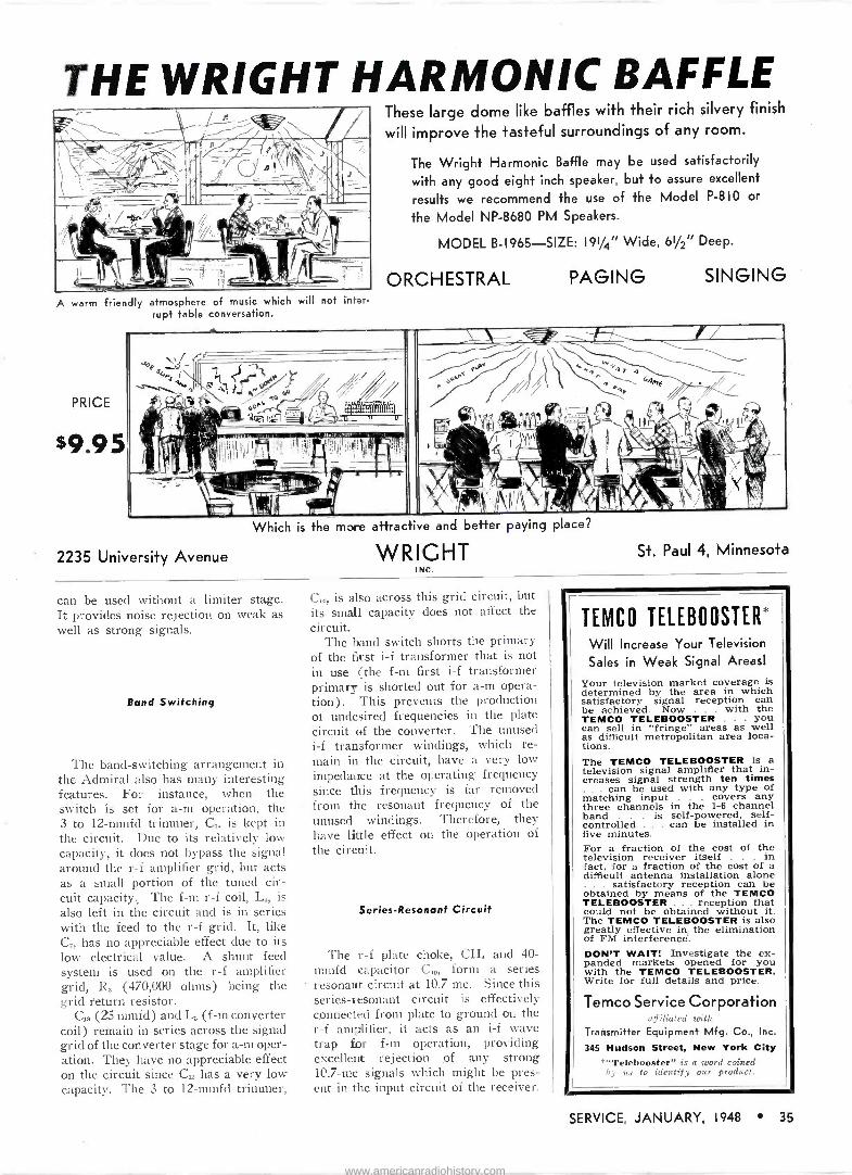
THE WRIGHT HARMONIC BAFFLE
A warm friendly atmosphere of musk which will not inter- rupt table conversation.
PRICE
$9.95
These large dome like baffles with their rich silvery finish
will improve the tasteful surroundings of any room.
The Wright Harmonic Baffle may be used satisfactorily
with any good eight inch speaker, but to assure excellent
results we recommend the use of the Model P-810 or
the Model NP -8680 PM Speakers.
MODEL B-1965-SIZE: 191/4" Wide, 61/2" Deep.
ORCHESTRAL PAGING SINGING
+!i 1 . ` =t \,/
PJ ` a 1}. \14e
I Fd1 / 4Pi r a
1t tJ «so rA %/^j/ / 1\
e oe^` . `" ,. y #
1 e ' °- ` ¿'r'.°'.!1 1, : Ili i
11._ \,-., rl ... ,. y , .. i t( . á _Iy ç
I P, II -ilt; 1 n+ a I i 1 ;, r d' p 4, é, \ I ll i, 1 _ `
:: T_ a` \,14,
\ ``'
\ I i "i.. * \, \ , `tl
..u.r.t IU ,L. a = t yry: - _7 JJxxx p 1 \\ i{}; 1- i_"-'f'', T
` ¡' .111{. i i. ` II I 1\
41, i .s 1.. /, 6;;'. ( \
2235 University Avenue
l Which is the more attractive and better paying pace
WRIGHT INC.
St. Paul 4, Minnesota
can be used without a limiter stage. It provides noise rejection on weak as well as strong signals.
Bond Switching
The band -switching arrangement in the Admiral also has many interesting features. For instance, when the switch is set for a -m operation, the 3 to 12-mmfd trimmer, C,, is kept in the circuit. Due to its relatively low capacity, it does not bypass the signal around the r -f amplifier grid, but acts as a small portion of the tuned cir- cuit capacity., The f -ni r -f coil, L,, is also left in the circuit and is in series with the feed to the r -f grid. It, like C,, has no appreciable effect due to its low electrical value. A shunt feed system is used on the r -f amplifier grid, Rs (470,000 ohms) being the grid return resistor.
Cis (25 mmfd) and Ls (f -in converter coil) remain in series across the signal grid of the converter stage for a -m oper- ation. They have no appreciable effect on the circuit since Cu has a very low capacity. The 3 to 12-mmfd trimmer,
is also across this grid circuit, but its small capacity does not affect the circuit.
The band switch shorts the primary of the first i -f transformer that is not in use (the f -m first i -f transformer primary is shorted out for a -m opera- tion). This prevents the production of undesired frequencies in the plate circuit of the converter. The unused i -f transformer windings, which re- main in the circuit, have a very low impedance at the operating frequency since this frequency is far removed from the resonant frequency of the unused windings. Therefore, they have little effect on the operation of the circuit.
Series -Resonant Circuit
The r -f plate choke, CH, and 40- mmfd capacitor Cis, form a series resonant circuit at 10.7 mc. Since this series -resonant circuit is effectively connected from plate to ground on the r -f amplifier, it acts as an i -f wave trap for f -ni operation, providing excellent rejection of any strong 10.7 -mc signals which might be pres- ent in the input circuit of the receiver.
TEMCO TELEBOOSTER*
Will Increase Your Television
Sales in Weak Signal Areas!
Your television market coverage is determined by the area in which satisfactory signal reception can be achieved. Now . with the TEMCO TELEBOOSTER . you can sell in "fringe" areas as well as difficult metropolitan area loca- tions. The TEMCO TELEBOOSTER is a television signal amplifier that in- creases signal strength ten times
can be used with any type of matching input . covers any three channels in the 1-6 channel band . is self -powered, self- controlled . can be installed in five minutes. For a fraction of the cost of the television receiver itself . in fact, for a fraction of the cost of a difficult antenna installation alone
. satisfactory reception can be obtained by means of the TEMCO TELEBOOSTER . reception that could not be obtained without it. The TEMCO TELEBOOSTER is also greatly effective in the elimination of FM interference. DON'T WAIT! Investigate the ex- panded markets opened for you with the TEMCO TELEBOOSTER. Write for full details and price.
Temco Service Corporation affiliated witl,
Transmitter Equipment Mfg. Co., Inc.
345 Hudson Street, New York City "Telebooster" is a word coined by us to identify our product.
SERVICE, JANUARY, 1948 35
www.americanradiohistory.com
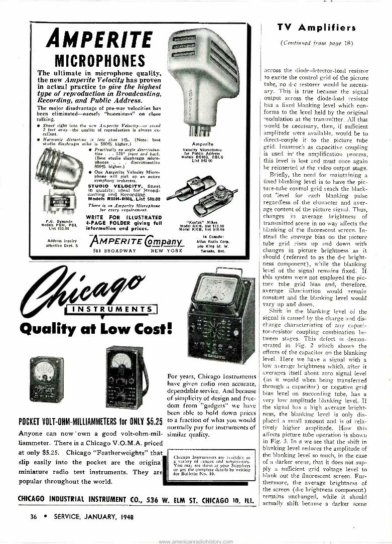
AMPERITE MICROPHONES
The ultimate in microphone quality, the new Ainperite Velocity has proven in actual practice to give the highest type of reproduction in Broadcasting, Recording, and Public Address. The major disadvantage of pre-war velocities has been eliminated-namely "boominess" on close talking.
Shout right into the new Amperite Velocity-or stand 2 feet away-the quality of reproduction is always ex- cellent. Harmonic distortion is less than 1%. (Note: best studio diaphragm mike is 500% higher.)
Practically no angle discrimina- tion . . . 120° front and back. (Best studio diaphragm micro- phones . . . discrimination 800% higher.) One Amperite Velocity Micro- phone will pick up an entire symphony orchestra.
STUDIO VELOCITY, finest in quality; ideal for Broad- casting and Recording. Models R80H-R80L.List $80.00 There is an Amperite Microphone
for every requirement.
WRITE FOR ILLUSTRATED 4 -PAGE FOLDER giving full information and prices.
P.G. Dynamic Models PGH, PGL
List $32.00
Address inquiry attention Dept. S
Amperite Velocity Microphones for Public Address
Models RBHG, RBLG List $42.00
"Kontak" Mikes Model SKH, list $12.00 Model KKH, list $18.00
AMPER/TE emPany_ 561 BROADWAY NEW YORK
In Canada: Atlas Radio Corp. 560 King St. W.
Toronto, Ont.
INSTRUMENTS
Quality at Low Cost!
POCKET VOLT-OHM-MILLIAMMETERS for ONLY $5.25
Anyone can now ' own a good volt-ohm-mil- liammeter. There is a Chicago V.O.M.A. priced at only $5.25. Chicago "Featherweights" that slip easily into the pocket are the original miniature radio test instruments. They are popular throughout the world.
For years, Chicago Instruments have given radio men accurate, dependable service. And because of simplicity of design and free- dom from "gadgets" we have been able to hold down prices to a fraction of what you would normally pay for instruments of similar quality.
Chicago Instruments are available in a variety of ranges and sensitivities. You may see them at your Suppliers or get the complete details by writing for Bulletin No. 10.
CHICAGO INDUSTRIAL INSTRUMENT CO., 536 W. ELM ST. CHICAGO 10. ILL
TV Amplifiers (Continued from page 18)
across the diode -detector -load resistor to excite the control grid of the picture tube, no d -c restorer would be necess- ary. This is true because the signal output across the diode -load resistor has a fixed blanking level which con- forms to the level held by the original modulation at the transmitter. All that would be necessary, then, if sufficient amplitude were available, would be to direct -couple it to the picture tube grid. Inasmuch as capacitive coupling is used in' the amplification process, this level is lost and must once again be reinserted at the video output stage.
Briefly, the need for maintaining a fixed blanking level is to have the pic- ture -tube control grid reach the black- out level for each blanking pulse regardless of the character and aver- age content of the picture signal. Thus, changes in average brightness of transmitted scene in no way affects the blanking of the fluorescent screen. In- stead the average bias on the picture tube grid rises up and down with changes in picture brightness as it should (referred to as the d -c bright- ness component), while the blanking level of the signal remains fixed. If this system were not employed the pic- ture tube grid bias and, therefore, average illumination would remain constant and the blanking level would vary up and down.
Shift in the blanking level of the signal is caused by the charge and dis- charge characteristics of any capaci- tor -resistor coupling combination be- tween stages. This defect is demon- strated in Fig. 2 which shows the effects of the capacitor on the blanking level. Here we have a signal with a low average brightness which, after it averages itself about zero signal level (as it would when being transferred through a capacitor) or negative grid bias level on succeeding tube, has a very low amplitude blanking level. If the signal has a high average bright- ness, the blanking level is only dis- placed a small amount and is of rela- tively higher amplitude. How this affects picture tube operation is shown in Fig. 3. In a we see that the shift in blanking level reduces the amplitude of the blanking level so much, in the case of a darker scene, that it does not sup- ply a sufficient grid voltage level to blank out the fluorescent screen. Fur- thermore, the average brightness of the screen (d -c brightness component) remains unchanged, while it should actually shift because a darker scene
36 SERVICE, JANUARY, 1948
www.americanradiohistory.com
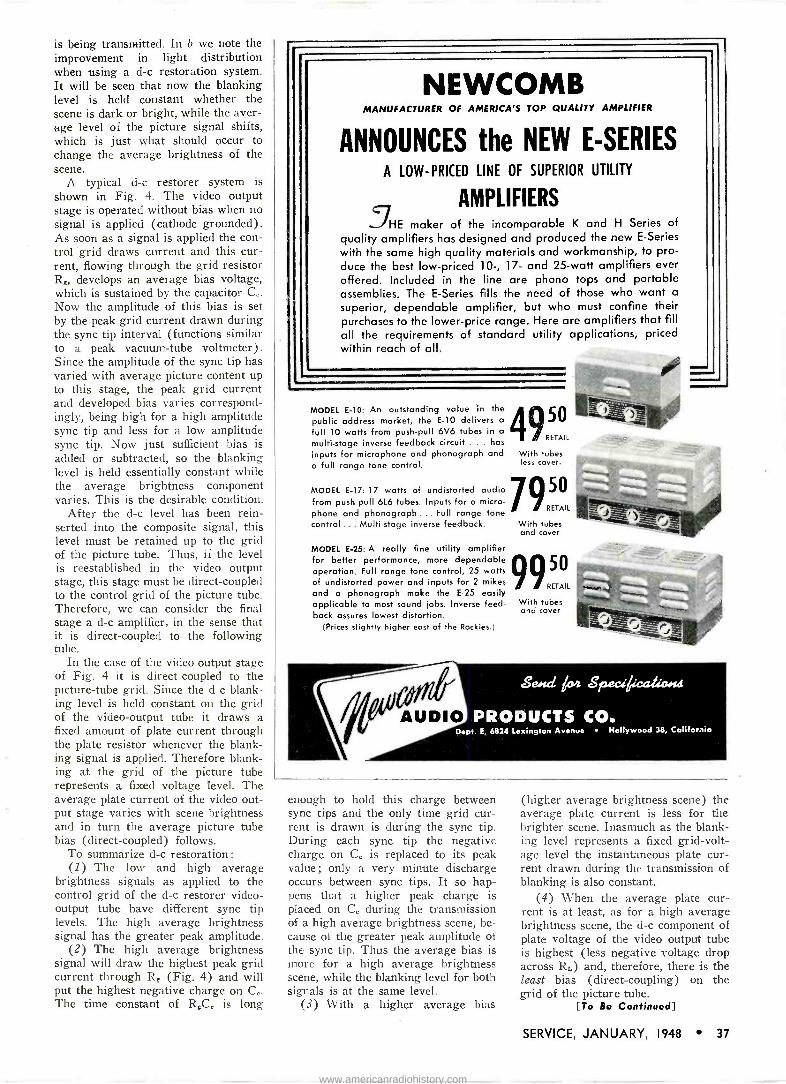
is being transmitted. In b we note the improvement in light distribution when using a d -c restoration system. It will be seen that now the blanking level is held constant whether the scene is dark or bright, while the aver- age level of the picture signal shifts, which is just what should occur to change the average brightness of the scene.
A typical d -c restorer system is shown in Fig. 4. The video output stage is operated without bias when no signal is applied (cathode grounded). As soon as a signal is applied the con- trol 'grid draws current and this cur- rent, flowing through the grid resistor R. develops an average bias voltage, which is sustained by the capacitor C.. Now the amplitude of this bias is set by the peak grid current drawn during the sync tip interval (functions similar to a peak vacuum -tube voltmeter). Since the amplitude of the sync tip has varied with average picture content up to this stage, the peak grid current and developed bias varies correspond- ingly, being high for a high amplitude sync tip and less for a low amplitude sync tip. Now just sufficient bias is
added or subtracted, so the blanking level is held essentially constant while the average brightness component varies. This is the desirable condition.
After the d -c level has been rein- serted into the composite signal, this level must be retained up to the grid of the picture tube. Thus, if the level is reestablished in the video output stage, this stage must be direct -coupled to the control grid of the picture tube. Therefore, we can consider the final stage a d -c amplifier, in the sense that it is direct -coupled to the following tube.
In the case of the video output stage of Fig. 4 it is direct -coupled to the picture -tube grid. Since the d -c blank- ing level is held constant on the grid of the video -output tube it draws a fixed amount of plate current through the plate resistor whenever the blank- ing signal is applied. Therefore blank- ing at the grid of the picture tube represents a fixed voltage level. The average plate current of the video out- put stage varies with scene brightness and in turn the average picture tube bias (direct -coupled) follows.
To summarize d -c restoration: (1) The low and high average
brightness signals as applied to the control grid of the d -c restorer video - output tube have different sync tip levels. The high average brightness signal has the greater peak amplitude.
(2) The high average brightness signal will draw the highest peak grid current through R, (Fig. 4) and will put the highest negative charge on C,,. The time constant of R.C. is long
NEWCOMB MANUFACTURER OF AMERICA'S TOP QUALITY AMPLIFIER
ANNOUNCES the NEW E -SERIES A LOW-PRICED LINE OF SUPERIOR UTILITY
AMPLIFIERS HE maker of the incomparable K and H Series of
quality amplifiers has designed and produced the new E -Series
with the same high quality materials and workmanship, to pro- duce the best low-priced 10-, 17- and 25 -watt amplifiers ever offered. Included in the line are phono tops and portable assemblies. The E -Series fills the need of those who want a
superior, dependable amplifier, but who must confine their purchases to the lower -price range. Here are amplifiers that fill all the requirements of standard utility applications, priced within reach of all.
MODEL E-10: An outstanding value in the 4 / public address market, the E-10 delivers a j full 10 watts from push-pull 6V6 tubes in a
multi -stage inverse feedback circuit ... has RETAIL
inputs for microphone and phonograph and a full range tone control.
MODEL E-17: 17 watts of undistorted audio from push-pull 616 tubes. Inputs for a micro- phone and phonograph ... Full range tone control ... Multi -stage inverse feedback.
MODEL E-25: A really fine utility amplifier for better performance, more dependable operation. Full range tone control, 25 watts of undistorted power and inputs for 2 mikes and a phonograph make the E-25 easily applicable to most sound jobs. Inverse feed- back assures lowest distortion.
(Prices slightly higher east of the Rockies.)
AUDIO
With tubes less cover.
7950
RETAIL
With tubes and cover
9 50
RETAIL
With tubes and cover
Send 104 s,.eciAcaliciAut
PRODUCTS CO. Dept. E, 6824 Lexington Avenue Hollywood 38, California
enough to hold this charge between sync tips and the only time grid cur- rent is drawn is during the sync tip. During each sync tip the negative charge on C. is replaced to its peak value; only a very minute discharge occurs between sync tips. It so hap- pens that a higher peak charge is placed on C. during the transmission of a high average brightness scene, be- cause of the greater peak amplitude of the sync tip. Thus the average bias is more for a high average brightness scene, while the blanking level for both signals is at the same level.
(3) With a higher average bias
(higher average brightness scene) the average plate current is less for the brighter scene. Inasmuch as the blank- ing level represents a fixed grid -volt- age level the instantaneous plate cur- rent drawn during the transmission of blanking is also constant.
(4) When the average plate cur- rent is at least, as for a high average brightness scene, the d -c component of plate voltage of the video output tube is highest (less negative voltage drop across RL) and, therefore, there is the least bias (direct -coupling) on the grid of the picture tube.
[To Be Continued]
SERVICE, JANUARY, 1948 37
www.americanradiohistory.com

Precision Built for Precision Work . ._
VACO Break -proof, Shock -proof
Screw and Nut Drivers
Top quality in tools has always been a "must" in radio. Only precision built equipment prevents burred screw slot edges ... provides sureness in making delicate ad- justments . . . draws metal or wood firmly together. Break -proof, shock -proof Vaco drivers are your assurance of the right tool for the job. Write for descriptive cata- log, today. Vaco Products Co., 317 E. Ontario St., Chi- cago 11, III. 173 TYPES AND SIZES
NEW... Colored Spin -Hex Handle Caps
Developed by Vaco to end confusion of similar sizes, speed up production. Color of cap indicates size of driver.
Two GREAT
OHM CHEST with 100 Insulated Resistors
This handsome Chest has 20 compartments, 10 in the base and 10 in a removable tray. Walnut fin- ish; brass hinges and fastener. Contains 100 re- sistors stamped with resistance values, 5 ohms to 20 megohms, '/r watt to 2 wafts, color coded. Every size is popular!
$ 95
COMPLETE
Send for our FREE
MONTHLY BARGAIN BULLETIN
with each Ohm 7,Ze Chest ordered, you
get our "Resist -O -Guide" free. Revolving wheels in
color show all resistance values.
B B7 Bti - B1111 BBf Send me at $4.95. Send me _ Cap Chests with 27 "Akrad" Condensers in each at $9.95.
D I enclose $
Olson pays the postage.
MONEY -SAVERS
CAP CHEST with 27 "Akrad" Condensers
A terrific buy! We want you to try the amazing new Olson "Akrad" Condensers, so we pack 27 "Akrads" (a $31.45 List Value) in a beautiful walnut -finish wood chest with hinged lid and 6 compartments - and send you the whole works for only $9.95. Wowl Order now! CONTENTS:
QUAN. CAP. VOLTAGE LIST TOTAL 2 10 25 - $0.75 81.50
25 .85 1.70 5 20_ 150 .95 4.75 5 40 150 1.10 5.50 4_20-20 150 1.30 - 5.20 5 8 450__ .95 4.75
16 450 1.35- 5.40 Walnut Finished Chest 2.65 _ 2.65
TOTAL, 831.45 $095 COMPLETE
GUARANTEE Use 5 Olson "Akrads." If for any reason you are not
satisfied, you can return the rest with Cap Chest and get back the $9.95
and postage.
@e! 01I.mµ4r _ . Clesi! .Ceri! : t
C%t Ct-irCrX _41Le:,
MI BM IMO NM MI ME MI IBM IMO IMIO IMO BM In _ Ohm Chests with 100 Insulated Resistors in each,
I 1
NAME
Send my order C.O.D. I will pay the postage.
(Plea. Print)
ADDRESS (PI..,. Print)
CITY STATE ma mom BBB M----- MI ti---- MMMM--BBt BM
38 SERVICE, JANUARY, 1948
VECTOR -PHASE BOOK PUBLISHED BY RIDER
A pocket -sized book, Understanding Vectors and Phase by John F. Rider and Seymour D. Uslan, has been published by John F. Rider Publisher, Inc., 404 Fourth Ave., New York 16, N. Y.
Availabl`. in two editions, one paper- bound at 99 cents, the other cloth bound al $1.89.
* * *
SYLVANIA APPOINTS ZIMMER V -P IN CHARGE OF OPERATIONS
H. Ward Zimmer, former vice-presi- dent in charge of the radio tube division, Sylvania Electric Products Inc., has been appointed vice president in charge of manufacturing operations for all company divisions.
* * *
WARD LEONARD CATALOG
A catalog, 1)-30, describing vitroilur rheostats and resistors, and amateur re- lays has been published by the radio and electronic distributor division, Ward Leonard Electric Company, 53 W. Jack- son Blvd., Chicago 4, Illinois. Informa- tion covers ring type and heavy duty plate type rheostats, and the following types of resistors ; fixed tubular, adjust - ohm, stripohm, plaque, non -inductive, discohm, line voltage reducers, and flu- orescent lamp resistors. Presented are dimensional data and basic resistor form- ulas.
Amateur relays described include types for antenna, r -f break-in, band switching, keying, overload, time delay, safety, sen- sitive, latch -in, and remote control.
HYTRON TUBE TAPPER
Tube tapper, in the form of a pencil, recently announced by Hytron.
www.americanradiohistory.com
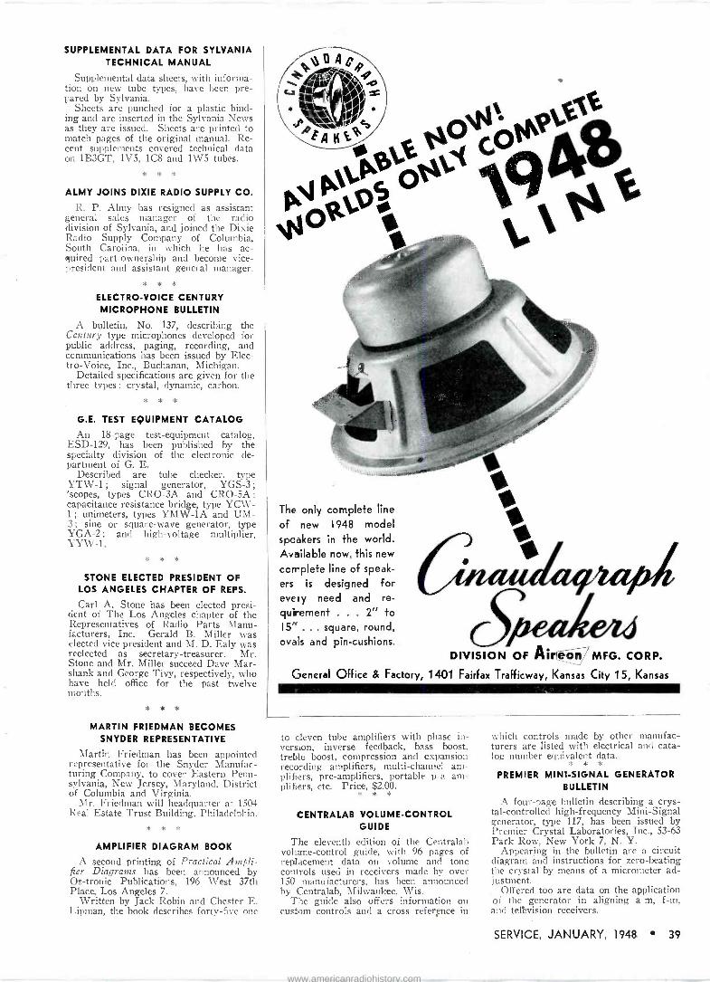
SUPPLEMENTAL DATA FOR SYLVANIA TECHNICAL MANUAL
Supplemental data sheets, with informa- tion on new tube types, have been pre- pared by Sylvania.
Sheets are punched for a plastic bind- ing and are inserted in the Sylvania News as they are issued. Sheets are printed to match pages of the original manual. Re- cent supplements covered technical data on 1B3GT, 1V5, 1C8 and 1W5 tubes.
* * *
ALMY JOINS DIXIE RADIO SUPPLY CO.
R. P. Almy has resigned as assistant general sales manager of the radio division of Sylvania, and joined the Dixie Radio Supply Company of Columbia, South Carolina, in which he has ac- quired part -ownership and become vice- president and assistant general manager.
* *
ELECTRO -VOICE CENTURY MICROPHONE BULLETIN
A bulletin, No. 137, describing the Century type microphones developed for public address, paging, recording, and communications has been issued by Elec- tr o -Voice, Inc., Buchanan, Michigan.
Detailed specifications are given for the three types : crystal, dynamic, carbon.
* * *
G.E. TEST EQUIPMENT CATALOG
An 18 -page test -equipment catalog, ESD-129, has been published by the specialty division of the electronic de- partment of G. E.
Described are tube checker. type YTW-1 ; signal generator, YGS-3 ;
'scopes, types CRO-3A and CRO-5A ;
capacitance resistance bridge, type YCW- 1 ; unimeters, types YMW-1A and UM - 3 ; sine or square -wave generator, type Y GA -2 ; and high -voltage multiplier, YYW-1.
* * *
STONE ELECTED PRESIDENT OF LOS ANGELES CHAPTER OF REPS.
Carl A. Stone has been elected presi- dent of The Los Angeles chapter of the Representatives of Radio Parts Manu- facturers, Inc. Gerald B. Miller was elected vice president and M. D. Ealy was reelected as secretary -treasurer. Mr. Stone and Mr. Miller succeed Dave Mar - shank and George Tivy, respectively, who have held office for the past twelve months.
* * *
MARTIN FRIEDMAN BECOMES SNYDER REPRESENTATIVE
Martin Friedman has been appointed representative for the Snyder Manufac- turing Company, to cover Eastern Penn- sylvania, New Jersey, Maryland, District of Columbia and Virginia.
Mr. Friedman will headquarter at 1504 Real Estate Trust Building, Philadelphia.
* * *
AMPLIFIER DIAGRAM BOOK
A second printing of Practical Ampli- fier Diagrams has been announced by Os-tronic Publications, 196 West 37th Place, Los Angeles 7.
Written by Jack Robin and Chester E. Lipman, the book describes forty-five one
The only complete line
of new 1948 model
speakers in the world. Available now, this new
complete line of speak-
ers is designed for every need and re- quirement . . . 2" to 15" ... square, round, ovals and pin -cushions.
DIVISION OF Aireon MFG. CORP.
General Office & Factory, 1401 Fairfax Trafficway, Kansas City 15, Kansas
to eleven tube amplifiers with phase in- version, inverse feedback, bass boost, treble boost, compression and expansion recording amplifiers, multi -channel am- plifiers, pre -amplifiers, portable p -a am- plifiers, etc. Price, $2.00.
* * *
CENTRALAB VOLUME -CONTROL GUIDE
The eleventh edition of the Centralab volume -control guide, with 96 pages of replacement data on volume and tone controls used in receivers made by over 150 manufacturers, has been announced by Centralab, Milwaukee, Wis.
The guide also offers information on custom controls and a cross reference in
which controls made by other manufac- turers are listed with electrical and cata- log number equivalent data.
*
PREMIER MINI -SIGNAL GENERATOR BULLETIN
A four -page bulletin describing a crys- tal -controlled high -frequency Mini -Signal generator, type 117, has been issued by Premier Crystal Laboratories, Inc., 53-63 Park Row, New York 7, N. Y.
Appearing in the bulletin are a circuit diagram and instructions for zero -beating the crystal by means of a micrometer ad- j ustment.
Offered too are data on the application of the generator in aligning a -m, f -m, and tellvision receivers.
SERVICE, JANUARY, 1948 39
www.americanradiohistory.com
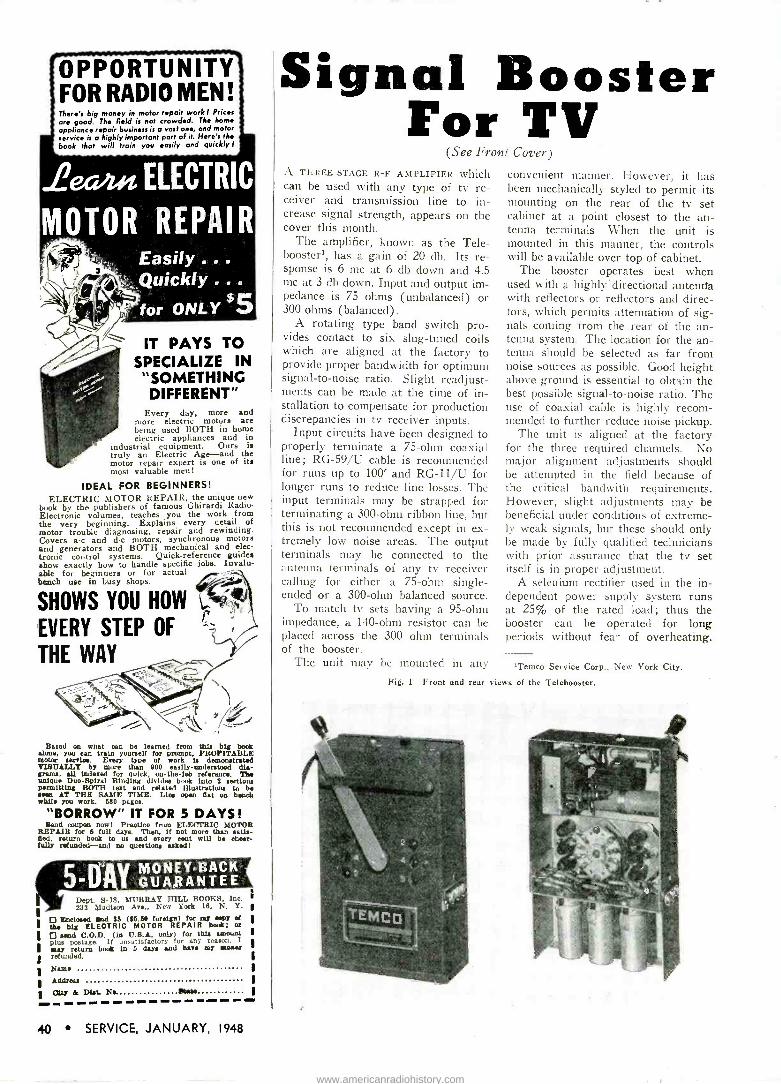
OPPORTUNITY FOR RADIO MEN! There's big money in motor repair work I Prices are good. The field is not crowded. The home appliance repair business is a vast one, end motor service is a highly important part of it. Here's the book that will train you easily and quickly !
L?ecm.n. ELECTRIC
MOTOR REPAIR Easily ... Quickly for ONLY
$5
IT PAYS TO SPECIALIZE IN "SOMETHING DIFFERENT"
Every day, more and more electric motora are being used BOTH in home electric appliances and in
industrial equipment. Ours is truly an Electric Age --and the motor repair expert is one of its most valuable men!
IDEAL FOR BEGINNERS! ELECTRIC MOTOR REPAIR, the unique new
book by the publishers of famous Ghirardi Radio - Electronic volumes, teaches you the work from the very beginning. Explains every detail of motor trouble diagnosing, repair and rewinding. Covers a -c and d -c motors, synchronous motors and generators and BOTH mechanical and elec- tronic control systems. Quick -reference guides show exactly how to handle specific jobs. Invalu- able for beginners or for actual bench use in busy shops.
SHOWS YOU HOW !-' EVERY STEP OF -7
THE WAY
Based on what oan be learned from Shia big book alone, you can train yourself for prompt, PROFITABLE motor service. Every type of work U demonstrated VISUALLY by more than 900 euliy-understood dia- grama, all indexed for quirk, on -the -lob reference. The unique Dus -Spiral Binding divides book into 2 sections permitting BOTH text and related illustrations to be seen AT THE SAME TIME. Lies open Oat on bench while you work. 580 pages.
"BORROW" IT FOR 5 DAYS! fiend coupon now! Practice from ELECTRIC MOTOR
REPAIR for 6 full days. Then, If not more than satis- fied, return book to us and every mot will be cheer- fully refunded-and no questions ukedl
Dept, S-18, MURRAY HILL BOOKS, Inc. 238 Madison Ave New York 10, N. Y.
0 Ilhoelosed fhd $5 ($8.80 foreign) fer my eey et the big ELECTRIC MOTOR REPAIR leek; or 0 send C.O.D. (in U.S.A. only) for this amount plus postage. If unsatisfactory for any reason, I nay return book in 5 days and han m7 as0aey refunded.
Name
Address
dtf & DLL No. Stan asen ..... a_ ..... s_ eee ee,
Signal Booster For TV
(See Front Cover)
A THREE -STAGE R -F AMPLIFIER which can be used with any type of tv re- ceiver and transmission line to in- crease signal strength, appears on the cover this month.
The amplifier, known as the Tele- boosterl, has a gain of 20 db. Its re- sponse is 6 me at 6 db down and 4.5 me at 3 db down. Input and output im- pedance is 75 ohms (unbalanced) or 300 ohms (balanced).
A rotating type band switch pro- vides contact to six slug -tuned coils which are aligned at the factory to provide proper bandwidth for optimum signal-to-noise ratio. Slight readjust- ments can be made at the time of in- stallation to compensate for production discrepancies in tv receiver inputs.
Input circuits have been designed to properly terminate a 75 -ohm coaxial line; RG -59/U cable is recommended for runs up to 100' and RG -11/U for longer runs to reduce line losses. The input terminals may be strapped for terminating a 300 -ohm ribbon line, but this is not recommended except in ex- tremely low noise areas. The output terminals may be connected to the antenna terminals of any tv receiver calling for either a 75 -ohm single - ended or a 300 -ohm balanced source.
To match tv sets having a 95 -ohm impedance, a 140 -ohm resistor can be placed across the 300 ohm terminals of the booster.
The unit may be mounted in any
convenient manner. However, it has been mechanically styled to permit its mounting on the rear of the tv set cabinet at a point closest to the an- tenna terminals. When the unit is mounted in this manner, the controls will be available over top of cabinet.
The booster operates best when used with a highly' directional antenna with reflectors or reflectors and direc- tors, which permits attenuation of sig- nals coming from the rear of the an- tenna system. The location for the an- tenna should be selected as far from noise sources as possible. Good height above ground is essential to obtain the best possible signal-to-noise ratio. The use of coaxial cable is highly recom- mended to further reduce noise pickup.
The unit is aligned at the factory for the three required channels. No major alignment adjustments should be attempted in the field because of the critical bandwith requirements. However, slight adjustments may be beneficial under conditions of extreme- ly weak signals, but these should only be made by fully qualified technicians with prior assurance that the tv set itself is in proper adjustment.
A selenium rectifier used in the in- dependent power supply system runs at 25% of the rated load; thus the booster can be operated for long periods without fear of overheating.
'Temco Service Corp., New York City.
Fig. 1. Front and rear views of the Telebooster.
40 SERVICE, JANUARY, 1948
www.americanradiohistory.com

WHY SHOULD YOU
BUY QUAM
TRADE MARI(
SPEAKERS ?
Stability-Reliability Quam has been making speakers for almost a quarter century, and today is one of America's oldest and largest speaker manufac- turers.
No "Distress" Speakers
QUAM replacement speakers are designed and buil+ as such. QUAM does not unload speakers to the jobber that are rejected by manufacturers. Every Quam speaker is guaranteed exactly as represented.
Superior Engineering The QUAM ADJUST -A -CONE SPEAKER with its adjustable voice coil, precision centered at the factory, and its efficient U -Shaped Coil Pot is among the finest on the market - an out- standing contribution to speaker design.
You can't go wrong when you specify QUAM ADJUST -A -CONE SPEAKERS.
LOOK FOR THE
U -SHAPED COIL POT
Quarr deij age
SPEAKERS
QUAM NICHOLS COMPANY
Cottage Grove at 33rd Place Chicago 16, III.
New Products BRACH NEON POCKET TESTER
A neon pocket tester, Test -O -Lite, im- proved by the use of Koroseal leads, has been announced by L. S. Brach Mfg. Corp., 200 Central Ave., Newark 4, N. J. The contact points of the leads are "not needle-sharp and cannot pierce pocket.
Test -O -Lite, originated by Brach in 1929, is capable of detecting the presence of current from 90 to 500 volts a -c or d -c, and able to distinguish between the live wire and ground, and on d -c to determine the polarity of the circuit.
Can be used for the location of blown fuses, .determination of faults in electrical circuits, etc.
Has a resistor in each lead to elimi- nate any possible danger of flash -over on circuits in excess of 220 volts.
* * *
ELECTRIC AUTO -LITE SUPPRESSOR -TYPE SPARK PLUG
The development of a spark pine with a built-in 10,000 -ohm resistor to suppress spark plug interference has been an- nounced by the Electric Auto -Lite Com- pany, Toledo 1, Ohio.
* * *
NATIONAL POLYTRONICS WIRE RECORDER
A wire recorder, model 5-A, with self contained amplifier and microphone, has been developed by National Tolytronics, Inc., 2430 Atlantic Ave., Brooklyn. N. Y.
* * *
CAMCO DIPOLES AND REFLECTORS
Dipoles and reflectors for f -m and tv coverage have been announced by Cam - burn, Inc., 32-40 57 Street, Woodside, N. Y.
Antenna -reflector combination is said to provide a 5 -db increase in signal strength with a 15 -db rejection of inter- fering signals.
Reflector kits supplied with folded or straight dipoles.
(Continued on page 42)
Servicemen's choice! in
For 32 years, Cunninghams have carried New York State on a plat- form of quality and performance. That's why your customers are can- didates for Cunninghams . . . why Cunninghams should be your choice.
See your CUNNINGHAM DISTRIBUTOR
DYMAC, Inc. Buffalo BARCLAY-NEW YORK, Inc. . . New York ROCHESTER RADIO SUPPLY CO.,
Rochester
CITY ELECTRIC CO., Inc. Syracuse
QiinninghamTubes A product of
RADIO CORPORATION OF AMERICA
Harrison, N. J.
SERVICE, JANUARY, 1948 41
www.americanradiohistory.com

EASILY ADJUSTABLE FOR THE JOB
ADJUSTOHM RESISTORS Seven Stock Sizes from 10 watts to 200 watts
Send for Catalog D-30
Gives handy data and Information on various types of Resistors and Rheostats avail- able from stock.
You can often save time, work and money by using WARD LEONARD ADJUSTOHMS. Re- sistance can immediately be adjusted to the value you need . . . or tapped . . . on the job. Besides .
you know these Resistors will give the finest service because they are WARD LEONARD quality. Available from Authorized Distributors Everywhere
WARD LEONARD ELECTRIC CO. 53E W. Jackson Blvd., Chicago 4
Radio and Electronic Distributor Division
WARP LEONARD RELAYS RESISTORS RHEOSTATS
Electric control devices since 1892
ESICO CG. U. 5. °wT. OiF.
For the Service Man who demands a good rugged tool and the very best value for his money, ESICO is the answer. Twenty years of steady repeat business from production line users, vouch for this statement. Get the most for your money, insist on ESICO.
Available at All Good Distributors ELECTRIC SOLDERING IRON CO., INC.
3148 West Elm St., Deep River, Conn.
2emonieftwx_ SPEAKERS 'YOUR JOBBER CAN SUPPLY YOU!
Permotlux quality and dependability-the same as supplied to the major set manufacturers-is your assurance of com- plete customer satisfaction. You'll find Perniollux Speakers easy to install and readily available in both PM and Electro- dynamic types. You'll find too, that it pays to give your cus- tomers "tops in tone" with a Permoflux Replacement Speaker.
TWO COMPLETE PERMFLUX FACTORIESRIESTOTO SERVE YOU FL fREFWRITE BULLETINFOR
PIONEER MANUFACTURERS OF PERMANENT MAGNET DYNAMIC TRANSDUCERS
PERMOFLUX CORPORATION 4900 WEST GRAND AVE., CHICAGO 39, ILLINOIS
236 SOUTH VERDUGO ROAD, GLENDALE 5, CALIFORNIA
New Products {,continued from page 41)
STEPHENS CO -SPIRAL SPEAKER
A co -spiral speaker, model P-52FR, with a differential diffuser, which is said to provide high -frequency dispersion with an almost 100% spherical polar pattern of over 90°, has been announced by the Stephens Manufacturing Corporation, 10416 National Blvd., Los Angeles 34, California.
Frequency range is said to be from 40 to 14,000 cycles.
Supplied in both 12" and 15" cone diameters. Efficiency of over 50% said to be available with either 8- or 16 -ohm voice coils ; 15 watts of power input handling capacity.
Bulletin 109 contains complete data. * * *
PRECISION APPARATUS ELECTRONAMIC TESTER
A tube, battery and circuit tester, series 10-54 Electrorurnsic Test Master, has been announced by the Precision Apparatus Co., Inc., 92-27 Horace Hard- ing Blvd., Elmhurst, L. I.
Tube tester has a twelve -element cen- tral -lever -selector system, free -point ele- ment short -check and performance test selection regardless of varying or mul- tiple pin and cap termination ; standard tube basing numbering system on all element selectors; brass geared test data roll chart and dual short -check sensitiv- ity.
Circuit and battery testing section af- fords: 35 a -c and d -c ranges to 6000 volts, 60 microamperes, 12 amperes, -I- 70 db, 60 megohms. Meter sensitivity is 20,000 ohms per volt d -c, 1000 ohms per volt a -c.
Available in three basic models: 10-54-P, portable ; 10-54-C, sloping counter -type ; 10 -54 -PM, standard rack - panel.
i;ltjE;ijF;ñ,F
TACO OMNIDIRECTIONAL TV 'F -M ANTENNA
An omnidirectional S -folded dipole antenna, type 624, has been announced by Technical Appliance Corporation of Sherburne, N. Y.
Dipole, which can be used for f -m and tv, made from %" diameter non -corros -
42 SERVICE, JANUARY, 1948
www.americanradiohistory.com
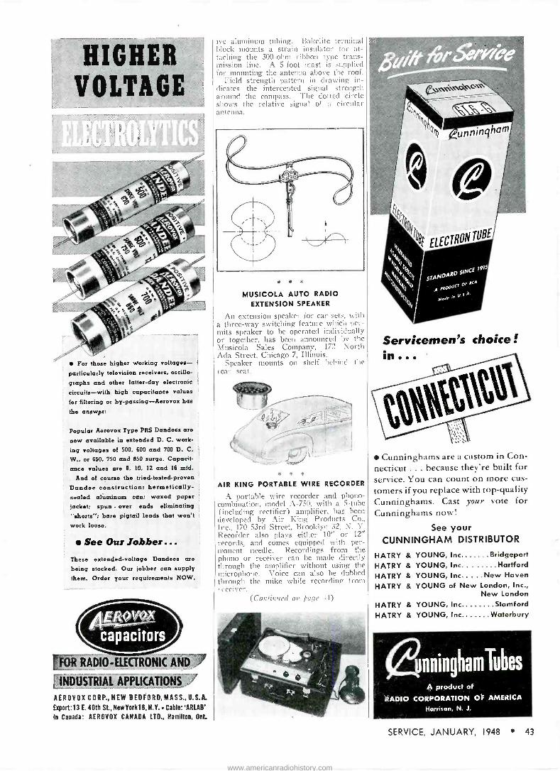
HIGHER VOLTAGE
For those higher Working voltages- particularly television receivers, oscillo -
graphs and other latter-day electronic
circuits-with high capacitance values for filtering or by-passing-Aerovox has the answer:
Popular Aerovox Type PRS Dandees are
now available in extended D. C. work-
ing voltages of 500, 600 and 700 D. C.
W., or 650. 750 and 850 surge. Capacit- ance values are 8, 10, 12 and 16 mfd.
And of course the tried -tested -proven Dundee construction: hermetically - sealed aluminum can; waxed paper jacket; spun - over ends eliminating
"shorts'; bare pigtail leads that won't work loose.
See Our Jobber... These extended -voltage Dandees are being stocked. Our jobber can supply them. Order your requirements NOW.
OR RADIO -ELECTRONIC AND INDUSTRIAL APPLICATIONS !'
AEROVOX CORP.,NEW BEDFORD,MASS.,D.S.A.
Export:13 E. 40th St, New York 16, N.Y. Cable: 'ARLAB'
In Canada: AEROVOX CANADA LTD., Hamilton, Ont.
ive aluminum tubing. Bakelite terminal block mounts a strain insulator for at- taching the 300 -ohm ribbon type trans- mission line. A 5 -foot mast is supplied for mounting the antenna above the roof.
Field strength pattern in drawing in- dicates the intercepted signal strength around the compass. The (lotted circle shows the relative signal of a circular antenna.
* * *
MUSICOLA AUTO RADIO EXTENSION SPEAKER
An extension speaker for car sets, with a three-way switching feature which per- mits speaker to be operated individually or together, has been announced by the Musicola Sales Company, 172 North Ada Street, Chicago 7, Illinois.
Speaker mounts on shelf behind the rear seat.
* * *
AIR KING PORTABLE WIRE RECORDER
A portable wire recorder and phono - combination, model A-750, with a 5 -tube (including rectifier) amplifier, has been developed by Air King Products Co., Inc., 170 53rd Street, Brooklyn 32, N. Y. Recorder also plays either 10" or 12" records, and comes equipped with per- manent needle. Recordings from the phono or receiver can be made directly through the amplifier without using the microphone. Voice can also be dubbed through the mike while recording from receiver.
(Continued on page 44)
e»rr\-(s.etG
Servicemen's choice!
Cunninghams are a custom in Con- necticut ... because they're built for service. You can count on more cus-
tomers if you replace with top-quality Cunninghams. Cast your vote for Cunninghams now!
See your CUNNINGHAM DISTRIBUTOR
HAIRY & YOUNG, Inc. Bridgeport
HAIRY & YOUNG, Inc... Hartford HATRY & YOUNG, Inc.....New Haven HAIRY & YOUNG of New London, Inc.,
New London Stamford
HATRY & YOUNG, Inc. Waterbury HAIRY & YOUNG, Inc.
ßnninghamTubes A product of
RADIO CORPORATION OF AMERICA
Harrison, N. J.
SERVICE, JANUARY, 1948 43
www.americanradiohistory.com

Here's how
can help you plan
..WITH LESS POWER!
University speak- ers require min- imum amplifier power. Having a higher conver- sion efficiency, they deliver more acoustic output per watt input, thon any other speaker of comparable size and weight.
(A tee OA S
ON MAN
Paa'na and announungl
Same at above, but d.
ion 360°
vaco and ° °'° bui d'tt°bu
of above.
1 3 wan to 1000
A 1t
QUICKER... AT LOWER COST! The logical approach to any sound system plan- ning problem is to first select the speaker or speakers capable of proper coverage and quality of reproduction. Once the speakers have been decided upon, the selection of the correct size amplifier becomes a routine matter of totalling the powers required for the individual speakers. The many UNIVERSITY speakers now avail- able readily solve this problem. Included are speakers for every class of service-low power, super power, directional, radial, explosion -proof, submergence -proof, high fidelity, paging talk - back and others.
SPEAKER
TODAY FOR THIS HANDY
CHART - NO OBLIGATION! WRITE
OBLIGATION! çP agas
SELECTION 204110N (neeaox)
aPP(ICAiION
OEFI(ES
SIMS 5105AGE
S10(Á a00MS
EAC100.15 Aa
light otumsis re OA IN WON SAN Some
UNIVERSITY ITYLOUDSPEAKERS, LOUD SP EAV
EpS, INC./ ee 1111111 SW OR
1911 It ion 360°
BO Kensi Avenue, While Plains,N.
SPEAA9 MODE(
MN OA ,BB
IBA
ABPe
B' S
IN 51MN» xtA
Paa'n9 and annoumeN Sub
worn`
e shut lot
low
,peoleelt m inlet worn
temi bui d,tmbu
Same at above.
non 360°
Vale and 0nmbuion
le0°
1 3 want pet 1000
to 11 MODEL IBB PRICE 534.00
MODEL SAH PRICE $37.00
Television Installation and Service will be featured in March SERVICE
Service technicians are vital in successful television merchandising
Reserve advertising space now. Last forms close March 1.
PRECISION ELECTRONICS. MODEL 250 SIGNAL TRACER
Minna
ISOLATED FROM AC LINE
with. -¢ Staoe l/Tl//jl/ arnASSEIM AC OPERATEO
raegae'
A
HEAR THE SIGNAL
SEE THE SIGNAL
LOWEST INPUT CAPACITY
SMALL EASY TO USE PROBE
ELECTRONIC VACUUM
VOLT METER- 4 STAGE
Ger
$I1495 SEE YOUR
JOBBE'
LUtC\.J\°v.JL` C`..LC\14)*VJs1W
S4\ -ö43 M\iWAVk` SAKtv'E
/ (,A1tCPG0 22,
SIGNAL TRACER SPECIALISTS
New Products (Continued from page 43)
ALTEC LANSING PORTABLE P -A AMPLIFIER
A portable 15 -watt public-address am- plifier, model A-324, has been announced by Altec Lansing Corporation, 250 West 57th St., New York 19, N. Y.
Frequency range said to be 35 to 12,000 cycles, within 1db.
Two of inputs provide 95 db gain for low -impedance microphones with indi- vidual volume controls on each input for mixing purposes.
Transformer in high -gain low -imped- ance microphone input circuits has 90 -db shielding to guard against hum and noise pickup.
Two other high -impedance inputs pro- vide 72 db gain for receiver or phono- graph pickup or high -impedance micro- phones; they are coupled to a dual type volume control.
* * *
CLAROSTAT CERAMIC -CASED MIDGET WIRE -WOUND RESISTORS
Ceramic -cased midget wire -wound re- sistors, Greenohm Juniors, have been an- nounced by Clarostat Mfg. Co., Inc., 130 Clinton St., Brooklyn, N. Y.
Resistors feature a wire winding on fibre -glass core, with axial bare pigtail leads clinched to the ends, placed in a steatite tube and filled and sealed with Greenohm cold -setting inorganic cement.
Standard Greenohm Junior, type C7GJ, measures 1/" long by 5/16" diameter with 2" leads. It is rated at 7 watts. Available in values from practically zero to 5000 ohms max. Smaller type, C4GJ, measures 1" long by 5/16" diameter, and is rated at 4 watts, with maximum avail- able resistance of 1000 ohms.
* * *
ACA PORTABLE MAGNETAPE RECORD- ING AND PLAYBACK INSTRUMENTS
Portable magnetic recording -playback units have been announced by the Magne - phone Division of Amplifier Corp. of America, 398-3 Broadway, New York 13, N. Y. In one model, the case houses a self-contained recording and playback unit. Another case holds a microphone, microphone cable, extension line cord and contains additional space for 25 reek of Magnetape, plus cleaning and main tenance accessories.
Four models are available, depending on the frequency response desired One model, TP -800-C, will record and play -
44 SERVICE, JANUARY, 1948
www.americanradiohistory.com
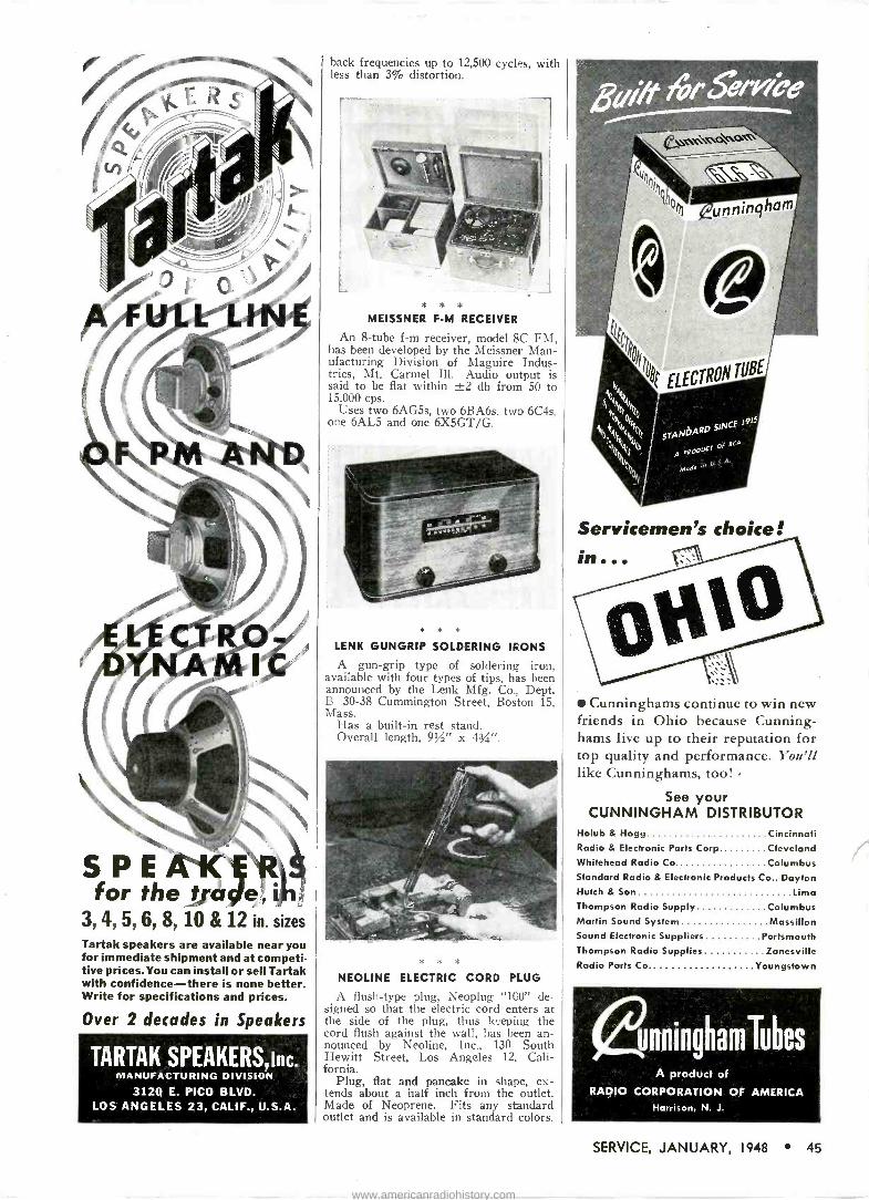
IIIIIIIIIIIWIIIIYIINI
SPE for the t III'e
mpI woI Idd
3, 4, 5, 6, 8,10 & 12 in. sizes Tartak speakers are available near you for immediate shipment and at competi- tive prices.You can install or sell Tartak with confidence-there is none better. Write for specifications and prices.
Over 2 decades in Speakers
IIIpIIIIIIuullyli
IIOIIIIIIpIIIIpIIIIIIIIIII
TARTAK SPEAKERS inc. MANUFACTURING DIVISION
3120 E. PICO BLVD. LOS ANGELES 23, CALIF., U.S.A.
back frequencies up to 12,500 cycles, with less than 3% distortion.
* * * MEISSNER F -M RECEIVER
An 8 -tube f -m receiver, model 8C FM, has been developed by the Meissner Man- ufacturing Division of Maguire Indus- tries, Mt. Carmel Ill. Audio output is said to be flat within ±2 db from 50 to 15,000 cps.
Uses two 6AG5s, two 6BA6s, two 6C4s, one 6AL5 and one 6X5GT/G.
* * *
LENK GUNGRIP SOLDERING IRONS
A gun -grip type of soldering iron, available with four types of tips, has been announced by the Lenk Mfg. Co, Dept. B 30-38 Cummington Street, Boston 15, Mass.
Has a built-in rest stand. Overall length, 9%" x 4X".
* * *
NEOLINE ELECTRIC CORD PLUG
A flush -type plug, Neoplug "100" de- signed so that the electric cord enters at the side of the plug, thus keeping the cord flush against the wall, has been an- nounced by Neoline, Inc., 130 South Hewitt Street, Los Angeles 12, Cali- fornia.
Plug, flat and pancake in shape, ex- tends about a half inch from the outlet. Made of Neoprene. Fits any standard outlet and is available in standard colors.
Servicemen's choice! in
Cunninghams continue to win new friends in Ohio because Cunning - hams live up to their reputation for top quality and performance. You'll like Cunninghams, too! -
See your CUNNINGHAM DISTRIBUTOR
Holub & Hogg Cincinnati Radio & Electronic Parts Corp Cleveland Whitehead Radio Co Columbus Standard Radio & Electronic Products Co., Dayton Hutch & Son Lima Thompson Radio Supply Columbus Martin Sound System Massillon Sound Electronic Suppliers Portsmouth Thompson Radio Supplies Zanesville Radio Parts Co. Youngstown
únninghamTubes A product of
RADIO CORPORATION OF AMERICA Harrison, N. J.
SERVICE, JANUARY, 1948 45
www.americanradiohistory.com
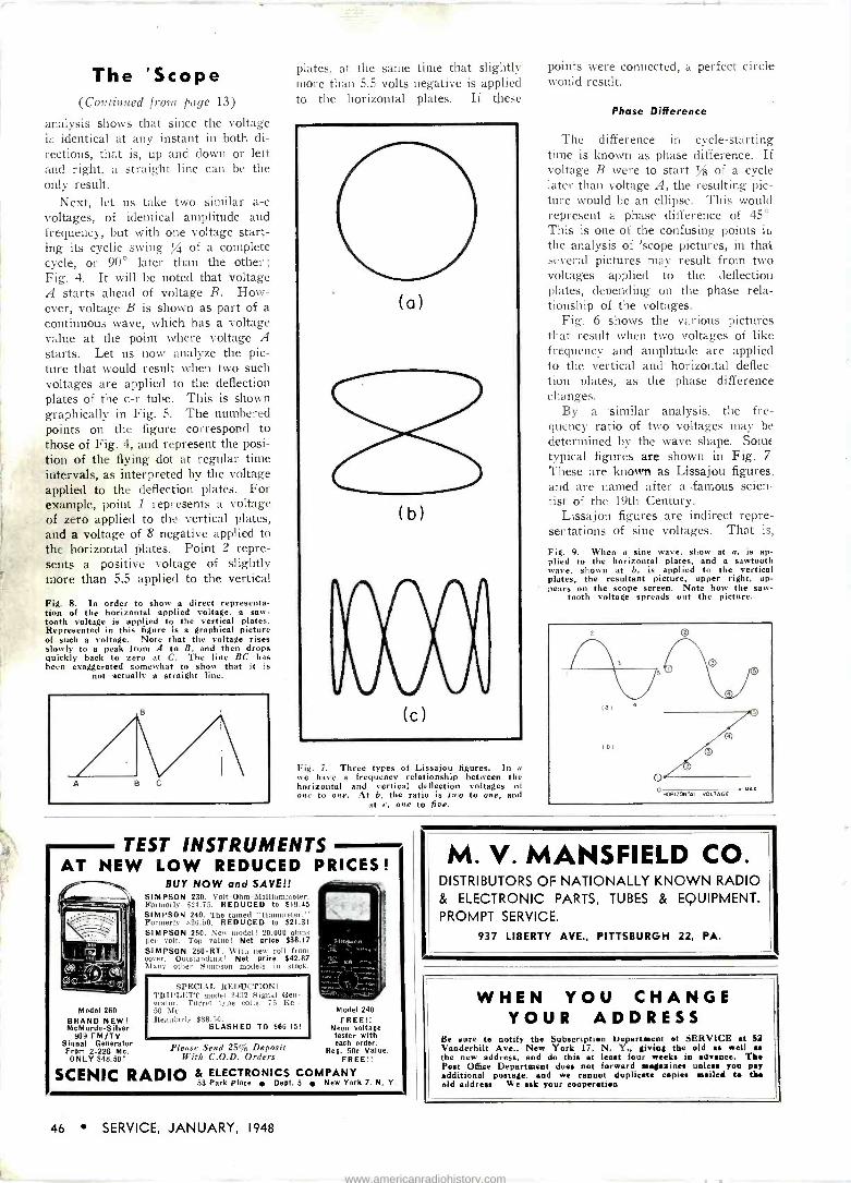
I. a
The 'Scope (Continued from page 13)
analysis shows that since the voltage is identical at any instant in both di- rections, that is, up and down or left and right, a straight line can be the only result.
Next, let us take two similar a -c voltages, of identical amplitude and frequency, but with one voltage start- ing its cyclic swing / of a complete cycle, or 90° later than the other; Fig. 4. It will be noted that voltage A starts ahead of voltage B. How- ever, voltage B is shown as part of a continuous wave, which has a voltage value at the point where voltage A
starts. Let us now analyze the pic- ture that would result when two such voltages are applied to the deflection plates of the c -r tube. This is shown graphically in Fig. 5. The numbered points on the figure correspond to those of Fig. 4, and represent the posi- tion of the flying dot at regular time intervals, as interpreted by the voltage applied to the deflection plates. Fol example, point 1 represents a voltage of zero applied to the vertical plates. and a voltage of 8 negative applied tt, the horizontal plates. Point 2 repre- sents a positive voltage of slightly more than 5.5 applied to the vertical
Fig. S. In order to show a direct representa- tion of the horizontal applied voltage, a saw - tooth voltage is applied to the vertical plates. Represented in this figure is a graphical picture of such a voltage. Note that the voltage rises slowly to a peak from A to B, and then drops quickly back to zero at C. The line BC has been exaggerated somewhat to show that it is
not actually a straight line.
plates, at the same time that slightly more than 5.5 volts negative is applied to the horizontal plates. If these
(o)
(b)
(c)
Fig. 7. Three types of Lissajou figures. In a we have a frequency relationship between the horizontal and vertical deflection voltages of one to one. At b, the ratio is two to one, and
at e, one to five.
TEST INSTRUMENTS AT NEW LOW REDUCED PRICES !
BUY NOW and SAVE!!
Model 260 BRAND NEW! McMurdo -Silver
909 FM/TV Signal Generator From 2-226 Mc.
ONLY $48.50!
SIMPSON 230. Volt-Ohm-Milliammeter. Formerly $24.75. REDUCED to $19.45 SIMPSON 240. The famed "Hammeter." Formerly $26.50. REDUCED to $21.31 SIMPSON 260. New model! 20.000 ohms j r volt. Top value! Net price $38.17 SIMPSON 260 -RT. With new roll front cover. Outstanding! Net price $42.87 Many other Simpson models in stink.
SPECIAL REDUCTION! TttIPLETT model 2432 Signal Gen- erator. Turret type coils. 75 Rc.- 7A Mc. Regularly $89.50.
SLASHED TO $66.15!
Please Send 25- Deposit With C.O.D. Orders
Model 240 FREE!!
Neon voltage tester with each order.
Reg. 50c Value. FREE!!
SCENIC RADIO & ELECTRONICS COMPANY 53 Park Place Dept. 5 New York 7, N. Y.
points were connected, a perfect circle would result.
Phase Difference
The difference in cycle -starting time is known as phase difference. If voltage B were to start / of a cycle later than voltage A, the resulting pic- ture would be an ellipse. This would represent a phase difference of 45° This is one of the confusing points ill the analysis of 'scope pictures, in that several pictures may result from two voltages applied to the deflection plates, depending on the phase rela- tionship of the voltages.
Fig. 6 shows the various pictures that result when two voltages of like frequency and amplitude are applied to the vertical and horizontal deflec- tion plates, as the phase difference changes.
By a similar analysis, the fre- quency ratio of two voltages may be determined by the wave shape. Some typical figures are shown in Fig. 7
These are known as Lissajou figures, and are named after a .famous scien- tist of the 19th Century.
Lissajou figures are indirect repre- sentations of sine voltages. That is,
Fig. 9. When a sine wave, show at a, is ap- plied to the horizontal plates, and a sawtooth wave, shown at b, is applied to the vertical plates, the resultant picture, upper right, ap- pears on the scope screen. Note how the saw -
tooth voltage spreads out the picture.
M. V. MANSFIELD CO. DISTRIBUTORS OF NATIONALLY KNOWN RADIO & ELECTRONIC PARTS, TUBES & EQUIPMENT. PROMPT SERVICE.
937 LIBERTY AVE., PITTSBURGH 22, PA.
WHEN YOU CHANGE YOUR ADDRESS
Be sure to notify the Subscription Department of SERVICE at 52 Vanderbilt Ave.. New York 17, N. Y., giving the old es well as the new address. and do this at least four weeks in advance. The Poet Office Department does not forward maguines unless you pay additional postage. and we cannot duplicate copies mailed to dub old address- V. e ask your cooperation
46 SERVICE, JANUARY, 1948
www.americanradiohistory.com

For The "Highs" In High Fidelity...
«de he rsew
UNIVERSITY TWEETER
Quick, Easy
Installation!
It's a fact! This new tweeter gives you full range reproduction right up to 15,000 cycles when used in conjunction with any standard cone speaker. Quickly attaches to the voice coil terminals of your present cone speaker through a simple, inexpensive high pass filter. Available in handsome walnut cabinet or in single or dual unit unmounted types. Prices from $20.00. For details write today to UNIVERSITY LOUDSPEAKERS, INC., 80 South Kensico Avenue, White Plains, New York.
E RADIomE ()HUE
EN YOU KNOW
Modern RADIO INSTRUMENTS
oe JUST PUBLISHED! Itere is the book every radioman needs. Brand new, up-to-the- minute. Tells all about modern radio and electrical testing equipment and how to use it. Money -making short-cuts on trouble -shooting, servicing, construction, and other jobs. Over 350 pages, 220 photos and diagrams. Covers Multipliers, Resistors,
Ohmmeters, Oscilloscopes and many others. You see actual equipment torn down in step by
step photos. All data pre -tested in the Coyne radio shops.
SEND NO MONEY Coupon is just a request to see and use this great
book for 7 days at our expense. Fill out the coupon and send it in. Then examine MODERN RADIO INSTRUMENTS for days, FREE, before deciding i
yon want t keep it. AC] NOW
COYNE ELECTRICAL & RADIO SCHOOL, Dept. 18E5, 500 S. Paulina St., Chicago 12, III. Teel Please send "Modern Radio Instruments and Testing Methods" on FREE TRIAL. If satisfied after 7 days, I will pay you $3.50 plus postage-if not, I'll return book and owe nothing. Name AGE Address City Zone . State
Check here if you want book sent -C.O.D.-you pay Postman $3.50-Coyne pays postage. Same 7 days. examination and return privilege.
the figures shown are resultants of two applied voltages. C -r tubes may be set up to give a direct representa- tion of the voltage -wave shape. This is done by applying a sawtooth wave (Fig. 8) to the horizontal deflection plates, while the unknown voltage is applied to the vertical plates.
In a sawtooth wave, the voltage rises slowly to a maximum at a uni- form rate, and then drops quite sud- denly to zero. This voltage does not alternate, but always rises in value in only one direction. An analysis of the action of this voltage is shown in Fig. 9.
To trace this analysis let us assume that the time interval required for one cycle of an a -c wave is identical to the time interval for one cycle of the sawtooth wave. The flying dot will then rise and fall on the screen as the a -c wave voltage rises and falls. How- ever, it will also respond to the saw - tooth voltage being applied to the horizontal deflection plates, and move lengthwise across the screen at a uni- form rate. When it reaches the far end of the screen, it will then suddenly return to the starting point, and trace the next a -c wave. If the time con- stant of the waves. applied to the ver- tical and horizontal plates are iden- tical, we'll have a recurrent picture on the screen, NNvhich will faithfully reproduce the a -c wave as a function of frequency and voltage.
The relationship of the sawtooth wave to the signal voltage is that of a time base. In other words, it repre- sents the time interval required for the signal voltage to pass through a complete cycle. By thus serving as a pure time function, the input signal may be represented in all its detail.
The previous examples were ideal examples, in that the frequencies and voltages were so arranged as to give the desired image. However, this is
not always the case in practice. For example, the sawtooth frequency may be one half, or twice the frequency of the incoming signal. Or, the sawtooth wave may have a voltage amplitude twice or one half the incoming signal. A third possibility is that the phase relationship between the two signals may distort the image. All of these eventualities have been foreseen and accounted for on the control panel of the 'scope.
The controls are, in the main, volt- age controls for the various elements of the c -r tube. Their effect is to pro- duce the type of picture sought, regu- late its size, and center it on the screen.
[To Be Continued]
Servicemen's choice!... for counter or window
Cunningham tubes and "Miss Cun- ningham," display top quality in this striking 8 -color easel poster measuring 2211x28[[. It's the hottest traffic stopper in years . . . designed to draw more customers to your shop.
"Miss Cunningham" is ready to do a selling job for you. ASK YOUR CUNNINGHAM DISTRIBUTOR TO SEND HER OVER.
únninghamTubes A product of
RADIO CORPORATION OF AMERICA Harrison, N. .1.
SERVICE, JANUARY, 1948 47
www.americanradiohistory.com

for the Serviceman Who
Cares about Tomorrow: CREI Offers the Modern Technical Training You Need to Qualify for the Good Job - That Can Be
YOURS Face the Future and Face the Facts. Radio is moving at a pace so fast, that it is far beyond the expectations of the most optimistic authorities a short time ago. New receivers contain phono- graph combinations, FM, standard and short wave AM. Television. Projection Television receivers employ 20,000 volt power supplies-some have in excess of 40 tubes. Two-way installations are becoming standard equipment on buses, trains, trucks and taxicabs. Many industrial plants have over 40 different electronic installations. These are the types of jobs you'll have to service from now on. It should be a timely warning to you that you must "re -tool" your technical knowledge in order to keep pace. You can increase your technical ability with the thorough, practical technical training for which thousands have enrolled with CREI since 1927. CREI home study courses in Practical Radio - Electronics and Television 'Engineering offer you the chance to acquire the profitable knowledge and ability to enable you to keep pace. You can start training right NOW in your spare time. It costs only a postage stamp and a few minutes' time to write for the interesting facts.
Veterans! CREI Is "G.I." Approved
FRF4 4 SAMPLE
ESSO v Now, see fqr yourself! Mail the coupon for free sample lesson and see how simple it is to study at home and improve your ability the CREI way.
MAIL COUPON. FOR FREE
BOOKLET & SAMPLE LESSON
Capitol Radio Engineering Institute DEPT. S.1., 16th and PARK RD., N. W. WASHINGTON 10, D. C.
Mail une ONE FREE sample lesson and j your 24 -page booklet, "CREI Training for Your Better Job in Radio Electronics." I am attaching a brief resume of my radio expe- I Hence, education and present position.
Il Check one E PRACTICAL RADIO -ELECTRONICS
!Course D PRACTICAL TELEVISION
Name
Street
City Zone State I am entitled to training under the G.I. Bill
JOTS AND FLASHES
AUTO RADIO SERVICING will be quite a factor in 1948. According to Frank W. Mansfield, director of sales research for Sylvania Electric Products, Inc., 84% of the 1947 cars are radio equipped. Auto radio production has hit a new high of approximately 2,860,000 units, a gain of approximately 265,000 over the 1941 record. It is interesting to note that in 1934 there were only 780,000 receivers in use and in 1937 there were 1,750,000 auto receivers. . . . Admiral Corpora- tion has set up a television training course for its distributors throughout the country. Ray Petersen, field service en- gineer, is directing the course. Others in charge of the course include Max Schinke, national service manager; Jos- eph Marty, assistant to the vice presi- dent in charge of the radio division and Ed Steinberg and Paul D'Arco, both of the service division.... Alfred Crossley and Associates, 549 W. Randolph Street, Chicago, have been appointed middle western representative for Clough Bren- gle. . Abner G. Updike has been named sales manager for the New Eng- land and east central states of the Mobile Communications Division of Farnsworth Television & Radio Corp. G. K. Dick- enson has been named sales manager for the west central and southwestern states.... A. E. Stevens has been named general sales manager of American Ra- dio Hardware Co., Mt. Vernon, N. Y. Mr. Stevens will also continue to serve as sales manager for Radio Essentials, Inc., which is the exclusive sales agency of ARHCO products to jobbers and dis- tributors. . .. Wilfrid Graham, formerly of the Camden office of RCA, has joined the sales staff of Morris F. Taylor Co., Silver Spring, Maryland.... Salescrest Co., 222 West Adams Street, Chicago, Illinois, has been appointed manufac- turers rep for Air King in the Illinois and southern Wisconsin area. Russell G. Akin is head of Salescrest television magnifying lens, Walco Tele - Vue -Lens, which is said to magnify a 52 -square inch area to 150 square inches, has been announced by the E. L. Cour- nand Company and is being distributed by Walco Distributing Co., 15 Exchange Place, Jersey City; Walco Sales Com- pany, 76 Franklin Street, East Orange, N. J., and the E. M. Ward Sales Co., 224 S. Michigan Avenue, Chicago. . . .
Burlingame Associates, 11 Park Place, N. Y. C., have been named representa- tives for all Vertrod Products in the New England states and New York, New Jersey, Eastern Pennsylvania, Delaware, Maryland and Washington, D. C... , G. E. has announced 52 addi- tional types of tubes which are said to be needed for repair in receivers made as far back as 1933 and 1934... , R. \V. Andrews, merchandise manager of the radio tube division of Sylvania Electric has been transferred from the Williams- port, Pa. office to the Emporium, Pa. office. . . . RCA plans to step up pro- duction of television picture tubes dur- ing 1948 in an additional plant at Lan- caster, Pa., according to L. W. Tee- garden, vice president in charge of the RCA tube department. . . . Over 10,000 attended the G. E. clinic meetings, which were held in 24 states, recently. R. D. Payne was in targe of the G. E. tour.
ADVERTISERS IN THIS ISSUE
SERVICE INDEX-JANUARY, 1948
AEROVOX CORPORATION 43 Agency: Austin C. Lescarbottra & Staff
AIR KING PRODUCTS CO., INC Agency: Myron Jonas Co.
AMPERITE CO. Agency: II. J. Gold Co.
THE ASTATIC CORPORATION Agency: Wearstler Advertising. Inc_
CAPITOL RADIO ENGINEERI IG INSTITUTE.. 48 Agency: Henry J. Kaufman S Associates
CHICAGO INDUSTRIAL INS". RUMENT CO 36 Agency: Turner Adv. Agency
CINAUDAGRAPH SPEAKERS, INC 39
Agency: Carl Lawson Adv. Co.
CLAROSTAT MFG. CO., INC 32 Agency: Austin C. Lescarboura & Staff
CONCORD RADIO CORP 34 Agency: E. H. Brown Adv. Agency
CORNELL-DUBILIER ELECTRIC CORP. Inside Front Cover
Agency: Reiss Advertisers
COYNE ELECTRICAL SCHOOL 47 Agency: The Phil Gordon Agency, Inc.
ALLEN B. DuMONT LABS., INC Agency: Austin C. Lescarboura & Staff
ELECTRIC SOLDERING IRON CO.. INC 42
GENERAL ELECTRIC CO I
Agency: Maxon, Inc.
GREYLOCK ELECTRONIC SUPPLY CO Agency: Bergman -Jarrett Co.
ILLINOIS CONDENSER CORP Agency: I{uttner & Kuttner
THE JACKSON ELECTRICAL INSTRUMENT CO. 34
P. R. MALLORY & CO., INC Agency: The Aitkin-Eynett t o
M. V. MANSFIELD CO 46
MINOR MACHINE CORP........... 32 Agency: Ellis Adv. Co.
MURRAY HILL BOOKS, INC 27, 40 Agency: The Harry P. Bridge Co.
NATIONAL RADIO INSTITUTE 23 Agency: Van Sant, Dugdale & Co., Inc.
NEWCOMB AUDIO PRODUCTS CO 37 Agency: Stevens -Hall Advertising
OHMITE MFG. CO Agency: The Fensholt Co.
OLSON RADIO WAREHOUSE, INC 38 Agency: The Jessup Adv. Co.
PARK METALWARE CO 3e Agency: Melvin F. Hall Agency. in.
PERMOFLUX CORPORATION 42 Agency: Turner Adv. Agency
PRECISION APPARATUS CO .... 5, 32 Agency: Shappe-'Jlkes, Inc.
PRECISION ELECTRONICS, INC 44 Agency: Campbell. Reynolds & Evans
QUAM NICHOLS CO 41
Agency: Triangle Adv. Agency, Inc.
RADIO CORPORATION OF AMERICA 41, 43, 45, 47. Back Cover
Agency: J. Walter Thompson Co.
JOHN F. RIDER PUBLISHER, INC 4 Agency: Lansford F. King, Advertising
SANGAMO ELECTRIC CO 19 Agency: Arthur R. Mogge, Inc.
SCENIC RADIO & ELECTRONICS CO 46
SOLAR CAPACITOR SALES CORP. Inside Back Cover
Agency: 0. S. Tyson & Co., Inc.
SPRAGUE PRODUCTS CO 7 Agency: The Harry P. Bridge Cu.
TARTAK SPEAKERS, INC 45 Agency: Sylvester-Afeeder Ads. Corp.
TEMCO SERVICE CORP 35
IHORDARSON 3 Agency: Ohio Adv. Agency
TRIPLETT ELECTRICAL INSTRUMENT CO 8 Agency: Western Adv. Agency, Inc.
UNIVERSAL GENERAL CORP 30 Agency: Gelles Adv. Agency, Inc.
UNIVERSITY LOUDSPEAKERS. INC 44, 47 Agency: George Homer Martin, Associates
U. S. TREASURY DEPT 24
VACO PRODUCTS CO 38
WRIGHT, INC. 38, 35 Agency: Duane \Vammnaker Associates
WARD LEONARD ELECTRIC CO 42 Agency: Henry B. Teplitz, Advertising
WRIGHT, INC. 30, 35 Agency: Kay Advertising. Inc.
6
36
31
33
32
30
17
2e
48 SERVICE, JANUARY, 1948
www.americanradiohistory.com

When your customers complain about intolerable interference with radio and television programs, make them cheerful again quite quickly-and put $$$ in your pockets, too!
How? Just install the proper Elim-O-Stat inter- ference filter. Solar Elim-O-Stats are simple and easy to connect, and all are moderately priced.
You will find a full line of Elim-O-Stats for all types of radios, television sets, home appliances, and fluorescent lamps in Solar's new Catalog SC -2. Get a copy from your distributor or from Solar Capacitor Sales Corp., 1445 Hudson Boulevard, North Bergen, N. J.
* T. M. ReT U. S. Pat,nt Office
RADIO INTERFERENCE FILTERS
E THAT ANNOYS? END IT WITH AN g .0..97
INTERFERENCE FILTER
Just A Few of the Filter, Shown in New Catalog SC -2'
www.americanradiohistory.com

OVERWHELM i G
Month after month, RCA Batteries continue to smash all previous sales records.
The reasons for this unprecedented acceptance are conclusive-
RCA Batteries are designed for radiomen ... to sell through radio outlets. And they're backed by the greatest name in radio-RCA.
RCA Batteries are your assurance of immediate customer acceptance and greater /profits.
SELL RCA BATTERIES -THE COMPLETE LINE FOR THE RADIO AND ELECTRONIC TRADE
Flashlight Portable A's Portable B's
Iffl11111
Portable AB's Farm A's Farm B's Farm AB's Industrial
TUBE DEPARTMENT
RADIO CORPORATION of AMERICA HARRISON,leek N. J.
www.americanradiohistory.com


![4074 Regulatury Cre#~spuc.sd.gov/commission/dockets/electric/2012/EL12-046/... · 2012. 7. 2. · MERP Rider Res Rider [] MN Mercury (Rider Amort) Mn TCR Rider SD ECR Rider SD TCR](https://img.pdfslide.us/doc/110x75/60c30ae1863f7559f046269e/4074-regulatury-crespucsdgovcommissiondocketselectric2012el12-046.jpg)