Embed Size (px)
Citation preview


Issued by Sandia National Laboratories, operated for the United States Department of Energy by Sandia Corporation. NOTICE: This report was prepared as an account of work sponsored by an agency of the United States Government. Neither the United States Gover- nment nor any agency thereof, nor any of their employees, nor any of their contractors, subcontractors, or their employees, makes any warranty, express or implied, or assumes any legal liability or responsibility for the accuracy, completeness, or usefulness of any information, apparatus, product, or process disclosed, or represents that its use would not infringe privately owned rights. Reference herein to any specific commercial product, process, or service by trade name, trademark, manufacturer, or otherwise, does not necessarily constitute or imply its endorsement, recommendation, or favoring by the United States Government, any agency thereof or any of their contractors or subcontractors. The views and opinions expressed herein do not necessarily state or reflect those of the United States Government, any agency thereof or any of their contractors.
Printed in the United States of America. This report has been reproduced directly from the best available copy.
Available to DOE and DOE contractors from Office of Scientific and Technical Information PO BOX 62 Oak Ridge, TN 37831
Prices available from (615) 576-8401, FTS 626-8401
Available to the public from National Technical Information Service US Department of Commerce 5285 Port Royal Rd Springfield, VA 22161
NTIS price codes Printed copy: A03 Microfiche copy: AO1

SAND93-2453 Unlimited Release
Printed January 1994
Distribution Category UC -235
Operational Experience and Evaluation of a Dual-Element Stretched-Membrane Heliostat
John W. Strachan Jake Van Der Geest
Solar Thermal Test Department Sandia National Laboratories
Albuquerque, New Mexico 87185
Abstract
A dual-element, stretched-membrane central receiver heliostat was designed and manufactured in 1989, by a private U.S. company engaged in the development of commercial central receiver solar technology. The two-module collector, with a collection area of 97.5 m2, extends stretched-membrane mirror technology on several fronts with face-down stow capability and a digital controller that integrates tracking and focusing control on a single programmable control board. The solar collector was installed at Sandia’s National Solar Thermal Test Facility in Albuquerque, New Mexico and evaluated over a three-and-a-half year period which ended in September 1993. The measured performance and the operational and maintenance characteristics of this commercial prototype are the subject of this report. The results of beam quality measurements, tracking repeatability tests, measurements of beam movement in elevated winds, performance tests of the focusing system, and all-day beam quality and tracking tests are presented, and we offer a detailed discussion of the knowledge gained through operation and maintenance and of the improvements made or suggested to the heliostat’s design.
‘This work was performed at Sandia National Laboratories, Albuquerque, New Mexico, and is supported by the U.S. Department of Energy under contract DE-AC04-94AL85000.
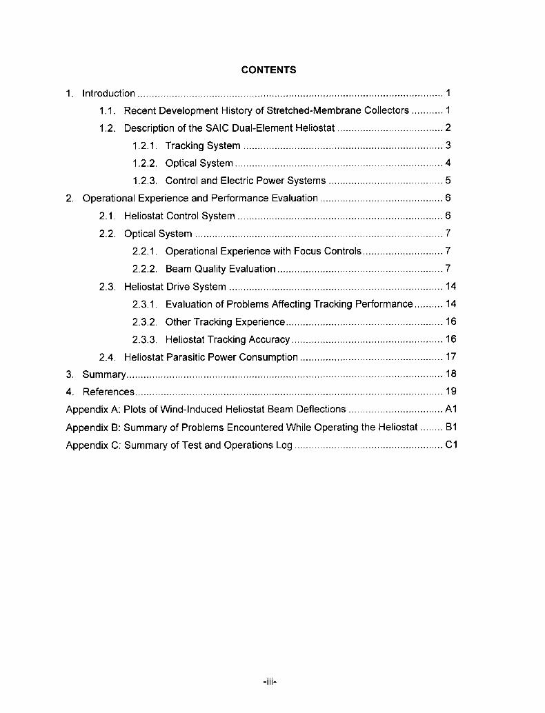
CONTENTS
1. introduction . . . . . . . . . . . . . . . . . . . . . . . . . . . . . . . . . . . . . . . . . . . . . . . . . . . . . . . . . . . . . . . . . . . . . . . . . . . . . . . . . . . . . . . . . . . . . . . . . . . . . . . . . ..l
1.1. Recent Development History of Stretched-Membrane Collectors . . . . . . . . ...1
1.2. Description of the SAIC Dual-Element Heliostat . . . . . . . . . . . . . . . . . . . . . . . . . . . . . . . . . . ...2
1.2.1. Tracking System . . . . . . . . . . . . . . . . . . . . . . . . . . . . . . . . . . . . . . . . . . . . . . . . . . . . . . . . . . . . . . . . . . . ...3
1.2.2. Optical System . . . . . . . . . . . . . . . . . . . . . . . . . . . . . . . . . . . . . . . . . . . . . . . . . . . . . . . . . . . . . . . . . . . . . . ...4
1.2.3. Control and Electric Power Systems . . . . . . . . . . . . . . . . . . . . . . . . . . . . . . . . . . . . . . . . 5
2. Operational Experience and Performance Evaluation . . . . . . . . . . . . . . . . . . . . . . . . . . . . . . . . . . . . . . . . ...6
2.1. Heliostat Control System . . . . . . . . . . . . . . . . . . . . . . . . . . . . . . . . . . . . . . . . . . . . . . . . . . . . . . . . . . . . . . . . . . . . . ...6
2.2. Optical System . . . . . . . . . . . . . . . . . . . . . . . . . . . . . . . . . . . . . . . . . . . . . . . . . . . . . . . . . . . . . . . . . . . . . . . . . . . . . . . . . . . . ...7
2.2.1. Operational Experience with Focus Controls . . . . . . . . . . . . . . . . . . . . . . . . . . . . 7
2.2.2. Beam Quality Evaluation . . . . . . . . . . . . . . . . . . . . . . . . . . . . . . . . . . . . . . . . . . . . . . . . . . . . . . . . . . 7
2.3. Heliostat Drive System . . . . . . . . . . . . . . . . . . . . . . . . . . . . . . . . . . . . . . . . . . . . . . . . . . . . . . . . . . . . . . . . . . . . . . . . . . . 14
2.3.1. Evaluation of Problems Affecting Tracking Performance . . . . . . . . . . 14
2.3.2. Other Tracking Experience . . . . . . . . . . . . . . . . . . . . . . . . . . . . . . . . . . . . . . . . . . . . . . . . . . . . . . . 16
2.3.3. Heliostat Tracking Accuracy . . . . . . . . . . . . . . . . . . . . . . . . . . . . . . . . . . . . . . . . . . . . . . . . . . . . . 16
2.4. Heliostat Parasitic Power Consumption . . . . . . . . . . . . . . . . . . . . . . . . . . . . . . . . . . . . . . . . . . . . . . . . . . 17
3. Summary . . . . . . . . . . . . . . . . . . . . . . . . . . . . . . . . . . . . . . . . . . . . . . . . . . . . . . . . . . . . . . . . . . . . . . . . . . . . . . . . . . . . . . . . . . . . . . . . . . . . . . . . . . . . . . . 18
4. References . . . . . . . . . . . . . . . . . . . . . . . . . . . . . . . . . . . . . . . . . . . . . . . . . . . . . . . . . . . . . . . . . . . . . . . . . . . . . . . . . . . . . . . . . . . . . . . . . . . . . . . . . . . . 19
Appendix A: Plots of Wind-Induced Heliostat Beam Deflections . . . . . . . . . . . . . . . . . . . . . . . . . . . . . . . . . Al
Appendix B: Summary of Problems Encountered While Operating the Heliostat . . . . . . . . BI
Appendix C: Summary of Test and Operations Log . . . . . . . . . . . . . . . . . . . . . . . . . . . . . . . . . . . . . . . . . . . . . . . . . . ..Cl
. -111-
FIGURES
Figure 1: The SAIC Dual-Element Stretched-Membrane Heliostat . . . . . . . . . . . . . . . . . . . . . . . . . . . . . . 2
Figure2: Mirror Focusing Principle of the SAIC Modules . . . . . . . . . . . . . . . . . . . . . . . . . . . . . . . . . . . . . . . . . . . . 5
Figure 3: Contour Plot of Optimal Heliostat Beam . . . . . . . . . . . . . . . . . . . . . . . . . . . . . . . . . . . . . . . . . . . . . . . . . . . . . . . 9
Figure4: All-Day Optical Petiormance . . . . . . . . . . . . . . . . . . . . . . . . . . . . . . . . . . . . . . . . . . . . . . . . . . . . . . . . . . . . . . . . . . . . . . . . 10
Figure5. Results of All-Day Beam Quality Tests . . . . . . . . . . . . . . . . . . . . . . . . . . . . . . . . . . . . . . . . . . . . . . . . . . . . . . . . 11
Figure 6: Canting-Related Mirror Pointing Error Over the Course of a Day . . . . . . . . . . . . . . . . . 12
Figure7: Wind Event Group l . . . . . . . . . . . . . . . . . . . . . . . . . . . . . . . . . . . . . . . . . . . . . . . . . . . . . . . . . . . . . . . . . . . . . . . . . . . . . . . . . . . . . 13
TABLES
Table 1: Recorded Wind-Effects Events . . . . . . . . . . . . . . . . . . . . . . . . . . . . . . . . . . . . . . . . . . . . . . . . . . . . . . . . . . . . . . . . . . . . . 13
-iv-


solar-powered electric plant in San Diego which employed point-focusing dishescomposed of 1.5-meter diameter stretched-membrane facets. In 1986, the first full-sized(50 mz) stretched-membrane heliostat mirror modules were built under contract to Sandiaby two U.S. solar technology companies, Science Applications International Corporationand Solar Kinetics Incorporated [3]. Second-generation prototype stretched-membraneheliostats were subsequently designed and manufactured by both firms between 1988 and1989.
SAIC, as part of the design effort that led to its third-generation stretched-membraneheliostat that is the subject of this report, performed a manufacturing study [4], whichproduced estimates for the cost of manufacturing the dual-element heliostat and itslifetime operation and maintenance. Based on assumed production quantities of 5,000units per year, the estimated installed cost in 1989 U.S. dollars is $107/m2 ($10/ft2) andthe Iifetim-e cost is $139/m2 ($13/ftz). This represents a reduction in cost of 20%,compared with SAIC’S estimate for the cost of the pedestal-mounted single-modulestretched-membrane heliostats.
It is interesting to compare these cost estimates to those for glass-metal heliostats.recent estimate for the installed cost of a c.iass-metal heliostat was Provided by a
A
manufacturing cost study performed in 1938 for a U.S. electric utility [5]. The installed costwas estimated at $135/m2 (also in 1989 U.S. dollars),z based on an assumed productionrate of 25,000 units at a steady rate over a ten-year period (half the rate used in SAIC’Scost study). (Estimates of operations and maintenance costs were not provided.) Onecan conclude that dual-element stretched-membrane heliostats represent a verycompetitive option to glass-metal heliostats provided that the life of reflective films can beextended or an inexpensive way devised for their periodic replacement on installedstretched-membrane heliostats.
1.2. Description of the SAIC Dual-Element Heliostat
A principle goal of SAIC’S design effort, which resulted in the dual-element stretched-membrane heliostat, was to “determine if there are cost-effective alternatives to thepedestal heliostat design and to pursue the most promising of these alternatives.” [4]One particular drawback of the pedestal-mounted single-module stretched-membrane
heliostats is their inability to stow the mirror module in the face-down orientation; thisresults in increased degradation of the reflective material, increased soiling rates, andvulnerability to hail. The guiding objectives in the design of the SAIC dual-elementstretched-membrane heliostat were to effect “cost savings in mass production andperformance improvements over current pedestal-mounted designs by allowing face-downstow, by reducing drive component costs, and by optimizing the structure for thecharacteristics of stretched-membrane heliostats.” [4]
Beninga et al. [4] provide a detailed description of the SAIC dual-element stretched-membrane heliostat, and the following description draws freely from that document.
2The utility study’s estimate was, in 1988 U.S. dollars, $131/m2, which I have converted to 1989 U.S.dollars based on the Producer Price Index for durable (non-food) consumer goods, Table B-61, page867, “Economic Report to the President Transmitted to the Congress, February, 1992,” U.S.Government Printing Office, 1992.

The rear view of the heliostat depicted in Figure 1 provides a good vantage point for itsdescription. Two 50-m2 mirror modules are mounted on a torque-tube drive assembly andeach is supported along its circumference at three equidistant points: two trusses joined tothe outer end of each of the elevation torque tubes extend to attachment brackets at theperimeter of each mirror module. A third bracket supports each mirror module andattaches directly to the torque tube. The torque tubes are attached to either side of theelevation drive, and the azimuth drive, which is located beneath the elevation drive, ismounted atop a steel-tube pedestal set in a concrete foundation.
The drives chosen for use in the dual-element heliostat are series planetary and worm-type drives manufactured by Peerless-Winsmith and powered by 1/4 HP 90VDC motors.Hall-effect encoders are incorporated into the drive motors to provide angular positionfeedback to the tracking control function. Limit switches positioned at the limits of safetravel in elevation and azimuth provide a mechanical disconnection of power to theassociated drive motor. Another set of switches provide azimuth and elevation referencepositions for the heliostat.
Each mirror module can be described as a shallow drum whose front and rear membranesare made of 0.005-inch stainless steel foil. The steel (type 201) membranes are welded toan (A500) carbon steel ring to form a closed airtight plenum. A silvered polymer reflectivefilm (ECP-305) is bonded to the front membrane to form the module’s optical (energy-reflecting) surface. To concentrate solar energy, this surface can, during on-sunoperation, be drawn into a concave, light-focusing shape by exploitation of the principle ofconstant-volume described in detail further on.
Tracking and focusing functions are micro-processor controlled; these processors andtheir associated electronics are integrated onto a single control board, which is housed ina weather-tight enclosure affixed chest-high to the heliostat pedestal. The SAIC stretched-membrane heliostat control board is one of the first prototype controllers to emerge fromthe DOE development program that integrates focus control and tracking functions in asingle control board. This heliostat controller was developed under this program expresslyfor the dual-module heliostat.
The external interface for the heliostat control board is a personal computer (PC)connected to the heliostat control board over a serial-type interface. During our evaluation,the physical separation of the control board and the PC was approximately 700 feet.
1.2.1. Tracking System
The drives of the SAIC dual-element stretched-membrane heliostat are a Peerless-Winsmith Model 1151 elevation/azimuth drive unit. Both drives consist of a first stageplanetary gear and a second stage (output) worm gear which results in a combined gearratio of 18,400:1. These drives, which are of a self-locking design, were manufactured byPeerless-Winsmith for the DOE’s second generation heliostat program; they weresubsequently employed by ARCO in heliostats and photovoltaic trackers for threecommercial applications, a solar-steam generator for enhanced oil-recovery in Taft,California, and two photovoltaic systems in California, one at Carrissa Plains and the otherat the LUGO plant north of San Bernardino. The drives are powered by 90-VDC electricmotors. They move the heliostat (in azimuth and elevation) at a rate in the range from
3

0.34°t00.370 persecond, and, during al O-hour day forthe operation, they consume580 +/- 50 WH.S
The Winsmith drives employed by the heliostat are early production units that werediscovered to have excessive play or movement between the input and output gears.Details on this are provided in the Section 2 under “Play In Azimuth Drive Gear&Resulting Drive-Motor Reversals.”
The drive controllers are a part of heliostat control board. They employ Hall-effect typeencoders to keep track of motor turns and heliostat position. Given the 18,400 -to-l gearratio of the drives, it takes 51 revolutions of the drive motor to move the heliostat 1 degree.The result is that there are 0.02° or 0.34 mr per motor revolution. The Hall-effect encoders
are mounted upon the output shafts of the drive motors and generate detectable pulses asthe motor shaft rotates, 240 pulses per full revolution of the shaft. The pulses are countedby a dedicated pulse-counter chip incorporated into the heliostat controller.
1.2.2. Optical System
The modules’ silvered reflective film maintained stable and high reflectivity during theevaluation period. The first measurement of module (solar-averaged specular) reflectivitywas made in November 1990 (a year after the installation of the heliostat); the clean-mirrormeasured reflectance at that time was 0.94 (+/- 0.015). The last measurement, made inAugust 1993, yielded a clean-mirror value of 0.93 (+/- 0.015). Thus, the degradation of thefilm’s solar-averaged specular reflectance was undetectable. The solar exposure of thereflective film during the evaluation period (three-and-a-half years) was considerably lessthan would be expected in a working heliostat field since we operated the heliostatperhaps a total of 150 days. Up until the end of the evaluation period (August 1993), therewas no observable delamination in the film’s layers, nor evidence of corrosion of the film.
One of the benefits of this heliostat’s design is its ability to be stowed face-down, whichreduces exposure of the reflective film to sunlight (particularly the degrading effects ofultraviolet sunlight), minimizes mirror soiling, and protects the reflective surface fromdamage by hailstones. By the end of the evaluation period, the numerous indentationsfrom hail evident on the rear membrane of the mirror modules provided dramatic evidenceof the value of the face-down stow.
Heliostat Focusina Mechanism
The system employed to focus the mirror modules has been patented by SAIC. Thefocusing process which is depicted in Figure 2 makes use of the fact that the plenum(volume of air) between the membranes is essentially sealed. A linear actuator, which isconnected to a pad in the middle of the rear membrane, provides the focusing action. Alinear voltage displacement transducer (LVDT), which is attached to the front membrane,measures that membrane’s position, and that measure is employed by the controller asfeedback in the focusing process.
When the linear actuator is retracted, a slight vacuum is created in the plenum betweenthe membranes, pulling the front membrane into a concave shape and focusing themodule. Likewise, extending the linear actuator pushes the rear membrane inward andcauses the front membrane to assume a convex, defocused shape. During focusing
3This information is based on measurements made during the evaluation period.
4

operations, the heliostat controller moves the linear actuator based on the position of thefront membrane as reported by the LVDT.
Since the module’s plenum is not perfectly airtight, air leaks in gradually during thefocusing operation and, in compensation for this, the linear actuator retracts the rearmembrane. Eventually the actuator shaft reaches its limit of travel and the controller canno longer maintain the focus. To reduce the plenum back to a workable volume of air thecontroller opens the module’s butterfly valve and moves the rear membrane inward to adefined position (called the neutral position). This inward movement of the rear membraneforces the expulsion of the excess air through the butterfly valve and temporarilydefocuses the module. After a suitable time delay to expel the air, the controller closesthe valve and resumes normal focusing operation. This control sequence for restoring theplenum’s air volume is called a -“burp cycle.”
Note that during on-sun operationthe heliostat would be defocusedabout l/60th of the time since the“burp” cycle takes approximately45 seconds and the intervalbetween burps is about 45minutes. In order to avoiddefocusing the beams whileexpelling excess air from theplenum, SAIC has considered mirrored surface
eliminating the focus system’sbutterfly valve and employing a fanthat would be turned on periodically to blow air from the plenum.
1.2.3. Control and Electric Power Systems
The heliostat controller and the power-processing subsystem are housed together in aweather-tight metal (type NEMA-12) enclosure mounted to the lower portion of theheliostat’s cylindrical pedestal.
The controller is a microprocessor board that incorporates control and power functions fortracking and focusing. The control board includes a Motorola 68000 microprocessor with64K of dynamic RAM and 64 K of EEPROM (programmable memory). For commercialoperation, the microprocessor is capable of being programmed to provide autonomousheliostat operation. That is, the controller need receive only high-level commands fromthe field control system; it can perform for itself ephemeris (sun-position) and trackingcalculations and can generate the command sequences to drive the heliostat’s trackingand focusing mechanisms. The control programming can be developed and compiled ona personal computer and then downloaded onto the controller’s EEPROM via a serial port.
It was SAIC’S original intent to download the C-language control program onto thecontroller, and to use a personal computer as the external interface with the controller. Asa result of a problem experienced in the downloading process, the PC was made theplatform for the control program which gives the controller its direction. SAIC eventuallysolved the problem, but time and resource constraints prevented them from rewriting thecontrol program for direct use on the controller’s processor. This is important, since someof the problems experienced with the control program, particularly its slowness of
5

operation, were due to the slowness of the PC’s processor and to the increased datatransfer requirements placed on the communications line between the controller and thePC (a serial interface that employed RS-232 and RS-422 formats).
The control board is powered with 24-VDC power which the heliostat’s power conditioningsubsystem is equipped to rectify from 11O-AC power. AC power is also rectified to provide90-VDC power to drive the 90-VDC, l/4-HP motors.
2. Operational Experience and Performance Evaluation
2.1. Heliostat Control System
The evaluation period proved invaluable as a framework for identifying problems andmaking design and component changes to the control system, particularly the heliostatcontrol board.
The control board was replaced several times over the evaluation period for a variety ofreasons. Three control boards were manufactured, and during the evaluation they wereused alternately while the current failed board was evaluated and repaired. The benefit toSAIC’S design/development effort was substantial.
There were frequent over-design currents in the drive circuitry since the drive motors drewmore current at the design load than originally specified,s and we were frequently requiredto change the drive circuit’s 10-amp fuses. On one occasion, the fusing did not preventthe failure of one of the drive circuits on the board.
Toward the end of the evaluation period we experienced a failure of the serial interfacebetween the PC and the controller. Because of the difficulty in fixing it, we simply replacedthe RS-232 interface with an RS-422 interface.
Although the menu-type design of the heliostat control program was reasonable and waswell and logically organized, using it to control the heliostat was somewhat cumbersomeand awkward, primarily because of the length of time it took to move from one part of theprogram to another. The program ran too slowly; one would expect that heliostat controlwould prove to be inadequate for emergency operation. Movement within the menus to
and from the most frequently needed heliostat commands or control actions proved to bevery slow. The program’s facility to permit the user to enter and change controlparameters is not protected against accidental entry of erroneous values. For example,one can easily, by an accidental keystroke, make a blank entry into the linear-actuatorneutral position parameter entry table and a value of O is entered, which will effectivelycripple the module’s focusing as the focus controller strives to retract the actuator past itslower limit.
In fairness, it should be noted that had the control program been implemented directly onthe control board’s own processor as originally planned, heliostat control operation would
4A “Summafy of the Problems Encountered While Operating the Heliostat” is provided in anappendix to this report as is a “Summary of the Operations and Test Log.” These are sources ofadditional details regarding the O & M experience gained with the SAIC dual-element stretched-membrane heliostat.
5SAIC did not receive the motors from the manufacturer until after the control boards had alreadybeen built.

probably have been much faster. As it was, the PC program was required to translate alluser-commands into motor-drive or other machine instructions, and this seriously boggeddown the execution time. In the commercial design this processing would take place on-board and the communication time between the PC and the controller would beconsiderably compressed.
In addition to that, the control program supplied by SAIC had many functions andcapabilities which slowed its operation that would not be included in a commercial controlprogram, but were supplied to facilitate the evaluation of the heliostat.
2.2. Optical System
2.2.1. Operational Experience with Focus Controls
Control of the mirror modules’ focusing functions is mediated by the heliostat controlprogram running on the personal computer. Adjustment of the focusing parameters isdone from within that program.
The performance characteristics of the focusing system were established by means of anumber of tests. The time required to focus and defocus the individual modules was foundto be 8 to 11 seconds; the time required to open or to close a module’s air valve wasmeasured at 7 seconds. The time required for the module to expel excess air from itsplenum (as the linear actuator pushes the rear membrane inward to the neutral position),is dependent on user-defined software parameters and ranges from 30 to 45 seconds.
When the various software parameters that govern focusing were set properly, themodules were able to maintain their focus for 25 to 55 minutes before a burp cyclebecame necessary.
The adjustment of focus parameters (from within the control program) proved to be difficultto master, and at times we were unsuccessful in obtaining a good focus. At times and forreasons that were not apparent, our focusing adjustments resulted in very short burpcycles. The fact that different units are employed within the control program to displayLVDT and the linear actuator positions contributed to the difficulties.
On several occasions when the focusing parameters were improperly set, the controlsystem got stuck in a loop in which the controller would repeatedly attempt to drive therear membrane past its forward or rear limit of travel. We were never able to identify theprecise cause of this problem. However, when properly adjusted, the focusing subsystemperformed acceptably, producing a well-focused beam.
Some mechanical problems were encountered with the focusing subsystem during theevaluation period. The LVDT’S mechanism was found to be vulnerable to moisture if notproperly sealed after maintenance. On one occasion a linear actuator stuck in its fullyretracted position and had to be replaced. On a separate occasion the over-temperaturecut-off switch of the electronic actuator for the air valves on one of the modules wastripped and remained closed. The module was unable to focus, and it took a long time todiscover the problem because we believed the heliostat control program was accuratelydisplaying the status of the valves (open or closed) of the valve. In fact, the focuscontroller does not sense valve position but displays the condition to which it hascommanded the valve.
7

2.2.2. Beam Quality Evaluation
The term “beam quality” refers to the optical performance characteristics of a solarcollector. The optical performance of the SAIC dual-element heliostat was evaluatedusing a beam characterization system (termed the BCS), which is a flux measurementsystem developed at Sandia’s National Solar Thermal Test Facility [6]. A single BCSmeasurement is made by capturing and digitizing an image of the collector beam while it isbeing tracked on a large, fixed, flat target located on the vertical north-facing wall of the(test facility’s) solar tower. The target is a white Lambertian (diffusely reflective) surfacethat reflects the beam uniformly. As a result, the distribution of light intensities in theimage captured by the BCS camera is linearly proportional to the collector flux distributionitself. There is a flux gauge embedded in the target that provides a single absolutemeasure of flux intensity at one point in the beam. When analyzing the BCS image, thisflux measure is employed to obtain an approximate flux conversion factor so that the pixellevels in the BCS image can be converted into flux intensity levels.
The BCS produces flux maps of a solar collector beam with a resolution as good as 1YO
and a measurement uncertainty of 5% or less for the relative flux distribution. Theaccuracy of the BCS’S measures for the absolute flux level at any point in the beam is 6%
at best and as good as 15% in most cases. This error estimate applies to flux levels atany particular point in the beam as well as to the total power in it. The measurement errorvaries depending on a range of variables [6], though the greatest error source is themeasurement uncertainty of the flux gauges.
The system’s image analysis capabilities make it a useful tool for examining and analyzingmany aspects of solar collector performance, including dynamic effects over the course ofa day or during windy conditions.
The BCS does not provide a measure of collector slope error,G but the collector’s opticalperformance can be modeled (using HELIOS) [7]. By comparing the actual flux map ofthe beam of a single stretched-membrane module with that predicted by the model, oneobtains an estimate of the combined effect of average surface slope error and small-scalesurface errors. That procedure was employed in the evaluation of the SAIC dual-elementstretched-membrane heliostat and produced an estimated value of 0.8 mr for thesecombined mirror slope errors for a single module.T We made no uncertainty analvsis ofthese results nor obtained a second, inde~endent measure or estimate that could beemdoved for comparison. Nonetheless, the estimate does provide an indication of thatthe collector surface slope errors are well below the DOE program’s second generationheliostat specifications, which specify the theoretical beam shape plus a 1.4 mr fringe orerror [2].
Sample Measurement of Beam Produced by O~timallv-Canted Mirror Modules
The focusing subsystem demonstrated the capability of producing well-focused, high-quality beams. The heliostat’s noontime performance on day 224 in 1992 is depicted
‘The combined effect of average (root mean squared) surface slope error and small-scale slopeerrors (sometime referred to as “waviness”).
71n HELIOS, for single heliostat modeling, the input parameter is the overall collector slope error andis intended to include mirror-module pointing error. Thus, for this analysis we modeled just a one ofthe modules and fixed the pointing error at zero.
8

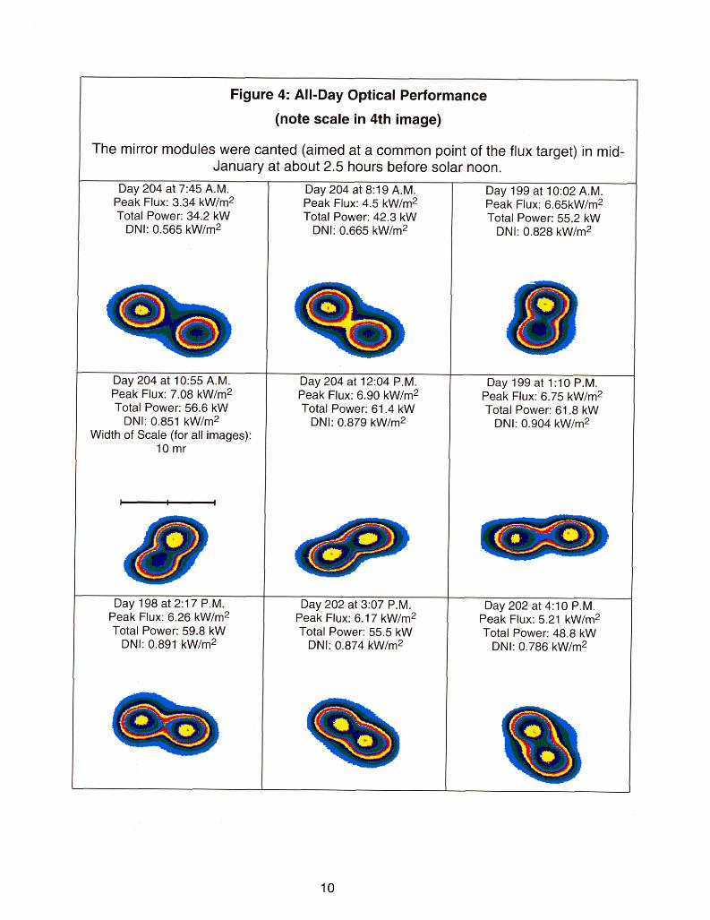


solar noon in mid-January of 1991. The consequences of this non-optimal canting wereevident when the all-day beam quality test was performed in mid-July 1992. The modulebeams did not overlap one another (Figure 4) and the peak flux levels observed (Figure 5)corresponded to the flux produced by a single module.
To gauge the significance of the canting issue, an assessment was made of beamseparation during the all-day tests and the results are plotted in Figure 6. Over the courseof a (composite) day, the beam separation was smallest several hours before and aftersolar noon. More significantly, the beam divergence increased in intervening four-hourinterval by 4.6 mr. In other words, had the beam divergence been zero at 10 a.m. and 2p.m., then the maximum beam divergence would have occurred at noon and would havehad a magnitude of 4.6 mr. This result does not quantify with any precision the year-longaverage beam divergence that can be expected in a two-module heliostat, but it doesprovide a single sample of the approximate scale of the problem.
Some small deflection of the SAIC module support structure at increased heliostatelevation angles is possible, and we performed no experiments to eliminate this as apossible contributor to module beam separation. Because of the structural efficiency ofthe module support trusses, we believe this effect would be minor or undetectable.
Attention will have tobe given to the canting
Figure 6: Canting-Related Mirror Pointing Error
strategy for dual-element stretched-membrane heliostatsin order to minimizethe pointing error dueto a fixed canting. Ananalysis of this issueis recommended andcould be performedusing a heliostatmodeling tool such asHELIOS. If that t
Over the Course of a Day
Date of Test: late July, 1992Mirror modules canted in mid Jan. 91(2-3 hr before solar noon)
4.6mr = observed increase in beam divergence
analysis should OJ 1
indicate the need, a -6 -5 -4 -3 -2 -1 0 1 2 3 4
means (manual orHours from Solar Noon
motor-driven) of 1
adjusting the module aim points could be incorporated into the heliostat’s design.
O~tical Performance Under Wlndv Conditions
Elevated winds can be expected to have two effects on the heliostat’s optical performance,one due to the deflection of the solid members (the module support structure, the gear boxand the heliostat foundations) and the other due to the deflection of the module (thesupport ring and the flexible reflective membrane itself). Deflection of the solid membersappeared to be the dominant cause of wind-induced beam movement and is what wemeasured. Our examination of the wind effects test data for evidence of module ring andsurface deflection proved inconclusive.
12

Wind-Induced Beam Deflection
During the evaluation of the SAIC dual-element stretched-membrane heliostat, windeffects tests were performed as wind conditions gave opportunity. As a result, twenty-three wind events were recorded, each consisting of a sequential series of BCS images ofthe heliostat solar beam on the BCS target.g The events recorded the motion of theheliostat beam on the receiver target during average wind speeds ranging from 13 to 31mph. Images of the beam on the target were acquired at a rate of 0.1 seconds per imagein either full-resolution mode which yielded 48 images (a 4.8 second period) or in half-resolution mode which yielded 200 images (a 20 second period).lo The peak-to-meanratio (the ratio of peak wind velocity to average wind velocity) in these observed eventsranged as high as 1.36 but in only four events was the ratio greater than 1.3. The windspeed and wind direction (at a height of 10 m) were measured concurrently with thecapture of each image, and the heliostat’s elevation and azimuth position were recorded topermit computation of the wind’s angle of attack. The angle of attack in this contextmeans the angle between the normal to the heliostat collection surface and the direction ofthe wind. To facilitate a qualitative review of the events, they were grouped by angle ofattack (AOA), as per Table 1.
I Table 1: Recorded Wind-Effects Events IAngle of Attack
(degrees)
29°-34°
38°-45°
80°-91°
112°-1230
126°-144°
Wind Speed Number of Largest AverageRange Recorded Beam Deflection(mph) Wind Events Observed (mr)
15-28 I f3 I 2.018-31 5 2.5
ILargest
Observed BeamDeflection (mr)
7.6
8.5
4.7 I
3.4 I
5.5
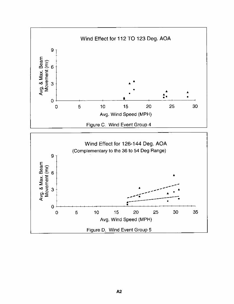
Figure 7 graphs the increase in heliostat beam deflection with wind velocity. The angle ofattack of the wind for these four observations was between 29° and 34°. The plots of theremaining four wind groups are provided for reference in an appendix to this report.
In all of the plots, the triangular data symbols represent the maximum beam deflection (inmilliradians) observed during the wind event, while the square symbols represent theaverage deflection during the event. The straight lines are linear curve fits of the beamdeflections. The decision to use a straight line fit rather than a second-order fit wasarbitrary. No attempt was made to curve-fit the data in the 112° to 123° AOA rangebecause, for that collection of observations, there was no observable relation between thebeam deflections and the recorded wind speed.
‘Performance of this test required not only elevated winds but also sunny conditions so that heliostatbeam motion on the target could be recorded with the Beam Characterization System’s camera.
10 The maximum capacity of the image digitizer board’s memory for full and half-resolution images is48 and 200 images, respectively.
13

Wind Effect for 29-34 Deg. AOA
F 9.0 ~
E Maximum observed .
cl)>
~ . . . ..”~”””””””’2 6“0 -gcOE~- Average observedc
3.0-6~
“--% ‘G-
8 0.01 I
o 5 10 15 20 25
Avg. Wind Speed (MPH)
Figure 7: Wind Event Group 1
Measurements of the total effects of structural deflection under windy conditions suaaeststhat the SAIC heliostat conforms to the second generation heliostat specification [2fl~which proscribes a maximum wind-induced deflection of the reflective surface of 3.6 mrRMS in a 27 MPH wind. Only once (in a 25-mph wind with an AOA of 33°) was theaverage beam deflection observed to exceed 3.6 mr, and during that event the averagedeflection was 3.73 mr. The average beam deflection observed in all the events recordedin the 25 to 31 mph range (there were seven of them) was 1.9 mr.
Effects of Elevated Winds on the Stretched-Membrane Collector Surface
Unlike glass mirror modules, stretched-membranes can be deformed elastically. Weevaluated the heliostat beam image data obtained during wind events and found evidenceof only minor distortions of the membrane. But the conditions of the test did not permit us
to easily quantify these findings nor permit us to draw conclusions. The existing windeffects data possibly retains some uncovered information regarding this effect.
11 Its worth noting, however, that these specifications, written before the advent of the streched-membrane type heliostats, cannot be readily applied to them.
14

2.3. Heliostat Drive System
2.3.1. Evaluation of Problems Affecting Tracking Performance
Three characteristics of the tracking subsystem were found to interact in a synergisticfashion to produce extremely large tracking errors12 over the course of only a few hours ofon-sun tracking. The cause of the problem was determined to be the following: a) therewas free play in the azimuth gear and a consequent tendency of the azimuth drive motorto coast; b) in response to the coasting, the drive motor tended to reverse directionsfrequently; and c) an artifact of the drive control board’s encoder motor-counter chipcaused it to lose counts whenever the drive motor’s direction was reversed. A moredetailed explanation of the problem is given below.
Plav In Azimuth Drive Gear& Resultina Drive-Motor Reversals
As a cost-savings measure, Sandia approved the use for the SAIC heliostat of an existingazimuth/elevation drive unit, Peerless-winsmith’s Model 1511. Unfortunately, asubstantial play or free movement was observed in the unit’s azimuth drive during theevaluation of the heliostat’s tracking performance and this significantly impacted theheliostat’s tracking accuracy. A simple set of tests indicated that for modest torsionalinputs the heliostat could be made to rotate through an angular range of about 4 mr. Thisrepresents a significant source of random movement, and, during the evaluation of theheliostat’s tracking accuracy, efforts were made eliminate the free play by pre-loading thedrive with a pulley and weight system.
(Peerless-winsmith manufactured only about 750 drives of this model, and the laterversions of the model included an eccentric bearing ring, which made it possible toeliminate the source of this play by allowing adjustment of the center distance between the
input and output gears.
As an ultimate solution to the backlash problem, Winsmith proposes replacing the model1151’s azimuth (worm drive) with the (planetary gear) azimuth drive, which is in theWinsmith Low-Cost Drive.
As a result of the free play and the absence of a substantial pre-load in the dual-elementheliostat’s azimuth drive, the motor shaft tended to continue to rotate after it was turnedoff, and the desired azimuth position was frequently overshot. The controller would thencommand the motor to drive back in the opposite direction. The overall result wasfrequent motor reversals as the control system strove to reach the desired position.
The Role of the Trackina Deadband
The tracking deadband is a user-set parameter in units of motor counts that defines thepermissible difference between the actual position of the drive motor and the position towhich it is being commanded, and the units employed for the deadband parameter aremotor revolutions or motor counts. When the heliostat is in a tracking mode, the controllercontinually computes the difference between the actual drive position and the desiredposition (based on computation of sun’s position). When this difference exceeds thetracking deadband for a drive, then the control program runs that drive.
12The magnitude of accumulated tracking error varied but frequently exceeded 10 mr or more afteronly a few hours of on-sun tracking.
15

It is important to note that the tracking deadband imposes a limit of resolution for trackingaccuracy since the difference between the heliostat’s actual and desired position can differby as much as the tracking deadband.
By experimentation, it was discovered that the hunting behavior of the controller could bereduced (but not altogether eliminated) by increasing the azimuth tracking deadband to avalue of 6 motor counts, suggesting that the azimuth motor generally coasted less thanthat amount. This solution, however, imposed a resolution limit on the controller of 2.1 mr(0.35 mr per motor count).
Encoder Pulse Counter
During the investigation of the heliostat’s poor on-sun tracking performance, a problemthat was yielding large errors in the controller’s count of drive motor revolutions wasuncovered. The problem was in the programming (firmware) of the control-board’sencoder pulse-counting chip, which has the task of detecting and counting the pulses fromthe Hall Effect encoder. The pulse counter program was designed to increment by one thevalue in a memory location each time a pulse was detected. During a full revolution of thedrive motor shaft there were 240 such pulses generated. When a count of 240 wasreached, the subroutine increments the motor revolutions counter by one and reset thepulse-count back to zero. Unfortunately, the program also reset the pulse-count memoryto zero whenever the direction of rotation of the shaft was reversed, a procedure thatresulted in the loss of some pulses. For example, if the pulse count were 209 when themotor came to a stop and reversed its direction, then the value of 209 in the pulse countmemory location would be replaced with a zero, and that fraction of a revolution[209/240ths of one motor revolution which for this heliostat equals 0.35 mr] would not bepassed on to the motor-revolutions counter.
Each reversal of the drive due to overshooting was accompanied by a corresponding lossin pulse counts. Since the heliostat was being driven westward all day, the total number oflost pulse counts would gradually build up, and the heliostat beam would gradually track
off to the east of its intended target.
A similar interaction occured in the elevation drive when the heliostat was close to itshorizontal (face-down) stow position. In this position there was very little load on the drivemotors, which resulted in coasting and searching and the attendant accumulation of errorin the elevation motor counts. Thus, frequent elevation drive motor reversals when theheliostat was sent to a stow position also caused loss of motor counts and elevationtracking errors.
Science Applications International Corporation has eliminated this flaw in the motor-counting function for future heliostat control systems. The function will be implemented bymeans of a single computer chip which will perform true quadrature encoder interpretationand thus be able to maintain an accurate pulse count when motor direction is changed.
2.3.2. Other Tracking Experience
Motor-Mount Desian
The positioning of the azimuth drive motor-mount did not permit the use of a ratchetingwrench during the removal or installation of the drive motor. A minor change in the mountdesign would greatly reduce the motor installation time in a commercial version of thisheliostat.
16

Motor Encoders Output
Early in the evaluation, while troubleshooting heliostat tracking problems, it wasdiscovered that the encoder voltage signal did not conform to the stated specification andas a result encoder pulses were not being detected and counted properly. SAIC modifiedthe encoder circuit in the motors to fix the problem.
Limit Switches
The design of the limit switches at each end of travel for each heliostat drive axis was suchthat power to the affected drive was cut off completely if the heliostat exceeded thepermissible range of travel. The consequence of this was the frequent and unnecessarytask of manually actuating the affected drive to drive it off of the limit switch and restoreautomatic power to the controller. To avoid this problem in the future, SAIC redesignedthe limit switch wiring so that power is cut off only in the direction of travel that isexceeded, thereby allowing the heliostat to be backed off the limit switch without resorting ~to manual operation.
2.3.3. Heliostat Tracking Accuracy
The problems described above were discovered during attempts to measure the all-daytracking accuracy of the heliostat. During such all-day tracking tests, the accumulatedtracking error of the heliostat was observed to reach very large values such that theheliostat beam would eventually be tracked comdetelv off of the solar tower. Althoughincreasing the azimuth deadband (as described earlier) was found to significantly reducethe magnitude of tracking error, consistent and satisfactory tracking performance wasnever achieved.
Once the source of the tracking difficulty had been identified (as described above), twotests were employed to measure (within the constraints imposed by the above problems)the repeatability and the accuracy of the heliostat tracking system.
The tests evaluated the system’s ability to move the heliostat away from a given(reference) position and then to return to that position. During the tests, a laser wasmounted to the heliostat and aimed at a ground-mounted target; the heliostat was thenplaced in an arbitrarily selected reference position. The laser beam on the heliostat wasaimed at the center of the target and then secured tightly (so that it would not moverelative to the heliostat).
In the first of the tests, the heliostat was then commanded to drive away from thereference position by 30° in elevation and 45° in azimuth. Then the heliostat would be
commanded to return to the reference position, after which the location of the laser beamwould be noted (marked) on the fixed, ground-mounted target. The azimuth and elevationtracking deadband values employed during the test were 4 and 3, respectively. Ihesevalues imDosed a combined limit of resolution of 1.75 mr on the reDeatabilitv measurementwf. A few motor reversals were observed during this test; its results provide aconservative estimate of the heliostat’s expected tracking accuracy in the absence of theproblems described earlier.
The results of the first repeatability test suggested that acceptable tracking performancewas likely if the problems described earlier (motor coasting, missed motor counts, etc.)
17

were corrected. is In the test, the tracking system’s repeatability was found to be as goodor better than the resolution imposed by the tracking deadband: in 10 trials of the test, theaverage difference between the original (reference) position and the return position was1.5 mr. (The measurement uncertainty for the return positions was 0.25 mr.)
In the second test, the same procedure as above was performed, except that the heliostatwas placed in the tracking mode for 30 minutes before being commanded to return to thereference position. In this test the position error upon return to the reference position was3.2 mr, providing evidence that lost motor counts were indeed accumulating during just ashort period of on-sun tracking.
2.4. Heliostat Parasitic Power Consumption
The tare input (AC) power to the heliostat with the controller up and running and theheliostat in a ready, quiescent condition was measured at 35 (+/- 5) W. The powerrequired to run the personal computer was not included in this measure.
Input power for heliostat drive operation was measured” over portions of several days andthese measures produced an estimate of 500-525 WH for tracking operation over a 10-hour day.
The focus subsystem’s power consumption varied greatly depending on wind conditions.We estimate that a total of 25 to 100 Watt-hours would be required to provide focusing ofthe modules during ten hours of operation.
Based on these measurements, the total heliostat power consumption in a 10-hour day forfocusing and tracking is 600 to 675 WH.
3. Summary
Except for all-day tracking, the heliostat proved capable of the basic operations andcapabilities it was designed to perform. The controller subsystem demonstrated theconcept and potential value of integrating tracking and focusing functions in a singlecontrol board. The hail damage evident to the rear membrane after only three and a halfyears demonstrated the great value of a face down stow capability.
It proved difficult to maintain the heliostat operational. SAIC responded quickly andefficiently to help identify the cause of each problem, and made numerous improvementsin the design and the component selection.
Recommended design improvements, most of which were made by SAIC, include thefollowing:
1. Implement the control program directly on the control board’s programmable CPU toimprove its functionality and make it “run” faster. (This was SAIC’S original intent.)
2. Implement the limit switch circuit design so that drive power is cut off only in thedirection of travel that is exceeded.
3. Modify the azimuth drive motor mounts to facilitate motor removal for maintenanceand repair activities.
13The second generation heliostat specifications [1] that emerged from the DOE heliostatdevelopment program permit an RMS beam-pointing error of 1.5 mr.
18

4. Use true quadrature encoder interpretation in the motor encoder pulse-counter tohelp insure that an accurate motor pulse count is kept.
5. Take extra measures to insure waterproofing of the LVDT housing after maintenanceactivities.
6. (SAIC is considering) the replacement of the module’s butterfly valve with a blower,which, by cycling on and off, would maintain the proper air volume in the plenumwhile allowing the modules to remain focused. This would completely eliminate theloss of beam power from those modules in the heliostat field which at any given timeare performing a burp cycle.
7. Explore the issue of optimal module canting. (It may be convenient to use an opticalperformance modeling code such as HELIOS.)
8. Consider the possibility of providing a motor-driven means of adjusting the canting ofone of the two mirror modules.
19

4. References
1. C. L. Mavis, ADescription and Assessment of Heliostat Technology, SAND87-8025, Sandia National Laboratories, Livermore, CA, April 1987.
2. J. W. Strachan and R.M. Houser, Testing and Evaluation of Large-AreaHe/iostak for So/ar Thermal Applications, SAN D92-1 381, Sandia NationalLaboratories, Albuquerque, N.M., February, 1993.
3. D.J. Alpert, R.M. Houser, A.A. Heckes, and W.W. Erdman, An Assessment ofSecond-Generation Stretched-Membrane Mirror Modu/es, SAND90-01 83,Sandia National Laboratories, 1990.
4. K. Beninga, R. Davenport, and J. Sundubrai, Se/ection and Design of aStretched-Membrane Heliostat for Today’s Markets, SAN D89-7040, preparedfor Sandia National Laboratories by Science Applications InternationalCorporation, January, 1990.
5. P.G.&E., RD&D Solar Central Receiver Technology Advancement for ElectricUti/ity Applications, Phase 1 Topical Report, Vol. 1, Report #007.2-88.2, August1988.
6. J.W. Strachan, “Revisiting the BCS, a Measurement System for Characterizingthe Optics of Solar Collectors”, SAND92-2789C, Proceedings of the 39thInternational Symposium of the Instrument Society of America, May, 1993.
7. F. Biggs and C. N. Vittitoe, The HEL/OS Mode/ for the Optical Behavior ofReflecting So/ar Concentrators, SAND76-0347, Sandia National Laboratories,March 1979.
20

Appendix A: Plots of Wind-Induced Heliostat Beam Deflections
Wind Effect for 38 TO 45 Deg. AOA
Maximum observed deflection
Average deflection -P
o 5 10 15 20 25
Avg. Wind Speed (MPH)
Figure A. Wind Event Group 2
Wind Effect for 80-91 Deg. AOA
9-
Ea=
&&6- ~.-
%% 4>E A .#~~
d:3- .*~-””~z.-~g
--- A-z.-■. .
aA -----
~-----;----
0“
● ---I
0 5 10 15 20 25
Avg. Wind Speed (MPH)
Figure B. Wind Event GrouD 3
Al
Wind Effect for 112 TO 123 Deg. AOA
9-
E_
&..+
$%ZE@?3- ~ A
A
g)g 9
aA
■AA
4, .8 ■
0’ 4
0 5 10 15 20 25 30
Avg. Wind Speed (MPH)
Figure C. Wind Event Group 4
Wind Effect for 126-144 Deg. AOA
(Complementary to the 36 to 54 Deg Range)9-
E_
&.- A
%5
ZE+?3.
*. **”A H@”@ A~.+
M“edAm
s
-z- . —●
& ■
0’■ i
o 5 10 15 20 25 30 35
Avg. Wind Speed (MPH)
Figure D. Wind Event Group 5

Appendix B: Summary of Problems Encountered While Operatingthe Heliostat
Note: The notes summarized in the Name: Role:following two appendices came from the Roger ~avenpodOperations and Test Log which was
SAIC engineer
kept over the course of the heliostat Jake Van Der Geest Sandia technician
evaluation period. The personsfrequently referred to are identified in
Dan Alpert Sandia engineer
this table. John Strachan Sandia engineer
The comments and notes below regarding operational diticulties were extracted from theTest and Operations Log
●
●
●
●
●
●
●
●
7/1 0/91: Heliostat was manually slewed down and east until both limit switches weretripped. The display, however, did @ display the “REF” message for either drive tosignals that its limit switch was tripped.
New controller board installed 7/9/91 (at the SAIC-3 pedestal).
At that time (7/91) there was a problem with the focus control for the right (west)module: the linear actuator (?) would strike the membrane repeatedly, making a loudthumping noise.
7/91: Fuses (2 amp, 250 V) in the EL and AZ drive circuits were blown and had to bereplaced. They were in the FI location on the board.
7/91: Heliostat drives into the ED limit switch when sent to stow, despite adjustmentsmade to stow position parameter.
A discrepancy between actual and specified drive motor voltage characteristicsresulted in erroneous motor counts by the encoder. Result was inability to trackaccurately. 1/1 5/92: From a memo to Dan Alpert, “Roger Davenport of SAIC notifiedme yesterday that he is shipping to us the drive motors for their dual-element,stretched-membrane heliostat. They had been troubleshooting them, attempting todetermine why the heliostat controller was unable to track properly. They located whatthey think is the cause of the trouble in the Hall-effect encoders of the motors.”
3/92: Trouble shooting failed controller board (elevation drive circuit)
* control board was replaced sometime around 3/8.
3/92: Problems w/ focus control prevented BQ testing in mid March and early April.
Comment: Problems with the focus control included the difficulty of adjusting the variousparameters. Add these to actual problems with the controls & hardware itself.
. 4/3/92: “Problems w/ focus control prevented BEAM QUALITY testing.. .“ (entry made4/12)
. 4/12/92: Blown fuse for linear actuator circuit discovered and replaced.
BI

●
●
●
●
●
●
●
●
●
●
4/1 2/92: Only manual focusing of modules is possible; this problem disappeared aftera new control board was installed on 4/17.
4/1 7/92: “Newly repaired control board was installed. LVDT circuitry on the ‘old’ board
was m working. New board works fine. Focus & tracking functions seemoperative... ”
6/1 6/92: “Discovered blown azimuth drive circuit fuse & replaced same.”
6/92: Log notes indicate we were still observing the problem of “thumping” of themodules during attempts of the controls to focus.
6/26/92: Butterfly valves were stuck closed due to the tripping of a reset switch for thevalves. Problem was solved when same was reset.
6/26/92: Above problem was ~ detected immediately, because there is no feedbackto the control system on the valve’s actual position (open or close).
6/26/92: Jake observed that the left linear actuator would “freeze” or stick and becomeimmobile when commanded to the extreme extended position. That actuator wasreplaced on this date with one “found” on a shelf in our lab (Bldg. 9981).
7/1/92: Azimuth drive motor was replaced; the encoder was suspected of causingsevere tracking error.
7/6/92: Elevation drive circuit fuse (8 amp) replaced.
7/9, 10/92: Tracking difficulties prompted the replacement of the control board on the9th. However, problems with the elevation drive circuitry on the “new” board led to itbeing replaced on the 10th with the “old” board.
62

Appendix C: Summary of Test and Operations Log
. An acceptance test was performed in the spring of 1991. The heliostat proved capableof performing the most basic heliostat operations although it could not consistentlytrack its beam accurately on a target.
. Although a substantial amount of operation and evaluation occurred beforeSeptember, 1991, it wasn’t until then that systematic test and evaluation began. Thetest and operations log was begun in that month (9/91).
. A new controller board was installed 7/9/91 at the SAIC-3 pedestal. At that time therewas a problem with the focus control for the right (west) module: a loud thumping noisewas observed when attempting to focus the module; it appeared that the linearactuator was repeatedly striking the membrane.
The first BCS measurements were made at that time and stored in file GI 921 529.DAT& *.WK1 .
7/1 2-1 7/91 :
● Fuses (2 amp, 250 V) in the elevation (EL) and azimuth (AZ) drive circuits were blownand had to be replaced. They were in the F1 location on the board.
. Heliostat drives into the EL limit switch when sent to stow. We attempted to fix theproblem by changing the EL stow parameter in motor counts. However, the resultobserved was that the EL drive would drive into the limit switch, located at about -80°
to -85°, even though the display console indicated the position to be -65°.
● Track trimming and quantitative tracking evaluation on 7/16 indicated the beams driftedaway from their aim point by 3 to 5 m (slant range is about 300 m, so drift is on theorder of 10 mr) over a two or three hour period. (Remember, Strachan was doing asequence involving using the TRIM command to get the beam to the aim point, then acounter reset command (TC) to zero out the motor counts. This is the procedure forzeroing out heliostat drive encoder error.)
. Pedestal tilt error measurements 7/16& 7/17:
. TRIM and counter reset around solar noon on 7/16 and then again at around 9 a.m. onthe 17th. After that, AZ and EL position data pairs were taken. The actual AZ/ELposition with the heliostat in auto track on the BCS target, and then the actual AZ/ELposition after the heliostat had been manually moved (using TRIM command) toaccurately position the beam onto the BCS aim point., i.e., the difference betweenthese two AZ/EL measurements is the tracking error at that moment in time.
Davenport did a least-squares curve fit to pedestal tilt data which was measureddirectly with an inclinometer (and not the above tilt data).
. Date - mid-1991 Davenport came out to the NSITF for several days to, among otherthings: (a) trouble shoot the focus control (he replaced a water-damaged spring in thelinear actuator); and (b) replace the heliostat control computer (upgrade to a fastermachine).
. 1/15/92: From a memo to Dan Alpert: “Roger Davenport of SAIC notified meyesterday that he is shipping to us the drive motors for their dual-element, stretched-membrane heliostat. They had been troubleshooting them, attempting to determine
cl

●
●
●
●
●
●
●
●
●
●
●
1.
2.3.
why the heliostat controller was unable to track properly. They located what they thinkis the cause of the trouble in the Hall-effect encoders of the motors.
1/30/92: Sam Dunkin and John Strachan inspected the LVDT for the left module, andfound it to be in good working condition. They verified the LVDT position (as reportedfrom the control program) for various (manually adjusted) positions of the LVDT shaft.The log records a sequence used for tuning the focus control
2/26 & 27/92: “Test days..,lost...due to drive controls problem (see note of 3/2/92 ).”
3/2/92: “Trouble shooting failed controller board (elevation drive circuit)”
* control board was replaced sometime around 3/8.* problems w/ focus control prevented beam quality testing in mid-March and early
April.
Comment: Problems with the focus control included the difficulty of adjusting thevarious parameters. Add these to actual problems with the controls & hardware itself.
3/4/92 (date approximate) control board replaced.
3/1 3/92: “Problems w/ focus control prevented BEAM QUALITY testing...” (entry made4/1 2)
3/1 7/92: Went through careful, detailed adjustment of the settings for the focuscontrol.
4/3/92: “Problems w/ focus control prevented BEAM QUALITY testing...” (entry made4/12)
4/1 2/92: Blown fuse for linear actuator circuit discovered and replaced.
4/1 2,17,22/92: Wind effects data obtained and stored in WIND EFFECTS 02 and theBernoulli labeled “BCS & Splitter” (then to be copied to WIND EFFECTS 03). The filenames are G104hhhh.dat & ‘,prn (hhhh=time) Note: no NIP data during these tests.
4/1 5,17,20,21 ,22/92: Beam Quality testing performed. Tables of times and sunpositions given in log. Filenames are G106hhhh.DAT, etc. hhhh=military time of BEAMQUALITY measurement.
4/1 7/92: “Newly repaired control board was installed. LVDT circuitry on the ‘old’ boardwas d working. New board works fine. Focus & tracking functions seemoperative.. .“
4/21/92: During BEAM QUALITY testing, the tracking position required “trimming”several times by large amounts (11 & -3 mr in the morning, and 4 & -0.5 mr in the mid-afternoon). It isn’t clear from the log whether the TC (counter reset) command wasused after the initial TRIM operation.
4/22/92: “At noon the right module developed an inability to fully focus. After an hourof experiment and investigation, the following conclusions:
Linear actuator unable to retract far enough to focus the module.The (retract) limit is encountered at 400 (in linear actuator position feedback units).Manual commanding of the linear actuator (LA) confirms that you cannot move the LAbelow the 424 position (even though the retract parameters “retract burp” and “retractlimit” are 225 and 200, respectively.
C2

●
●
●
●
●
●
●
●
●
●
●
●
●
●
Notes on Trouble-shooting of Right Module Focus:
1. Used command for manual movement of LA (FRMxxxx) to determine extremeretract and extend positions (350 & 1210, respectively).
2. Neutral position calculated as 860, i.e. (350+5/9”(1210-350).3. Reset the focus position to that value, and then adjusted (gradually reduced) that
value with the beam on the target.
4/22/92: Wind effects data taken with wind speeds in 14 to 25 mph range. Datastored on Bernoulli’s “Wind Effects 03” and “... 04”.
6/1 0/92: New aim points established (by Jake) for BCS, BOTS, and UHCS.27 of log)
6/1 2/92: “At tracking position 161.18 in AZ we lost ability to move in AZ; EL
6/1 6/92: “Discovered blown azimuth drive circuit fuse & replaced same.”
6/1 6/92 through 6/23/92 (& beyond): Extensive trouble shooting & “gettingacquainted” with the focus control system.
(see page
still OK’.
Hypothesis: It may be that the thumping observed so often in the focus control iscaused by the control system improperly and repeatedly commanding the linearactuator to extend past the extend limit. It may be that the focus command “asks” forLA movement until the LVDT reading reaches the desired value which corresponds to“focused,” regardless of the position of the LA During the execution of the focus
command, the actual position of the LA is not observed by the program and as a resultsome mechanical limit is reached which produces the observed noise. Somehow, atthis point, the result is a loop in which this happens repeatedly.
6/25/92: Butterfly valves discovered in fixed open position due to a “tripped” resetswitch, which had to be reset manually before valves would open and close again.(May have been caused by excess heating brought on by excessive exercising ofsame.) This uncovered the fact that from the computer control console, the true statusof the butterfly valve (closed versus open) is not displayed.
6/25/92: 55 mph winds; no wind effects data taken.
6/26/92: Left module linear actuator replaced. A problem encountered afterwards: theLA would stop when at approximate positions 460& 1060 even though it hadn’treached the commanded position and there would be a ‘whirring’ sound. The LAwould go no further but could be made to go in the opposite direction.
6/29/92: Extensive evaluation of the focus cycles. Also some imDortant commentsabout difficulties when attempting to get accurate tracking of beams on the BCS target.
6/30/92: Repeated attempts to track the BCS target are documented. Problem isassumed to be backlash. However, Davenport suggests problem may be azimuthmotor encoder.
7/1/92: Azimuth motor replaced. VanDerGeest notes: “(It is) very difficult to get to themotor mounts. They should be larger and further away from the housing so that youcan get to the bolts with a ratchet.”
7/2/92: Substantial drift in the azimuth beam position was observed (despitereplacement of suspected AZ drive motor encoder).
C3

●
●
●
●
●
●
●
●
●
7/6/92: Pedestal tilt data taken. EL drive fuse replaced.
7/9/92: Elevation drive fuse blown again. Heliostat control board replaced at 1 p.m.Several elevation drive fuses and one azimuth drive fuse were blown while driving theheliostat to various positions.
7/1 0/92: “The 0.5 ohm resistor above the elevation drive’s 8 amp fuse was extremelyhot yesterday in the p.m. ...was overloaded...” The old control board that wasremoved on 7/9 was replaced. The “new” board was shipped back to SAIC.
7/1 0/92: Pedestal tilt data taken.
7/1 3/92 through 7/20/92: Beam Quality data taken on days 14, 16, 17, 20, and 22 ofJuly. Files are G196 through G204.
7/21 /92: “Calculated slew rates”
7/22/92: Jake determined the locations of the limit switches.
8/4/92: Jake entered the pedestal tilt correction angles (alpha, beta, and gamma) intothe heliostat control program.
8/6,7/92 Jake did counter resets and then commanded the heliostat to auto-track (TA).On both dates he noted that azimuth trimming was required to get the beam onto theBCS target. The amounts of AZ Trim were -10, -5, and -23 mr. Unfortunately, Jakedoes not indicate in the log whether or not he reset the motor counter after this (byusing the TC command).
8/7/92: Modules canted (see p. 47 of log).
8/1 1/92: Beam quality data taken. It shows the convergence of the module beams atnoon, but a greater divergence away from noon than experienced prior to the re-canting of the modules. Automatic tracking of the heliostat on the BCS targetcontinues to incur very large errors, particularly in azimuth.
3/1 6/93: Jake prepared for Operational Tests in July 1992, and completed some ofthose tests. Results are in the “SAIC-3 Test Data” notebook. As part of same, heprepared a test procedure for measuring drive power consumption, but the test has notyet been performed.
C4

UNLIMITED RELEASEINITIAL DISTRIBUTION
U. S. Department of Energy (3)Forrestal BuildingCode EE-1321000 Independence Avenue, SWWashington, DC 20585Attn: Gary D. Burch
N. HaqueS. Gronich
U.S. Department of Energy (2)Golden Field Office1617 Cole BoulevardGolden, CO 80401Attn: Bob Martin
Project ManagerJohn W. MeekerContract Specialist
Advanced Thermal Systems7600 East ArapahoeSuite 319Englewood, CO 80112Attn: D. German
Arizona Public Service CompanyP. O. BOX 53999, MS 1424Phoenix, AZ 85072-3999Attn: Scott McLellan
Joe McGirk
AsinelFrancisco Gervas, 3Madrid 28020, SPAINAttn: Jesus M. Mateos
Atlantis Energy Ltd.Thunstrasse 43a3005 Bern, SWITZERLANDAttn: Mario Posnansky
Babcock and Wilcox91 Stirling AvenueBarberton, OH 44203Attn: P. A. Bator
Battelle Pacific NorthwestLaboratory
P.O. Box 999Richland, WA 99352Attn: D. Brown
Kevin Drost
Bechtel National, Inc. (3)50 Beale Street50/1 5 D8P. O. BOX 193965San Francisco, CA 94119-3965Attn: P. DeLaquil
B. KellyR. Lessley
Black & Veatch ConsultingEngineers
P.O. BOX 8405Kansas City, MO 64114Attn: Larry Stoddard
Tom Bruml~ve1512 Northgate RoadWalnut Creek, CA 94598
Bureau of ReclamationCode D-371 OP. O. BOX 205007Denver, CO 80225Attn: Stanley Hightower
Ing. Rafael CabarillasEnrique B. Michel#11Colonia Universidad83076 HermosilloSonora, Mexico
California Energy Commission1516 Ninth Street, M-S 43Sacramento, CA 95814Attn: A. Jenkins
Dist-1

California Public Utilities Corn.Resource Branch, Room 5198455 Golden Gate AvenueSan Francisco, CA 94102Attn: T. Thompson
Central and South West ServicesMail Stop 7RES1616 Woodall Rogers FreewayDallas, TX 75202Attn: Edward L Gastineau
Centro Investigations Energetic (2)Medroansental Technologies (CIEMAT)Avda. Complutense, 2228040 Madrid, SPAINAttn: M. Macias
M. Romero
Cermak, Peterka, & Associates1415 Blue Spruce Dr.Fort Collins, CO. 80524Attention: Jon Peterka
Darryl Boggs
ConphoebusSede Leg.Via G. Leopardi, 6095127 Catania, ITALYAttn: Gino Beer
DFVLR, HA-ETLinder HoeheP. O. 60X 9060585000 Cologne 90, GERMANYAttn: M. Becker
M. Boehmer
Daggett Leasing Corporation35100 Santa Fe StreetP. O. Box 373Daggett, CA 92327Attn: Wayne Lutton
EIRCH-5303 Wurenlingen, SWITZERLANDAttn: W. Durish
Electric Power Research Institute3412 Hillview AvenueP.O. BOX 10412Palo Alto, CA 94303Attn: E. DeMeo
D. Morris
Foster Wheeler Solar DevelopmentCorporation12 Peach Tree Hill RoadLivingston, NJ 07039Attn: S. F. WU
Hans W. FrickerBreitestr. #22CH 8544 Rickenbach, SWITZERLAND
Georgia Power7 Solar CircleShenandoah, GA 30265Attn: Ed Ney
Dick Hell, PresidentJenna Baskets2475 Coral Street, Suite DVista, CA 92083
Idaho PowerP. O. Box 70Boise, ID 83707Attn: Jerry Young
John Prescott
Interatom GmbHP. O. Box
D-5060 Bergisch-Gladbach, GERMANYAttn: M. Kiera
KJC Operating Company41100 Highwayt 395Boron, CA 93516Attn: Dave Ochenrider
S. Frier
Kearney & Associates14022 Condessa DriveDel Mar, CA 92014Attn: David W. Kearney
Dist-2

Lawrence Berkeley LaboratoryMS 90-2024One Cyclotron RoadBerkeley, CA 94720Attn: Arlon Hunt
Los Angeles Department of Waterand Power
Alternate Energy SystemsRoom 661A111 North Hope StreetLos Angeles, CA 90012Attn: Darryl Yonamine
Augi Garcia
Peter LynchPacific PowerPark and Elizabeth StreetsGPO Box 5257, SydneyNew South Wales 2001 Australia
National Renewable Energy Lab (5)1617 Cole BoulevardGolden, CO 80401Attn: Tom Williams
Mark Bohn
Nevada Power Co.P. O. BOX 230Las Vegas, NV 89151Attn: Mark Shank
Pacific Gas & Electric3400 Crow Canyon RoadSan Ramon, CA 94583Attn: Ray Dracker
Chris Haslund
Pasadena Water and Power Division150 South Los Robles AvenueSuite 200Pasadena, CA 91101Attn: Manny Robledo
Platforma Solar de Almeria (2)Aptdo. 22Tabernas (Almeria)E-04200 SPAINAttn: M. Sanchez
W. Grasse
Public Service Co. of New MexicoM/S 0160Alvarado SquareAlbuquerque, NM 87158Attn: T. Ussery
A. Martinez
William Dayton Roberts, Sr.2889 San Pascual St.Pasadena, CA 91107
Rockwell InternationalRocketdyne Division6633 Canoga AvenueCanoga Park, CA 91303Attn: M. Marko, MS FA70
E. Baughmesiter
Sacramento Municipal Utilities DistrictP. O. BOX 15830Sacramento, CA 95852-1830Attn: Robert Wichert
Larry Wittrup
Salt River ProjectResearch and DevelopmentP. O. BOX52025Phoenix, AZ 85072-2025Attn: Bob Hess
Ernie Palamino
San Diego Gas and Electric CompanyP.0, BOX 1831San Diego, CA 92112Attn: R. Figueroa
SCAQMD21865 Copley DriveDiamond Bar, CA 91765Attn: Ranji George
Science Applications InternationalCorporation
2109 Airpark Road, SEAlbuquerque, NM 87106Attn: D. Smith
Dist-3

Science Applications InternationalCorporation (4)15000 W. 6th Avenue, Suite 202Golden, CO 80401Attn: Davenport & Beninga
Solar Kinetics, Inc.P.O. BOX 540636Dallas, TX 75354-0636Attn: J. A. Hutchison
Solar Power Engineering CompanyP.O. BOX91Morrison, C080465Attn: H. C. Wroton
Southern California Edison2244 Walnut Grove AvenueP. O. BOX 800Rosemead, CA 91770Attn: C. Lopez
1. KatterM. Skowronski
Tom Tracey6922 South Adams WayLittleton, CO 80122
University of HoustonSolar Energy Laboratory4800 CalhounHouston, TX 77704Attn: L. Vant-Huli
University of Nevada at Las VegasHoward R. Hughes Coil of Engineering4505 Maryland ParkwayLas Vegas, NV 89154-4026Attn: Robert F. Boehm
Utah Power1407 West North TempleSalt Lake City, UT 84140-0001Attn: Ian Andrews
Jake Van Der Geest (2)4201 Trinity Place, NWAlbuquerque, NM 87107
Dist-4

Internal Distribution:
4521
4526
5371
5609
6200
6200
6201
6202
6204
6211
6212
6213
6214
6215
6215
6215
6215
6215
6216
6216
6216
6216
6216
6216
6216
6216
6218
6219
7141
7151
7613-2
8523-2
J. A. Leonard
Lori Parrott
S. Faas
A. Baker
D. E. Arvizu
D. J. Alpert
P. C. Klimas
G. J. Jones
N. J. Magnani
A. P. Sylwester
H. P. Stephens
T. C. Bickel
H. M. Dodd
C. P. Cameron
M. E. Ralph
E. E. Rush
J. W. Strachan (20)
Library (5)
C. E. Tyner
J. M. Chavez
G. J. Koib
T. R. Mancini
D. F. Menicucci
J. E. Pacheco
M. R. Prairie
H. E. Reilly
D. E. Hasti
M. L. Whipple
Technical Library (5)
Technical Publications
Document Processing for
DOE/OSTl (1O)
Central Technical Files
Dist-5