Embed Size (px)
Citation preview
計測システム研究会@J-PARC
J-PARC/MLFにおける2次元中性子検出器開発
ーシンチレータ型検出器ー
J-PARCセンター 物質生命科学ディビジョン
中性子基盤セクション
中村 龍也
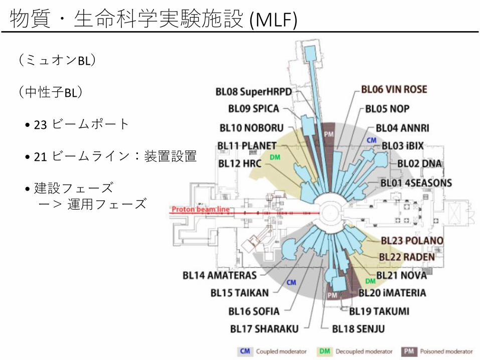
物質・生命科学実験施設 (MLF)
(ミュオンBL)
(中性子BL)
• 23 ビームポート
• 21 ビームライン:装置設置
•建設フェーズー>運用フェーズ

Optical fiber
35
cm
Effective area: 128 x 128 mm2
35 cm
BL17
BL03
BL19
1-d large areascintillator detector
MLFビームラインにて稼働中の中性子検出器
He-3 PSD
2-d large area scintillator detectorusing WLSF
2-d compactscintillator detectorusing WLSF
BL18
BL01, BL02, BL08, BL09, BL11, BL12BL14, BL15, BL16, BL17, BL20, BL21
MWPC
●汎用ヘリウム3ガス検出器
BL16, BL17RPMT
Multi-wire proportional counter
●ガス型 2次元検出器(基盤S 藤)
●シンチレータ型1・2次元検出器(基盤S 中村(龍))
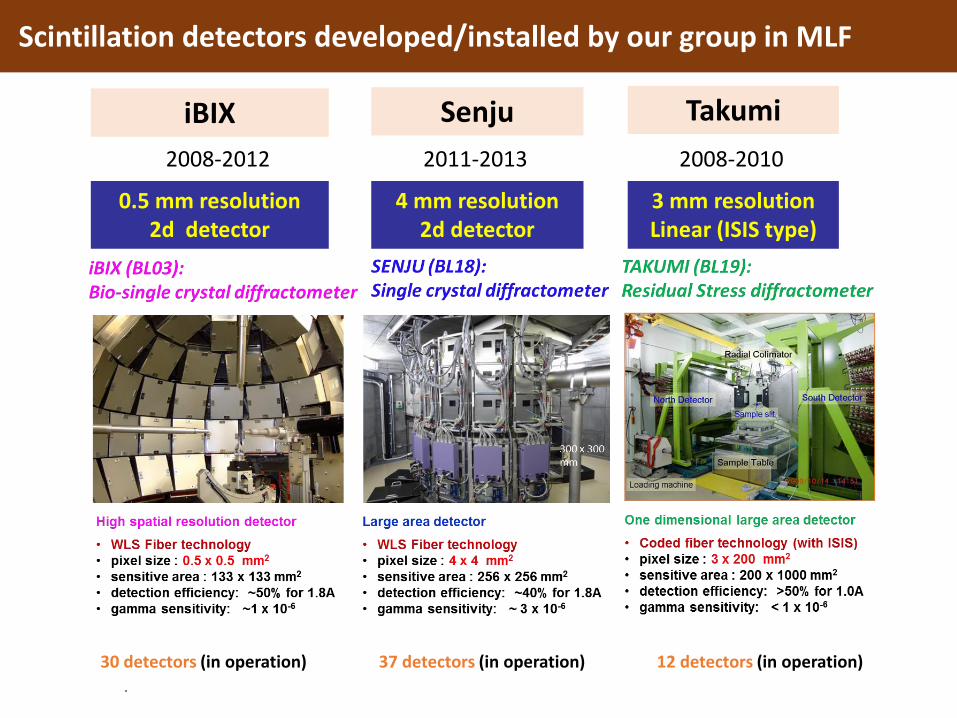
Scintillation detectors developed/installed by our group in MLF
iBIX
4 mm resolution2d detector
Senju
3 mm resolutionLinear (ISIS type)
0.5 mm resolution2d detector
Takumi
2008-2012 2011-2013 2008-2010
30 detectors (in operation) 37 detectors (in operation) 12 detectors (in operation)
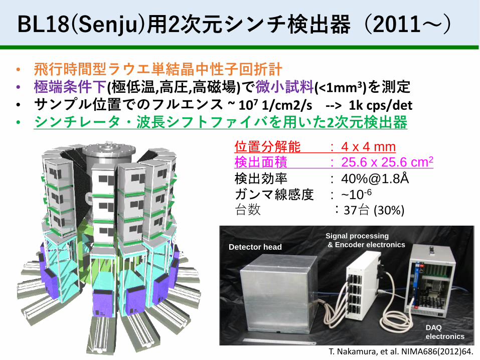
BL18(Senju)用2次元シンチ検出器(2011~)
• 飛行時間型ラウエ単結晶中性子回折計• 極端条件下(極低温,高圧,高磁場)で微小試料(<1mm3)を測定• サンプル位置でのフルエンス ~ 107 1/cm2/s --> 1k cps/det• シンチレータ・波長シフトファイバを用いた2次元検出器
位置分解能 : 4 x 4 mm検出面積 : 25.6 x 25.6 cm2
検出効率 : 40%@1.8Å
ガンマ線感度 : ~10-6
台数 :37台 (30%)
Detector head
Signal processing
& Encoder electronics
DAQ
electronics
T. Nakamura, et al. NIMA686(2012)64.
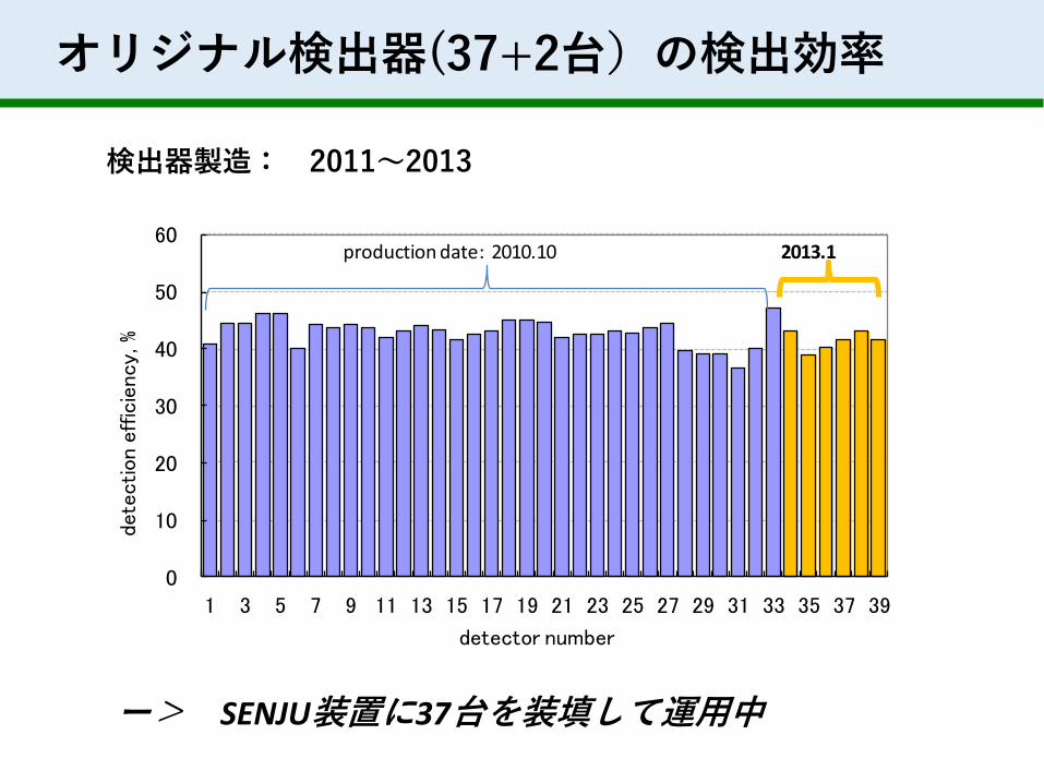
オリジナル検出器(37+2台)の検出効率
0
10
20
30
40
50
60
1 3 5 7 9 11 13 15 17 19 21 23 25 27 29 31 33 35 37 39
dete
ctio
n ef
ficie
ncy,
%
detector number
production date: 2010.10 2013.1
ー> SENJU装置に37台を装填して運用中
検出器製造: 2011~2013
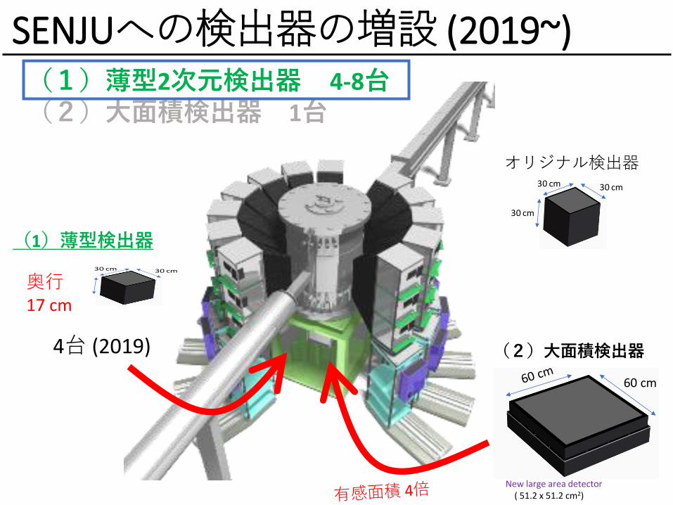
SENJUへの検出器の増設 (2019~)(1)薄型2次元検出器 4-8台(2)大面積検出器 1台
30 cm30 cm
30 cm
60 cm
New large area detector ( 51.2 x 51.2 cm2)
(2)大面積検出器
(1)薄型検出器
30 cm30 cm
30 cm奥行17 cm
オリジナル検出器
4台 (2019)

シンチレータ・WLSF検出器のヘッド構造
(ポイント) ピクセルサイズ、大カバレージ、検出効率、低コスト
① WLSファイバを4mmピッチで配置 →低コスト、大面積化② 2枚のシンチレータスクリーンを配置→検出効率③クリアファイバ接続・後方ベンド →不感領域の低減
Scintillator (front)
①WLS
fibers
③ Clear fibers
neutron
②ZnS/10B2O3
scintillatorsKey Designs
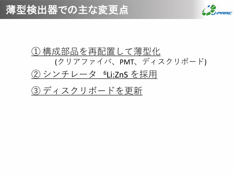
①構成部品を再配置して薄型化(クリアファイバ、PMT、ディスクリボード)
②シンチレータ 6Li:ZnS を採用
③ディスクリボードを更新
薄型検出器での主な変更点
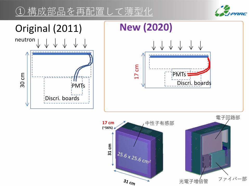
①構成部品を再配置して薄型化
17 cm(~56%)
31
cm
光電子増倍管
電子回路部
ファイバー部
中性子有感部
Original (2011)
Discri. boards
PMTs30
cm
neutron
Discri. boards
PMTs
17
cm
New (2020)
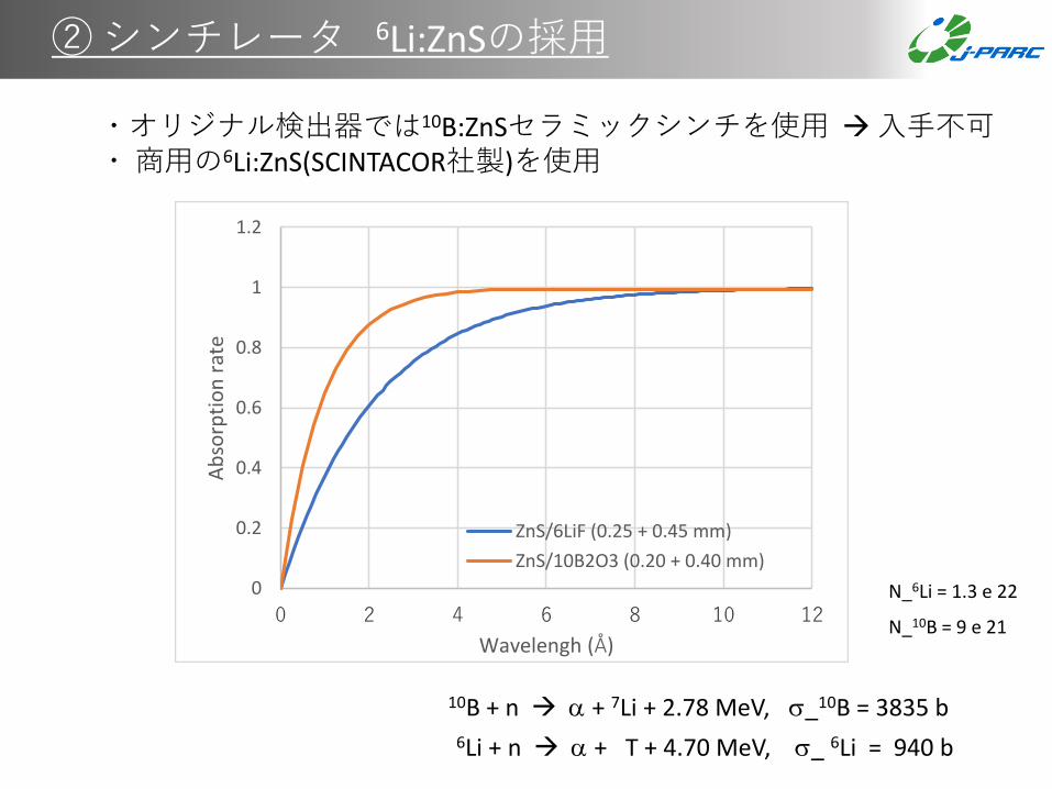
②シンチレータ 6Li:ZnSの採用
0
0.2
0.4
0.6
0.8
1
1.2
0 2 4 6 8 10 12
Ab
sorp
tio
n r
ate
Wavelengh (Å)
ZnS/6LiF (0.25 + 0.45 mm)
ZnS/10B2O3 (0.20 + 0.40 mm)
10B + n → a + 7Li + 2.78 MeV, s_10B = 3835 b6Li + n → a + T + 4.70 MeV, s_ 6Li = 940 b
・オリジナル検出器では10B:ZnSセラミックシンチを使用 →入手不可・商用の6Li:ZnS(SCINTACOR社製)を使用
N_6Li = 1.3 e 22
N_10B = 9 e 21
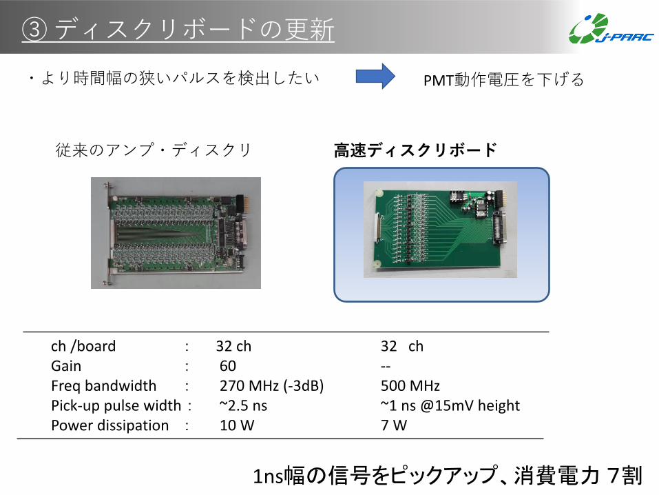
③ディスクリボードの更新
PMT動作電圧を下げる
従来のアンプ・ディスクリ
ch /board : 32 ch 32 chGain : 60 --Freq bandwidth : 270 MHz (-3dB) 500 MHzPick-up pulse width : ~2.5 ns ~1 ns @15mV heightPower dissipation : 10 W 7 W
1ns幅の信号をピックアップ、消費電力7割
高速ディスクリボード
・より時間幅の狭いパルスを検出したい
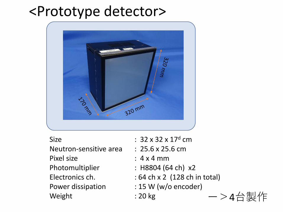
Size : 32 x 32 x 17d cmNeutron-sensitive area : 25.6 x 25.6 cmPixel size : 4 x 4 mm Photomultiplier : H8804 (64 ch) x2Electronics ch. : 64 ch x 2 (128 ch in total)Power dissipation : 15 W (w/o encoder)Weight : 20 kg
<Prototype detector>
ー>4台製作

0
2000
4000
6000
8000
10000
12000
14000
16000
18000
20000
700 750 800 850 900 950 1000
Co
un
t (a
.u.)
PMT voltage (V, negative)
TAP50, discri., 6TAP50, discri., 8BA50, discri., 6BA50, discri., 8
New card
Original card
new cards
~80V
■ Plateau characteristics
PMT gain2e6 3e61e66e5
Maximum rating ofMaPMT (H8804)
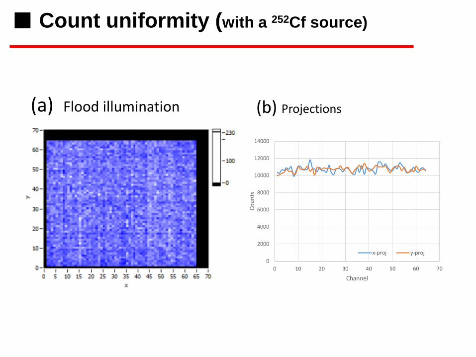
252Cf線源での測定
0
2000
4000
6000
8000
10000
12000
14000
0 10 20 30 40 50 60 70
Co
un
ts
Channel
x-proj y-proj
(a) Flood illumination (b) Projections
■ Count uniformity (with a 252Cf source)
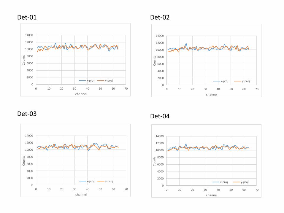
Det-01 Det-02
Det-03 Det-04
0
2000
4000
6000
8000
10000
12000
14000
0 10 20 30 40 50 60 70
Co
un
ts
channel
(4) uniformity (din50cm, 400s)
x-proj y-proj
0
2000
4000
6000
8000
10000
12000
14000
0 10 20 30 40 50 60 70
Co
un
ts
channel
(7) uniformity (din50cm, 400s)
x-proj y-proj
0
2000
4000
6000
8000
10000
12000
14000
0 10 20 30 40 50 60 70
Co
un
ts
channel
(7) uniformity (din50cm, 400s)
x-proj y-proj
0
2000
4000
6000
8000
10000
12000
14000
0 10 20 30 40 50 60 70
Co
un
ts
channel
(7) uniformity (din50cm, 400s)
x-proj y-proj
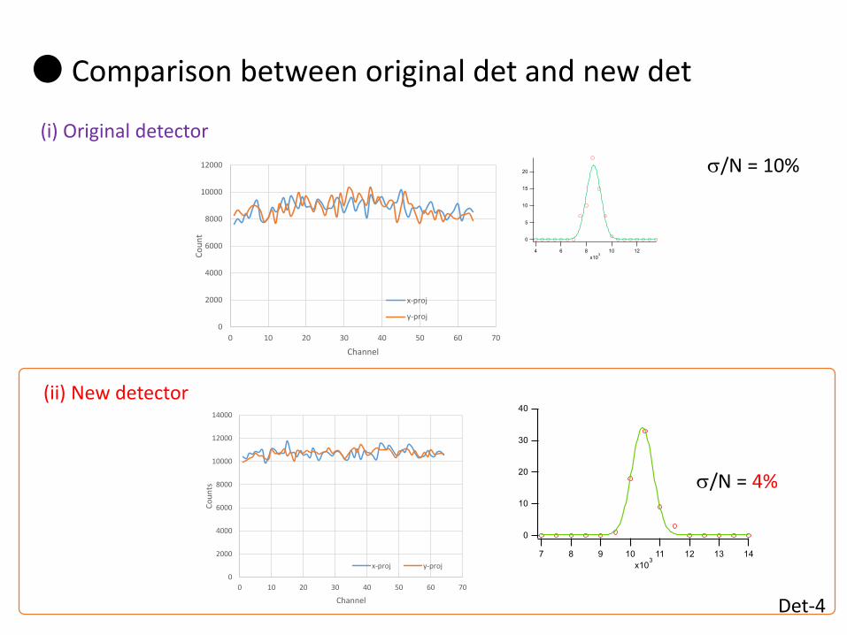
s/N = 10%
s/N = 4%
Det-4
● Comparison between original det and new det
(ii) New detector
(i) Original detector
0
2000
4000
6000
8000
10000
12000
14000
0 10 20 30 40 50 60 70
Co
un
ts
Channel
x-proj y-proj
0
2000
4000
6000
8000
10000
12000
0 10 20 30 40 50 60 70
Co
un
t
Channel
x-proj
y-proj
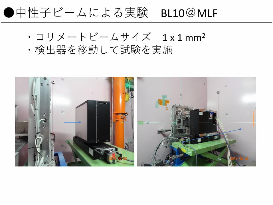
・コリメートビームサイズ 1 x 1 mm2
・検出器を移動して試験を実施
●中性子ビームによる実験 BL10@MLF

y = 0.9946x + 1.0594R² = 0.9998
020406080
100120140160180200220240260
0 20 40 60 80 100 120 140 160 180 200 220 240 260
Mea
sure
d p
osi
tio
n (m
m)
Beam position (mm)
Measured positionmeasuredposition
y = 0.9937x + 1.147R² = 0.9998
020406080
100120140160180200220240260
0 20 40 60 80 100 120 140 160 180 200 220 240 260
Mea
sure
d p
osi
tio
n (m
m)
Beam position (mm)
Measured position measuredposition
(x方向) (y方向)
■ Position linearity
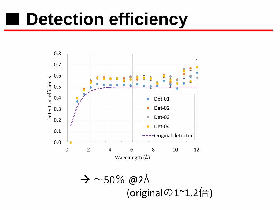
→~50% @2Å
■ Detection efficiency
0.0
0.1
0.2
0.3
0.4
0.5
0.6
0.7
0.8
0 2 4 6 8 10 12
Det
ecti
on
eff
icie
ncy
Wavelength (Å)
Det-01
Det-02
Det-03
Det-04
Original detector
(originalの1~1.2倍)
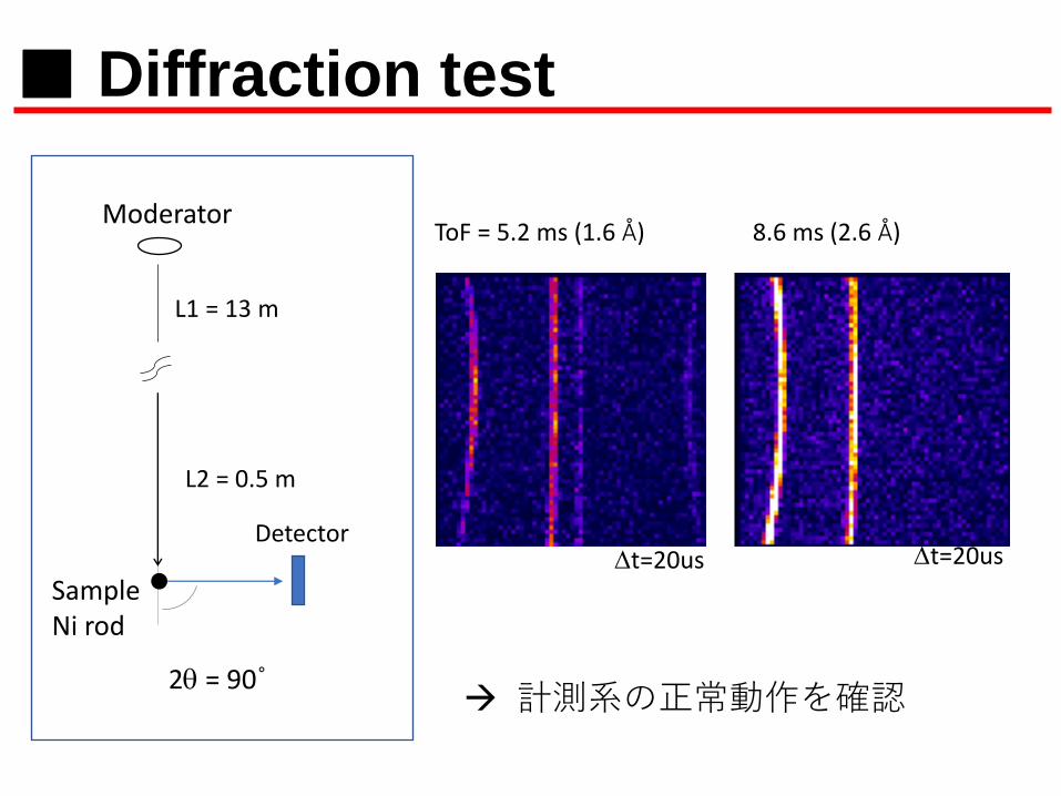
ToF = 5.2 ms (1.6 Å) 8.6 ms (2.6 Å)
■ Diffraction test
→ 計測系の正常動作を確認
Moderator
Detector
SampleNi rod
L1 = 13 m
L2 = 0.5 m
2q = 90˚
Dt=20us Dt=20us
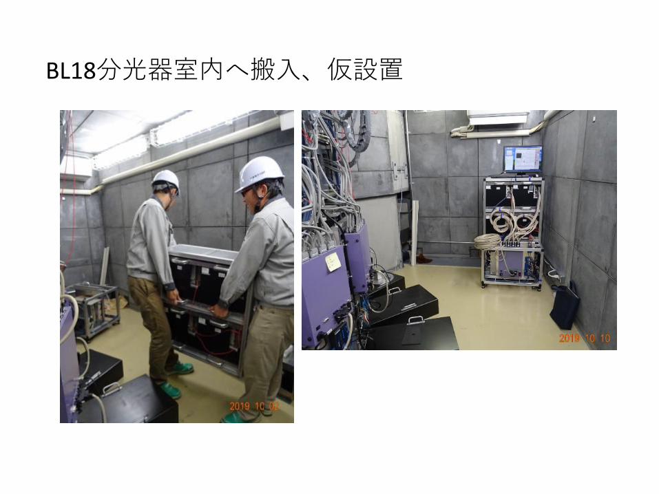
BL18分光器室内へ搬入、仮設置
0
0.02
0.04
0.06
0.08
0.1
0.12
0.14
0.16
0 1 2 3 4 5 6 7 8 9 10
cou
nt
(1/s
/det
)
days
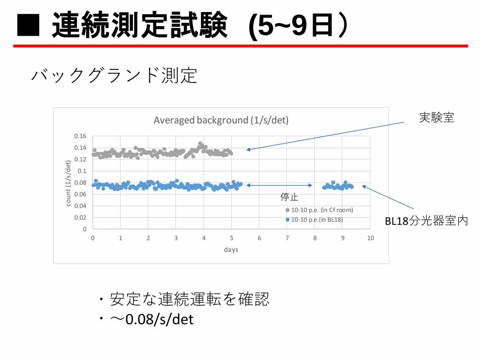
Averaged background (1/s/det)
10-10 p.e. (in Cf room)
10-10 p.e.(in BL18)
バックグランド測定
・安定な連続運転を確認・~0.08/s/det
実験室
BL18分光器室内
■連続測定試験 (5~9日)
停止
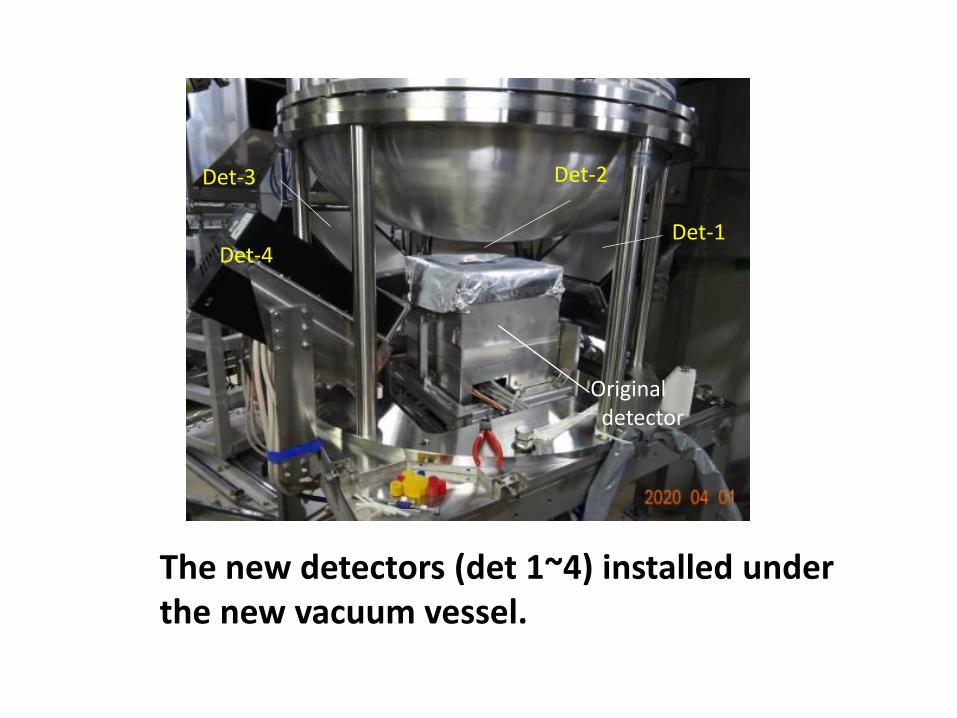
The new detectors (det 1~4) installed under the new vacuum vessel.
Det-1
Det-2Det-3
Det-4
Original detector
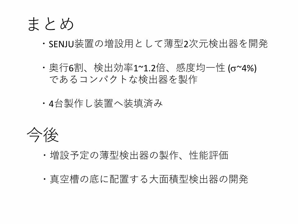
まとめ・SENJU装置の増設用として薄型2次元検出器を開発
・奥行6割、検出効率1~1.2倍、感度均一性 (s~4%)であるコンパクトな検出器を製作
・4台製作し装置へ装填済み
今後・増設予定の薄型検出器の製作、性能評価
・真空槽の底に配置する大面積型検出器の開発