Embed Size (px)
Citation preview

BED BLENDING OF FOSSIL FUELS
by
FRANK J. LOEFFLER, P.E. Regional Manager Robins Engineers & Constructors
GREGORY A. VAKA Regional Manager Robins Engineers & Constructors Whittier, California 90605
This paper discusses how bed blending systems can be applied to the utilization of fossil fuels. The subjects of quality control and available stacking and reclaiming equipment are also explored along with a case history of bed blending at Utah International Corporation's Navajo Mine.
INTRODUCTION
It will be the purpose of this paper to discuss how bed blending systems can be applied to the utilization of fossil fuels_ The paper will also deal with locations for blending systems, types of storage piles. equipment. quality control, and a case history of a bed blending application. Since the available technical material on blending is extensive, it is suggested the reader consult the bibliography at the end of this report for further information.
WHY AND WHERE TO BLEND
Four primary bed blending locations should be considered: at the mine. at the coal preparation plant, at the transshipment facility, and as part of the user's coal handling system whether it be for combustion or the conversion to synthetic fuels.
Blending at the mine is employed to increase the available mine reserves by utilizing crop coal and to reduce the need for selective mining techniques_ This is accomplished by utilizing coal or lignite that contains unacceptable properties and blending them into the desired mixture. One example of a complete coal blending system located between a strip mine and a power plant can be found at the Navajo Mine located near Arizona Public Service Company's Four Corners Power Plant in New Mexico. We will discuss this installation in detail in this report.
1
Transshipment facilities can economically utilize bed blending if their fuel contracts involve specific grading limitations on Btu, sulfur, and/or ash. Blending will enable them to produce a lower cost fuel by custom blending to specific specifications the coal or lignite received from various sources. When more than one mode of transportation is used to transship the coal, the offloading and reloading at the ship or rail terminal offers an excellent opportunity for blending the varying grade of coals. The blending of different coals can be accomplished without any additional major expense since a coal handling system would already be a necessity.
Equally if not more important would be the blending of raw coals from different mines or from different locations within the same mine just prior to their beneficiation. The cost of coal beneficiation has been shown to decrease markedly with increased production_ Substantial benefits could be derived if the output from two or more mines was combined to provide a cornmon feedstock to a single beneficiation plant. In considering the use of blending prior to the beneficiation process, careful attention must be paid to the washability characteristics of each coal source and to make certain that the finished blend has acceptable Btu, sulfur, and/or ash properties.
At the power plant upgrading the fuel by bed blending could result in a lower capital expenditure in boilers and auxiliary equipment since a wide latitude boiler is not required. Normally the boiler and its auxiliary equipment must be designed to accomodate the volume of the lowest Btu fuel anticipated. If the blended fuel is of a higher BTu value, the boiler can be sized smaller and thus cost less.
There is also evidence that boiler slaging could be considerably lessened by

uniform Btu coal. One reason for slagging is thought to be the anomalouS upward fluctuations in heat value of the incoming fuel. These flucuations cause the fire to burn higher and hotter in the box thus inducing slagging conditions. Uniform quality fuel could eliminate this major cause of slagg-
ing. Ash removal problems associated with the furnace and the precipitators can be reduced if the variation of ash content is kept within practical limits. Short term variations of ash content may result in "slugging" of the precipitators with larger than normal amounts of ash. This could cause a grounding of the electrostatic precipitation field, violation of antipollution laws, and possible large fines. As with the precipitators, furnishing uniform quality coal would eliminate high ash surges, thereby reducing the size and complexity of the bottom ash handling equipment.
perhaps the most important of all blending applications would be the utilization of western sub-bituminous coals for boilers that would otherwise be unable to fire them efficiently. AlsO by upgrading the fuel, blending would reduce the cost of flue gas de sulfurization (FGD) systems.
In a synthetic fuel facility, bed blend-
value, volatile matter, and aggJ~omerating properties as defined in the ASTM Standard D-388, "specification for the Classification
of Coals by Rank" ~
Bed Blending Bed blending is a term applied to a bulk
materials system handling large qualities of nonuniform materials and turning them into an acceptable homogenious plant feed. This is accomplished by spreading the raw materials at a constant uniform rate, back and forth over a long rectangular area and gradually building up a bed of several hundred layers of material in triangular cross sections~ Reclaiming of the layered bed is performed by consecutively removing small crosS sections. Each slice of the crosS section to be removed will then have the same physical and chemical properties as the entire bed.
Returning to our discussion of blending, we wish now to explain how a bed blending storage pile is formed.
ing can result in a more uniform particle size of the feedstock. This would minimize the size of the screening station necessary to segregate the various constituent sizes prior to the feeding of the gasifier. A more efficient gasifier operation would result if the feedstock could be held within a Btu value of not more than 250 Btu's from its average value.
Both power and conversion plants usually require extensive dead stora~2 piles for emergency use as well as the live storage capacity needed to satisfy the plant's fuel requirements between shipments. The coal stockpiling and reclaiming facilities generally represent a substantial investment, both in capital and in acreage. The incremental cost of providing bed blending to these facilities is quite reasonable and worthy of serious consideration.
To be successful, blending requires a judicious selection of coals. Random selection of coals for blending can cause deterioration of the ash characteristics \vi th the possibility of further combustion problems due to a lowered ash fusion temperature.
DEFINn'IONS
Before getting into the details of the bed blending systems and their economics, it would be wise to set the definition of terms
we will be using.
coal Rank While steam generating units have been
Fig. 1 Single Boom Travelling Stacker
fired successfUlly using all ranks of coal from anthracite to lignite. auxiliary equipment design will vary according to the chemical and physical properties of fuel, as well as those properties defined in estab-lishing rank. Rank classifications are based on varying combinations of moisture, heating Fig. 2 Double Boom Travelling stacker
2

HOW A STORAGE PILE IS FORMED
Stockpiling of materials in layered beds can be accomplished in a number of ways.
1. A single, slewing or fixed, boom travelling stacker, Fig. 1.
2. A double boom travelling stacker, Fig. 2
3. Overhead tripper, Fig. 3. 4. Radial stacker with telescopic
head, Fig. 4. 5. Circular storage stacker.
These stackers are generally equipped with luffing boom conveyors to minimize the drop of material to the pile after discharge. For automatic stockpiling the boom tip is equipped with "a level detector (S) which can be electrically interlocked with the hoists. The timing relay in this circuit permits the boom to be raised automatically in increments as the pile is progressively b~ilt up. For materials which must be blended under shelter or which are not subject to segregation the travelling tripper in the apex of the building roof is frequently employed.
Fig. 3 Seal Belt Tripper
Fig. 4 Radial Stacker with Telescopic Head
LAYERING METHODS
Blending beds can be built up using any ~f a number of layering methods.
3
Chevron Method, Fia. 5 This bed blending method is the most
commonly employed since it has the following advantages.
I. It is possible to add an additive or corrective material at anytime, even during the last few passes of the stacker, over the entire pile length to obtain the required blend.
2. Partial blending of the bed end cones is simpler.
3. The stacker can be a non-slewing type with a boom of minimum length (since it must only extend to the pile center). Result is a lower stacker weight and a lower overall installed cost.
4. Automation of the stacker movement is comparatively simple.
The disadvantage of the chevron method is greater particle segregation in the bed cross section. The significance of this phenomenon will be discussed later. If segregation is of major importance and results in unacceptable variations in the recovery of the blend, other stacking methods can be employed.
Fig. 5 Chevron Pile Cross Section
Fig. 6 Windrow Pile Cross Section
Windrow Method, Fig. 6 Using this blending method, the bed is
composed of numerous small layered beds. Particle segregation is considerably reduced and distributed throughout the cross section. The disadvantages of this method are:
J.. If blend corrections must be made at random, they will only be in certain parts of the bed cross section.
2. A slewing stacker with a long boom (boom discharge must extend to outer row) is required resulting in a higher cost unit than for the chevron method discussed above.
3. By building the individual small beds the stacker has to operate between many reversing point~ at the pile ends.
4. Blending of the bed end cones is difficult to accomplish, possibly making it necessary to recirculate portions of the end cones.

5. Automation of stacker movement is complex requiring computer control.
Modified Windrow or Six Row Method. Fig. 7 This is a compromise between the chevron
and windrow methods. The bed is built up by depositing three small layered beds to form the base of the pile and then filling in these layered piles to complete the full bed cross section. With the modified windrow method, particle segregation is somewhat reduced and distributed within the pile cross section as compared to the chevron method.
The disadvantages of this system are similar to those of the windrow method but on a reduced scale. Automation of the stacker movement is still complex and often semiautomatic operation is adapted. For this operation the plant operator first sets the boom location to commence the forming of each of small individually layered beds and he then puts the machine in the automatic mode.
Fig. 7 Modified Windrow Pile Cross Section
Circular ~.!les The formation of a circular pile can be
accomplished by eit.her the chevron or windrow method of layering.
Th(= chevron method requires the use of d simple luffing boom radial stacker. However. the pile that is to be formed in a windrow fashion requires the use of a portal frame supporting a conveyor with tripper or a shuttle conveyor system to reach to the near and fnr sides of the pile.
Fig. 8 Circular Storage System
The stacker rotates around a column fixed in the center of the circular storage pile. The central column not only supports the stacker but also supports the rotary reclaimer, the incoming conveyor supplying material to the stacker, and", if the pile is to be enclosed, it can also be used to
support the roof. (See Fig. 8) The blending of materials can be accom
plished by a number of methods.
l. 2. 3.
Separate batches. Batch on batch. continuous batch.
In cases 1. and 2. above. both chevron and windrow stacking can be employed. In case 3., only chevron stacking is used.
separate Batches. Here two working pi~es ~re used. Each pile occupies less than one i,alf of the entire circular area. The piles are separated by a permanent dead pile. 'rhe permanent dead pile is there to eliminate end cone formation. Material is layered agalDst the sloping surface of the dead pile and is reclaimed up to this pile.
Separate batch piles can be layered in either chevron or windrow patterns. If the chevron method is employed, a luffing boom stacker can be used. By lowering the boom to a point just above the top of the formed pile. a minimum freefall height is allovled. thus keeping dusting to a minimum.
In windrow piling, a shuttle conveyor or a conveyor with tripper system must be emplo,,::"ed. In both chevron and windrow stacking, the free fall of material from a point above the highest point of the pile to the floor elevatio:J. can create an undesirable amount of dust. In some cases, the use of dust collection equipment is reauireo-
When 6uilding a windrow plle in a circular ~;torage area, one of three methods must be llsed to assure that the volume of material deposited into each wi.ndrow is uniform due to the differ ent radii on which each windrow is constructec . ..&...
As the radius of the windrow being constructed increases, either the speed of the stacker rotation is decreased, the number of passes over onc point is increased, or the input capacity to the stacker is increased.
with both windrow nnd chevron batch stacking, a permanent dead pile is required to separate the piles. This dead area occupies space that would othervlise be used for live storage.
4
A reversible reclaimer is used in conjunction with the separate batch storage system. ~'Ij"hile one pile is being reclaimed, the other pile is being bedded_
i\dditional control equipment is required for a windrow formed pile compared to a chevron formed pile.
Batch on Batch. In this case, the initial pile constructed is generally two thirds of the total storage area. The storage pile can be either of windrow or chevron construction.
When the initial pile is ready for reclaim and the reclaimer is set into operation. the stacker is moved to begin forming a new pile that places the second batch in the remaining one-third area.
In the case of a chevron constructed pile. the stacker builds the second batch against the end cone of the first batch hence "batch on batch" pile construction.
Pile formation, as in separate batching. ~--

can be through the use of a luffing boom stacker to minimize dusting. At the end of construction of the second pile, the two piles appear to be one, seamless and uniform. However, it must be noted that the material layered in the end cone of the first pile and the overlapping end section of the second pile will not have the uniform blend of a continuous pile. There will be some difference in the blend of materials within the end cone section when compared to other sections of the pile.
During construction of the second pile. the blended material is being reclaimed in a continuous clockwise fashion. leaving room for the third pile to be constructed in the same way as the second.
Windrow piling can also be used in batch on batch stacking through the use of the same type of machinery described under the separate batch system except for one additional complication. Since the initial pile construction is two thirds of the entire area and the second and all following piles will be of either one third or some other portion of the entire area, adjustable end-of-travel stops for the stacking machinery must be employed.
Unlike the separate batch system, there is no down time in the reclaim cycle of the batch on batch system due to repositioning of the reclaimer.
The reclaimer operation is continuous with only the stacker operating limits requiring periodic adjustment for relocation of the stacker.
Continuous Batch. The continuous batch method is one developed recently for a storage/reclaim system that Robins Engineers and Constructors is providing in the United States.
The continuous batch system is unique in that the stacking and reclaim operation is continuous. Repositioning of equipment is never necessary.
The heart of this new concept is the method in which the pile is built. Rather than building horizontal layers in either a chevron or windrow pattern, the pile is constructed in an inclined chevron pattern. This results in a multi-layered pile with a vertical apex that slopes downward to grade terminating in a horizontal point. (See Fig. 9)
'rhe initial pile is constructed of the proper arc length and with a sloping surface to layer the incoming material on a predetermined angle. The length of the tapering pile is calculated based on the blending efficiency desired and the properties of the incoming material.
The blending pile is then constructed by slewing the stacker between limits over the top of the inclined portion of the initial pile. As the stacker rotates from one end of the pile to the other. the luffing mechanism keeps the top of the boom just above the top of the formed pile to keep free fall and dusting to an absolute minimum.
On each successive back and forth pass, an additional layer is added to the inclined or "tail" section of the pile. When the
5
level of material at the high end reaches the prescribed pile height, the boom then automatically indexes a short distance in the direction of pile construction (towards the low end) which also advances the position of the tip of the pile tail. The boom then indexes between these limits adding inclined chevron layers to the pile.
D,e!Oq,e',, ___ of,
_8J-''''~'
/ Ll\-: :::';;;;_~I
!'-"_~_~"'-_ -<:C-
i
/ /
/
, /' .. ~~~ /'
/
f-.. i 8LF .. OE", P'~£ s.-C' .. ,~ .... -r' T"" -,
Fig. 9 Circular Pile Cross Section
Each time the level of material reaches the prescribed high level, the stacker boom indexes to new limits continuing to build layers until it has rotated back to the initial starting point just behind the reclaimer.
As the reclaimer advances, drawing blended material from the pile, the stacker continues to place material into storage following the reclaimer making full utilization of the area available.
Since the continuous batch method uses inclined chevron layering to form the pile, it is not necessary to be concerned with changing the boom rotation speed, number of passes, or input capacity to control incoming volume as explained earlier for windrow pile construction of a radially formed pile.
The circular chevron built stockpile has the same advantage over the linear pile. The thickness of layers in a linear system vary due to the relative speed difference between the stacker travelling with or against the direction of material flow, causing varying volumes of material to be delivered to the pile. With the circular yard, the material is supplied to the center and no relative speeds exist.
RECLAIMING METHODS
Messiter Reclaimer, Fig. 10 The harrow (rake) of this machine covers
the entire bed base and has an independent horizontal movement. The many projecting teeth on its forward face disturb the material particles in the entire bed cross section. Particles cascade down the forward face to the bed base. The Messiter reclaimer moves continually forward into the bed and capacity is regulated by this forward speed. A plow
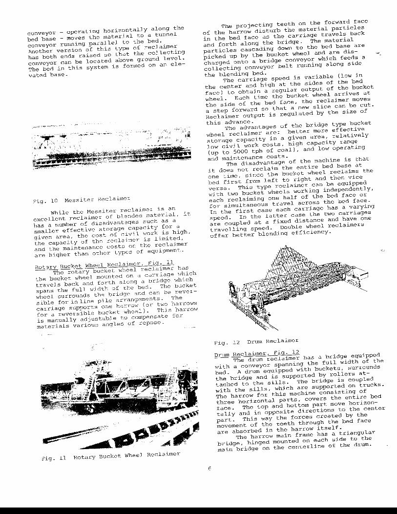
conveyor _ operating horizontally along the bed base - moves the material to a tunnel conveyor running parallel to the bed. .~other version of this type of reclaimer has both ends raised so that the collecting conveyor can be located above ground level. The bed in this system is formed on an ele-
vated base.
Fig. 10 Messiter Reclaimer
While the Messiter reclaimer is an excellent reclaimer of blended material, it has a number of disadvantages such as a smaller effective storage capacity for a given area, the cost of civil work is high, the capacity of thR reclaimer is limited, and the maintenance costs on the reclaimer are higher than other types of equipment.
Rotary Bucket Wheel Reclaimcr, FlQ. 11 The rotary bucket wheel reclaimer has
the bucket wheel mounted on a ca;:-riage which travels back and forth along a bridge which spans the full width of the bed. The bucket wheel surrounds the bridge nnd can be reversible for in line pile arrangements. The carriago supports one harrow (or two harrows for a reversible bucket wheel). This harrow is manually adjustable to compensate for materials various angles of repose.
.~~'<:£A'~ ~~ ,;',: .'
Fig. 11 Rotary Bucket Wheel Reclaimer
The projecting teeth on the forward face of the harrow disturb the material particles in the bed face as the carriage travels back and forth along the bridge. The material particles cascading down to the bed base are picked up by the bucket wheel and are discharged onto a bridge conveyor which feeds a collecting conveyor belt running along side the blending bed.
The carriage speed is variable (low in the center and high at the sides of the bed face) to obtain a regular output of the bucket wheel. Each time the bucket wheel arrives at the side of the bed face, the reclaimer moves a step forward so that a new slice can be cut_ Reclaimer output is regulated by the size of this advance.
The advantages of the bridge type bucket wheel reclaimer are: better more effective storage capacity in a given area, relatively low civil work costs, high capacity range (up to 5000 tph of coal), and low operating and maintenance costs.
The disadvantage of the machine is that it does not reclaim the entire bed base at one time, since the bucket wheel reclaims the bed first from left to right and then vice versa. This type reclaimer can be equipped with two bucket wheels working independently, each reclaiming one half of the bed face or for simultaneous travel across the bed face. In the first case each carriage has a varying speed_ In the latter case the two carriages are coupled at a fixed distance and have one travelling speed. Double wheel reclaimers offer better blending efficiency.
Fig. 12 Drwn Reclaimer
Drum Reclaimer, Fig. 12 The drum reclaimer has a bridge equipped
with a conveyor spanning the full width of the bed. A drum equipped with buckets, surrounds the bridge and is supported by rollers attached to the sills_ The bridge is coupled with the sills, which are supported on truckS. The harrow for this machine consisting of three horizontal parts, covers the entire bed face. The top and bottom part move horizontally and in opposite directions to the center part. This way the forces created by the movement of the teeth through the bed face are absorbed in the harrow itself_
The harrO\'l main frame has a triangular bridge, hinged mounted on each side to the main bridge on the centerline of the drum.

It is supported with adjustable members on the sills. with this arrangement. the position of the bottom row of teeth in the harrow maintains a fixed distance to the bucket lip circle at any position of the harrow. The drum reclaimer continuously advances into the bed which can be regulated to meet capacity requirements. The drum reclaimer can also be equipped with reversible buckets and two harrows for in line pile configurations.
This drum reclaimer. as with the rotary bucket wheel, overcomes the disadvantages of the Messiter reclaimer and also permits reclaiming the entire bed face at one time.
The disadvantage of the drum reclairner is basically one of weight and the heavy construction required to support the drum. resulting in higher initial cost. End cone recirculation time is longer. reducing the bed efficiency and requiring larger plant bunkers.
, ',-u"'2'-r?
~~~~~~
, \ \ .... "
Fig. 13 Rotary Scraper Reclaimer
Rotary Scraper Reclaimer The rotary scraper reclaimer consists
of a bridge supported chain scraper and harrow that rotates through 360°, reclaiming stored material to the center of the storage pile where it is transferred through a central hopper to an underground receiving conveyor.
The circular scraper reclaimer operates fully automatically. The reclaimer is supported on one end by rail mounted trucks. The other end is supported by a bearing located on the central support column that is also used to support the stacker, incoming conveyor supplying material to the stacker, and building roof structure.
7
The reclaimer advances towards the pi 1 €
driven by the wheeled trucks on the outside circular rail. The rate of speed that the rec~aimer advances into the pile is adjustable and controls the rate of tonnage reclaimed.
Fig. 14 Rotary Scraper Reclaimer in Storage Dome
A harrow is mounted on the reclaimer bridge and moves back and forth against the face of the pile. The projecting teeth on the harrow contact the bedded material with positive force, loosening the particles and causing them to flow to the base of the pile. At the base of the pile, the material forms a Vlave that is a homogenous blend of the vertical cross section.
The horizontal scraper chain that is suspended beneath the bridge beam is then used to blend each foot of vertically blended material across the face of the pile. Theoretically. every blade on the scraper chain reclaims a little portion from each foot of the pile width. Each scraper gaining volume as it passes across the entire width of the pile until a complete cross sectional composition of the pile is obtained. (See Fig. 13 & 14)
There are basically two types of face raking devices. The wire rope device and the rigid harrow. The wire rope devise acts much like a windshield wiper. sweeping over the whole pile face. Generally, there are two ropes used that are hinged at the upper apex of the bedding pile. At the lower end, they are mounted on a carriage that moves along the pile base. The rope lies loosely on the pile face and cuts off a slice of the storage pile. Generally, the rope devise is considered best suited for small, grain size materials. The harrow, with its many projecting teeth and rigid heavy const~uction. is better suited for the larger particle size or higher tonnage capacity applications.
Boom Type Stacker Reclaimer. Fig. 15 This is an adaptation of the conventional
bucket wheel reclaimer design. A harrow, provided at the end of a boom, agitates the face of the pile as the machine advances down from the center of the pile. The boom swings in an arc from 'side to side. Reclaim capacity for this machine is subject to surges and accurate blending is not possible due to the arcual movement of the harrow. However, for systems not requiring extreme accuracy but requiring

a high tonnage output, this boom type reclaimer is worthy of consideration.
Fig. 15 Boom Type Stacker Reclaimer
Rotary Plow Feeders, Fig. 16 These tunnel machines are mentioned here
because they do have a limited application in bed blending systems. Rotary plow feeders are generally installed in long tunnels under a slot bunker having a 'v' shaped bottom cross section. (See Fig. 17) A tunnel is provided with two or more plows which rotate in a horizontal plane reclaiming the material from one or two shelves. The rotary plows slowly traverse back and forth discharging material onto a conveyor at the bottom of the tunnel. This system lends itself to blending two basic fuels such as high and low sulfur content coals. One travelling plow feeder would be operating under each pile of the different coal ranks. The collecting conveyor, receiving the material in two layers, would carry the mixture which would be blended by the tumbling action of subsequent transfers. In this sense, the system is somewhat like bin blending system.
Fig. 16 Rotary plow Feeder
The advantage of bunker s~orage is the relatively lower cost as compared with above ground bins when large quantities have to be stored. The efficiency of blending with this
system.is less than the other systems previously discussed and is not recommended when more than two materials have to be combined.
8
',::
,. "'tI( i ,--
~~
Fig. 17 Rotary plow Feeder Tunnel
Although the terms blending and mixing are used interchangeably, this does not imply that the two terms are synonymous - but rather that in many instances a conventional mixing action will be entirely satisfactory. This is especially true when the purpose of mixing is primarily an averaging procedure, such as the mixing of coals having different sulfur contents prior to combustion.
BLENDING QUALITY CONTROL
Removing material continuously in small uniform transverse increments by a reclaim machine has the same effect as continuously sampling the entire contents of the storage pile. Interval spacing and number of sample cuts correspond to the pile length and the number of layers. Since each sample is representative of the whole, each layer represents an exact portion of the whole and each transverse cut must therefore be a true representation of the average of the entire pile. It follows that the sum of the transverse cuts, which is the total pile recovery, will be uniform in both chemical and physical analysis.
The most convenient method to measure uniformity is standard deviation. A mathematical formula can be applied to the analysis of each component making up the entire lot. It is the square root of the average of the squares of the individual deviations of all samples from their mean.
D2 m
a)2 !. =L. (Xv .
vl m
where D Standard Deviation
m Number of samples
Xv Individual deviation of any desired property
a Average property m !. and a =LX . vl v m
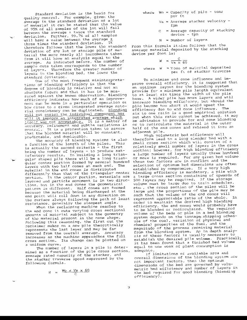
Standard deviation is the basis for quality control. For example, given the average in the standard deviation of a lot of material it can be stated that the value of 95% of all samples of the lot will fall between the average ± twice the standard deviation. Further, 99.7% of all samples will have a value between the average ± three times the standard deviation. It therefore follows that the lower the standard deviation of any lot or storage pile of material the morc nearly all increments taken from it will have an analysis equal to the average. As indicated before, the number of sample cuts taken corresponds to the number of layers. Therefore the greater number of layers in the blending bed, the lower the standard deviation.
One of the most frequent misinterpretations of blending efficiency is that the degree of blending is relative and not an absolute figure and that it has to be measured against the known observation. Blending efficiency indicates how much of an improvement can be made in a particular operation or how close to a given integrated average material consistency can be duplicated. Blending will not enrich the individual component nor will it improve an integrated average which itself was not acceptable. It is a matter of accuracy, refinement and subtle variations in control. It is a precaution taken to assure ~hat the blended material will be constant, prenictable, and duplicable.
The accuracy of blending systems is also a function of the length of the piles. This is actually the second criteria - the first being the number of layers - to produce satisfactory results. In building a long triangular shaped pile there will be a long triangular center portion formed by several hundred layers with two half cones at each end. The material in the end cones is distributed differently than that of the triangular center portion. In the center portion, materials are layered and particle movement is in two directions, but in the end cones the geometrical pattern is different. Half cones are formed because the material being discharged at the end point will roll down in any direction on the surface always following the path of least resistance, generally the steepest angle.
When the reclaiming machine reaches to the end cone it cuts varying cross sectional amounts of material subject to the geometry of the material present in the cone shape. Following this reasoning, the first cut the reclaimer makes on a new pile theoretically represents the last layer and may be far removed from the overall average. Accuracy increases as the machine approaches the full cross section. Its change can be plotted on a uniform curve.
The number of layers in a pile is determined as a function of the pile cross section, average rated capacity of the stacker, and the stacker traverse speed expressed by the following formula.
N Wo x Va x 60
C
9
where Wo capacity of pile - tons per ft
Va Average stacker velocity -fpm
C Average capacity of stacking device - tph
N Number of layers
From this formula it~lso follows that the average material deposited by the stacking device per foot is:
w
where W
c Va x 60
Tons of material deposited per ft of stacker traverse
To minimize end cone influence and improve overall efficiency, it is suggested that an optimum layout for the blending system provide for a minimum pile length equivalent to at least six times the width of the pile base. A wider pile has more layers and \"ill increase blending efficiency, but should the pile become too short it would upset the efficiency due to end cone influence. The six to one ratio is a good empirical solution but when this ratio cannot be achieved, it may be advisable to provide for end cone blending or to recirculate the material in the outer half of the end cones and reblend it into an adjacent pile_
High volumetric bed efficiency will therefore lead to a long slender bed with a small cross section which will consist of a relatively small number of layers in the cross section; however, for high blending efficiency a large number of layers usually three hundred or more is required. For any given bed volume these two factors are in conflict and the selection of optimum bed dimensions are often established by compromise. If a very high blending efficiency is mandatory, a pile \"ith a large cross section containing of upwards of 500 layers may be required_ If the storage volume must be large due to train schedules, etc., the cross section of the piles will be large and the proportions of the pile may be such that the volume of the end cones will represent appreciable ratio of the whole. In order to maintain the desired high blending efficiency, the end cones would probably have to be blended or recirculated. The required volume of the beds or pile in a bed blending system depends on the tonnage, shipping schedule of the coal, variation of physical and chemical properties of the fuel, and the magnitude of the process receiving material from the blending system. An in depth analysis of these factors is usually necessary to establish the desired pile volume. Practicall) it has been found that a finished bed volume equal to one week of plant consumption is adequate.
If limitations of available area and overall dimensions of the blending system are not important factors, then the optimum dimensions of the bed are governed by volumetric bed efficiency and number of layers in the bed required for good blending (blending efficiency) .

The volumetric bed efficiency is defined as the percentage of the total bed volume represented by the main pile (parallel body of the bed) versus the percentage of the material in the bed ends. The efficiency is a function of the It ratio \vhere L is the length of the bed between peaks and B is the base width of the pile.
the coal after being crushed at the mine to
-3/4" . The blending system at this facility
POSSIBLE DISADVANTAGES OF BLENDING
In the past some blends have caused
consists of ten separate storage pile areas arranged so that each completed pile is approximately 90' wide by 800' long and 32' high and containing 30,000 tons of active coal storage. Piles are formed by means of a double-boom travelling stacker which continually travels the length of the piles forming horizontal layers in a continuous flow as material is received over the conveyor
serious combustion problems that could have been avoided by a more careful choice of coals or blending proportions. The cause of certain combustion problems such as slagging and fouling have been traced to the relative quantities of several minerals in the ash. One of the most troublesome components of the western lignite coals is sodium. Experience has shown that more than 0~4% sodium in the coal (dry basis) or more than 4% sodium in the ash are likely to cause serious slagging and fouling problems. These difficulties are explained by the tendancy of large percentages of alkalis especially sodium to lower the ash softening 'temperature of the coal. Although sodium content of 4% or less appears to have no consistent effect on ash softening temperature, an increase to 6% can cause ash fusion temperatures to be lowered by 150 0
- 200°F. Various combustion problems particularly
those caused by lower ash fusion temperatures can be traced to the components of the coal ash. An understanding of ash characteristics explains why the combustion characteristics of two coals, when blended prior to combustion, could be far less acceptable than those of either coal when fired separately.
An adequate explanation of the possible adverse effects of coal blending on ash fusion temperature ,,,ould involve a considerable familiari.ty with phase diagrams and other tools of physical chemistry and is therefore outside the scope of this article. But as any physical chemist or chemical 8r.gineer knOVIS, the problems can be solved. Any reader interested in the solution can consult the technical literature, particularly the \vorks of Stewart Shou, Winegartner and Ubbens, Markley, and Estep et al, listed in the appendix.
CASE HISTORY FOR COAL BLEI\TDING
system. Blending quality is controlled by a mine
engineer who schedules the loading of the two shovels in the pits in an effort to have one shovel in the face where the heating value is higher than average and the other shovel in the face where heating value is lower than average. As a pile is being built, a running inventory is kept of the grade. If grade varies too much from the 9000 Btu average, the engineer revises the loading schedule or directs the coal to another pile. Once a pile has been built, it can be scheduled for reclaiming at the plant's convenience. Because of climatic conditions and the relative na-ture of the mined coals, it has been their practice to reclaim each pile within two weeks after completion. This avoids the problem of spontaneous combustion and at the same time allows for a live storage capacity of up to 240,000 tons of coal. This represents a ten day supply when the generating units are operating at 100% capacity~
Reclaiming at this facility is accomplished by using one of two Robins Engineers and Constructors bridge-type bucket wheel reclaimers equipped with 25' diameter bucket wheels. (See Fig. 18)
An interesting example of successful coal blending is the Navajo Mine located in the Four Corners area of New Mexico. This mine supplies Arizona Public Service Company's Four Corners power plan't \\,ith all its fuel. utah International Inc. ovms and operates the mine which supplies the plant annually with 2!z million tons of sub-bituminous coal containing an average of 9000 Btu's per pound.
condi tions "vi thin the mine produce coal which can vary between 7000 and 10,200 Btu per pound. A variation in heat content of this magnitude would normally cause serious operational and economical problems at the power plant. A solution was found by utilizing Robins Engineers and Constructors' extensive, fairly sophisticated, e.nd highly auto-rnated coal blending system which handles all Fig. 18 Four Corners power Plant
10

'~.
The coal delivered to the Four Corners Power Plant must meet specifications covering minimum heating value, maximum volatile matter, maximum ash, maximum moisture, maximum alkalis, maximum grindability, and minimun ash fusion temperature. Experience has shown that regulation of the Btu heating value causes all other specifications to fall sUbstantially within the specified limits. Carefully kept records between 1964 and 1969, during which more than 500 blend piles were constructed to a target grade of 9000 Btu's per pound, show that the average range of variance of the coal pile from target grade was 47 Btu's, or about .5%. The target grade of 9000 Btu's is the average quality for the entire 30,000 ton pile. Coal reclaimed from the piles is not of an absolute uniform quality, but does not vary substantially from it.
Table No. 1 shows the maximum daily Btu fluctuations from a monthly norm for a sixyear period. Only four times during the 2200 day test period, the daily fluctuation from the monthly norm exceeded 5% (roughly 450 Btu variance from the approximate 9000 Btu norm). The average maximum daily variations for monthly norm was about 1.7%, or roughly 150 Btu's. It must be remembered that these are maximums and that the average daily Btu variance is much less, generally only a few Btu's.
One influence of the Navajo Mine's blending system, where a very definite economic significance can be proven, is the utilization of "crop" coal. There exists at the Navajo Mine lease large areas of deeply weathered low Btu coal adjacent to the bed outcrop. The low quality of this material prohibits its utilization as mine run fuel. The only way this coal can be used is by blending it with higher than average quality coal to form an acceptable grade of power plant fuel. The utilization of the blending facility has, and will, allow the recovery of a substantial natural resource which otherwise would have remained unmined.
The assurance of uniform quality fuel delivered from the Navajo Mine's blending facility has also exerted definite economic and operational influences on the Four Corners Power Plant.
--.. ~-.----·fABLe: 1 NaVajo Min" Blcnd:cng Facility
Of initial significance is the economy and capital cost. Based on having a blending system, smaller uniform fuel boilers were selected which were able to generate the required thermal energy from the 9000 Btu blended average fuel. These Four Corners Power Plant boilers were designed to relatively close tolerances at a SUbstantial capital savings.
Operations are significantly simpler at the power plant because of the blending facility with its uniform quality of coal and the surge capacity the facility offers. There is evidence that the boiler slagging has been considerably reduced.
The Four Corners Power Plant is a base load facility. Virtually all of the other power plants in the Arizona Public Service system have higher generating costs than this plant. Thus any power generating loss at Four Corners must be replaced by substantial~y higher priced electriCity from their other power facilities. Uniform quality fuel contributes significantly to maintaining sustained f~ll capacity boiler operation thus allowing maximum power generation.
CONCLUSION
A blending system can have significant economic value in the handling and burning of coal. The future of coal blending depends a great deal on government regulations covering standards for S02 removal. These blending systems have been highly successful in other industries. In steel making the entire costs of the blending system have been paid for in as little as three years by improved plant efficiency. Industrial processes are always improved by maintaining a constant uniformity of the feed stock. As with the Four Corners Power Station, rising coal transportation and generating costs should help to provide the necessary incentive to go to bed blending.
One final warning: even the blending of similar coals should not be undertaken without an understanding of the physical chemistry involved, nor should you go to bed blending without the benefit of an engineering and construction firm totally familiar with the concepts of bulk materials handling, sampling, and blending.
Maxl..IDUIII Daily Btu Fluctuation", From the Monthly Nann" , ! 1964 1965 1966 1967 1968 1969
M,mth \
. - . - . - + - + - + -
.),wu"ry I i.2% 2.8% 1 7~~ 1.6% 0.'>% 1.2% 1.2% 1.6% 1.7% '.0% 1.3% 2.5% P...,bI'uary w. LO% 1 4% 2.6% 0.2% 0.2% 5.4% LO% L% 1.8% 1.6% 3.1% Murch
I L " 5.3% 2.1% 1.2%
I
0.5% 0.7% 1.B% 1.6% L '"
1.1% 1.3% 2.5% ;,pril 1 4% 1.3% 1.8% 0.5% 0.6% 0.3% 1.8% .1-9% 0.8% 0.% 1.4% La< May ,
" 3.6% '-"% 2.1% 0.8% 1.2% '.0% 2.3% 1.5% 3.2% 0.7% 0.8% ,;-u"" ,. '" 1.4% U% 5.5% 1.0% 1.3% 1.4% 1.5% 1.7% 1.5% 0.6% 0.8% July I 5.4'X. 1.8% 3.4% 3.H% 1.3% 1.2% '.0% 2.1% U% L", 1.1% 1.3% AU'Ju"t 1.3% 1.5% O.t')(, 1.6% 1.3% 1.5% 1.6% 1.3% 2.1% 1.8%
L '" 1.9%
:;"pt('mb('r I 1.1"':', 1.3% 1.1% 1.5%
I 1.9% 1.2% 1.8% 2.3% 2.0% 1.<'.% 0.<% 1.7%
OctobPr 1.2% 1.2% 1.9';; 1.5% 3.9% 2.0% 1.4% 1.5% LO% L 9% '.0% 1.2% Novpmbcr I 1 ?';<, l.E% , .0% 1.'>% 1.2% 1.5% 1.5% 1.2% 3.0% 3.8% 2.5')(, 1.3% D~ccmb<,r , .1% 2.7% D. 'Yx. 1.9% Ll~), 1.3% 2 .. 0% ;:.2% 1.1% I. J% 1.2% 1.7%
TOTf,L TONS 2.116.000 2.398.000 2.012.DOO 2.435.000 2.154,000 >.187.000
"c:xprc"serl as " po"i~.ive and a nf'gative percentage deViation from the aver,'c;e qrade of co;:ll del~verc(i to the power plant dur~"9 the mont.h.
II
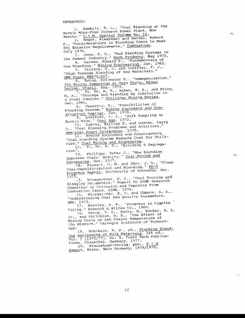
REFERENCES
1 ~ Gambill, T. L .. , "Coal Blending at the Navajo Mine-Four Corners power Plant, New Mexico," C. I.N. special volume No. 12.
2. Bogot, Alexander and Hensel, Robert P., "Considerations in Blending Coals to Meet S02 Emission Requirements," Combustion, July 1978.
3. Snow, F. 0., "Bed Blending Systems in the Cement Industry," Rock Products, May 1970.
4. Larsen, Edward P .. , "Fundamentals of are Blending," Mining Engineering, Jan. 1962.
5. Viciana, J. J. and Loeffler, F. J., "High Tonnage Blending of Raw Materials," 5MB Paper #MS75-657.
6. Ewing, sylvester E., "HOmogenization," 5th Mining Symposium at Ouro PretO. Minas Gerias. Brazil, Aug. 1975.
7. Yu, Dr. A. T., Aiken, W. S., and Price, B. A., "Storage and Blending by Simulation in a Steel Complex," Skillings Mining Review, Dec. 1969.
8. Veenstra, H., "possibilities of Blending System," Robins Engineers and Constructors Seminar, Jan. 1970.
9. Loeffler, F. J. I "Bulk Sampling at Navajo Mine," Coal Age, 1972.
10. Sabina, William E. and Duncan, Larry D., "coal Blending Problems and Solutions," American power Conference, 1978.
11. Robins Engineers and Constructors, "Coal Blending System Reduces Cost for Utilities," Coal Mining and Processing.
12. Yu, Dr. A. T., "Blending & Segrega -
tion" . 13. Phillips, Peter J., "How Blending
Improves Coals' Quality," Coal Mining and processing, Oct. 1977.
14. Stewart, a. w. and Shou, J. K., "Clean Coal-Desulfurization and Blending," PD-9 Progress R~~rt, University of Kentu~ Oct.
1975. 15. Winegartner, E. c., "Coal Fouling and
Slagging Parameters 1" Report by ASME Research Committee on Cor~osion and Deposits From Combustion Gases, ASME, 1974.
16. Winegartner, E. C. and Ubbens, A. A., "understanding Coal Ash Quality Parameters,
SME. 1975. 17. Markley, G. F., "Progress in Lignite
Firing," Babcock & Wilcox Co., 1968. 18. Estep, T. G., Seltz, H., Bunker, Ha L.
Jr., and strickles, H. S., "The Effect of Mixing Coals on Ash Fusion Temperature of the Mixture, 11 Carnegie Institute of Technol-
ogy. 19. wohlbier, R. H. t ed., Stacking Blend-ing Recla~in~~ulk Materials. 1st ed., Vol. 1 (1975/77), No.5, Trans Tech publications, Clausthal, Germany, 1977.
20. Krausskopf-Verlag, pub •. F + H Export, Mainz, West Germany, 1978/1979.
12