Embed Size (px)
Citation preview
J. La Favre 3/2/17
1
Onshape Lesson 7
In this lesson you will make a spur gear. Making gears is a more advanced lesson than the previous six, but if you are eager to learn how, this lesson will get you started. You will need to learn some technical terms and mathematical formulas before creating your gear.
There are four circles in the drawing to the left you need to know: 1) the Outside Diameter (OD), which is the circle surrounding the tips of the gear teeth 2) Pitch Diameter (PD), which is the circle about half-way into the depth of the gear teeth 3) Root Diameter, which is the circle at full depth of the teeth and 4) Base circle. You will start drawing your gear by drawing the first three circles and you will need to know the diameters of these circles.
Diametral Pitch (DP) is an important specification for a set of gears. Gears must have the same pitch for proper meshing. Diametral Pitch is defined as the number of teeth per inch of Pitch Diameter.
It is common for the engineer to select a value desired for DP and then use formulas to calculate the other dimensions needed for the gear system.
In this exercise you will duplicate the 40 tooth gear of the Tetrix Max system that we use in our club. The Tetrix Max gears have a DP of 32 teeth per inch. The Pressure Angle (PA) is 20 degrees. PA is the angle at which gear teeth contact each other (see drawing above). The face width of the gear is 0.25 inches. You now have all necessary information to make your calculations.
N = number of teeth = 40
DP = Diametral Pitch = 32
Outside Diameter = OD = (N+2)/DP = 42/32 = 1.312
Pitch Diameter = PD = N/PD = 40/32 = 1.25
Root Diameter = RD = (N-2)/DP = 38/32 = 1.187
Quarter Angular Circle Pitch = 4ACP = (360/4)/N = 90/40 = 2.25
Pitch Point Diameter Circle = PPD = ¼ PD = 0.25 X 1.25 = 0.312
J. La Favre 3/2/17
2
We now have all the values needed to make the gear.
1. Create a new document and name it Lesson 7. 2. Create a new sketch on the top plane and set the view normal to the sketch plane.
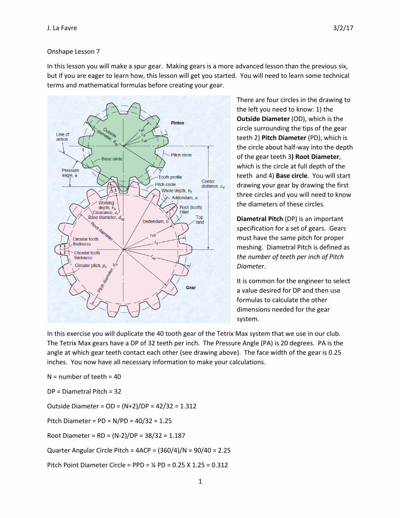
3. Select the Circle tool and draw three circles centered on the center point of the top plane.
Use the Dimension tool to set the diameters of the circles to 1.312, 1.25, and 1.187 inches (OD, PD and RD).
4. Check to make sure there are no tool buttons selected (click a button if it is blue to turn it off). Then click with the mouse on the outer two circles to select them. Then click on the
Construction tool to convert the lines into construction lines.
J. La Favre 3/2/17
3
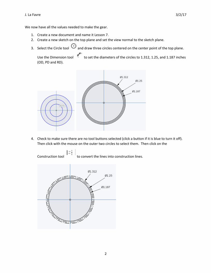
5. Select the Line tool . Draw a vertical line from the center of the top plane to just above the outer circle. Draw another line from the center, angled to the left (see illustration below).
Select the two lines just drawn and then click on the Construction tool to convert the two lines to construction lines.
6. Select the Dimension tool and set the angle between the two lines to 2.25 degrees (the Quarter Angular Circular Pitch).
J. La Favre 3/2/17
4
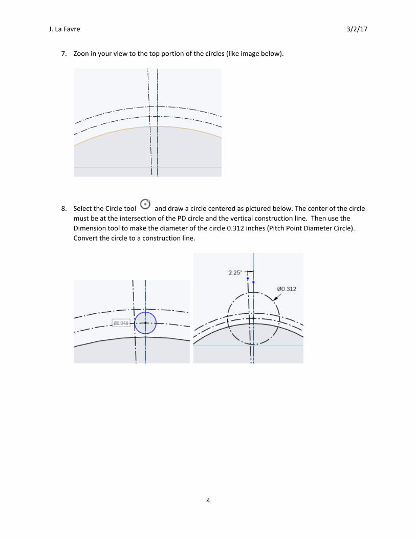
7. Zoon in your view to the top portion of the circles (like image below).
8. Select the Circle tool and draw a circle centered as pictured below. The center of the circle must be at the intersection of the PD circle and the vertical construction line. Then use the Dimension tool to make the diameter of the circle 0.312 inches (Pitch Point Diameter Circle). Convert the circle to a construction line.
J. La Favre 3/2/17
5
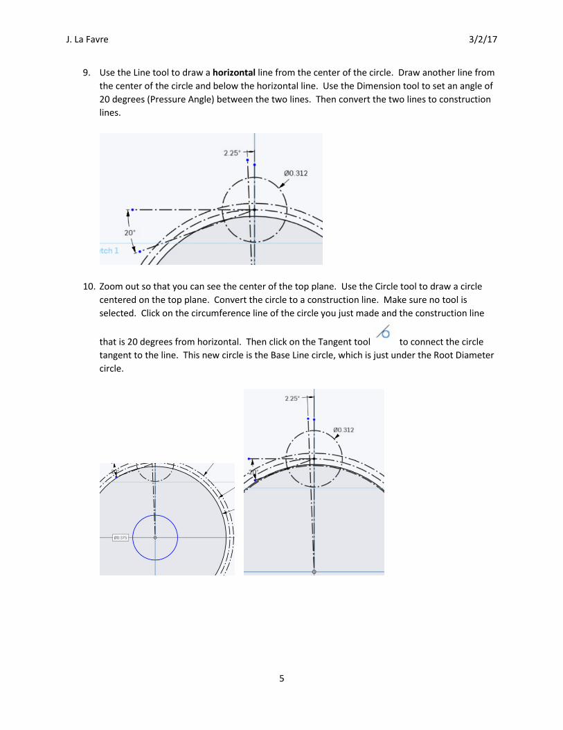
9. Use the Line tool to draw a horizontal line from the center of the circle. Draw another line from the center of the circle and below the horizontal line. Use the Dimension tool to set an angle of 20 degrees (Pressure Angle) between the two lines. Then convert the two lines to construction lines.
10. Zoom out so that you can see the center of the top plane. Use the Circle tool to draw a circle centered on the top plane. Convert the circle to a construction line. Make sure no tool is selected. Click on the circumference line of the circle you just made and the construction line
that is 20 degrees from horizontal. Then click on the Tangent tool to connect the circle tangent to the line. This new circle is the Base Line circle, which is just under the Root Diameter circle.

J. La Favre 3/2/17
6
11. Zoom your view in as seen in image below.
12. Draw a circle with its center point at the intersection of the circle with the 20 degree line as seen below.
J. La Favre 3/2/17
7
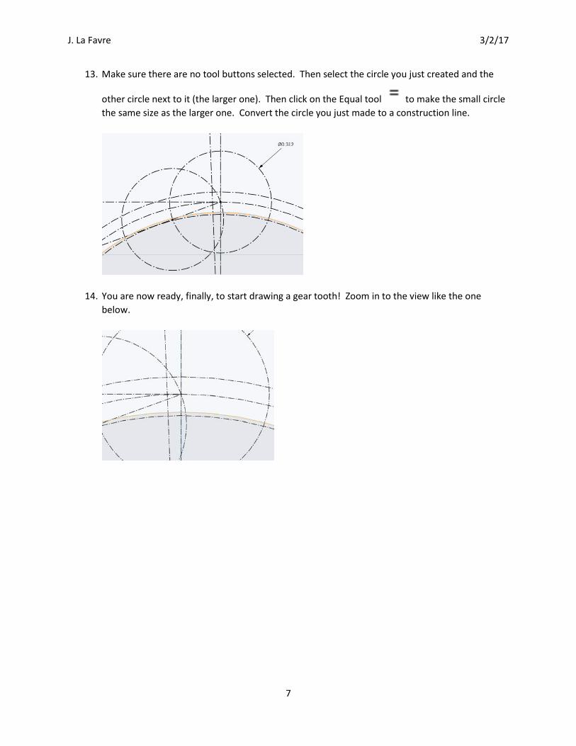
13. Make sure there are no tool buttons selected. Then select the circle you just created and the
other circle next to it (the larger one). Then click on the Equal tool to make the small circle the same size as the larger one. Convert the circle you just made to a construction line.
14. You are now ready, finally, to start drawing a gear tooth! Zoom in to the view like the one below.

J. La Favre 3/2/17
8
15. Select the 3 point arc tool . You will draw two arcs with the tool. The first arc is shown below to the left. Click on the point of the intersection of the outer diameter circle and the last circle you made (point 1). Then move mouse cursor down and click on point 2. Then move mouse cursor to position 3 (on the circle line) and click to set the arc. The arc should be on top of the circle construction line. Make another arc line below and connecting to the first arc as seen in the image to right below. Make sure no tool buttons are selected. Then select both arc
lines. Finally, select the Tangent tool to make the two arcs tangent to each other. You may have a hard time selecting the arcs instead of the circle construction line at the same place. Move the mouse slowly horizontally across the lines and click, repeating until you select the solid arc line, not the dashed construction line.
J. La Favre 3/2/17
9
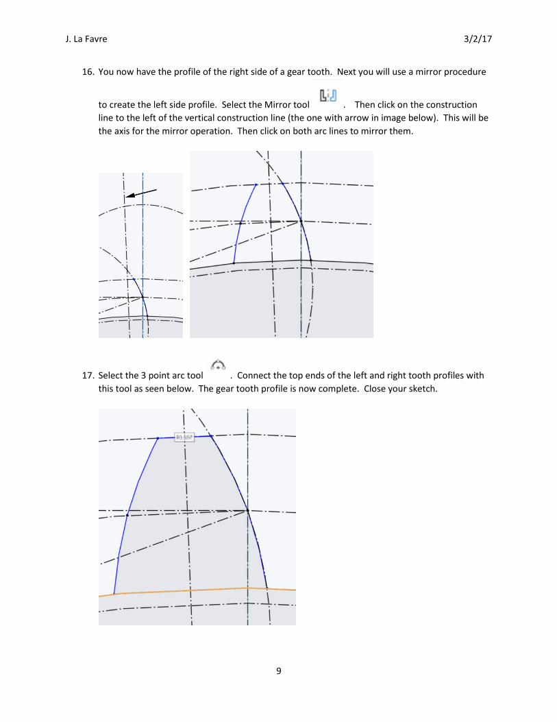
16. You now have the profile of the right side of a gear tooth. Next you will use a mirror procedure
to create the left side profile. Select the Mirror tool . Then click on the construction line to the left of the vertical construction line (the one with arrow in image below). This will be the axis for the mirror operation. Then click on both arc lines to mirror them.
17. Select the 3 point arc tool . Connect the top ends of the left and right tooth profiles with this tool as seen below. The gear tooth profile is now complete. Close your sketch.
J. La Favre 3/2/17
10
18. Select the Extrude tool . Click on both the large circle and the gear tooth to extrude both to a thickness of 0.25 inches. Then close the extrude.
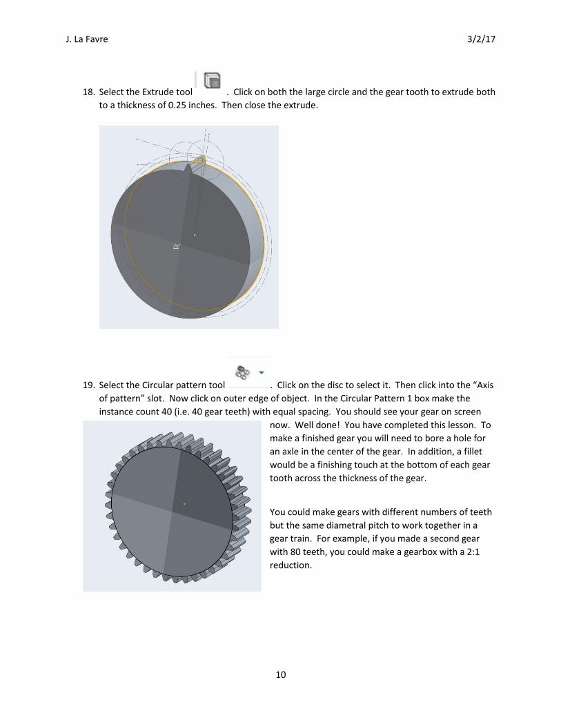
19. Select the Circular pattern tool . Click on the disc to select it. Then click into the “Axis of pattern” slot. Now click on outer edge of object. In the Circular Pattern 1 box make the instance count 40 (i.e. 40 gear teeth) with equal spacing. You should see your gear on screen
now. Well done! You have completed this lesson. To make a finished gear you will need to bore a hole for an axle in the center of the gear. In addition, a fillet would be a finishing touch at the bottom of each gear tooth across the thickness of the gear.
You could make gears with different numbers of teeth but the same diametral pitch to work together in a gear train. For example, if you made a second gear with 80 teeth, you could make a gearbox with a 2:1 reduction.