Embed Size (px)
Citation preview

REVIEW ARTICLE
Microfluidics and photonics for Bio-System-on-a-Chip:A review of advancements in technologytowards a microfluidic flow cytometry chip
Jessica Godin1, Chun-Hao Chen1, Sung Hwan Cho1, Wen Qiao2; 1, Frank Tsai1 and Yu-Hwa Lo1
1 University of California, San Diego, Department of Electrical and Computer Engineering, La Jolla, CA, USA2 Zhejiang University, State Key Laboratory, National Engineering Research Center (NERC) for Optical Instrument,
Zhejiang, Hangzhou, China
Received 28 March 2008, revised 1 May 2008, accepted 5 May 2008Published online 5 June 2008
Key words: Biomedical instrumentation and transducers, including micro-electro-mechanical systems (MEMS), cells on achip, other integrated-optical elements and systems, fabrication techniques; lithography, pattern transfer, flows in micro-electromechanical systems (MEMS) and nanoelectromechanical systems (NEMS), fluorescence
PACS: 87.85.Ox, 87.85.dh, 42.82.Gw, 42.82.Cr, 47.61.Fg, 87.64.kv
# 2008 by WILEY-VCH Verlag GmbH & Co. KGaA, Weinheim
1. Introduction
Over the past decade, the field of microfluidics hasbegun to show great promise for research assays anddiagnostics as well as for clinical applications. The
field has evolved from devices comprised of simplemicrofluidic channels into complex devices that canmix fluids [1], pump liquids [2], perform digital logic[3–6], individually culture cells [7], determine opti-mal reaction conditions [8], and much more. Small-
# 2008 by WILEY-VCH Verlag GmbH & Co. KGaA, Weinheim
Journal of
BIOPHOTONICS
Microfluidics and photonics come together to form afield commonly referred to as ‘optofluidics’. Flow cyto-metry provides the field with a technology base fromwhich both microfluidic and photonic components be de-veloped and integrated into a useful device. This articlereviews some of the more recent developments to famil-iarize a reader with the current state of the technologiesand also highlights the requirements of the device andhow researchers are working to meet these needs.
A microfluidic flow cytometer protoype employing on-chip lenses for illumination and light collection in con-junction with a microfluidic sample flow system for de-vice miniaturization.
*Corresponding author: e-mail: [email protected]
J. Biophoton. 1, No. 5, 355–376 (2008) / DOI 10.1002/jbio.200810018

scale fluidic devices, by definition, will have a lowReynolds number, making controlled laminar flowsystems easily achievable. Microfluidics further of-fers the advantages of small size for miniaturizationand parallelization of devices. Furthermore, thissmall size opens the door to the potential of portabledevices. Additionally, typical fabrication processesoften readily lend themselves to mass production,potentially helping to create lower-cost devices. Withthese advantages, the idea of low-cost lab-on-a-chipdevices can start to become a reality [9]. Such de-vices would be very useful to researchers, clinical la-boratories, and point-of-care clinicians in remoteand/or resource-poor settings.
The functionality of microfluidics will expandgreatly if these devices can be combined with photo-nics to create a new technology platform: integratedmicrofluidic photonics, often referred to as optoflui-dics [10]. Embracing photonics is a logical path ofevolution for microfluidics, as the most popular tech-niques for biological and chemical detection arephotonic in nature. Fluorescence, fluorescence reso-nance energy transfer (FRET), optical scattering, andsurface-enhanced Raman spectroscopy (SERS) aresome the most effective and accurate methods to de-tect analytes at the cellular and molecular level. Inte-gration of microfluidics with photonics represents notonly a new technology platform but also a transfor-mation to the new paradigm of bio-system-on-a-chip(BSoC) [11]. As electronic integrated circuits havetransformed the world of electronics, integrated mi-crofluidic photonic circuits hold the promise to revo-lutionize the field of biomedicine. In spite of the rapidadvances in microfluidics and photonics, however, thefield is admittedly still in its embryonic stage. Techno-logical innovations and breakthroughs are needed todemonstrate the performance and cost advantages of-fered through miniaturization and integration. Giventhe diversity of the applications, target application isneeded to guide the technology development; a bio-system that is not only the workhorse for the industrybut also a test vehicle to assess and benchmark thetechnology. The flow cytometer, or FACS (fluores-cence-activated cell sorter), is just the candidate tomeet these requirements.
Flow cytometers are commonly-used researchand clinical tool in which the properties of each com-ponent of a sample, such as cells, are individuallymeasured. A flow system brings cells one by onepast an interrogation point, where they are illumi-nated by a light source. Typically the system iscomprised of fluid flow through a small laser beam.As each analyte is illuminated, it scatters light witha characteristic directional intensity distribution.Further, fluorescently tagged antibodies are oftenused to mark and identify cells (immunofluores-cence). Fluorescence may also be measured whenstains are used (to quantify DNA content, show cell
viability, etc), or when fluorescent proteins are pre-sent (for example when used as reporters in researchsettings). Thus light scattered from the cell and oneor more colors of fluorescence emitted from the illu-minated cell are measured, providing a number ofparameters to yield statistics about the samples sub-populations. In addition, many machines have a sort-ing apparatus to isolate analytes of interest forfurther study.
The development of new cytometers is typicallyfocused on either enhancing performance (higherthroughput, more measurable parameters) or in-creasing accessibility (smaller, less expensive ma-chines). The cytometer is almost inherently micro-fluidic in nature, rapidly interrogating small volumesof fluid. Taking the cytometer to a microfluidic plat-form could transform the device into a smaller, pos-sibly mass-producible machine, and may be able toaddress performance enhancement as well. The costof the cytometer, currently around $30,000 for morebasic research models and more typically on theorder of $100,000, could be significantly lowered,opening up new markets that were previously inac-cessible due to prohibitive costs. Additionally, micro-fluidic cartridges could potentially be disposable,supplying a sterile device as well as containing andlimiting exposure to biohazardous materials such asblood. Disposable devices also bypass the issue ofdevice clogging, a problem experienced in benchtopcytometry, by allowing the user to quickly replacethe microfluidic cartridge and continue their work.Microfluidic devices may further be able to reducethe sample size necessary for some assays, such asT-cell enumeration for HIV patients, limiting theamount of blood needed from patients as well asreducing the necessary volume of costly reagents,helping to lower testing costs.
As with any new technology platform, though,there are a number of obstacles that must be over-come to realize a practical microfluidic flow cyt-ometer. Recent research has made great headway ona number of fronts. This article takes a look at recentprogress towards the achievement of a lab-on-a-chipflow cytometer. The basic cytometer includes (i) afluidic system, (ii) an optical interrogation system andsystems for light collection, and often (iii) a cell sort-ing apparatus. Advances pertaining to each of thesecomponents will be discussed.
The Basics of Flow Cytometry
There are many sources that give excellent, detaileddescriptions of the nature and history of flow cyt-ometers, as well as their operation and applications[12, 13]. These references will give a comprehensivetutorial on flow cytometry; to balance completeness
J. Godin et al.: Microfluidics and photonics for Bio-System-on-a-Chip356
Journal of
BIOPHOTONICS
# 2008 by WILEY-VCH Verlag GmbH & Co. KGaA, Weinheim www.biophotonics-journal.org
and brevity, only a brief overview will be given here.To create a usable microfabricated flow cytometer,the necessity and use of each of the basic compo-nents of the benchtop device must be understoodand considered.
The device contains a fluidic system for pumpingboth sheath flow and sample flow through the flowchamber. The interrogation source is typically a la-ser, 488 nm being the standard for flow cytometry.Many commercial instruments include multiple lightsources, especially more high-end devices. Manynewer instruments now employ lower-powered,smaller solid state lasers. Low-cost devices alreadytend to use alternative wavelength (such as 532 nm)diode lasers as their main sources, and violet laserdiodes (VLDs) have recently received a great dealof attention as the next possible low-cost biomedicallaser source [14].
The basic concept of flow cytometry is to uselight signals to identify a cell in flow. For the ma-chine to work, light must be collected from a singlecell at a time with enough fidelity to ensure accurateinterpretation. This means that the interrogationconditions of each cell must be identical to that ofthe last (light intensity, beam width, cell location indetection area). Light must be collected from ahighly localized area to prevent cross-talk, and col-lected background light must be low enough to allowthe resolution of a clear signal.
Both scattered light and fluorescence are gener-ally collected by a flow cytometer. Two light scatter-ing collection lines, for forward scatter collection(FSC) and side scatter collection (SSC), are typicallyused. Forward scatter generally requires the use of abeam stop to prevent direct receipt of the illumina-tion source. As a particle passes through the illumi-nation beam, an increase in light intensity will berecorded from the forward scatter line. The relativeintensity is indicative of the particles identity, due tofactors such as its size and refractive index. If thebeam block is absent, the light collected is ‘extinc-tion’; that is, the detector will measure a dip in lightintensity due to scattering from and absorption bythe particle. This measurement is unusual in com-mercial devices. The side (or ‘orthogonal’) scatterline is traditionally centered perpendicular to theaxis of illumination. The relative light intensity re-corded on the SSC line as a particle passes is alsoindicative of the particles identity, generally relatedto the internal granularity of the particle. In additionto light scatter, several bands of fluorescence (FL)from the particle are often collected. A simple ma-chine might include only 3 fluorescence channels,whereas more high-end instruments might have10 or more. Each light collection line terminates ina photodetector, generally a photomultiplier tube(PMT). Forward scatter lines often employ a simplephotodiode, due to their lower cost and the rela-
tively high light intensity seen on the FSC line. Thefluorescence line will further require dichroic mir-rors, to split the beam off to several detectors basedon wavelength bands, and optical filters, to definethe band of light passed to each fluorescence detec-tor. The measured signal intensities for each param-eter are used to distinguish between various sam-ple subpopulations (e.g. monocytes, lymphocytes,and granulocytes in a leukocyte sample).
After optical detection and cell analysis, the sort-ing of targeted cells is performed downstream of thecytometer. As cells approach the sorting chamber, vi-brations break the stream up into charged droplets,which in turn carry the cells down to a pair ofelectrically charged deflecting plates. Through a feed-back control system (e.g. the decision making processafter the cell is detected and identified upstream), thepolarity of the plates changes to deflect cells of inter-est into the collection tube. Typically the sorting rateis on the order of 10,000–100,000 cells/s and is limitedby the speed individual droplets that can be formed.
The Microfluidic Cytometer
At its simplest, microfluidic flow cytometry chip con-sists of a simple microfluidic channel for sampleflow. Detection is accomplished by focusing a laserinto the channel and coupling out light (generallyvia microscope objective) to a PMT, CCD, or APD[schematic]. Fluidic control is accomplished via grav-ity fed systems, syringe pumps, or similar mechan-isms. Some of the earliest microfluidic cytometrydevices were created using techniques that had beenstreamlined by electronics microfabrication techni-ques. Channels would be etched into silicon sub-strates [15, 16] and sealed by the bonding of lid, suchas glass. These devices offered the benefits of mass-producibility and low sample volume usage (thuslow reagent volume usage). Glass-etched devicesoffered increased flexibility in laser and detector pla-cement and also lowered sidewall reflections due tothe use of an optically transparent substrate.
With the advent and popularization of soft litho-graphy techniques [17] (and the associated polymerreplica molding techniques), the field of microfluidicshas begun to take off. In this process, photolithogra-phy techniques are used to create a ‘mold’ fromwhich polymer ‘replicas’ can be generated. Devicescould now be rapidly and inexpensively prototyped,as design changes simply require the printing of newhigh-resolution transparency mask. Thus, polydi-methylsiloxane (PDMS) based devices have becomethe vehicle of choice for many researchers, includingthose in the area of microfluidic flow cytometry.
In addition to rapid, inexpensive prototyping,PDMS also offers simple processing techniques.
J. Biophoton. 1, No. 5 (2008) 357
REVIEWREVIEWARTICLEARTICLE
# 2008 by WILEY-VCH Verlag GmbH & Co. KGaA, Weinheimwww.biophotonics-journal.org
After the initial mold fabrication and coating with ahydrophobic release agent, the processing does notrequire harmful acid-based chemistry that is com-mon in other fabrication methods, such as directetching of channels into glass or silicon. PDMS is anoptically transparent elastomer, a good choice forthe molding process and also for creating devicesthat will be optically interrogated. There are a num-ber of methods for bonding PDMS to glass, poly-mers such as PDMS, and other materials; thesemethods include including partial-cure bonding [18],oxygen plasma or UV/Ozone treatment [19], coronaactivation [20], etc. Polymer-based microfluidic cyt-ometers became more and more common. With theemphasis off of channel fabrication techniques, morerecent research has focused on some different prob-lems, including optical system improvement and on-chip cell sorting.
I. The Fluidic System
In a conventional flow cytometer, the potential fortwo or more particles to simultaneously enter theoptical interrogation region is minimized by the useof flow focusing, or confining the sample flow to avery narrow stream by using the pressure of a sur-rounding sheath flow stream. Flow focusing furtherensures uniform particle velocity by removing thesample flow from contact with the flow cell walls,reducing the parabolic flow profile that would other-wise exist. Variations in particle velocities would notonly undermine the reliability of the detected sig-nals, they can also cause synchronization problemsdownstream for cell sorting. Flow focusing ensuresthe quality, reliability, and reproducibility of the col-lected signals, and thus the incorporation of effectivefocusing modules into a microfluidic flow cytometeris critical. For these reasons, significant efforts havebeen made toward developing focusing methods thatallow both two-dimensional (2D) and three-dimen-sional (3D) confinement.
A. Two-Dimensional Flow Focusing
Two-dimensional (2D) hydrodynamic flow focusinghas been the most widely used techniques for parti-cle confinements and has been applied to a numberof applications, including multiple-outlet flow-switch-ing [21], enumeration of beads [22] and cells [23],and deformation of DNA [24]. By adjusting the rela-tive pressures of the sample inlet and the twosheath-flow channels, which lie perpendicular to thesample channel, Knight et al. have focused the sam-ple flow stream down to �50 nm inside of a 10 mm
channel [25]. They have also developed a mathema-tical model to relate the focused width to flow resist-ances of the inlet, side, and outlet channels [25]. Onthe other hand, Lee et al. have extensively studiedthe effects of the relative flow rates as well as thechannel aspect ratios on the width of the focusedstream, both numerically and experimentally, forboth circular [26] and rectangular [27] channel con-figurations. They have shown that the focused beamcan be reduced down to the same order of magni-tude of micron-sized particles for a circular channeldiameter of 2.4 mm. Hydrodynamic focusing canalso be achieved by applying suction at the deviceoutlet [28, 29], which can allow fluid focusing withonly a single syringe pump [29]. In addition, ratherthan using sheath liquids, air can be used as thesheath fluid to confine sample flow [28]. Under thesame outlet suction pressure (�45 mm Hg), as thesample flow rate decreases down to a critical level(�5 ml/hr), flow stream becomes unstable and be-gins to break into individual droplets downstream.This feature may be attractive for microfluidic flowcytometers, as the formation of cell-containing dro-plets can facilitate in screening and sorting of singleparticles or cells. Moreover, the method can elimi-nate the need for large sheath reservoirs, loweringthe cost of operation and also eliminating the needfor a clean fluid source for on-site operation in non-urban settings.
In addition to using pump-induced force to con-strain flow, focusing can also be achieved with elec-trokinetically-driven flow. Electrodes are insertedinto fluidic channels and as DC bias is applied acrossthe electrodes, electroosmotic flow is generated [30].As sample flow enters the focusing region, wherethe three streams meet, the electroosmotically-in-duced flow will confine the sample stream (Figure 1),with the width of the focused sample stream depend-ing on the relative electric field strength between thesample channel and the side channels. Schrum et al.have confined a sample stream containing 0.97 mmand 1.94 mm latex particles into an 8 mm streaminside of a 50 mm channel using a field strengthratio of �0.15 (100 V/cm and 700 V/cm at the sam-ple channel and side channels, respectively) at athroughput of 34 particles/s [30]. Researchers haveapplied this electrokinetic focusing technique to avariety of applications including detection and sort-ing of DNA molecules [31], controlled sample pluginjections of various sizes [32], and flow-switching[33]. Although adjusting the electrokinetically-fo-cused beam size is relatively straightforward, instan-taneous, and accurate, the required use of high vol-tage (on the order of kV) renders this techniqueimpractical in most flow cytometric applications,since these high electric field can cause irreversibledamage in the integrity of most biological agents(e.g. cells, proteins, etc).
J. Godin et al.: Microfluidics and photonics for Bio-System-on-a-Chip358
Journal of
BIOPHOTONICS
# 2008 by WILEY-VCH Verlag GmbH & Co. KGaA, Weinheim www.biophotonics-journal.org

B. Three-Dimensional Flow Focusing
Although the conventional 2D hydrodynamic focus-ing involves two outer sheath flows on each side of acentral sample flow to laterally constrain the sampleflow, it is problematic due to the lack of verticalfocusing. In the vertical direction, fluid drag alongthe walls creates a parabolic flow distribution, theresult of which is a wide distribution of sample flowvelocities. This can be problematic in terms ofcross-talk; a slow cell may be ‘caught up’ to by afaster cell, resulting in more doublets (two cellsbeing interrogated simultaneously). Additionally, thevelocity distribution can result in variations in thedetected signal from an otherwise homogenous po-pulation due to different integration times at thedetector or differing illumination intensities from anonuniform illumination beam. Lastly, for high-
speed, high accuracy cell sorting, an exact knowledgeof the cells location is critical. All these factorscontribute to a strong interest in developing three-dimensional (3D) focusing devices capable of confin-ing small quantities of cells/particles in both horizon-tal and vertical directions. Generally speaking, thereare two kinds of approaches reported for achieving3D focusing of cells/particles in microfluidic chan-nels: dielectrophoresis (DEP) and 3D hydrodynamicfocusing.
Dielectrophoresis (DEP) is a phenomenon inwhich a force is exerted on a dielectric particle whenit is subjected to a non-uniform electric field. Morganet. al. demonstrated that DEP can be used to focusnanoscale latex particles as small as 40 nm in di-ameter [34]. Lin et al designed a flow cytometer with3D focusing capability which was able to focus thesample stream to a width of 8 mm [35]. This featurewas realized by a combination of 2D hydrodynamicforces as horizontal focusing and negative DEPforces as vertical focusing. But DEP has several in-trinsic drawbacks: 1) device making requires complexfabrication process such as e-beam evaporation andprecise electrode-to-substrate alignment, 2) Electricfield generation entails extra electronics, and 3) li-quids with specific conductivities are needed for dif-ferent particles, since The DEP force heavily dependsboth on the nature of the particles being focused aswell as on the nature of the fluid suspension.
Unlike dielectrophoresis, 3D hydrodynamic fo-cusing acts on the fluid rather than on the particles.
Figure 1 Time-integrated image (5 sec exposure time)showing the effects of electrokinetic focusing as electricfield strengths of 100 and 300 V/cm are applied to sampleand focusing (side) channels, respectively. The arrows re-present both the direction of fluid movement and the rela-tive fluid velocities in each channel. Reprinted with per-mission from [30]. Copyright 1999 American ChemicalSociety.
Figure 2 (online color at: www.biophotonics-journal.org)Schematic of the 3D hydrodynamic focusing process by em-ploying the “microfluidic drifting” technique. Slices 1–10are the cross-sectional profiles of the fluorescein dye con-centration in the focusing device. Inset: the simulation ofthe secondary flow velocity field shows the formation ofDean Vortices in the 90-degreee curve. An iso-curve offluorescein concentration ¼ 25 mM is arbitrarily chosen asthe boundary of the sample flow [42]. Reproduced by per-mission of The Royal Society of Chemistry.
J. Biophoton. 1, No. 5 (2008) 359
REVIEWREVIEWARTICLEARTICLE
# 2008 by WILEY-VCH Verlag GmbH & Co. KGaA, Weinheimwww.biophotonics-journal.org

It is achieved by completely surrounding the sampleflow by sheath flow that constrains the sample flowto the center of the channel in both the lateral andthe vertical dimensions. Klank et al simulated andfabricated a “chimney” structure in silicon by reac-tive ion etching [36, 37]. The coaxial sample sheath-ing was obtained by injecting a sample into thesheath flow in a perpendicular direction. However,the disadvantage is that the fabrication process isvery complicated. Three-dimensional focusing hasalso been achieved using clever, multi-layered 3Dmicrofluidic devices [38–41]. Most recently, Maoet al demonstrated a “microfluidic drifting” techni-que that enabled 3D hydrodynamic focusing with asimple single-layer planar microfluidic device fabri-cated via standard soft lithography [42]. Sample flowwith a total height of less than 15 mm was obtainedby the transverse secondary flow induced by thecentrifugal effect in a curved microfluidic channel(Figure 2). This chip, which does not require assem-bly of individual components or multiple alignmentsand exposures during mold fabrication, is easy tofabricate and mass producible.
II. The Optical System
Initially, microfluidic chips were looked at as a repla-cement for the flow cuvette of the cytometer; all ofthe optical systems remained essentially the same,and often this is still the case [15, 36, 40]. For porta-ble systems, the size and weight of the light collec-tion system is an important consideration. Utilizing abulk optical system drastically reduces the benefitsof miniaturizing the fluidic platform by overshadow-ing the gains of miniaturization. Ideally, the opticalsystem would scale down in size with the fluidic sys-tem while maintaining both the low system cost andthe possibility for mass production. Additionally, re-ducing the size of the optical system would reducethe total optical path length, which may reduce ab-sorption losses, an important consideration in fluor-escence measurements. To address these issues, someresearchers considered collecting light in close proxi-mity to the channel by using lower-cost, small photo-detectors such as avalanche photodiodes [19, 43]placed above or below the chip, making a more com-pact device. This approach wont work for multi-parameter detection, however, limiting its utility forflow cytometers.
A more recent approach by Kostner et al, amongothers, has been the use of CD or DVD pickupheads as small, low-cost, and low-powered optical in-terrogation and collection systems [44]. The authorswere able to detect and differentiate between poly-styrene beads and erythrocytes. Cells and beads areof course very different in optical properties; how-
ever, future improvements and investigations couldgreatly improve upon this promising approach. Ad-ditionally, the work would likely need to be ex-panded to encompass multi-parameter detection (i.e.fluorescence) to create a more practical device.
A. Optical Fibers
By the 1980s, the cytometry community had startedto make use of optical fibers in their machines andhad even begun to consider the possibility of repla-cing conventional bulk optics with optical fibers [12].Many in the microfluidic flow cytometry researchcommunity also began to investigate the use of alter-native optics. Pamme et al. used fibers held at fixedangles above the fluidic channel to collect light scat-ter at 15� and 45� while using a lamp for sample illu-mination. Light scattering CVs were typically 25–30%; quite an achievement for a microfluidic devicebut considerably larger than the expected 5% varia-tion that might be expected from a benchtop device[22]. The authors attributed this large signal distri-bution to effects such as scattering from sidewallroughness, illumination beam imperfections, andcross-talk. Chabinyc et al. also employed fibers, inte-grating them on the chip by first clamping them tothe mold in close proximity to the microfluidic chan-nel and then pouring PDMS to make the mold repli-ca around them [19]. The glass-PDMS adhesion dur-ing polymer curing yielded a robustly-integratedoptical fiber that required no index matching fluid.The method still requires some alignment and as-sembly, a problem which is often avoided by the useof fiber sleeves. In this approach, the mold includesa channel into which the fiber is inserted after poly-mer curing and epoxy-fixed in place [45]. The fibersleeve approach can also avoid the use of indexmatching liquids by filling the airspace instead witha curable liquid, often the very same heat-curablepolymer used to make the device itself [46].
B. Integrated Waveguides
Waveguides offer similar light-confinement capabil-ities to optical fibers but in a more robustly inte-grated fashion. Such chips would directly interfacewith light sources and detectors, making for a simpletestbed that readily allows for chip changes. On-chipwaveguides can be used to direct light to targets, suchas detectors within microns of the illuminated sampleswithout the difficulties of alignment, epoxy-fixing, orbreakage. On chip waveguides fabricated by oxide de-position [47] or ion exchange [48] have been appliedto on-chip detection systems. Anisotropic silicon etch-
J. Godin et al.: Microfluidics and photonics for Bio-System-on-a-Chip360
Journal of
BIOPHOTONICS
# 2008 by WILEY-VCH Verlag GmbH & Co. KGaA, Weinheim www.biophotonics-journal.org
ing has been also utilized to form metalized siliconwaveguide grooves capped by metal strips. In this ap-plication, optical coupling between the waveguidesand microchannels is achieved by reflection from theend-facets of the waveguides [49]. Many these meth-ods, however, require complex and lengthy fabricationprocess, and often the materials are not well-suited forbiological applications or for visible light.
S. H. Huang et. al. fabricated a monolithic, two-layered TIR (Total Internal Reflection)-based micro-fluidic chip using SU-8 photoresist to create planarwaveguides [50]. An SU-8 microprism directed in-coming light into the slab waveguide. The analyteswere located above the waveguide. This monolithicintegration allows for a higher coupling efficiencyfrom the fiber into the waveguide (without the needfor index-matching oils) and low reflectance loss onthe interfaces. This polymer-based waveguide hassome advantages over the non-polymer based tech-niques mentioned above such as low-cost fabrication,relatively simple processing, and ease of alignment,which is important for light coupling efficiency.
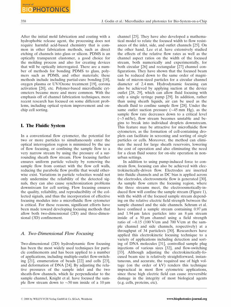
Monolithic waveguide integration of polymerwaveguides made by PDMS with microfluidic chan-nels is an attractive approach due to simple channelsealing, device robustness, good material opticalproperties, and precise alignment of waveguides andmicrochannels [51]. V. Lien demonstrated monolithicintegration of microfluidic channels and waveguidesin PDMS-based devices [52]. A higher refractiveindex PDMS (n ¼ 1.42) was injected into core chan-nels surrounded by cladding layers of lower refrac-tive index PDMS (n ¼ 1.407). This cost-effectivemethod demonstrates simple prealignment andenables optical coupling between the channels andwaveguides. Figure 3(a) and (b) show, respectively aprealigned waveguide structure and a side view of adevice waveguide emitting fluorescent light [51].Since the waveguides and the microchannels areself-aligned by photolithography during the moldfabrication, no fine alignment using microscopetranslation stages or mico-positioners is needed dur-ing fabrication.
Bliss et. al. similarly demonstrated a liquid opticalwaveguide by injecting high refractive index liquid
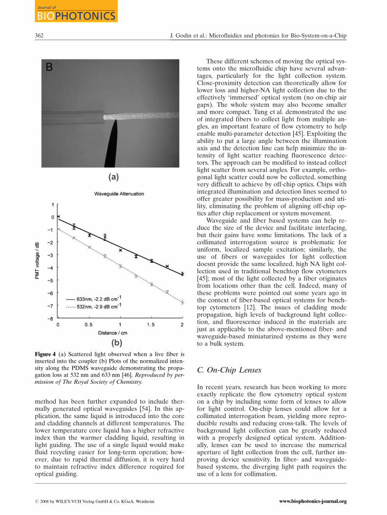
PDMS prepolymer into the prealigned microfluidicchannels [46]. By introducing uncured PDMS intothe microfluidic channels as the core material of thewaveguide, this method allows for cleaning and reus-ing of the waveguide channel. As is often done fortesting waveguide-based devices, optical coupling be-tween the liquid PDMS waveguides and light sourceor detectors was achieved through optical fibers in-serted into the liquid-core waveguides at the edge ofthe microfluidics chips. The liquid PDMS pre-poly-mer coats the inserted fiber, reducing reflections andscattering at the optical interface, thus increasing thelight coupling efficiency. The method of index match-ing works for cured waveguides as well. Figure 4(a)shows observed scattered light at the interface of theinserted optical fiber and uncured PDMS prepoly-mer waveguide. The measured loss was 2.9 dB cm�1
and 2.2 dB cm�1 at 523 nm and 633 nm, respectively.Figure 4(b) shows a plot of normalized waveguideattenuation for two different wavelengths. The lightpropagation loss seems to be mainly due to surfacescattering by the sidewall roughness of the mold.Waveguide attenuation could be dramatically re-duced if surface roughness is decreased by improve-ments in the mold fabrication process.
Whitesides’ group has been working on liquid-core/liquid-cladding (L2) optical waveguide whichconsists of a liquid core fluid with high refractiveindex and liquid cladding fluid with lower refractiveindex [53]. They used deionized water (nd ¼ 1.335)as the cladding fluid and CaCl2 (aqueous,nd ¼ 1.445) as the core fluid inside the PDMS-basedmicrofluidic channel. A stream of core fluid is re-leased into the center of the stream of cladding fluid,and light is guided within the higher-index core fluid[10]. It was reported that at low Reynolds number(5 � 500), the liquid/liquid interfaces are opticallysmooth and the optical loss at the interface due toscattering was less than 1dB/cm. The authors pointedout that if the channel roughness is less than 5% ofthe channel width, the effect of the roughness is neg-ligible on the optical smoothness of the interfaces.By using different fluids, the numerical aperture ofthe waveguide can be modified by changing the re-fractive index contrast (Dn ¼ ncore � ncladding). This
Figure 3 (online color at:www.biophotonics-journal.org)(a) Pre-aligned monolithic wave-guide perpendicular to the micro-fluidics channel, (b) emanatingfluorescent light guided by PDMSwaveguide of (a) (side view). Themethod was later modified to usecompletely separate waveguide andfluidic channels [51]. # 2004 IEEE.
J. Biophoton. 1, No. 5 (2008) 361
REVIEWREVIEWARTICLEARTICLE
# 2008 by WILEY-VCH Verlag GmbH & Co. KGaA, Weinheimwww.biophotonics-journal.org
method has been further expanded to include ther-mally generated optical waveguides [54]. In this ap-plication, the same liquid is introduced into the coreand cladding channels at different temperatures. Thelower temperature core liquid has a higher refractiveindex than the warmer cladding liquid, resulting inlight guiding. The use of a single liquid would makefluid recycling easier for long-term operation; how-ever, due to rapid thermal diffusion, it is very hardto maintain refractive index difference required foroptical guiding.
These different schemes of moving the optical sys-tems onto the microfluidic chip have several advan-tages, particularly for the light collection system.Close-proximity detection can theoretically allow forlower loss and higher-NA light collection due to theeffectively ‘immersed’ optical system (no on-chip airgaps). The whole system may also become smallerand more compact. Tung et al. demonstrated the useof integrated fibers to collect light from multiple an-gles, an important feature of flow cytometry to helpenable multi-parameter detection [45]. Exploiting theability to put a large angle between the illuminationaxis and the detection line can help minimize the in-tensity of light scatter reaching fluorescence detec-tors. The approach can be modified to instead collectlight scatter from several angles. For example, ortho-gonal light scatter could now be collected, somethingvery difficult to achieve by off-chip optics. Chips withintegrated illumination and detection lines seemed tooffer greater possibility for mass-production and uti-lity, eliminating the problem of aligning off-chip op-tics after chip replacement or system movement.
Waveguide and fiber based systems can help re-duce the size of the device and facilitate interfacing,but their gains have some limitations. The lack of acollimated interrogation source is problematic foruniform, localized sample excitation; similarly, theuse of fibers or waveguides for light collectiondoesnt provide the same localized, high NA light col-lection used in traditional benchtop flow cytometers[45]; most of the light collected by a fiber originatesfrom locations other than the cell. Indeed, many ofthese problems were pointed out some years ago inthe context of fiber-based optical systems for bench-top cytometers [12]. The issues of cladding modepropagation, high levels of background light collec-tion, and fluorescence induced in the materials arejust as applicable to the above-mentioned fiber- andwaveguide-based miniaturized systems as they wereto a bulk system.
C. On-Chip Lenses
In recent years, research has been working to moreexactly replicate the flow cytometry optical systemon a chip by including some form of lenses to allowfor light control. On-chip lenses could allow for acollimated interrogation beam, yielding more repro-ducible results and reducing cross-talk. The levels ofbackground light collection can be greatly reducedwith a properly designed optical system. Addition-ally, lenses can be used to increase the numericalaperture of light collection from the cell, further im-proving device sensitivity. In fiber- and waveguide-based systems, the diverging light path requires theuse of a lens for collimation.
Figure 4 (a) Scattered light observed when a live fiber isinserted into the coupler (b) Plots of the normalized inten-sity along the PDMS waveguide demonstrating the propa-gation loss at 532 nm and 633 nm [46]. Reproduced by per-mission of The Royal Society of Chemistry.
J. Godin et al.: Microfluidics and photonics for Bio-System-on-a-Chip362
Journal of
BIOPHOTONICS
# 2008 by WILEY-VCH Verlag GmbH & Co. KGaA, Weinheim www.biophotonics-journal.org
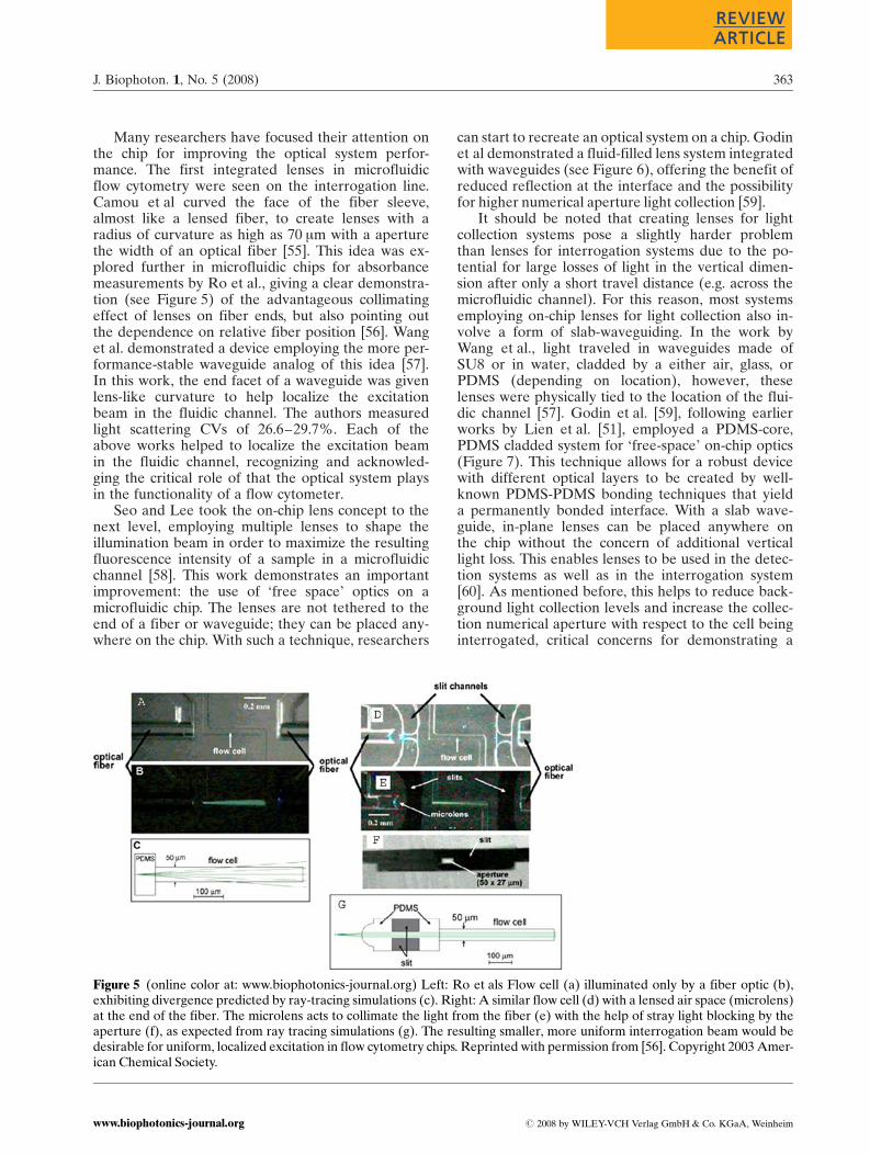
Many researchers have focused their attention onthe chip for improving the optical system perfor-mance. The first integrated lenses in microfluidicflow cytometry were seen on the interrogation line.Camou et al curved the face of the fiber sleeve,almost like a lensed fiber, to create lenses with aradius of curvature as high as 70 mm with a aperturethe width of an optical fiber [55]. This idea was ex-plored further in microfluidic chips for absorbancemeasurements by Ro et al., giving a clear demonstra-tion (see Figure 5) of the advantageous collimatingeffect of lenses on fiber ends, but also pointing outthe dependence on relative fiber position [56]. Wanget al. demonstrated a device employing the more per-formance-stable waveguide analog of this idea [57].In this work, the end facet of a waveguide was givenlens-like curvature to help localize the excitationbeam in the fluidic channel. The authors measuredlight scattering CVs of 26.6–29.7%. Each of theabove works helped to localize the excitation beamin the fluidic channel, recognizing and acknowled-ging the critical role of that the optical system playsin the functionality of a flow cytometer.
Seo and Lee took the on-chip lens concept to thenext level, employing multiple lenses to shape theillumination beam in order to maximize the resultingfluorescence intensity of a sample in a microfluidicchannel [58]. This work demonstrates an importantimprovement: the use of ‘free space’ optics on amicrofluidic chip. The lenses are not tethered to theend of a fiber or waveguide; they can be placed any-where on the chip. With such a technique, researchers
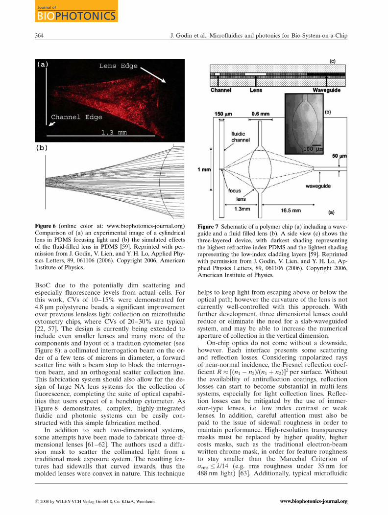
can start to recreate an optical system on a chip. Godinet al demonstrated a fluid-filled lens system integratedwith waveguides (see Figure 6), offering the benefit ofreduced reflection at the interface and the possibilityfor higher numerical aperture light collection [59].
It should be noted that creating lenses for lightcollection systems pose a slightly harder problemthan lenses for interrogation systems due to the po-tential for large losses of light in the vertical dimen-sion after only a short travel distance (e.g. across themicrofluidic channel). For this reason, most systemsemploying on-chip lenses for light collection also in-volve a form of slab-waveguiding. In the work byWang et al., light traveled in waveguides made ofSU8 or in water, cladded by a either air, glass, orPDMS (depending on location), however, theselenses were physically tied to the location of the flui-dic channel [57]. Godin et al. [59], following earlierworks by Lien et al. [51], employed a PDMS-core,PDMS cladded system for ‘free-space’ on-chip optics(Figure 7). This technique allows for a robust devicewith different optical layers to be created by well-known PDMS-PDMS bonding techniques that yielda permanently bonded interface. With a slab wave-guide, in-plane lenses can be placed anywhere onthe chip without the concern of additional verticallight loss. This enables lenses to be used in the detec-tion systems as well as in the interrogation system[60]. As mentioned before, this helps to reduce back-ground light collection levels and increase the collec-tion numerical aperture with respect to the cell beinginterrogated, critical concerns for demonstrating a
Figure 5 (online color at: www.biophotonics-journal.org) Left: Ro et als Flow cell (a) illuminated only by a fiber optic (b),exhibiting divergence predicted by ray-tracing simulations (c). Right: A similar flow cell (d) with a lensed air space (microlens)at the end of the fiber. The microlens acts to collimate the light from the fiber (e) with the help of stray light blocking by theaperture (f), as expected from ray tracing simulations (g). The resulting smaller, more uniform interrogation beam would bedesirable for uniform, localized excitation in flow cytometry chips. Reprinted with permission from [56]. Copyright 2003 Amer-ican Chemical Society.
J. Biophoton. 1, No. 5 (2008) 363
REVIEWREVIEWARTICLEARTICLE
# 2008 by WILEY-VCH Verlag GmbH & Co. KGaA, Weinheimwww.biophotonics-journal.org
BsoC due to the potentially dim scattering andespecially fluorescence levels from actual cells. Forthis work, CVs of 10–15% were demonstrated for4.8 mm polystyrene beads, a significant improvementover previous lensless light collection on microfluidiccytometry chips, where CVs of 20–30% are typical[22, 57]. The design is currently being extended toinclude even smaller lenses and many more of thecomponents and layout of a tradition cytometer (seeFigure 8): a collimated interrogation beam on the or-der of a few tens of microns in diameter, a forwardscatter line with a beam stop to block the interroga-tion beam, and an orthogonal scatter collection line.This fabrication system should also allow for the de-sign of large NA lens systems for the collection offluorescence, completing the suite of optical capabil-ities that users expect of a benchtop cytometer. AsFigure 8 demonstrates, complex, highly-integratedfluidic and photonic systems can be easily con-structed with this simple fabrication method.
In addition to such two-dimensional systems,some attempts have been made to fabricate three-di-mensional lenses [61–62]. The authors used a diffu-sion mask to scatter the collimated light from atraditional mask exposure system. The resulting fea-tures had sidewalls that curved inwards, thus themolded lenses were convex in nature. This technique
helps to keep light from escaping above or below theoptical path; however the curvature of the lens is notcurrently well-controlled with this approach. Withfurther development, three dimensional lenses couldreduce or eliminate the need for a slab-waveguidedsystem, and may be able to increase the numericalaperture of collection in the vertical dimension.
On-chip optics do not come without a downside,however. Each interface presents some scatteringand reflection losses. Considering unpolarized raysof near-normal incidence, the Fresnel reflection coef-ficient R � [(n1 � n2)/(n1 þ n2)]2 per surface. Withoutthe availability of antireflection coatings, reflectionlosses can start to become substantial in multi-lenssystems, especially for light collection lines. Reflec-tion losses can be mitigated by the use of immer-sion-type lenses, i.e. low index contrast or weaklenses. In addition, careful attention must also bepaid to the issue of sidewall roughness in order tomaintain performance. High-resolution transparencymasks must be replaced by higher quality, highercosts masks, such as the traditional electron-beamwritten chrome mask, in order for feature roughnessto stay smaller than the Marechal Criterion ofsrms � l/14 (e.g. rms roughness under 35 nm for488 nm light) [63]. Additionally, typical microfluidic
Figure 6 (online color at: www.biophotonics-journal.org)Comparison of (a) an experimental image of a cylindricallens in PDMS focusing light and (b) the simulated effectsof the fluid-filled lens in PDMS [59]. Reprinted with per-mission from J. Godin, V. Lien, and Y. H. Lo, Applied Phy-sics Letters, 89, 061106 (2006). Copyright 2006, AmericanInstitute of Physics.
Figure 7 Schematic of a polymer chip (a) including a wave-guide and a fluid filled lens (b). A side view (c) shows thethree-layered device, with darkest shading representingthe highest refractive index PDMS and the lightest shadingrepresenting the low-index cladding layers [59]. Reprintedwith permission from J. Godin, V. Lien, and Y. H. Lo, Ap-plied Physics Letters, 89, 061106 (2006). Copyright 2006,American Institute of Physics.
J. Godin et al.: Microfluidics and photonics for Bio-System-on-a-Chip364
Journal of
BIOPHOTONICS
# 2008 by WILEY-VCH Verlag GmbH & Co. KGaA, Weinheim www.biophotonics-journal.org

chip feature depths are quite large by microfa-brication standards (�50–100 mm), so maintainingsmooth, optical-quality sidewalls for this depth canpose quite a challenge. Seo et al. reported roughness�100 nm for their silicon mold sidewalls after aDRIE fabrication process. They were able to furtherreduce this roughness to 20 nm using a wet etchingprocess [64]. Molds created by SU8 polymer canhave sidewall roughness down to 25 nm or below aswell [65]. Careful attention must be paid to ensurethat sidewalls are not just smooth, but are also verti-cal and exhibit sharp corners. Rather than createphysically smooth sidewalls, the previously-men-tioned L2 lens mitigates the issue of surface rough-ness by using a continuous flow fluidic lens whoseshape is controlled by a sheathing fluid, which isindex-matched to the substrate [54]. This effectivelymasks the sidewall roughness, and the lens sidewallbecomes the much smoother fluid-fluid interface.
D. Beyond Lenses
A few groups have started to venture even a bitfurther than lenses, creating an even broader optical
toolbox that can further improve the performance ofmicrofluidic flow cytometry chips. Apertures havebeen demonstrated by filling PDMS channels withblack ink [54, 56]. Apertures and beam blocks playan important role in background and stray light re-duction in traditional flow cytometers, thus the abil-ity to implement these features in microfluidic flowcytometers will be an important step in attaining per-formance on par with the benchtop device [66].
Kou et al demonstrated prisms for beam steering[67]. Following the concept of spectral flow cyto-metry [68], the use of similar microfabricated prismsor perhaps gratings could be envisioned as thedispersive elements for the implementation of com-pact, multi-color detection systems. Integrated filtershave also been demonstrated in PDMS-based de-vices using dye-doped polymer to create absorptionfilters [46, 69]. Hoffman et al demonstrated Su-dan II-doped PDMS long pass filters with >80%transmission above 570 nm and <.01% transmissionbelow 500 nm [69]. They also note negligible auto-fluorescence, a very important consideration for fluor-escence detection devices. Bliss et al extended theidea of Sudan-doped PDMS to create ‘wavelength-se-lective’ waveguides: waveguides that absorb the illu-mination light while passing the excitation light.Transmission above 570 was high (near 100%), whiletransmission dropped to 3–11% for wavelengths be-low 500 nm. Tunable filters based on flow of absorb-ing fluids have been described as well [70].
Some researchers have taken integration even afew steps further, integrating lasers and detectorsonto the chips as well. Balsev et al. explored the pos-sibility of a fully-integrated chip: laser, fluidics, anddetectors all on a single silicon chip with SU8 fea-tures [71]. A number of researchers have demon-strated means of creating on-chip lasers [67, 72].Dye lasers in particular are favored in microfluidicsystems due to their materials system compatibility.These lasers offer the benefits of compactness, lowpower consumption, and wavelength tunability. Un-fortunately these lasers still require an optical pumpsource; however, diode lasers may be a good candi-date for a pumping source as they continue to be-come smaller and higher-powered.
Researchers have also been considering the wayin which data is collected in an attempt to improvethe acquired signal in microfluidic flow cytometry. Inparticular, if the sensitivity of the collected data canbe enhanced, researchers may be able to sacrificesome sensitivity (and thus cost or size) of the detec-tors; namely to switch from the use of PMTs tophotodiodes. Additionally, such sensitivity enhance-ments would be helpful even for the more sensitiveAPD-based detection systems to reach higher oper-ating standards, for example in low-intensity fluores-cence measurements. Lien et al exploited the abilityto readily create an array of waveguides in a micro-
Figure 8 (online color at: www.biophotonics-journal.org)Early prototype of a microfluidic cytometry chip includingwaveguides and lenses for an excitation source (EX), a for-ward scatter collection line (FS) including a beam stop(BS), a side scatter collection line (SS), a large-angle scat-ter collection line (LAS), and a line for fluorescence col-lection (FL) (unpublished). The seamless integration offluidic and photonic elements is accomplished by simplemicrofabrication techniques [60].
J. Biophoton. 1, No. 5 (2008) 365
REVIEWREVIEWARTICLEARTICLE
# 2008 by WILEY-VCH Verlag GmbH & Co. KGaA, Weinheimwww.biophotonics-journal.org
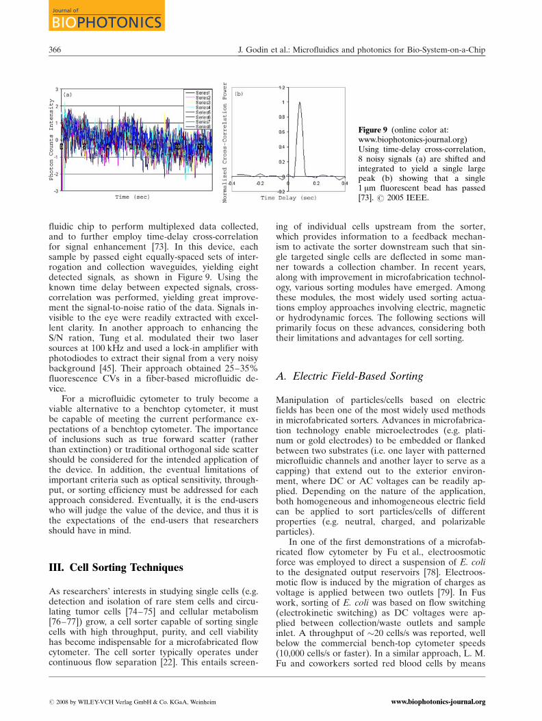
fluidic chip to perform multiplexed data collected,and to further employ time-delay cross-correlationfor signal enhancement [73]. In this device, eachsample by passed eight equally-spaced sets of inter-rogation and collection waveguides, yielding eightdetected signals, as shown in Figure 9. Using theknown time delay between expected signals, cross-correlation was performed, yielding great improve-ment the signal-to-noise ratio of the data. Signals in-visible to the eye were readily extracted with excel-lent clarity. In another approach to enhancing theS/N ration, Tung et al. modulated their two lasersources at 100 kHz and used a lock-in amplifier withphotodiodes to extract their signal from a very noisybackground [45]. Their approach obtained 25–35%fluorescence CVs in a fiber-based microfluidic de-vice.
For a microfluidic cytometer to truly become aviable alternative to a benchtop cytometer, it mustbe capable of meeting the current performance ex-pectations of a benchtop cytometer. The importanceof inclusions such as true forward scatter (ratherthan extinction) or traditional orthogonal side scattershould be considered for the intended application ofthe device. In addition, the eventual limitations ofimportant criteria such as optical sensitivity, through-put, or sorting efficiency must be addressed for eachapproach considered. Eventually, it is the end-userswho will judge the value of the device, and thus it isthe expectations of the end-users that researchersshould have in mind.
III. Cell Sorting Techniques
As researchers’ interests in studying single cells (e.g.detection and isolation of rare stem cells and circu-lating tumor cells [74–75] and cellular metabolism[76–77]) grow, a cell sorter capable of sorting singlecells with high throughput, purity, and cell viabilityhas become indispensable for a microfabricated flowcytometer. The cell sorter typically operates undercontinuous flow separation [22]. This entails screen-
ing of individual cells upstream from the sorter,which provides information to a feedback mechan-ism to activate the sorter downstream such that sin-gle targeted single cells are deflected in some man-ner towards a collection chamber. In recent years,along with improvement in microfabrication technol-ogy, various sorting modules have emerged. Amongthese modules, the most widely used sorting actua-tions employ approaches involving electric, magneticor hydrodynamic forces. The following sections willprimarily focus on these advances, considering boththeir limitations and advantages for cell sorting.
A. Electric Field-Based Sorting
Manipulation of particles/cells based on electricfields has been one of the most widely used methodsin microfabricated sorters. Advances in microfabrica-tion technology enable microelectrodes (e.g. plati-num or gold electrodes) to be embedded or flankedbetween two substrates (i.e. one layer with patternedmicrofluidic channels and another layer to serve as acapping) that extend out to the exterior environ-ment, where DC or AC voltages can be readily ap-plied. Depending on the nature of the application,both homogeneous and inhomogeneous electric fieldcan be applied to sort particles/cells of differentproperties (e.g. neutral, charged, and polarizableparticles).
In one of the first demonstrations of a microfab-ricated flow cytometer by Fu et al., electroosmoticforce was employed to direct a suspension of E. colito the designated output reservoirs [78]. Electroos-motic flow is induced by the migration of charges asvoltage is applied between two outlets [79]. In Fuswork, sorting of E. coli was based on flow switching(electrokinetic switching) as DC voltages were ap-plied between collection/waste outlets and sampleinlet. A throughput of �20 cells/s was reported, wellbelow the commercial bench-top cytometer speeds(10,000 cells/s or faster). In a similar approach, L. M.Fu and coworkers sorted red blood cells by means
Figure 9 (online color at:www.biophotonics-journal.org)Using time-delay cross-correlation,8 noisy signals (a) are shifted andintegrated to yield a single largepeak (b) showing that a single1 mm fluorescent bead has passed[73]. # 2005 IEEE.
J. Godin et al.: Microfluidics and photonics for Bio-System-on-a-Chip366
Journal of
BIOPHOTONICS
# 2008 by WILEY-VCH Verlag GmbH & Co. KGaA, Weinheim www.biophotonics-journal.org

of electrokinetic switching [80]. By changing the re-lative voltages applied to the outlet channels, thesorter can achieve three switching modes (shown inFigure 10), which provide the potential of sortingthree different particle/cell types in a given run. Inthis work, focusing and sorting have both beenachieved electrokinetically by applying DC electricfields, but the magnitude of the DC voltages neededranges from 300–500 V, which is impractically highdue to the high power consumption. Also, high elec-tric field not only can cause heating problems butalso inflict great damages to cells and thus, renderingcell viability significantly low after sorting. Anotherelectroosmosis-based sorter, requiring a significantlylower input voltage (e.g. 40 V), was demonstrated byDittrich and Schwille [81]. This system incorporatedan electrokinetic-driven flow channel oriented per-pendicular to the sample channel. As a hydrodyna-
mically-driven particle enters the Y sorting junction,activation of a perpendicular electroosmotic flow willdeflect particle to either side of the output channels(depending on the polarity of the input voltage).Though different colored fluorescent beads could besorted, the reported throughput was between 0.3–1beads/sec, limited by the activation time of the electro-des for inducing the electroosmotic deflection flow. Insummary, electroosmosis-based sorters are relativelyeasy to fabricate (insertion of Pt electrode into the in-let/outlet reservoirs) and the operation is relativelystraightforward, but they suffer from some commondrawbacks including frequent change of voltage set-tings due to ion depletion [82], electrolysis-inducedbubbles at the electrodes surface, low throughput andpotentially low cell viability, and high power consump-tion (e.g. the use of high DC voltages).
Sorting based on dielectrophoresis (DEP) hasalso become very popular over the years, as theapproach can alleviate some of the major limitationsencountered by the electroosmosis-based methodssuch as high power usage, low throughput, and re-duced cell viability. Rather than the uniform electricfield produced in electroosmosis, DEP exposesparticles/cells to a nonuniform electric field by apply-ing AC voltages in ultrasonic regime (i.e. MHz) tothe fluid-immersed electrodes. The dielectrophoreticforce experienced by the particle within the field canbe described by the following equations [83]:
F ¼ 2pa3e1 Re ðfCMðwÞÞ grad ðE2Þ (1)
where a is the radius of the particle, el is the per-mittivity of the suspending medium, w is the an-gular frequency and Re (fCM(w)) is the real part ofthe dipolar Clausius-Mossotti (CM) factor (i.e.�0.5 < fCM(w) < 1), where:
fCMðwÞ ¼s*p � s*ls*p þ s*l
(2)
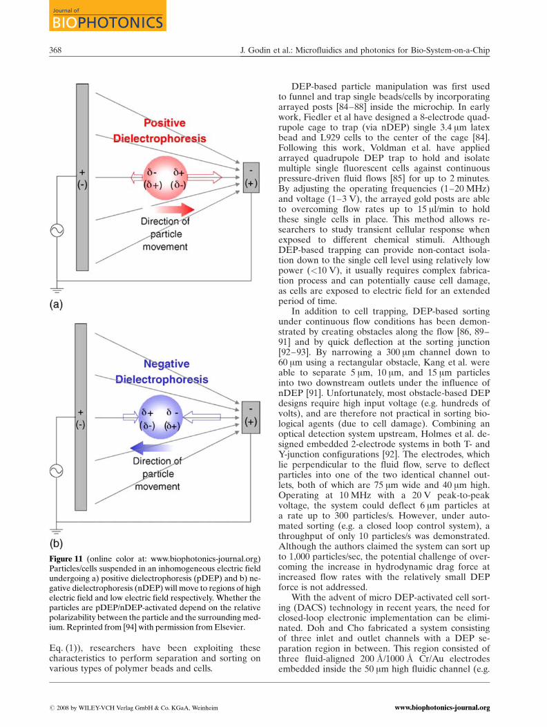
Here e*p and e*1 are complex permittivities of the par-ticle and the surrounding solvent, respectively. Whenparticles/cells experience electric field, they becomepolarized. Due to the relative polarizability betweenthe solvent and the particle, there is a net movementof particles/cells toward either the high or low elec-tric field locations, depending on the polarizability(see Figure 11). Positive dielectrophoresis (pDEP)occurs when the polarizability of the particles is lar-ger than the polarizability of the surrounding fluid(i.e. fCM(w) > 0). In this case, particles are attractedto the high electric field region. In contrast, when thesolvents polarizability is greater than the particles po-larizability, negative dielectrophoresis (nDEP) comesinto play, causing particles to migrate toward the lowelectric field region. Since the magnitude of theDEP force is highly dependent on both the size andthe polarizability of the particles/cells (refer to
Figure 10 (online color at: www.biophotonics-journal.org)a) Electric potential contour at 2 : 1 focusing ratio (e.g. ra-tio of voltage applied to focusing channel to sample chan-nel). b) and c) show the numerical simulation and experi-mental results of the flow switching phenomena.Reprinted from [80] with permission from Elsevier.
J. Biophoton. 1, No. 5 (2008) 367
REVIEWREVIEWARTICLEARTICLE
# 2008 by WILEY-VCH Verlag GmbH & Co. KGaA, Weinheimwww.biophotonics-journal.org
Eq. (1)), researchers have been exploiting thesecharacteristics to perform separation and sorting onvarious types of polymer beads and cells.
DEP-based particle manipulation was first usedto funnel and trap single beads/cells by incorporatingarrayed posts [84–88] inside the microchip. In earlywork, Fiedler et al have designed a 8-electrode quad-rupole cage to trap (via nDEP) single 3.4 mm latexbead and L929 cells to the center of the cage [84].Following this work, Voldman et al. have appliedarrayed quadrupole DEP trap to hold and isolatemultiple single fluorescent cells against continuouspressure-driven fluid flows [85] for up to 2 minutes.By adjusting the operating frequencies (1–20 MHz)and voltage (1–3 V), the arrayed gold posts are ableto overcoming flow rates up to 15 ml/min to holdthese single cells in place. This method allows re-searchers to study transient cellular response whenexposed to different chemical stimuli. AlthoughDEP-based trapping can provide non-contact isola-tion down to the single cell level using relatively lowpower (<10 V), it usually requires complex fabrica-tion process and can potentially cause cell damage,as cells are exposed to electric field for an extendedperiod of time.
In addition to cell trapping, DEP-based sortingunder continuous flow conditions has been demon-strated by creating obstacles along the flow [86, 89–91] and by quick deflection at the sorting junction[92–93]. By narrowing a 300 mm channel down to60 mm using a rectangular obstacle, Kang et al. wereable to separate 5 mm, 10 mm, and 15 mm particlesinto two downstream outlets under the influence ofnDEP [91]. Unfortunately, most obstacle-based DEPdesigns require high input voltage (e.g. hundreds ofvolts), and are therefore not practical in sorting bio-logical agents (due to cell damage). Combining anoptical detection system upstream, Holmes et al. de-signed embedded 2-electrode systems in both T- andY-junction configurations [92]. The electrodes, whichlie perpendicular to the fluid flow, serve to deflectparticles into one of the two identical channel out-lets, both of which are 75 mm wide and 40 mm high.Operating at 10 MHz with a 20 V peak-to-peakvoltage, the system could deflect 6 mm particles ata rate up to 300 particles/s. However, under auto-mated sorting (e.g. a closed loop control system), athroughput of only 10 particles/s was demonstrated.Although the authors claimed the system can sort upto 1,000 particles/sec, the potential challenge of over-coming the increase in hydrodynamic drag force atincreased flow rates with the relatively small DEPforce is not addressed.
With the advent of micro DEP-activated cell sort-ing (DACS) technology in recent years, the need forclosed-loop electronic implementation can be elimi-nated. Doh and Cho fabricated a system consistingof three inlet and outlet channels with a DEP se-paration region in between. This region consisted ofthree fluid-aligned 200 �A/1000 �A Cr/Au electrodesembedded inside the 50 mm high fluidic channel (e.g.
Figure 11 (online color at: www.biophotonics-journal.org)Particles/cells suspended in an inhomogeneous electric fieldundergoing a) positive dielectrophoresis (pDEP) and b) ne-gative dielectrophoresis (nDEP) will move to regions of highelectric field and low electric field respectively. Whether theparticles are pDEP/nDEP-activated depend on the relativepolarizability between the particle and the surrounding med-ium. Reprinted from [94] with permission from Elsevier.
J. Godin et al.: Microfluidics and photonics for Bio-System-on-a-Chip368
Journal of
BIOPHOTONICS
# 2008 by WILEY-VCH Verlag GmbH & Co. KGaA, Weinheim www.biophotonics-journal.org

in direct contact with fluid) [94]. The design is imple-mented for separating a mixture of viable and nonvi-able yeast cells in hydrodynamically-driven continu-ous flow. Since viable and nonviable yeast cellsdemonstrate a different dielectrophoretic response(i.e. either nDEP or pDEP, respectively) at differentelectric field frequencies and medium conductivities,the authors were able to separate viable yeast cellsfrom nonviable yeast cells (see Figure 12) at a max-imum throughput of 1300 cells/sec with 97% purityin the viable fraction and 70% in the nonviable frac-tion. Under 5 MHz frequency in a 5 mS/cm fluid med-ium, viable/nonviable cells which experience pDEP/nDEP would move to a area of high/low electric field,resulting in spatial separation as the cells approachexit channels. Similarly, by placing 200 nm arrayedplatinum electrodes perpendicular to the fluidic flow,Braschler et al. have also separated viable and nonvi-able cells with a purity of nearly 100% [95]. In addi-tion, the authors have also enriched red blood cellsinfected with B. bovis from a 7% infected mixture toa 50% infected mixture. The inability to obtain higherpurity is due to high variability of dielectric proper-ties for non-infected blood cells.
By conjugating polystyrene beads to rare bacteriathat express specific surface markers, Xiaoyuan Huet al. were able to amplify the difference in DEP re-sponse between targeted and non-targeted bacteriafor DACS [96]. The 300 nm Au electrodes serving todeflect cells under nDEP are situated at an angle of15� relative to the direction of the flow. As bead-la-beled bacteria encounter the electrode, the nDEPforce (�388 pN) experienced by the bacteria willovercome the hydrodynamic drag force (�368 pN),resulting in sorting of targeted cells into the collec-
tion channel (Figure 13). Using this method, theauthors achieved a throughput of 104 cell/s, �95%recovery, and 250-fold enrichment after 2 roundsof DACS. This is the first DEP sorter exhibitingthroughput comparable to a bench-top FACS. In theauthors most recent work, they developed a two-stage DACS to screen E coli cells that display pep-tides which bind to antibody from a library of5 � 108 different clones at a throughput of >108
Figure 12 (online color at:www.biophotonics-journal.org)Bands of yeast cell aggregationsunder 8 Vp-p at sinusoidal fre-quencies of a) 10 kHz and b)5 MHz for viable yeast cells and c)10 kHz and d) 5 MHz for nonvi-able yeast cells. The bright anddark regions are electrodes andglass substrate respectively, andthe cells are immersed in a 5 mS/cm buffer fluid. Reprinted from[94] with permission from Elsevier.
Figure 13 Sorting mechanism for the DACS. A) Bead-la-beled cells experience significantly higher nDEP forcethan non-labeled cells and therefore, can overcome hydro-dynamic drag forces resulting in transversal movementdown to the collection channel. B) Schematic view ofangled electrodes, inlet channels (e.g. buffer fluid sand-wiched by two sample channels), and outlet collection andwaste channels [96].
J. Biophoton. 1, No. 5 (2008) 369
REVIEWREVIEWARTICLEARTICLE
# 2008 by WILEY-VCH Verlag GmbH & Co. KGaA, Weinheimwww.biophotonics-journal.org
cells/h [97]. The method requires additional bead-la-beling process (yield was not reported) and maycause cell damage due to prolonged electric field ex-posure, it does provide a continuous, contactless, low-powered, DEP-activated separation with high purityand throughput comparable to commercial FACS.
B. Magnetic Sorting
Magnetic cell sorting via on-chip devices has re-ceived relatively little attention. Cell sorting by ap-plying magnetic field has been tried by some re-search groups. In magnetic sorting, cells of interestare labeled with magnetic beads first and they areseparated from the sample flow by magnetic field.Magnetic labeling of biological cells or particles withmagnetic nanoparticles is performed by attachingmagnetic particles to the cell surface [98] or by intro-ducing them into the cell [99].
It is reported that paramagnetic beads can forman immuno-capture ‘bed’ in order to isolate rare cellsfrom blood. Some groups have utilized magneticbeads in microfluidics devices for chemical and biolo-gical reactions. Those magnetic beads beds were suc-cessfully applied to dynamic DNA hybridization[100] and mRNA isolation [101] within a microflui-dics devices. The sample particles were stopped in la-minar flow by an external magnetic field and the re-action was performed on the particle bed.
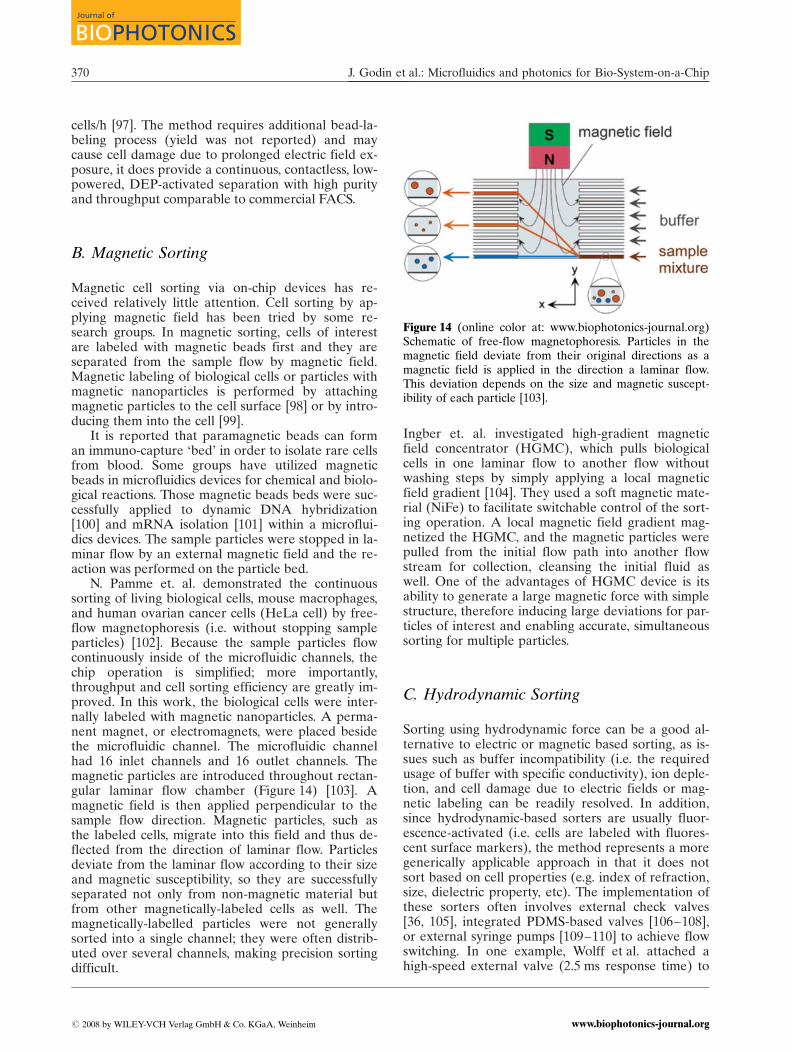
N. Pamme et. al. demonstrated the continuoussorting of living biological cells, mouse macrophages,and human ovarian cancer cells (HeLa cell) by free-flow magnetophoresis (i.e. without stopping sampleparticles) [102]. Because the sample particles flowcontinuously inside of the microfluidic channels, thechip operation is simplified; more importantly,throughput and cell sorting efficiency are greatly im-proved. In this work, the biological cells were inter-nally labeled with magnetic nanoparticles. A perma-nent magnet, or electromagnets, were placed besidethe microfluidic channel. The microfluidic channelhad 16 inlet channels and 16 outlet channels. Themagnetic particles are introduced throughout rectan-gular laminar flow chamber (Figure 14) [103]. Amagnetic field is then applied perpendicular to thesample flow direction. Magnetic particles, such asthe labeled cells, migrate into this field and thus de-flected from the direction of laminar flow. Particlesdeviate from the laminar flow according to their sizeand magnetic susceptibility, so they are successfullyseparated not only from non-magnetic material butfrom other magnetically-labeled cells as well. Themagnetically-labelled particles were not generallysorted into a single channel; they were often distrib-uted over several channels, making precision sortingdifficult.
Ingber et. al. investigated high-gradient magneticfield concentrator (HGMC), which pulls biologicalcells in one laminar flow to another flow withoutwashing steps by simply applying a local magneticfield gradient [104]. They used a soft magnetic mate-rial (NiFe) to facilitate switchable control of the sort-ing operation. A local magnetic field gradient mag-netized the HGMC, and the magnetic particles werepulled from the initial flow path into another flowstream for collection, cleansing the initial fluid aswell. One of the advantages of HGMC device is itsability to generate a large magnetic force with simplestructure, therefore inducing large deviations for par-ticles of interest and enabling accurate, simultaneoussorting for multiple particles.
C. Hydrodynamic Sorting
Sorting using hydrodynamic force can be a good al-ternative to electric or magnetic based sorting, as is-sues such as buffer incompatibility (i.e. the requiredusage of buffer with specific conductivity), ion deple-tion, and cell damage due to electric fields or mag-netic labeling can be readily resolved. In addition,since hydrodynamic-based sorters are usually fluor-escence-activated (i.e. cells are labeled with fluores-cent surface markers), the method represents a moregenerically applicable approach in that it does notsort based on cell properties (e.g. index of refraction,size, dielectric property, etc). The implementation ofthese sorters often involves external check valves[36, 105], integrated PDMS-based valves [106–108],or external syringe pumps [109–110] to achieve flowswitching. In one example, Wolff et al. attached ahigh-speed external valve (2.5 ms response time) to
Figure 14 (online color at: www.biophotonics-journal.org)Schematic of free-flow magnetophoresis. Particles in themagnetic field deviate from their original directions as amagnetic field is applied in the direction a laminar flow.This deviation depends on the size and magnetic suscept-ibility of each particle [103].
J. Godin et al.: Microfluidics and photonics for Bio-System-on-a-Chip370
Journal of
BIOPHOTONICS
# 2008 by WILEY-VCH Verlag GmbH & Co. KGaA, Weinheim www.biophotonics-journal.org

the collection outlet to sort rare fluorescent beadsfrom chicken red blood cells (Figure 15). A through-put of 12,000 cells/s (comparable to bench-top flowcytometer) and an enrichment of 100-fold were re-ported, though the purity of the sorted sample is low[36] (i.e. nontargeted cells are collected along with
Figure 15 (online color at: www.biophotonics-journal.org)Schematics of high-throughput mFACS. Activation of exter-nal collection valve (i.e. triggered by upstream fluorescentdetection signal) draws out a fixed fluid volume, which con-tains the targeted cells, into the collection channel [36]. Re-produced by permission of The Royal Society of Chemistry.
Figure 16 (online color at: www.biophotonics-journal.org)Working principle of the piezoelectric (PZT) actuation-based sorter. The particles/cells are deflected down to thecollection channels (left or right channels) as PZT actuatorbends upward/downward. The transverse movement ofparticles is caused by the drag force of the fluid displacedby the PZT actuator as it bends (unpublished).
Figure 17 Images showing the flow-switching capabilitiesof the PZT-based sorter. The flow stream (Rhodamine6G) switches (a) to the left and (c) to the right as PZTactuator becomes positively (e.g. downward bending) andnegatively biased (e.g. upward bending), respectively. Dur-ing the non-ramping state (i.e. the actuation-off state), theflow stream returns (b) to the central region and exitsdown to the waste channel (unpublished).
J. Biophoton. 1, No. 5 (2008) 371
REVIEWREVIEWARTICLEARTICLE
# 2008 by WILEY-VCH Verlag GmbH & Co. KGaA, Weinheimwww.biophotonics-journal.org
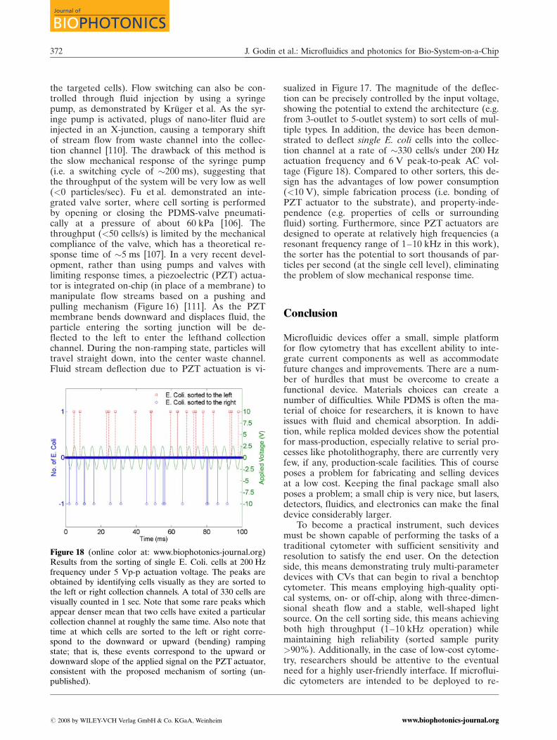
the targeted cells). Flow switching can also be con-trolled through fluid injection by using a syringepump, as demonstrated by Kruger et al. As the syr-inge pump is activated, plugs of nano-liter fluid areinjected in an X-junction, causing a temporary shiftof stream flow from waste channel into the collec-tion channel [110]. The drawback of this method isthe slow mechanical response of the syringe pump(i.e. a switching cycle of �200 ms), suggesting thatthe throughput of the system will be very low as well(<0 particles/sec). Fu et al. demonstrated an inte-grated valve sorter, where cell sorting is performedby opening or closing the PDMS-valve pneumati-cally at a pressure of about 60 kPa [106]. Thethroughput (<50 cells/s) is limited by the mechanicalcompliance of the valve, which has a theoretical re-sponse time of �5 ms [107]. In a very recent devel-opment, rather than using pumps and valves withlimiting response times, a piezoelectric (PZT) actua-tor is integrated on-chip (in place of a membrane) tomanipulate flow streams based on a pushing andpulling mechanism (Figure 16) [111]. As the PZTmembrane bends downward and displaces fluid, theparticle entering the sorting junction will be de-flected to the left to enter the lefthand collectionchannel. During the non-ramping state, particles willtravel straight down, into the center waste channel.Fluid stream deflection due to PZT actuation is vi-
sualized in Figure 17. The magnitude of the deflec-tion can be precisely controlled by the input voltage,showing the potential to extend the architecture (e.g.from 3-outlet to 5-outlet system) to sort cells of mul-tiple types. In addition, the device has been demon-strated to deflect single E. coli cells into the collec-tion channel at a rate of �330 cells/s under 200 Hzactuation frequency and 6 V peak-to-peak AC vol-tage (Figure 18). Compared to other sorters, this de-sign has the advantages of low power consumption(<10 V), simple fabrication process (i.e. bonding ofPZT actuator to the substrate), and property-inde-pendence (e.g. properties of cells or surroundingfluid) sorting. Furthermore, since PZT actuators aredesigned to operate at relatively high frequencies (aresonant frequency range of 1–10 kHz in this work),the sorter has the potential to sort thousands of par-ticles per second (at the single cell level), eliminatingthe problem of slow mechanical response time.
Conclusion
Microfluidic devices offer a small, simple platformfor flow cytometry that has excellent ability to inte-grate current components as well as accommodatefuture changes and improvements. There are a num-ber of hurdles that must be overcome to create afunctional device. Materials choices can create anumber of difficulties. While PDMS is often the ma-terial of choice for researchers, it is known to haveissues with fluid and chemical absorption. In addi-tion, while replica molded devices show the potentialfor mass-production, especially relative to serial pro-cesses like photolithography, there are currently veryfew, if any, production-scale facilities. This of courseposes a problem for fabricating and selling devicesat a low cost. Keeping the final package small alsoposes a problem; a small chip is very nice, but lasers,detectors, fluidics, and electronics can make the finaldevice considerably larger.
To become a practical instrument, such devicesmust be shown capable of performing the tasks of atraditional cytometer with sufficient sensitivity andresolution to satisfy the end user. On the detectionside, this means demonstrating truly multi-parameterdevices with CVs that can begin to rival a benchtopcytometer. This means employing high-quality opti-cal systems, on- or off-chip, along with three-dimen-sional sheath flow and a stable, well-shaped lightsource. On the cell sorting side, this means achievingboth high throughput (1–10 kHz operation) whilemaintaining high reliability (sorted sample purity>90%). Additionally, in the case of low-cost cytome-try, researchers should be attentive to the eventualneed for a highly user-friendly interface. If microflui-dic cytometers are intended to be deployed to re-
Figure 18 (online color at: www.biophotonics-journal.org)Results from the sorting of single E. Coli. cells at 200 Hzfrequency under 5 Vp-p actuation voltage. The peaks areobtained by identifying cells visually as they are sorted tothe left or right collection channels. A total of 330 cells arevisually counted in 1 sec. Note that some rare peaks whichappear denser mean that two cells have exited a particularcollection channel at roughly the same time. Also note thattime at which cells are sorted to the left or right corre-spond to the downward or upward (bending) rampingstate; that is, these events correspond to the upward ordownward slope of the applied signal on the PZT actuator,consistent with the proposed mechanism of sorting (un-published).
J. Godin et al.: Microfluidics and photonics for Bio-System-on-a-Chip372
Journal of
BIOPHOTONICS
# 2008 by WILEY-VCH Verlag GmbH & Co. KGaA, Weinheim www.biophotonics-journal.org

mote, resource-poor settings or purchased by indivi-dual research laboratories, the machines will need tobe easy to operate, requiring minimal training. Theymust, therefore, exhibit reliable and consistent per-formance; for example, not requiring changes in op-erating conditions for sorting different sample types.Additionally, the benefits and drawbacks of integra-tion must be considered each time a component isadded to the chip. The added cost of the component,such as an on-chip laser or filter, may or may not beworthwhile to the end user, and further may affectthe consistency of performance from chip to chip.Tradeoffs in sensitivity and resolution must also beconsidered for the application in mind.
The development of a microfluidic flow cyt-ometer may be the advance that brings a cytometerto every research lab, allowing for faster discoveryand understanding in areas such as cancer research,drug development, and genetics. Low cost, portabledevices could allow for HIV monitoring in remoteareas of Africa and Asia, helping antiretroviral drugsmake their way to patients in need. Low cost micro-fluidic devices could further help patients in affluentcountries to receive faster test results, and may re-duce the amount of blood needed for testing. Micro-fluidic cytometry chips could eventually integrate re-agent mixing stages for rapid, reliable labeling, orcell culture stages for bacterial and fungal studies.For the same reasons that microfluidic photonic de-vices could revolutionize cytometry, these same tech-nologies hold great promise to revolutionize thefields of biology, chemistry, and medicine. Individualcells or small-volume reactions could be studied inentirely new and detailed ways using small, portabledevices affordable to any researcher in any location.The technologies are emerging to create a new classof equipment that holds the potential to be cost ef-fective, portable and massively parallelized. Thesetechnologies must be fine-tuned and developed to-wards meaningful applications, looking both towardsimproving upon todays devices and also towardsfinding new technologies to which the integration ofmicrofluidics and photonics can be applied.
Jessica Godin received herB.S. degree in Applied &Engineering Physics fromCornell University in Ithaca,NY in 2004. She received anMS in Applied Physics fromthe University of California,San Diego in 2006, whereshe is now pursuing herPh.D. in the department of
Electrical and Computer Engineering. Currently, she isdeveloping an on-chip optical system for compact flowcytometry and other lab-on-a-chip devices. Her re-search interests include flow cytometry and othermeans of single-cell analysis, as well as general optoflui-dic devices.
Chun H. Chen has receivedB.S. degree from Universityof California, Berkeley in2003. Currently, he is study-ing his Ph.D. at Universityof California, San Diego, inthe bioengineering depart-ment. For his current re-search, he is working on de-veloping a high-throughput
microfluidic sorter using piezoelectric-based technologythat can be applied to cancer diagnostics, genetic studyof rare bacterial cells, and isolation of stem cells.
Sung Hwan Cho receivedthe B.S degree in MaterialsScience and Engineeringfrom Seoul National Univer-sity, Seoul, Korea, in 2004and received the M.S degreein Materials Science andEngineering, in 2006, fromUniversity of California SanDiego, La Jolla, USA, where
he is currently working toward his Ph.D. degree. Hejoined Professor Yu-Hwa Los research group in 2006and has been working on microfluidic lab-on-a-chipsorting devices and polymer lenses. He is also inter-ested in designing an integrated opto-fluidic system ona polymer-based chip.
Wen Qiao was born in Nan-chang, China, in 1984. Shereceived her B. Sc. Degreein Optics from TianjinUniversity, China, in 2005.Then she became Ph.D. can-didate at Zhejiang Univer-sity, China. She is now doingdoctoral work at Universityof California, San Diego asa visiting scholar. Her cur-
rent research interests include fluidic lenses, super-human vision, and microfluidic devices.
J. Biophoton. 1, No. 5 (2008) 373
REVIEWREVIEWARTICLEARTICLE
# 2008 by WILEY-VCH Verlag GmbH & Co. KGaA, Weinheimwww.biophotonics-journal.org
References
[1] H. Chen and J. C. Meiners, Applied Physics Letters84, 2193 (2004).
[2] D. J. Beebe, G. A. Mensing, and G. M. Walker, An-nual Review of Biomedical Engineering 4, 261 (2002).
[3] A. Groisman, M. Enzelberger, and S. R. Quake, Mi-crofluidic Memory and Control Devices, vol. 300:American Association for the Advancement ofScience, 2003, pp. 955.
[4] J. P. Urbanski, W. Thies, C. Rhodes, S. Amarasinghe,and T. Thorsen, Lab on a Chip 6, 96 (2006).
[5] M. Prakash and N. Gershenfeld, Science 315, 832(2007).
[6] N. Gleichmann, D. Malsch, M. Kielpinski, W. Ros-sak, G. Mayer, and T. Henkel, Chemical EngineeringJournal 135, 210 (2008).
[7] I. Inoue, Y. Wakamoto, H. Moriguchi, K. Okano,and K. Yasuda, Lab on a Chip 1, 50 (2001).
[8] C. L. Hansen, E. Skordalakes, J. M. Berger, andS. R. Quake, Proceedings of the National Academy
of Sciences of the United States of America 99,16531 (2002).
[9] C. D. Chin, V. Linder, and S. K. Sia, Lab on a Chip7, 41 (2007).
[10] D. Psaltis, S. R. Quake, and C. Yang, Nature 442,381 (2006).
[11] R. L. Ewing and H. S. Abdel-Aty-Zohdy, Proceed-ings of the 2003 International Conference on Micro-electronics Systems Education, (2003).
[12] H. M. Shapiro, Practical flow cytometry, 4th ed.,(Wiley-Liss New York, Hoboken, NY, 2003).
[13] A. L. Givan, Flow Cytometry: First Principles, 2nded., (Wiley-Liss, Inc., New York, 2001).
[14] W. G. Telford, in “Small Lasers in Flow Cytometry,”in Methods in Molecular Biology: Flow CytometryProtocols, T. S. H. a. R. G. Hawley, 2nd. Totowa, NJ:Humana Press Inc, 2004.
[15] D. Sobek, A. M. Young, M. L. Gray, and S. D. Sen-turia, Proceedings of Micro Electro Mechanical Sys-tems, 1993, pp. 219.
[16] E. Altendorf, D. Zebert, M. Holl, and P. A. Yager,International Conference on Solid State Sensors andActuators, Chicago, 1997, pp. 531.
[17] Y. Xia and G. M. Whitesides, Angewandte ChemieInternational Edition 37, 550 (1998).
[18] M. A. Unger, H.-P. Chou, T. Thorsen, A. Scherer,and S. R. Quake, Science 288, 113 (2000).
[19] M. L. Chabinyc, D. T. Chiu, J. C. McDonald,A. D. Stroock, J. F. Christian, A. M. Karger, andG. M. Whitesides, Anal. Chem. 73, 4491 (2001).
[20] K. Haubert, T. Drier, and D. Beebe, Lab on a Chip6, 1548 (2006).
[21] G.-B. Lee, B.-H. Hwei, and G.-R. Huang, Journal ofMicromechanics and Microengineering 11, 654(2001).
[22] N. Pamme, R. Koyama, and A. Manz, Lab on a Chip3, 187 (2003).
[23] C. H. Lin and G. B. Lee, Journal of Micromechanicsand Microengineering 13, 447 (2003).
[24] P. K. Wong, Y.-K. Lee, and C.-M. Ho, Journal ofFluid Mechanics 497, 55 (2003).
[25] J. B. Knight, A. Vishwanath, J. P. Brody, andR. H. Austin, Physical Review Letters 80, 3863(1998).
[26] G.-B. Lee, C.-I. Hung, B.-J. Ke, G.-R. Huang, B.-H.Hwei, and H.-F. Lai, Transactions of the ASME 123,672 (2001).
[27] G.-B. Lee, C.-C. Chang, S.-B. Huang, and R.-J. Yang,Journal of Micromechanics and Microengineering16, 1024 (2006).
[28] D. Huh, Y.-C. Tung, H.-H. Wei, J. B. Grotherg,S. J. Skerlos, K. Kurabayashi, and S. Takayama, Bio-medical Microdevices 4, 141 (2002).
[29] T. Stiles, R. Fallon, T. Vestad, J. Oakey,D. W. M. Marr, J. Squier, and R. Jimenez, MicrofluidNanofluid 1, 280 (2005).
[30] D. P. Schrum, C. T. Culbertson, S. C. Jacobson, andJ. M. Ramsey, Anal. Chem 71, 4173 (1999).
[31] H.-P. Chou, C. Spence, A. Scherer, and S. Quake,Proc. Natl. Acad. Sci USA 96, 11 (1999).
Frank Tsai is currently pursu-ing his Ph.D. degree in Uni-versity of California, SanDiego (UCSD). He receivedhis BS and MS degree inElectrical Engineering fromNational Chiao-Tung Univer-sity, Hsinchu, Taiwan, in 1999and 2001respectively. From2001 to 2005, he worked asan engineer in Computer andCommunication Research
Laboratory, Industrial Technology Research Institute,Hsinchu, Taiwan. His current research interests includemicrofluidics and bio-inspired fluidic lens.
Yuhwa Lo received hisPh.D. in electrical engineer-ing from UC Berkeley in1987. He worked at Bellcore(Telcordia) as a technicalstaff member from 1988–1990, and became an assis-tant and then associate pro-fessor of Cornell Universityfrom 1991 to 1999. He be-came a professor of UCSDin 1999 and has been the di-
rector of the Nano3 Facility (Nanoscience, Nanoengi-neering, and Nanomedicine) since 2005. Currently hisresearch interests are in bio-imaging, bio-sensing, nano-photonics, and single-photon detectors. He has morethan 300 publications and been granted 16 patents. Heis a fellow of the Optical Society of America and theIEEE.
J. Godin et al.: Microfluidics and photonics for Bio-System-on-a-Chip374
Journal of
BIOPHOTONICS
# 2008 by WILEY-VCH Verlag GmbH & Co. KGaA, Weinheim www.biophotonics-journal.org

[32] L.-M. Fu, R.-J. Yang, and G.-B. Lee, Anal. Chem 75,1905 (2003).
[33] G.-B. Lee, L.-M. Fu, R.-J. Yang, Y.-J. Pan, and C.-H.Lin, The 12th International Conference on SolidState Sensors, Actuators and Microsystems, Boston,2003, pp. 1895.
[34] H. Morgan, D. Holmes, and N. G. Green, IEE Proc.-Nanobiotechnol 150, 76 (2003).
[35] C.-H. Lin, G.-B. Lee, L.-M. Fu, and B.-H. Hwey,Journal of microelectromechanical systems 13, 923(2004).
[36] A. Wolff, I. R. Perch-Nielsen, U. D. Larsen, P. Friis,G. Goranovic, C. R. Poulsen, J. P. Kutter, and P.Telleman, Lab on a Chip 3, 22 (2003).
[37] H. Klank, G. Goranovic, J. P. Kutter, H. Gjelstrup,J. Michelsen, and C. H. Westergaard, Journal ofMicromechanics and Microengineering 12, 862(2002).
[38] C.-C. Chang, Z.-X. Huang, and R.-J. Yang, Journalof Micromechanics and Microengineering 17, (2007).
[39] C. Simonnet and A. Groisman, Applied Physics Let-ters 87, 114104 (2005).
[40] R. Yang, D. L. Feeback, and W. Wanga, Sensors andActuators A 118, 259 (2005).
[41] N. Sundararajan, M. S. Pio, L. P. Lee, and A. A. Ber-lin, Journal of Microelectromechanical systems 13,559 (2004).
[42] X. Mao, J. R. Waldeisen, and T. J. Huang, Lab On aChip 7, 1260 (2007).
[43] J. Kruger, K. Singh, A. ONeill, C. Jackson, A. Morri-son, and P. OBrien, Journal of Micromechanics andMicroengineering 12, 486 (2002).
[44] S. Kostner and M. J. Vellekoop, Sensors & Actua-tors: B. Chemical (2007).
[45] Y.-C. Tung, M. Zhang, C.-T. Lin, K. Kurabayashi,and S. J. Skerlos, Sensors and Actuators B: Chemical98, 356 (2004).
[46] C. L. Bliss, J. N. McMullin, and C. J. Backhouse, Labon a Chip 7, 1280 (2007).
[47] K. B. Mogensen, N. J. Petersen, J. Hubner, andJ. P. Kutter, Electrophoresis 22, 3930 (2001).
[48] J. N. McMullin, H. Qiao, S. Goel, C. L. Ren, andD. Li, Journal of Micromechanics and Microengi-neering 15, 1810 (2005).
[49] D. Spicer, J. N. McMullin, and H. Rourke, Journal ofMicromechanics and Microengineering 16, 1674(2006).
[50] S. H. Huang and F. G. Tseng, Journal of Microme-chanics and Microengineering 15, 2235 (2005).
[51] V. Lien, H. Lin, J. Chuang, M. J. Sailor, and Y. H.Lo, Engineering in Medicine and Biology Society,2004. EMBC 2004. Conference Proceedings. 26thAnnual International Conference of the 1 (2004).
[52] V. Lien, Y. Berdichevsky, Y. H. Lo, J. Khandurina,and A. Guttman, Lasers and Electro-Optics, 2003.CLEO03. Conference on, 4 (2003).
[53] D. B. Wolfe, R. S. Conroy, P. Garstecki, B. T. Mayers,M. A. Fischbach, K. E. Paul, M. Prentiss, andG. M. Whitesides, Proceedings of the National Acad-emy of Sciences 101, 12434 (2004).
[54] S. K. Y. Tang, C. A. Stan, and G. M. Whitesides, Labon a Chip 8, 395 (2008).
[55] S. Camou, H. Fujita, and T. Fujii, Lab on a Chip 3,40 (2003).
[56] K. W. Ro, K. Lim, B. C. Shim, and J. H. Hahn, Anal.Chem 77, 5160 (2005).
[57] Z. Wang, J. El-Ali, M. Engelund, T. Gotsæd,I. R. Perch-Nielsen, K. B. Mogensen, D. Snakenborg,J. P. Kutter, and A. Wolff, Lab on a Chip 4, 372 (2004).
[58] J. Seo and L. P. Lee, Sensors & Actuators: B. Chemi-cal 99, 615 (2004).
[59] J. Godin, V. Lien, and Y. H. Lo, Applied PhysicsLetters 89, 061106 (2006).
[60] J. Godin, V. Lien, and Y. H. Lo, Lasers & Electro-Optics Society, IEEE 605 (2006).
[61] S. I. Chang and J. B. Yoon, The 18th Annual Meet-ing of the IEEE Lasers and Electro-Optics Society.,2005, pp. 749.
[62] S. I. Chang and J. B. Yoon, Optics Express 12, 6366(2004).
[63] S. Sinzinger and J. Jahns, Microoptics. (Wiley-VCH,2003) pp. 22.
[64] J. Seo and L. P. Lee, Transducers, Solid-State Sen-sors, Actuators and Microsystems, 12th InternationalConference on 2 (2003).
[65] H. Jerwei, W. Chun-Jen, L. Hui-Hsiung, Hung-Ling Yin, J. Y. C. Hu, Hsiao-Yu Chou, Cheng-Fung Lai, and Weileun Fang, Optical MEMS,2003 IEEE/LEOS International Conference on,2003, pp. 65.
[66] H. B. Steen, Cytometry 13, 822 (1992).[67] J. C. Galas, J. Torres, M. Belotti, Q. Kou, and Y.
Chen, Applied Physics Letters 86, 264101 (2005).[68] G. Goddard, J. C. Martin, M. Naivar, P. M. Goodwin,
S. W. Graves, R. Habbersett, J. P. Nolan, andJ. H. Jett, Cytometry Part A 69, 842 (2006).
[69] O. Hofmann, X. Wang, A. Cornwell, S. Beecher,A. Raja, D. D. C. Bradley, A. J. deMello, and J. C.deMello, Lab on a Chip 6, 981 (2006).
[70] D. B. Wolfe, D. V. Vezenov, B. T. Mayers, G. M. Whi-tesides, R. S. Conroy, and M. G. Prentiss, AppliedPhysics Letters 87, 181105 (2005).
[71] S. Balslev, B. Bilenberg, O. Geschke, A. M. Jorgen-sen, A. Kristensen, J. P. Kutter, K. B. Mogensen, andD. Snakenborg, Micro Electro Mechanical Systems,2004. 17th IEEE International Conference on.(MEMS) 89 (2004).
[72] Z. Li and D. Psaltis, Microfluidics and Nanofluidics4, 145 (2008).
[73] V. Lien, K. Zhao, Y. Berdichevsky, and Y. H. Lo,Selected Topics in Quantum Electronics, IEEE Jour-nal of 11, 827 (2005).
[74] J. A. Shizuru, R. S. Negrin, and I. L. Weissman,Annual Review of Medicine 56, 509 (2005).
[75] H. J. Gross, B. Verwer, D. Houck, R. A. Hoffman,and D. Recktenwald, Proc Natl Acad Sci USA 92,537 (1995).
[76] W. R. Rodriguez, N. Christodoulides, P. N. Floriano,S. Graham, S. Mohanty, M. Dixon, M. Hsiang, T. Pe-ter, S. Zavahir, I. Thior, D. Romanovicz, B. Bernard,
J. Biophoton. 1, No. 5 (2008) 375
REVIEWREVIEWARTICLEARTICLE
# 2008 by WILEY-VCH Verlag GmbH & Co. KGaA, Weinheimwww.biophotonics-journal.org

A. P. Goodey, B. D. Walker, and J. T. McDevitt,PLoS Medicine 2, e182 (2005).
[77] J. L. Zabzdyr and S. J. Lillard, Trends in AnalyticalChemistry 20, 467 (2001).
[78] A. Y. Fu, C. Spence, A. Scherer, F. H. Arnold, andS. R. Quake, Nature Biotechnology 17, 1109 (1999).
[79] N. T. Nguyen and S. T. Wereley, Fundamentals and Ap-plications of Microfluidics. (Artech House, 2002).
[80] L. M. Fu, R. J. Yang, C. H. Lin, Y. J. Pan, andG. B. Lee, Analytica Chimica Acta 507, 163 (2004).
[81] P. S. D. a. P. Schwille, Anal. Chem. 75, 5767 (2003).[82] A. Y.-C. Fu, Microfabricated Fluorescence-Activated
Cell Sorters (FACS) for Screening Bacterial Cells,vol. Ph. D. Pasadena: California Institute of Technol-ogy, pp. 115.
[83] J. Berthier and P. Silberzan, Microfluidics for Biotech-nology. (Artech House, Inc, Norwood, 2006), pp. 345.
[84] S. Fiedler, S. G. Shirley, T. Schnelle, and G. Fuhr,Anal. Chem 70, 1909–915 (1998).
[85] J. Voldman, M. L. Gray, M. Toner, and M. A. Schmidt,Anal Chem 74, 3984 (2002).
[86] E. B. Cummings and A. K. Singh, Anal. Chem 75,4724 (2003).
[87] M. Frenea, S. P. Faure, B. L. Pioufle, P. Coquet, andH. Fujita, Mat. Sci. Eng. 23, 597 (2003).
[88] T. Schnelle, T. Muller, C. Reichle, and G. Fuhr, Ap-plied Physics B. 70, 267 (2000).
[89] B. H. Lapizco-Encinas, B. A. Simmons, E. B. Cum-mings, and Y. Fintschenko, Electrophoresis 25, 1695(2004).
[90] I. Barbulovic-Nad, X. Xuan, J. S. H. Lee, and D. Li,Lab on a Chip 6, 274 (2006).
[91] K. H. Kang, Y. Kang, X. Xuan, and D. Li, Electro-phoresis 27, 694 (2006).
[92] D. Holmes, M. E. Sandison, N. G. Green, andH. Morgan, Nanobiotechnology, IEE Proceedings-152, 129 (2005).
[93] K. Ahn, C. Kerbage, T. P. Hunt, R. M. Westervelt,D. R. Link, and D. A. Weitz, Applied Physics Letters88, 024104 (2006).
[94] I. Doh and Y.-H. Cho, Sensors and Actuators A 121,59 (2005).
[95] T. Braschler, N. Demierre, E. Nascimento, T. Silva, A.G. Oliva, and P. Renaud, Lab on a Chip 8, 280 (2007).
[96] X. Hu, P. H. Bessette, J. Qian, C. D. Meinhart,P. S. Daugherty, and H. T. Soh, PNAS 102, 15757(2005).
[97] P. H. Bessette, X. Hu, H. T. Soh, and P. S. Daugherty,Anal. Chem 79, 2174 (2007).
[98] A. Ito, M. Shinkai, H. Honda, and T. Kobayashi,Journal of Bioscience and Bioengineering 100, 1(2005).
[99] C. Billotey, C. Wilhelm, M. Devaud, J. C. Bacri, J.Bittoun, and F. Gazeau, Magnetic Resonance inMedicine 49, 646 (2003).
[100] Z. H. Fan, S. Mangru, R. Granzow, P. Heaney,W. Ho, Q. Dong, and R. Kumar, Anal. Chem 71,4851 (1999).
[101] G. Jiang and D. J. Harrison, The Analyst 125, 2176(2000).
[102] N. Pamme and C. Wilhelm, Lab on a Chip 6, 974(2006).
[103] N. Pamme and A. Manz, Anal Chem 76, 7250(2004).
[104] N. Xia, T. P. Hunt, B. T. Mayers, E. Alsberg,G. M. Whitesides, R. M. Westervelt, and D. E. Ing-ber, Biomedical Microdevices 8, 299 (2006).
[105] H. Bang, C. Chung, J. K. Kim, S. H. Kim, S. Chung,J. Park, W. G. Lee, H. Yun, J. Lee, K. Cho,D.-C. Han, and J. K. Chang, Microsystem Technol-ogy 12, 746 (2006).
[106] A. Y. Fu, H.-P. Chou, C. Spence, F. H. Arnold,and S. R. Quake, Analytical Chemistry 74, 2451(2002).
[107] M. A. Unger, H.-P. Chou, Todd Thorsen, A. Scherer,and S. R. Quake, Science 288, 113 (2000).
[108] V. Studer, R. Jameson, E. Pellereau, A. P. epin, andY. Chen, Microelectronic Engineering 73/74, 852(2004).
[109] G. Blankenstein and U. Darling Larsen, Biosensorsand Bioelectronics 13, 427 (1998).
[110] J. Kruger, K. Singh, A. ONeill, C. Jackson, A. Morri-son, and P. OBrien, J. Micromech. Microeng. 12, 486(2002).
[111] C. H. Chen, S. H. Cho, A. Erten, and Y.-H. Lo,“High-speed hydrodynamic manipulation of singlecells on a piezoelectric actuator integrated microflui-dic device,” 2008.
J. Godin et al.: Microfluidics and photonics for Bio-System-on-a-Chip376
Journal of
BIOPHOTONICS
# 2008 by WILEY-VCH Verlag GmbH & Co. KGaA, Weinheim www.biophotonics-journal.org