Embed Size (px)
Citation preview

Garfield County I NO. 10206 Building & Sanitation Department L_ ______ _J
108 8'1' Street, Suite #401 Glenwood Springs, Co. 81601 Office- 945-8212 Inspection Line- 384-5003
Job Address 0{p3fl C/2. {Q(o CCLJ~ Nature of Work_~~~~---"C2==::u..3..~-'1~3'----':C?=-'&.J-lo.3.L__=6={)==--~0"-'£l>o.....<3
Use of Building,_~LL_!___~d..:.~=LJ:____).'::2'~~'=------,..,+-+----
Amount of Permit$~ /18. fo 9 Date._--~.(-'-/--_q-'"--_,0=-:fc,==---
-t-/ g'-(. g'D ~~{}.J,Cle~rk~~-6:~~~-=-=--
~3q3- d~3-DO-O 13

GARFIELD COUNTY BUILDING PERMIT APPLICATION 108 8"" Street, Suite 401, Glenwood Springs. CO 81601
Phone: 970-945-8212 I F~~.x: 970-384-3470 /Inspection Line: 970·384-5003
PennltNo:\.[)d,_D~------- Parcel/Schedule No: 2..- 5~3 (..~.$ {)()0/3
n ' Use of Buildin! F 1--oc~=c:m;~-'--------.--~----;c-?~-:--~---,=-~~:---·--·····-
lhl :-F::."~,,~::k'Btl'eiOsivL .. -~-~~-IA~t~ ;~ __ _
..... ' Addlt~ove --9 . Garage:- v-o--t......- ~-----------,o,--s";"n"g"le.---- ·-------'-=::;ccc;c,c'P.::..'c''=,"'-----------o--s~,n-g~\,----1
li lO 0(3.2. (Z.(J, C)) {.Drl_v":'r;"'' ~P· .·b', Double W Double ._. "J !).&..._ On-Site Sewage tJiL.- Site PJan
Disposal 6(
~: 11 Valuation of Work:$ 5_ OC ___ } ~_O .. Adjusted Valuations:$ ~ ~ 't:f 3 J4.j J '/0
2 SpecialCondltlOnSj·_- . IJ ~~--.--,-, _;rl 'Rs'ti:: (d,:;~~ iif~'e!«~::;d;~~-~--- c.....on:>t-wvf. tO'-"\ ~ j....t>;.........l(_ ;;. ,..._, j)!J ,_£._
·')··--······~,/ (,u,4,rAfi<M· i/vw.<. 'iiliiiif siJ-S w.r c-.f e;,vi'/'fe._, bv~ ~ <Aew h,u.d· ""' ew.x:;:J, ~<511::' -~~-l'U'IliC/~ncE "fb t1~'1' I Plan Check Feet .. Pennil Fee~ P"?'"' .J/c
_A SEPARATE ELECTR{CAL PERMrr JS REQUlRED AND MUsr BE I V v 1 '"Y ,
':~· . JSSUEDBYTHESTATEOFCOLORADO. t4lfft.9'1 . ~~~~·~'r'?,'CC==c--'--:cJ (#tA--f THJSPERMlTBECOMESNUU"ANJ)VOlDlFWORJ\ORCONS"fRUCllON IT IF -+h t d p il I d tJAI AUTJ!ORJZEDISNOTCOMMENCEDWHHLN 180DAYS,OR.JF ota'3 '\ee~-2 41 \ a c erm SSJ4e.,.· 5 .. 11 CONSTRUCTION OR WORK IS SUSPENDED OR ABANDONJ:.:D FOR A Y ~ j ,..._J )') I ;} PERIOD OF 180 DAYSATANYTIMEAFTER WORK IS COMMENCED. _-,~.-{\ • n' f'~O~ :· ·• U
OCC Group: I ConsL Type: ~ ("'\ I HEREBY CERTIFY THAT l HAVE READ AND EXAMINED THIS APPLICATION AND KNOW THE SAME TO BE 1RUE_<\NO CORRECT. ALL PROVISIONS OF L'l.WS GOVER'\IING TH!S TYPE OF WORK WILL BE COMPLETl:.:D V.TIHIN WHETHER SPECIFIED HEREIN OR NOT. THE GRfu'\ITING OF A PER.,'\-fiT DOES NOT PRESUME TO GIVE AUTHORlTY TO VlOLATE OR CAJ'<CEL THE PROVISIONS OF ANY alliER SfATE OR
;Gllofr "XB C R :L. JZ: B _ o ;:; Zoning: I Setbackst ' ~ ~
~~~ &-Fee ui.-l ~ 1-~~~'idlit~~
Home:
AGREEMENT PERMISSION IS HEREBY GRANTED TO THE APPUCANT AS OWNER COl'< 'TRACTOR AND/OR THE AGENT OF" THE CONTRACTOR OR OWNER TO CONSTRUCT THE ST.RUCTITRE AS DSTAJLED ON PLANS AND SPECIFICATIONS SUBMITrED TO AND REVIEWED BY THE BUILDING DEPARTMENT.
IN CONSIDERATION OF THE ISSSUA.l\ICE OF TH!S PERMIT, THE SIGNER I-! ERE BY AGREES TO COMPLY WITH ALL. BU!W!NG CODES AND U\ND
USE REGULATIONS ADOPTED BY GARFIELD COUNTY PURSUANT TO AUTHORITY GWEN LN 30.28.201 CRS ;\S &V!ENDED. THE SIGNER FURniERAGREES
THAT W THE ABOVE: SAID ORDINANCES ARE NOT FULLY COMPli-ED WITH JN THE LCOA110N. ERECT10N, CONSTRUCI10N, AND USE OF 'ITIE
AllOVE DESCRIBED STRUCTURB. THE PERJI.:!IT MAY BE REVOKED BY NOTICE FROM THE COUNTY AND UL'l.T Tl!EN AND THERE JT SHALL BECO~lE
NULL AND VOID THE ISSUANCE OF A PERMT BASED UPON Pl.. ... "'S, SPECIFICATIONS AND OTHER DATA SHALL NOT PREVENT THE BUlLDING OFF1CJAL
FROM THEREAFTER REQUIRiNG THE CORRECTION OF' ERRORS JN SAID PLANS. SPECIFICATIONS ANI) OTHER DATA OR FROM PREVEJI;!ING
BUILDING OPERATION BEING CARRIED ON THEREUNDER ~'HEN IN VIOLATION Of THS CODG OR ANY OTHER ORDINANCE OR REGULATION OF
THIS JURISDICTION. THE REVIEW OF SUBMJITED PLANS AND SPECIFICATIONS AND INSPECTIONS CONDUCTED THEREAFTER DOES NCYr CONSTITt.'TE ,\N ACCEPTANCE OF ANY RESPONSlBILITWS OR LlABLffiES BY GARFIELD COUNTY !'OR ERRORS, OMISSIONS OR DISCR~CPENCIES- THE RESPOI\"SI
BILlTY FOR THESE ITEMS AND IMPLEMENTATION DURlNG CONSTRUC'TION RESTS SPECJFIClALLY \\~TI-J THE MTJCTECT. DESIGNER. BUIWER,
Ao'lD OWNER COMMEN"' ARE INTENDED TO BE CONSERVATIVE AND IN SUPPORT OF THE OWNERS LNTEREST. ~
1 HEREBY ACKNOWLEDGE THAT l HAVE READ AND UNDERSTAND TI-lE AGREEMENT ADOVE [INITIAL:: __ . __________ _
.;;. 0 ato3 f='r11t3314Jo7 \1- g- "= c1\'-l''?'-~· 0 ;r-(, ~65L/'1 '1>-e..rw\tJ-te-e.-.
1\ (t-0 0 '0
t'
~ !'"
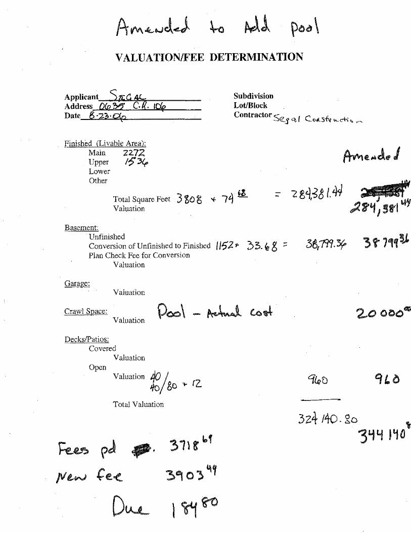
VALUATION/FEE DETERMINATION
Applicant ~4 ~ Address oL c. iefe Date g ·:z?,· c<p
Finished (Livable Area): Main 22.72 Upper !?')~ Lower Other
Basement:
Total Square Feet Valuation
Unfinished Conversion of Unfinished to Finished Plan Check Fee for Conversion
Valuation
Garage: Valuation
Crawl Space: Valuation
Decks/Patios: Covered
Valuation Open
Valuation 40 j ifo/ go ... rz.
Total Valuation
.P·
Subdivision Lot/Block Contractor So ( e_ L -=--j q, oll5""1\f ~A.-~.,. ........_
3z4 140. 2o ,,
'3'1Y l~ll
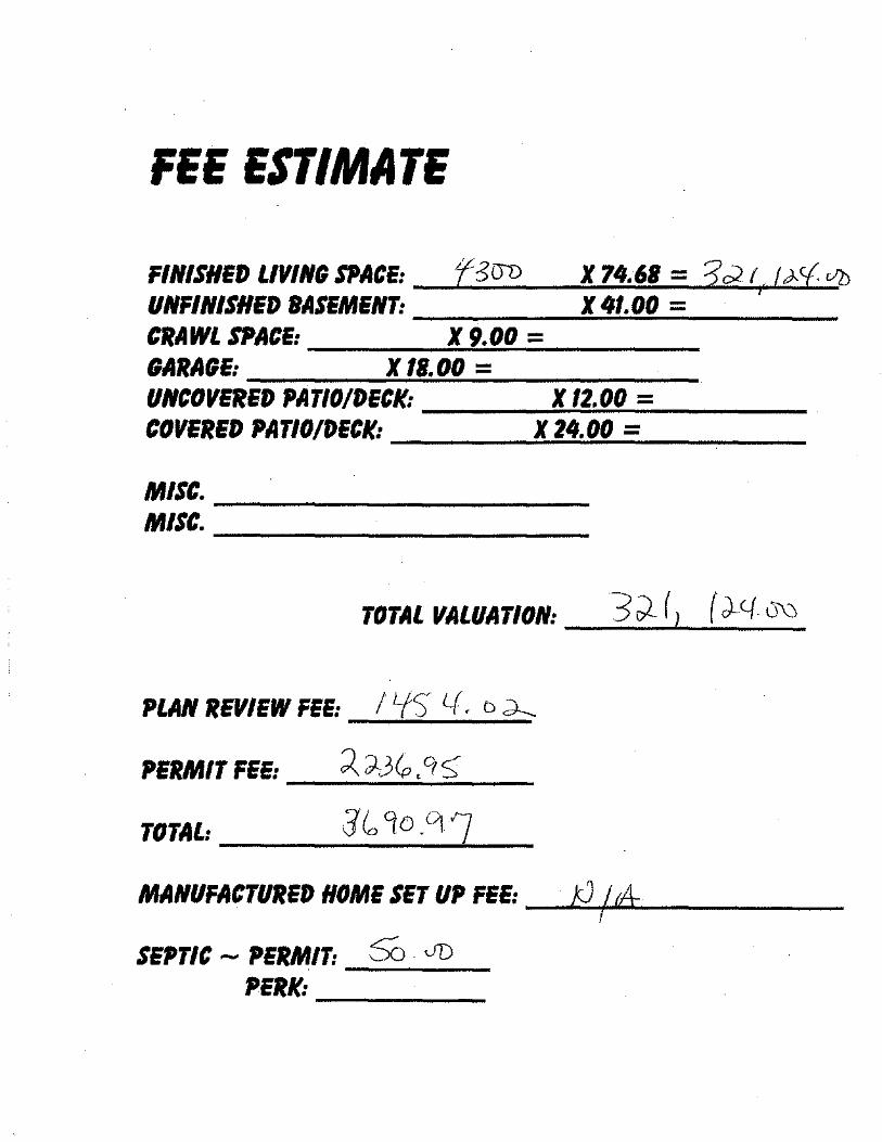
FEE ESTIMATE
FINISHED LIVING STJACE: _J-f.;:;.:5.;...cro _ ___.X:..:'f....:.<O:..:. 6,._1 -=--""'? ;2;,:;;;·..:.,f,o-~.. f.<;;;.,;_ cfJ-·..;;..cJ))
UNFINISHED BASEMENT: ____ ...:.X::...4~1.:.:.00::;.,.:;;= ___ _ CRAWL SPACE: X 9.00 = GARAGE: X lB. 00 = UNCOVERED PATIO/DECK: ----=X:-=1=2.'::-00::,.._= ___ _ COVERED PATIO/DECK: ___ __.,X-"2..:.:4·.:.:00.__= _ __,. __
MU~-----------MISC. -----------------
TOTAL VALUATION: 3 ,)_ ( 1 ( J.-c.f 0\:J
PLAN REVIEW FEE: I Lf) '-(, D d-..
PERMIT FEE: --~.;...~...;;.J...;;.(p..:...' '1...:.::;-;;....__
TOTAL: ___ J.:...io_<7_o_· (_1....~./ __
MANUFACTURED HOME SET UP FEE: __ .J.:;f)~jUI.rA-_.__ ____ _
SEPTIC - PERMIT: SO · JD PERK: ___ _
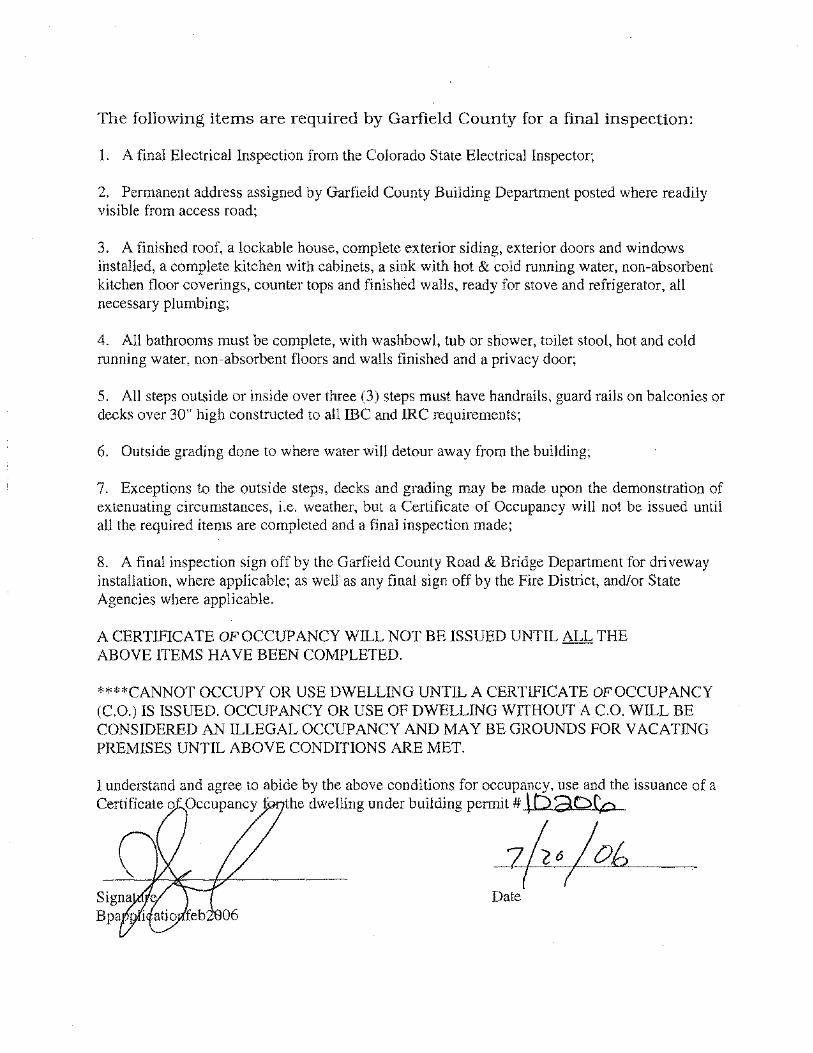
The following items are required by Garfield County for a final inspection:
1. A final Electrical Inspection from the Colorado State Electrical Inspector;
2. Permanent address assigned by Garfield County Building Department posted where readily visible from access road;
3. A finished roof, a lockable house, complete exterior siding, exterior doors and windows ihstalled, a complete kitchen with cabinets, a sink with hot & cold running water, non-absorbent kitchen floor coverings, counter tops and finished walls, ready for stove and refrigerator, all necessary plumbing;
4. All bathrooms must be complete, with washbowl, tub or shower, toilet stool, hot and cold running water, non-absorbent floors and walls finished and a privacy door;
5. All steps outside or inside over three (3) steps must have handrails, guard rails on balconies or decks over 30" high constructed to all me and IRC requirements;
6. Outside grading done to where water will detour away from the building;
7. Exceptions to the outside steps, decks and grading may be made upon the demonstration of extenuating circumstances, i.e. weather, but a Certificate of Occupancy will not be issued until all the required items are completed and a final inspection made;
8. A final inspection sign off by the Garfield County Road & Bridge Department for driveway installation, where applicable; as well' as any final sign off by the Fire District, and/or State Agencies where applicable.
A CERTIFICATE OF OCCUPANCY WILL NOT BE ISSUED UNTIL ALL THE ABOVE ITEMS HAVE BEEN COMPLETED.
'***CANNOT OCCUPY OR USE DWELLING UNTIL A CERTIFICATE OF OCCUPANCY (C.O.) lS ISSUED. OCCUPANCY OR USE OF DWELLING WffHOUT A C.O. WILL BE CONSIDERED AN ILLEGAL OCCUPANCY AND MAY BE GROUNDS FOR VACATING PREMISES UNTIL ABOVE CONDITIONS ARE MET.
1 understand and agree to abide by the above conditions for occupancy, use and the issuance of a Certificate o Occupancy f the dwelling under building permit# \ b 3D(p

VALUATION/FEE DETERMINATION
Applicant ~d ~ Address O/R C. icfe Date g ·2J,· C!p
Finished (Livable Area): Main 'Z-2.72 Upper I?~ Lower Other
Subdivision Lot/Block Contractor c-_ ( ~ "--
~j' ct. '-of\..5-w ,.__cf\ ~;,. ,......._
,. Total Square Feet 3 'tD g '< '74 _e_ Valuation
Basement: Unfinished Conversion of Unfinished to Finished Plan Check Fee for Conversion
Valuation
Garage: Valuation
Crawl Space: Valuation
Decks/Patios: Covered
Valuation Open
Valuation ... 12.
Total Valualion
3z4t4o. ~o
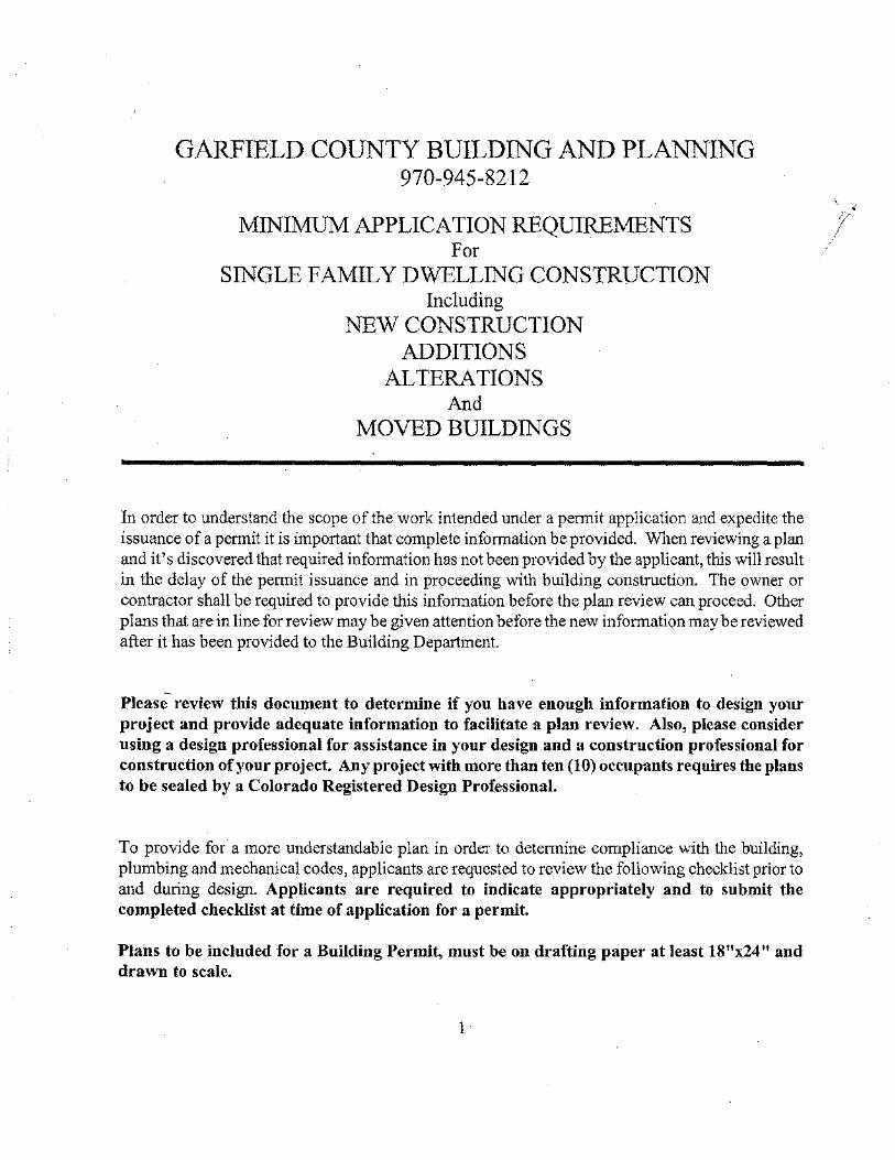
GARFIELD COUNTY BUILDING AND PLANNING 970-945-8212
MINIMUM APPLICATION REQU1REMENTS For
SINGLE FAMILY DWELLING CONSTRUCTION Including
NEW CONSTRUCTION ADDITIONS
ALTERATIONS And
MOVED BU1LDINGS
In order to understand the scope of the work intended under a permit application and expedite the issuance of a pennit it is important that complete information be provided. When reviewing a plan and it's discovered that required information has not been provided by the applicant, this will result in the delay of the permit issuance and in proceeding with building construction. The owner or contractor shall be required to provide this infmmation before the plan review can proceed. Other plans that are in line for review may be given attention before the new information may be reviewed after it has been provided to the Building Department.
Please review this document to determine if you have enough information to design your project and provide adequate information to facilitate a plan review. Also, please consider using a design professional for assistance in your design and a construction professional for construction of your project. Any project with more than ten (10) occupants requires the plans to be sealed by a Colorado Registered Design Professional.
To provide for a more understandable plan in order to deteiTiline compliance with the building, plumbing and mechanical codes, applicants are requested to review the following checklist prior to and during design. Applicants are required to indicate appropriately and to submit the completed checklist at time of application for a permit.
Plans to be included for a Building Permit, must be on drafting paper at least 18"x24" and drawn to scale.
1
' ' I '

Plans must include a floor plan, a concrete footing and foundation plan, elevations all sides with decks, balcony, steps, hand rails and guard rails, windows and doors, including the finish grade line and original grade. A section showing in detail, from the bottom of the footing to the top of the roof, including re-bar, anchor bolts, pressure treated plates, floor joists, wall studs and spacing, insulation, sheeting, house-rap, (which is required), siding or any approved building material. Engineered foundations may be required.
A window schedule. A door schedule. A floor framing plan, a roof framing plan, roof must be designed to withstand a 40 pound per square foot up to 7,000 feet in elevation, a 90 M.P.H. wind speed, wind exposure B or C, and a 36 inch frost depth.
All sheets to be identified by number and indexed. All of the above requirements must be met or your plans will be returned.
All plans submitted must be incompliance with the 2003 IRC.
1. Is a site plan included that identifies the location of the proposed structure or addition and distances to the property lines from each corner of the proposed structure(s) prepared by a licensed surveyor and has the surveyors signature and professional staf!lp on the drawing? Properties with slopes of 30% or greater must be shown on the site plan. (NOTE Section: 106.2) Any site plan for the placement of any portion of a structure within 50 ft. of a property line and not within a previously surveyed building envelope on a subdivision final plat shall be prepared by a licensed surveyor and have the surveyor's signature and professional stamp on the drawing. Any structure to be built within a building envelope of a lot shown on a recorded subdivision plat shall include a copy of the building envelope as it is shown on the final plat with the proposed structure located within 7nvelope. /) . (1 a ... Yes - Jse or urs.·~--to hHJ~ct,.,_holl\
2. Does the site plan also include any other buildings on the property, setback easements and utility easements? Please refer to Section 5.05.03 in the Garfield County Zoning Resolution if the property you are applying for a building pennit on is located on a corner lot. Special
setbacks d.JI'apply. ( <' · f J-' \ Yes ~ ~>t.!">l-i(J 1-hw tsc.s > (}''-'~""' t-->vrv0 l""'-'4: ""_;
3. Does the site plan include when applicable the location of the I.S.D.S. (Individual Sewage Disposal System) and the distances to the property lines, wells (on subject property and adjacent prop~s), streams or water courses? Yes ~
2
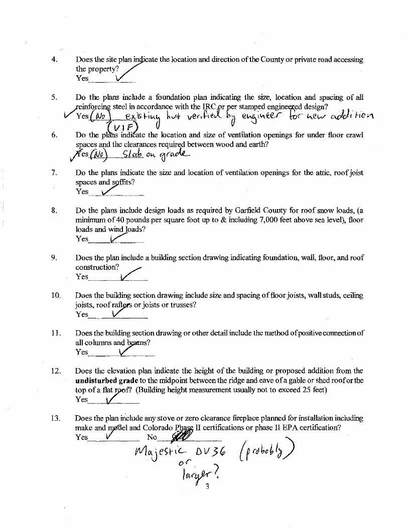
4.
5.
6.
7.
8.
9.
10.
11.
12.
13.
Does the site~lan in ·cate the location and direction of the County or private road accessing the property? Yes, ___ '<__
Do the plans include a foundation plan indicating the si7..e, location and spacing of all
.;-einforc, steel in ~c?rdance with the IRC;Pr per stamp,ed ~ngin~ed design? _, J, _ VYes{Jlo eJCISI--IIA~ hv<t- ver.~ •• ..x.. b;l e"6'"'eer t-oe "e""' ""-"""' hD>1
rv1F'\ u v Do the pl~ indi6ttc the location and size of ventilation openings for under floor crawl spaces and the clearances required between wood and earth?
.Jfes(ivo) £1ctb o,, 't)rtvk.-
Do the plan<i indicate the size and location of ventilation openings for the attic, roof joist
spaces 7:ffits? Yes · -- ·----
Do the plans include design loads as required by Garfield County for roof snow loads, (a minimwn of 40 pounds per square foot up to & including 7,000 feet above sea level), floor loads and wind loads?
Yes C Does the plan include a building section drawing indicating fooodation, wa11, floor, and roof construction? / Yes ____ ____jL ___ _
Does the building section drawing include size and spacing of floor joists, waH 51uds, ceiling joists, roof ~a.ftyts or joists or trusses? Yes V
Does the building section dra\'l!.'lng or other detail include the method of positive connection of all column.<; and ~s? Yes. ______ ~vrL_ ____ _ Does the elevation plan indicate the height of the building or proposed addition from the undisturbed grade to the midpoint between the ridge and eave of a gable or shed roof or the top of a flat !)>Of? (Building height measurement usually not to exceed 25 feet) Yes i.L
Does the plan irlciude any stove or zero clearance f-treplace planned for installation including make and,Iij0"del and ColoraJ~ II certifications or phase II EPA certification?
Yes V No -· )
----{111/"j eSHC... DV 3 (, {f rt!bc~ i;, or )~,-~~
3

14. Docs the plan include a masonry fire lace including a fireplace section indicating design to comply with tjae JRC?
15.
16.
17.
18.
19.
20.
21.
22.
23.
Yes if_ No_~~---
Does the plan include a window schedule or other verification that egress/rescue windows from sleepil}$ rooms and/or basements comply with the requirements of the IRC? Yes '\L'__ No. ______ _
Does the plan include a window schedule or other verification that windows provide natural light and venti tion for all habitable rooms? Yes No ______ __
Do the plans indicate the location of glazing subject to human impact such as glass doors, glazing immediately adjacent to such doors; glazing adjacent to any surface normally used as a walking surface; sliding glass doors; fixed glass panels; shower doors and tub enclosures and specify ¢ety glazing for these areas? Yes ·v No. ______ _
Is the location of all natural and liquid petroleum gas furnaces, boilers and water heaters indicated on Jhe plan? Y~ ·v No __________ __
Do you understand that if you are building on a parcel of land created by the exemption process or the subdivision process, are building plans in compliance with all plat notes and/or covenants? / Yes V No ____ _
Do you understand that if you belong to a homeowners association, it is your responsibility to obtain written permission from the association, if required by that association, prior to submitting an application for a building permit? The building permit application will not be accepted ~out it. Yes v' No ____________ __
Will this? only residential structure on the parcel? Yes No Ifno-Explain:
Have twopcomplete sets of construction drawings been submitted with the application? Yes \
Do you un7erst d that the minimum dimension a home can be on a lot is 20ft. wide and 20ft. long? Yes · No ____ _
4

24. Have you designed or had this plan designed while considering building and other constmctionco¥[equirements? Yes 1L No ____ _
25.
26.
27.
28.
29.
30.
31.
32.
Do your plans comply with all zoning rules and regulations in the Cimnty related to your properties zone dis · ct? Yes No ______ _
Does the p¥ran ac rately indicate what you intend to construct and what will receive a final inspection by: e Garfield County Building Department? Yes · No ____ _
Do you understand that approval for design and/or construction changes are required prior to the applicati£ of these changes? Yes ___ J ____ ~ No ____ _
Do you understand that the Building Department will collect a "Plan Review'1 fee from you at the time of application submittal and that you will be required to pay the "Permit Fee" as we11 as any "Road Impact" or "Septic System" fees required, at the time you pick up your building ~enyrl? Yes 1L No _____ _
Are you aware that you must call in for an inspection by 3:30 the business day before the requested inspection in order to receive it the following business day? Inspections "'ill be made from 7:30a.m. to 3:30p.m. Monday through Friday. Inspections are to he called in to }84-5003. Yes V No
~--·------ --
Are you aware that requesting inspections on work that is not ready or not accessible vvjlJ result in a $~0.0 e-inspection fee? Yes No
~--·--- ---~ -------~
Are you aware that you are required to call for all inspections required under the IRC including approval on a final inspection prior to receiving a Certificate of Occupancy and occupa~cy o - e building? Yes No -- ---~-- -------~
Are you aware that the Permit Application must be signed by the Owner or a written authority being given tOr an Agent and that the party responsible for the project must comply
with the IRC?v Yes No
5
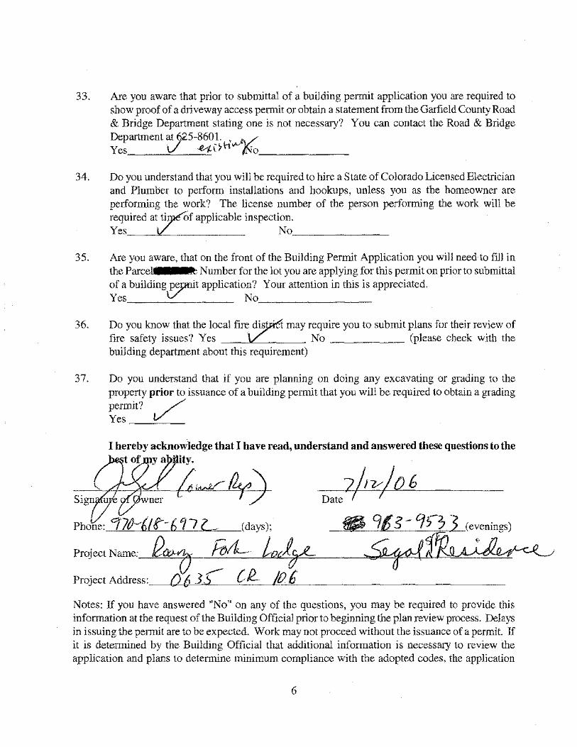
33.
34.
35.
36.
37.
Are you aware that prior to submittal of a building permit application you are required to show proof of a driveway access permit or obtain a statement from the Garfield County Road & Bridge Department stating one is not necessary? You can contact the Road & Bridge Department at (j25-8601. ·.,..A/ Yes V ~l>h: /No• ______ _
Do you understand that you will be required to hire a State of Colorado Licensed Electrician and Plumber to perform installations and hookups, unless you as the homeowner are performing the work? The license number of the person performing the work will be required atTf applicable inspection. Yes No _______ _
Are you aware. that on the front of the Building Permit Application you will need to fill in the Parcel Number for the lot you are applying for this permit on prior to submittal of a building~t application? Your attention in this is appreciated. Yes No
Do you kno:-v that the local fire~ may require you to submit plans for their re~iew of fire safety Issues? Yes No (please check With the building department about this requirement)
Do you understand that if you are planning on doing any excavating or grading to the property prior to issuance of a building permit that you will be required to obtain a grading permit? / Yes _ __,!./:___
I hereb~1 acknowledge that I have read, understand and answered these questions to the t of y a ity.
~~~~df f)> A\ wner ' 1/ Datef I
Notes: If you have answered "No" on any of the questions, you may he required to provide this information at the request of the Building Official prior to beginning the plan review process. Delay'S in issuing the permit are to be expected. Work may not proceed without the issuance. of a permit. If it is determined by the Building Official that additional information is necessary to review the application and plans to dctennine minimum compliance with the adopted codes. the application
6

may be placed behind more recent applications for building permits in the review process and not reviewed until required information has been provided and the application rotates again to first position for review, delay in issuance of the permit or delay in proceeding with construction.
Bpminreqfeb2005
7
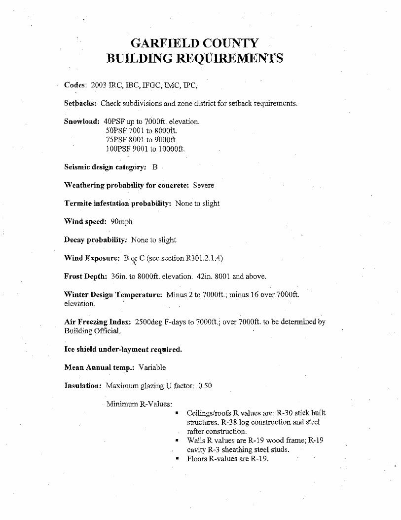
GARFIELD COUNTY BUILDING REQUIREMENTS
Codes: 2003 IRC, !BC, JFGC, IMC, IFC,
Setpacks: Check subdivisions and zone district for setback requirements.
Snow load: 40PSF up to 7000ft. elevation. 50PSF 7001 to 8000!t. 75PSF 8001 to 9000ft. 1 OOPSF 900 I to 1 OOOOft.
Seismic design category: B
Weathering probability for concrete: Severe
Termite infestation. probability: None to slight
Wind speed: 90mph
Decay probability: None to slight
Wind Exposure: B o,r C (see section R301.2.1.4)
Frost Depth: 36in. to 8000ft. elevation. 42in. 8001 and above.
Winter Design Temperature: Minus 2 to 7000ft.; minus 16 over 7000ft. elevation. ·
Air Freezing Index: 2500deg F-days to 7000ft.; over 7000ft. to be determined by Building Official.
Ice shield under-layment required.
Mean Annual temp.: Variable
Insulation: Maximum glazing U factor; 0.50
Minimum R-Values: • Ceilings/roofs R values are: R~30 stick built
structures. R-38log construction and steel rafter construction.
• Walls R values are R-19 wood frame; RM19 cavity RM3 sheathing steel studs.
• Floors R-values are R-19.

•
•
•
Basement wall R-values are R-1 0 be] ow grade, R-19 above grade. Slab perimeter R-value and depth is R-1 0/36in. Crawl space wall R-values are R-10 below grade and R-19 above grade
If floors over crawl spaces are not insulated, the crawl space walls mu&i. be insulated. Basement wall must be insulated to frost depth. Common walls garage to house must have R-19 insulation. Conunon ceiling/floor garage to house must have R-19. Take precautions to protect plumbing in these area.">.
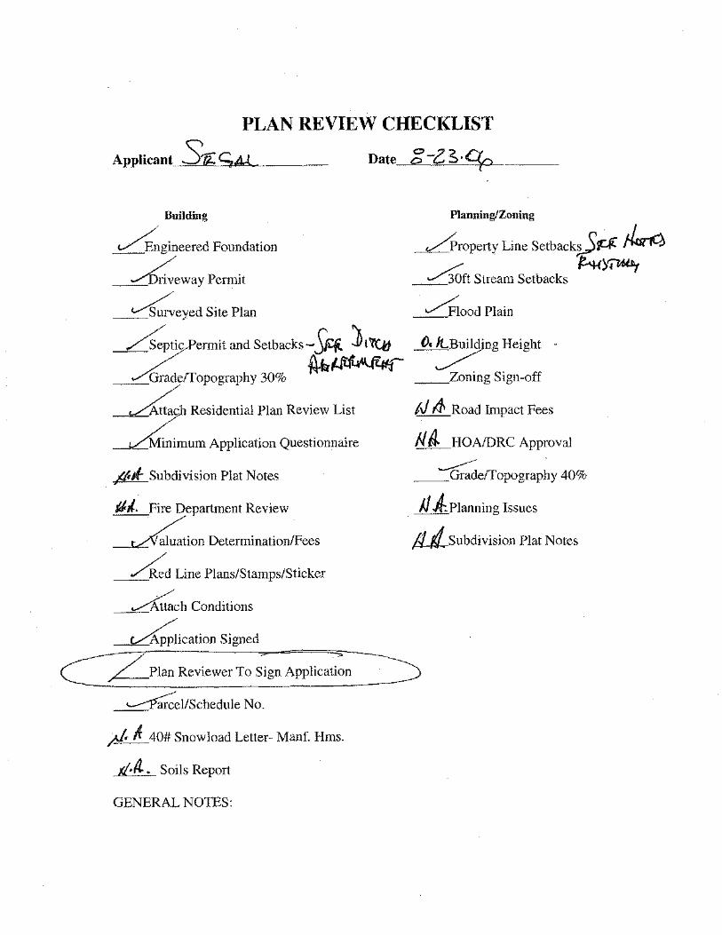
PLAN REVIEW CHECKLIST
ApplicantS~SM Date g-zs·q,
BuiJding
~gineered Foundation
~~eway Permit
~eyed Site Plan
~ZSeptic Permit and Setbacks-SRi. J t'l'Q1
f4-b~ __ Gradeffopography 30%
~ Residential Plan Review List
_Minimum Application Questionnaire
~Subdivision Plat Notes
JJJ.. Fire Department Review
~ion Determination/Fees
~d Line Plans/Stamps/Sticker
~~ch Conditions
Planning/Zoning
__Lrroperty Line Setback~~ ~ ~ft Stream Setbacks /!4{y;ul'1
/piood Plain
O, ~ng Height
__ Zoning Sign-off
/J fi Road Impact Fees
f.l iJ. HOAIDRC Approval ~ .
__ Gradeffopography 40%
JJ iPianning Issues
Usubdivision Plat Notes
~ication Signed C7 Plan ~eview_e_rc:'-[o~;-ig_n_A~p~pl~ic~a~t~:~
~~cl/Schedule No.
/1:k fr 40# Snow load Letter- Manf. Hms.
g.IL. Soils Report
GENERAL NOTES:
06-07-2006 13:21 DR SCOTT ALTER '370 9257221 9251178
July 6, 2006
Richard and Linda Segal 0635 County Road 106 Carbondale, CO 81623
To: Garfield County Building & Planning Dept. 108 8111 Street, Suite 401 Glenwood Springs, CO 81601
Fax: 970-384-3470
PAGE1
We authorize our son, Jason Segal to represent us in all business matters with Garfield County.
da S. Segal
RECEIVED JUL 0 6 2006
GARFIELD COUNfY BUILDING & PLANNING
)TES
N AN ~AN
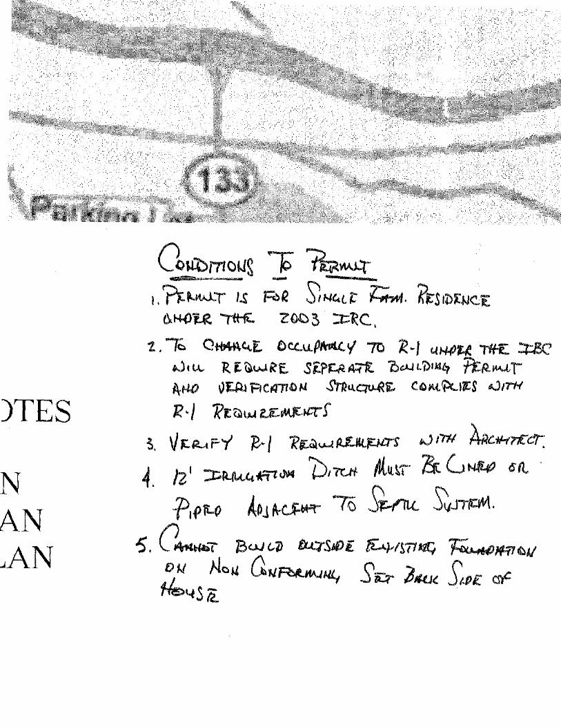
Co~mcws ~ ~~ ~"~~ .,.,,,... -
~,'n:P-~W-T /.s; !'=¢R s;I-IC.tl: ~. K~Stl)~.IJ~E 0. K-OU '('itii. Z oc ~ ::t: "R C. •
1.. /c, QHAA~E. Dc.c..u.Pfr141..'{ 70 'R.·J ~fo.I.()U T'lf£. :t:.l3C' .J, u.. R E ~wRE.. Si:?kll A-1-rt O.:JJ t7>tkll'f fi:R.~<·'-·"l'" f\.N-0 vEAl F'l CrQ"TT .C IJ fut.t~i:- C 0 M ~I ItS ..:Jtr'H
R ·I ~t {;\t>J f.ii:~!C!"" f
3. \} "f...P-t F-Y ~-/ 1?~<..1-4 PL~ ,j 1711 ARc.~Hn:c:r: 4. /21 :::J:;R..lk~.t*'flcJ\14 W!tc:...tl- M.u.IT· & GNt40 <S(l.
ftf>fi...() A~j t\-cJ:.Wf" -r;s s~ ~JT~. -5. (I ~T l3w <.:~ fJ...qS60 i fi4tS71 J.tC, ~1ft-, €:.&/
Df.J No~ G.u~ut S ") (' 1-k.4s k: ._, ~ .PIUJ~ Jt.P£ cs,e
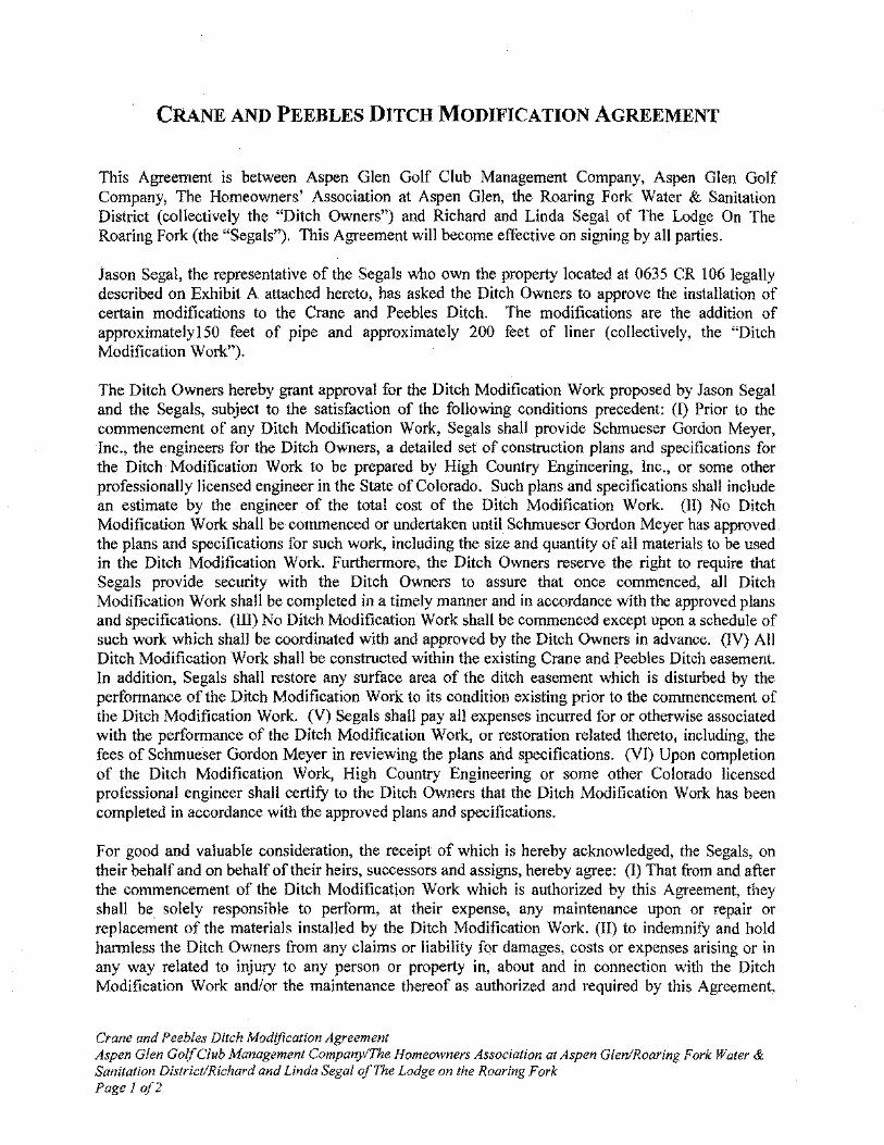
CRANE AND PEEBLES DITCH MODIFICATION AGREEMENT
This Agreement is between Aspen Glen Golf Club Management Company, Aspen Glen Golf Company, The Homeowners' Association at Aspen Glen, the Roaring Fork Water & Sanitation District (collectively the "Ditch Owners") and Richard and Linda Segal of The Lodge On The Roaring Fork (the "Segals"). This Agreement will become eflCctive on signing by all parties.
Jason Segal, the representative of the Segals who own the property located at 0635 CR 106 legally described on Exhibit A attached hereto, has asked the Ditch Owners to approve the installation of certain modifications to the Crane and Peebles Ditch. The modifications are the addition of approximatelyl50 feet of pipe and approximately 200 feet of liner (collectively, the "Ditch Modification Work").
The Ditch Owners hereby grant approval for the Ditch Modification Work proposed by Jason Segal and the Segals, subject to the satisfaction of the following conditions precedent: (I) Prior to the commencement of any Ditch Modification Work, Segals shall provide Schmueser Gordon Meyer, Inc., the engineers for the Ditch Owners, a detailed set of construction plans and specifications for the Ditch Modification Work to be prepared by High Country Engineering, lnc., or some other professionally licensed engineer in the State of Colorado. Such plans and specifications shall include an estimate by the engineer of the total cost of the Ditch Modification Work. (II) No Ditch Modification Work shall be commenced or undertaken until Schmueser Gordon Meyer has approved the plans and specifications for such work, including the size and quantity of all materials to be used in the Ditch Modification Work. Furthermore, the Ditch Owners reserve the right to require that Segals provide security with the Ditch Owners to assure that once commenced, all Ditch Modification Work shall be completed in a timely manner and in accordance with the approved plans and specifications. (lll) No Ditch Modification Work shaH be commenced except upon a schedule of such work which shall be coordinated with and approved by the Ditch Owners in advance. (IV) All Ditch Modification Work shall be constructed within the existing Crane and Peebles Ditch easement. In addition, Segals shall restore any surface area of the ditch easement which is disturbed by the perfonnance of the Ditch Modification Work to its condition existing prior to the commencement of the Ditch Modification Work. (V) Segals shall pay all expenses incurred for or otherwise associated with the performance of the Ditch Modification Work, or restoration related theretoj including, the fees of Schmueser Gordon Meyer in reviewing the plans and specifications. (VI) Upon completion of the Ditch Modification Work, High Country Engineering or some other Colorado licensed professional engineer shall certify to the Ditch Owners that the Ditch Modification Work has been completed in accordance with the approved plans and specifications.
For good and valuable consideration, the receipt of which is hereby acknowledged, the Segals, on their behalf and on behalf of their heirs, successors and assigns, hereby agree: (I) That from and after the commencement of the Ditch Modification Work which is authorized by this Agreement, they shall be solely responsible to perform, at their expense, any maintenance upon or repair or replacement of the materials installed by the Ditch Modification Work. (II) to indemnify and hold hannless the Ditch Owners from any claims or liability for damages, costs or expenses arising or in any way related to injury to any person or property in, about and in connection with the Ditch Modification Work and/or the maintenance thereof as authorized and required by this Agreement,
Crane and Peebles Ditch Modification Agreement Aspen Glen Go(( Club Management Company/The Homeowners Association at Aspen Glen/Roaring Fork Water & Sanitation District/Richard and Linda Segal of The Lodge on the Roaring Fork Page I of2
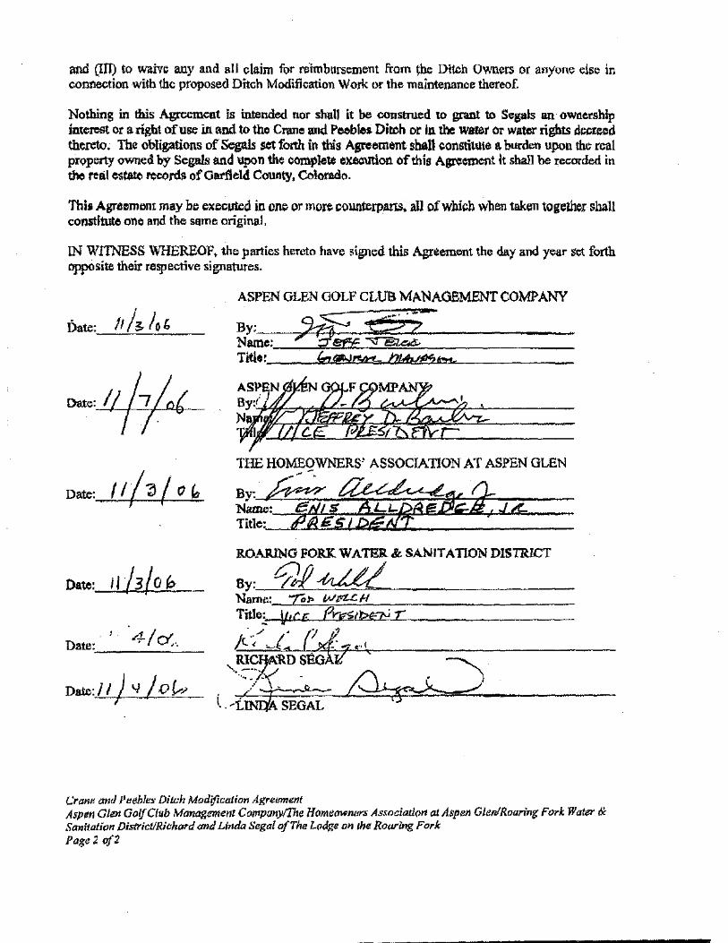
and Cim to waive any and all claim f~;tr te'imbursement from the Ditch Owners or anyone e.ls~: in connection with the proposed Ditch Modification Work or the maintenance thereof.
Nothing in this Agreement is intended nor shall it be constnl.ed to grant to Segals an ownership interostor aright of use in and to tho Crone ond Peebles Diroh or In the warer or w-rights decreod thereto. The obligations of Segals set forth in this Agreement shall constiiUte • burdon upon the real property owned by Segals and upon the complete execution of this Agro=ent It shall be recorded in the realos~ reoold• of Oarlleld COUJ!ty, Colorodo.
Thi• Agreomcnt may be executod in ono or more countcrpa.ns. all of which when token together shall constitute one and the same original,
IN WITNESS WHEREOF. the pnrties hereto have ~igned this Agreement the day and year set forth opposite their respective signatures.
Date:
Date:.~_~_'-..:./..:.0':..:.·..:.·· _
Daro:l/ ) 'I /0 fv;o I
ASPEN OLEN GOLF CLUB MANA<.lEMENTCOMJ>ANY
~~~,--,;~~~~~eeE~~~;;&~·-~:~r:_.~-----------Tltl .. --~...,;<->=@:!=......_-""'m""""~=--...,-_------
Crane and Peeble:.· Ditch Modifica/ior~ Agre1m1ent AsN" Glen GalfCJub Management COJtf.pany([he Homeowne/"S As.mciation at Aspen Glen/Roarinr; Fork Water & Sanitation /)istrict/Richard and Lirula Segal ofTiw l.(ldge DH the Roaring Fork Page2 of2
Bill To:
10 39\Jd
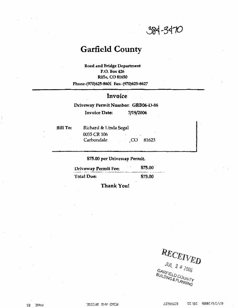
Garfield County
Road and Bridge Department P.O. Box426
Rifle, CO 81650
Phone-(970)625-8601 Fax- (970)625-8627
Invoice Driveway Permit Number: GRB06-D-86
Invoice Date: 7/19/2006
Richard & Linda Segal 0035CR 106 Carbondale ,co 81623
$75.00 per Driveway Permit.
Driveway Permit fee: $75.00 · _., ..... -- ____ , ···------ .. ·-----·-· -------~---·----- ...
Total Due: $75.00
Thank You!
390H::l8 ON\d O'liO'C:! LZ989Z9
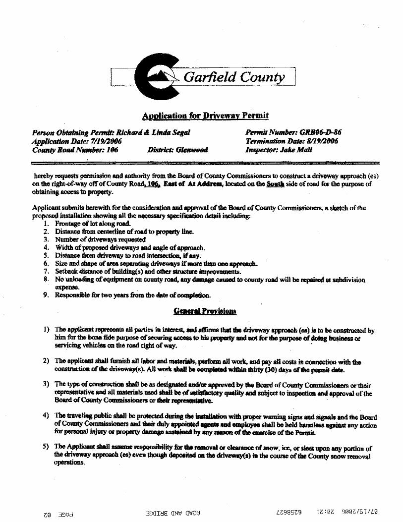
Garfield
t\Pplieatiog for Driveway Pewit
Pen()# 0/Jttllnlng POI#It: Riclltll'd & Lllldir Segal Pmffi1 N-: GRBIJ6-D-86 App/ictllion Dak: 7/1911006 TtrmiJUJtlmt Dille: 8/19/1006 CoiiUity RmulN-: 1116 Dislrlct: GIM- lnspuJQr: J<Jke Mall
hereby roqueots perm;,.kon and aothority tiomtlle l!qord ofc-y C<munlssionas 1X> <OD>ituct a driveway BJI!l<OaCh (es) on the ril!bt-of.way off of County~ Eat of At AAidnu, looated on the l!u!k side of rood for the poupose of ohtainina aoom to Jli'OI!OdY-
Applic:ant submito horowith fur the c011Sidoralkm and _,.J of the l!qord of County ('""'""issiooem, • .-b of the propo!O>d installation ohowina an the.........,. spocilloatioo dotail ~
L FrolJII8eoflotaloogrood. 2. Di--~ofrood1X>JOoporlyllno. 3. Number of -Ill" requestod 4. Width of pmpoood driveways ond angle of IIJ'Pl'<"''h. S. Di-&om driveway"' rood intofteclioa, if IllY· 6. Size ond shape of ana sepilnltU>gdrivawoyo if IliON tboa .,..._... 7. Setback di- ofboilclillg(s) and other-~-$. No unloading of equipment on county ros4, tiny.._ OOUIOII to CQII!Ity rood will be ropaimd 01 aebdivision -· 9. Ro.ponaible fur- yoars &om tile dOlo of.........-.
SdMralllllt'lo!ow!
1) The app!iclmt "'"'...,...an pa!lies in-.., ond --tile driveway _.,..m (es) is to be -.....I by him for the oo.a fide- of""""""..,.... to Ills ll"'JJllRY-'notfurtbo- of doing llwlb888&ot ...,Ieins vehielco on tho rood ril!bt of..,.y. ·
2) The appliclmt sball furnish allltlbor .oo l1llltorills, J*li>lm an wotlc.. .oo poy all oosto .,_with tho COOW!odioo of tho dri""""J'(s). All vmrk sbaR be eOIIIPioCo4withinthlny (30) dayooftho"""'"' dOlo.
3) The type of-sball boas dcoipated OlldicJr_.....t by tile Board of County C.........._. or their ~ve-' an -.us used sbaR be of ..,dof>otooy quaRty-' ~oct to~""-' llpp!Oval of tho Board of County COIIIIIIilJsiooors..-thoirrq>r-.
4) The traveling poblie sball be""*""""' during tile imtallo!ioq with proper"""'""" sip and sigoals-' the Board of County C.........i<mors-' their duly appoiniOd ...,._and empk>yeo sball be bold botmleoa apUtst ony action furpenoooal i'lilllY or ll"'JJllRY .._au-by OilY- oftile......,;ao oftho Ponnit.
S) The Applieoot sball- respoosibliity fut lbo.......,... or-.....,. of BOOW, ice, or sleet 11po0 aay porrioo of tho driveway oppl"<lll<b (os) oven though depooilod Olllbo dri""""J'(s) ill !be""""" of tho County snow mnoval openttinns.
Z0 39'dd 39011:!8: ON\/ GtiOC! LG98SZ:9

6) In the event it becomes necessary to remove any rigbt-of .. way fence, the posts on eithet side of the entrance shall be surely braced before the fert:(:e is cut to prevent any sla(;king of the remaining fence and all posts and wire ron><>ved shall be turned over to tho Ddorict ~loadS~ of tho- of County Co-'ss'-"'·
7) No revisions or additioos sluoll be rnado ro tho driveway(•) ar its~ on 1he riiJht-of-way willlout wri- permission of tho- ofColmly CommissiOIItll!l.
8) ProvU.ions and spocificatioos outlin<:d OO..ia sluoll apply on all l:(Jolds under the jurisdiction of 1he Boonl of County Commisolone" ofOarliold County, Co!Mdo, and 1he SP"'ifko1ions. set forth on 1he attad>ed henwf and lnoorporalild iloRin .. cooditions botoof.
9) FIDIII bupe<tioa of dn.-ywJU be reqalnd opoa ..,.p~et~oa ud •ut be app""""" by,.....,. lulling poi'IIOitor~ofponoalulllq P"'.-it.
. TH bupe<tloa aad o~p orr-bo ._ pr1or 1o uy co trom Ike Builcliatl ud p, .... ;., Dopmmeat belq loaaod.
1. Driveway Widtlt- 30ft l. ColYer! reqlliNd? 1'- Slu• by 3. Asp!utltor.......,.podroqalndTT- Sluofpadt31ftWhle•leftlollc•4hiiU<k 4. Gnml pot1iml reqalnd? F- Loqtil• 5. T--·---lobo.__lar~ F-
6. ---·· 7. CertillodTrollleC..-~? 11-8. Worbou olpn"''alred? y,.
In signing 1hls application ami upon rooeiving au1ll<>rizatioo and pomU,.loo to install tho driveway"""""""' (eo) descril>ed bonrinlho AppliCOI<! signifies thai be boo rood,..-and...,...,.. tho fufegoinJ .,.....-and cooditions and RgJ<OS ro<XliiJJiruct the driveway(s) in--willllho ~sp<cili<atioo ploo reviewed ami approved
by 1ho Booro of County~ ...
Richaid & Linda Segal Add.-, ---
T~~Nw.Mr.. ______________ ~-----
Permit gnmtod 71l?a91!6. subjoct to the provilloao, ------.. atl ........... robt.
/:or Booro of County~· ofOarliold Couoty, Colorndo:
~ • ofG..-fiold County Rood and Bndgn Signature
£0 39'1d 390I~H ON\J OVO~

Specifications
1. A driveway approach is understood to be that pOrtion of the county road right-of way between the pavement edge and the property line Ibm is designed and .....I for the inte<cluulp of1rnft""IC between 1he roadway and ob\ddng property.
2. At any inteTsection, a driveway shall be IC$1rlcted for a sufficient distam:o :from the intenedion to preserve the normal and safe movement of traffic. (It is recommeuded for rural residence entnmces tim a minimum illter!ieotioo e.....,.ce of SO feet be provided and for tw:a1 coom•:rcial elltrance1i a minimum of l 00 feet be provided.)
3. Allentnmces and exit> shall be so l~orulconsuucted tbatvobi<:ks approocblng or using them will be able ro obtain adequate sight distance in both dlroctions a1oog 1he ~rood in order to maneuver safely and wilhout iniOdloring wilh ~rood \ndlic.
4. The Applicaot obali 1101 be ponniUed tn.-any oiau or display ......,;..J, either fixed or movoble, on or extoruling aver any portion of 1he county rood riglrt-of•WII)I.
5. Gencrolly, no more ilwl ooo approocb shall be allowed any 1""""'1 or property the frontaau of which is less thon ooe hundred (100) lOot. Additionolentnmoos or exits for pan:ols baYing a frontage in"""""" of ooe hoodred 100) feet oball be ponniUed only aftorshowingof-............, and -.by.
6. All driveways shall be so l...u.cllhm1he fWod portion adjacent to the traveled Wtty win not encroach upon adjoining property.
7. No ..,..,....ial driveway shall bave a width sr.w ilwl thirty (30) feet meatlllJ<d at risfrt anps tn the centerline of the driveway toreept as inereasod by penllislible ...W. No ll<lliCOIIIIBCICial-ewtty shall bave a width~ ilwl twenty (20) feet measured at risfrt anps "'the-of the driveway, elWeplas inereasod by permieoible radiL
8. The axis of an approocb to the rood unty be at arisfrt lilgie to the -lloe of the~ rood and of any angle between ninety (90) de..-and oisty (60) clesrco• but obali not be leas ilwl sixty (60) de..--Adj-will be mode acoordinl tn the type oftratllc., be-ood - pllysieal --·
9. The COilSiru<liHm of pouldng or servicing areas oe 1he ~ -' risfrt-of·way is speeilieally prohibited. Commercial estahllshments for • ....,_. vehicleo sbould pcovide oJl'..the.rood puking &on-.
10. The &f8do of ontranoe and exitsludl slope downwotd aod- ftomthe road surface at the,....- as the normal sholllder slope and for a distance equal to the width of the sholllderbut in no"""" less than twenty (20) feet ftom the pav-edge. Approlch l!l'ldOs .. notriQied tc> not....,. than""' - (10%).
11. All drivewttys and -bes oball be so eonsa:ueted tbat they obali not ~with the dtalnage system of the ..,.... or~ road. The Applicant win be required to pnWi4oo, ot hiaown expenoe, ~ sttucturos at entnmoos aod Old1s, which will become an ~ port of the .. isting dtalnage system. The Board of County Commiuioners ortheirropmeotativo, prior to -!ladon, mnat -·• the--and types of all~ -·
Note: Tllll perlllltollaii be-• .....O.W.IItth""-"' .... od-work Is bela&....._ A worll.olooleio or drawinl of the propooed drlv.,.ay(ll} mliOI--a~l'lo ponolt wlll be ........ -... dra""'-'
b ............ ...
1?0 3817d 39aiCJS: GNt' G\70Cl LZ989Z:9

~tech HEPWORTH- PAWLAK GEOTECHNICAL
April l3, 2006
Lodge at the Roaring Fork c/o Jason Segal ll 0 Easy Street Carbondale, Colorado 81623
Hcpwonh-Pawlak Geotechnical, lnc:. 5020 Coonly Road !54 Glenwood Springs, Colomdo til60l Phone: 970-945-7988
Fax: 970-945-8454 cmatl: [email protected]
Job No. 106 0222
Subject: Percolation Testing, Addition to Existing Residence, County Road 106, Garfield County, Colorado
Dear Mr. Seagel:
As requested by you, Hepworth- Pawlak Geotechnical, Inc. performed percolation
testing at the subject site. The work was done in accordance with our agreement for
professional services to you, dated March 8, 2006. The property is occupied by a two
story wood frame residence and serviced by a septic system.
The residence is located on a relatively flat and narrow topograghic bench below
County Road 106 and above the Glenwood Ditch and Roaring Fork River. We
understand the existing leech field is located below the gravel driveway and will be
enlarged to accommodate the proposed addition.
A profile pit was excavated on March 9, 2006 at the location shown on Figure 1. The
subsoils exposed in the Profile Pit consisted of about 4 feet of manplaced fill overlying
silty sandy gravel with cobbles and boulders to the bottom pit depth of 8 feet. No free
water was observed in the pit and the soils were slightly moist to moist. A percolation
test hole was hand dug in the natural gravel soils, and soaked with water on April3,
2006. Location of percolation test holes was limited due to existing utilities and septic
system.
Percolation testing was performed on April 4, 2006 by a representative of Hepworth -
Pawlak Geotechnical, Inc. The percolation test results are summarized on Table 1.
Parker l0l-R4l-7l19 • Colorado Springs 719-633-5562 • Silverthorne 97,9-468-1989

. Lodge at the Roaring Fork April 13, 2006 Page 2
Based on the subsurface conditions encountered and the percolation test results, the
tested area should be suitable for a conventional infiltration septic disposal system.
If you have any questions or need further assistance, please call our office.
Sincerely,
HEPWORTH- PAWLAK GEOTECHNICAL, INC.
/''
~-- , ~0=/Z::V~) (/-'~r..;e-../
Louis E. Eller ·
Reviewed by:
Daniel E. Hardin,
LEE/kmm
attachments Figure 1 - Location of Percolation Test Holes Table 1 - Summary of Percolation Test Results
Job No. 106 0222

NOTTO SCALE
"' 0 ~
0 <{ 0 a:
~ :::J 0 0
EXISTING r----, RESIDENCE
P1
.,6. PROFILE PIT
I g 0 0 0 0 :;: z w ~
"'
TO HIGHWAY 82
106 0222 ~ LOCATION OF PERCOLATION TEST HOLE HEPWOR11+PAWLAK GEOrECHNlt;Al.,
a: w <: a:
"' a: 0 "-
"' z a: (§ a:
Figure 1
I I
I
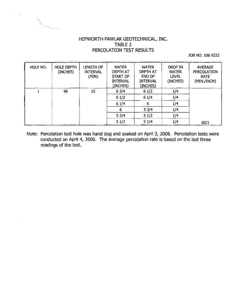
HOLE NO. HOLE DEPTH (INCHES)
1 96
J
HEPWORTH-PAWLAK GEOTECHNICAL, INC. TABLE 2
PERCOLATION TEST RESULTS
~
LENGTH OF WATER WATER INTERVAL DEPTH AT DEPTH AT
(MIN) START OF END OF INTERVAL INTERVAL (INCHES) (INCHES)
15 6 3/4 61/2
6 1/2 61/4
6 1/4 6
6 5 3/4
5 3/4 51/2
5 1/2 51/4
I
JOB NO. 106 0222
DROPIN AVERAGE WATER PERCOLATION LEVEL RATE
(INCHES) (MIN./INCH)
1/4
1/4
1/4
1/4
1/4
1/4 60/1
Note: Percolation test hole was hand dug and soaked on April 3, 2006. Percolation tests were conducted on April 4, 2006. The average percolation rate is based on the last three readings of the test.
I
I! I I
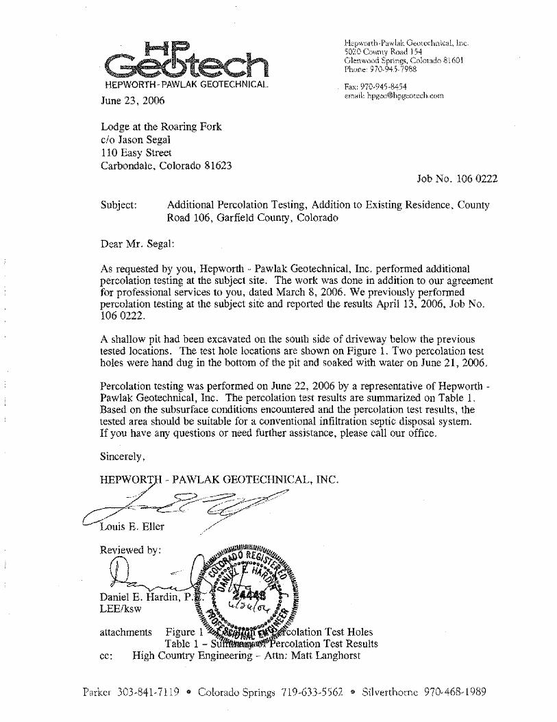
~tech HEPWORTH· PAWLAK GEOTECHNICAL
June 23, 2006
Lodge at the Roaring Fork c/o Jason Segal 110 Easy Street Carbondale, Colorado 81623
HetJWorth-Pawlak GeotcchniC<tl, lnc. 50Z0 Co11nty Road 154 Glenwood Spring>, Colorado 81601 Phone: 970-94.5· 7988
Fax: 970-945-8454 <cmHil: [email protected]
Job No. 106 0222
Subject: Additional Percolation Testing, Addition to Existing Residence. County Road 106, Garfield County, Colorado
Dear Mr. Segal:
As requested by you, Hepworth- Pawlak Geotechnical, Inc. performed additional percolation testing at the subject site. The work was done in addition to our agreement for professional services to you, dated March 8, 2006. We previously performed percolation testing at the subject sit'e and reported the results April 13, 2006, Job No. 106 0222.
A shallow pit had been excavated on the south side of driveway below the previous tested locations. The test hole locations are shown on Figure 1. Two percolation test holes were hand dug in the bottom of the pit and soaked with water on June 21, 2006.
Percolation testing was performed on June 22, 2006 by a representative of Hepworth -Pawlak Geotechnical, Inc. The percolation test results are summarized on Table 1. Based on the subsurface conditions encountered and the percolation test results, the tested area should be suitable for a conventional infiltration septic disposal system. If you have any questions or need further assistance, please call our office.
Sincerely,
Rev,ewed by:
.c-•"
attachments Test Holes Table 1 - Test Results
cc: High Country Engineering- Attn: Matt Langhorst
Parke< 303-841-7119 • Colorado Springs 719-633-5562 • Silverthorne 970-468-1989

NOT TO SCALE
"' 0
0 <: 0 X
I: z :0 0 ()
TO HIGHWAY 82
EXISTING .----,RESIDENCE
:.. !I
if: ii' Q
0 ~
P2
§ P1
oLO. PROFILE PIT
LEGEND:
75'
I
f2 0 0 0 0
"' z w -" l9
rr w ;,;:;
"' rr 0 CL
l9 z B'
C5 rr
A PERCOLATION TEST HOLE FOR THIS STUDY.
£:. PREVIOUS PERCOLATION TEST HOLE
106 0222 ~ LOCATION OF PERCOLATION TEST HOLE Figure 1 HW'WORTI+PAWlAK GEOTECHNICAL
' HOLE NO.
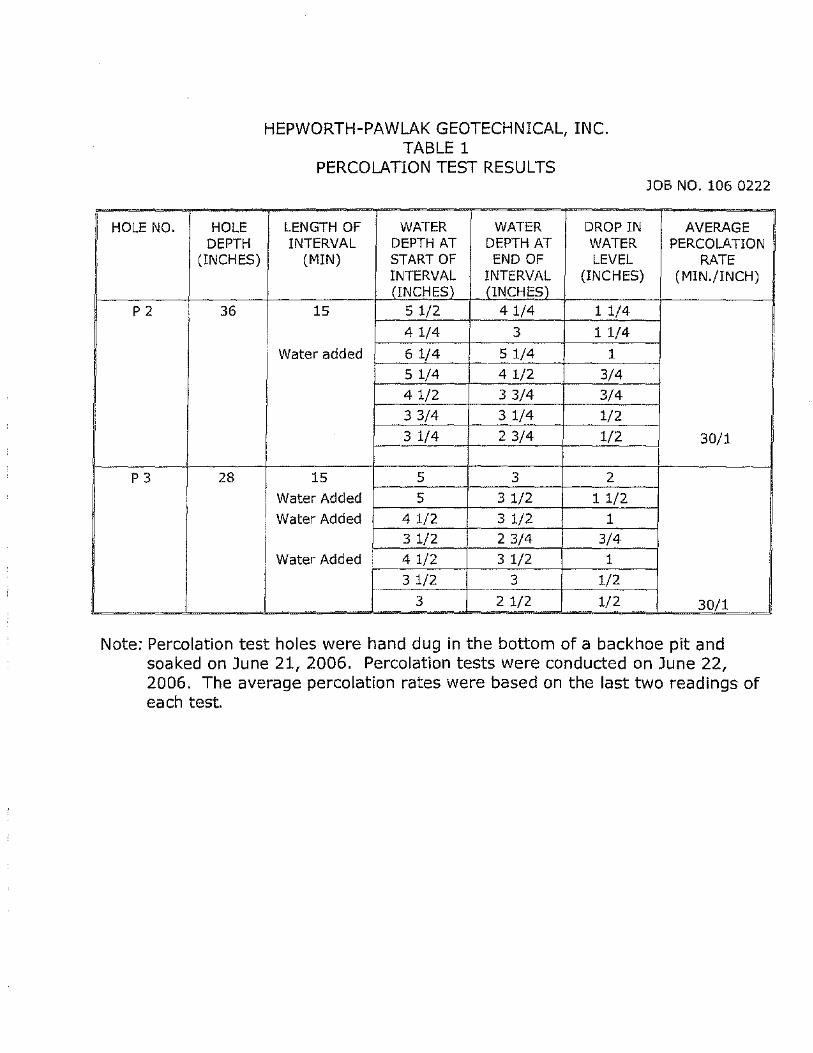
P2
P3
HOLE DEPTH
(INCHES)
36
28
HEPWORTH-PAWLAK GEOTECHNICAL, INC. TABLE 1
PERCOLATION TEST RESULTS JOB NO. 106 0222
I
LENGTH OF INTERVAL
(MIN)
15
I Water added
15
] Water Added Water Added
WATER WATER DEPTH AT DEPTH AT START OF END OF INTERVAL INTERVAL (INCHES) (INCHES)
DROP IN WATER LEVEL
(INCHES)
51/2 41/4 11/4
4 1/4 3 1 1/4
~_1_/4'---t----=-5 1/4 1 5 1/4 4 1/2 3/4
4 1/2 3 3/4 3/4 3 3/4 3 1/4 1/2
_3 1/4 2 3/'-'4-+-_1,_/:=_2_.-j
I 5 3 2
5 3 1/2 1 1/2
4 1/2 3 1/2 1 3 1/2 2 3/4 3/4
Water Added ,--..:.4_.1o_:/2:__-+--"3'-'1"-/"-2-+ _ _::.1_---i 3 1/2 3 1/2 ··-· ·-::-'"c::---r--=c:---i
3 2 1/2 1/2
AVERAGE PERCOLATION
RATE (MIN./INCH)
30/1
30/1
Note: Percolation test holes were hand dug in the bottom of a backhoe pit and soaked on June 21, 2006. Percolation tests were conducted on June 22, 2006. The average percolation rates were based on the last two readings of each test.
Mr. Richard Segal II 0 Easy Street Carbondale, CO 81623 June 14, 2007
Re: Property at 0635 C.R. 106, Carbondale, CO.
Dear Mr. Segal:
Garfield County BUILDING & PLANNING DEPARTMENT
This Jetter is to clarify that approval of your property for use as a lodge will hot happen until the results of the Conditional Use Pennit are known. Recently, an amendment to the existing building permit was approved that allowed for some changes to meet the building code requirements for a lodge type of occupancy requirements. A condition to the existing pem1it is approval of all land use requirements prior to the building being used as anything other than a single family dwelling. The present building pennit as amended is only for a single family dwelling.
Please call if you have any questions.
Andrew Schwaller Building Official, Garfield County
108 Eighth Street, Suite 401 • Glenwood Springs, CO 81601 (970) 945-8212 • (970) 285-7972 • Fax: (970) 384-3470

CIVIL ENGINEERING
May22,2007
Andy Schaller Garfield County Environmental Health 108 gili Street, Suite 201 Glenwood Springs, CO 81601
Re: Lodge at the Roaring Fork ISDS HCE Project Number 2061009.00
Dear Andy:
LAND SURVEYING
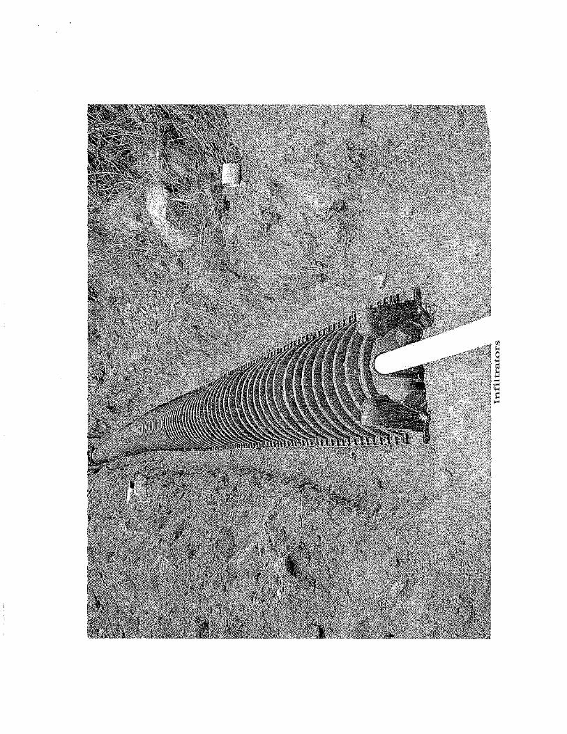
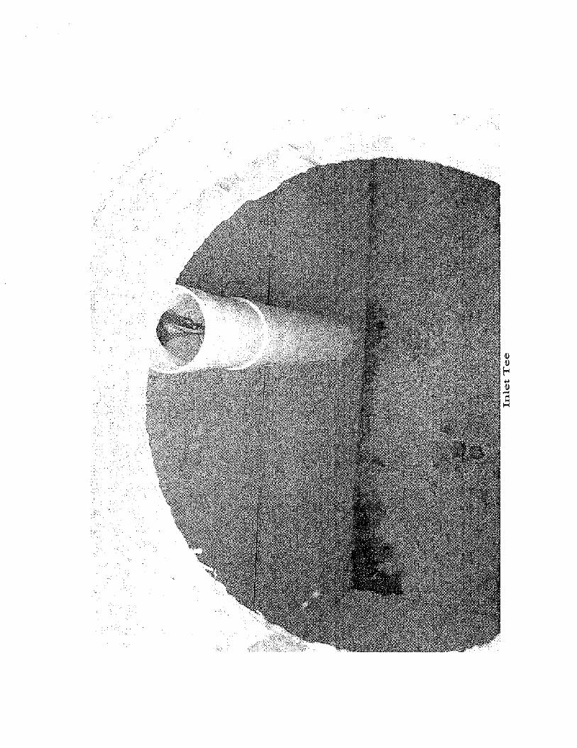
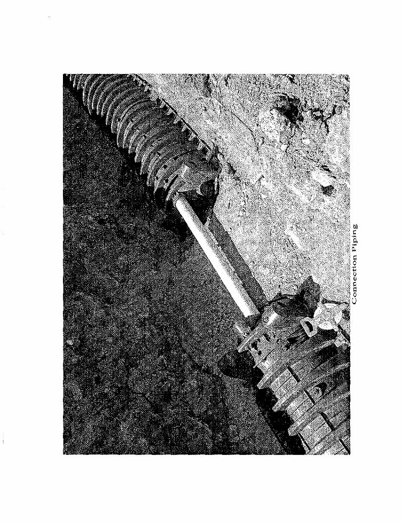
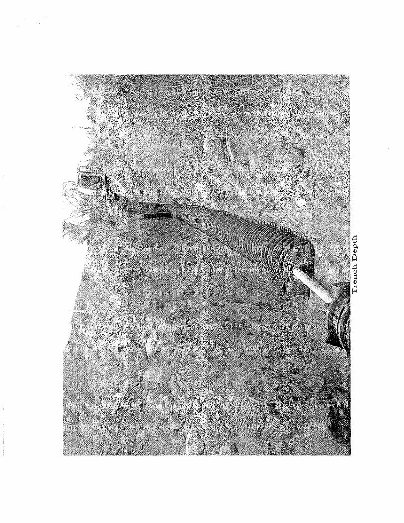
The full owing letter is to confmn the engineer's acceptance of the designed septic system of the Lodge at the Roaring Fork on County Road 106. The design included a 2,000 gallon septic tank, and 77 infiltrator units. All of the inspection wells, infiltrators, manifolds, and cleanouts were inspected and were installed satist8.ctory, and can be seen on the as-built drawing.
The system has been completed with the intent of the original design.
If you have any questions, or need additional information, please contact us.
Sincerely,
1517 Blake Avenue, Suite 101 Glenwood Springs, CO 81601
970.945.8676 phone 970.945.2555 fax
www.hceng.com
MAY 2 2 2007
14 Inverness Drive East, Suite F-120 Englewood, CO 80112
303.925.0544 phone 303.925.0547 fax
..
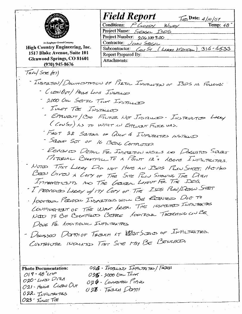
Field Repo,-_t t;:;; Date: 4 /;o I o 7
Conditions: ? ~"oy M~c::Y Temo: 4-8 • Project Name: _c;r:;:~£- I~ps
Project NUlJ)lJ."r:___t2.Qt;.JCQ y.co -·-~
Contractor: JL!;;cJ £e;u 1.-~-----·
M Employe<--0~ C-.-y
ering, Inc. High Country Engine 1517 Blake Avenue, Glenwood Springs; C
(970) 945-867
Subcontractor: r:.v £y ( L6,a.-.~z~ 1::/Z..~o. '-} 3J6 ·4.5.30 Suite 101 Report Prepared B;:'-~-· 0 81601 ---~-----------.
Attachments: 6 ·---· ---- --
;,;;;~; Srx in)
(_,V n c:?.J'7'1:--n 0 0 t1 r - I(,b >'tL-7iOJ I Do c !btU tJi/7 1 .QIXO v<~
kL<'T
!fL7l~t.- J;;bT-rLJ.....l-7fiJO c>F I>..os /r~ fV"u..ovJ.>:
j,I,Ch-6 L,~.; hwx"-= ~Tic..- IT~ r~s.7;<:~
I= .I;;,~ jl2:>JO hL-/.:.::;:2_ JJor E.::.TA~- h _, ra.vur .:::P • &F7"Lv~
{ cCuv f. >) h> 7V WHL-r --<.J ~o....rr FT,_:Tt.:e- VA~.
/!. $ct..-7Tc)i-J.},. OF a,<-K"' IUAt..-le.L~ /JJS7?tu...~
S:cr Of< I? /3e;><:. Con/'4.-r=
- h2.bT ;1.
- 5ae-- E'evrcw c::::> Oe7AI<- Fi£_ _LJ.-)::,0Z-77o0 u.JC[....J._.S .(.a P>Gvsr=
~
c;CL~:>..,
L-J?tT<>"lA
,U OTCD 7/r;_ -r /3.=;_-v cPIYL"V
:z;, !">I!CYQ-7c:J._}7;
~Pit-~lo A -Po::)Jf " /2 7 A-!3.o r"C::: ~A<.... TI'<..A. ToZ.S.
L~ Qp ,U{rr /hvc Af.) f_sp_s ;u._, S·tcer: !-f.c-1-k= A ?-<>ry OF 7/ie Srrc /Z:.,{..; S:HOw ;vc, life C?nrt ~ A..o 7/fe ~ay,~ /..,.<ydvr' ;::;;;_ ~ ..r:,ps_
• T;"'eov?e>c'B?,~ y ,_y /-?)" ~ry (J>F' 7/ft: L= f'l,uJ j.£:6<:-,J SrilET
- 6Cf 4-wv<e= f7vc- -ra 001,__ ,J-N;;.ra-!fo~ Wf'-'-;(~. -rti£ ;v;<Pa-7Tr? ;J:iJR<-.._"""
)pprr<W"- pez, (;o,.; F1 l"'f0<7eVT'
v= rv 6"' Povc: fU.. A'=
0,. ""' IJ.J~ __,_.- J & 6.ro<Ff.J~.L.--v:::> {3Cfiiec;: /c>PtiTOIJ,l'- I !2CJCC.ti1~6 c..~. ,
~
t/100(.<.-- J---~Fi!Jle;..._-rn::_s.
OF ~ctt - ~>= 1/CA?i Lo )J']J2+<71ie- I !...J~C-J-fl';::;> /;'"'
,({ War. 50'> ""' DF It->ALTr'ZATreb.
Sr·re t-/J.y 8e &--tJC!K=•
Photo Documentation: (?I 'i • 48 "e-nP 01(0. ~.,.,i:V 0041'
O:LI- tfooi.« C.ceJ<u
0 p.:l.. TJJAi-'fJ2j..-(= 0:1.3 • ;k;=r -r C€
Ovr
-~~--
0'),4 · Tf>YIJU-1.;; ~At-<r:eae;.j ~ 0~-J.ooob~IAM
() p I; . {o»J-'CI--1/0l> f:,1 >1&
(} !l'6 . ~o.XH ]2Pm
·-~
-
--


--• 0 0 0 0 Cl
· h"/2...-":;;>/ ;2;\.1../ cJF" /2..2 d.<.~C> /& !DF"IL-Tt2.J..£7R:....<.,. !-/Ave J3Cl'::f.-.J ~r-1~ ,A>= r!OSP'CL7fDJ "'"''-'--> !f.JS>-r'""--'-= •
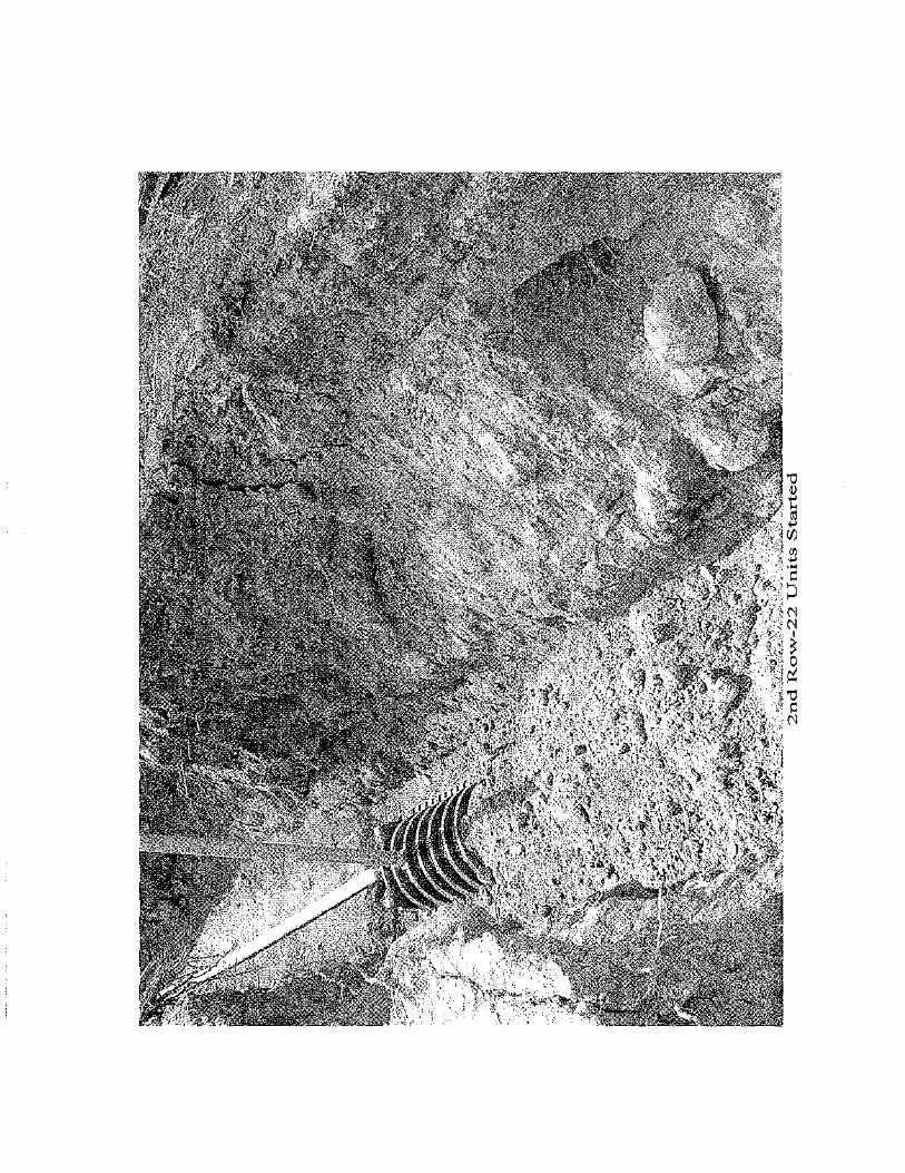
.5' t:'o,.,PCL-raz- r,P!,_,c. ;cOs~ 775 S::ao~ f?a"-' of' )·2. IJJA<->.o,cnz;,_
-;;;;_-,- /f;Ne 8=u Snc.-=
C=--:-;o--~--~--.~~~~~ Photo Documentation:
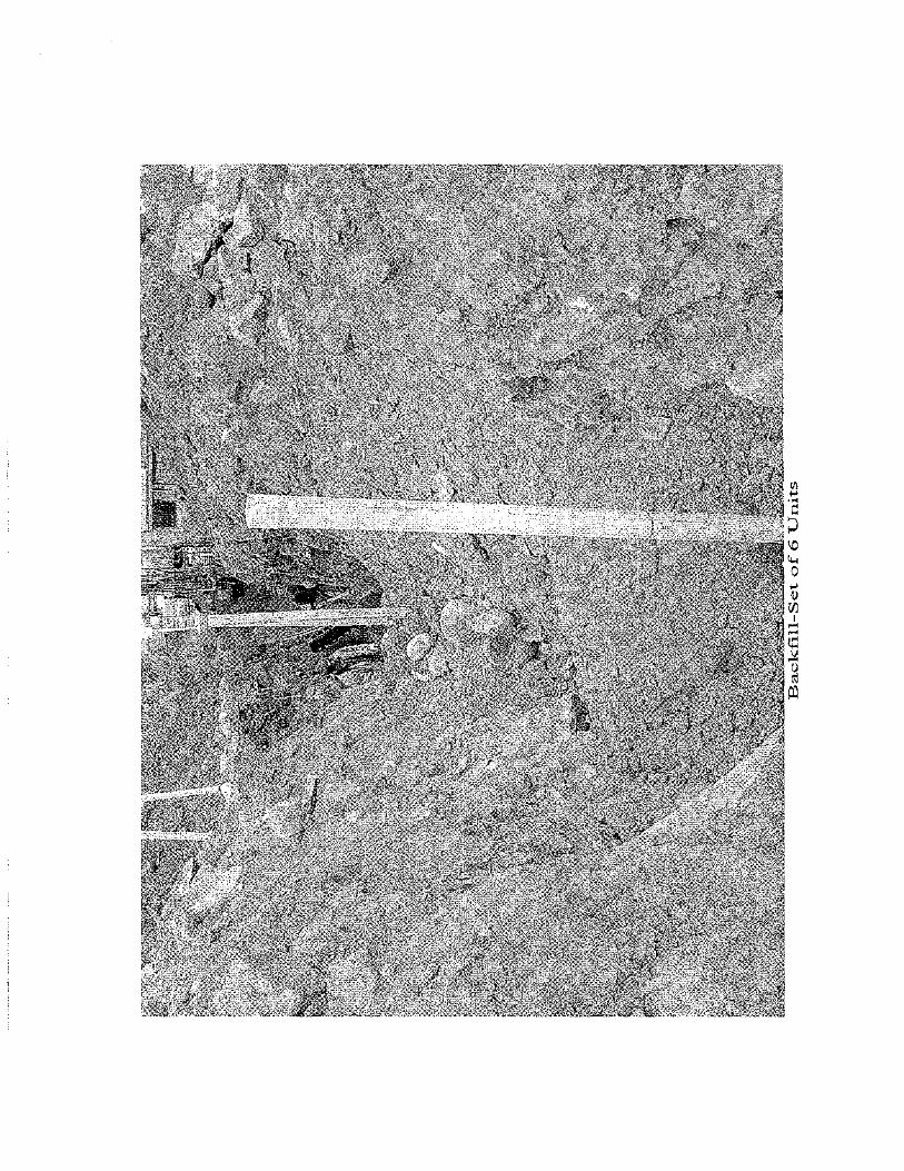
0 l'-6- 6<.--r-rJLJ.-iP· X> w & U;.n;>
--------------~-~~~~------~------
.


~-~-----------,-------------··-----~
All Employre-OW!l«! CornpOJ\y
High Country Engineering, Inc. 1517 Blake Avenue, Suite 101 Glenwood Springs, CO 81601
970 945-8676
-r;:._; !!me: ( ,J.rt)
?of..J7{1.Jv £9:7 ~'PEI-710f.J
- Cffl.ve,;-r h-r=
Field Re ort
- /loose L;ve B<.veeo'=-
:<"" ~ oF 22 :C<>FJ<--r=?ft_ U,;rro. 5~=
• 0,_rTl:4<---rt"'- /Tf.o. /r7r"7R:-Tei0 SCU:rr f7tT.:;a)Ac.- /Sec OF ~
;:r;._ /~ITI}f..... !~Al-L- /ec;v~ ~~ Ovaz_ up,-rj
~ h~-no/J u.J~ t\Y".t--""" 8o-u:.. .:r;:;~n._u._~ ~ 8l:.-rrFtu.--
Photo Documentation: (;Qq • ;1. I;! f?e.~. fJ.jl. UPon
0.50. ~, •• ;8~'-"
0.3 r - /--!ao~L..r.,e: :r"""-'11''"'
O.!>Jl 6rrt..vE3Uf" r.:..rc:z.
--------~---------------~-1
.--------- -~---------~--------_]

) ~
~ I I '
'• "· j
<;,y, ~b'" . ' '
• __ ,fitr_ - -;".
.. ··-:j'"''
,· ' '
,,_ -~1
' .,
\
. '


An Employee Ownod Company
High Country Engineering, Inc. 1517 Blake Avenue, Suite 101 Glenwood Springs, CO 81601
970) 945-8676
Field Re ort
fov,_ / Soec { Pr7 )
(), 5,-r~ '-"/ Ue.R( yf~u_. G::;;.oSy) ;:;:; -" A"-JU-- IV/L..- j ~~~ 6 P TI'"I-C c::::O ~_,..a=> JS:,.D,S . A W- E.s.r"'t:L7foJ VJC'a-~ .-<oy.::> IlvAC7I2 .. 1lTCJ::~
/,._~~/'A~ .A~ 8 /~ Ht.L.::::r:::>.
c:; D --o . C''-'TQ,(<----n:e_ f/1,_ ~ ,( ~ /IV /'-JC6 .5" }!f-<T tuUDL ?A'-'
/-.CLl.-~.5 A~ ro ~b7AL-I- Eia ... :;~ co~PL>J-r ...<~ P h~-->.-t<-
G't2-1c:>!J..X:> ;::r:e__ 701-&0tL.- /We=:> &~~7TO 0
- H'-'t<- ~v or II U,um- -Lo _ ) o ~/.,(U...~ k.....1k..n'"F"Il..L~
- L!/a-rr= ,£e L3~_,. /=17 ~ ( /?T!<Jtv?)
-------
Photo Documentation: :;:? . C)f'-f""Fi ~I :{"p~O<.J iL!ru..>
34-· /3?/<-ifPI '-'-J5· b<4<'F7...,_


No.IDaoro
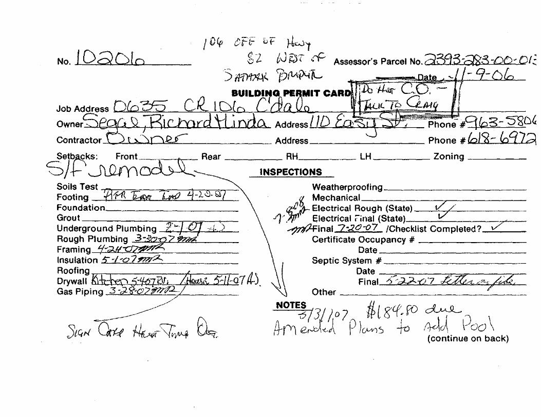
'-'-"'"-'-""""-'uyc-=-""-•. --"-'-~'_-Phone-#9 {Q 3- 'S"SD' -------Phone #&:,J<i$- ft:Bid,
de;tbf$Zks: f\ ()F;:~,.,.., ~ Rear _____ RH _____ LH ____ Zoning ____ _
0 +- . ~ UL..f 1 1 LJ~ INSPECTIONS
Soils Test ""f"f"r.,-:;;---;;=--,.,~:-;4CT'""',..,--'\ Footing !f3 f-1\ 'f;;;;;. :z:;;;1 + 2. '9. t~z Foundation _________ _
Grout --------;;c-r~..--,-Underground Plumbing z~/ ·OJ d.> Rough Plumbing 3~:i'o:a2ll'?;?;g Framing "(-;;w-o~ Insulation S-l-o7~ Roofing 4- . Drywall _J<ifCM>}·'M7~hQ(iS& 5"/f..a7 a.J. Gas P1p1ng ~~Qz?:§;Z-
~ 'StQrf~ ~7~ ~
Weatherproofing __________ _ g Mechanical ______ -r-------
ilf1"Jr Electrical Rough (State) --"t/:-7"------/j · .;IJI'" Electrical :Cinal (State) __ ____:_ ____ -r--~inal 7-.20·07 /Checklist Completed?__::\/_· __
Certificate Occupancy # --------Date __________ _
Septic System# __________ _
Date --:._.-. ---,----...,--~----c:-7"-Final ".> ·d,?-.-o7 l&ttt/'-c~-/4
Other--------------
NOTES , if, ( Cf fO ~ (}(Y) V:Jjo 7p )UA'}s g +a .~u\ \Joo \
(continue on back)
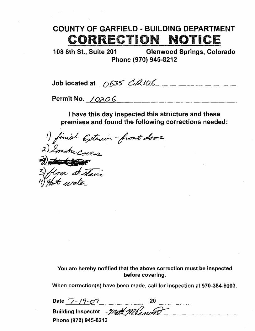
COUNTY OF GARFIELD - BUILDING DEPARTMENT
CORRECTION NOTICE 108 8th St., Suite 201 Glenwood Springs, Colorado
Phone (970) 945-8212
Job located at (J635' Cfi< IOC
PermitNo._/~0~~~0~6~---------------------------
I have this day inspected this structure and these premises and found the following corrections needed:
You are hereby notified that the above correction must be inspected before covering.
When correction(s) have been made, call for inspection at 970-384-5003.
Date 7-/9-o7 20 ____ _
Building Inspector -~~ Phone {970) 945-8212
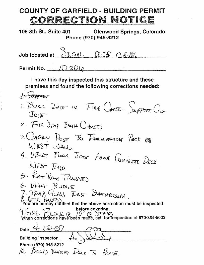
COUNTY OF GARFIELD - BUILDING PERMIT
CORRECTION NOTICE 108 8th St., Suite 401 Glenwood Springs, Colorado
Phone (970) 945-8212
Job I ocated at ----'='~'--"I..,_9=-u.ftlv=-___,Q;,.o...,~"",..."---'-C-"''I..'-'-''cw/fft""i,'-----Permit No. ---tLL..,.,.0"--"2-"'-"'0'-'(a¥-. __________ _
I have this day inspected this structure and these premises and found the following corrections needed:
cb~ 1. JJ._O(_f(. 'JQ_\~y I IJ..
TctF
z · Ftt.Ji. ~ ~ c~st<:5 ?. c~y ~'Sff' -rQ ~~f;Jk{ ?lllCI< aQT
LJiC3T w~. 4. U 14t=r tLSOIL 7Jousr ~vt: I> I'L
~W.CfLal: ~K bJ r ~( Ji-lff;.
;; · :K~+>r I?~ Tr~~':>~) b. Ut...U=r ~O(,_jc: 1. T~f>:. GLA~~ r:~x- /O~QiJ.i\.11 ' ~o~e<ne~rl>crlified that the above correction must be inspected
C( ;; ~L '12, OCIL rP ~~~r';:oS~i?J When corr~ns havlfbelm maae, call for mspection at 970·384·5003.
Building Inspector -~~~~~J.-f'---------Phone (970) 945·6212
;o, ~ H1Ji71'1!( J>iU._f(_ ""t. Jk,-J)r_
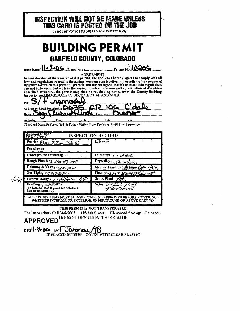
INSPECTION WILL NOT BE MADE UNLESS THIS CARD IS POSTED 0111 THE JOB
24 HOURS NOTICE REQUIRED FOK INSPECTIONS
BUILDING PERMIT GARFIELD COUNTY, COLORADO
Date Issuedl.J.!': •. ,':':O. .... Zoned Area ............................... Permit N: .. l.0.~4.~ .......... . AGREEMENT
In consideration of the issuance of this permit, the applicant hereby agree~ to comply with all la~-s and regulations related to the zoning, location; construction and erection of the proposed structure for which tbis permit is granted, and further agrees that if the above said regulations are not fully complied with in the zoning, location, erection and construction of the above described structure, the permit may then be revoked by notice from the County Building Inspector d}tiMEDIATELY BECOME NULL AND VOID.
u .. ,_f)Lf.J-'~ ·'1.41'oo~?--c ..... c--.-...---...-.--.----ti---Address or Legal Des ·gti!n.OJ ~i~~=~O~~C..~~~~~~==== '· ' Setbacks _____Enmt Side s· Tbis Card Must Be Posted So It I! Plainly Visible From The Street Until Finallnspeetlon.
~v , ,'T- INSPECTION RECORD Footing A~ r.;. z;... 4-2104'7 Driveway
Foundation
Underground Plumbing . .,_ ·' Insulation 5 -I ,<J7 ft?P Rough Plumbing 3 -~ D<YW•llt;-%1 \2>'-'L ,_~
Chimney & Vent 3-Zc~tn ~ Electric Final (by stm.Ww~ ?Lb/o?_ Gas Piping _s~;2J?-o7?.:; :;?P-...._ F;"'17-A?-c.7e== Electric Rough (By Sl "'~
Septic Final _kj
Framing lJ.~:ul-cJ!:!": Notes:~~g (fo indude Roof in pl~<ce and Windows aud Doon inslalll'd).
ALL LISTED ITEMS M!1!;;T BE INSPECTED AND APPROVED BEFORE COVERING~ WHETHER INTER!OR OR EXTERIOR, U!IIDERGROUND OR ABOVE GROUND.
TIDS PERMIT IS NOT TRANSFERABLE For Inspections Call384-5003 108 8th Street Glenwood Springs, Colorado
APPROVED DO NOT DESTROY THIS CARD
Datell~'f-~ Byr-:11'>1'\"""'• ~ IF PLAC£D'OuTSiD;:"C(fvJ~\\1TH CLEAR PLASTIC
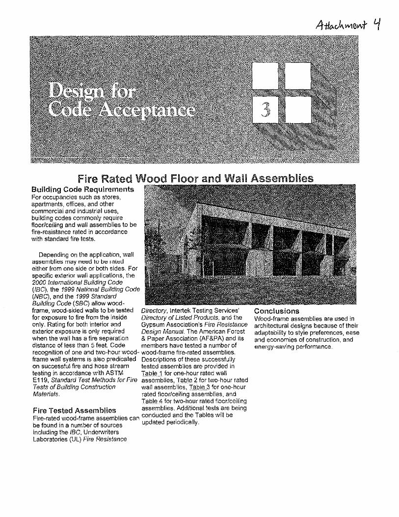
Fire Rated Wood Floor and Wall Assemblies Building Code Requirements For occupancies such as stores, apartments, offices, and other commercial and industrial uses, building codes commonly require floor/ceiling and wall assemblies to be fire·resistance rated in accordance with standard fire tests.
Depending on the application, waH assemblies may need to be 1 a ted either from one side or both sides. For specific exterior wall applications, the 2000 lntemational Building Code (IBC), the 1999 National Building Code (NBC), and the 1999 Sfandard Building Code (SBC) allow woodframe, wood·sided walls to be tested Directory, lntertek Testing Services' for exposure to fire from the inside Directory of Listed Products, and the only. Rating for both interior and Gypsum Association's Fire Resistance exterior exposure is only required Design Manual. The American Forest when the wall has a fire separation & Paper Association (AF&PA) and its distance of less than 5 feet. Code members have tested a number of recognition of one and two-hour wood- wood-frame fire-rated assemblies. frame walt systems is also predicated Descriptions of these successfully on successful fire and hose stream tested assemblies are provided in testing in accordance with ASTM l:?_b~_J for one-hour rated wall E119, Standard Test Methods for Fire assemblies, Table 2 for two-hour rated Tests of Bw1ding Construction wall assemblies, IID.J.LEL3 for one-hour Materials. rated floor/ceiling assemblies, and
Tsble 4 for two-hour rated floor/ceiling Fire Tested Assemblies assemblies. Additional tests _are being Fire-rated wood-frame assemblies can conddut cdted a_n~.th~ITables Will be be found in a number of sources up a e peno ICa Y· including the /BC, Underv~riters Laboratories (Ul) Fire Resistance
Conclusions Wood-frame assemblies are used in architectural designs because of their adaptability to style preferences, ease and economies of construction, and energy-saving performance.

-·-----.-------------
Table 1: One-Hour Fire-Rated Wall Assemblies
i r I U
i I i over studs II I II it i I
L Table?: Two-Hour F_ire-Rated _Loadbearing Wood-Fram.~ WaH Assemblies - J I Assemblies Rated From Both Sides I I Studs II Insulation II Sheathing on Both Sides II Fasteners II Details I 12•6@24"oo ] 5)';' mineral wool ba\ls (!Jf5ie· Type X Gypsum W~ttboa'CliHI -- ~~·y, .. 00 lypl; S drt<>·all screws@ 24" o.c. ~I WS021 I I 0!513' Typo X Gypsum Wallboard (H) ll2Y." 00 TypeS drywall screws@ 8" o.c.
H· app!1ed ho~wntall~· wtlh vertical joints over studs B- Bare layer ffieatlling F- face 1a1·er sheath·ng
"
~--···---
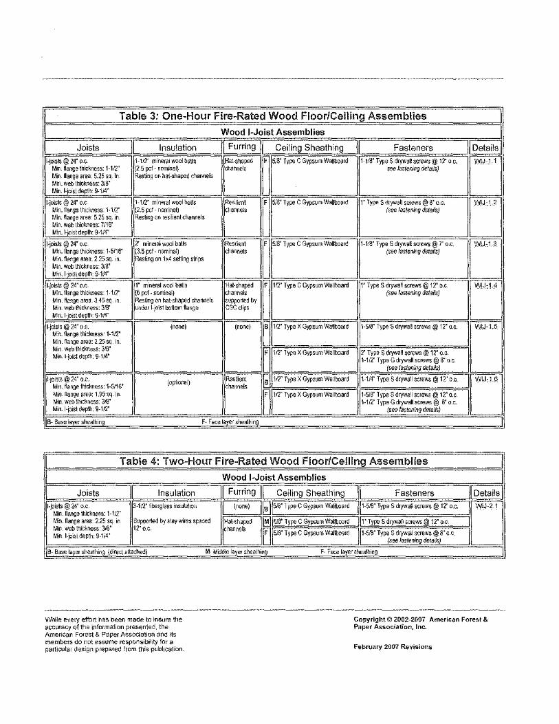
I Table 3: One-Hour Fire-Rated Wood Floor/Ceiling Assemblies I I Wood I~Joist Assemblies I I
~
II ~ . II Furrin9]1 II II Details I Joists Insulation Ceiling Sheathing Fasteners
1-joisls @ 24" o 1; H/2" mineral wool balls Hat-shaped
u 5/8" Type C Gyps~m Wallboard 1-l.'d" TypeS drywall screws@ 12' o c.
D Min. fianGe thickness: 1-112" (2 5 pel- nominal) channe!o see fastening rielarls} Min nanga area. 5.25 s~. In Resting on hal-shaped channels M1n. web thickness: 316' Min.l-jo11;l depth: 9-114"
1-joisls@ 24" o.c 1-1/2" min~ral wool balls ResiliMI
~ 5/8" Type C Gypsum WaUboam 1" TypeS drywall screwo@ 8" o.c.
D Min. nange \lidness. 1-112" (2.5 pel- nominal) cl,~nr.els (see fastening details) Min. nar.ge area- 5.25 sq. in. Reslir.g on res,lientct.annels M1n. web tl~ckness: 711\i" J Min. ).joist deplh: 9-114"
Hoists@ 24' o.c. l mineral wool balls Rw:i~nt
~ 5.'8" Type C Gypsum Wallboard 1-1.'3" TypeS drywall screws@ 7" o.c.
D Min. flange thickness: 1-5116" (3.5 pel· nominal) chflflr.els (see /astaning details) Min.flangearea:225sq 10, Resting on 1x4 selling strips M111. web thick~ess: 3.'8' M;n.l-:oistdep\!l: 9-1,14"
1-joists@ 24" o.c. 1" mineral wool balls 1-iat-ohaped
u 112" Type C Gypsum Wallboard 1' TypeS drywall screws@ 12" o.c
D M;n. llange thickness: 1-112" (6 pel. nominal) channels (see fastening detarls) M1n. fienge area. J 45 sq 1n. Resting on hat·shapsd channe!s SUP[X)~ed by M1n. web lhici<ness: 3!6" underl-joi:;t bottom ftaoge esc clips Min.l-'oistdeplh: 9-114"
1-joisls@ 24" o.c. (none)
D~ 112" Type X Gypsum Wallboard 1-51S" TypeS drywall screws@ 12' o.c.
D M'n. flange thdness· 1·112' Min. fiange art<a: 2.25 sq tn. Min. we\ll~ickness: 318"
1 12'ly~e X Gypsum Wallboard 2' TypeS drywall screws@ 1?." o.c. Min. 1-joisl dBplh. 9-114' 1-1/2" Type G dJYWall screws@ 8" o.c.
(seo fastMingd!ila!!s)
l·jOISIS@ 24" o.c. (opt1on~l)
Resilien; ~~~112' Type X Gypsum wa:lboard w-114" TypeS drywall screws@ 12" o.c. lld Min. ~ange thid\nr,ss: 1-5!16" chameis Min. llange area: 1.95 sq. in.
~ W' Type X Gypsum Wallboard 1·5!8" TypeS drywa'l screws@ 12" o.c.
Min. web lh1·;~ness 318' 1-11:2" Type G drywall screws@ 8" o.c. Min.l-jolsl depth. 9-112" (see fastenlng details)
B-- Base layer sheathing F· Face layer shaa!t1n
I Table 4: Two-Hour Fire-Rated Wood Floor/Ceiling Assemblies I I Wood I~Joist Assemblies I I Joists II Insulation II Furring II Ceiling Sheathing ]I Fasteners I [!)it~
I- joists@ 24' o.c 3-1!2" tiberglass insulallo;, I (non~) 11!]1518" l ype C Gypsum Wallboard ~~1-518" TypeS drywall screws@ 12" o.c.
ID Min flange lhickness: 1-1.'2" Min. nann a area. 2.25 sq 1n Supporl€d by slay wires spa::ed Hal-~haped IM]Isl8" Type C Gypsum Wallboard lit" TypeS drywall screws@ 12' o.c. I M1n web thicklless 318' 12"o.c. channels ~Ism· Type c Gypsum WaJtboarrl 11-5/8" TypeS drywall screws@ 8"c c. II Min 1-joisldepth:9·114''
(see f~srening details)
~~e la)'er sheathing (direct a!lached) M- Middi<Jiayer ~healhinq F- FEce layershe.alhir.g __j
V'lnile evel)' effort has be<1n made to insure the accuracy of the information presented. the Amencan Forest & Paper Assodat1on and its members do not assume responsibility for a particular design prepared from this publication.
Copyright© 2002-2007 American Forest & Paper Association, Inc..
February 2007 Revisions
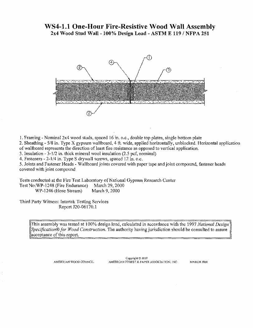
WS4-1.1 One-Hour Fire-Resistive Wood Wall Assembly 2x4 Wood Stud Wall -100% Design Load- ASTM E 119/ NFPA 251
1. Framing- Nominal 2x4 wood studs, spaced 16 in. o.c., double top plates, single bottom plate 2. Sheathing- 5/8 in. Type X gypsum wallboard, 4ft. wide, applied horizontally, unblocked. Horizontal application of wallboard represents the direction of least fire resistance as opposed to vettical application. 3. Insulation- 3-1/2 in. thick mineral wool insulation (2.5 pcf, nominal) 4. Fasteners- 2-1/4 in. TypeS drywall screws, spaced 12 in. o.c. 5. Joints and Fastener Heads- Wallboard joints covered \Vith paper tape and joint compound, fastener heads covered with joint compound
Tests conducted at the Fire Test Laboratory of National Gypsum Research Center Test No:WP~1248 (Fire Endurance) March 29,2000
WP-1246 (Hose Stream) March 9, 2000
Third Party Witness: Intertek Testing Services Report J20-06170.1
This assembly was tested at I 00% design load, calculated in accordance with the 1997 National Design] Specification® for Wood Construction. The authority having jurisdiction should be consulted to assure !I acceptance of this report.
Copyright© 2000 AMER!CAN WOOD COUNCIL AMERICAN FORES r & PAPER ASSOCIATION. INC MARCH 2000
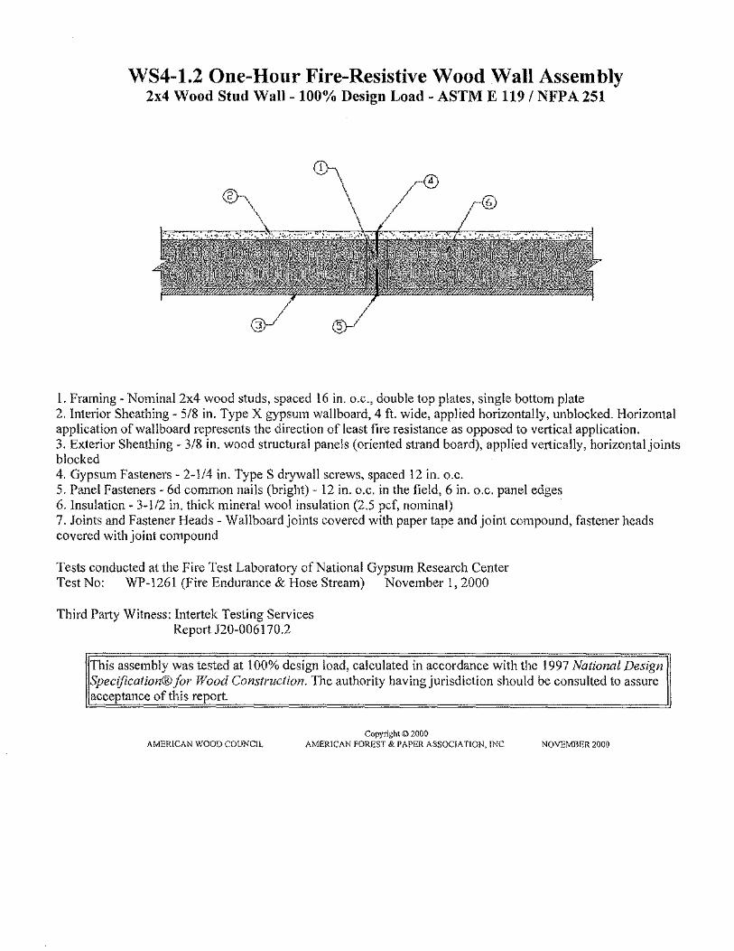
WS4-1.2 One-Hour Fire-Resistive Wood Wall Assembly 2x4 Wood Stud Wall- 100% Design Load- ASTM E 119/ NFPA 251
l. Framing~ Nominal2x4 wood studs, spaced 16 in. o.c., double top plates, single bottom plate 2. Interior Sheathing- 5/8 in. Type X gypsum wallboard, 4ft. wide, applied horizontally, unblocked. Horizontal application of wallboard represents the direction of least fire resistance as opposed to vertical application. 3. Exterior Sheathing- 3/8 in. wood structural panels (oriented strand board), applied vertically, horizontal joints blocked 4. Gypsum Fasteners~ 2-1/4 in. TypeS drywall screws, spaced 12 in. o.c. 5. Panel Fasteners- 6d common nails (bright)- 12 in. o.c. in the field, 6 in. o.c. panel edges 6.Insulation- 3-l/2 in. thick mineral wool insulation (2.5 pcf, nominal) 7. Joints and Fastener Heads- Wallboard joints covered with paper tape and joint compound, fastener heads covered with joint compound
Tests conducted at the Fire Test Laboratory of National Gypsum Research Center Test No: WP-1261 (Fire Endurance & Hose Stream) November 1, 2000
Third Party Witness: Intertek Testing Services Report 120-006170.2
This assembly was tested at 100% design load, calculated in accordance with the 1997 National Design Specification® for Wood Construction. The authority having jurisdiction should be consulted to assure acceptance of this report.
Copyright© 2000 AMERICAN WOOD COUNCIL AMERICAN FOREST & PAPER ASSOCI A TlON, ll\C NOVEMnER 2000
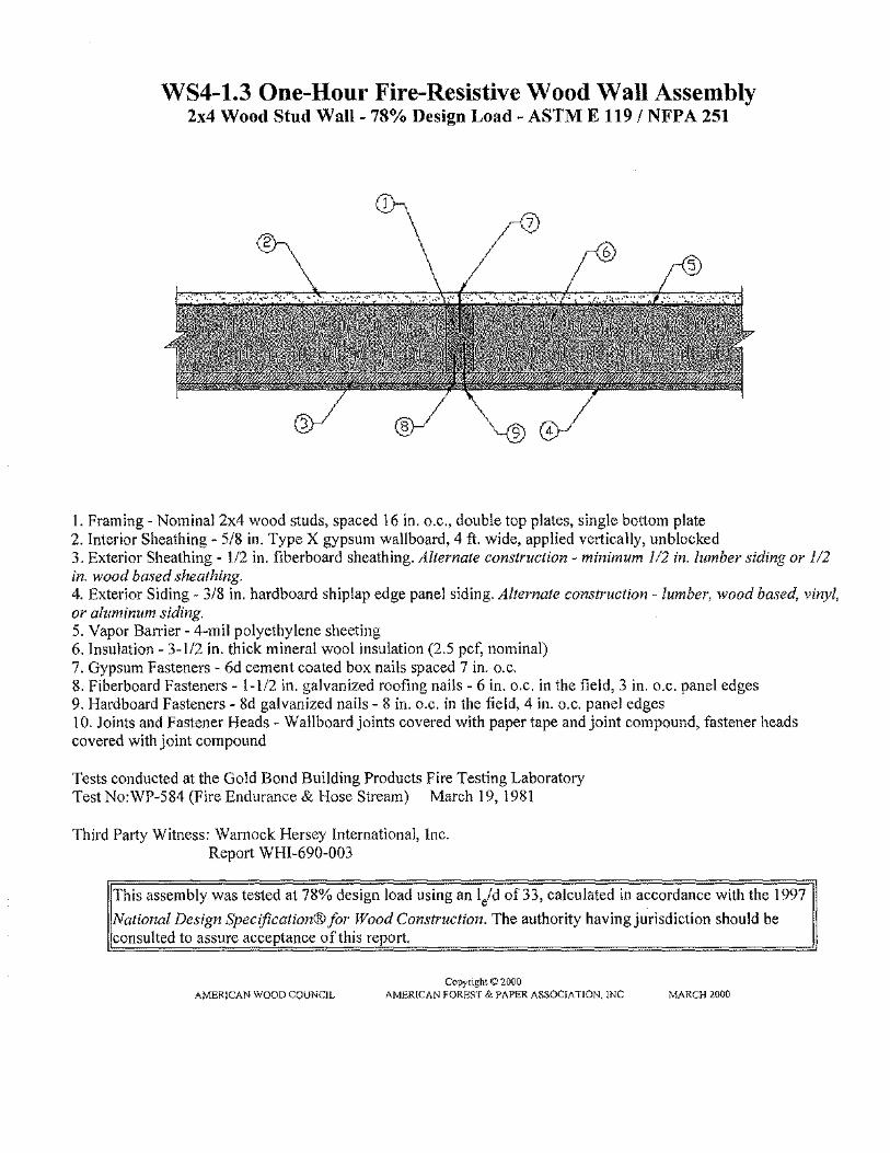
WS4-1.3 One-Hour Fire-Resistive Wood Wall Assembly 2x4 Wood Stud Wall-78% Design Load- ASTM E 119/ NFPA 251
1. Framing- Nominal2x4 wood studs, spaced 16 in. o.c., double top plates, single bottom plate 2. Interior Sheathing- 5/8 in. Type X gypsum wallboard, 4ft. wide, applied vertically, unblocked 3. Exterior Sheathing- 112 in. fiberboard sheathing. Alternate construction- minimum 1/2 in. lumber siding or 112 in. wood based sheathing. 4. Exterior Siding- 3/8 in. hardboard shiplap edge panel siding. Alternate construction - lumber, wood based, vinyl, or aluminum siding. 5. Vapor Barrier- 4-mil polyethylene sheeting 6. Insulation - 3-112 in. thick mineral wool insulation (2.5 pcf, nominal) 7. Gypsum Fasteners - 6d cement coated box nails spaced 7 in. o.c, 8, Fiberboard Fasteners- 1-1/2 in, galvanized roofing nails- 6 in, o,c, in the field, 3 in, o,c, panel edges 9, Hardboard Fasteners- 8d galvanized nails- 8 in, o.c. in the field, 4 in. o.c. panel edges 10. Joints and Fastener Heads- Wallboard joints covered with paper tape and joint compound, fastener heads covered with joint compound
Tests conducted at the Gold Bond Building Products Fire Testing Laboratory Test No:WP-584 (Fire Endurance & Hose Stream) March 19, 1981
Third Party Witness: Warnock Hersey International, Inc. Report WHI-690-003
This assembly was tested at 78% design load using an lid of 33, calculated in accordance with the 1997
National Desig11 Specification® for Wood Construction. The authority having jurisdiction should be consulted to assure acceptance of this report.
Copyright©200{) AMERICAN WOOD COUNCIL AMERICAN FOREST & PAPER ASSOCIATION, INC MARCH 2000

WS6-1.4 One-Hour Fire-Resistive Wood Wall Assembly 2x6 Wood Stud Wall-100% Design Load- ASTM E 119 I NFPA 251
1. Framing- Nominal 2x6 wood studs, spaced 16 in. o.c., double top plates, single bottom plate 2. Sheathing- 5/8 in. Type X gypsum wallboard, 4ft. wide, applied vertically. All panel edges backed by framing or blocking. 3. Insulation- R-19 fiberglass insulation 4. Fasteners- 2-1/4 in. TypeS drywall screws, spaced 12 in. o.c. 5. Joints and Fastener Heads- Wallboard joints covered with paper tape and joint compound, fastener heads covered with joint compound
Tests conducted at NGC Testing Services Test No:WP-1346 (Fire Endurance) August 22,2003
WP-1351 (Hose Stream) September 17, 2003
Third Party Witness: NGC Testing Services
IThis assembly was tested at 100% design load, calculated in accordance with the 1997 National Design Specification® for fYood Construction. The authority having jurisdiction should be consulted to assure acceptance of this report.
Copyright© 2003 AMERICAN WOOD COUNCIL AMERICAN FOREST & PAPER ASSOClATJON, lNC OCTOBER201J3

WS6-l.l One-Hour Fire-Resistive Wood Wall Assembly 2x6 Wood Stud Wall-100% Design Load- ASTM E 119/ NFPA 251
', _; : .. . . .,.... ~- ,. .
.. -•- ... ·
1. Framing- Nominal 2x6 wood studs, spaced 16 in. o.c., double top plates, single bottom plate 2. Sheathing- 5/8 in. Type X gypsum wallboard, 4ft. wide, applied horizontally, unblocked. Horizontal application of wallboard represents the direction of least fire resistance as opposed to vertical application. 3. Fasteners- 2-l/4 in. TypeS drywall screws, spaced 7 in. o.c. 4. Joints and Fastener Heads - Wallboard joints covered with paper tape and joint compound, fastener heads covered with joint compound
Tests conducted at the Fire Test Laboratory of National Gypsum Research Center TestNo:WP-1232 (Fire Endurance) September 16, 1999
WP-1234 (Hose Stream) September 27, 1999
Third Pat1y Witness: lntertek Testing Services Report )99-22441.2
This assembly was tested at 100% design load, calculated in accordance with the 1997 National Design Specification® for Wood Construction. The authority having jurisdiction should be consulted to assure acceptance of this report.
Cllpynght© l999 AMERICAN WOOD COUNCIL AMERICAN I'OREST & PAPER ASSOCIATION, INC OCTOBER \<199

WS6-1.2 One-Hour Fire-Resistive Wood Wall Assembly 2x6 Wood Stud Wall-100% Design Load- ASTM E 119/ NFPA 251
I. Framing- Nominal2x6 wood studs, spaced 16 in. o.c., double top plates, single bottom plate 2. Sheathing- 5/8 in. Type X gypsum wallboard, 4ft. wide, applied horizontally, unblocked. Horizontal application of wallboard represents the direction of least fire resistance as opposed to vertical application. 3. Insulation- 5-1/2 in. thick mineral wool insulation (2.5 pcf, nominal) 4. Fasteners- 2-1/4 in. TypeS drywall screws, spaced 12 in. o.c. 5. Joints and Fastener Heads- Wallboard joints covered with paper tape and joint compound, fastener heads covered with joint compound
Tests conducted at the Fire Test Laboratory of National Gypsum Research Center Test No:WP-1231 (Fire Endurance) September 14, 1999
WP-1230 (Hose Stream) August 30, 1999
Third Party Witness: lntcrtek Testing Services Report )99-22441.1
This assembly was tested at 100% design load, calculated in accordance with the 1997 National Design Specification®for Wood Construction. The authority having jurisdiction should be consulted to assure acceptance of this report.
Copyright© 1999 AMERICAN WOOD COUNCIL AMERICAN FOREST & PAPER ASSOCIATION, INC OCTOBER 1999

WS6-1.3 One-Hour Fire-Resistive Wood Wall Assembly 2x6 Wood Stud Wall- 100% Design Load- ASTM E 119/ NFPA 251
I. Framing -Nominal 2x6 wood studs, spaced 16 in. o.c., double top plates, single bottom plate 2. Interior Sheathing- 5/8 in. Type X gypsum wallboard, 4ft. wide, applied horizontally, unblocked. Horizontal application of wallboard represents the direction of least fire resistance as opposed to veJtical application. 3. Exterior Sheathing -7116 in. wood structural panels (oriented strand board), applied vertically, horizontal joints blocked 4. Gypsum Fasteners- 2-l/4 in. TypeS drywall screws, spaced 12 in. o.c. 5. Panel Fasteners- 6d common nails (bright)- 12 in. o.c. in the field, 6 in. o.c. panel edges 6. Insulation- 5-1/2 in. thick mineral wool insulation (2.5 pcf, nominal) 7. Joints and Fastener Heads- Wallboard joints covered with paper tape and joint compound, fastener heads covered with joint compound
Tests conducted at the Fire Test Laboratory of National Gypsum Research Center Test No: WP-1244 (Fire Endurance & Hose Stream) February 25, 2000
Third Party Witness: lntertek Testing Services Report 199-27259.2
This assembly was tested at 100% design load, calculated in accordance with the 1997 National Design Specification® for Wood Construction. The authority having jurisdiction should be consulted to assure I acceptance of this report.
Copyright :0 20CO AMERICAN WOOD COUNCIL AMERICAN FOREST & PAPER ASSOC!A TlON. INC MARC!·! 2000

WS6-1.5 One-Hour Fire-Resistive Wood Wall Assembly 2x6 Wood Stud Wall- 100% Design Load- ASTM E 119 I NFPA 251
l. Framing- Nominal 2x6 wood studs, spaced 16 in. o.c., double top plates, single bottom plate 2. Interior Sheathing~ 5/8 in. Type X gypsum wallboard, 4ft. wide, applied vertically. All panel edges backed by framing or blocking. 3. Exterior Sheathing- 3/8 in. wood structural panels (oriented strand board), applied vertically, horizontal joints blocked 4. Gypsum Fasteners- 2-l/4 in. TypeS drywall screws, spaced 7 in. o.c. 5. Panel Fasteners- 6d common nails (bright)- 12 in. o.c. in the field, 6 in. o.c. panel edges 6. Insulation- R-19 fiberglass insulation 7. Joints and Fastener Heads- Wallboard joints covered with paper tape and joint compound, fastener heads covered with joint compound
Tests conducted at the NGC Testing Services Test No: WP-1408 (Fire Endurance & Hose Stream) August 13, 2004
Third Party \Vitness: NGC Testing Services
This assembly was tested at 100% design load, calculated in accordance with the 200 I National Design Specification® fOr Wood Construction. The authority having jurisdiction should be consulted to assure acceptance of this report.
Copyright© 2004 AMERICAN WOOD COUNCIL AMERICAN FOREST & PAPER ASSOCIATION. 11\C AUGUST2004
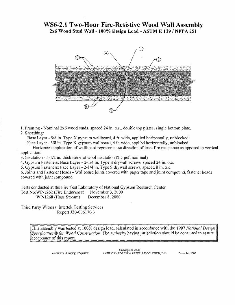
WS6-2.1 Two-Hour Fire-Resistive Wood Wall Assembly 2x6 Wood Stud Wall-100% Design Load- ASTM E 119 I NFPA 251
1. Framing- Nominal2x6 wood studs, spaced 24 in. o.c., double top plates, single bottom plate. 2. Sheathing:
Base Layer- 5/8 in. Type X gypsum wallboard, 4 ft. wide, applied horizontally, unblocked. Face Layer- 5/8 in. Type X gypsum wallboard, 4ft. wide, applied horizontally, unblocked.
Horizontal application of wallboard represents the direction of least fire resistance as opposed to vertical application. 3. Insulation- 5-1/2 in. thick mineral wool insulation (2.5 pcf, nominal) 4. Gypsum Fasteners: Base Layer- 2-1/4 in. TypeS drywall screws, spaced 24 in. o.c. 5. Gypsum Fasteners: Face Layer- 2-1/4 in. TypeS drywall screws, spaced 8 in. o.c. 6. Joints and Fastener Heads- Wallboard joints covered with paper tape and joint compound, fastener heads covered with joint compound
Tests conducted at the Fire Test Laboratory of National Gypsum Research Center Test No:WP-1262 (Fire Endurance) November 3, 2000
WP-1268 (Hose Stream) December 8, 2000
Third Party \Vitness: Intertek Testing Services Report )20-006170.3
This assembly was tested at 100% design load, calculated in accordance with the 1997 National Design Specification® for Wood Construction. The authority having jurisdiction should be consulted to assure acceptance of this report.
Copyright© 2000 AMERICAN WOOD COUNCIL AMERICAN FOREST & PAPER ASSOCIATION, INC December 2000

WIJ-1.1 One-Hour Fire-Resistive Ceiling Assembly Floora/Ceiling -100% Design Load -1 Hour Rating- ASTM E 119 I NFPA 251
1. Floor Topping (optional, not shown): Gypsum concrete, lightweight or normal concrete topping. 2. Floor Sheathing: Minimum 23/32 inch thick tongue-and-groove wood sheathing (Exposure l ). Installed per code requirements with minimum 8d common nails and glued to joist top flanges with AFG-01 construction adhesive. 3. Insulation: Minimum 1-1/2 inch thick mineral wool insulation batts- 2.5 pcf (nominal), supported by furring channels. 4. Structural Members: Wood l-joists spaced a maximum of24 inches on center.
Minimum 1-joist flange depth: 1-1/2 inches Minimum Hoist flange area: 5.25 inches2
Minimum I-joist web thickness: 3/8 inch Minimum 1-joist depth: 9-1/4 inches
'Jypes of Adhesives Used in Tested 1-.Joists Flange-to-Flange End·oint Flan~e-to-Web Joint Web-to-Web End'oint Resorcinol-Fommldehyde Phcnol-Resorcinol-Fonnaldehyde Pheno 1-Resorcinol-Formal de hyde
5. Furring Channels: Minimum 0.026 inch thick galvanized steel hat-shaped furring channels, attached perpendicular to l-joists using 1-5/8 inch long drywall screws. Furring channels spaced 16 inches on center and doubled at each wallboard end joint extending to the next joist. 6. Gypsum Wallboaa·d: Minimum 5/8 inch thick Type C gypsum wallboard installed with long dimension perpendicular to furring channels and fastened to each channel with minimum 1-118 inch long TypeS drywall screws. Fasteners spaced 12 inches on center in the field of the wallboard, 8 inches on center at wallboard end joints, and 3/4 inches from panel edges and ends. End joints of wallboard staggered. 7. Finish System (not shown): Face layer joints covered with tape and coated with joint compound. Screw heads covered with joint compound.
Fire Test conducted at Gold Bond Building Products Research Center Third Party Witness: Warnock Hersey International, Inc.
~ ~ I~
Ca<pet o Pod
~ Vinyl
IIC
- - -• This assembly may also be used 10" firc·mted roof.'cclling application, but only when constructed exactly as described_
1> STC and !IC va!ueo estimated by David L. Adams A"'ociate.>, Inc
Copyright© 2002. 2007 AMERICAN WOOD COUNCIL AMERICAN FOREST & PAPER ... SSOClA flON,lNC
IIC
'
February 9, 1990 Report No: WHJ-65!-03!1.1
Ca<pet P•d STC IIC
49" _59°
Fehruary/.007

WIJ-1.2 One-Hour Fire-Resistive Ceiling Assembly Floora/Cciling- 100% Design Load - 1 Hour Rating- ASTM E 119 I NFPA 251
1. Floor Topping (optional, not shown): Gypsum concrete, lightweight or normal concrete topping. 2. Floor Sheathing: Minimum 23/32 inch thick tongue-and-groove wood sheathing (Exposure 1 ). Insta!led per code requirements with minimum 8d common nails, and glued to joist top flanges with AFG-01 construction adhesive. 3. Insulation: Minimum 1-I/2 inch thick mineral wool insulation batts -2.5 pcf (nominal), supported by resilient channels. 4. Structural Members: Wood !-joists spaced a maximum of24 inches on center.
Minimum !-joist flange depth: 1-J/2 inches Minimum Hoist flange area: 5.25 inches2 Minimum }-joist web thickness: 7/16 inch Minimum J.joist depth: 9-1/4 inches
Tv es of Adhesives Used in Tested I~Joists. Fla11ge~to~Fla!!ge Endj9int I. Flangl!~to-Web Joint I Web-to-Web End'oint
Phenol-Resorcinoi-Fonnaldehyde I Phenol-Resorcinol-FOJmaldehyde I Phenol-Resorcinol-Fonnaldehyde
5. Resilient Channels: Minimum 0.019 inch thick galvanized steel resilient channels, attached perpendicular to !-joists using 1-5/8 inch long drywall screws. Resilient channels spaced 16 inches on center and doubled at each wallboard end joint extending to the next joist. 6. Gypsum Wallboard: Ivfinimum 5/8 inch thick Type C gypsum wallboard installed with long dimension perpendicular to resilient channels and fastened to each channel with minimum 1 inch long TypeS drywall screws. Fasteners spaced 12 inches on center in the field of the wallboard, 8 inches on center at wallboard end joints, and 3/4 inches from panel edges and ends. End joints of wallboard staggered. 7, Finish System (not shown): Face layer joints covered with tape and coated with joint compound. Screw heads covered with joint compound.
Fire Test conducted at Gold Bond Building Products Research Center Third Party Witness: Warnock Hersey International, Inc.
STC and IIC Sound Ratings for Listed Assembly
June 19, 1984 Report No: WHI-694-0 159
Without G sum Concrete With qypsum Concrete Cushioned Vinyl Carpet & Pad Cushioned Vinyl
STC I IIC STC IIC STC I Sib I 46" 51 b I 64b 60b I
"This assembly may also be used in a fire-rated ro.:>f.'Ce1!ing application, but only when constructed exactly as described.
b STC and flC values estimated by David L. Adams Asscciates,lnc
Copyright <0 2002, 2007 AMERICAN WOOD COUNCIL AMERICAN FOREST & PAPER ASSOCIATION, INC
IIC so"
Carpet & Pad STC 60b I
Februal)' 2007
IIC 65b

WIJ-1.3 One-Hour Fire-Resistive Ceiling Assembly Floora/CeiUng -100% Design Load -1 Hour Rating- ASTM E 119 I NFPA 251
I. Floor Topping (optiona~ not shown): Gypsum concrete, lightweight or normal concrete topping. 2. Floor Sheathing: Minimum 23/32 inch thick tongue-and-groove wood sheathing (Exposure l).lnstal!ed per code requirements. 3. Insulation: Minimum 2 inch thick mineral wool insulation batts- 3.5 pcf (nominal), supported by setting strip edges, friction-fitted between the sides of the !-joist flanges. 4. Structural Members: Wood !-joists spaced a maximum of24 inches on center.
Minimum I-joist flange depth: 1-5/16 inches Minimum l-joist flange area: 2.25 inches2
Minimum 1-joist web thickness: 3/8 inch Minimum !-joist depth: 9-1/4 inches
T es of Adhesives Used in Tested l~Joists LVL FlanJ:!;e Adhesive Flange~to-Web Joint Web-to-Web End'oint
Phenol~Resorcinol~Formaldeh_yde Emulsion Polymer Isocyanate Polyurethane Emulsion Polymer
5. Setting Strips: Nominal 1 x4 wood setting strips attached with 1-1/2 inch long drywall screws at 24 inches on center along the bottom flange ofl-joist creating a ledge to support insulation. 6. Resilient Channels: Minimum 0.019 inch thick galvanized steel resilient channels, attached perpendicular to l-joists using 1-7/8 inch long drywall screws. Resilient channels spaced 16 inches on center and doubled at each wallboard end joint extending to the next joist. 7. Gypsum Wallboard: Minimum 5/8 inch thick Type C gypsum wallboard installed with long dimension perpendicular to resilient channels and fastened to each channel with minimum 1-1/8 inch long TypeS drywall screws. Fasteners spaced 7 inches on center and 3/4 inches from panel edges and ends. End joints of wallboard staggered. 8. Finish System (not shown): Face layer joints covered with tape and coated with joint compound. Screw heads covered with joint compound.
Fire Test conducted at National Gypsum Testing Services, Inc. Third Party Witness: Underwriter's Laboratories, Inc.
STC and 1\C Sound Ratinr~s for Listed Assembly
September 28,2001 Report No: NC3369
Without (;ypsum Concrete With Gypsum Concrete Cushioned Vinyl Carpet & Pad Cushioned Vinyl
STC I nc STC IIC STC 51 b I 46 b 52 I 66 60 b I
• This aoo.ambly may also be used in a firc·rated roof/ceiling application, but only when constructed exactly a:; des<;ribed_
b STC ~nd IlC values estimated by Dav1d 1.. Adams Assoctales. Inc
Copyright© 2002, 2007 AMERICAN WOOD COUNCIL AMEfllCAl'i fOREST & PAPER ASSOC!ATION,lNC
nc 48b
Carpet & Pad STC 60b I
Fcbm~ry 2007
nc 60b

WJJ-1.4 One-Hour Fire-Resistive Ceiling Assembly Floora/Ceiling- 100% Design Load- 1 Hour Rating- ASTM E 119/ NFPA 251
1. Floor Topping (optional, not shown): Gypsum concrete, lightweight or normal concrete topping. 2. Floor Sheatlting: Minimum 23/32 inch thick tongue-and-groove wood sheathing (Exposure 1 ). Installed per code requirements with minimum 8d common nails. 3.lnsulation: Minimum I inch thick mineral wool insulation batts- 6 pcf(nominal) with width equal to the on-center spacing of the !-joists. Batts installed on top of furring channels and under bottom flange ofl-joists with the sides butted against support clips. Abutted ends ofbatts centered over furring channels with batts tightly butted at all joints. 4. Structural Members: Wood !-joists spaced a maximum of24 inches on center.
Minimum !-joist flange depth: 1-1/2 inches Minimum 1-joist flange area: 3.45 inchcs2 Minimum !-joist web thickness: 3/8 inch Minimum !-joist deptl1: 9-1/4 inches
T les of Adhesives Used in Tested 1-Joists Flan~e-to-Flan,ge Endioint Flange-to-Web Joint Web-to-Web End.ioint
Phenol-Resorcinol-Formaldeh ·de Phenol-Resorcinol-Formaldehyde Resorcinol-Formaldehyde
5. Furring Channels: Minimum 0.0 I 9 inch thick galvanized steel hat-shaped furring channels, attached perpendicular to !-joists spaced 24 inches on center. At channel splices, adjacent pieces overlapped a minimum of6 inches and tied with a double strand ofNo. 18 gage galvanized steel wil·e at each end of the overlap. Channels secured to 1-joists with Simpson Type CSC support clips at each intersection with the !-joists. Clips nailed to the side ofi-joist bottom flange with one 1-1/2 inch long No.1 J gage nail. A row of furring channel located on each side of wallboard end joints and spaced 2.25 inches from the end joint ( 4.5 inches on center). 6. Gypsum Wallboard: Minimum l/2 inch thick Type C gypsum wallboard. Wallboard installed with long dimension perpendicular to furring channels and fastened to each channel with minimum 1 inch long TypeS drywall screws. Fasteners shall be spaced 12 inches on center in the field of the wallboard, 6 inches on center at wallboard end joints, and 3/4 inches from panel edges and ends. End joints of wallboard continuous or staggered. Fm· staggered wallboard end joints, furring channels extend a minimum of 6 inches beyond each end of the joint. 7, Finish System (not shown): Face layer joints covered with tape and coated with joint compound. Screw heads covered with joint compound.
May 11, 1983 Fire Test conducted at Underwriter's Laboratories, Inc Third Party Witness: Underwriter's Laboratories, Inc. Report No: UL R10371-1
STC and IIC Sound Ratin s for Listed Assembl Without Gypsum Concrete With Qypsum Concrete
Cushioned Vinyl Carpet & Pad Cushioned Vinyl C_jlrpet & Pad STC I uc STC uc STC I IIC STC I . I . 46 I 68 51 I 47 50 I
'This a"'cmbly may also be uoed in a firc·rated rooficeiling r.pplioallon, but only ;.·hen c;()P.Sintc!ed eMc!ly as described
Copyri~>hl © 2002, 2007 AMEJUCAN WOOD COUNCIL AMERICAN FOREST & PAPER ASSOCIATION, INC Februaty 2007
uc 73
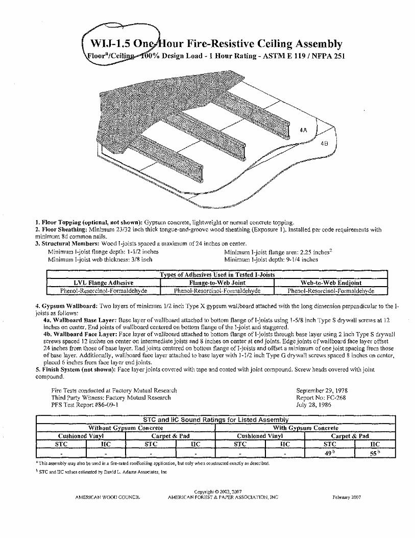
our Fire-Resistive Ceiling Assembly ,...-TOO% Design Load ~ 1 Hour Rating - ASTM E 119 I NFP A 251
1. Floor Topping (optional, not shown): Gypsum concrete, lightweight or nonnal concrete topping. 2. :Floor Sheathing: Minimum 23132 inch thick tongue-and-groove wood sheathing (Exposure 1). Installed per code requirements with minimum Sd common nails. 3. Structural Members: Wood !-joists spaced a maximum of24 inches on center.
Minimum 1-joist flange depth: 1-112 inches Minimum I-joist flange area: 2.25 inches2
Minimum !-joist web thickness: 3/8 inch Minimum !-joist depth: 9-\/4 inches
Types of Adhesives Used in Tested 1-Joists LVL Flan}!c Adhesive
Pheno !-Resorcinol-Formaldehyde I Flane;e-to-Web Joint I Phenol-Resorcinol-Formaldehyde
Web-to-Web End"oint Phenol-Rcsorcinol-Pormaldehvde
4. Gypsum Wallboard: Two layers of minimum 1/2 inch Type X gypsum wallboard attached with the long dimension perpendicular to the!joists as follows:
4a. Wallboard Base Layer: Base layer of wallboard attached to bottom flange ofl-joists using 1-5/8 inch Type S drywall screws at 12 inches on center. End joints of wallboard centered on bottom flange of the !-joist and staggered. 4b, Wallboard Face Layer: Face layer of wallboard attached to bottom flange ofl-joists through base layer using 2 inch TypeS drywall screws spaced 12 inches on center on intermediate joists and 8 inches on center At end Joints. Edge joints of wallboard face layer offset 24 inches from those of base layer. End joints centered on bottom flange of !-joists and offset a minimum of one joist spacing from those of base layer. Additionally, wallboard face layer attached to base layer with 1-112 inch Type G drywall screws spaced 8 inches on center, placed 6 inches from face la)'cr end joints.
5. Finish System (not shown): Face layer joints covered with tape and coated with joint compound. Screw heads covered with joint compound.
Fire Tests conducted at Factory Mutual Research Third Pmty Witness: Factory Mutual Research PFS Test Report #86-09-1
~ S1 ; and IIC ; for Listed~
Pnd ; I Vinyl
STC I!C S1 I!C STC
"This assembly may also be medIna fire-rated roollceJlmg appllcauon, bul only wlwn COi>shuc!ed exac1ly as de sen bed_
b STC and l!C values eslimatcd by David L. Adam~ Asso<::Jales, Inc
Copyttghl © 2002,2007 AMERICAN WOOJJ COUNCIL A(>iliRlC'\N FOREST & PAJ"ER ASSOCIATlON,lNC
I!C
September 29, 1978 Report No: FC-268 July 28,1986
S" 49b
; Pnd
February 2007
fl(
ssh

WIJ-1.6 One-Hour Fire-Resistive Ceiling Assembly Floora/Ceiling ~ 100% Design Load -1 Hour Rating- ASTM E 119 I NFPA 251
l. Floor Topping (optional, not shown): Gypsum concrete, lightweight or normal concrete topping. 2. Floor Sheathing: Minimum 23/32 inch thick tongue-and-groove wood sheathing (Exposure 1 ). Installed per code requirements with minimum 8d common nails. 3. lnsu lation (optiona~ not shown): Insulation fitted between !-joists supported by the resilient channels. 4. Structural Members: Wood !-joists spaced a maximum of24 inches on center.
Minimum 1-joist flange depth: 1-5/16 inches Minimum l-joist flange area; 1.95 inches2
Minimum !-joist web thickness: 3/8 inch Minimum l-joist depth: 9-112 inches
LVL Flan e Adhesive Phenol-Rcsorcinol-Fonnaldeh de
T es of Adhesives Used in Tested 1-Joists Flan e-to-Web Joint
Emulsion Pol mer Isoc anate Web-to-Web End'oint
Emulsion Pol mer !soc anate
5. Resilient Channelsb: Minimum O.DJ 9 inch thick galvanized steel resilient channel attached pe!Vendicular to the bottom flange of the !-joists with one 1-1/4 inch drywall screw. Channels spaced a maximum of 16 inches on center [24 inches on center when I-joists arc spaced a maximum of 16 inches on center]. 6. Gypsum Wa\Jboard: Two layers of minimum 1/2 inch Type X gypsum wallboard attached with the long dimension perpendicular to the resilient channels as follows:
6a. Wallboard Base Layer: Base layer of wallboard attached to resilient channels using 1-1/4 inch Type S drywall screws at 12 inches on center. 6b. Wallboard F"ace Layer: Face layer of wallboard attached to resilient channels through base layer using 1-5/8 inch Type S drywall screws spaced J 2 inches on center. Edge joints of wallboard face layer offset 24 inches from those of base layer. Additionally, wallboard face layer attached to base layer with 1-1/2 inch Type G drywall screws spaced 8 inches on center, placed 6 inches from face layer end joints.
7. Finish System (not shown): Face layer joints covered with tape and coated with joint compound. Screw heads covered with joint compound.
Fire Test conducted at National Research Council of Canada Report No: A-4440.1 June 24, 1997
STC and I!C Sound Ratin s for Listed Assembl Without G sum Concrete WithG sum Concrete
Cushioned Vinyl Car et & Pad Cushioned Vin I c" et & Pad STC IIC STC uc STC IIC STC IIC
lwith Insulation 59 50 55° 68 ° 65 51 63' 65°
~ithout Insulation - - 54 68 - - 58' 55'
"This assembly may ~l•o be used m a flre-rared roof.'ce1ling applicmion, but only when constn\Ctecl exac!ly as destribed.
bl)irec! a11achment of gypsum wallboard in lieu ofaHachmcnt to resilient channels'' typically deemed ae<eptable. When gypsum wallboard is directly attached to the ).joists, the wallboard shm1ld
be instalkcl with loug dimension perpendicular to th~ ].joists ""d insulation sho~ld not be s11ppo11ed l>y rhe wallboard
c STC and !lC values estimated by David L. AdTims Assod~tes, Inc
Copyright <D 2002, 2007 AMERICAN WOOD COUNCIL AMERICAN FOREST & PAPER ASSOCIATION, INC Febnmy 2007

WIJ-2.1 Two-Hour Fire-Resistive Ceiling Assembly Floora/Ceiling -100tt;o Design Load- 2 Hour Rating- ASTM E 119/ NFPA 251
I. Floor Topping (optional, not shown): Gypsum concrete, lightweight or normal concrete topping. 2. Floor Sheathing: Minimum 23/32 inch thick tongue-and-groove wood sheathing (E;-.posure 1). Installed per code requirements. 3. Insulation: Minimum 3-l/2 inch thick unfaced fiberglass insulation fitted between I-joists supported by stay wires spaced 12 inches on center. 4. Structural Members: Wood !-joists spaced a maximum of24 inches on center.
Minimum l-joist flange depth: 1-112 inches Minimum 1-_ioist flange area: 2.25 inches2 Minimum J-joist web thickness: 3/8 inch Minimum !-joist depth: 9-1/4 inches
Types of Adhesives Used in Tested !-.Joists LVL Flan~e Adhesive Flan~e-to-Web Joint Web-to-Web End'oint
Phenol-Resorcinol-F onnaldehyde Pheno 1-Resorcinol-F ormaldehvde Phenol-Resorcinol-!' ormaldehyde
5. Furring Channels: Minimum 0.0179 inch thick galvanized steel hat-shaped furring channels, attached perpendicular to !-joists using 1-5/8 inch long drywall screws. Furring channels spaced 16 inches on center (furring channels used to support the second and third layers of gypsum wallboard). 6. Gypsum Wallboard: Three layers of minimum 5/8 inch Type C gypsum wallboard as follows:
6a. Wallboard Base Layer: Base layer of wallboard attached to bottom flange of !-joists using 1-5/8 inch Type S drywall screws at 12 inches on center with the long dimension of wallboard perpendicular to !-joist. End joints of wallboard centered on bottom t1ange of the 1-joist and staggered from end joints in adjacent sheets. 6b. Wallboard Middle Layer: Middle layer of wallboard attached to furring channels using I inch TypeS drywall screws spaced 12 inches on center with the long dimension of wallboard perpendicular to furring channels. End joints staggered from end joints in adjacent sheets. 6c. Wallboard Face Layer: Face layer of wallboard attached to furring channels t11rough middle layer using 1-5/8 inch Type S drywall screws spaced 8 inches on center. Edge joints of face layer of wallboard offset 24 inches from those of middle layer. End joints of face layer of wallboard staggered with respect to the middle layer.
7. Finish Syst~-m (not shown): Face layer joints covered with tape and coated with joint compound. Screw heads covered with joint compound.
Fire Test conducted at Gold Bond Building Products Research Center Third Party Witness: PPS Corporation
STC and IJC Sound Ratings for Listed Assembly
December 16, 1992 Report No; #92-56
WithoutGv sum Concrete With Gypsum Concrete Cusbioned Vinvl Carpet & Pad Cushioned Vinvl
STC IIC STC IIC STC
- - 49b 54b 52 b
'Tim assembly may ulso be used Ln a fir~-ra1ed rooFicctlmg applicatiOn, bn1 only when con,lructcd exactly ~s dc;cnbed
b STC and liC values eSiimated by David L. Adams Associates, h1c
Copyright)) 2002, 2007 AMERICAN WOOD COUNCIL AMERICAN FOREST & PAPER ASSOCIATION, INC
uc 46b
Carpet & Pad STC szb I
Fcbmary 2001
IIC 60 b

Parcel Detail Page 1 of3
Garfield County Assessor/Treasurer
Parcel Detail Information
A$S:CS:sor!Tre_as_ur~.r .Prop~rty Sr;arcl). I As_s~§.S.QLS.u_bstl_Qg~ry I A$SCSS:Ql: SaJes_S_~arch ClGrk .& .R9c9nJer .. E~~-e.p6qn__S_car~h
B_a,s.~c. BujlQing __ Chm:~cteris.~iq; I Tax Information
P~x~~LQ_~t<!il I V£-ttlJ.~_PYJ?~_U S.akiill~tall I R~lii.d~tJJiai!CQmm~r~i_!;l.U!P-PI9Yem~lllP_~taU kan<\ !le\lli! I PbotoZ!1l!1ll>
I Tax Area II Account Number II Parcel Number II Mill Levy I
I on II R011534 II 239328300013 II 63.377 I
Owner Name and Mailing Address
!SEGAL, RICHARD M & LINDA
110635 COUNTY ROAD 106
!cARBONDALE, CO 81623
Legal Description
ISECT,1WN,RNG:28·7·88 DESC: LOT 5&11 I IL YING s OF DRGW ROW & N OF ROAR. I IFORK RlV BK:0486 PG:0833 BK: 1627 I IPG:633 RECPT:660935 BK: 1121 PG:949 I IRECPT:542888 BK:0799 PG:0530 I /BK:0794 PG:0729 I
Location
I Physical Address: l/635 106 COUNTY RD CARBONDALE!
Subdivision: I
Land Acres: 114.1
Land Sq Ft: 110
Section II Township II Range I 28 I 7 II 88 I
http :1 I www, garcoact ,cotn/ assessor/parcel ,asp ?ParcelN umber"" 23 9 3 283000 13 11/8/2006

Parcel Detail Page 2 of 3
Property Tax Valuation Information
Actual Value II Assessed Value I
Land: II 23o,oooll 18,3101
Improvements: II !49,43011 11,8901
Total: II 379,43oll 30,2001
Sale Dale: 119/30/2004
Sale Price: 11419,000
Basic Building Characteristics
Number of Residential 1 Buildings:
Number of Commllnd 0 Buildings:
I Residential Building Occurrence 1 Characteristics I
I TOTAL HEATED AREA: jj1,680 I
I ABSTRACT CODE·IISINGLE F AM.RES-
. lMPROVEMTS I I ARCHITECTURAL STYLE: I/1-STRY/BSM I
I EXTERIOR WALL: 1/VINYL I I ROOF COVER: 1/PREFAB MET I
I ROOF STRUCTURE: jjGABLE I INTERIOR WALL: jjDRYWALL I
f'LOOR: jjCARPET I HEATING FUEL: IlGAS I HEATING TYPE: jjHT WTR RAD I
STORIES: jjsTORIES 1.0 I BATHS: I 2
I ROOMS: I 5
I UNITS: j1
I BEDROOMS:/ 3
I YEAR BUILT: jj1930 I
Tax Information
TaxYear II Transaction Type II Amount
http://www .garcoact.comfassessor/parce!.asp ?ParcelN umber=2393283000 13 1118/2006
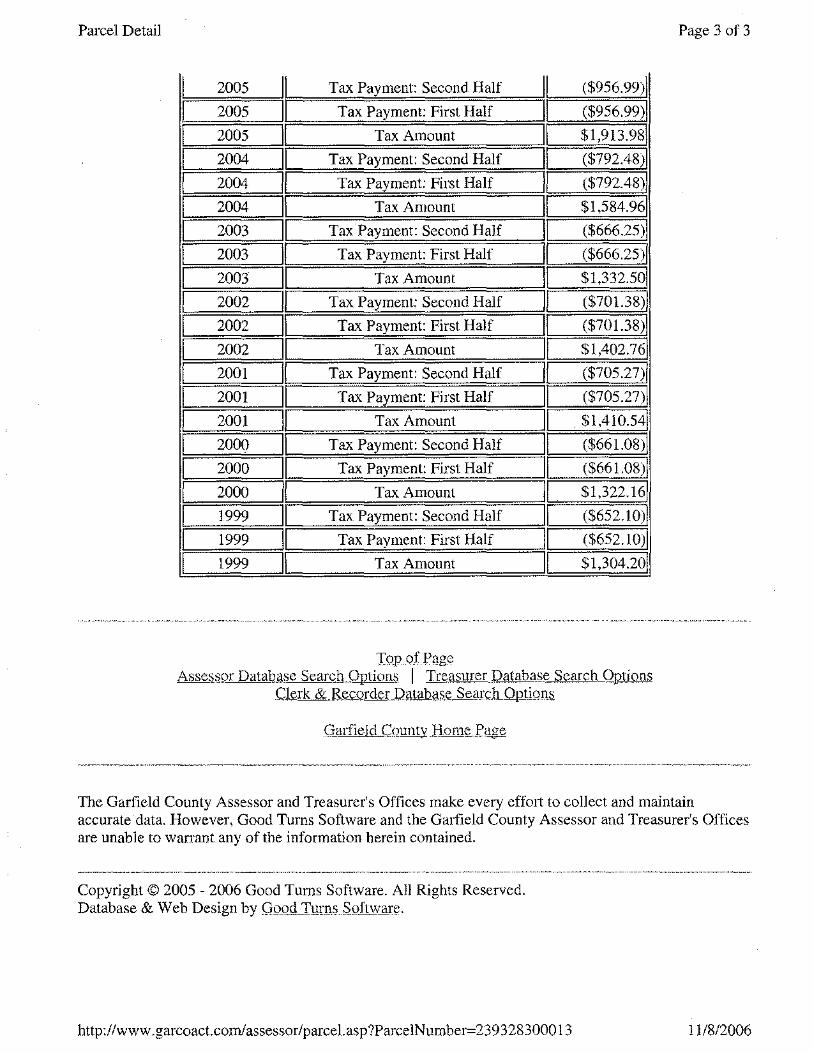
Parcel Detail
I 2005 II Tax Payment: Second Half I ($956.99)1
I 2005 II Tax Payment: First Half ($956.99)1
I 2005 II Tax Amount $1,913.981
I 2004 II Tax Payment: Second Half ($792.48)1
I 2004 II Tax Payment: First Half II ($792.48)1
I 2004 II Tax Amount II $1,584.961
I 2003 II Tax Payment: Second Half II ($666.25)1
I 2003 II Tax Payment: First Half II ($666.25)1
I 2003 II Tax Amount II $1,332.501
I 2002 II Tax Payment: Second Half II ($70!.38)1
I 2002 II Tax Payment: First Half II ($701.38)1
I 2002 II Tax Amount II $1,402.761
I 2001 II Tax Payment: Second Half II ($705.27)1
I 2001 II Tax Payment: First Half II ($705.27)1
I 2001 II Tax Amount II . $1,410.541
I 2000 II Tax Payment: Second Half II ($661.08)1
I 2000 II Tax Payment: First Half II ($661.08)1
I 2000 II Tax Amount II $1,322.161
I 1999 II Tax Payment: Second Half II ($652.10)1
I 1999 II Tax Payment: First Half II ($652.10)1
I 1999 II Tax Amount II $1,304.201
To_p of Page Asse~;;;pr Datab.m;e Sean:;1tQntion!); I Tre,.otsurer_Pataba_t;~ Search Options
.C15'rk &.R~cqrderJ.)A.!i:!hi<!-$.e Se~_rc_h_Qu_li9.11::t
Gurfield CQunty_}lom~ .. Pli¥e
Page 3 of 3
The Garfield County Assessor and Treasurer's Offices make every effmt to collect and maintain accurate data. However, Good Turns Software and the Garfield County Assessor and Treasurer's Offices are unable to wanant any of the information herein contained.
Copyright© 2005 - 2006 Good Turns Software. All Rights Reserved. Database & Web Design by Q.opd T!l[Q-5 .. S.QftWJlJJ~.
http :1 /www. garcoact.com/ assessor/parcel. asp ?ParcelN urn ber= 23 9 3 283000 13 11/8/2006

/
''!Ill ' ! . !! ., !
·ijl!l f ~ II 'I' ! l:
m~ 'lii!i i ' ~ ~ tlpl i
•il Hf~-~ I1Jlf ! 'I
j'21) l.l' '
li! j-gh- !!ji! f ' ~~~~ !! !l f i '•~>'
i~~ I'll! f
~~! ;!!'i ' lidl I i'l ••. 1 1!!!.
0
' '
- ,f3j~ ji! 1 itO !l·i ·~ ·~ ,. t· I r " ~~ ~ ~n r g :~:~ H' II' • ~'" ii' ~i [ I
'lit ~h~i I . I , !' .. ; ~ .n ~ :,1,11!1 ' • i'1"j £ ~ til l
'-L • • ii' • " ! I ,, f ' ,., ' I'' ' I ~ . ' ! !i . '
' ··~ollf.'l."l&' •• m:~.&i£'.'1~00.,, .. ,.,,,~·J.?.!::~,r:.~....:a:w::==" .. '
a ... " r .. ;, ,;:
c z m
~ lg ·'
0
r· ~ ' 0
' ' ''
!
' '
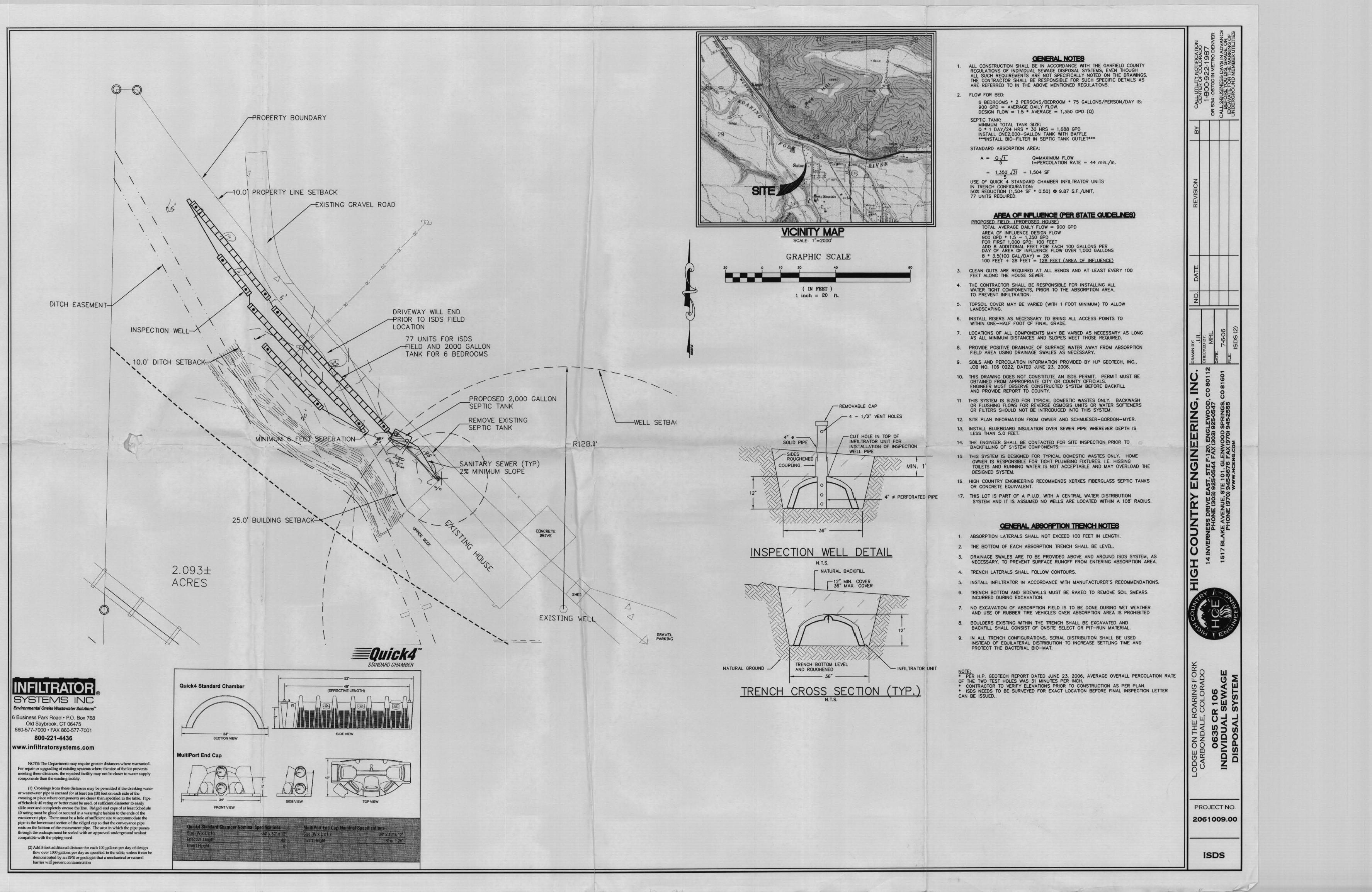
ROPERTY BOUNDARY
\ 10.0 PROP RTY LINE SETBACK
DITCH EASEMENT
'
\ \ ~~· ·. \ \ .
·. \ \ .
\
. \ \ .
. \ \ .
INSPECTION WELL
', 10.0' DITCH
' ' ' ' ' ' ' ' -' ' ' ' ' ' ' '
2.093± ACRES
' ' ' ' ' ' ' ' ' ' ' ' ' ' ' ' ' ' 25.0' BUILDING SETBACK'
Qulck4 Standard Chamber
Business Park Road • P.O. Box 768 Old Saybrook, CT 06475
860·577·7000 ·FAX 860-577·7001
800-221-4436
NOm: The Department may requiTe gTeater di5tances where warranted. For repair or upgrading of existing B)'1>t2ms where the size of tile Jot prevents meeting these distance&, the repaired facility may oot beclo6er to water supply compononls than the existing facility.
(1) CfOS!iings from these distances may be permitted if the drinking water or wastewater pipe is erv:ased for at least ten (10) feet on eadlside of the CTO!il>ing or place where c;umporH'lts arecklseT dum specified in the table. Pipe of Schedule 40 rating or better must be used, of suf&ient diameter to easily slide over and oompletelyencase the line. Ridged end cap5 of at least Schedule 40 rating must be glued or secured in a watertight fashion to the ends of the encasement pipe. There must be a hole of su£li,;:ient·siu- to IICCOD'Imodat:e the pipe in the lowennost section of the ridged cap so that tile conveyance pipe rests on the bottom of the enciiSE!nlcnt pipe. ~ area in which the pipe passes through the endcaps must be se~~led with Ill\ approved Wlderground eealant oompahble with the piping used.
(2) Add 8 feet additional distance lor each 100 gallons per day of design flow over 1000 gallons per day as specified in the table, unless it can be demonstraiL'd by an RPE or geologist that a mechanical Of" natural barrier will p~ent contamination
MultiPort End Cap
,.. SIDE VIEW
FRONT VIEW
XISTING GRAVEL ROAD
.... ,; I /' .... ,
I J
I I
' '
DRIVEWAY WILL END RIOR TO ISDS FIELD
LOCATION
77 UNITS FOR ISDS IELD AND 2000 GALLON
TANK FOR 6 BEDROOMS
/
---
/ PROPOSED 2,000 GALLON SEPTIC TANK
/
............ \ \ ' . ' '>~ ... .,
REMOVE EXISTING SEPTIC TANK
""-..
"' -...'\-~-:SANITA~Y SEWER (TYP) % MINI~UM SLOPE
/ ~ +
CONCRETE DRIVE
--
R\2.8.0'
SHEO
I I
\ ?
\
\ ',, ',...-"\ ' . .,.-- ...........
\ ', ' '
C) EXISTING
' ' .... _ ...__ --- . ---.. -- --I \
STANDARD CHAMBER
(EFFECTIVE LENGTH)
TOP VIEW
--'---WELL SETBAI
.d <l
GRAVEL PARI<ING
GRAPHIC SCALE 20 0 10 20 40 ..
I r---- liiiiiiiiiil~l iiiiiiiiiiiiiiil~~~ ( IN FEET )
1 inch = 20 ft.
4". ---... SOLID PIPE
REMOVABLE CAP
4 - 1/2" VENT HOlES
'-"' '-"'""" 0/:~'>/ SIDES Y:<'((~ RDYGHENaS
CUT HOLE IN TOP OF INFILTRATOR UNIT FOR INSTALLAllON OF INSPECTION WELL PIPE
·~ COUoUNG-
'* 12"
I
f---- 36" ----1
INSPECTION WELL DETAIL
/
N.T.S,
NATURAL BACI<CFILL
/
12" MIN. COVER 36" MAX .. COVER
/
TRENCH BOTTOM LEVEL
•
1'
AND ROUGHENED
f---- 36" ----1 INFILTRATOR UNIT
TRENCH CROSS SECTION N.T.S.
(TYP.)
1.
2.
3.
4.
5.
6.
7.
8.
9.
10.
11 .
12.
13.
14.
15.
ALL CONSTRUCTION SHALL BE IN ACCORDANCE 1NITH THE GARFIELD COUNTY REGULATIONS OF INDIV1DUAL SEWAGE DISPOSAL SYSTE~S. EVEN THOUGH ALL SUCH REQUIREMENTS ARE NOT SPECIFICALLY NOTED ON THE DRAWINGS. THE CONTRACTOR SHALL BE RESPONSIBLE FOR SUCH SPECIFIC DETAILS AS ARE REFERRED TO IN THE ABO\IE MENTIONED REGULATIONS.
FLOW FOR BED:
6 BEDROOMS • 2 PERSONS/BEDROOM • 75 GALLONS/PERSON/DAY IS: 900 GPO = AVERAGE DAILY FLOW. DESIGN FLOW = 1.5 ' AVERAGE = 1,350 GPO (0)
SEPTIC TANK: MINlt.4UM TOTAL TANK SIZE: Q * 1 OAY/24 HRS • 3D HRS = 1,688 GPO INSTALL ONE2,000-GALLON TANK WITH BAFFLE •••INSTALL 810-FILTER IN SEPTIC TANK OUTLET•••
STANDARD ABSORPTION AREA:
Q=MAXIMUM FLOW t=PERCOLA TION RATE ,. 44 min./ln.
• 1,350 J3i 1,504 Sf 5
USE OF QUICK 4 STANDARD CHAMBER INflLTRATOR UNITS IN TRENCH CONFIGURATION: 50~ REDUCTION (1,504 SF • 0 .50) 0 9.87 S.F./UNIT, 77 UNITS REQUIRED.
/IlEA OF IN'! • ft'Qf <PER srAJE 01 m ., PROPOSED FIELD: (PRQPOSED HOUSE)
TOTAL AVERAGE DAILY FLOW - 900 GPO AREA OF INFLUENCE DESIGN FLOW 900 GPO • 1.5 IZ 1,350 GPO FOR FIRST 1,000 GPO: 100 FEET ADD 8 ADDillONAL FEET FOR EACH 100 GALLONS PER DAY OF AREA OF INFLUENCE FLOW OVER 1,000 GALLONS B * 3.5(100 GAL/DAY) '"' 28 100 FEE'r + 28 FEET "' 128 FEET (AREA OF INFLUENCE)
CLEAN OUTS ARE REQUIRED AT ALL BENDS AND AT LEAST EVERY 100 FEET ALONG THE HOUSE SEWER.
THE CONTRACTOR SHALL BE RESPONSIBLE FOR INSTALLING ALL WATER TIGHT COt.4PONENTS, PRIOR TO THE ABSORPTION AREA, TO PREVENT INFILTRATION.
TOPSOIL COVER MAY BE VARIED (Vt'llH 1 FOOT MINIMUt.4) TO ALLOW LANOSCAPING.
INSTALL RISERS AS NECESSARY TO BRING ALL ACCESS POINTS TO 'MTHIN ONE-HALF FOOT Of FINAL GRADE.
LOCATIONS Of All COt.lPONENTS !.lAY BE VARIED AS NECESSARY AS LONG AS All MINIMUM DISTANCES AND SLOPES MEET THOSE REQUIRED.
PRO'v1DE POSITIVE DRAINAGE OF SURFACE WATER AWAY FROM ABSORPTION FIELD AREA USING DRAINAGE SWALES AS NECESSARY.
SOILS AND PERGOLA liON INFORMATION PROVIDED BY H.P GEOTECH, INC., JOB NO. 106 0222, OA TED JUNE 23, 2006.
THIS DRAWING DOES NOT CONSTITUTE AN ISDS PERMIT, PERMIT MUST BE OBTAINED FROM APPROPRIATE CITY OR COUNTY OFFICIALS. ENGINEER MUST OBSERVE CONSTRUCTED SYSTEM BEFORE BACKFILL AND PROVIDE REPORT TO COUNTY.
THIS SYSTEM IS SIZED FOR TYPICAL DOMESTIC WASTES ONLY. BACKWASH OR FLUSHING FLOWS FOR REVERSE OSMOSIS UNITS OR WATER SOFTENERS OR FILTERS SHOULD NOT BE INTRODUCED INTO THIS SYSTE~ .
SITE PLAN INFORMATION FROM O'M'IER AND SCHMUESER-GORDON-MYER.
INSTALL BLUEBOARD INSULATION OVER SEWER PIPE WHEREVER DEPTH IS LESS THAN 5.0 FEET.
THE ENGINEER SHALL BE CONTACTED FOR SITE INSPECTION PRIOR TO BACKfiLUNG OF S'rSTEM COMF :)NENTS.
THIS SYS1H1 IS DESIGNED FOR TYPICAL DOMESTIC WASTES ONLY. HOME O'NNER IS RESPONSIBLE FOR TIGHT PLUMBING FIXTURES. LE. HISSING TOILETS AND RUNNING WATER IS NOT ACCEPTABLE AND MAY 0\IERLOAD THE DESIGNED SYSTEM.
16. HIGH COUNTRY ENGINEERING RECOMMENDS XERXES FIBERGLASS SEPTIC TANKS OR CONCRETE EQUIVALENT.
17. THIS LOT IS PART OF A P.U.D. WITH A CENTRAL WATER DISTRIBUTION SYSTEM AND IT IS ASSUMED NO WELLS ARE LOCATED WITHIN A 108' RADIUS.
1. ABSORPTION LATERALS SHALL NOT EXCEED 100 FEET IN LENGTH.
2. THE BOTIOM OF EACH ABSORPTION TRENCH SHALL BE LEVEL
3. DRAINAGE SWALES ARE TO BE PROVIDED ABOVE AND AROUND ISDS SYSTEM, AS NECESSARY, TO PRE\IENT SURFACE RUNOFF FROM ENTERING ABSORPTION AREA.
4. TRENCH LATERALS SHALL FOLLOW CONTOURS.
5. INSTALL INFILTRATOR IN ACCORDANCE WITH MANUFACTURER'S RECOMMENDATIONS.
6. TRENCH BOTIOM AND SIDEWALLS MUST BE RAKED TO REMO\IE SOIL S~EARS INCURRED DURING EXCAVATION.
7. NO EXCAVATION Of ABSORPTION FIELD IS TO BE DONE DURING WET WEATHER AND USE Of RUBBER liRE VEHICLES OVER ABSORPTION AREA IS PROHIBITED
8. BOULDERS EXISTING 'NITHIN THE TRENCH SHALL BE EXCAVATED AND BACKFILL SHALL CONSIST OF ONSITE SELECT OR PIT-RUN MATERIAL
9. IN ALL TRENCH CONFlGURA TIONS, SERIAL DISTRIBUTION SHALL BE USED INSTEAD OF EQUILATERAL DISTRIBUTION TO INCREASE SETlUNG TIME AND PROTECT THE BACTERIAL 810-MAT.
~ • PER H.P. GEOTECH REPORT DATED JUNE 23, 2006, AVERAGE OVERALL PERCOLATION RATE OF THE TWO TEST HOLES WAS 31 MINUTES PER INCH. • CONTRACTOR TO VERIFY ELEVATIONS PRIOR TO CONSTRUCTION AS PER PLAN. • ISDS NEEDS TO BE SURVEYED F'OR EXACT LOCATION BEFORE FINAL INSPECTION LETTER CAN BE ISSUED ..
z 0 iii ~ a::
...J .., ,.., • ~
...J ;..:: 0:: • ::i'
~ ~ u 0
"' @
Q -If) 'I' 0 ,... If)
ij c
PROJECT NO.
2061009.00
1505

'
--------------------------~----~--------------------~~-=
\ \ '\
\ ROPERTY BOUNDARY \
\ \
\ \
\ \
\
" \ ,, ,, ,, \\ 10.0 PROP RTY LINE SETBACK
DITCH EASEMENT
. \ \ .
·. \ \ .
~
. \ \ ·.
\
. \ \ .
·. \ \ .
INSPECTION WELL
•
2.093± ACRES
25.0'
Qulck4 Standard Chamber
Business Park Road • P.O. Box 768 Old Saybrook. CT 06475
86D-577-7000 • FAX 860-577-7001
800·221-4436 I wv•w .i nflltrat:orsystems .com
NOI'B: The l:leptlrtmmt may treqoire greater diftarK'ft where wamu'llied. For repllir or 11pgradin@; of exi&dl1g syatms where the lizlo of the lot preven1:5 meeting these diltancel. the ~ facility may not be cbet' 10 wale~" supply CDIJ]~ d\an the existing lacility.
(1) c~ from lhesedistances may be permittEd if the drinkingwat.?r orw85tewaler pipe is~ b-at least IE!n (10) feet: on each side of the ~or pbao where companents are ckJser than specified in the table. Pipe of Scheel We 4D rating or betler must be used, of sufficimtdiarneter 1o easily slide over and c::omple!ely ~ the line. Ridged end caps of at leallt Schedule 40 Bting must be glued or secured ina walett:ightfashlon ID the ends of the enca8ell'lellt pipe. 1bere mWit be a hoJe of sufficient ~ize lo II£'COI11ll'IOdte the pipe in the lowermost section of the ridged cap 90 that the conveyltflCe pipe te$18 an the bot:tom of the eocuement pipe. The area in which the pipe paB9e11
through the endcapa must be lle8led wilh an approved undet'gf'Ound sealant oompatible with the piping ueed.
(2) Add 8 feet additional dislanre lor e6Ch 100 gallons per dl}' of deiign fiQw ~1000 ga.11ons per day as specified in tbe lahle, unles6 itCIIII be demonstr.llied by m RPii or gt'l?k:lgist that 11. mechankal or natural banieT will' prevent contaminatilln
MuHIPort End Cap
X/STING GRAVEL ROAD
? /
/ /
/ / DRIVEWAY WILL END
RIOR TO ISDS FIELD LOCATION
77 UNITS FOR ISDS IELD AND 2000 GALLON
TANK FOR 6 BEDROOMS
-------
----- ---- ----/
_,/ PROPOSED 2,000 GALLON ,.. SEPTIC TANK
/ /
,.. REMOVE EXISTING SEPTIC TANK --- -' ' ' R128.0'
I
\,
\
~~~"-oSANITAFIY SEWER (TYP) % MINI~UM SLOPE
I I
~~ +
'·< I CCJNCRETf:
I ' I ', I ', . I ', \
' \ I ', I ., \ I \ ',, I . , I \ ', I \ ' . __.-'\ .... I - ', I c:::- \ ', I \ ' I ', I ', \ ___1 \ ........
~Ouick4~ STANDARD CHAMBER
1-------- ... - ------1 (EFFECTIVE LENGTH)
.... ' ' ' '
DRIVE
' ' ' EXISTING W't~
'
-
' .., ..,
'---WELL SETBA<
"'
L:l <J
GRAYEL PARKING
GRAPHIC SCALE 20 0 " 20 .. .. ~-- I I I I I
( IN FEET ) 1 inch = 20
4". --., SOUD PIPE
'....y '-V~'v ~~~ SIDES / '"<.,'-:: 7..,::Y_>;: RD\)GHEN.O
'~ cou.UNG -
'* 12"
I
ft.
REI.10VABLE CAP
4 - 1/2" VENT HOLES
CUT HOLE IN TOP OF INFILTRATOR UNIT fOR lfNSTALLATION Of INSPECTION 'tWELl PIPE
1----- 36" ------1
INSPECTION WELL DETAIL N.T.S.
NATURAL BACKFILL
INFILTRATOR UNIT
TRENCH CROSS SECTION (TYP.) N.T.S.
1.
2.
3.
4 .
5.
6.
7.
8.
9.
10.
All CONSTRUCTION SHALL BE IN ACCORDANCE 'MTH lHE GARFIELD COUNTY REGULATIONS Of INDIV1DUAL SEWAGE DISPOSAL SYSlHAS, E'vt:N THOUGH All SUCH REOUIREt.4ENTS ARE NOT SPECIFICALLY NOTED ON THE DRA'MNGS. THE CONTRACTOR SHALL BE RESPONSIBLE FOR SUCH SPECIFIC DETAILS AS ARE REFERRED TO IN 11-iE ABOVE MENTIONED REGULA liONS,
FLOW FOR BED:
6 BEDROOMS • 2 PERSONS/BEDROOM " 75 GALLONS/PERSON/DAY IS; 900 GPO :::::: AVERAGE DAILY FLOW. DESIGN FLOW = 1.5 • AVERAGE "" 1,350 GPO (0)
SEPTIC TANK: MINit.AUM TOTAL TANK SIZE: 0 • 1 DAY/24 HRS ,• .30 HRS = 1,688 GPO INSTALL ONE2,000-GALLON TANK WITH BAFFLE """INSTALL 810-FlLTER IN SEPTIC TANK OUTLET•••
STANDARD ABSORPTION AREA:
Q::::MAXIMUM FlOW t=PERCOLA TION RATE ::: 44 min./ln .
= 1,350 J31 : 1,504 Sf 5
USE Of QUICK 4 STANDARD CHAMBER INFJL TRATOR UNITS IN lRENCH CONFIGURATION: 50% REDUCTION (1,504 SF • 0.50) 0 9.87 S.F./UN1T, 77 UNITS REQUIRED.
AfEA OF lf'Uft!Qf (fB STAlE CU!R tel PROPOSED FIELD: (PROPOSED HOUSE)
TOTAL AVERAGE DAILY FLOW = 900 GPO AREA OF INFLUENCE DESIGN FLOW 900 GPO • 1.5 :::::: 1,350 GPO FOR FIRST 1,000 GPO: 100 FEET ADD 8 ADDITIONAL FEET FOR EACH 100 GALLONS PER DAY OF AREA OF INFLUENCE FLOW OVER 1,000 GALLONS 6 • 3.5(100 GAL/DAY) = 28 100 FEE'r + 28 FEET = 128 FEET (AREA Of INFLUENCE)
CLEAN OUTS ARE REQUIRED AT AU BENDS AND AT LEAST EVERY 100 FEET ALONG THE HOUSE SEWER.
THE CONTRACTOR SHALL BE RESPONSIBLE FOR INSTALLING All WATER TIGHT COMPONENTS, PRIOR TO THE ABSORPTION AREA, TO PREVENT INFILTRATION.
TOPSOIL COVER MAY BE VARIED ('MTH 1 FOOT MINIIAUM) TO ALLOW LANDSCAPING.
INSTALL RISERS AS NECESSARY TO BRING ALL ACCESS POINTS TO WITHIN ONE-HALF FOOT OF FINAL GRADE.
LOCATIONS OF ALL COMPONENTS MAY BE VARIED AS NECESSARY AS LONG AS All MINIMUM DISTANCES AND SLOPES MEET THOSE REQUIRED.
PROVIDE POSITIVE DRAINAGE OF SURFACE WATER AWAY FROM ABSORPTION FIELD AREA USING DRAINAGE SWALES AS NECESSARY.
SOILS AND PERCOLATION INF0Rt.4ATION PROVIDED BY H.P GEOTECH, INC., JOB NO. 106 0222, DATED JUNE 23, 2006.
THIS DRAWING DOES NOT CONSTITUTE AN ISDS PERMIT. PERMIT MUST BE OBTAINED FR~ APPROPRIATE CITY OR COUNTY OFFICIALS. ENGINEER MUST OBSERVE CONSTRUCTED SYSTEM BEFORE BACKFILL AND PROIJIDE REPORT TO COUNTY.
11. THIS SYSlEM IS SIZED FOR TYPICAL DOMESTIC WASTES ONLY, BACKWASH OR FLUSHING FLOWS FOR REVERSE OSMOSIS UNITS OR WATER SOFTENERS OR FILTERS SHOULD NOT BE INTRODUCED INTO THIS SYSTEM.
12. SITE PLAN INFORMATION FROM OWNER AND SCHMUESER-GORDON-MYER.
1.3. INSTALL BLUEBOARD INSULATION OVER SEWER PIPE 'M-IEREVER DEPTH IS LESS THAN 5.0 FEET.
14, THE ENGINEER SHALL 6E CONTACTED FOR SITE INSPECTION PRIOR TO BACl(FI'.UNG OF" <:; YSTEM COV PONENTS.
15. lHIS SYSTEM IS DESIGNED FOR TYPICAL DOMESTIC WASTES ONLY, HOME OWNER IS RESPONSIBLE FOR TIGHT PLUMBING FIXTURES, I.E. HISSING TOILETS AND RUNNING WATER IS NOT ACCEPTABLE AND MAY OVERLOAD THE DESIGNED SYSTEM.
16, HIGH COUNTRY ENGINEERING RECOMMENDS XERXES FIBERGLASS SEPTIC TANKS OR CONCRETE EQUIVALENT.
17. THIS LOT IS PART OF A P.U.D. WITH A CENTRAL WATER DISTRIBUTION SYSTEM ANO IT IS ASSUMED NO WELLS ARE LOCATED WITHIN A 108' RADIUS.
1. ABSORPTION LATERALS SHALL NOT EXCEED 100 FEET IN LENGTH.
2. THE BOTTOM OF EACH ABSORPTION TRENCH SHALL BE LEVEL.
.:5. DRAINAGE SWALES ARE TO BE PROVIDED ABOVE AND AROUND ISDS SYSTEM, AS NECESSARY, TO PREVENT SURFACE RUNOFF FROM ENTERING ABSORPTION AREA.
4 . TRENCH LATERALS SHALL FOLLOW CONTOURS.
S. INSTALL INFILTRATOR IN ACCORDANCE Will-i MANUFACTURER'S RECOMMENDATIONS,
6 . TRENCH BOTTOM AND SIDEWALLS MUST BE RAKED TO REMOVE SOIL SMEARS INCURRED DURING EXCAVATION.
7. NO EXCAVATION OF ABSORPTION FIELD IS TO BE DONE DURING WET WEATHER AND USE Of RUBBER TIRE VEHICLES OVER ABSORPTION AREA IS PROHIBITED
8, BOULDERS EXISTING WITHIN THE TRENCH SHALL BE EXCAVATED AND BACKFILL SHALL CONSIST OF ON SITE SELECT OR PIT-RUN MATERIAL.
9 , IN All lRENCH CONFIGURA TlONS, SERIAL DISTRIBUTION SHALL BE USED INSTEAD OF' EQUILATERAL DISTRIBUTION TO INCREASE SETlLING TIME AND PROTECT THE 6ACTERIAL BIO- ~AT.
AVERAGE OVERALL PERCOLATION RATE
INSPECTION LETTER
• 0 z -~ ~ z -0:: LIJ LIJ z -~ z LIJ
~
N --i 0 C)
§~ ~~
-2 -110 0 C)
~~ I
§ (f) 0 (f)
"Pi ca ~s 8!:~ ~~ ~~~ ~~ ~~~ ~~ ~~~ ~ 2 wr-- ::»S
Ill z Ill 1- cz ~z z 1110
~~ 111:1: :J IIIII.
0 ~ 0 ~ Ill
"' -• Ul :c - -~ -:c
PROJECT NO.
2061009.00
ISDS