Embed Size (px)
Citation preview
Produc
tInformationIZT C3040
Satellite Link Simulator
REV.4.00|01.02.2020
World leading RF quality
Frequency conversion from input to output
100 MHz instantaneous bandwidth
Simulation of uplink, payload and downlink
Accurate synchronization of multiple IZT C3040
Spectrum display with automatic C/N control
2
The IZT C3040 Satellite Link Emulator provides
a cost-eff ective, time-saving total solution with
exceptional functionality for satellite and aircraft
RF link testing.
Accurate, comprehensive and repeatable sim-
ulation of uplink, payload and downlink in the
IZT C3040 let system engineers create realistic
scenarios for testing their product in a labora-
tory environment.
Key applications include:Satellite (LEO, GEO, MEO)
UAV
Modem, transmitter and receiver testing
Telemetry tracking system and range verif cation
Training and education
3
IZT C3040 | Satellite Link Simulator
Overview
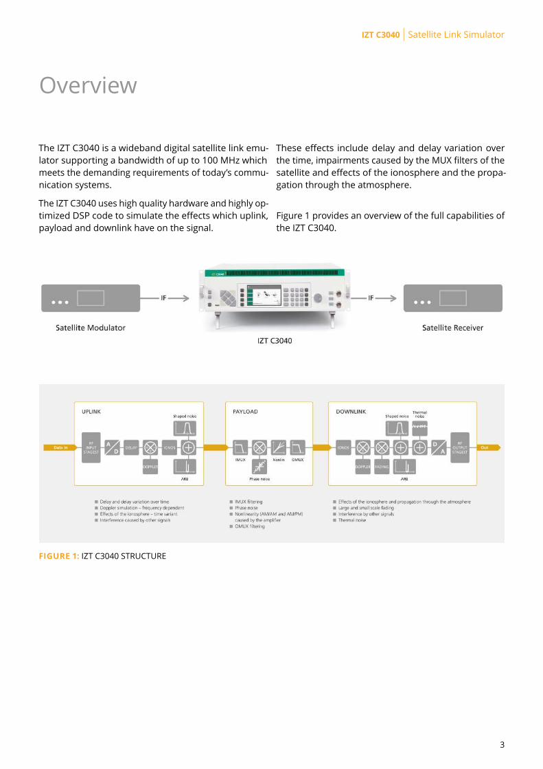
The IZT C3040 is a wideband digital satellite link emu-
lator supporting a bandwidth of up to 100 MHz which
meets the demanding requirements of today’s commu-
nication systems.
The IZT C3040 uses high quality hardware and highly op-
timized DSP code to simulate the effects which uplink,
payload and downlink have on the signal.
These effects include delay and delay variation over
the time, impairments caused by the MUX filters of the
satellite and effects of the ionosphere and the propa-
gation through the atmosphere.
Figure 1 provides an overview of the full capabilities of
the IZT C3040.
FIGURE 1: IZT C3040 STRUCTURE
4
Key Features
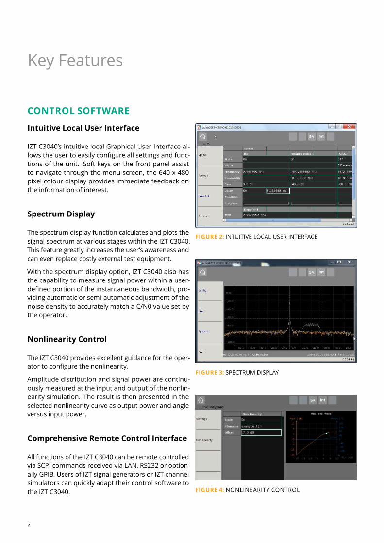
CONTROL SOFTWAREIntuitive Local User InterfaceIZT C3040’s intuitive local Graphical User Interface al-
lows the user to easily configure all settings and func-
tions of the unit. Soft keys on the front panel assist
to navigate through the menu screen, the 640 x 480
pixel colour display provides immediate feedback on
the information of interest.
Spectrum DisplayThe spectrum display function calculates and plots the
signal spectrum at various stages within the IZT C3040.
This feature greatly increases the user’s awareness and
can even replace costly external test equipment.
With the spectrum display option, IZT C3040 also has
the capability to measure signal power within a user-
defined portion of the instantaneous bandwidth, pro-
viding automatic or semi-automatic adjustment of the
noise density to accurately match a C/N0 value set by
the operator.
Nonlinearity ControlThe IZT C3040 provides excellent guidance for the oper-
ator to configure the nonlinearity.
Amplitude distribution and signal power are continu-
ously measured at the input and output of the nonlin-
earity simulation. The result is then presented in the
selected nonlinearity curve as output power and angle
versus input power.
Comprehensive Remote Control InterfaceAll functions of the IZT C3040 can be remote controlled
via SCPI commands received via LAN, RS232 or option-
ally GPIB. Users of IZT signal generators or IZT channel
simulators can quickly adapt their control software to
the IZT C3040.
FIGURE 2: INTUITIVE LOCAL USER INTERFACE
FIGURE 3: SPECTRUM DISPLAY
FIGURE 4: NONLINEARITY CONTROL
5
IZT C3040 | Satellite Link Simulator
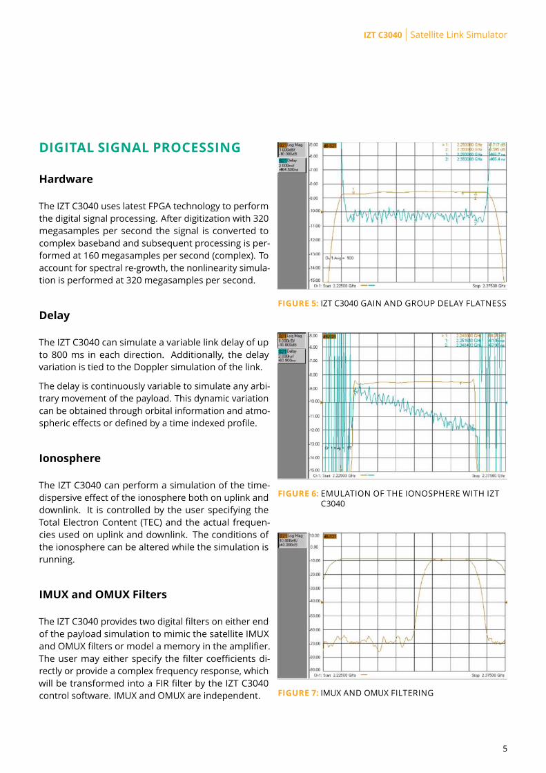
DIGITAL SIGNAL PROCESSINGHardwareThe IZT C3040 uses latest FPGA technology to perform
the digital signal processing. After digitization with 320
megasamples per second the signal is converted to
complex baseband and subsequent processing is per-
formed at 160 megasamples per second (complex). To
account for spectral re-growth, the nonlinearity simula-
tion is performed at 320 megasamples per second.
DelayThe IZT C3040 can simulate a variable link delay of up
to 800 ms in each direction. Additionally, the delay
variation is tied to the Doppler simulation of the link.
The delay is continuously variable to simulate any arbi-
trary movement of the payload. This dynamic variation
can be obtained through orbital information and atmo-
spheric effects or defined by a time indexed profile.
IonosphereThe IZT C3040 can perform a simulation of the time-
dispersive effect of the ionosphere both on uplink and
downlink. It is controlled by the user specifying the
Total Electron Content (TEC) and the actual frequen-
cies used on uplink and downlink. The conditions of
the ionosphere can be altered while the simulation is
running.
IMUX and OMUX FiltersThe IZT C3040 provides two digital filters on either end
of the payload simulation to mimic the satellite IMUX
and OMUX filters or model a memory in the amplifier.
The user may either specify the filter coefficients di-
rectly or provide a complex frequency response, which
will be transformed into a FIR filter by the IZT C3040
control software. IMUX and OMUX are independent.
FIGURE 5: IZT C3040 GAIN AND GROUP DELAY FLATNESS
FIGURE 6: EMULATION OF THE IONOSPHERE WITH IZT
C3040
FIGURE 7: IMUX AND OMUX FILTERING
6
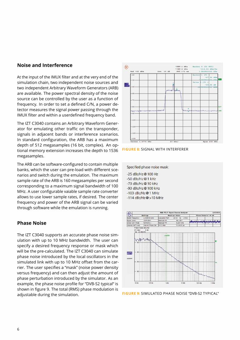
Noise and InterferenceAt the input of the IMUX filter and at the very end of the
simulation chain, two independent noise sources and
two independent Arbitrary Waveform Generators (ARB)
are available. The power spectral density of the noise
source can be controlled by the user as a function of
frequency. In order to set a defined C/N, a power de-
tector measures the signal power passing through the
IMUX filter and within a userdefined frequency band.
The IZT C3040 contains an Arbitrary Waveform Gener-
ator for emulating other traffic on the transponder,
signals in adjacent bands or interference scenarios.
In standard configuration, the ARB has a maximum
depth of 512 megasamples (16 bit, complex). An op-
tional memory extension increases the depth to 1536
megasamples.
The ARB can be software-configured to contain multiple
banks, which the user can pre-load with different sce-
narios and switch during the emulation. The maximum
sample rate of the ARB is 160 megasamples per second
corresponding to a maximum signal bandwidth of 100
MHz. A user configurable vaiable sample rate converter
allows to use lower sample rates, if desired. The center
frequency and power of the ARB signal can be varied
through software while the emulation is running.
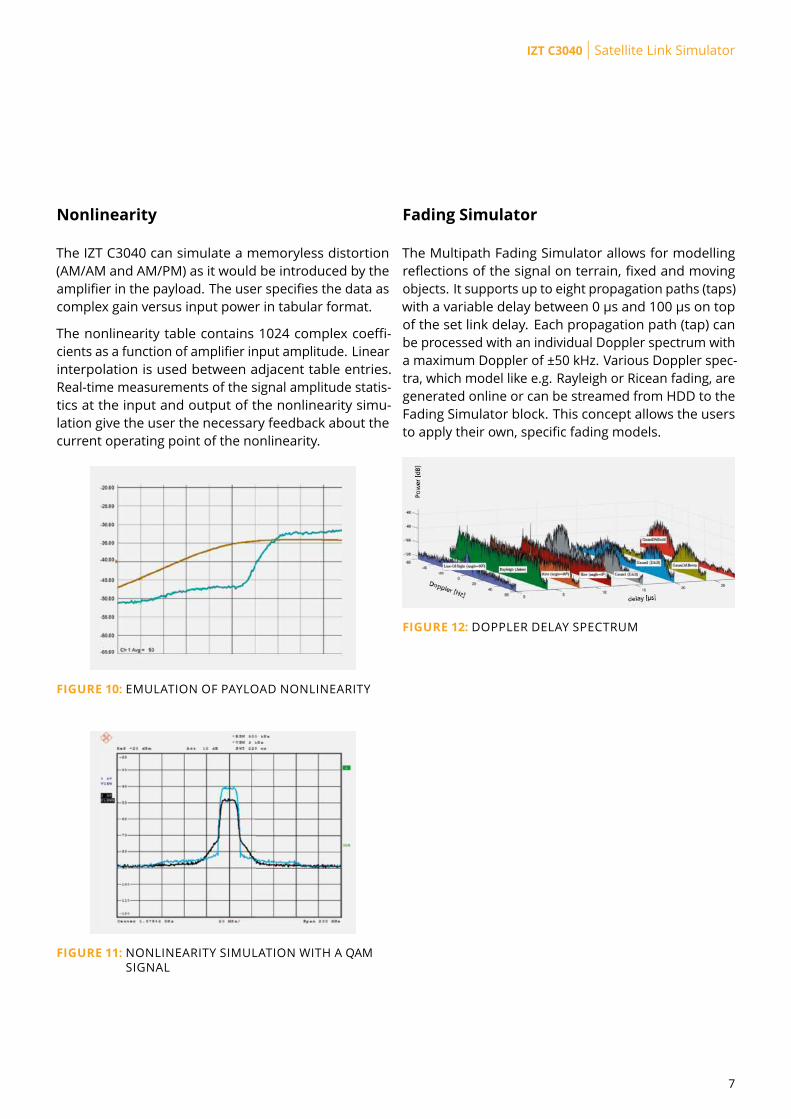
Phase NoiseThe IZT C3040 supports an accurate phase noise sim-
ulation with up to 10 MHz bandwidth. The user can
specify a desired frequency response or mask which
will be the pre-calculated. The IZT C3040 can simulate
phase noise introduced by the local oscillators in the
simulated link with up to 10 MHz offset from the car-
rier. The user specifies a “mask” (noise power density
versus frequency) and can then adjust the amount of
phase perturbation introduced by the simulator. As an
example, the phase noise profile for “DVB-S2 typical“ is
shown in figure 9. The total (RMS) phase modulation is
adjustable during the simulation.
FIGURE 8: SIGNAL WITH INTERFERER
FIGURE 9: SIMULATED PHASE NOISE “DVB-S2 TYPICAL”
7
IZT C3040 | Satellite Link Simulator
NonlinearityThe IZT C3040 can simulate a memoryless distortion
(AM/AM and AM/PM) as it would be introduced by the
amplifier in the payload. The user specifies the data as
complex gain versus input power in tabular format.
The nonlinearity table contains 1024 complex coeffi-
cients as a function of amplifier input amplitude. Linear
interpolation is used between adjacent table entries.
Real-time measurements of the signal amplitude statis-
tics at the input and output of the nonlinearity simu-
lation give the user the necessary feedback about the
current operating point of the nonlinearity.
FIGURE 10: EMULATION OF PAYLOAD NONLINEARITY
FIGURE 11: NONLINEARITY SIMULATION WITH A QAM
SIGNAL
Fading SimulatorThe Multipath Fading Simulator allows for modelling
reflections of the signal on terrain, fixed and moving
objects. It supports up to eight propagation paths (taps)
with a variable delay between 0 µs and 100 µs on top
of the set link delay. Each propagation path (tap) can
be processed with an individual Doppler spectrum with
a maximum Doppler of ±50 kHz. Various Doppler spec-
tra, which model like e.g. Rayleigh or Ricean fading, are
generated online or can be streamed from HDD to the
Fading Simulator block. This concept allows the users
to apply their own, specific fading models.
FIGURE 12: DOPPLER DELAY SPECTRUM
8
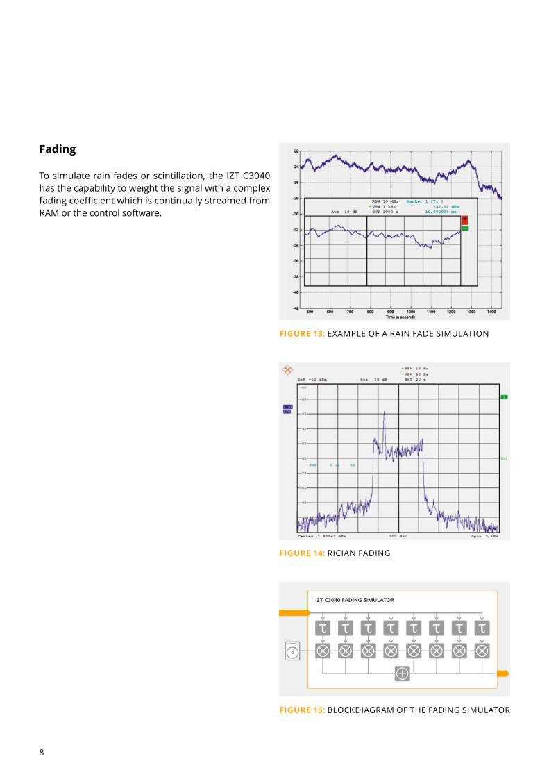
FadingTo simulate rain fades or scintillation, the IZT C3040
has the capability to weight the signal with a complex
fading coefficient which is continually streamed from
RAM or the control software.
FIGURE 13: EXAMPLE OF A RAIN FADE SIMULATION
FIGURE 14: RICIAN FADING
FIGURE 15: BLOCKDIAGRAM OF THE FADING SIMULATOR
9
IZT C3040 | Satellite Link Simulator
Real-Time InterfaceThe real-time interface allows users to reconfigure one
or multiple IZT C3040 precisely every 100 ms. Using a
timestamp mechanism the new values for delay, fre-
quency shift and gain are send by the user in advance
(at least 250 ms before the time is reached) and will be
executed by the FPGA exactly at the specified instance.
Key features of the real-time interface are:
Reconf guration of delay, frequency shift and gain
Reconf guration every 100 ms possible (or less if no
update needed)
Windows COM Driver allows use of RTI in C++, C#,
MATLAB and others
TM1 Fading ModelThis terrestrial fading model implements a two-ray mul-
tipath model (Rummler model) with 6.3 ns delay be-
tween the main (stronger) and secondary path rays.
The main path may either lead (minimum phase) or lag
(non minimum phase) the secondary path. Additionally
the user can configure the frequency offset and depth
of the so created notch. Time variant configuration of
the frequency offset and the depth of the notch allow
to test realistic scenarios.
Analog PerformanceThe IZT C3040 uses high performance broadband RF
converters which it shares with IZT’s receivers and
signal sources. This minimizes uncontrolled and un-
wanted degradation of signal quality in the system un-
der test.
The IZT C3040 uses sophisticated digital correction of
the analogue frequency response which results in a typ-
ical amplitude ripple of ±0.5 dB and ±1 ns group delay
ripple over its 100 MHz instantaneous bandwidth.
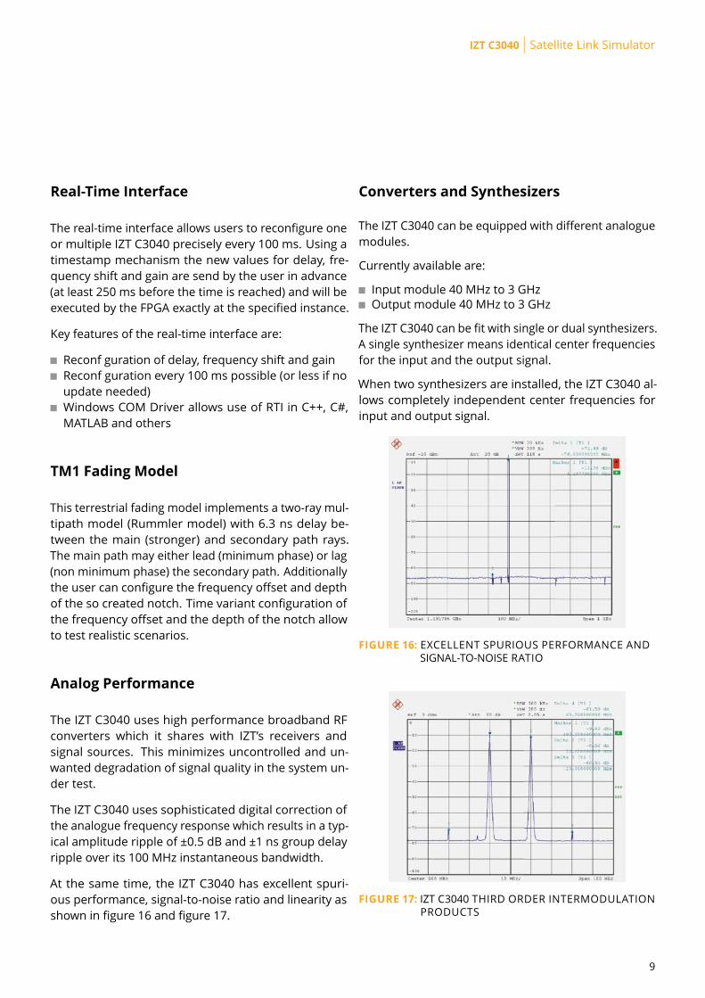
At the same time, the IZT C3040 has excellent spuri-
ous performance, signal-to-noise ratio and linearity as
shown in figure 16 and figure 17.
Converters and SynthesizersThe IZT C3040 can be equipped with different analogue
modules.
Currently available are:
Input module 40 MHz to 3 GHz
Output module 40 MHz to 3 GHz
The IZT C3040 can be fit with single or dual synthesizers.
A single synthesizer means identical center frequencies
for the input and the output signal.
When two synthesizers are installed, the IZT C3040 al-
lows completely independent center frequencies for
input and output signal.
FIGURE 16: EXCELLENT SPURIOUS PERFORMANCE ANDSIGNAL-TO-NOISE RATIO
FIGURE 17: IZT C3040 THIRD ORDER INTERMODULATIONPRODUCTS
10
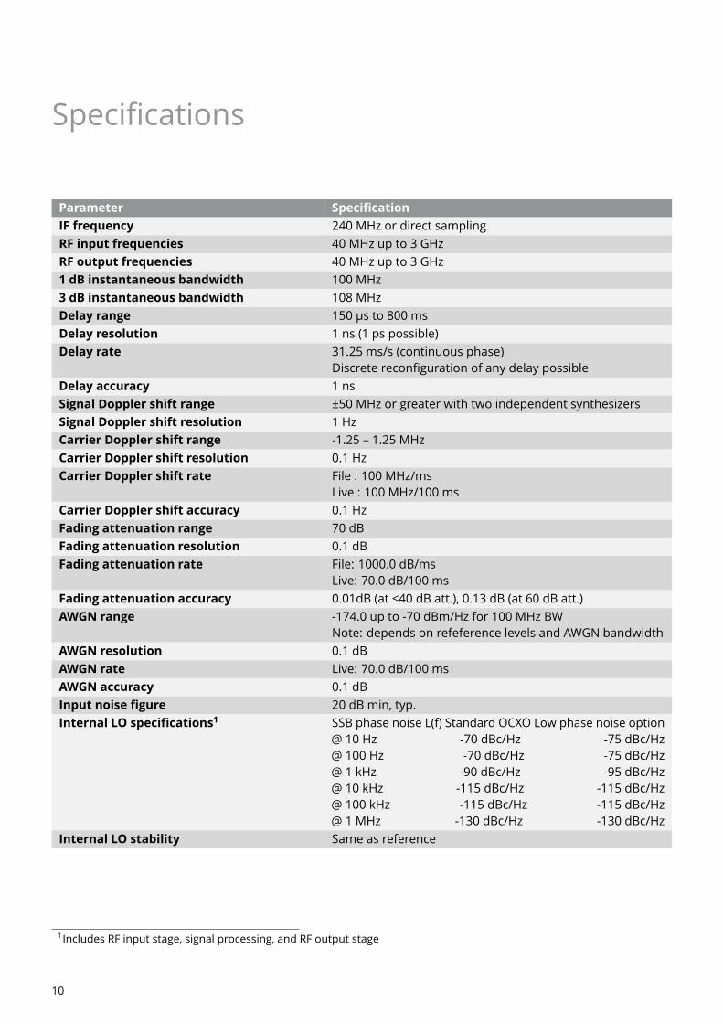
Specifications
Parameter SpecificationIF frequency 240 MHz or direct sampling
RF input frequencies 40 MHz up to 3 GHz
RF output frequencies 40 MHz up to 3 GHz
1 dB instantaneous bandwidth 100 MHz
3 dB instantaneous bandwidth 108 MHz
Delay range 150 µs to 800 ms
Delay resolution 1 ns (1 ps possible)
Delay rate 31.25 ms/s (continuous phase)
Discrete reconfiguration of any delay possible
Delay accuracy 1 ns
Signal Doppler shift range ±50 MHz or greater with two independent synthesizers
Signal Doppler shift resolution 1 Hz
Carrier Doppler shift range -1.25 – 1.25 MHz
Carrier Doppler shift resolution 0.1 Hz
Carrier Doppler shift rate File : 100 MHz/ms
Live : 100 MHz/100 ms
Carrier Doppler shift accuracy 0.1 Hz
Fading attenuation range 70 dB
Fading attenuation resolution 0.1 dB
Fading attenuation rate File: 1000.0 dB/ms
Live: 70.0 dB/100 ms
Fading attenuation accuracy 0.01dB (at <40 dB att.), 0.13 dB (at 60 dB att.)
AWGN range -174.0 up to -70 dBm/Hz for 100 MHz BW
Note: depends on refeference levels and AWGN bandwidth
AWGN resolution 0.1 dB
AWGN rate Live: 70.0 dB/100 ms
AWGN accuracy 0.1 dB
Input noise figure 20 dB min, typ.
Internal LO specifications1 SSB phase noise L(f) Standard OCXO Low phase noise option
@ 10 Hz -70 dBc/Hz -75 dBc/Hz
@ 100 Hz -70 dBc/Hz -75 dBc/Hz
@ 1 kHz -90 dBc/Hz -95 dBc/Hz
@ 10 kHz -115 dBc/Hz -115 dBc/Hz
@ 100 kHz -115 dBc/Hz -115 dBc/Hz
@ 1 MHz -130 dBc/Hz -130 dBc/Hz
Internal LO stability Same as reference
1Includes RF input stage, signal processing, and RF output stage
11
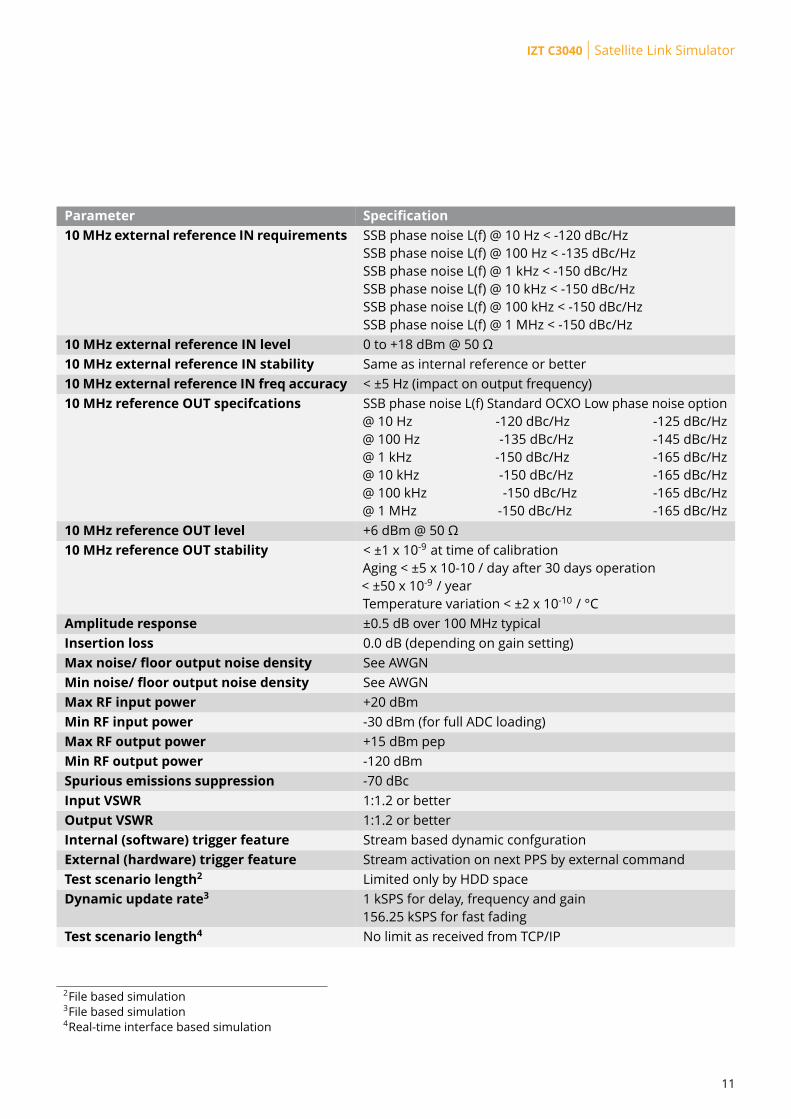
IZT C3040 | Satellite Link Simulator
Parameter Specification10MHz external reference IN requirements SSB phase noise L(f) @ 10 Hz < -120 dBc/Hz
SSB phase noise L(f) @ 100 Hz < -135 dBc/Hz
SSB phase noise L(f) @ 1 kHz < -150 dBc/Hz
SSB phase noise L(f) @ 10 kHz < -150 dBc/Hz
SSB phase noise L(f) @ 100 kHz < -150 dBc/Hz
SSB phase noise L(f) @ 1 MHz < -150 dBc/Hz
10 MHz external reference IN level 0 to +18 dBm @ 50 Ω
10 MHz external reference IN stability Same as internal reference or better
10 MHz external reference IN freq accuracy < ±5 Hz (impact on output frequency)
10 MHz reference OUT specifcations SSB phase noise L(f) Standard OCXO Low phase noise option
@ 10 Hz -120 dBc/Hz -125 dBc/Hz
@ 100 Hz -135 dBc/Hz -145 dBc/Hz
@ 1 kHz -150 dBc/Hz -165 dBc/Hz
@ 10 kHz -150 dBc/Hz -165 dBc/Hz
@ 100 kHz -150 dBc/Hz -165 dBc/Hz
@ 1 MHz -150 dBc/Hz -165 dBc/Hz
10 MHz reference OUT level +6 dBm @ 50 Ω
10 MHz reference OUT stability < ±1 x 10⁻⁹ at time of calibration
Aging < ±5 x 10⁻¹⁰ / day after 30 days operation
< ±50 x 10-9 / year
Temperature variation < ±2 x 10⁻¹⁰ / °C
Amplitude response ±0.5 dB over 100 MHz typical
Insertion loss 0.0 dB (depending on gain setting)
Max noise/ floor output noise density See AWGN
Min noise/ floor output noise density See AWGN
Max RF input power +20 dBm
Min RF input power -30 dBm (for full ADC loading)
Max RF output power +15 dBm pep
Min RF output power -120 dBm
Spurious emissions suppression -70 dBc
Input VSWR 1:1.2 or better
Output VSWR 1:1.2 or better
Internal (software) trigger feature Stream based dynamic confguration
External (hardware) trigger feature Stream activation on next PPS by external command
Test scenario length2 Limited only by HDD space
Dynamic update rate3 1 kSPS for delay, frequency and gain
156.25 kSPS for fast fading
Test scenario length4 No limit as received from TCP/IP
2File based simulation3File based simulation4Real-time interface based simulation
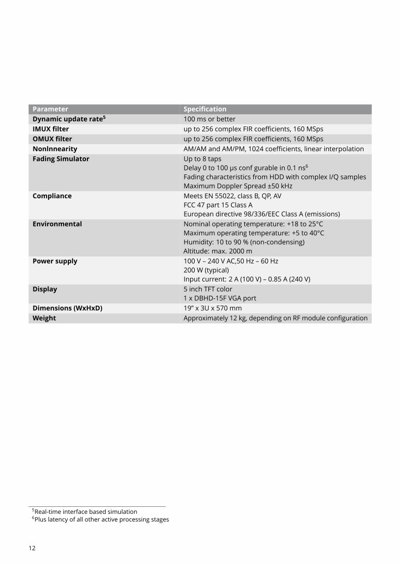
12
Parameter SpecificationDynamic update rate5 100 ms or better
IMUX filter up to 256 complex FIR coefficients, 160 MSps
OMUX filter up to 256 complex FIR coefficients, 160 MSps
Nonlnnearity AM/AM and AM/PM, 1024 coefficients, linear interpolation
Fading Simulator Up to 8 taps
Delay 0 to 100 µs conf gurable in 0.1 ns6
Fading characteristics from HDD with complex I/Q samples
Maximum Doppler Spread ±50 kHz
Compliance Meets EN 55022, class B, QP, AV
FCC 47 part 15 Class A
European directive 98/336/EEC Class A (emissions)
Environmental Nominal operating temperature: +18 to 25°C
Maximum operating temperature: +5 to 40°C
Humidity: 10 to 90 % (non-condensing)
Altitude: max. 2000 m
Power supply 100 V – 240 V AC,50 Hz – 60 Hz
200 W (typical)
Input current: 2 A (100 V) – 0.85 A (240 V)
Display 5 inch TFT color
1 x DBHD-15F VGA port
Dimensions (WxHxD) 19” x 3U x 570 mm
Weight Approximately 12 kg, depending on RF module configuration
5Real-time interface based simulation6Plus latency of all other active processing stages
13
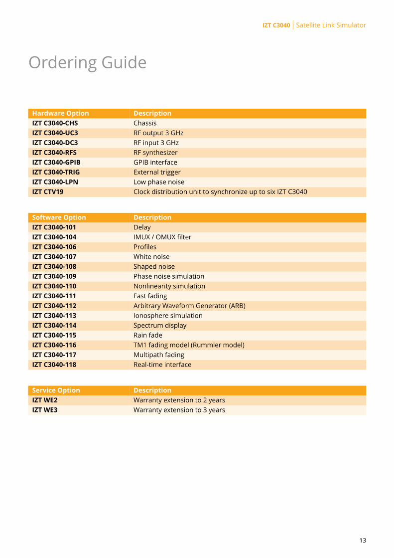
IZT C3040 | Satellite Link Simulator
Ordering Guide
Hardware Option DescriptionIZT C3040-CHS Chassis
IZT C3040-UC3 RF output 3 GHz
IZT C3040-DC3 RF input 3 GHz
IZT C3040-RFS RF synthesizer
IZT C3040-GPIB GPIB interface
IZT C3040-TRIG External trigger
IZT C3040-LPN Low phase noise
IZT CTV19 Clock distribution unit to synchronize up to six IZT C3040
Software Option DescriptionIZT C3040-101 Delay
IZT C3040-104 IMUX / OMUX filter
IZT C3040-106 Profiles
IZT C3040-107 White noise
IZT C3040-108 Shaped noise
IZT C3040-109 Phase noise simulation
IZT C3040-110 Nonlinearity simulation
IZT C3040-111 Fast fading
IZT C3040-112 Arbitrary Waveform Generator (ARB)
IZT C3040-113 Ionosphere simulation
IZT C3040-114 Spectrum display
IZT C3040-115 Rain fade
IZT C3040-116 TM1 fading model (Rummler model)
IZT C3040-117 Multipath fading
IZT C3040-118 Real-time interface
Service Option DescriptionIZT WE2 Warranty extension to 2 years
IZT WE3 Warranty extension to 3 years
Produc
tInformationIZT C3040
Satellite Link Simulator
About IZT The Innovationszentrum fuer Telekommunikationstechnik GmbH IZT specializes in the most advanced digital signal pro-
cessing and field programmable gate array (FPGA) designs in combination with high frequency and microwave technology.
The product portfolio includes equipment for signal generation, receivers for signal monitoring and recording, transmitters for digi-
tal broadcast, digital radio systems, and channel simulators. IZT offers powerful platforms and customized solutions for high signal
bandwidth and real-time signal processing applications. The product and project business is managed from the principal office lo-
cated in Erlangen/Germany. IZT distributes its products worldwide together with its international strategic partners. The IZT quality
management system is ISO 9001:2015 certified.
All data provided in this document is non-binding.This data serves informational purposes only and is especially not guaranteed in anyway. Depending upon the subsequent specific individual projects, the relevant data may be subject to changes and will be assessed anddetermined individually for each project. This will depend on the particular characteristics of each individual project, especially specific siteand operational conditions.INNOVATIONSZENTRUM FÜR TELEKOMMUNIKATIONSTECHNIK GMBH IZT AM WEICHSELGARTEN 5 · 91058 ERLANGEN, GERMANYGENERAL MANAGER: RAINER PERTHOLD · TEL: +49 (0)9131 9162-0 · FAX: -190 · [email protected] ·WWW.IZT-LABS.DE
REV.4.00|01.02.2020