Embed Size (px)
Citation preview
IWAN Security for Remote Site Direct Internet Access and Guest WirelessTechnology Design Guide (ISR4K)
March 2015
Table of Contents
Table of ContentsPreface ........................................................................................................................................1
CVD Navigator .............................................................................................................................2Use Cases .................................................................................................................................. 2Scope ......................................................................................................................................... 2Proficiency .................................................................................................................................. 2
Introduction .................................................................................................................................3Related Reading .......................................................................................................................... 3Technology Use Cases ............................................................................................................... 3
Use Case: DIA for Remote-Site Internal Employees ............................................................... 4Use Case: DIA from Remote-Site Guest Wireless Users ........................................................ 5
Overview of Cisco IWAN and Secure DIA .................................................................................. 5IWAN Remote-Site Design ..................................................................................................... 6IWAN Remote-Site Design with DIA ..................................................................................... 10IWAN High Availability ............................................................................................................12Securing DIA ........................................................................................................................13
Direct Internet Access Design ....................................................................................................16Design Detail ............................................................................................................................. 16
IWAN DIA Routing with Front Door VRF ................................................................................17IWAN Single-Router Hybrid Remote-Site Routing ..................................................................19IWAN Dual-Router Hybrid Remote Site Routing .................................................................... 22IWAN Single-Router, Dual-Internet Remote-Site Routing ...................................................... 26IWAN Dual-Router, Dual-Internet Remote Site Routing ......................................................... 29
Deploying Direct Internet Access ...............................................................................................33Using This Section .................................................................................................................... 33IWAN Single-Router Hybrid Remote Site with DIA .................................................................... 34
Configuring DIA Routing ....................................................................................................... 34Configuring Single-Router Remote Site with Layer 3 Distribution ......................................... 38Configuring Network Address Translation for DIA ................................................................. 40Configuring Zone-Based Firewall for DIA .............................................................................. 42Configuring Additional Router Security ................................................................................. 50Configuring ISP Black-Hole Routing Detection ...................................................................... 54
IWAN Dual-Router Hybrid Remote Site with DIA ....................................................................... 59
Table of Contents
Configuring DIA Routing ....................................................................................................... 60Configuring Network Address Translation for DIA ................................................................. 66Configuring Zone-Based Firewall for DIA .............................................................................. 68Configuring Additional Router Security ................................................................................. 76Configuring ISP Black-Hole Routing Detection ...................................................................... 80
IWAN Single-Router Dual-Internet Remote Site with DIA .......................................................... 85Configuring DIA Routing ....................................................................................................... 86Configuring Single-Router Remote Site with Layer 3 Distribution ......................................... 89Configuring Network Address Translation for DIA ................................................................. 91Configuring Zone-Based Firewall for DIA .............................................................................. 94Configuring Additional Router Security ............................................................................... 105Configuring ISP Black-Hole Routing Detection .................................................................... 109
IWAN Dual-Router Dual-Internet Remote Site with DIA ............................................................114Configuring DIA Routing ......................................................................................................115Configuring Network Address Translation for DIA ................................................................121Configuring Zone-Based Firewall for DIA .............................................................................123Configuring Additional Router Security ................................................................................132Configuring ISP Black-Hole Routing Detection .................................................................... 136
Deploying Remote Site Guest Wireless Access ........................................................................ 141IWAN Guest Access Routing ................................................................................................... 143
Configuring Guest Basic Network Connectivity .................................................................. 143Configuring Guest Authentication and DIA Routing ..............................................................146Configuring Guest NAT for DIA ........................................................................................... 148
Configuring Zone-Based Firewall for Guest DIA Options ..........................................................151Configuring Guest DIA, Option 1: Employee Central Internet ...............................................152Configuring Guest DIA, Option 2: Employee DIA ................................................................ 163
IWAN Guest Access Wireless ................................................................................................. 169Deploying Guest Wireless by Using AireOS and FlexConnect ..................................................171
Configuring Guest VLAN at Remote Site .............................................................................171Configuring Local Web Authentication on WLC Running AireOS with FlexConnect .............172Configuring Central Web Authentication on WLC running AireOS with FlexConnect ...........179
Guest Wireless Using Local Controller with AireOS ................................................................ 188Configuring Local Web Authentication on Remote WLC Running AireOS ........................... 188Configuring Central Web Authentication on Local WLC Running AireOS ............................ 194
Guest Wireless Using Unified Access Switches ...................................................................... 201Configuring Local Web Authentication on a Unified Access Switch .................................... 201Configuring Central Web Authentication on Unified Access Switch .................................... 204
Table of Contents
Configuring Identity Services Engine....................................................................................... 207Implementing ISE for CWA ................................................................................................. 207Logging In As a Guest User ................................................................................................ 228
Appendix A: Product List .........................................................................................................231
Appendix B: Router Configurations ..........................................................................................238Single Router Hybrid with DIA and Guest Access ................................................................... 238
RS31-4451X ....................................................................................................................... 238Dual Router hybrid with DIA .................................................................................................... 254
RS32-4451X-2 Secondary Router ...................................................................................... 254Single-Router Dual-Internet with Guest Access ...................................................................... 266
RS33-4451X ....................................................................................................................... 266Dual-Router Dual-Internet ....................................................................................................... 283
RS34-4451X-1 Primary Router ........................................................................................... 283
Appendix C: Glossary ..............................................................................................................296
Preface March 20151
PrefaceCisco Validated Designs (CVDs) present systems that are based on common use cases or engineering priorities. CVDs incorporate a broad set of technologies, features, and applications that address customer needs. Cisco engineers have comprehensively tested and documented each design in order to ensure faster, more reliable, and fully predictable deployment.
CVDs include two guide types that provide tested design details:
• Technology design guides provide deployment details, information about validated products and software, and best practices for specific types of technology.
• Solution design guides integrate existing CVDs but also include product features and functionality across Cisco products and sometimes include information about third-party integration.
Both CVD types provide a tested starting point for Cisco partners or customers to begin designing and deploying systems.
CVD Foundation SeriesThis CVD Foundation guide is a part of the January 2015 Series. As Cisco develops a CVD Foundation series, the guides themselves are tested together, in the same network lab. This approach assures that the guides in a series are fully compatible with one another. Each series describes a lab-validated, complete system.
The CVD Foundation series incorporates wired and wireless LAN, WAN, data center, security, and network management technologies. Using the CVD Foundation simplifies system integration, allowing you to select solutions that solve an organization’s problems—without worrying about the technical complexity.
To ensure the compatibility of designs in the CVD Foundation, you should use guides that belong to the same release. For the most recent CVD Foundation guides, please visit the CVD Foundation web site.
Comments and QuestionsIf you would like to comment on a guide or ask questions, please use the feedback form.
CVD Navigator March 20152
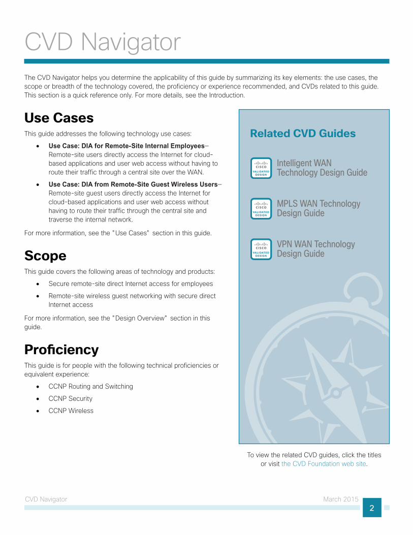
CVD NavigatorThe CVD Navigator helps you determine the applicability of this guide by summarizing its key elements: the use cases, the scope or breadth of the technology covered, the proficiency or experience recommended, and CVDs related to this guide. This section is a quick reference only. For more details, see the Introduction.
Use CasesThis guide addresses the following technology use cases:
• Use Case: DIA for Remote-Site Internal Employees—Remote-site users directly access the Internet for cloud-based applications and user web access without having to route their traffic through a central site over the WAN.
• Use Case: DIA from Remote-Site Guest Wireless Users—Remote-site guest users directly access the Internet for cloud-based applications and user web access without having to route their traffic through the central site and traverse the internal network.
For more information, see the "Use Cases" section in this guide.
ScopeThis guide covers the following areas of technology and products:
• Secure remote-site direct Internet access for employees
• Remote-site wireless guest networking with secure direct Internet access
For more information, see the "Design Overview" section in this guide.
ProficiencyThis guide is for people with the following technical proficiencies or equivalent experience:
• CCNP Routing and Switching
• CCNP Security
• CCNP Wireless
To view the related CVD guides, click the titles or visit the CVD Foundation web site.
Related CVD Guides
Intelligent WANTechnology Design GuideVALIDATED
DESIGN
VALIDATEDDESIGN
MPLS WAN TechnologyDesign Guide
VALIDATEDDESIGN
VPN WAN TechnologyDesign Guide
Introduction March 20153
IntroductionSecurity is an essential component of Cisco Intelligent WAN (IWAN). Cisco IWAN delivers an uncompromised user experience over any connection, allowing an organization to right-size their network with operational simplicity and lower costs while reducing security risks.
This guide describes how to reduce WAN bandwidth and improve user experience by enabling secure direct access to the Internet at each remote site, without routing employee and guest traffic to central network locations.
Related ReadingThe Intelligent WAN Technology Design Guide provides configuration and deployment guidance for IWAN routing with enhanced interior gateway routing protocol (EIGRP) named mode, dynamic multipoint virtual private network version 3 (DMVPNv3), public key infrastructure (PKI), and performance routing version 3 (PfRv3) for Cisco IWAN.
Technology Use CasesFor remote-site users to effectively support the business, organizations require that the wide-area network (WAN) provide sufficient performance, reliability, and security.
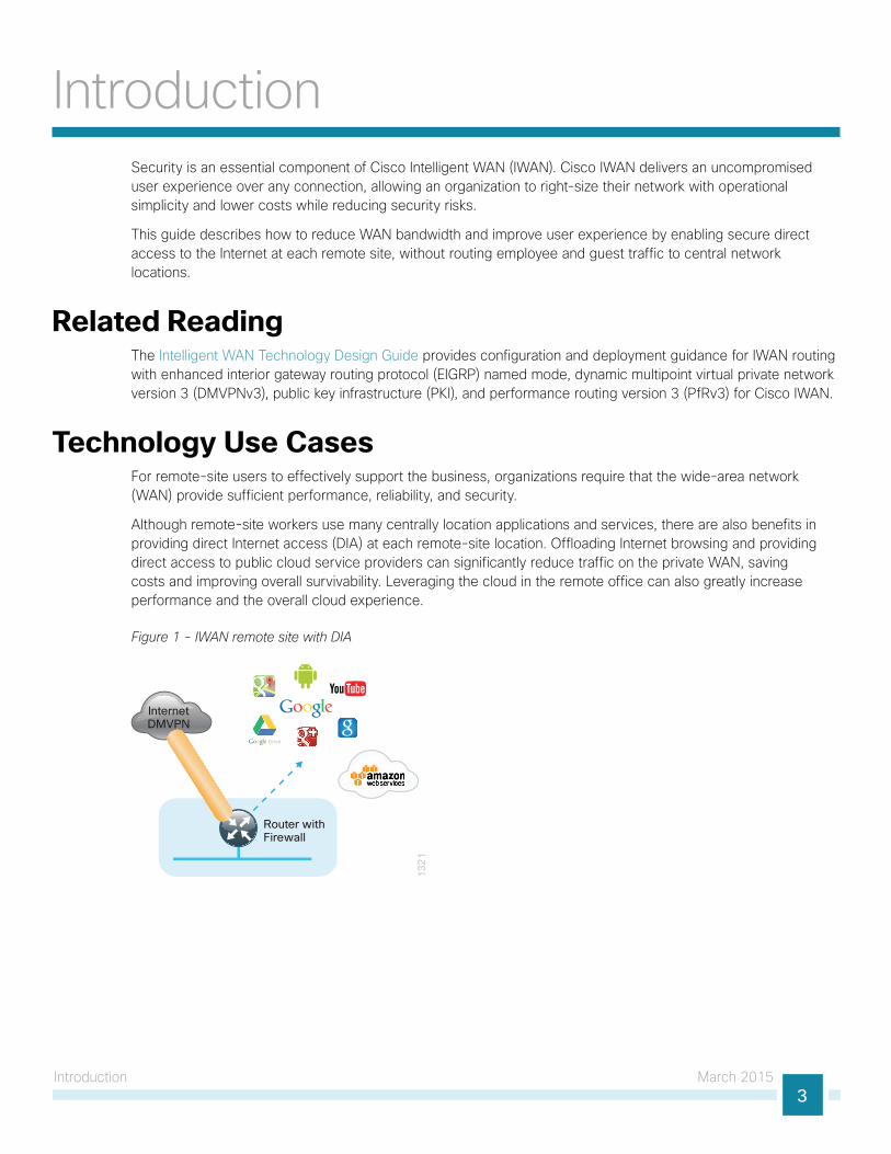
Although remote-site workers use many centrally location applications and services, there are also benefits in providing direct Internet access (DIA) at each remote-site location. Offloading Internet browsing and providing direct access to public cloud service providers can significantly reduce traffic on the private WAN, saving costs and improving overall survivability. Leveraging the cloud in the remote office can also greatly increase performance and the overall cloud experience.
Figure 1 - IWAN remote site with DIA
13
21
Router withFirewall
InternetDMVPN
Introduction March 20154
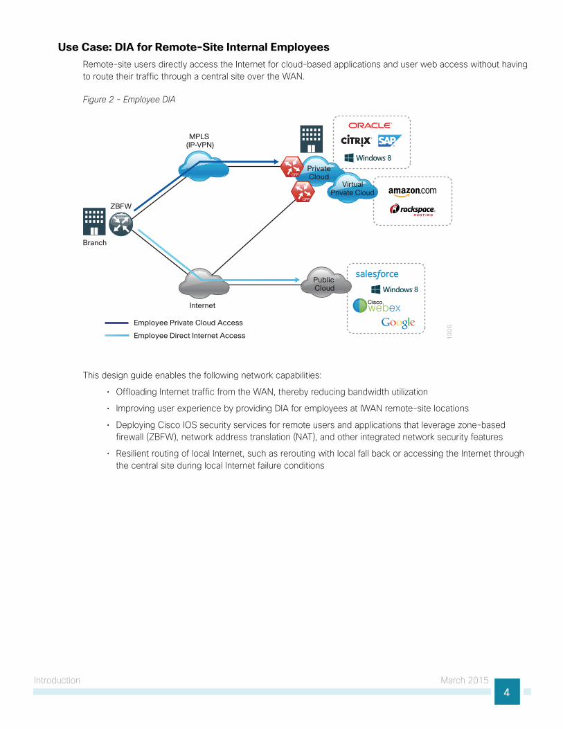
Use Case: DIA for Remote-Site Internal Employees Remote-site users directly access the Internet for cloud-based applications and user web access without having to route their traffic through a central site over the WAN.
Figure 2 - Employee DIA
13
06
Internet
PrivateCloud
VirtualPrivate Cloud
Public Cloud
Ciscowebex
MPLS (IP-VPN)
Employee Private Cloud Access
Employee Direct Internet Access
Branch
ZBFW
This design guide enables the following network capabilities:
• Offloading Internet traffic from the WAN, thereby reducing bandwidth utilization
• Improving user experience by providing DIA for employees at IWAN remote-site locations
• Deploying Cisco IOS security services for remote users and applications that leverage zone-based firewall (ZBFW), network address translation (NAT), and other integrated network security features
• Resilient routing of local Internet, such as rerouting with local fall back or accessing the Internet through the central site during local Internet failure conditions
Introduction March 20155
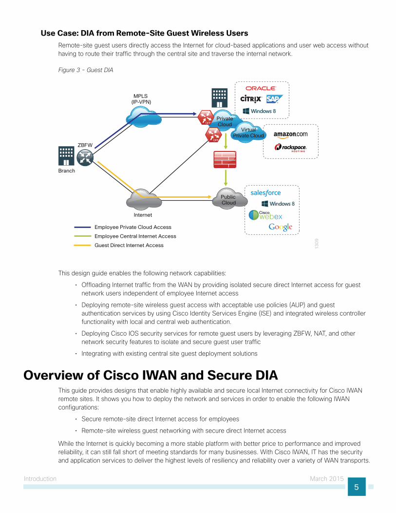
Use Case: DIA from Remote-Site Guest Wireless UsersRemote-site guest users directly access the Internet for cloud-based applications and user web access without having to route their traffic through the central site and traverse the internal network.
Figure 3 - Guest DIA
13
09
Internet
PrivateCloud
VirtualPrivate Cloud
Public Cloud
Ciscowebex
MPLS (IP-VPN)
Employee Private Cloud Access
Employee Central Internet Access
Guest Direct Internet Access
Branch
ZBFW
This design guide enables the following network capabilities:
• Offloading Internet traffic from the WAN by providing isolated secure direct Internet access for guest network users independent of employee Internet access
• Deploying remote-site wireless guest access with acceptable use policies (AUP) and guest authentication services by using Cisco Identity Services Engine (ISE) and integrated wireless controller functionality with local and central web authentication.
• Deploying Cisco IOS security services for remote guest users by leveraging ZBFW, NAT, and other network security features to isolate and secure guest user traffic
• Integrating with existing central site guest deployment solutions
Overview of Cisco IWAN and Secure DIA This guide provides designs that enable highly available and secure local Internet connectivity for Cisco IWAN remote sites. It shows you how to deploy the network and services in order to enable the following IWAN configurations:
• Secure remote-site direct Internet access for employees
• Remote-site wireless guest networking with secure direct Internet access
While the Internet is quickly becoming a more stable platform with better price to performance and improved reliability, it can still fall short of meeting standards for many businesses. With Cisco IWAN, IT has the security and application services to deliver the highest levels of resiliency and reliability over a variety of WAN transports.
Introduction March 20156
IWAN Remote-Site DesignThe modular nature of IWAN allows you to replicate common design elements throughout the network. All of the IWAN remote-site elements are standard building blocks in the overall design, providing a flexible, consistent, and scalable WAN deployment methodology.
Ethernet WANEthernet has traditionally been a local-area network (LAN) technology primarily due to the distance limitations of the available media and the requirement for dedicated copper or fiber links. Ethernet is becoming a dominant carrier handoff in many markets and it is relevant to include Ethernet as the primary media in the tested architectures. Much of the discussion in this guide can also be applied to non-Ethernet media (such as T1/E1, DS-3, OC-3, and so on), but those media are not explicitly discussed.
Private MPLS as IWAN TransportCisco IOS software multiprotocol label switching (MPLS) enables enterprises and service providers to build next-generation, intelligent networks that deliver a wide variety of advanced, value-added services over a single infrastructure. You can integrate this economical solution seamlessly over any existing infrastructure, such as IP, frame relay, asynchronous transfer mode (ATM), or Ethernet.
MPLS Layer 3 VPNs use a peer-to-peer VPN model that leverages the border gateway protocol (BGP) in order to distribute VPN-related information. This peer-to-peer model allows enterprise subscribers to outsource routing information to service providers, which can result in significant cost savings and a reduction in operational complexity for enterprises.
For more information about the implementation and design of MPLS VPN transport technologies as a building block of IWAN, see the MPLS WAN Technology Design Guide.
Reader Tip
Layer 2 WAN transports are now widely available from service providers and are able to extend various Layer 2 traffic types (for instance, frame relay, point to point, ATM, or Ethernet) over a WAN. The most common implementations of Layer 2 WAN are used to provide Ethernet over the WAN by using either a point-to-point or point-to-multipoint service.
Service providers implement these Ethernet services by using a variety of methods. MPLS networks support both Ethernet over MPLS (EoMPLS) and Virtual Private LAN Service (VPLS). You can use other network technologies, such as Ethernet switches in various topologies, to provide Ethernet Layer 2 WAN services.
For more information about the implementation and design of L2 transport technologies as a building block of IWAN, see the Layer 2 WAN Technology Design Guide.
Reader Tip
Introduction March 20157
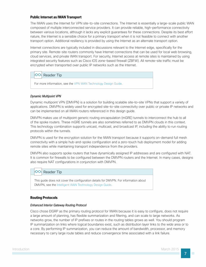
Public Internet as IWAN TransportThe IWAN uses the Internet for VPN site-to-site connections. The Internet is essentially a large-scale public WAN composed of multiple interconnected service providers. It can provide reliable, high-performance connectivity between various locations, although it lacks any explicit guarantees for these connections. Despite its best effort nature, the Internet is a sensible choice for a primary transport when it is not feasible to connect with another transport option. Additional resiliency is provided by using the Internet as an alternate transport option.
Internet connections are typically included in discussions relevant to the Internet edge, specifically for the primary site. Remote-site routers commonly have Internet connections that can be used for local web browsing, cloud services, and private WAN transport. For security, Internet access at remote sites is maintained by using integrated security features such as Cisco IOS zone-based firewall (ZBFW). All remote-site traffic must be encrypted when transported over public IP networks such as the Internet.
For more information, see the VPN WAN Technology Design Guide.
Reader Tip
Dynamic Multipoint VPN
Dynamic multipoint VPN (DMVPN) is a solution for building scalable site-to-site VPNs that support a variety of applications. DMVPN is widely used for encrypted site-to-site connectivity over public or private IP networks and can be implemented on all IWAN routers referenced in this design guide.
DMVPN makes use of multipoint generic routing encapsulation (mGRE) tunnels to interconnect the hub to all of the spoke routers. These mGRE tunnels are also sometimes referred to as DMVPN clouds in this context. This technology combination supports unicast, multicast, and broadcast IP, including the ability to run routing protocols within the tunnels.
DMVPN is used for the encryption solution for the IWAN transport because it supports on-demand full mesh connectivity with a simple hub-and-spoke configuration and a zero-touch hub deployment model for adding remote sites while maintaining transport independence from the providers.
DMVPN also supports spoke routers that have dynamically assigned IP addresses and are configured with NAT. It is common for firewalls to be configured between the DMVPN routers and the Internet. In many cases, designs also require NAT configurations in conjunction with DMVPN.
This guide does not cover the configuration details for DMVPN. For information about DMVPN, see the Intelligent WAN Technology Design Guide.
Reader Tip
Routing Protocols
Enhanced Interior Gateway Routing Protocol
Cisco chose EIGRP as the primary routing protocol for IWAN because it is easy to configure, does not require a large amount of planning, has flexible summarization and filtering, and can scale to large networks. As networks grow, the number of IP prefixes or routes in the routing tables grows as well. You should program IP summarization on links where logical boundaries exist, such as distribution layer links to the wide area or to a core. By performing IP summarization, you can reduce the amount of bandwidth, processor, and memory necessary to carry large route tables and reduce convergence time associated with a link failure.
Introduction March 20158
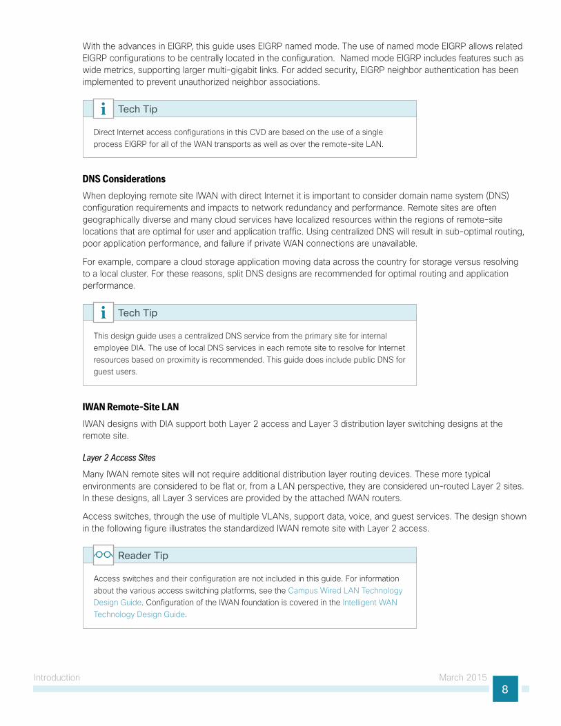
With the advances in EIGRP, this guide uses EIGRP named mode. The use of named mode EIGRP allows related EIGRP configurations to be centrally located in the configuration. Named mode EIGRP includes features such as wide metrics, supporting larger multi-gigabit links. For added security, EIGRP neighbor authentication has been implemented to prevent unauthorized neighbor associations.
Direct Internet access configurations in this CVD are based on the use of a single process EIGRP for all of the WAN transports as well as over the remote-site LAN.
Tech Tip
DNS ConsiderationsWhen deploying remote site IWAN with direct Internet it is important to consider domain name system (DNS) configuration requirements and impacts to network redundancy and performance. Remote sites are often geographically diverse and many cloud services have localized resources within the regions of remote-site locations that are optimal for user and application traffic. Using centralized DNS will result in sub-optimal routing, poor application performance, and failure if private WAN connections are unavailable.
For example, compare a cloud storage application moving data across the country for storage versus resolving to a local cluster. For these reasons, split DNS designs are recommended for optimal routing and application performance.
This design guide uses a centralized DNS service from the primary site for internal employee DIA. The use of local DNS services in each remote site to resolve for Internet resources based on proximity is recommended. This guide does include public DNS for guest users.
Tech Tip
IWAN Remote-Site LANIWAN designs with DIA support both Layer 2 access and Layer 3 distribution layer switching designs at the remote site.
Layer 2 Access Sites
Many IWAN remote sites will not require additional distribution layer routing devices. These more typical environments are considered to be flat or, from a LAN perspective, they are considered un-routed Layer 2 sites. In these designs, all Layer 3 services are provided by the attached IWAN routers.
Access switches, through the use of multiple VLANs, support data, voice, and guest services. The design shown in the following figure illustrates the standardized IWAN remote site with Layer 2 access.
Access switches and their configuration are not included in this guide. For information about the various access switching platforms, see the Campus Wired LAN Technology Design Guide. Configuration of the IWAN foundation is covered in the Intelligent WAN Technology Design Guide.
Reader Tip
Introduction March 20159
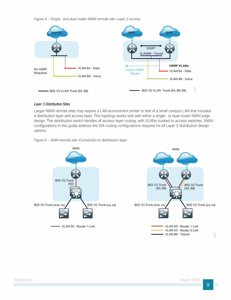
Figure 4 - Single- and dual-router IWAN remote site—Layer 2 access
13
20
Internet
No HSRPRequired
VLAN 64 - Data
802.1Q VLAN Trunk (64, 69)
VLAN 69 - Voice
WAN WAN
Active HSRP Router
VLAN 64 - Data
VLAN99 - Transit
802.1Q VLAN Trunk (64, 69, 99)
VLAN 69 - Voice
HSRP VLANs
EIGRP
Layer 3 Distribution Sites
Larger IWAN remote sites may require a LAN environment similar to that of a small campus LAN that includes a distribution layer and access layer. This topology works well with either a single- or dual-router IWAN edge design. The distribution switch handles all access-layer routing, with VLANs trunked to access switches. IWAN configurations in this guide address the DIA routing configurations required for all Layer 3 distribution design options.
Figure 5 - WAN remote site—Connection to distribution layer
20
07
WAN WAN
802.1Q Trunk(50)
802.1Q Trunk (ww, xx) 802.1Q Trunk (yy, zz) 802.1Q Trunk (ww, xx)
802.1Q Trunk(50, 99)
802.1Q Trunk(54, 99)
VLAN 50 - Router 1 LinkVLAN 54 - Router 2 LinkVLAN 99 - Transit
VLAN 50 - Router 1 Link
802.1Q Trunk (yy, zz)
Introduction March 201510
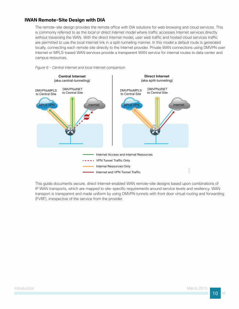
IWAN Remote-Site Design with DIAThe remote-site design provides the remote office with DIA solutions for web browsing and cloud services. This is commonly referred to as the local or direct Internet model where traffic accesses Internet services directly without traversing the WAN. With the direct Internet model, user web traffic and hosted cloud services traffic are permitted to use the local Internet link in a split-tunneling manner. In this model a default route is generated locally, connecting each remote site directly to the Internet provider. Private WAN connections using DMVPN over Internet or MPLS-based WAN services provide a transparent WAN service for internal routes to data center and campus resources.
Figure 6 - Central Internet and local Internet comparison
1249
InternetMPLS VPN
Central Internet(aka central-tunneling)
DMVPNoMPLSto Central Site
DMVPNoINET to Central Site
InternetMPLS VPN
Direct Internet(aka split-tunneling)
DMVPNoMPLSto Central Site
DMVPNoINET to Central Site
Internet Access and Internal Resources
VPN Tunnel Traffic Only
Internal Resources Only
Internet and VPN Tunnel Traffic
This guide documents secure, direct Internet-enabled WAN remote-site designs based upon combinations of IP WAN transports, which are mapped to site-specific requirements around service levels and resiliency. WAN transport is transparent and made uniform by using DMVPN tunnels with front door virtual routing and forwarding (FVRF), irrespective of the service from the provider.
Introduction March 201511
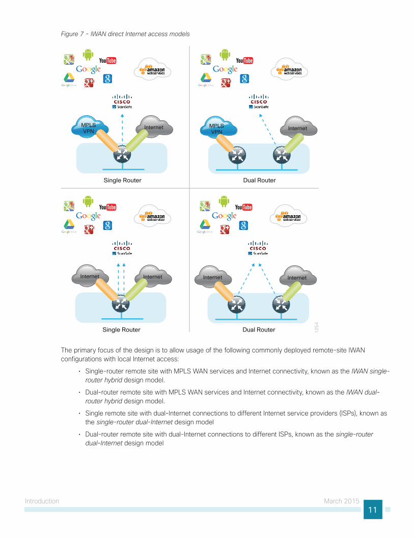
Figure 7 - IWAN direct Internet access models
InternetInternet
Single Router
MPLSVPN
Internet Internet
Dual Router
12
54
Single Router
Internet Internet
Dual Router
MPLSVPN
The primary focus of the design is to allow usage of the following commonly deployed remote-site IWAN configurations with local Internet access:
• Single-router remote site with MPLS WAN services and Internet connectivity, known as the IWAN single-router hybrid design model.
• Dual-router remote site with MPLS WAN services and Internet connectivity, known as the IWAN dual-router hybrid design model.
• Single remote site with dual-Internet connections to different Internet service providers (ISPs), known as the single-router dual-Internet design model
• Dual-router remote site with dual-Internet connections to different ISPs, known as the single-router dual-Internet design model
Introduction March 201512
The choice to use locally routed or direct Internet is locally significant to the remote site. No changes are required to the primary site.
The remote-site designs documented in this guide can be deployed in parallel with other remote-site designs that use centralized Internet access.
This guide does not address the primary aggregation site design and configuration details. This solution is tested and evaluated to work with the design models and WAN-aggregation site configurations as outlined in Intelligent WAN Technology Design Guide.
Reader Tip
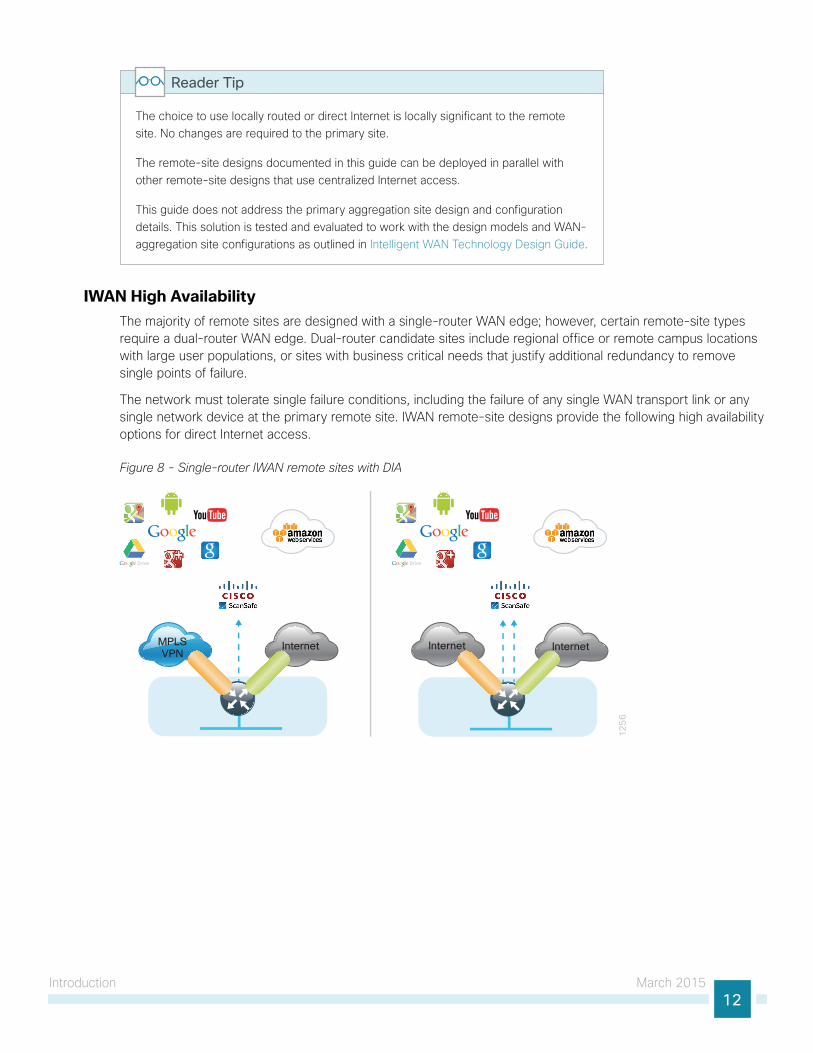
IWAN High AvailabilityThe majority of remote sites are designed with a single-router WAN edge; however, certain remote-site types require a dual-router WAN edge. Dual-router candidate sites include regional office or remote campus locations with large user populations, or sites with business critical needs that justify additional redundancy to remove single points of failure.
The network must tolerate single failure conditions, including the failure of any single WAN transport link or any single network device at the primary remote site. IWAN remote-site designs provide the following high availability options for direct Internet access.
Figure 8 - Single-router IWAN remote sites with DIA
InternetMPLSVPN
Internet
12
56
Internet
Introduction March 201513
Remote sites classified as single router may provide Internet failover in the event of local Internet link failure. Hybrid IWAN configurations may fail over to the central Internet model. Single-router dual-Internet IWAN configurations provide redundancy for local Internet connectivity by failing over to the secondary local Internet connection.
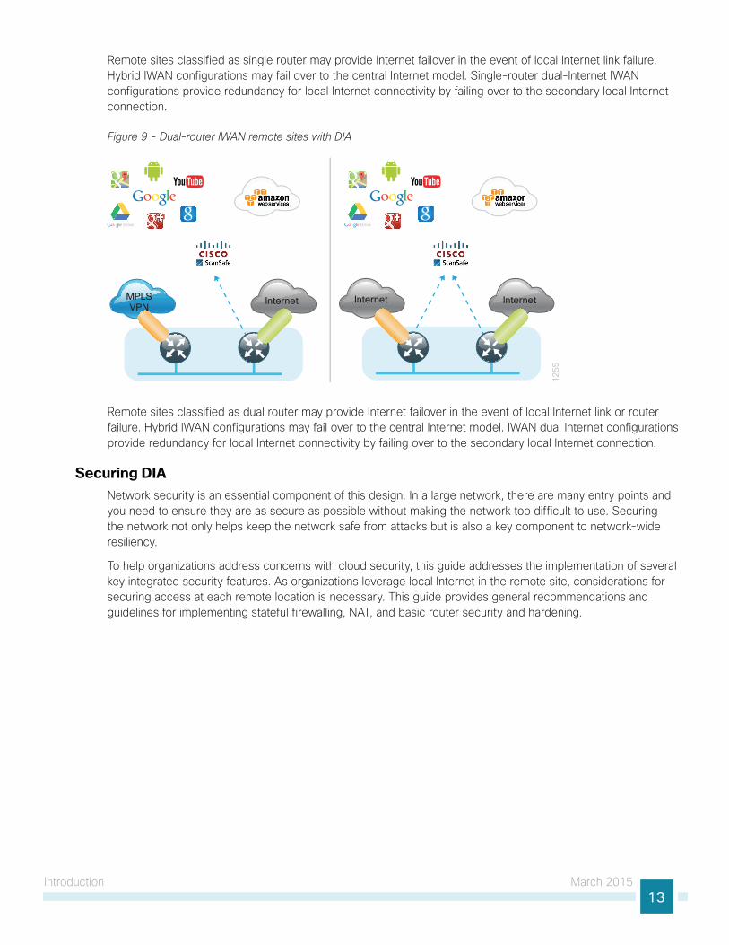
Figure 9 - Dual-router IWAN remote sites with DIA
InternetMPLSVPN
Internet
12
55
Internet
Remote sites classified as dual router may provide Internet failover in the event of local Internet link or router failure. Hybrid IWAN configurations may fail over to the central Internet model. IWAN dual Internet configurations provide redundancy for local Internet connectivity by failing over to the secondary local Internet connection.
Securing DIA Network security is an essential component of this design. In a large network, there are many entry points and you need to ensure they are as secure as possible without making the network too difficult to use. Securing the network not only helps keep the network safe from attacks but is also a key component to network-wide resiliency.
To help organizations address concerns with cloud security, this guide addresses the implementation of several key integrated security features. As organizations leverage local Internet in the remote site, considerations for securing access at each remote location is necessary. This guide provides general recommendations and guidelines for implementing stateful firewalling, NAT, and basic router security and hardening.
Introduction March 201514
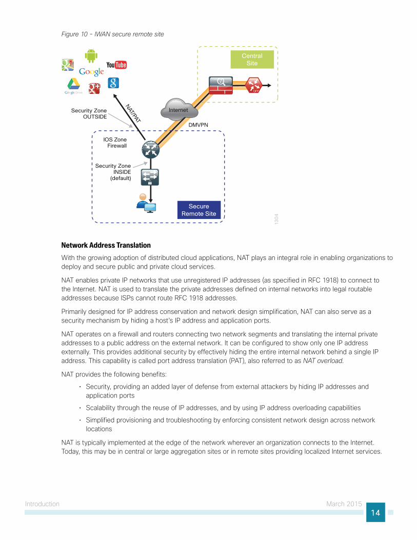
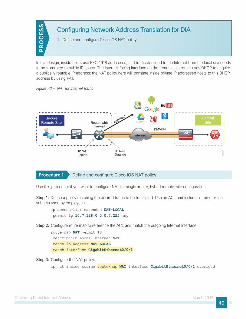
Figure 10 - IWAN secure remote site
13
04
Internet
CentralSite
SecureRemote Site
IOS ZoneFirewall
DMVPN
Security ZoneOUTSIDE
Security ZoneINSIDE
(default)
NAT/PAT
Network Address TranslationWith the growing adoption of distributed cloud applications, NAT plays an integral role in enabling organizations to deploy and secure public and private cloud services.
NAT enables private IP networks that use unregistered IP addresses (as specified in RFC 1918) to connect to the Internet. NAT is used to translate the private addresses defined on internal networks into legal routable addresses because ISPs cannot route RFC 1918 addresses.
Primarily designed for IP address conservation and network design simplification, NAT can also serve as a security mechanism by hiding a host’s IP address and application ports.
NAT operates on a firewall and routers connecting two network segments and translating the internal private addresses to a public address on the external network. It can be configured to show only one IP address externally. This provides additional security by effectively hiding the entire internal network behind a single IP address. This capability is called port address translation (PAT), also referred to as NAT overload.
NAT provides the following benefits:
• Security, providing an added layer of defense from external attackers by hiding IP addresses and application ports
• Scalability through the reuse of IP addresses, and by using IP address overloading capabilities
• Simplified provisioning and troubleshooting by enforcing consistent network design across network locations
NAT is typically implemented at the edge of the network wherever an organization connects to the Internet. Today, this may be in central or large aggregation sites or in remote sites providing localized Internet services.
Introduction March 201515
Cisco IOS Zone-Based FirewallWith the adoption of remote-site local Internet for user web browsing and cloud services, the deployment of firewall services at the remote office Internet edge is critical to maintaining an organization’s security posture.
Zone-based firewall (ZBFW), also called zone policy firewall, is a Cisco IOS-integrated stateful firewall implemented on the Cisco Integrated Services Routers (ISR) and Cisco Aggregation Services Routers (ASR) routing platforms.
Firewall zone policies are configured by using the Cisco Common Classification Policy Language (C3PL), which employs a hierarchical structure to define inspection for network protocols and the groups to which the inspection will be applied. Users familiar with the Cisco IOS modular quality of service CLI (MQC) will recognize the use of class maps to specify which traffic will be affected by the action applied in a policy map.
Within this model, router interfaces are assigned to security zones, which establish the security borders of your network. A security zone defines a boundary where traffic is subjected to policy restrictions; this policy is called a zone policy. Zone policies define what traffic is allowed to flow between security zones. Zone policies are unidirectional firewall policies applied between two security zones, called a zone pair. A zone pair is defined as two security zones between which a zone policy is applied.
Router interfaces assigned to configured security zones are subject to the default policies and rules:
• An interface can be a member of only a single security zone.
• A security zone can contain only member interfaces that are all in the same virtual routing and forwarding (VRF); interfaces in different VRFs may not be part of the same security zone.
• When an interface is placed into a security zone, traffic is implicitly allowed to flow between other interfaces assigned to the same security zone.
• Traffic flow to interfaces in different security zones is denied with an implicit deny all zone policy.
• Traffic cannot flow between an interface that is a member of a security zone and any interface that is not a member of a security zone. Instead, the traffic is dropped. If the default zone configuration is implemented as is described in this guide, traffic can flow between interfaces without security zone configurations because all interfaces automatically become part of the default zone.
• To allow traffic to flow between different security zones, policies must be configured between any two security zones.
• Pass, inspect, and drop actions can only be applied between two zones.
• By default, traffic (for instance, a routing protocol) that flows to and from the router itself is permitted. The router (as a source and destination) is defined as the self-zone by the Cisco IOS firewall. Traffic to and from the self-zone on any interface is allowed until traffic is explicitly denied by a user-defined zone security policy.
Direct Internet Access Design March 201516
Direct Internet Access Design
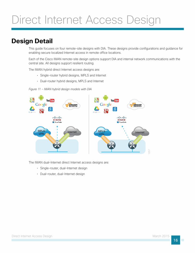
Design DetailThis guide focuses on four remote-site designs with DIA. These designs provide configurations and guidance for enabling secure localized Internet access in remote office locations.
Each of the Cisco IWAN remote-site design options support DIA and internal network communications with the central site. All designs support resilient routing.
The IWAN hybrid direct Internet access designs are:
• Single-router hybrid designs, MPLS and Internet
• Dual-router hybrid designs, MPLS and Internet
Figure 11 - IWAN hybrid design models with DIA
MPLSVPN
Internet MPLSVPN
Internet
12
57
The IWAN dual-Internet direct Internet access designs are:
• Single-router, dual-Internet design
• Dual-router, dual-Internet design
Direct Internet Access Design March 201517
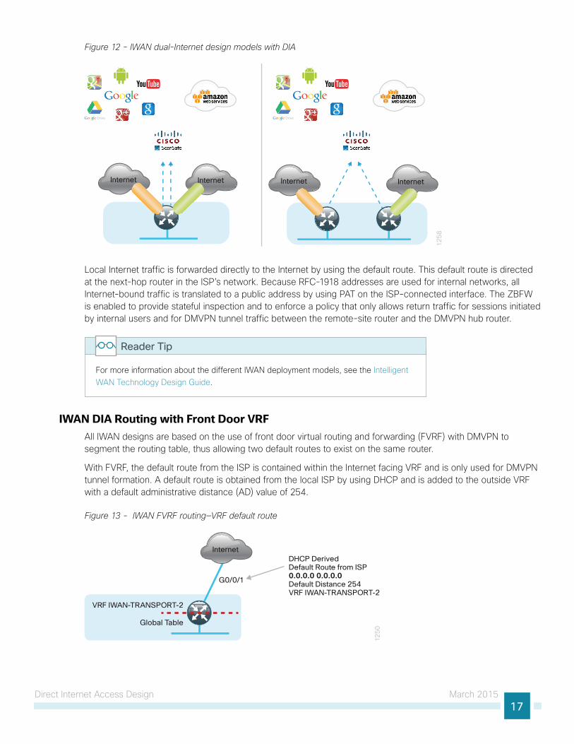
Figure 12 - IWAN dual-Internet design models with DIA
InternetInternet
12
58
Internet Internet
Local Internet traffic is forwarded directly to the Internet by using the default route. This default route is directed at the next-hop router in the ISP’s network. Because RFC-1918 addresses are used for internal networks, all Internet-bound traffic is translated to a public address by using PAT on the ISP-connected interface. The ZBFW is enabled to provide stateful inspection and to enforce a policy that only allows return traffic for sessions initiated by internal users and for DMVPN tunnel traffic between the remote-site router and the DMVPN hub router.
For more information about the different IWAN deployment models, see the Intelligent WAN Technology Design Guide.
Reader Tip
IWAN DIA Routing with Front Door VRF All IWAN designs are based on the use of front door virtual routing and forwarding (FVRF) with DMVPN to segment the routing table, thus allowing two default routes to exist on the same router.
With FVRF, the default route from the ISP is contained within the Internet facing VRF and is only used for DMVPN tunnel formation. A default route is obtained from the local ISP by using DHCP and is added to the outside VRF with a default administrative distance (AD) value of 254.
Figure 13 - IWAN FVRF routing—VRF default route
12
50
Internet
VRF IWAN-TRANSPORT-2
G0/0/1
DHCP DerivedDefault Route from ISP0.0.0.0 0.0.0.0Default Distance 254VRF IWAN-TRANSPORT-2
Global Table
Direct Internet Access Design March 201518
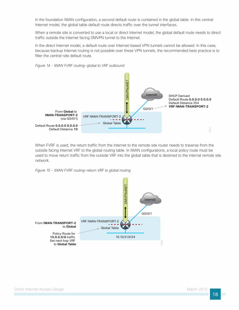
In the foundation IWAN configuration, a second default route is contained in the global table. In this central Internet model, the global table default route directs traffic over the tunnel interfaces.
When a remote site is converted to use a local or direct Internet model, the global default route needs to direct traffic outside the Internet facing DMVPN tunnel to the Internet.
In the direct Internet model, a default route over Internet-based VPN tunnels cannot be allowed. In this case, because backup Internet routing is not possible over these VPN tunnels, the recommended best practice is to filter the central-site default route.
Figure 14 - IWAN FVRF routing—global to VRF outbound
12
51
Internet
G0/0/1
DHCP DerivedDefault Route 0.0.0.0 0.0.0.0Default Distance 254VRF IWAN-TRANSPORT-2
From Global to IWAN-TRANSPORT-2
(via G0/0/1)
Default Route 0.0.0.0 0.0.0.0Default Distance 10
DM
VP
No
INE
T
VRF IWAN-TRANSPORT-2
Global Table
When FVRF is used, the return traffic from the Internet to the remote site router needs to traverse from the outside facing Internet VRF to the global routing table. In IWAN configurations, a local policy route must be used to move return traffic from the outside VRF into the global table that is destined to the internal remote site network.
Figure 15 - IWAN FVRF routing—return VRF to global routing
12
52
Internet
G0/0/1
From IWAN-TRANSPORT-2to Global
Policy Route for 10.0.0.0/8 traffic Set next-hop VRF
to Global Table
DM
VP
No
INE
T
VRF IWAN-TRANSPORT-2
Global Table
10.10.31.0/24
Direct Internet Access Design March 201519
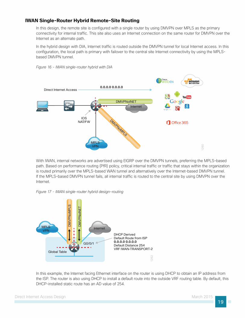
IWAN Single-Router Hybrid Remote-Site RoutingIn this design, the remote site is configured with a single router by using DMVPN over MPLS as the primary connectivity for internal traffic. This site also uses an Internet connection on the same router for DMVPN over the Internet as an alternate path.
In the hybrid design with DIA, Internet traffic is routed outside the DMVPN tunnel for local Internet access. In this configuration, the local path is primary with failover to the central site Internet connectivity by using the MPLS-based DMVPN tunnel.
Figure 16 - IWAN single-router hybrid with DIA
12
60
Direct Internet Access0.0.0.0 0.0.0.0
DMVPNoM
PLS
MPLSVPN
IOSNAT/FW
DMVPNoINET
Ciscowebex
Internet
With IWAN, internal networks are advertised using EIGRP over the DMVPN tunnels, preferring the MPLS-based path. Based on performance routing (PfR) policy, critical internal traffic or traffic that stays within the organization is routed primarily over the MPLS-based WAN tunnel and alternatively over the Internet-based DMVPN tunnel. If the MPLS-based DMVPN tunnel fails, all internal traffic is routed to the central site by using DMVPN over the Internet.
Figure 17 - IWAN single-router hybrid design—routing
Global Table
12
62
Internet
G0/0/1
DHCP DerivedDefault Route from ISP0.0.0.0 0.0.0.0Default Distance 254VRF IWAN-TRANSPORT-2
MPLSVPN
DM
VP
No
INE
T
DM
VP
No
MP
LS
In this example, the Internet facing Ethernet interface on the router is using DHCP to obtain an IP address from the ISP. The router is also using DHCP to install a default route into the outside VRF routing table. By default, this DHCP-installed static route has an AD value of 254.
Direct Internet Access Design March 201520
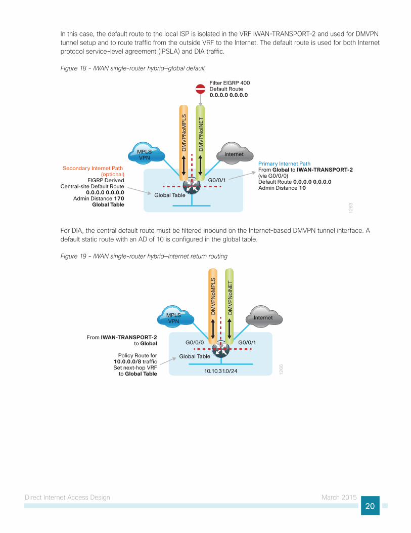
In this case, the default route to the local ISP is isolated in the VRF IWAN-TRANSPORT-2 and used for DMVPN tunnel setup and to route traffic from the outside VRF to the Internet. The default route is used for both Internet protocol service-level agreement (IPSLA) and DIA traffic.
Figure 18 - IWAN single-router hybrid—global default
Global Table
12
63
Internet
G0/0/1
Filter EIGRP 400Default Route0.0.0.0 0.0.0.0
MPLSVPN
DM
VP
No
INE
T
DM
VP
No
MP
LS
Primary Internet PathFrom Global to IWAN-TRANSPORT-2(via G0/0/0)Default Route 0.0.0.0 0.0.0.0Admin Distance 10
Secondary Internet Path (optional)
EIGRP DerivedCentral-site Default Route
0.0.0.0 0.0.0.0Admin Distance 170
Global Table
For DIA, the central default route must be filtered inbound on the Internet-based DMVPN tunnel interface. A default static route with an AD of 10 is configured in the global table.
Figure 19 - IWAN single-router hybrid—Internet return routing
10.10.31.0/24 12
66
InternetMPLSVPN
DM
VP
No
INE
T
DM
VP
No
MP
LS
From IWAN-TRANSPORT-2 to Global
Policy Route for 10.0.0.0/8 traffic Set next-hop VRF
to Global Table
G0/0/0
Global Table
G0/0/1
Direct Internet Access Design March 201521
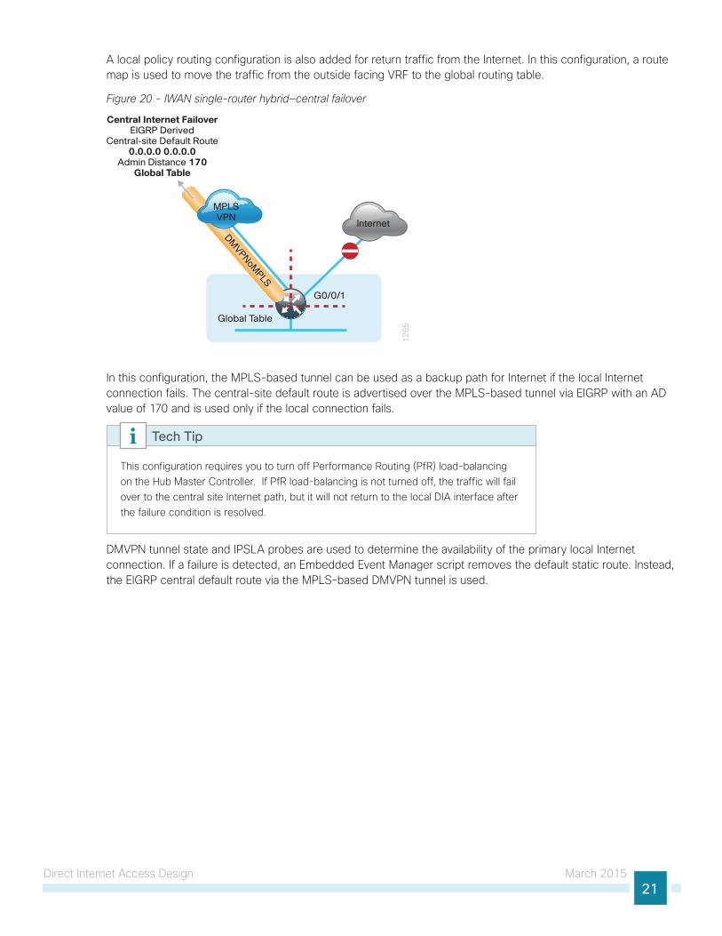
A local policy routing configuration is also added for return traffic from the Internet. In this configuration, a route map is used to move the traffic from the outside facing VRF to the global routing table.
Figure 20 - IWAN single-router hybrid—central failover
12
65
Internet
Central Internet FailoverEIGRP Derived
Central-site Default Route0.0.0.0 0.0.0.0
Admin Distance 170Global Table
MPLSVPN
DMVPNoM
PLS
Global Table
G0/0/1
In this configuration, the MPLS-based tunnel can be used as a backup path for Internet if the local Internet connection fails. The central-site default route is advertised over the MPLS-based tunnel via EIGRP with an AD value of 170 and is used only if the local connection fails.
This configuration requires you to turn off Performance Routing (PfR) load-balancing on the Hub Master Controller. If PfR load-balancing is not turned off, the traffic will fail over to the central site Internet path, but it will not return to the local DIA interface after the failure condition is resolved.
Tech Tip
DMVPN tunnel state and IPSLA probes are used to determine the availability of the primary local Internet connection. If a failure is detected, an Embedded Event Manager script removes the default static route. Instead, the EIGRP central default route via the MPLS-based DMVPN tunnel is used.
Direct Internet Access Design March 201522
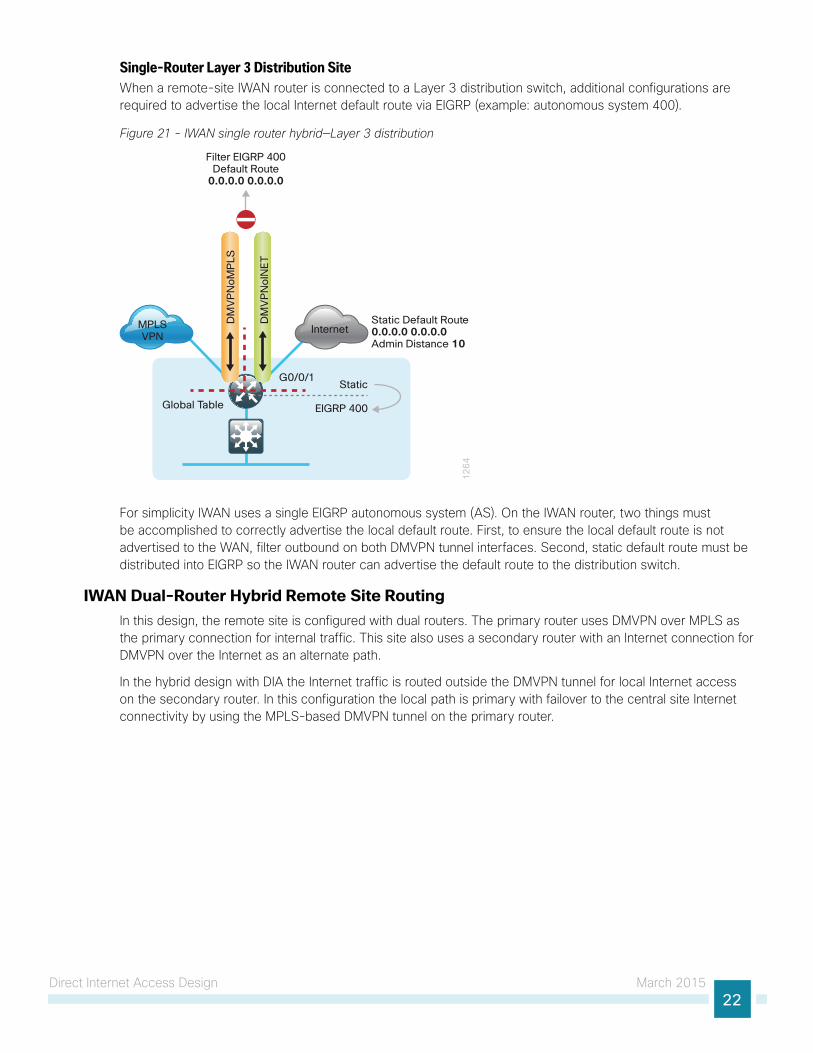
Single-Router Layer 3 Distribution SiteWhen a remote-site IWAN router is connected to a Layer 3 distribution switch, additional configurations are required to advertise the local Internet default route via EIGRP (example: autonomous system 400).
Figure 21 - IWAN single router hybrid—Layer 3 distribution
12
64
Internet
Filter EIGRP 400Default Route
0.0.0.0 0.0.0.0
MPLSVPN
DM
VP
No
INE
T
DM
VP
No
MP
LS
Static Default Route 0.0.0.0 0.0.0.0Admin Distance 10
Static
EIGRP 400Global Table
G0/0/1
For simplicity IWAN uses a single EIGRP autonomous system (AS). On the IWAN router, two things must be accomplished to correctly advertise the local default route. First, to ensure the local default route is not advertised to the WAN, filter outbound on both DMVPN tunnel interfaces. Second, static default route must be distributed into EIGRP so the IWAN router can advertise the default route to the distribution switch.
IWAN Dual-Router Hybrid Remote Site RoutingIn this design, the remote site is configured with dual routers. The primary router uses DMVPN over MPLS as the primary connection for internal traffic. This site also uses a secondary router with an Internet connection for DMVPN over the Internet as an alternate path.
In the hybrid design with DIA the Internet traffic is routed outside the DMVPN tunnel for local Internet access on the secondary router. In this configuration the local path is primary with failover to the central site Internet connectivity by using the MPLS-based DMVPN tunnel on the primary router.
Direct Internet Access Design March 201523
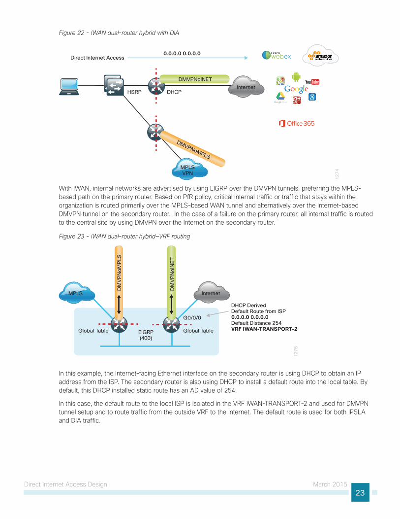
Figure 22 - IWAN dual-router hybrid with DIA
12
74
Direct Internet Access0.0.0.0 0.0.0.0
HSRP
DMVPNoINET
DMVPNoMPLS
DHCP
MPLSVPN
Internet
Ciscowebex
With IWAN, internal networks are advertised by using EIGRP over the DMVPN tunnels, preferring the MPLS-based path on the primary router. Based on PfR policy, critical internal traffic or traffic that stays within the organization is routed primarily over the MPLS-based WAN tunnel and alternatively over the Internet-based DMVPN tunnel on the secondary router. In the case of a failure on the primary router, all internal traffic is routed to the central site by using DMVPN over the Internet on the secondary router.
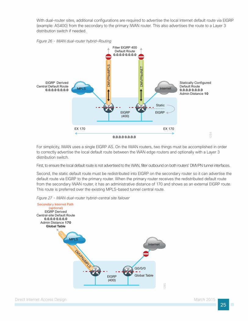
Figure 23 - IWAN dual-router hybrid—VRF routing
12
76
InternetMPLS
DM
VP
No
INE
T
DM
VP
No
MP
LS
EIGRP(400)
DHCP DerivedDefault Route from ISP0.0.0.0 0.0.0.0Default Distance 254VRF IWAN-TRANSPORT-2Global Table
G0/0/0
Global Table
In this example, the Internet-facing Ethernet interface on the secondary router is using DHCP to obtain an IP address from the ISP. The secondary router is also using DHCP to install a default route into the local table. By default, this DHCP installed static route has an AD value of 254.
In this case, the default route to the local ISP is isolated in the VRF IWAN-TRANSPORT-2 and used for DMVPN tunnel setup and to route traffic from the outside VRF to the Internet. The default route is used for both IPSLA and DIA traffic.

Direct Internet Access Design March 201524
Figure 24 - IWAN dual-router hybrid—global default
12
78
InternetMPLS
DM
VP
No
INE
T
DM
VP
No
MP
LS
EIGRP(400)
Global Table
G0/0/0
Global Table
Secondary Internet Path(optional)
EIGRP DerivedCentral-site Default Route
0.0.0.0 0.0.0.0
Admin Distance 170Global Table
Primary Internet PathFrom Global toIWAN-TRANSPORT-2(via G0/0/0)
Default Route 0.0.0.0 0.0.0.0Admin Distance 10
Filter EIGRP 400Default Route0.0.0.0 0.0.0.0
For DIA, the central default route must be filtered inbound on the Internet-based DMVPN tunnel interface on the secondary router. A default static route with an administrative distance of 10 is also configured in the global table on the secondary router.
Figure 25 - IWAN dual-router hybrid—Internet return routing
12
79
InternetMPLS
DM
VP
No
INE
T
DM
VP
No
MP
LS
EIGRP(400)
G0/0/0
Global Table
From IWAN-TRANSPORT-2 to Global
Policy Route for 10.0.0.0/8 traffic Set next-hop VRF to Global Table
10.7.112.0/24
A local policy routing configuration is also added to the secondary router for return traffic from the Internet. In this configuration a route map is used to move the traffic from the outside facing VRF to the global routing table.
Direct Internet Access Design March 201525
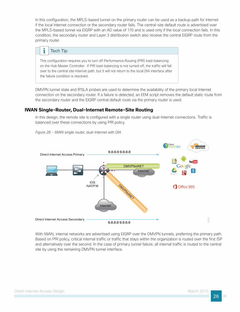
With dual-router sites, additional configurations are required to advertise the local Internet default route via EIGRP (example: AS400) from the secondary to the primary IWAN router. This also advertises the route to a Layer 3 distribution switch if needed.
Figure 26 - IWAN dual-router hybrid—Routing
12
84
InternetMPLS
DM
VP
No
INE
T
DM
VP
No
MP
LSEIGRP(400)
Static
EIGRP
Statically ConfiguredDefault Route0.0.0.0 0.0.0.0Admin Distance 10
EIGRP DerivedCentral Default Route
0.0.0.0 0.0.0.0
Filter EIGRP 400Default Route
0.0.0.0 0.0.0.0
0.0.0.0 0.0.0.0
EX 170 EX 170
For simplicity, IWAN uses a single EIGRP AS. On the IWAN routers, two things must be accomplished in order to correctly advertise the local default route between the WAN edge routers and optionally with a Layer 3 distribution switch.
First, to ensure the local default route is not advertised to the WAN, filter outbound on both routers’ DMVPN tunnel interfaces.
Second, the static default route must be redistributed into EIGRP on the secondary router so it can advertise the default route via EIGRP to the primary router. When the primary router receives the redistributed default route from the secondary IWAN router, it has an administrative distance of 170 and shows as an external EIGRP route. This route is preferred over the existing MPLS-based tunnel central route.
Figure 27 - IWAN dual-router hybrid—central site failover
Internet
12
85
Secondary Internet Path (optional)
EIGRP DerivedCentral-site Default Route
0.0.0.0 0.0.0.0Admin Distance 170
Global Table
MPLS
DMVPNoM
PLS
G0/0/0
Global TableEIGRP(400)
Direct Internet Access Design March 201526
In this configuration, the MPLS-based tunnel on the primary router can be used as a backup path for Internet if the local Internet connection or the secondary router fails. The central-site default route is advertised over the MPLS-based tunnel via EIGRP with an AD value of 170 and is used only if the local connection fails. In this condition, the secondary router and Layer 3 distribution switch also receive the central EIGRP route from the primary router.
This configuration requires you to turn off Performance Routing (PfR) load-balancing on the Hub Master Controller. If PfR load-balancing is not turned off, the traffic will fail over to the central site Internet path, but it will not return to the local DIA interface after the failure condition is resolved.
Tech Tip
DMVPN tunnel state and IPSLA probes are used to determine the availability of the primary local Internet connection on the secondary router. If a failure is detected, an EEM script removes the default static route from the secondary router and the EIGRP central default route via the primary router is used.
IWAN Single-Router, Dual-Internet Remote-Site RoutingIn this design, the remote site is configured with a single router using dual-Internet connections. Traffic is balanced over these connections by using PfR policy.
Figure 28 - IWAN single router, dual-Internet with DIA
12
67
Direct Internet Access Primary0.0.0.0 0.0.0.0
DMVPNoINET
IOSNAT/FW
DMVPNoINET
Ciscowebex
Internet
Direct Internet Access Secondary0.0.0.0 0.0.0.0
Internet
With IWAN, internal networks are advertised using EIGRP over the DMVPN tunnels, preferring the primary path. Based on PfR policy, critical internal traffic or traffic that stays within the organization is routed over the first ISP and alternatively over the second. In the case of primary tunnel failure, all internal traffic is routed to the central site by using the remaining DMVPN tunnel interface.
Direct Internet Access Design March 201527
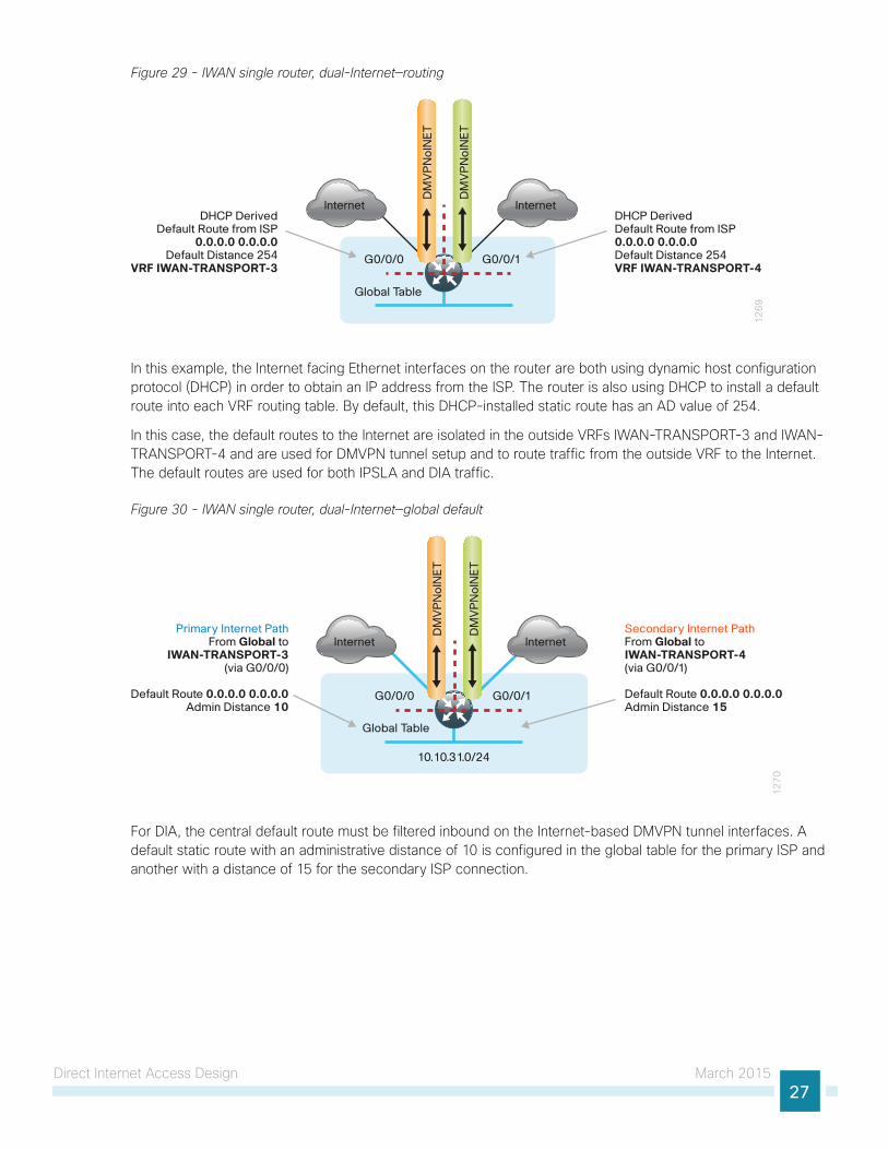
Figure 29 - IWAN single router, dual-Internet—routing
Global Table
12
69
Internet
DM
VP
No
INE
T
DM
VP
No
INE
T
DHCP DerivedDefault Route from ISP0.0.0.0 0.0.0.0Default Distance 254VRF IWAN-TRANSPORT-4
DHCP DerivedDefault Route from ISP
0.0.0.0 0.0.0.0Default Distance 254
VRF IWAN-TRANSPORT-3
Internet
G0/0/0 G0/0/1
In this example, the Internet facing Ethernet interfaces on the router are both using dynamic host configuration protocol (DHCP) in order to obtain an IP address from the ISP. The router is also using DHCP to install a default route into each VRF routing table. By default, this DHCP-installed static route has an AD value of 254.
In this case, the default routes to the Internet are isolated in the outside VRFs IWAN-TRANSPORT-3 and IWAN-TRANSPORT-4 and are used for DMVPN tunnel setup and to route traffic from the outside VRF to the Internet. The default routes are used for both IPSLA and DIA traffic.
Figure 30 - IWAN single router, dual-Internet—global default
10.10.31.0/24
12
70
Internet
DM
VP
No
INE
T
DM
VP
No
INE
T
Secondary Internet PathFrom Global to IWAN-TRANSPORT-4(via G0/0/1)
Default Route 0.0.0.0 0.0.0.0Admin Distance 15
Primary Internet PathFrom Global to
IWAN-TRANSPORT-3(via G0/0/0)
Default Route 0.0.0.0 0.0.0.0Admin Distance 10
Internet
G0/0/0 G0/0/1
Global Table
For DIA, the central default route must be filtered inbound on the Internet-based DMVPN tunnel interfaces. A default static route with an administrative distance of 10 is configured in the global table for the primary ISP and another with a distance of 15 for the secondary ISP connection.
Direct Internet Access Design March 201528
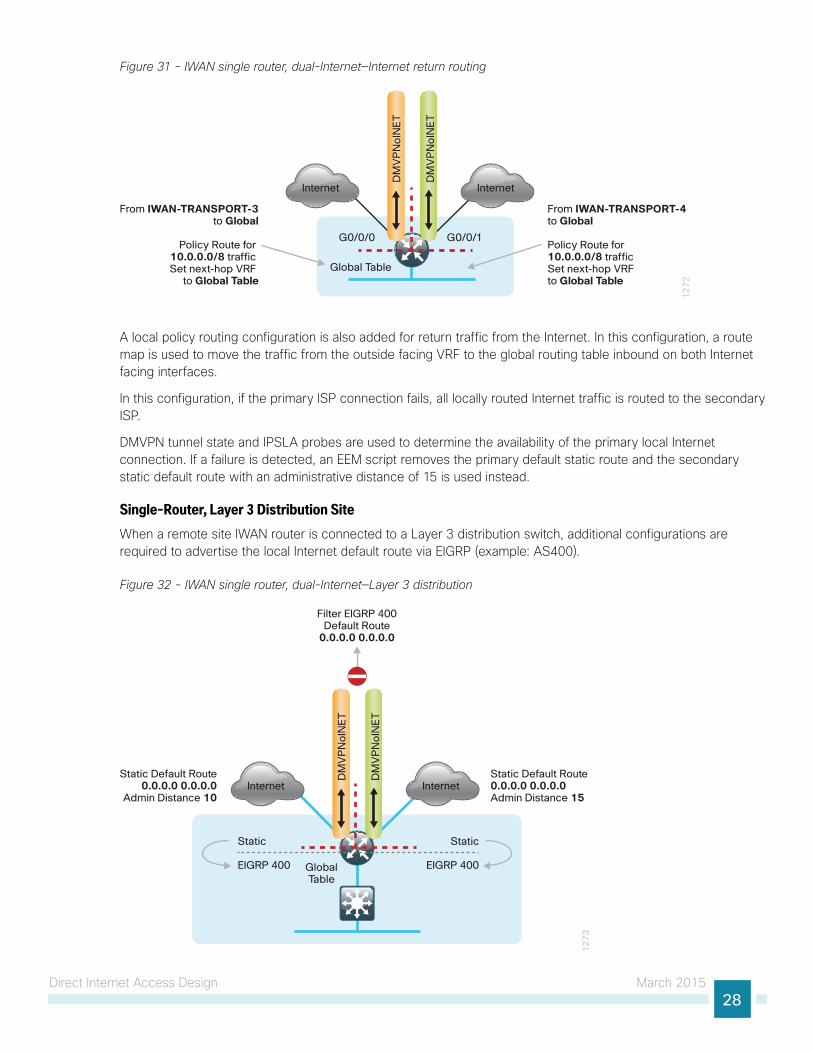
Figure 31 - IWAN single router, dual-Internet—Internet return routing
Global Table
12
72
Internet
DM
VP
No
INE
T
DM
VP
No
INE
T
From IWAN-TRANSPORT-4to Global
Policy Route for 10.0.0.0/8 traffic Set next-hop VRF to Global Table
From IWAN-TRANSPORT-3to Global
Policy Route for 10.0.0.0/8 traffic Set next-hop VRF
to Global Table
Internet
G0/0/0 G0/0/1
A local policy routing configuration is also added for return traffic from the Internet. In this configuration, a route map is used to move the traffic from the outside facing VRF to the global routing table inbound on both Internet facing interfaces.
In this configuration, if the primary ISP connection fails, all locally routed Internet traffic is routed to the secondary ISP.
DMVPN tunnel state and IPSLA probes are used to determine the availability of the primary local Internet connection. If a failure is detected, an EEM script removes the primary default static route and the secondary static default route with an administrative distance of 15 is used instead.
Single-Router, Layer 3 Distribution SiteWhen a remote site IWAN router is connected to a Layer 3 distribution switch, additional configurations are required to advertise the local Internet default route via EIGRP (example: AS400).
Figure 32 - IWAN single router, dual-Internet—Layer 3 distribution1
27
3
Internet
Filter EIGRP 400Default Route
0.0.0.0 0.0.0.0
DM
VP
No
INE
T
DM
VP
No
INE
T
Static Default Route 0.0.0.0 0.0.0.0Admin Distance 15
Static
EIGRP 400GlobalTable
Static
EIGRP 400
InternetStatic Default Route
0.0.0.0 0.0.0.0Admin Distance 10
Direct Internet Access Design March 201529
For simplicity, IWAN uses a single EIGRP AS. On the IWAN router, two things must be accomplished to correctly advertise the local default route. First, to ensure the local default route is not advertised to the WAN, filter outbound on both DMVPN tunnel interfaces. Second, redistribute the static default routes into EIGRP so the IWAN router can advertise the default route to the distribution switch.
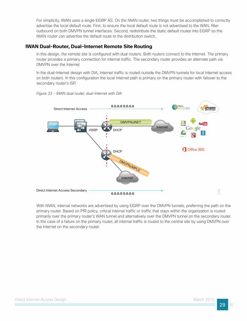
IWAN Dual-Router, Dual-Internet Remote Site RoutingIn this design, the remote site is configured with dual routers. Both routers connect to the Internet. The primary router provides a primary connection for internal traffic. The secondary router provides an alternate path via DMVPN over the Internet.
In the dual-Internet design with DIA, Internet traffic is routed outside the DMVPN tunnels for local Internet access on both routers. In this configuration the local Internet path is primary on the primary router with failover to the secondary router’s ISP.
Figure 33 - IWAN dual router, dual-Internet with DIA
12
86
Direct Internet Access0.0.0.0 0.0.0.0
HSRP
DMVPNoINET
DMVPNoMPLS
DHCPInternet
Ciscowebex
Internet
DHCP
Direct Internet Access Secondary0.0.0.0 0.0.0.0
With IWAN, internal networks are advertised by using EIGRP over the DMVPN tunnels, preferring the path on the primary router. Based on PfR policy, critical internal traffic or traffic that stays within the organization is routed primarily over the primary router’s WAN tunnel and alternatively over the DMVPN tunnel on the secondary router. In the case of a failure on the primary router, all internal traffic is routed to the central site by using DMVPN over the Internet on the secondary router.
Direct Internet Access Design March 201530
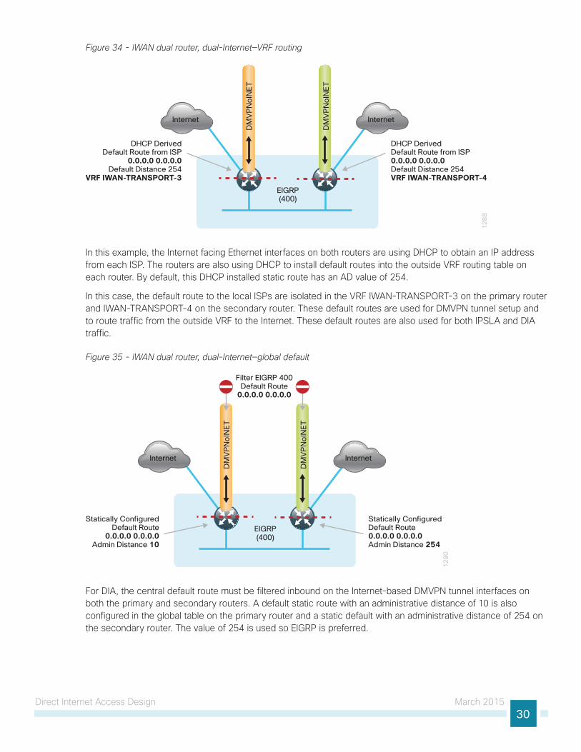
Figure 34 - IWAN dual router, dual-Internet—VRF routing
12
88
Internet
DM
VP
No
INE
T
DM
VP
No
INE
T
EIGRP(400)
Internet
DHCP DerivedDefault Route from ISP0.0.0.0 0.0.0.0Default Distance 254VRF IWAN-TRANSPORT-4
DHCP DerivedDefault Route from ISP
0.0.0.0 0.0.0.0Default Distance 254
VRF IWAN-TRANSPORT-3
In this example, the Internet facing Ethernet interfaces on both routers are using DHCP to obtain an IP address from each ISP. The routers are also using DHCP to install default routes into the outside VRF routing table on each router. By default, this DHCP installed static route has an AD value of 254.
In this case, the default route to the local ISPs are isolated in the VRF IWAN-TRANSPORT-3 on the primary router and IWAN-TRANSPORT-4 on the secondary router. These default routes are used for DMVPN tunnel setup and to route traffic from the outside VRF to the Internet. These default routes are also used for both IPSLA and DIA traffic.
Figure 35 - IWAN dual router, dual-Internet—global default
12
90
Internet
DM
VP
No
INE
T
DM
VP
No
INE
T
EIGRP(400)
Internet
Statically ConfiguredDefault Route0.0.0.0 0.0.0.0Admin Distance 254
Statically ConfiguredDefault Route
0.0.0.0 0.0.0.0Admin Distance 10
Filter EIGRP 400Default Route
0.0.0.0 0.0.0.0
For DIA, the central default route must be filtered inbound on the Internet-based DMVPN tunnel interfaces on both the primary and secondary routers. A default static route with an administrative distance of 10 is also configured in the global table on the primary router and a static default with an administrative distance of 254 on the secondary router. The value of 254 is used so EIGRP is preferred.
Direct Internet Access Design March 201531
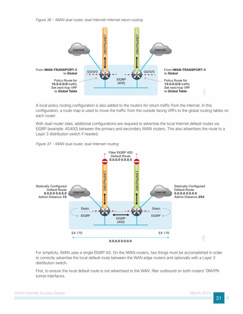
Figure 36 - IWAN dual router, dual-Internet—Internet return routing
12
91
Internet
DM
VP
No
INE
T
DM
VP
No
INE
T
EIGRP(400)
Internet
From IWAN-TRANSPORT-4 to Global
Policy Route for 10.0.0.0/8 traffic Set next-hop VRF to Global Table
From IWAN-TRANSPORT-3to Global
Policy Route for10.0.0.0/8 trafficSet next-hop VRF
to Global Table
G0/0/0 G0/0/0
A local policy routing configuration is also added to the routers for return traffic from the Internet. In this configuration, a route map is used to move the traffic from the outside facing VRFs to the global routing tables on each router.
With dual-router sites, additional configurations are required to advertise the local Internet default routes via EIGRP (example: AS400) between the primary and secondary IWAN routers. This also advertises the route to a Layer 3 distribution switch if needed.
Figure 37 - IWAN dual router, dual-Internet—routing
12
96
Internet
DM
VP
No
INE
T
DM
VP
No
INE
T
EIGRP(400)
Internet
Static
EIGRP
Static
EIGRP
Statically ConfiguredDefault Route0.0.0.0 0.0.0.0Admin Distance 254
Statically ConfiguredDefault Route
0.0.0.0 0.0.0.0Admin Distance 10
Filter EIGRP 400Default Route
0.0.0.0 0.0.0.0
0.0.0.0 0.0.0.0
EX 170 EX 170
For simplicity, IWAN uses a single EIGRP AS. On the IWAN routers, two things must be accomplished in order to correctly advertise the local default route between the WAN edge routers and optionally with a Layer 3 distribution switch.
First, to ensure the local default route is not advertised to the WAN, filter outbound on both routers’ DMVPN tunnel interfaces.
Direct Internet Access Design March 201532
Second, redistribute the static default route into EIGRP on both the primary and secondary routers so they can advertise the default route via EIGRP between them and with a Layer 3 distribution switch.
The primary router advertises the redistributed static default route to the secondary router and distribution switch with an administrative distance of 170; this will be preferred over the static default route configured on the secondary router with a distance of 254. The secondary router also advertises a redistributed default static route to the primary router and distribution switch with a less preferred EIGRP metric.
In this configuration, the DMVPN tunnel on the secondary router can be used as a backup path for Internet if the local Internet connection or the primary router fails. In the case of a primary ISP failure, the secondary router advertises the secondary ISP default with an administrative distance of 170 via EIGRP and becomes the Internet path for the remote site network.
DMVPN tunnel state and IPSLA probes are used to determine the availability of the primary router’s local Internet connection. If a failure is detected, an EEM script removes the default static route from the primary router and the redistributed static route on the secondary router via EIGRP is used instead.
Deploying Direct Internet Access March 201533
Deploying Direct Internet Access
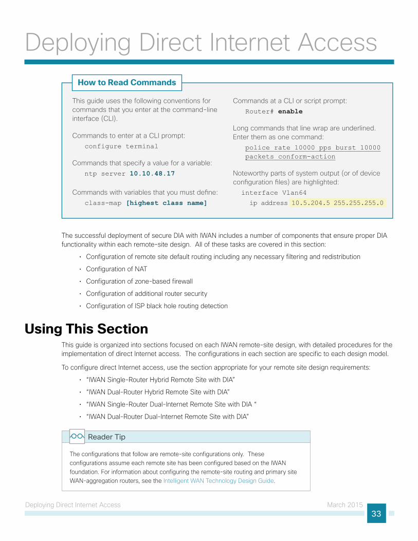
This guide uses the following conventions for commands that you enter at the command-line interface (CLI).
Commands to enter at a CLI prompt: configure terminal
Commands that specify a value for a variable: ntp server 10.10.48.17
Commands with variables that you must de�ne: class-map [highest class name]
Commands at a CLI or script prompt: Router# enable
Long commands that line wrap are underlined. Enter them as one command:
police rate 10000 pps burst 10000 packets conform-action
Noteworthy parts of system output (or of device con�guration �les) are highlighted: interface Vlan64 ip address 10.5.204.5 255.255.255.0
How to Read Commands
The successful deployment of secure DIA with IWAN includes a number of components that ensure proper DIA functionality within each remote-site design. All of these tasks are covered in this section:
• Configuration of remote site default routing including any necessary filtering and redistribution
• Configuration of NAT
• Configuration of zone-based firewall
• Configuration of additional router security
• Configuration of ISP black hole routing detection
Using This SectionThis guide is organized into sections focused on each IWAN remote-site design, with detailed procedures for the implementation of direct Internet access. The configurations in each section are specific to each design model.
To configure direct Internet access, use the section appropriate for your remote site design requirements:
• “IWAN Single-Router Hybrid Remote Site with DIA”
• “IWAN Dual-Router Hybrid Remote Site with DIA”
• “IWAN Single-Router Dual-Internet Remote Site with DIA “
• “IWAN Dual-Router Dual-Internet Remote Site with DIA”
The configurations that follow are remote-site configurations only. These configurations assume each remote site has been configured based on the IWAN foundation. For information about configuring the remote-site routing and primary site WAN-aggregation routers, see the Intelligent WAN Technology Design Guide.
Reader Tip
Deploying Direct Internet Access March 201534
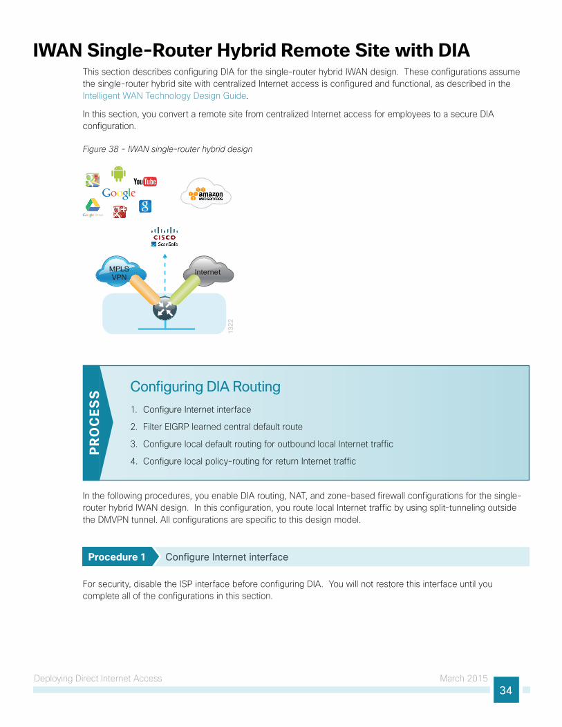
IWAN Single-Router Hybrid Remote Site with DIAThis section describes configuring DIA for the single-router hybrid IWAN design. These configurations assume the single-router hybrid site with centralized Internet access is configured and functional, as described in the Intelligent WAN Technology Design Guide.
In this section, you convert a remote site from centralized Internet access for employees to a secure DIA configuration.
Figure 38 - IWAN single-router hybrid design
MPLSVPN
Internet
13
22
Configuring DIA Routing
1. Configure Internet interface
2. Filter EIGRP learned central default route
3. Configure local default routing for outbound local Internet traffic
4. Configure local policy-routing for return Internet traffic
PR
OC
ESS
In the following procedures, you enable DIA routing, NAT, and zone-based firewall configurations for the single-router hybrid IWAN design. In this configuration, you route local Internet traffic by using split-tunneling outside the DMVPN tunnel. All configurations are specific to this design model.
Procedure 1 Configure Internet interface
For security, disable the ISP interface before configuring DIA. You will not restore this interface until you complete all of the configurations in this section.
Deploying Direct Internet Access March 201535
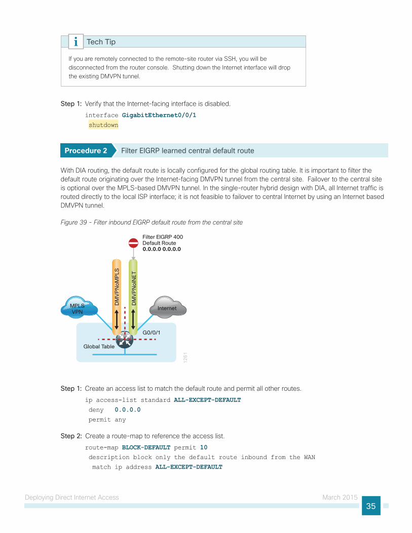
If you are remotely connected to the remote-site router via SSH, you will be disconnected from the router console. Shutting down the Internet interface will drop the existing DMVPN tunnel.
Tech Tip
Step 1: Verify that the Internet-facing interface is disabled.
interface GigabitEthernet0/0/1 shutdown
Procedure 2 Filter EIGRP learned central default route
With DIA routing, the default route is locally configured for the global routing table. It is important to filter the default route originating over the Internet-facing DMVPN tunnel from the central site. Failover to the central site is optional over the MPLS-based DMVPN tunnel. In the single-router hybrid design with DIA, all Internet traffic is routed directly to the local ISP interface; it is not feasible to failover to central Internet by using an Internet based DMVPN tunnel.
Figure 39 - Filter inbound EIGRP default route from the central site
12
61
Internet
Filter EIGRP 400Default Route0.0.0.0 0.0.0.0
MPLSVPN
DM
VP
No
INE
T
DM
VP
No
MP
LS
Global Table
G0/0/1
Step 1: Create an access list to match the default route and permit all other routes.
ip access-list standard ALL-EXCEPT-DEFAULT deny 0.0.0.0 permit any
Step 2: Create a route-map to reference the access list.
route-map BLOCK-DEFAULT permit 10 description block only the default route inbound from the WAN
match ip address ALL-EXCEPT-DEFAULT
Deploying Direct Internet Access March 201536
Step 3: Apply the policy as an inbound distribute list for the Internet-facing DMVPN tunnel interface.
router eigrp IWAN-EIGRP address-family ipv4 unicast autonomous-system 400 topology base
distribute-list route-map BLOCK-DEFAULT in tunnel11exit
Step 4: If you do not want fallback to centralized Internet, also apply the policy as an inbound distribute list for the MPLS-facing DMVPN tunnel interface.
router eigrp IWAN-EIGRP address-family ipv4 unicast autonomous-system 400 topology base
distribute-list route-map BLOCK-DEFAULT in tunnel10exit
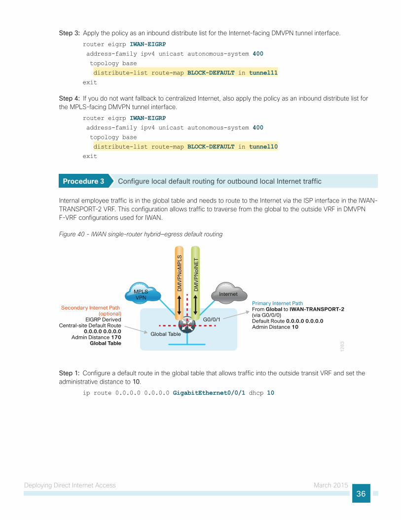
Procedure 3 Configure local default routing for outbound local Internet traffic
Internal employee traffic is in the global table and needs to route to the Internet via the ISP interface in the IWAN-TRANSPORT-2 VRF. This configuration allows traffic to traverse from the global to the outside VRF in DMVPN F-VRF configurations used for IWAN.
Figure 40 - IWAN single-router hybrid—egress default routing
Global Table
12
63
Internet
G0/0/1
MPLSVPN
DM
VP
No
INE
T
DM
VP
No
MP
LS
Primary Internet PathFrom Global to IWAN-TRANSPORT-2(via G0/0/0)Default Route 0.0.0.0 0.0.0.0Admin Distance 10
Secondary Internet Path (optional)
EIGRP DerivedCentral-site Default Route
0.0.0.0 0.0.0.0Admin Distance 170
Global Table
Step 1: Configure a default route in the global table that allows traffic into the outside transit VRF and set the administrative distance to 10.
ip route 0.0.0.0 0.0.0.0 GigabitEthernet0/0/1 dhcp 10
Deploying Direct Internet Access March 201537
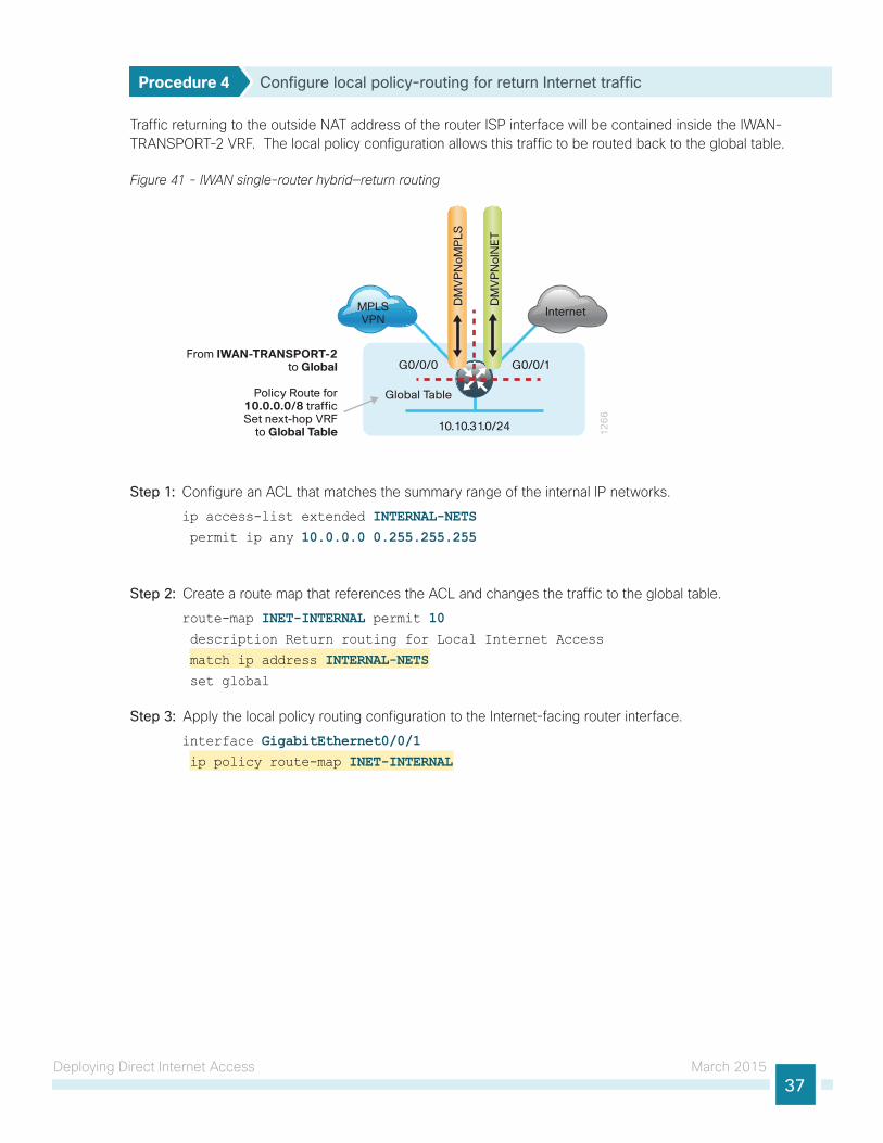
Procedure 4 Configure local policy-routing for return Internet traffic
Traffic returning to the outside NAT address of the router ISP interface will be contained inside the IWAN-TRANSPORT-2 VRF. The local policy configuration allows this traffic to be routed back to the global table.
Figure 41 - IWAN single-router hybrid—return routing
10.10.31.0/24 12
66
InternetMPLSVPN
DM
VP
No
INE
T
DM
VP
No
MP
LS
From IWAN-TRANSPORT-2 to Global
Policy Route for 10.0.0.0/8 traffic Set next-hop VRF
to Global Table
G0/0/0
Global Table
G0/0/1
Step 1: Configure an ACL that matches the summary range of the internal IP networks.
ip access-list extended INTERNAL-NETS permit ip any 10.0.0.0 0.255.255.255
Step 2: Create a route map that references the ACL and changes the traffic to the global table.
route-map INET-INTERNAL permit 10 description Return routing for Local Internet Access
match ip address INTERNAL-NETS set global
Step 3: Apply the local policy routing configuration to the Internet-facing router interface.
interface GigabitEthernet0/0/1 ip policy route-map INET-INTERNAL
Deploying Direct Internet Access March 201538
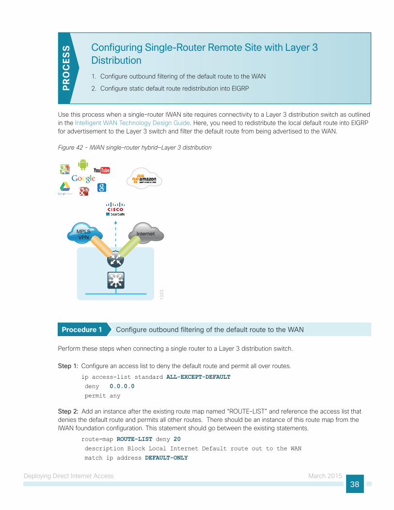
Configuring Single-Router Remote Site with Layer 3 Distribution
1. Configure outbound filtering of the default route to the WAN
2. Configure static default route redistribution into EIGRPPR
OC
ESS
Use this process when a single-router IWAN site requires connectivity to a Layer 3 distribution switch as outlined in the Intelligent WAN Technology Design Guide. Here, you need to redistribute the local default route into EIGRP for advertisement to the Layer 3 switch and filter the default route from being advertised to the WAN.
Figure 42 - IWAN single-router hybrid—Layer 3 distribution
MPLSVPN
Internet
13
23
Procedure 1 Configure outbound filtering of the default route to the WAN
Perform these steps when connecting a single router to a Layer 3 distribution switch.
Step 1: Configure an access list to deny the default route and permit all over routes.
ip access-list standard ALL-EXCEPT-DEFAULT deny 0.0.0.0 permit any
Step 2: Add an instance after the existing route map named “ROUTE-LIST” and reference the access list that denies the default route and permits all other routes. There should be an instance of this route map from the IWAN foundation configuration. This statement should go between the existing statements.
route-map ROUTE-LIST deny 20 description Block Local Internet Default route out to the WAN
match ip address DEFAULT-ONLY
Deploying Direct Internet Access March 201539
Step 3: On both routers, ensure that the route map is applied as an outbound distribution list on the DMVPN tunnel interface. Apply this as part of the foundational configuration for dual-router egress filtering.
router eigrp IWAN-EIGRP !
address-family ipv4 unicast autonomous-system 400 topology base
distribute-list route-map ROUTE-LIST out Tunnel10 distribute-list route-map ROUTE-LIST out Tunnel11 exit-af-topology
exit-address-family
Procedure 2 Configure static default route redistribution into EIGRP
Perform these steps when connecting a single router to a Layer 3 distribution switch.
Step 1: Configure an access list to match the default route for redistribution.
ip access-list standard DEFAULT-ONLY permit 0.0.0.0
Step 2: Configure a route map for static redistribution, referencing the access list that matches the static default route.
route-map STATIC-IN permit 10 description Redistribute local default route
match ip address DEFAULT-ONLY
Step 3: Redistribute the static default route installed by DHCP into EIGRP AS400 by using the route map.
router eigrp IWAN-EIGRP !
address-family ipv4 unicast autonomous-system 400 topology base
redistribute static route-map STATIC-IN exit-af-topology
exit-address-family
Deploying Direct Internet Access March 201540
Configuring Network Address Translation for DIA
1. Define and configure Cisco IOS NAT policyP
RO
CES
S
In this design, inside hosts use RFC 1918 addresses, and traffic destined to the Internet from the local site needs to be translated to public IP space. The Internet-facing interface on the remote-site router uses DHCP to acquire a publically routable IP address; the NAT policy here will translate inside private IP addressed hosts to this DHCP address by using PAT.
Figure 43 - NAT for Internet traffic
13
01
Internet
DMVPN
IP NATInside
Router withFirewall
IP NATOutside
CentralSite
SecureRemote Site NAT/PAT
Procedure 1 Define and configure Cisco IOS NAT policy
Use this procedure if you want to configure NAT for single-router, hybrid remote-site configurations.
Step 1: Define a policy matching the desired traffic to be translated. Use an ACL and include all remote-site subnets used by employees.
ip access-list extended NAT-LOCAL permit ip 10.7.128.0 0.0.7.255 any
Step 2: Configure route map to reference the ACL and match the outgoing Internet Interface.
route-map NAT permit 10 description Local Internet NAT
match ip address NAT-LOCAL match interface GigabitEthernet0/0/1
Step 3: Configure the NAT policy.
ip nat inside source route-map NAT interface GigabitEthernet0/0/1 overload
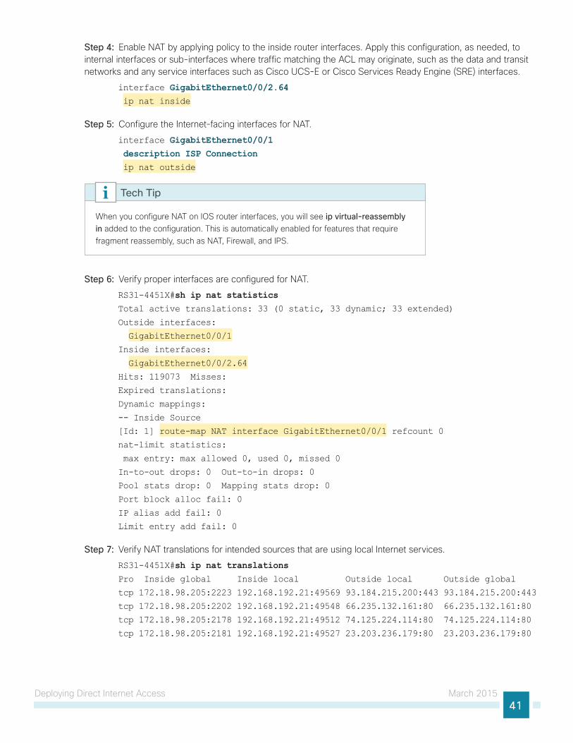
Deploying Direct Internet Access March 201541
Step 4: Enable NAT by applying policy to the inside router interfaces. Apply this configuration, as needed, to internal interfaces or sub-interfaces where traffic matching the ACL may originate, such as the data and transit networks and any service interfaces such as Cisco UCS-E or Cisco Services Ready Engine (SRE) interfaces.
interface GigabitEthernet0/0/2.64 ip nat inside
Step 5: Configure the Internet-facing interfaces for NAT.
interface GigabitEthernet0/0/1 description ISP Connection ip nat outside
When you configure NAT on IOS router interfaces, you will see ip virtual-reassembly in added to the configuration. This is automatically enabled for features that require fragment reassembly, such as NAT, Firewall, and IPS.
Tech Tip
Step 6: Verify proper interfaces are configured for NAT.
RS31-4451X#sh ip nat statistics Total active translations: 33 (0 static, 33 dynamic; 33 extended)
Outside interfaces:
GigabitEthernet0/0/1
Inside interfaces:
GigabitEthernet0/0/2.64
Hits: 119073 Misses:
Expired translations:
Dynamic mappings:
-- Inside Source
[Id: 1] route-map NAT interface GigabitEthernet0/0/1 refcount 0
nat-limit statistics:
max entry: max allowed 0, used 0, missed 0
In-to-out drops: 0 Out-to-in drops: 0
Pool stats drop: 0 Mapping stats drop: 0
Port block alloc fail: 0
IP alias add fail: 0
Limit entry add fail: 0
Step 7: Verify NAT translations for intended sources that are using local Internet services.
RS31-4451X#sh ip nat translations Pro Inside global Inside local Outside local Outside global
tcp 172.18.98.205:2223 192.168.192.21:49569 93.184.215.200:443 93.184.215.200:443
tcp 172.18.98.205:2202 192.168.192.21:49548 66.235.132.161:80 66.235.132.161:80
tcp 172.18.98.205:2178 192.168.192.21:49512 74.125.224.114:80 74.125.224.114:80
tcp 172.18.98.205:2181 192.168.192.21:49527 23.203.236.179:80 23.203.236.179:80
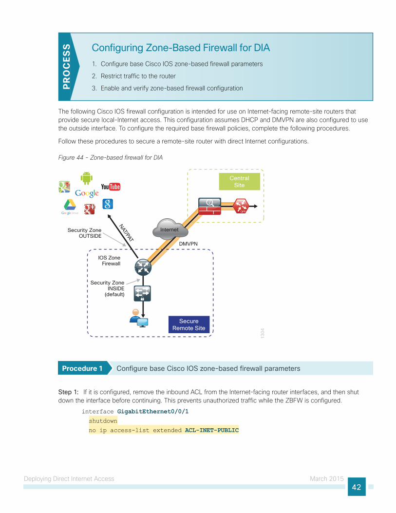
Deploying Direct Internet Access March 201542
Configuring Zone-Based Firewall for DIA
1. Configure base Cisco IOS zone-based firewall parameters
2. Restrict traffic to the router
3. Enable and verify zone-based firewall configurationPR
OC
ESS
The following Cisco IOS firewall configuration is intended for use on Internet-facing remote-site routers that provide secure local-Internet access. This configuration assumes DHCP and DMVPN are also configured to use the outside interface. To configure the required base firewall policies, complete the following procedures.
Follow these procedures to secure a remote-site router with direct Internet configurations.
Figure 44 - Zone-based firewall for DIA
13
04
Internet
CentralSite
SecureRemote Site
IOS ZoneFirewall
DMVPN
Security ZoneOUTSIDE
Security ZoneINSIDE
(default)
NAT/PAT
Procedure 1 Configure base Cisco IOS zone-based firewall parameters
Step 1: If it is configured, remove the inbound ACL from the Internet-facing router interfaces, and then shut down the interface before continuing. This prevents unauthorized traffic while the ZBFW is configured.
interface GigabitEthernet0/0/1 shutdown
no ip access-list extended ACL-INET-PUBLIC
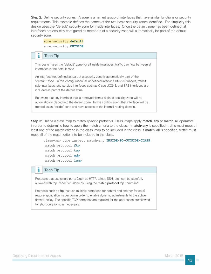
Deploying Direct Internet Access March 201543
Step 2: Define security zones. A zone is a named group of interfaces that have similar functions or security requirements. This example defines the names of the two basic security zones identified. For simplicity this design uses the “default” security zone for inside interfaces. Once the default zone has been defined, all interfaces not explicitly configured as members of a security zone will automatically be part of the default security zone.
zone security defaultzone security OUTSIDE
This design uses the “default” zone for all inside interfaces; traffic can flow between all interfaces in the default zone.
An interface not defined as part of a security zone is automatically part of the “default” zone. In this configuration, all undefined interface DMVPN tunnels, transit sub-interfaces, and service interfaces such as Cisco UCS-E, and SRE interfaces are included as part of the default zone.
Be aware that any interface that is removed from a defined security zone will be automatically placed into the default zone. In this configuration, that interface will be treated as an “inside” zone and have access to the internal routing domain.
Tech Tip
Step 3: Define a class map to match specific protocols. Class-maps apply match-any or match-all operators in order to determine how to apply the match criteria to the class. If match-any is specified, traffic must meet at least one of the match criteria in the class-map to be included in the class. If match-all is specified, traffic must meet all of the match criteria to be included in the class.
class-map type inspect match-any INSIDE-TO-OUTSIDE-CLASS match protocol ftp match protocol tcp match protocol udp match protocol icmp
Protocols that use single ports (such as HTTP, telnet, SSH, etc.) can be statefully allowed with tcp inspection alone by using the match protocol tcp command.
Protocols such as ftp that use multiple ports (one for control and another for data) require application inspection in order to enable dynamic adjustments to the active firewall policy. The specific TCP ports that are required for the application are allowed for short durations, as necessary.
Tech Tip
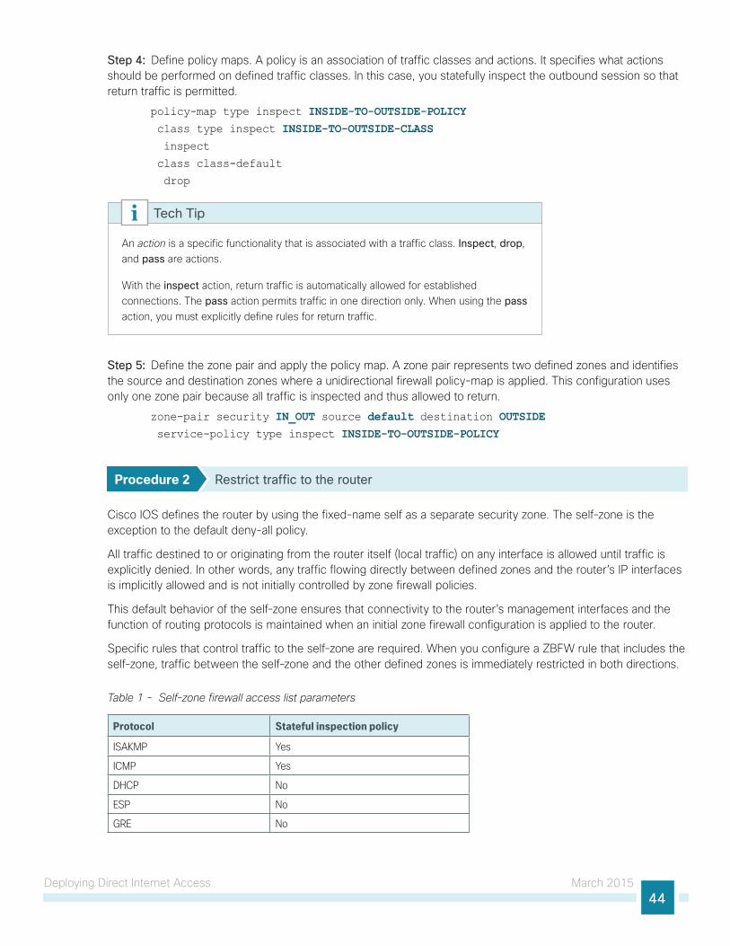
Deploying Direct Internet Access March 201544
Step 4: Define policy maps. A policy is an association of traffic classes and actions. It specifies what actions should be performed on defined traffic classes. In this case, you statefully inspect the outbound session so that return traffic is permitted.
policy-map type inspect INSIDE-TO-OUTSIDE-POLICY class type inspect INSIDE-TO-OUTSIDE-CLASS inspect
class class-default
drop
An action is a specific functionality that is associated with a traffic class. Inspect, drop, and pass are actions.
With the inspect action, return traffic is automatically allowed for established connections. The pass action permits traffic in one direction only. When using the pass action, you must explicitly define rules for return traffic.
Tech Tip
Step 5: Define the zone pair and apply the policy map. A zone pair represents two defined zones and identifies the source and destination zones where a unidirectional firewall policy-map is applied. This configuration uses only one zone pair because all traffic is inspected and thus allowed to return.
zone-pair security IN_OUT source default destination OUTSIDE service-policy type inspect INSIDE-TO-OUTSIDE-POLICY
Procedure 2 Restrict traffic to the router
Cisco IOS defines the router by using the fixed-name self as a separate security zone. The self-zone is the exception to the default deny-all policy.
All traffic destined to or originating from the router itself (local traffic) on any interface is allowed until traffic is explicitly denied. In other words, any traffic flowing directly between defined zones and the router’s IP interfaces is implicitly allowed and is not initially controlled by zone firewall policies.
This default behavior of the self-zone ensures that connectivity to the router’s management interfaces and the function of routing protocols is maintained when an initial zone firewall configuration is applied to the router.
Specific rules that control traffic to the self-zone are required. When you configure a ZBFW rule that includes the self-zone, traffic between the self-zone and the other defined zones is immediately restricted in both directions.
Table 1 - Self-zone firewall access list parameters
Protocol Stateful inspection policy
ISAKMP Yes
ICMP Yes
DHCP No
ESP No
GRE No
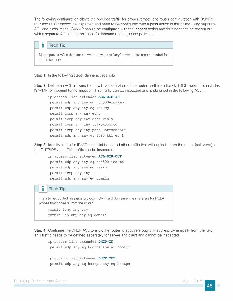
Deploying Direct Internet Access March 201545
The following configuration allows the required traffic for proper remote-site router configuration with DMVPN. ESP and DHCP cannot be inspected and need to be configured with a pass action in the policy, using separate ACL and class-maps. ISAKMP should be configured with the inspect action and thus needs to be broken out with a separate ACL and class-maps for inbound and outbound policies.
More specific ACLs than are shown here with the “any” keyword are recommended for added security.
Tech Tip
Step 1: In the following steps, define access lists.
Step 2: Define an ACL allowing traffic with a destination of the router itself from the OUTSIDE zone. This includes ISAKMP for inbound tunnel initiation. This traffic can be inspected and is identified in the following ACL.
ip access-list extended ACL-RTR-IN permit udp any any eq non500-isakmp
permit udp any any eq isakmp
permit icmp any any echo
permit icmp any any echo-reply
permit icmp any any ttl-exceeded
permit icmp any any port-unreachable
permit udp any any gt 1023 ttl eq 1
Step 3: Identify traffic for IPSEC tunnel initiation and other traffic that will originate from the router (self-zone) to the OUTSIDE zone. This traffic can be inspected.
ip access-list extended ACL-RTR-OUT permit udp any any eq non500-isakmp
permit udp any any eq isakmp
permit icmp any any
permit udp any any eq domain
The Internet control message protocol (ICMP) and domain entries here are for IPSLA probes that originate from the router.
permit icmp any any
permit udp any any eq domain
Tech Tip
Step 4: Configure the DHCP ACL to allow the router to acquire a public IP address dynamically from the ISP. This traffic needs to be defined separately for server and client and cannot be inspected.
ip access-list extended DHCP-IN permit udp any eq bootps any eq bootpc
ip access-list extended DHCP-OUT permit udp any eq bootpc any eq bootps
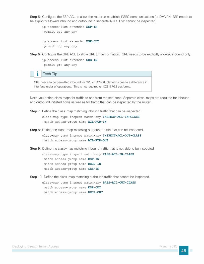
Deploying Direct Internet Access March 201546
Step 5: Configure the ESP ACL to allow the router to establish IPSEC communications for DMVPN. ESP needs to be explicitly allowed inbound and outbound in separate ACLs. ESP cannot be inspected.
ip access-list extended ESP-IN permit esp any any
ip access-list extended ESP-OUT permit esp any any
Step 6: Configure the GRE ACL to allow GRE tunnel formation. GRE needs to be explicitly allowed inbound only.
ip access-list extended GRE-IN permit gre any any
GRE needs to be permitted inbound for GRE on IOS-XE platforms due to a difference in interface order of operations. This is not required on IOS ISRG2 platforms.
Tech Tip
Next, you define class maps for traffic to and from the self-zone. Separate class-maps are required for inbound and outbound initiated flows as well as for traffic that can be inspected by the router.
Step 7: Define the class-map matching inbound traffic that can be inspected.
class-map type inspect match-any INSPECT-ACL-IN-CLASS match access-group name ACL-RTR-IN
Step 8: Define the class-map matching outbound traffic that can be inspected.
class-map type inspect match-any INSPECT-ACL-OUT-CLASS match access-group name ACL-RTR-OUT
Step 9: Define the class-map matching inbound traffic that is not able to be inspected.
class-map type inspect match-any PASS-ACL-IN-CLASS match access-group name ESP-IN match access-group name DHCP-IN match access-group name GRE-IN
Step 10: Define the class-map matching outbound traffic that cannot be inspected.
class-map type inspect match-any PASS-ACL-OUT-CLASS match access-group name ESP-OUT match access-group name DHCP-OUT
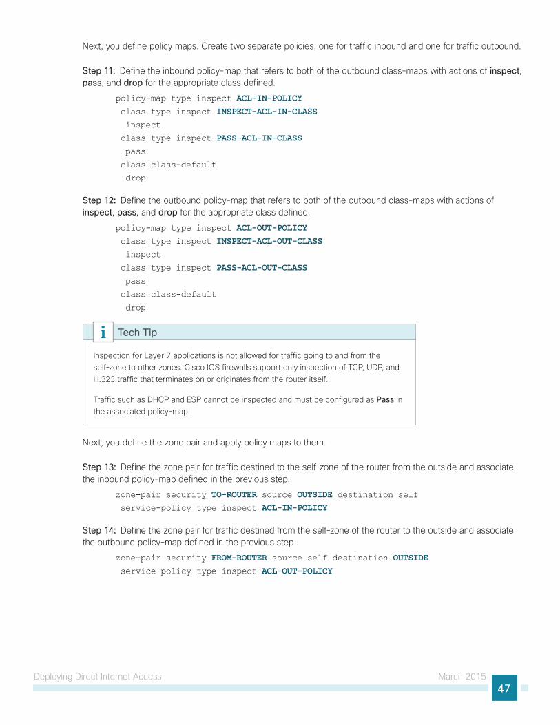
Deploying Direct Internet Access March 201547
Next, you define policy maps. Create two separate policies, one for traffic inbound and one for traffic outbound.
Step 11: Define the inbound policy-map that refers to both of the outbound class-maps with actions of inspect, pass, and drop for the appropriate class defined.
policy-map type inspect ACL-IN-POLICY class type inspect INSPECT-ACL-IN-CLASS inspect
class type inspect PASS-ACL-IN-CLASS pass
class class-default
drop
Step 12: Define the outbound policy-map that refers to both of the outbound class-maps with actions of inspect, pass, and drop for the appropriate class defined.
policy-map type inspect ACL-OUT-POLICY class type inspect INSPECT-ACL-OUT-CLASS inspect
class type inspect PASS-ACL-OUT-CLASS pass
class class-default
drop
Inspection for Layer 7 applications is not allowed for traffic going to and from the self-zone to other zones. Cisco IOS firewalls support only inspection of TCP, UDP, and H.323 traffic that terminates on or originates from the router itself.
Traffic such as DHCP and ESP cannot be inspected and must be configured as Pass in the associated policy-map.
Tech Tip
Next, you define the zone pair and apply policy maps to them.
Step 13: Define the zone pair for traffic destined to the self-zone of the router from the outside and associate the inbound policy-map defined in the previous step.
zone-pair security TO-ROUTER source OUTSIDE destination self service-policy type inspect ACL-IN-POLICY
Step 14: Define the zone pair for traffic destined from the self-zone of the router to the outside and associate the outbound policy-map defined in the previous step.
zone-pair security FROM-ROUTER source self destination OUTSIDE service-policy type inspect ACL-OUT-POLICY
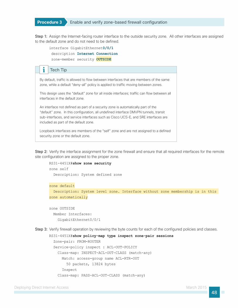
Deploying Direct Internet Access March 201548
Procedure 3 Enable and verify zone-based firewall configuration
Step 1: Assign the Internet-facing router interface to the outside security zone. All other interfaces are assigned to the default zone and do not need to be defined.
interface GigabitEthernet0/0/1 description Internet Connection zone-member security OUTSIDE
By default, traffic is allowed to flow between interfaces that are members of the same zone, while a default “deny-all” policy is applied to traffic moving between zones.
This design uses the “default” zone for all inside interfaces; traffic can flow between all interfaces in the default zone.
An interface not defined as part of a security zone is automatically part of the “default” zone. In this configuration, all undefined interface DMVPN tunnels, transit sub-interfaces, and service interfaces such as Cisco UCS-E, and SRE interfaces are included as part of the default zone.
Loopback interfaces are members of the “self” zone and are not assigned to a defined security zone or the default zone.
Tech Tip
Step 2: Verify the interface assignment for the zone firewall and ensure that all required interfaces for the remote site configuration are assigned to the proper zone.
RS31-4451X#show zone securityzone self
Description: System defined zone
zone default
Description: System level zone. Interface without zone membership is in this
zone automatically
zone OUTSIDE
Member Interfaces:
GigabitEthernet0/0/1
Step 3: Verify firewall operation by reviewing the byte counts for each of the configured policies and classes.
RS31-4451X#show policy-map type inspect zone-pair sessions Zone-pair: FROM-ROUTER
Service-policy inspect : ACL-OUT-POLICY
Class-map: INSPECT-ACL-OUT-CLASS (match-any)
Match: access-group name ACL-RTR-OUT
50 packets, 13824 bytes
Inspect
Class-map: PASS-ACL-OUT-CLASS (match-any)
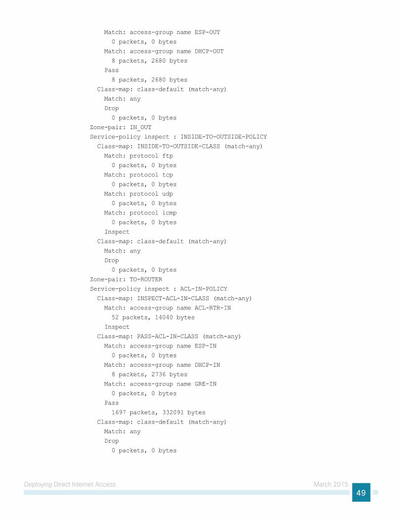
Deploying Direct Internet Access March 201549
Match: access-group name ESP-OUT
0 packets, 0 bytes
Match: access-group name DHCP-OUT
8 packets, 2680 bytes
Pass
8 packets, 2680 bytes
Class-map: class-default (match-any)
Match: any
Drop
0 packets, 0 bytes
Zone-pair: IN_OUT
Service-policy inspect : INSIDE-TO-OUTSIDE-POLICY
Class-map: INSIDE-TO-OUTSIDE-CLASS (match-any)
Match: protocol ftp
0 packets, 0 bytes
Match: protocol tcp
0 packets, 0 bytes
Match: protocol udp
0 packets, 0 bytes
Match: protocol icmp
0 packets, 0 bytes
Inspect
Class-map: class-default (match-any)
Match: any
Drop
0 packets, 0 bytes
Zone-pair: TO-ROUTER
Service-policy inspect : ACL-IN-POLICY
Class-map: INSPECT-ACL-IN-CLASS (match-any)
Match: access-group name ACL-RTR-IN
52 packets, 14040 bytes
Inspect
Class-map: PASS-ACL-IN-CLASS (match-any)
Match: access-group name ESP-IN
0 packets, 0 bytes
Match: access-group name DHCP-IN
8 packets, 2736 bytes
Match: access-group name GRE-IN
0 packets, 0 bytes
Pass
1697 packets, 332091 bytes
Class-map: class-default (match-any)
Match: any
Drop
0 packets, 0 bytes
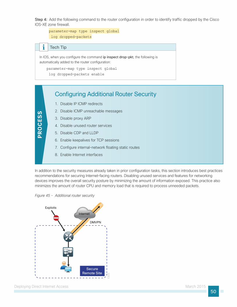
Deploying Direct Internet Access March 201550
Step 4: Add the following command to the router configuration in order to identify traffic dropped by the Cisco IOS-XE zone firewall.
parameter-map type inspect global
log dropped-packets
In IOS, when you configure the command ip inspect drop-pkt, the following is automatically added to the router configuration:
parameter-map type inspect global
log dropped-packets enable
Tech Tip
Configuring Additional Router Security
1. Disable IP ICMP redirects
2. Disable ICMP unreachable messages
3. Disable proxy ARP
4. Disable unused router services
5. Disable CDP and LLDP
6. Enable keepalives for TCP sessions
7. Configure internal-network floating static routes
8. Enable Internet interfaces
PR
OC
ESS
In addition to the security measures already taken in prior configuration tasks, this section introduces best practices recommendations for securing Internet-facing routers. Disabling unused services and features for networking devices improves the overall security posture by minimizing the amount of information exposed. This practice also minimizes the amount of router CPU and memory load that is required to process unneeded packets.
Figure 45 - Additional router security
13
05
Internet
SecureRemote Site
DMVPN
Exploits
Deploying Direct Internet Access March 201551
These are general security guidelines only. You may take additional measures to secure remote-site routers on a case-by-case basis. Take care to ensure that the disabling of certain features does not impact other functions of the network. For added security in hybrid IWAN designs, you can also apply these additional security configurations to MPLS provider interfaces.
Tech Tip
Procedure 1 Disable IP ICMP redirects
Routers use ICMP redirect messages to notify that a better route is available for a given destination. In this situation, the router forwards the packet and sends an ICMP redirect message back to the sender advising of an alternative and preferred route to the destination. In many implementations, there is no benefit in permitting this behavior. An attacker can generate traffic, forcing the router to respond with ICMP redirect messages, negatively impacting the CPU and performance of the router. You can prevent this by disabling ICMP redirect messages.
Step 1: Disable ICMP redirect messages on Internet-facing router interface.
interface GigabitEthernet0/0/1 description Internet Connection no ip redirects
Procedure 2 Disable ICMP unreachable messages
When filtering on router interfaces, routers send ICMP unreachable messages back to the source of blocked traffic. Generating these messages can increase CPU utilization on the router. By default, Cisco IOS ICMP unreachable messages are limited to one every 500 milliseconds. ICMP unreachable messages can be disabled on a per interface basis.
Step 1: Disable ICMP unreachable messages on Internet-facing router interface.
interface GigabitEthernet0/0/1 description Internet Connection no ip unreachables
Procedure 3 Disable proxy ARP
Proxy address resolution protocol (ARP) allows the router to respond to ARP request for hosts other than itself. Proxy ARP can help machines on a subnet reach remote subnets without configuring routing or a default gateway as defined in RFC 1027. Disadvantages to using proxy ARP:
• An attacker can impact available memory by sending a large number of ARP requests.
• A router is also susceptible to man-in-the-middle attacks where a host on the network could be used to spoof the MAC address of the router, resulting in unsuspecting hosts sending traffic to the attacker.
You can disable proxy ARP by using the interface configuration command.
Deploying Direct Internet Access March 201552
Step 1: Disable proxy ARP on Internet-facing router interface.
interface GigabitEthernet0/0/1 description Internet Connection no ip proxy-arp
Procedure 4 Disable unused router services
As a security best practice, you should disable all unnecessary services that could be used to launch denial of service (DoS) and other attacks. Many unused services that pose a security threat are disabled by default in current Cisco IOS versions.
Step 1: Disable maintenance operation protocol (MOP) on Internet-facing router interface.
interface GigabitEthernet0/0/1 description Internet Connection no mop enabled
Step 2: Disable Packet Assembler/Disassembler (PAD) service globally on the router.
no service pad
Step 3: Prevent the router from attempting to locate a configuration file via trivial file transfer protocol (TFTP) globally on the router.
no service config
Procedure 5 Disable CDP and LLDP
Attackers can use Cisco Discovery Protocol (CDP) and link layer discovery protocol (LLDP) for reconnaissance and network mapping. CDP is a network protocol that is used to discover other CDP-enabled devices. CDP is often used by network management systems (NMS) and for troubleshooting networking problems. LLDP is an IEEE protocol that is defined in 802.1AB and is very similar to CDP. You should disable CDP and LLDP on router interfaces that connect to untrusted networks.
Step 1: Disable CDP on Internet-facing router interface.
interface GigabitEthernet0/0/1 description Internet Connection no cdp enable
Step 2: Disable LLDP on Internet-facing router interface.
interface GigabitEthernet0/0/1 description Internet Connection no lldp transmit
no lldp receive
Deploying Direct Internet Access March 201553
Procedure 6 Enable keepalives for TCP sessions
This configuration enables TCP keepalives on inbound connections to the router and outbound connections from the router. This ensures that the device on the remote end of the connection is still accessible and half-open or orphaned connections are removed from the router.
Step 1: Enable the TCP keepalives service for inbound and outbound connections globally on the router.
service tcp-keepalives-in
service tcp-keepalives-out
Procedure 7 Configure internal-network floating static routes
In the event the DMVPN tunnel to the hub site fails, you will want to ensure traffic destined to internal networks does not follow the local Internet default route. It’s best to have the network fail closed to prevent possible security implications and unwanted routing behavior.
Configuring floating static routes to null zero with an AD of 254 ensures that all internal subnets route to null0 in the event of tunnel failure.
Step 1: Configure static route for internal network subnets.
ip route 10.0.0.0 255.0.0.0 null0 254
Configure the appropriate number of null 0 routes for internal network ranges, using summaries when possible for your specific network environment. Depending on the networking environment more specific statements may be required.
Tech Tip
Procedure 8 Enable Internet interfaces
Now that the security configurations are complete, you can enable the Internet-facing interfaces.
Step 1: Enable the Internet-facing router interface.
interface GigabitEthernet0/0/1 description Internet Connection no shutdown
Deploying Direct Internet Access March 201554
Configuring ISP Black-Hole Routing Detection
1. Configure ISP black-hole routing detectionP
RO
CES
S
In many cases you will need to ensure connectivity issues with your ISP does not cause black-hole routing conditions. Failure conditions can exist where the DHCP address and routes are not removed from the remote-site router when connectivity issues exist with the broadband service or local premise equipment. There may also be circumstances if certain services are unreachable within via the local ISP connection that you want to reroute to a secondary Internet service.
This configuration requires you to turn off Performance Routing (PfR) load-balancing on the Hub Master Controller. If PfR load-balancing is not turned off, the traffic will fail over to the central site Internet path, but it will not return to the local DIA interface after the failure condition is resolved.
Tech Tip
If central Internet fallback is required, configure one or more of the following options.
Procedure 1 Configure ISP black-hole routing detection
Option 1: DMVPN Tunnel State TrackingIn this solution, the DMVPN tunnel state is used to monitor the status of the ISP connection used as the primary path for local Internet traffic. In this example, a “down” state of the tunnel interface triggers the removal of the default route via an EEM script. If tunnel state is “up,” the route will remain.
With this method, a failure or maintenance at the central site can cause a failover event where the route is removed due to tunnel state change and the local Internet connection remains active at the remote site. In hybrid configurations, this can cause failover to Central Internet for multiple sites. It is recommended that you use the other options presented in this guide for hybrid DIA configurations.
Tech Tip
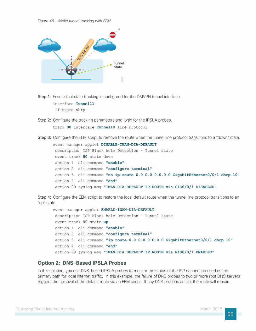
Deploying Direct Internet Access March 201555
Figure 46 - IWAN tunnel tracking with EEM
12
97
VPN T
unne
l
TunnelState
Step 1: Ensure that state tracking is configured for the DMVPN tunnel interface.
interface Tunnel11 if-state nhrp
Step 2: Configure the tracking parameters and logic for the IPSLA probes.
track 80 interface Tunnel10 line-protocol
Step 3: Configure the EEM script to remove the route when the tunnel line protocol transitions to a “down” state.
event manager applet DISABLE-IWAN-DIA-DEFAULT description ISP Black hole Detection - Tunnel state
event track 80 state down action 1 cli command "enable" action 2 cli command "configure terminal" action 3 cli command "no ip route 0.0.0.0 0.0.0.0 GigabitEthernet0/0/1 dhcp 10" action 4 cli command "end" action 99 syslog msg "IWAN DIA DEFAULT IP ROUTE via GIG0/0/1 DISABLED"
Step 4: Configure the EEM script to restore the local default route when the tunnel line protocol transitions to an “up” state.
event manager applet ENABLE-IWAN-DIA-DEFAULT description ISP Black hole Detection - Tunnel state
event track 80 state up action 1 cli command "enable" action 2 cli command "configure terminal" action 3 cli command "ip route 0.0.0.0 0.0.0.0 GigabitEthernet0/0/1 dhcp 10" action 4 cli command "end" action 99 syslog msg "IWAN DIA DEFAULT IP ROUTE via GIG0/0/1 ENABLED"
Option 2: DNS-Based IPSLA ProbesIn this solution, you use DNS-based IPSLA probes to monitor the status of the ISP connection used as the primary path for local Internet traffic. In this example, the failure of DNS probes to two or more root DNS servers triggers the removal of the default route via an EEM script. If any DNS probe is active, the route will remain.
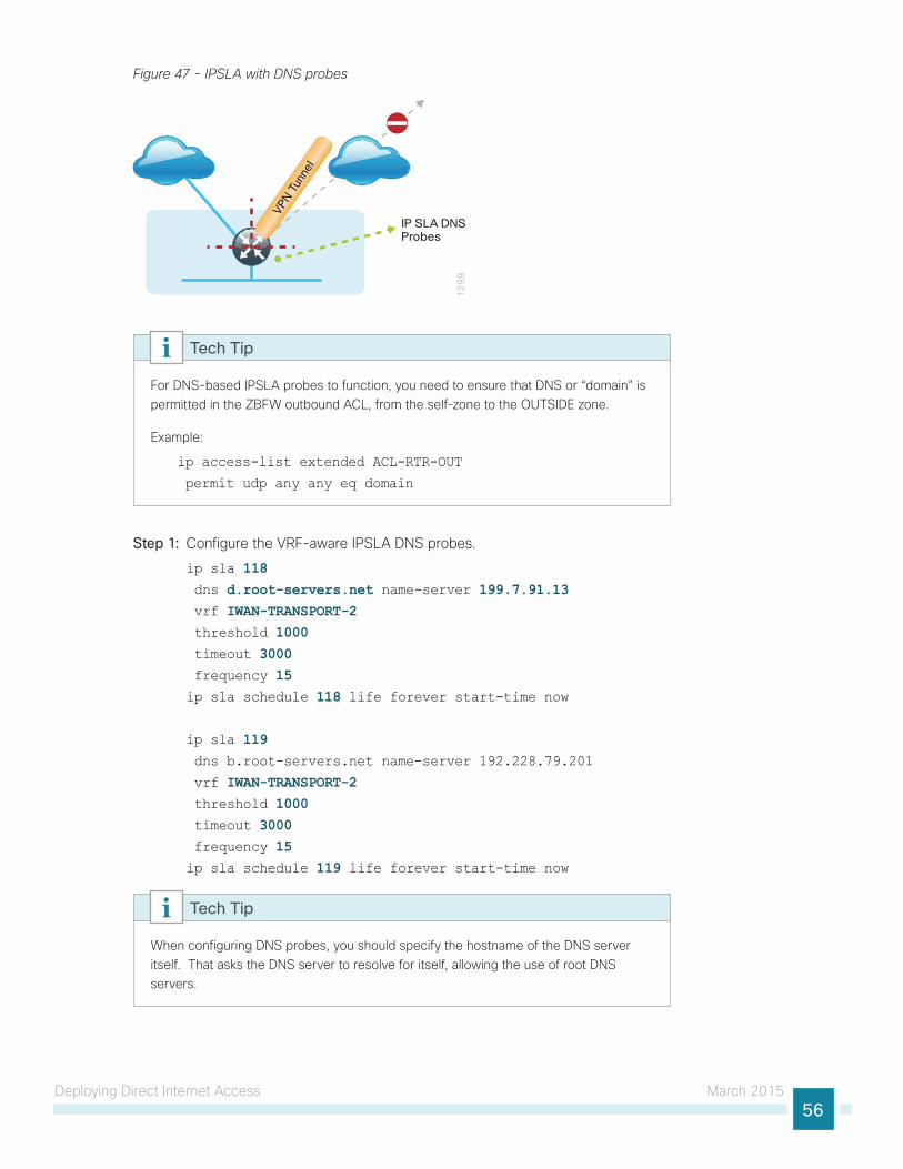
Deploying Direct Internet Access March 201556
Figure 47 - IPSLA with DNS probes
12
99
VPN T
unne
l
IP SLA DNSProbes
For DNS-based IPSLA probes to function, you need to ensure that DNS or “domain” is permitted in the ZBFW outbound ACL, from the self-zone to the OUTSIDE zone.
Example:
ip access-list extended ACL-RTR-OUT
permit udp any any eq domain
Tech Tip
Step 1: Configure the VRF-aware IPSLA DNS probes.
ip sla 118 dns d.root-servers.net name-server 199.7.91.13 vrf IWAN-TRANSPORT-2 threshold 1000 timeout 3000 frequency 15ip sla schedule 118 life forever start-time now
ip sla 119 dns b.root-servers.net name-server 192.228.79.201
vrf IWAN-TRANSPORT-2 threshold 1000 timeout 3000 frequency 15ip sla schedule 119 life forever start-time now
When configuring DNS probes, you should specify the hostname of the DNS server itself. That asks the DNS server to resolve for itself, allowing the use of root DNS servers.
Tech Tip
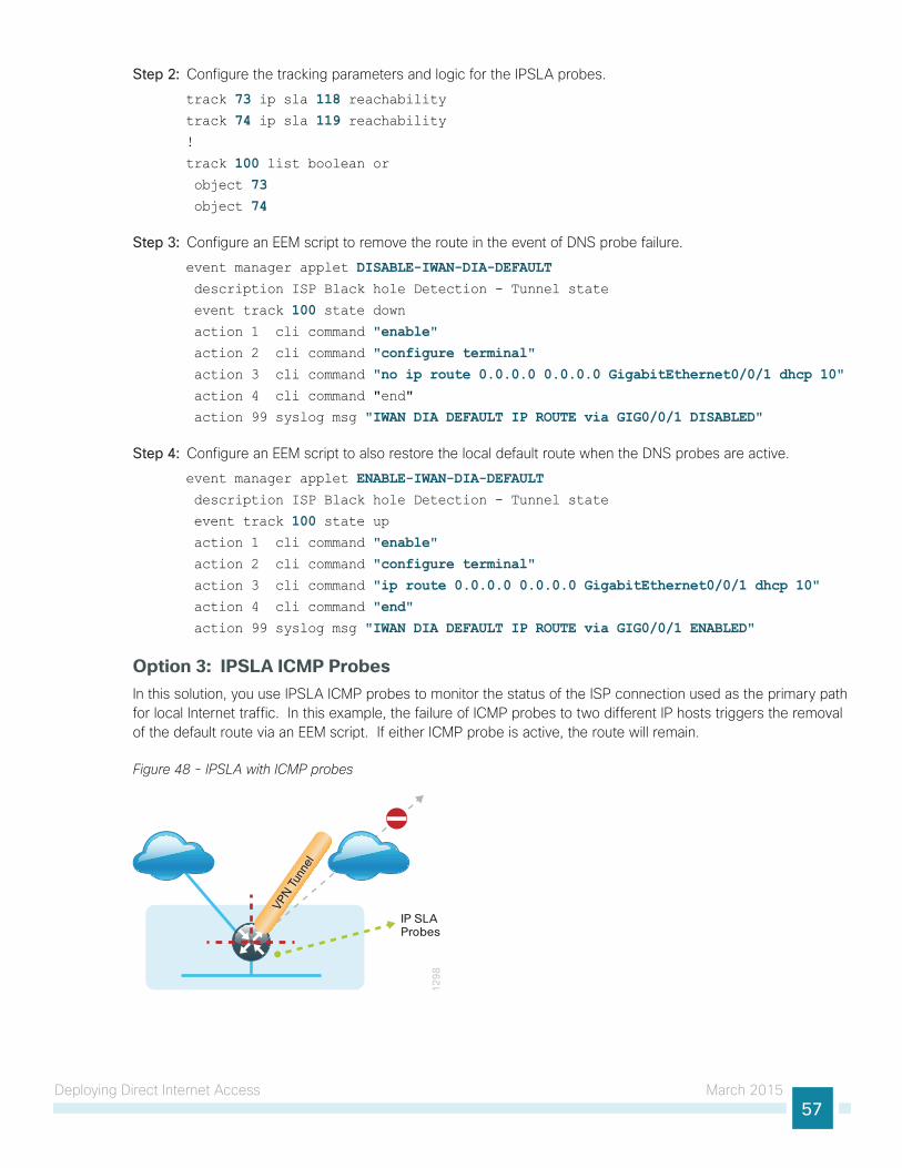
Deploying Direct Internet Access March 201557
Step 2: Configure the tracking parameters and logic for the IPSLA probes.
track 73 ip sla 118 reachabilitytrack 74 ip sla 119 reachability!
track 100 list boolean or object 73 object 74
Step 3: Configure an EEM script to remove the route in the event of DNS probe failure.
event manager applet DISABLE-IWAN-DIA-DEFAULT description ISP Black hole Detection - Tunnel state
event track 100 state down action 1 cli command "enable" action 2 cli command "configure terminal" action 3 cli command "no ip route 0.0.0.0 0.0.0.0 GigabitEthernet0/0/1 dhcp 10" action 4 cli command "end"
action 99 syslog msg "IWAN DIA DEFAULT IP ROUTE via GIG0/0/1 DISABLED"
Step 4: Configure an EEM script to also restore the local default route when the DNS probes are active.
event manager applet ENABLE-IWAN-DIA-DEFAULT description ISP Black hole Detection - Tunnel state
event track 100 state up action 1 cli command "enable" action 2 cli command "configure terminal" action 3 cli command "ip route 0.0.0.0 0.0.0.0 GigabitEthernet0/0/1 dhcp 10" action 4 cli command "end" action 99 syslog msg "IWAN DIA DEFAULT IP ROUTE via GIG0/0/1 ENABLED"
Option 3: IPSLA ICMP ProbesIn this solution, you use IPSLA ICMP probes to monitor the status of the ISP connection used as the primary path for local Internet traffic. In this example, the failure of ICMP probes to two different IP hosts triggers the removal of the default route via an EEM script. If either ICMP probe is active, the route will remain.
Figure 48 - IPSLA with ICMP probes
12
98
VPN T
unne
l
IP SLAProbes
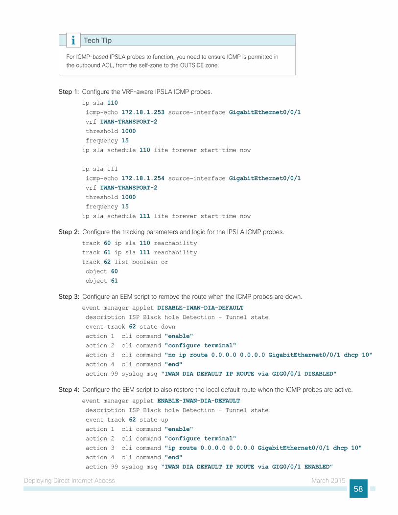
Deploying Direct Internet Access March 201558
For ICMP-based IPSLA probes to function, you need to ensure ICMP is permitted in the outbound ACL, from the self-zone to the OUTSIDE zone.
Tech Tip
Step 1: Configure the VRF-aware IPSLA ICMP probes.
ip sla 110 icmp-echo 172.18.1.253 source-interface GigabitEthernet0/0/1 vrf IWAN-TRANSPORT-2 threshold 1000 frequency 15ip sla schedule 110 life forever start-time now
ip sla 111
icmp-echo 172.18.1.254 source-interface GigabitEthernet0/0/1 vrf IWAN-TRANSPORT-2 threshold 1000 frequency 15ip sla schedule 111 life forever start-time now
Step 2: Configure the tracking parameters and logic for the IPSLA ICMP probes.
track 60 ip sla 110 reachabilitytrack 61 ip sla 111 reachabilitytrack 62 list boolean or object 60 object 61
Step 3: Configure an EEM script to remove the route when the ICMP probes are down.
event manager applet DISABLE-IWAN-DIA-DEFAULT description ISP Black hole Detection - Tunnel state
event track 62 state down action 1 cli command "enable" action 2 cli command "configure terminal" action 3 cli command "no ip route 0.0.0.0 0.0.0.0 GigabitEthernet0/0/1 dhcp 10" action 4 cli command "end" action 99 syslog msg "IWAN DIA DEFAULT IP ROUTE via GIG0/0/1 DISABLED"
Step 4: Configure the EEM script to also restore the local default route when the ICMP probes are active.
event manager applet ENABLE-IWAN-DIA-DEFAULT description ISP Black hole Detection - Tunnel state
event track 62 state up action 1 cli command "enable" action 2 cli command "configure terminal" action 3 cli command "ip route 0.0.0.0 0.0.0.0 GigabitEthernet0/0/1 dhcp 10" action 4 cli command "end" action 99 syslog msg “IWAN DIA DEFAULT IP ROUTE via GIG0/0/1 ENABLED”
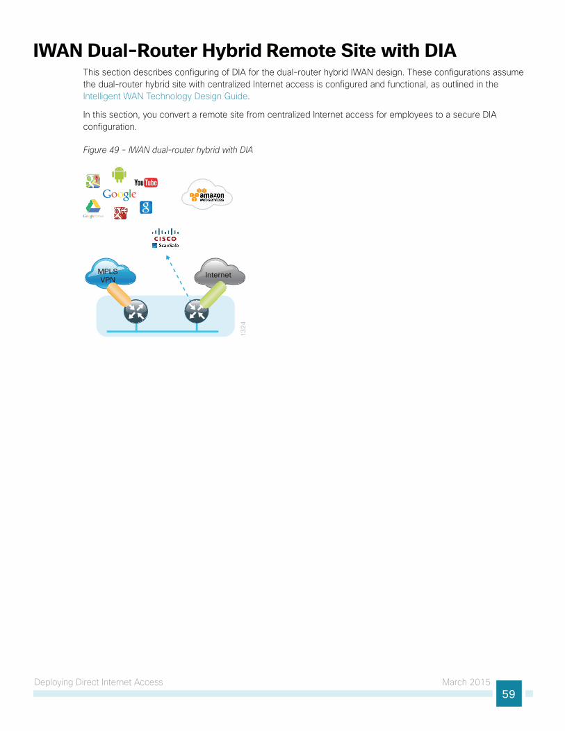
Deploying Direct Internet Access March 201559
IWAN Dual-Router Hybrid Remote Site with DIAThis section describes configuring of DIA for the dual-router hybrid IWAN design. These configurations assume the dual-router hybrid site with centralized Internet access is configured and functional, as outlined in the Intelligent WAN Technology Design Guide.
In this section, you convert a remote site from centralized Internet access for employees to a secure DIA configuration.
Figure 49 - IWAN dual-router hybrid with DIA
13
24
InternetMPLSVPN

Deploying Direct Internet Access March 201560
Configuring DIA Routing
1. Configure Internet interface
2. Filter EIGRP learned central default route
3. Configure local default routing for outbound local Internet traffic
4. Configure local policy routing for return Internet traffic
5. Filter default route outbound to WAN
6. Redistribute DHCP default route into EIGRP
PR
OC
ESS
In the following procedures, you enable DIA routing, NAT and zone-based firewall configurations for the dual-router hybrid IWAN design. In this configuration, you route local Internet traffic by using split-tunneling outside the DMVPN tunnel on the secondary router. All configurations are specific to this design model.
Procedure 1 Configure Internet interface
For security, disable the ISP interface before configuring DIA. You will not restore this interface until you complete all of the configurations in this section.
If you are remotely connected to the remote-site router via SSH, you will be disconnected from the router console. Shutting down the Internet interface will drop the existing DMVPN tunnel.
Tech Tip
Step 1: Verify that the Internet-facing interface is disabled.
interface GigabitEthernet0/0/0 shutdown
Procedure 2 Filter EIGRP learned central default route
With DIA routing, the default route is locally configured for the global routing table. It is important to filter the default route originating over the Internet-facing DMVPN tunnel from the central site. Failover to the central site is optional over the MPLS-based DMVPN tunnel. In the single-router hybrid design with DIA, all Internet traffic is routed directly to the local ISP interface; it is not feasible to failover to central Internet by using an Internet-based DMVPN tunnel.
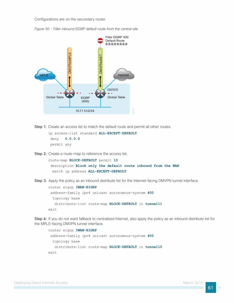
Deploying Direct Internet Access March 201561
Configurations are on the secondary router.
Figure 50 - Filter inbound EIGRP default route from the central site
Global Table
12
75
Internet
G0/0/0
MPLS
DM
VP
No
INE
T
10.7.112.0/24
DM
VP
No
MP
LS
EIGRP(400)
Filter EIGRP 400Default Route0.0.0.0 0.0.0.0
Global Table
Step 1: Create an access list to match the default route and permit all other routes.
ip access-list standard ALL-EXCEPT-DEFAULT deny 0.0.0.0 permit any
Step 2: Create a route-map to reference the access list.
route-map BLOCK-DEFAULT permit 10 description Block only the default route inbound from the WAN match ip address ALL-EXCEPT-DEFAULT
Step 3: Apply the policy as an inbound distribute list for the Internet-facing DMVPN tunnel interface.
router eigrp IWAN-EIGRP address-family ipv4 unicast autonomous-system 400 topology base
distribute-list route-map BLOCK-DEFAULT in tunnel11exit
Step 4: If you do not want fallback to centralized Internet, also apply the policy as an inbound distribute list for the MPLS-facing DMVPN tunnel interface.
router eigrp IWAN-EIGRP address-family ipv4 unicast autonomous-system 400 topology base
distribute-list route-map BLOCK-DEFAULT in tunnel10exit
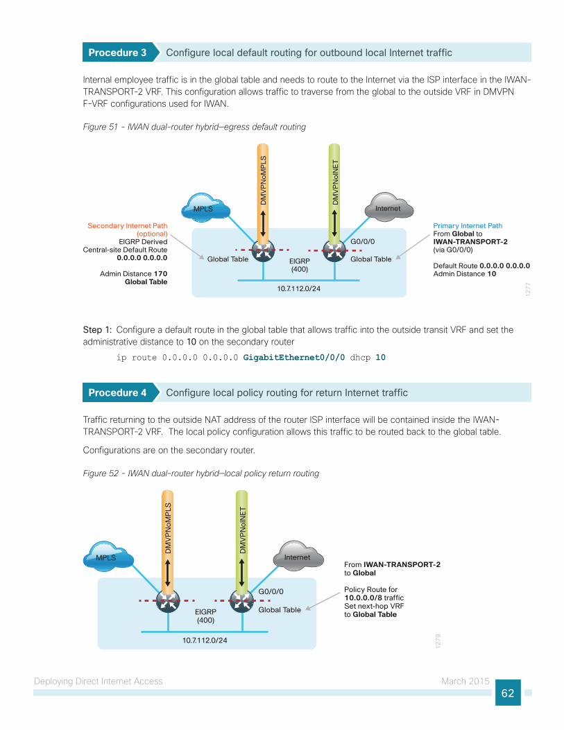
Deploying Direct Internet Access March 201562
Procedure 3 Configure local default routing for outbound local Internet traffic
Internal employee traffic is in the global table and needs to route to the Internet via the ISP interface in the IWAN-TRANSPORT-2 VRF. This configuration allows traffic to traverse from the global to the outside VRF in DMVPN F-VRF configurations used for IWAN.
Figure 51 - IWAN dual-router hybrid—egress default routing
12
77
InternetMPLS
DM
VP
No
INE
T
DM
VP
No
MP
LSEIGRP(400)
Global Table
G0/0/0
Global Table
Secondary Internet Path(optional)
EIGRP DerivedCentral-site Default Route
0.0.0.0 0.0.0.0
Admin Distance 170Global Table
Primary Internet PathFrom Global toIWAN-TRANSPORT-2(via G0/0/0)
Default Route 0.0.0.0 0.0.0.0Admin Distance 10
10.7.112.0/24
Step 1: Configure a default route in the global table that allows traffic into the outside transit VRF and set the administrative distance to 10 on the secondary router
ip route 0.0.0.0 0.0.0.0 GigabitEthernet0/0/0 dhcp 10
Procedure 4 Configure local policy routing for return Internet traffic
Traffic returning to the outside NAT address of the router ISP interface will be contained inside the IWAN-TRANSPORT-2 VRF. The local policy configuration allows this traffic to be routed back to the global table.
Configurations are on the secondary router.
Figure 52 - IWAN dual-router hybrid—local policy return routing
12
79
InternetMPLS
DM
VP
No
INE
T
DM
VP
No
MP
LS
EIGRP(400)
G0/0/0
Global Table
From IWAN-TRANSPORT-2 to Global
Policy Route for 10.0.0.0/8 traffic Set next-hop VRF to Global Table
10.7.112.0/24
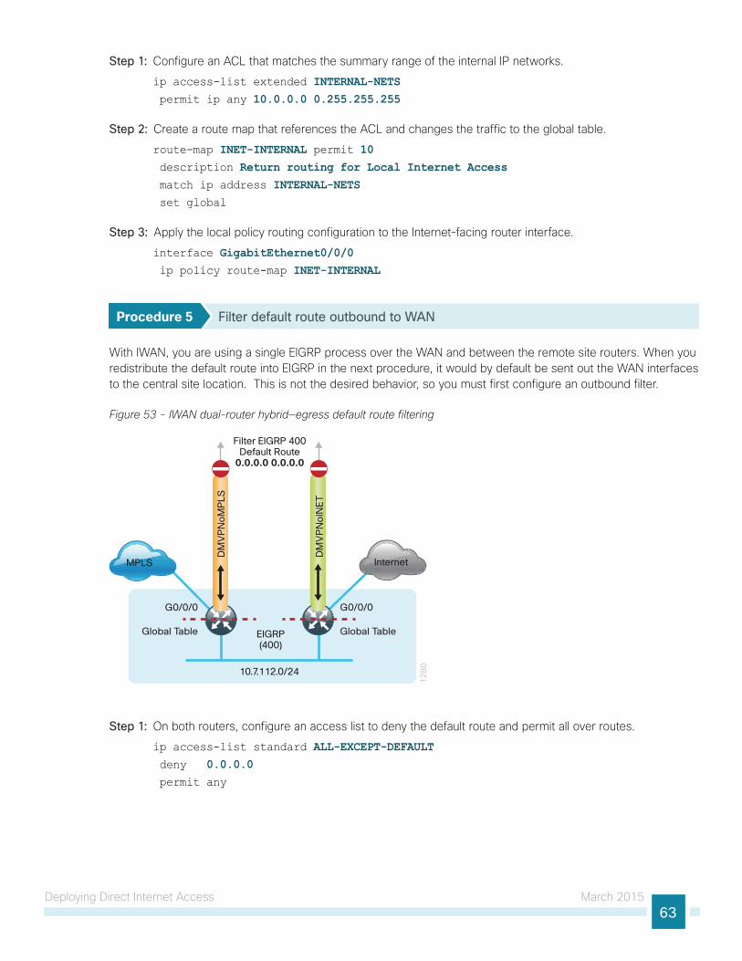
Deploying Direct Internet Access March 201563
Step 1: Configure an ACL that matches the summary range of the internal IP networks.
ip access-list extended INTERNAL-NETS permit ip any 10.0.0.0 0.255.255.255
Step 2: Create a route map that references the ACL and changes the traffic to the global table.
route-map INET-INTERNAL permit 10 description Return routing for Local Internet Access match ip address INTERNAL-NETS set global
Step 3: Apply the local policy routing configuration to the Internet-facing router interface.
interface GigabitEthernet0/0/0 ip policy route-map INET-INTERNAL
Procedure 5 Filter default route outbound to WAN
With IWAN, you are using a single EIGRP process over the WAN and between the remote site routers. When you redistribute the default route into EIGRP in the next procedure, it would by default be sent out the WAN interfaces to the central site location. This is not the desired behavior, so you must first configure an outbound filter.
Figure 53 - IWAN dual-router hybrid—egress default route filtering1
28
0
InternetMPLS
DM
VP
No
INE
T
DM
VP
No
MP
LS
EIGRP(400)
Global Table
G0/0/0
Global Table
10.7.112.0/24
Filter EIGRP 400Default Route
0.0.0.0 0.0.0.0
G0/0/0
Step 1: On both routers, configure an access list to deny the default route and permit all over routes.
ip access-list standard ALL-EXCEPT-DEFAULT deny 0.0.0.0 permit any
Deploying Direct Internet Access March 201564
Step 2: On both routers, add an instance after the existing route map named “ROUTE-LIST” and reference the access list that denies the default route and permits all other routes. There should be an instance of this route map from the IWAN foundation configuration. This statement should go between the existing statements.
route-map ROUTE-LIST deny 20 description Block Local Internet Default route out to the WAN match ip address DEFAULT-ONLY
Step 3: On the primary router, ensure that the route map is applied as an outbound distribution list on the DMVPN tunnel interface. Apply this as part of the foundational configuration for dual-router egress filtering.
router eigrp IWAN-EIGRP !
address-family ipv4 unicast autonomous-system 400 topology base
distribute-list route-map ROUTE-LIST out Tunnel10 exit-af-topology
exit-address-family
Step 4: On the secondary router, ensure that the route map is applied as an outbound distribution list on the DMVPN tunnel interface. Apply this as part of the foundational configuration for dual-router egress filtering.
router eigrp IWAN-EIGRP !
address-family ipv4 unicast autonomous-system 400 topology base
distribute-list route-map ROUTE-LIST out Tunnel11 exit-af-topology
exit-address-family
Procedure 6 Redistribute DHCP default route into EIGRP
For dual-router configurations, you need to redistribute the statically configured default route into EIGRP AS400 for reachability on both WAN routers.
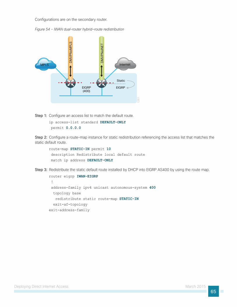
Deploying Direct Internet Access March 201565
Configurations are on the secondary router.
Figure 54 - IWAN dual-router hybrid—route redistribution
12
81
InternetMPLS
DM
VP
No
INE
T
DM
VP
No
MP
LS
EIGRP(400)
Static
EIGRP
Step 1: Configure an access list to match the default route.
ip access-list standard DEFAULT-ONLY permit 0.0.0.0
Step 2: Configure a route-map instance for static redistribution referencing the access list that matches the static default route.
route-map STATIC-IN permit 10 description Redistribute local default route
match ip address DEFAULT-ONLY
Step 3: Redistribute the static default route installed by DHCP into EIGRP AS400 by using the route map.
router eigrp IWAN-EIGRP !
address-family ipv4 unicast autonomous-system 400 topology base
redistribute static route-map STATIC-IN exit-af-topology
exit-address-family
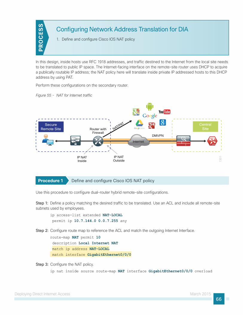
Deploying Direct Internet Access March 201566
Configuring Network Address Translation for DIA
1. Define and configure Cisco IOS NAT policyP
RO
CES
S
In this design, inside hosts use RFC 1918 addresses, and traffic destined to the Internet from the local site needs to be translated to public IP space. The Internet-facing interface on the remote-site router uses DHCP to acquire a publically routable IP address; the NAT policy here will translate inside private IP addressed hosts to this DHCP address by using PAT.
Perform these configurations on the secondary router.
Figure 55 - NAT for Internet traffic
13
01
Internet
DMVPN
IP NATInside
Router withFirewall
IP NATOutside
CentralSite
SecureRemote Site NAT/PAT
Procedure 1 Define and configure Cisco IOS NAT policy
Use this procedure to configure dual-router hybrid remote-site configurations.
Step 1: Define a policy matching the desired traffic to be translated. Use an ACL and include all remote-site subnets used by employees.
ip access-list extended NAT-LOCAL permit ip 10.7.144.0 0.0.7.255 any
Step 2: Configure route map to reference the ACL and match the outgoing Internet Interface.
route-map NAT permit 10 description Local Internet NAT match ip address NAT-LOCAL match interface GigabitEthernet0/0/0
Step 3: Configure the NAT policy.
ip nat inside source route-map NAT interface GigabitEthernet0/0/0 overload
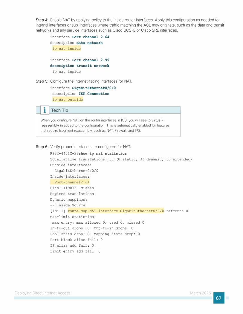
Deploying Direct Internet Access March 201567
Step 4: Enable NAT by applying policy to the inside router interfaces. Apply this configuration as needed to internal interfaces or sub-interfaces where traffic matching the ACL may originate, such as the data and transit networks and any service interfaces such as Cisco UCS-E or Cisco SRE interfaces.
interface Port-channel 2.64description data network ip nat inside
interface Port-channel 2.99description transit network ip nat inside
Step 5: Configure the Internet-facing interfaces for NAT.
interface GigabitEthernet0/0/0 description ISP Connection ip nat outside
When you configure NAT on the router interfaces in IOS, you will see ip virtual-reassembly in added to the configuration. This is automatically enabled for features that require fragment reassembly, such as NAT, Firewall, and IPS.
Tech Tip
Step 6: Verify proper interfaces are configured for NAT.
RS32-4451X-2#show ip nat statistics Total active translations: 33 (0 static, 33 dynamic; 33 extended)
Outside interfaces:
GigabitEthernet0/0/0
Inside interfaces:
Port-channel2.64
Hits: 119073 Misses:
Expired translations:
Dynamic mappings:
-- Inside Source
[Id: 1] route-map NAT interface GigabitEthernet0/0/0 refcount 0
nat-limit statistics:
max entry: max allowed 0, used 0, missed 0
In-to-out drops: 0 Out-to-in drops: 0
Pool stats drop: 0 Mapping stats drop: 0
Port block alloc fail: 0
IP alias add fail: 0
Limit entry add fail: 0
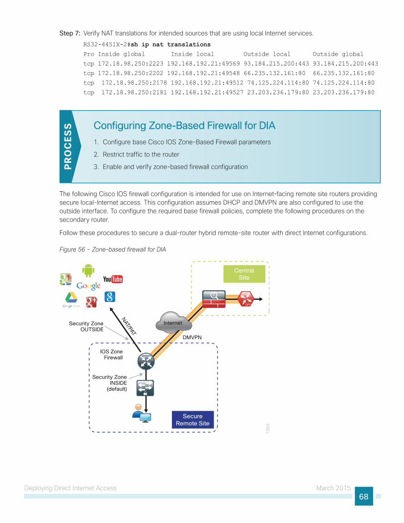
Deploying Direct Internet Access March 201568
Step 7: Verify NAT translations for intended sources that are using local Internet services.
RS32-4451X-2#sh ip nat translations Pro Inside global Inside local Outside local Outside global
tcp 172.18.98.250:2223 192.168.192.21:49569 93.184.215.200:443 93.184.215.200:443
tcp 172.18.98.250:2202 192.168.192.21:49548 66.235.132.161:80 66.235.132.161:80
tcp 172.18.98.250:2178 192.168.192.21:49512 74.125.224.114:80 74.125.224.114:80
tcp 172.18.98.250:2181 192.168.192.21:49527 23.203.236.179:80 23.203.236.179:80
Configuring Zone-Based Firewall for DIA
1. Configure base Cisco IOS Zone-Based Firewall parameters
2. Restrict traffic to the router
3. Enable and verify zone-based firewall configurationPR
OC
ESS
The following Cisco IOS firewall configuration is intended for use on Internet-facing remote site routers providing secure local-Internet access. This configuration assumes DHCP and DMVPN are also configured to use the outside interface. To configure the required base firewall policies, complete the following procedures on the secondary router.
Follow these procedures to secure a dual-router hybrid remote-site router with direct Internet configurations.
Figure 56 - Zone-based firewall for DIA
13
04
Internet
CentralSite
SecureRemote Site
IOS ZoneFirewall
DMVPN
Security ZoneOUTSIDE
Security ZoneINSIDE
(default)
NAT/PAT
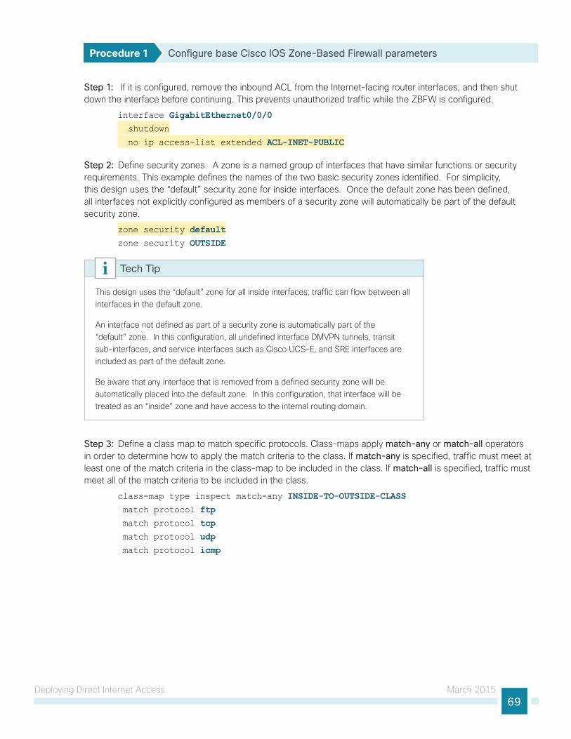
Deploying Direct Internet Access March 201569
Procedure 1 Configure base Cisco IOS Zone-Based Firewall parameters
Step 1: If it is configured, remove the inbound ACL from the Internet-facing router interfaces, and then shut down the interface before continuing. This prevents unauthorized traffic while the ZBFW is configured.
interface GigabitEthernet0/0/0 shutdown
no ip access-list extended ACL-INET-PUBLIC
Step 2: Define security zones. A zone is a named group of interfaces that have similar functions or security requirements. This example defines the names of the two basic security zones identified. For simplicity, this design uses the “default” security zone for inside interfaces. Once the default zone has been defined, all interfaces not explicitly configured as members of a security zone will automatically be part of the default security zone.
zone security defaultzone security OUTSIDE
This design uses the “default” zone for all inside interfaces; traffic can flow between all interfaces in the default zone.
An interface not defined as part of a security zone is automatically part of the “default” zone. In this configuration, all undefined interface DMVPN tunnels, transit sub-interfaces, and service interfaces such as Cisco UCS-E, and SRE interfaces are included as part of the default zone.
Be aware that any interface that is removed from a defined security zone will be automatically placed into the default zone. In this configuration, that interface will be treated as an “inside” zone and have access to the internal routing domain.
Tech Tip
Step 3: Define a class map to match specific protocols. Class-maps apply match-any or match-all operators in order to determine how to apply the match criteria to the class. If match-any is specified, traffic must meet at least one of the match criteria in the class-map to be included in the class. If match-all is specified, traffic must meet all of the match criteria to be included in the class.
class-map type inspect match-any INSIDE-TO-OUTSIDE-CLASS match protocol ftp match protocol tcp match protocol udp match protocol icmp
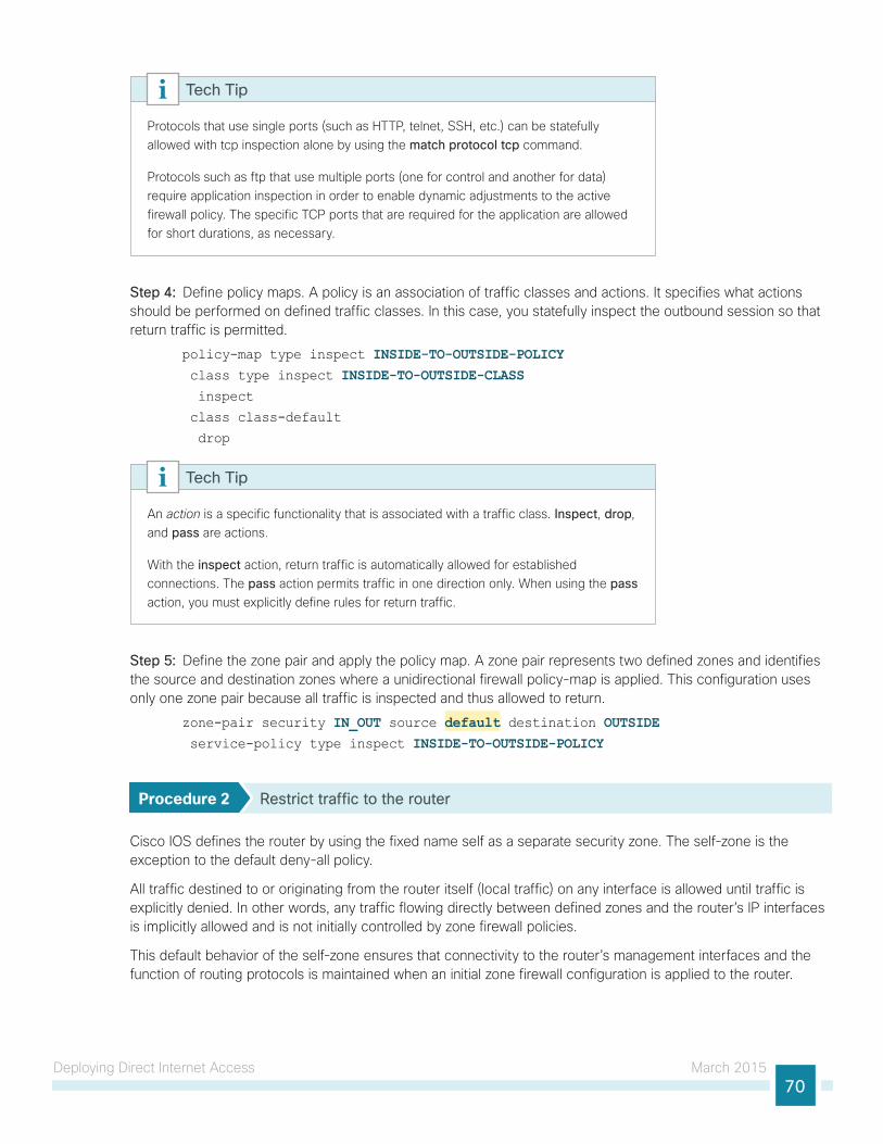
Deploying Direct Internet Access March 201570
Protocols that use single ports (such as HTTP, telnet, SSH, etc.) can be statefully allowed with tcp inspection alone by using the match protocol tcp command.
Protocols such as ftp that use multiple ports (one for control and another for data) require application inspection in order to enable dynamic adjustments to the active firewall policy. The specific TCP ports that are required for the application are allowed for short durations, as necessary.
Tech Tip
Step 4: Define policy maps. A policy is an association of traffic classes and actions. It specifies what actions should be performed on defined traffic classes. In this case, you statefully inspect the outbound session so that return traffic is permitted.
policy-map type inspect INSIDE-TO-OUTSIDE-POLICY class type inspect INSIDE-TO-OUTSIDE-CLASS inspect
class class-default
drop
An action is a specific functionality that is associated with a traffic class. Inspect, drop, and pass are actions.
With the inspect action, return traffic is automatically allowed for established connections. The pass action permits traffic in one direction only. When using the pass action, you must explicitly define rules for return traffic.
Tech Tip
Step 5: Define the zone pair and apply the policy map. A zone pair represents two defined zones and identifies the source and destination zones where a unidirectional firewall policy-map is applied. This configuration uses only one zone pair because all traffic is inspected and thus allowed to return.
zone-pair security IN_OUT source default destination OUTSIDE service-policy type inspect INSIDE-TO-OUTSIDE-POLICY
Procedure 2 Restrict traffic to the router
Cisco IOS defines the router by using the fixed name self as a separate security zone. The self-zone is the exception to the default deny-all policy.
All traffic destined to or originating from the router itself (local traffic) on any interface is allowed until traffic is explicitly denied. In other words, any traffic flowing directly between defined zones and the router’s IP interfaces is implicitly allowed and is not initially controlled by zone firewall policies.
This default behavior of the self-zone ensures that connectivity to the router’s management interfaces and the function of routing protocols is maintained when an initial zone firewall configuration is applied to the router.

Deploying Direct Internet Access March 201571
Specific rules that control traffic to the self-zone are required. When you configure a ZBFW rule that includes the self-zone, traffic between the self-zone and the other defined zones is immediately restricted in both directions.
Table 2 - Self-zone firewall access list parameters
Protocol Stateful inspection policy
ISAKMP Yes
ICMP Yes
DHCP No
ESP No
GRE No
The following configuration allows the required traffic for proper remote-site router configuration with DMVPN. ESP and DHCP cannot be inspected and need to be configured with a pass action in the policy, using separate ACL and class-maps. ISAKMP should be configured with the inspect action and thus needs to be broken out with a separate ACL and class-maps for inbound and outbound policies.
More specific ACLs than are shown here with the “any” keyword are recommended for added security.
Tech Tip
Step 1: In the following steps, define access lists.
Step 2: Define an ACL allowing traffic with a destination of the router itself from the OUTSIDE zone. This includes ISAKMP for inbound tunnel initiation. This traffic can be inspected and is identified in the following ACL.
ip access-list extended ACL-RTR-IN permit udp any any eq non500-isakmp
permit udp any any eq isakmp
permit icmp any any echo
permit icmp any any echo-reply
permit icmp any any ttl-exceeded
permit icmp any any port-unreachable
permit udp any any gt 1023 ttl eq 1
Step 3: Identify traffic for IPSEC tunnel initiation and other traffic that will originate from the router (self-zone) to the OUTSIDE zone. This traffic can be inspected.
ip access-list extended ACL-RTR-OUT permit udp any any eq non500-isakmp
permit udp any any eq isakmp
permit icmp any any
permit udp any any eq domain
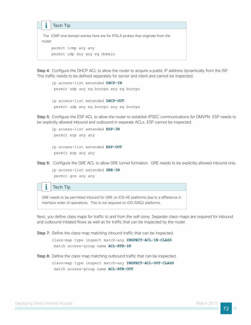
Deploying Direct Internet Access March 201572
The ICMP and domain entries here are for IPSLA probes that originate from the router.
permit icmp any any
permit udp any any eq domain
Tech Tip
Step 4: Configure the DHCP ACL to allow the router to acquire a public IP address dynamically from the ISP. This traffic needs to be defined separately for server and client and cannot be inspected.
ip access-list extended DHCP-IN permit udp any eq bootps any eq bootpc
ip access-list extended DHCP-OUT permit udp any eq bootpc any eq bootps
Step 5: Configure the ESP ACL to allow the router to establish IPSEC communications for DMVPN. ESP needs to be explicitly allowed inbound and outbound in separate ACLs. ESP cannot be inspected.
ip access-list extended ESP-IN permit esp any any
ip access-list extended ESP-OUT permit esp any any
Step 6: Configure the GRE ACL to allow GRE tunnel formation. GRE needs to be explicitly allowed inbound only.
ip access-list extended GRE-IN permit gre any any
GRE needs to be permitted inbound for GRE on IOS-XE platforms due to a difference in interface order of operations. This is not required on IOS ISRG2 platforms.
Tech Tip
Next, you define class maps for traffic to and from the self-zone. Separate class-maps are required for inbound and outbound initiated flows as well as for traffic that can be inspected by the router.
Step 7: Define the class-map matching inbound traffic that can be inspected.
class-map type inspect match-any INSPECT-ACL-IN-CLASS match access-group name ACL-RTR-IN
Step 8: Define the class-map matching outbound traffic that can be inspected.
class-map type inspect match-any INSPECT-ACL-OUT-CLASS match access-group name ACL-RTR-OUT

Deploying Direct Internet Access March 201573
Step 9: Define the class-map matching inbound traffic that is not able to be inspected.
class-map type inspect match-any PASS-ACL-IN-CLASS match access-group name ESP-IN match access-group name DHCP-IN match access-group name GRE-IN
Step 10: Define the class-map matching outbound traffic that cannot be inspected.
class-map type inspect match-any PASS-ACL-OUT-CLASS match access-group name ESP-OUT match access-group name DHCP-OUT
Next, you define policy maps. Create two separate policies, one for traffic inbound and one for traffic outbound.
Step 11: Define the inbound policy-map that refers to both of the outbound class-maps with actions of inspect, pass, and drop for the appropriate class defined.
policy-map type inspect ACL-IN-POLICY class type inspect INSPECT-ACL-IN-CLASS inspect
class type inspect PASS-ACL-IN-CLASS pass
class class-default
drop
Step 12: Define the outbound policy-map that refers to both of the outbound class-maps with actions of inspect, pass, and drop for the appropriate class defined.
policy-map type inspect ACL-OUT-POLICY class type inspect INSPECT-ACL-OUT-CLASS inspect
class type inspect PASS-ACL-OUT-CLASS pass
class class-default
drop
Inspection for Layer 7 applications is not allowed for traffic going to and from the self-zone to other zones. Cisco IOS firewalls support only inspection of TCP, UDP, and H.323 traffic that terminates on or originates from the router itself.
Traffic such as DHCP and ESP cannot be inspected and must be configured as Pass in the associated policy-map.
Tech Tip
Next, you define the zone pair and apply policy maps to them.
Step 13: Define the zone pair for traffic destined to the self-zone of the router from the outside and associate the inbound policy-map defined in the previous step.
zone-pair security TO-ROUTER source OUTSIDE destination self service-policy type inspect ACL-IN-POLICY
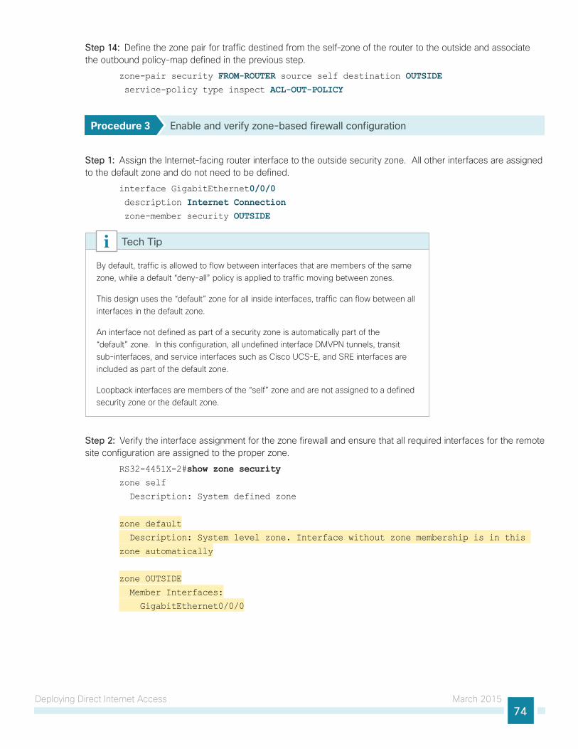
Deploying Direct Internet Access March 201574
Step 14: Define the zone pair for traffic destined from the self-zone of the router to the outside and associate the outbound policy-map defined in the previous step.
zone-pair security FROM-ROUTER source self destination OUTSIDE service-policy type inspect ACL-OUT-POLICY
Procedure 3 Enable and verify zone-based firewall configuration
Step 1: Assign the Internet-facing router interface to the outside security zone. All other interfaces are assigned to the default zone and do not need to be defined.
interface GigabitEthernet0/0/0 description Internet Connection zone-member security OUTSIDE
By default, traffic is allowed to flow between interfaces that are members of the same zone, while a default “deny-all” policy is applied to traffic moving between zones.
This design uses the “default” zone for all inside interfaces, traffic can flow between all interfaces in the default zone.
An interface not defined as part of a security zone is automatically part of the “default” zone. In this configuration, all undefined interface DMVPN tunnels, transit sub-interfaces, and service interfaces such as Cisco UCS-E, and SRE interfaces are included as part of the default zone.
Loopback interfaces are members of the “self” zone and are not assigned to a defined security zone or the default zone.
Tech Tip
Step 2: Verify the interface assignment for the zone firewall and ensure that all required interfaces for the remote site configuration are assigned to the proper zone.
RS32-4451X-2#show zone securityzone self
Description: System defined zone
zone default
Description: System level zone. Interface without zone membership is in this
zone automatically
zone OUTSIDE
Member Interfaces:
GigabitEthernet0/0/0

Deploying Direct Internet Access March 201575
Step 3: Verify firewall operation by reviewing the byte counts for each of the configured policies and classes.
RS32-4451X-2#show policy-map type inspect zone-pair sessions Zone-pair: FROM-ROUTER
Service-policy inspect : ACL-OUT-POLICY
Class-map: INSPECT-ACL-OUT-CLASS (match-any)
Match: access-group name ACL-RTR-OUT
50 packets, 13824 bytes
Inspect
Class-map: PASS-ACL-OUT-CLASS (match-any)
Match: access-group name ESP-OUT
0 packets, 0 bytes
Match: access-group name DHCP-OUT
8 packets, 2680 bytes
Pass
8 packets, 2680 bytes
Class-map: class-default (match-any)
Match: any
Drop
0 packets, 0 bytes
Zone-pair: IN_OUT
Service-policy inspect : INSIDE-TO-OUTSIDE-POLICY
Class-map: INSIDE-TO-OUTSIDE-CLASS (match-any)
Match: protocol ftp
0 packets, 0 bytes
Match: protocol tcp
0 packets, 0 bytes
Match: protocol udp
0 packets, 0 bytes
Match: protocol icmp
0 packets, 0 bytes
Inspect
Class-map: class-default (match-any)
Match: any
Drop
0 packets, 0 bytes
Zone-pair: TO-ROUTER
Service-policy inspect : ACL-IN-POLICY
Class-map: INSPECT-ACL-IN-CLASS (match-any)
Match: access-group name ACL-RTR-IN
52 packets, 14040 bytes
Inspect
Class-map: PASS-ACL-IN-CLASS (match-any)
Match: access-group name ESP-IN
0 packets, 0 bytes
Match: access-group name DHCP-IN
8 packets, 2736 bytes
Deploying Direct Internet Access March 201576
Match: access-group name GRE-IN
0 packets, 0 bytes
Pass
1697 packets, 332091 bytes
Class-map: class-default (match-any)
Match: any
Drop
0 packets, 0 bytes
Step 4: Add the following command to the router configuration in order to identify traffic dropped by the Cisco IOS-XE zone firewall.
parameter-map type inspect global
log dropped-packets
In IOS, when you configure the command ip inspect drop-pkt, the following is automatically added to the router configuration:
parameter-map type inspect global
log dropped-packets enable
Tech Tip
Configuring Additional Router Security
1. Disable IP ICMP redirects
2. Disable ICMP unreachable messages
3. Disable Proxy ARP
4. Disable unused router services
5. Disable CDP and LLDP
6. Enable keepalives for TCP sessions
7. Configure internal-network floating static routes
8. Enable Internet interface
PR
OC
ESS
In addition to the security measures already taken in prior configuration tasks, this section introduces best practices recommendations to secure Internet-facing routers. Disabling unused services and features for networking devices improves the overall security posture by minimizing the amount of information exposed. This practice also minimizes the amount of router CPU and memory load that is required to process unneeded packets.
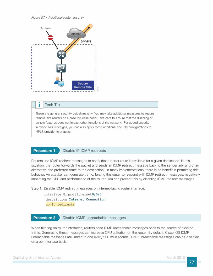
Deploying Direct Internet Access March 201577
Figure 57 - Additional router security
13
05
Internet
SecureRemote Site
DMVPN
Exploits
These are general security guidelines only. You may take additional measures to secure remote-site routers on a case-by-case basis. Take care to ensure that the disabling of certain features does not impact other functions of the network. For added security in hybrid IWAN designs, you can also apply these additional security configurations to MPLS provider interfaces.
Tech Tip
Procedure 1 Disable IP ICMP redirects
Routers use ICMP redirect messages to notify that a better route is available for a given destination. In this situation, the router forwards the packet and sends an ICMP redirect message back to the sender advising of an alternative and preferred route to the destination. In many implementations, there is no benefit in permitting this behavior. An attacker can generate traffic, forcing the router to respond with ICMP redirect messages, negatively impacting the CPU and performance of the router. You can prevent this by disabling ICMP redirect messages.
Step 1: Disable ICMP redirect messages on Internet-facing router interface.
interface GigabitEthernet0/0/0 description Internet Connection no ip redirects
Procedure 2 Disable ICMP unreachable messages
When filtering on router interfaces, routers send ICMP unreachable messages back to the source of blocked traffic. Generating these messages can increase CPU utilization on the router. By default, Cisco IOS ICMP unreachable messages are limited to one every 500 milliseconds. ICMP unreachable messages can be disabled on a per interface basis.
Deploying Direct Internet Access March 201578
Step 1: Disable ICMP unreachable messages on Internet-facing router interface.
interface GigabitEthernet0/0/0 description Internet Connection no ip unreachables
Procedure 3 Disable Proxy ARP
Proxy ARP allows the router to respond to ARP request for hosts other than itself. Proxy ARP can help machines on a subnet reach remote subnets without configuring routing or a default gateway as defined in RFC 1027. Disadvantages to using proxy ARP:
• An attacker can impact available memory by sending a large number of ARP requests.
• A router is also susceptible to man-in-the-middle attacks where a host on the network could be used to spoof the MAC address of the router, resulting in unsuspecting hosts sending traffic to the attacker.
You can disable proxy ARP by using the interface configuration command.
Step 1: Disable proxy ARP on Internet-facing router interface.
interface GigabitEthernet0/0/0 description Internet Connection no ip proxy-arp
Procedure 4 Disable unused router services
As a security best practice, you should disable all unnecessary services that could be used to launch DoS and other attacks. Many unused services that pose a security threat are disabled by default in current Cisco IOS versions.
Step 1: Disable MOP on Internet-facing router interface.
interface GigabitEthernet0/0/0 description Internet Connection no mop enabled
Step 2: Disable PAD service globally on the router.
no service pad
Step 3: Prevent the router from attempting to locate a configuration file via TFTP globally on the router.
no service config
Deploying Direct Internet Access March 201579
Procedure 5 Disable CDP and LLDP
Attackers can use CDP and LLDP for reconnaissance and network mapping. CDP is a network protocol that is used to discover other CDP-enabled devices. CDP is often used by NMS and for troubleshooting networking problems. LLDP is an IEEE protocol that is defined in 802.1AB and is very similar to CDP. You should disable CDP and LLDP on router interfaces that connect to untrusted networks.
Step 1: Disable CDP on Internet-facing router interface.
interface GigabitEthernet0/0/0 description Internet Connection no cdp enable
Step 2: Disable LLDP on Internet-facing router interface.
interface GigabitEthernet0/0/0 description Internet Connection no lldp transmit
no lldp receive
Procedure 6 Enable keepalives for TCP sessions
This configuration enables TCP keepalives on inbound connections to the router and outbound connections from the router. This ensures that the device on the remote end of the connection is still accessible and half-open or orphaned connections are removed from the router.
Step 1: Enable the TCP keepalives service for inbound and outbound connections globally on the router.
service tcp-keepalives-in
service tcp-keepalives-out
Procedure 7 Configure internal-network floating static routes
In the event the DMVPN tunnel to the hub site fails, you will want to ensure traffic destined to internal networks does not follow the local Internet default route. It’s best to have the network fail closed to prevent possible security implications and unwanted routing behavior.
Configuring floating static routes to null zero with an AD of 254 ensures that all internal subnets route to null0 in the event of tunnel failure.
Step 1: Configure static route for internal network subnets.
ip route 10.0.0.0 255.0.0.0 null0 254
Configure the appropriate number of null 0 routes for internal network ranges, using summaries when possible for your specific network environment.
Tech Tip
Deploying Direct Internet Access March 201580
Procedure 8 Enable Internet interface
Now that the security configurations are complete, you can enable the Internet-facing interface.
Step 1: Enable the Internet-facing router interface.
interface GigabitEthernet0/0/0 description Internet Connection no shutdown
Configuring ISP Black-Hole Routing Detection
1. Configure ISP black-hole routing detection
PR
OC
ESS
In many cases you will need to ensure connectivity issues with your ISP does not cause black-hole routing conditions. Failure conditions can exist where the DHCP address and routes are not removed from the remote-site router when connectivity issues exist with the broadband service or local premise equipment. There may also be circumstances if certain services are unreachable within via the local ISP connection that you want to reroute to a secondary Internet service.
This configuration requires you to turn off Performance Routing (PfR) load-balancing on the Hub Master Controller. If PfR load-balancing is not turned off, the traffic will fail over to the central site Internet path, but it will not return to the local DIA interface after the failure condition is resolved.
Tech Tip
If central Internet fallback is required, configure one or more of the following options on the secondary router.
Procedure 1 Configure ISP black-hole routing detection
Option 1: DMVPN Tunnel State TrackingIn this solution, the DMVPN tunnel state is used to monitor the status of the ISP connection used as the primary path for local Internet traffic. In this example, a “down” state of the tunnel interface triggers the removal of the default route via an EEM script. If tunnel state is “up,” the route will remain.
With this method a failure or maintenance at the central site can cause a failover event where the route is removed due to tunnel state change and the local Internet connection remains active at the remote site. In hybrid configurations this can cause failover to Central Internet for multiple sites. It is recommended that you use the other options presented in this guide for hybrid DIA configurations.
Tech Tip
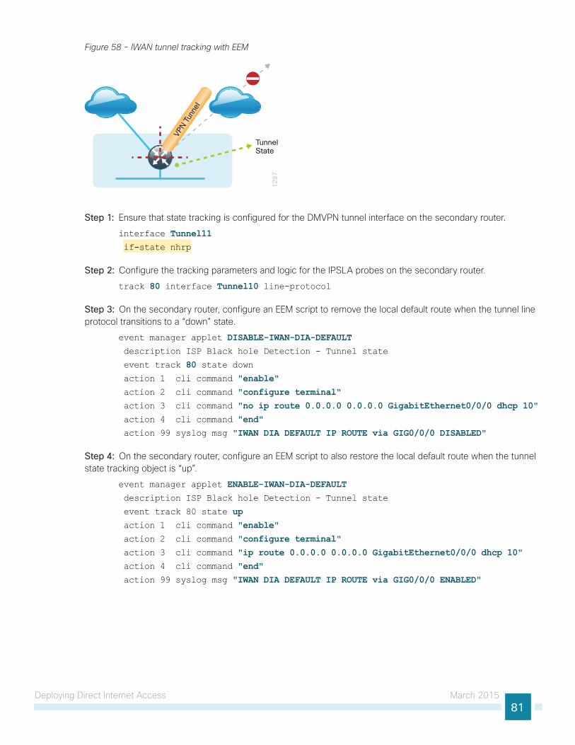
Deploying Direct Internet Access March 201581
Figure 58 - IWAN tunnel tracking with EEM
12
97
VPN T
unne
l
TunnelState
Step 1: Ensure that state tracking is configured for the DMVPN tunnel interface on the secondary router.
interface Tunnel11 if-state nhrp
Step 2: Configure the tracking parameters and logic for the IPSLA probes on the secondary router.
track 80 interface Tunnel10 line-protocol
Step 3: On the secondary router, configure an EEM script to remove the local default route when the tunnel line protocol transitions to a “down” state.
event manager applet DISABLE-IWAN-DIA-DEFAULT description ISP Black hole Detection - Tunnel state
event track 80 state down action 1 cli command "enable" action 2 cli command "configure terminal" action 3 cli command "no ip route 0.0.0.0 0.0.0.0 GigabitEthernet0/0/0 dhcp 10" action 4 cli command "end" action 99 syslog msg "IWAN DIA DEFAULT IP ROUTE via GIG0/0/0 DISABLED"
Step 4: On the secondary router, configure an EEM script to also restore the local default route when the tunnel state tracking object is “up”.
event manager applet ENABLE-IWAN-DIA-DEFAULT description ISP Black hole Detection - Tunnel state
event track 80 state up action 1 cli command "enable" action 2 cli command "configure terminal" action 3 cli command "ip route 0.0.0.0 0.0.0.0 GigabitEthernet0/0/0 dhcp 10" action 4 cli command "end" action 99 syslog msg "IWAN DIA DEFAULT IP ROUTE via GIG0/0/0 ENABLED"
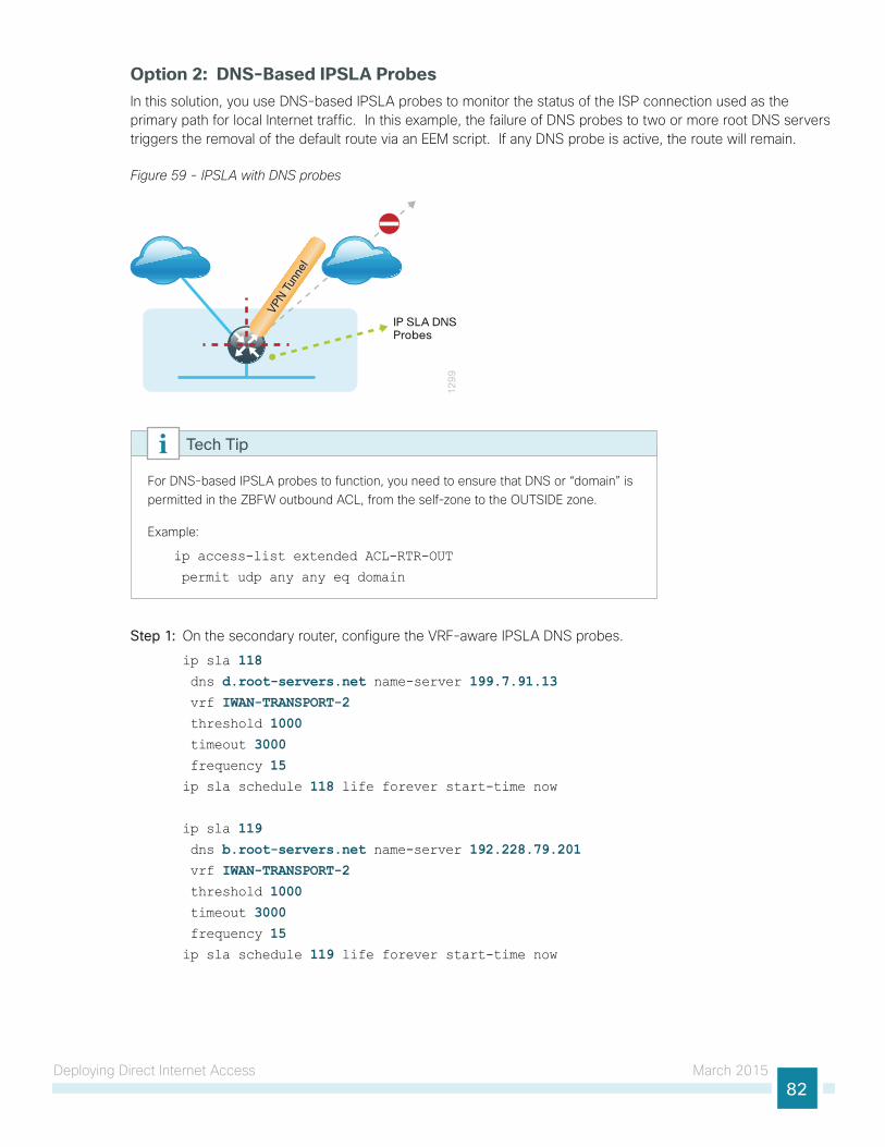
Deploying Direct Internet Access March 201582
Option 2: DNS-Based IPSLA ProbesIn this solution, you use DNS-based IPSLA probes to monitor the status of the ISP connection used as the primary path for local Internet traffic. In this example, the failure of DNS probes to two or more root DNS servers triggers the removal of the default route via an EEM script. If any DNS probe is active, the route will remain.
Figure 59 - IPSLA with DNS probes
12
99
VPN T
unne
l
IP SLA DNSProbes
For DNS-based IPSLA probes to function, you need to ensure that DNS or “domain” is permitted in the ZBFW outbound ACL, from the self-zone to the OUTSIDE zone.
Example:
ip access-list extended ACL-RTR-OUT
permit udp any any eq domain
Tech Tip
Step 1: On the secondary router, configure the VRF-aware IPSLA DNS probes.
ip sla 118 dns d.root-servers.net name-server 199.7.91.13 vrf IWAN-TRANSPORT-2 threshold 1000 timeout 3000 frequency 15ip sla schedule 118 life forever start-time now
ip sla 119 dns b.root-servers.net name-server 192.228.79.201 vrf IWAN-TRANSPORT-2 threshold 1000 timeout 3000 frequency 15ip sla schedule 119 life forever start-time now
Deploying Direct Internet Access March 201583
When configuring DNS probes, you should specify the hostname of the DNS server itself. That asks the DNS server to resolve for itself, allowing the use of root DNS servers.
Tech Tip
Step 2: On the secondary router, configure the tracking parameters and logic for the IPSLA probes.
track 73 ip sla 118 reachabilitytrack 74 ip sla 119 reachability!
track 100 list boolean or object 73 object 74
Step 3: On the secondary router, configure an EEM script to remove the route in the event of DNS probe failure.
event manager applet DISABLE-IWAN-DIA-DEFAULT description ISP Black hole Detection - Tunnel state
event track 100 state down action 1 cli command "enable" action 2 cli command "configure terminal" action 3 cli command "no ip route 0.0.0.0 0.0.0.0 GigabitEthernet0/0/0 dhcp 10" action 4 cli command "end"
action 99 syslog msg "IWAN DIA DEFAULT IP ROUTE via GIG0/0/0 DISABLED"
Step 4: On the secondary router, configure an EEM script to also restore the local default route when the DNS probes are active.
event manager applet ENABLE-IWAN-DIA-DEFAULT description ISP Black hole Detection - Tunnel state
event track 100 state up action 1 cli command "enable" action 2 cli command "configure terminal" action 3 cli command "ip route 0.0.0.0 0.0.0.0 GigabitEthernet0/0/0 dhcp 10" action 4 cli command "end" action 99 syslog msg "IWAN DIA DEFAULT IP ROUTE via GIG0/0/0 ENABLED"
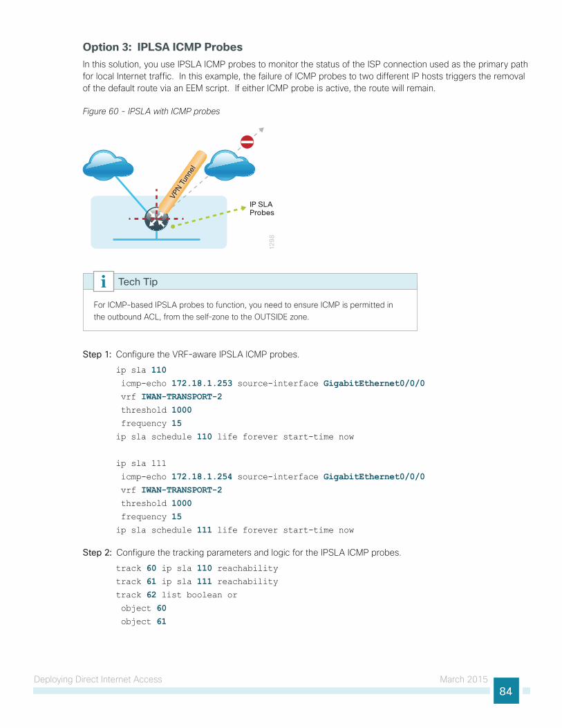
Deploying Direct Internet Access March 201584
Option 3: IPLSA ICMP ProbesIn this solution, you use IPSLA ICMP probes to monitor the status of the ISP connection used as the primary path for local Internet traffic. In this example, the failure of ICMP probes to two different IP hosts triggers the removal of the default route via an EEM script. If either ICMP probe is active, the route will remain.
Figure 60 - IPSLA with ICMP probes
12
98
VPN T
unne
l
IP SLAProbes
For ICMP-based IPSLA probes to function, you need to ensure ICMP is permitted in the outbound ACL, from the self-zone to the OUTSIDE zone.
Tech Tip
Step 1: Configure the VRF-aware IPSLA ICMP probes.
ip sla 110 icmp-echo 172.18.1.253 source-interface GigabitEthernet0/0/0 vrf IWAN-TRANSPORT-2 threshold 1000 frequency 15ip sla schedule 110 life forever start-time now
ip sla 111
icmp-echo 172.18.1.254 source-interface GigabitEthernet0/0/0 vrf IWAN-TRANSPORT-2 threshold 1000 frequency 15ip sla schedule 111 life forever start-time now
Step 2: Configure the tracking parameters and logic for the IPSLA ICMP probes.
track 60 ip sla 110 reachabilitytrack 61 ip sla 111 reachabilitytrack 62 list boolean or object 60 object 61
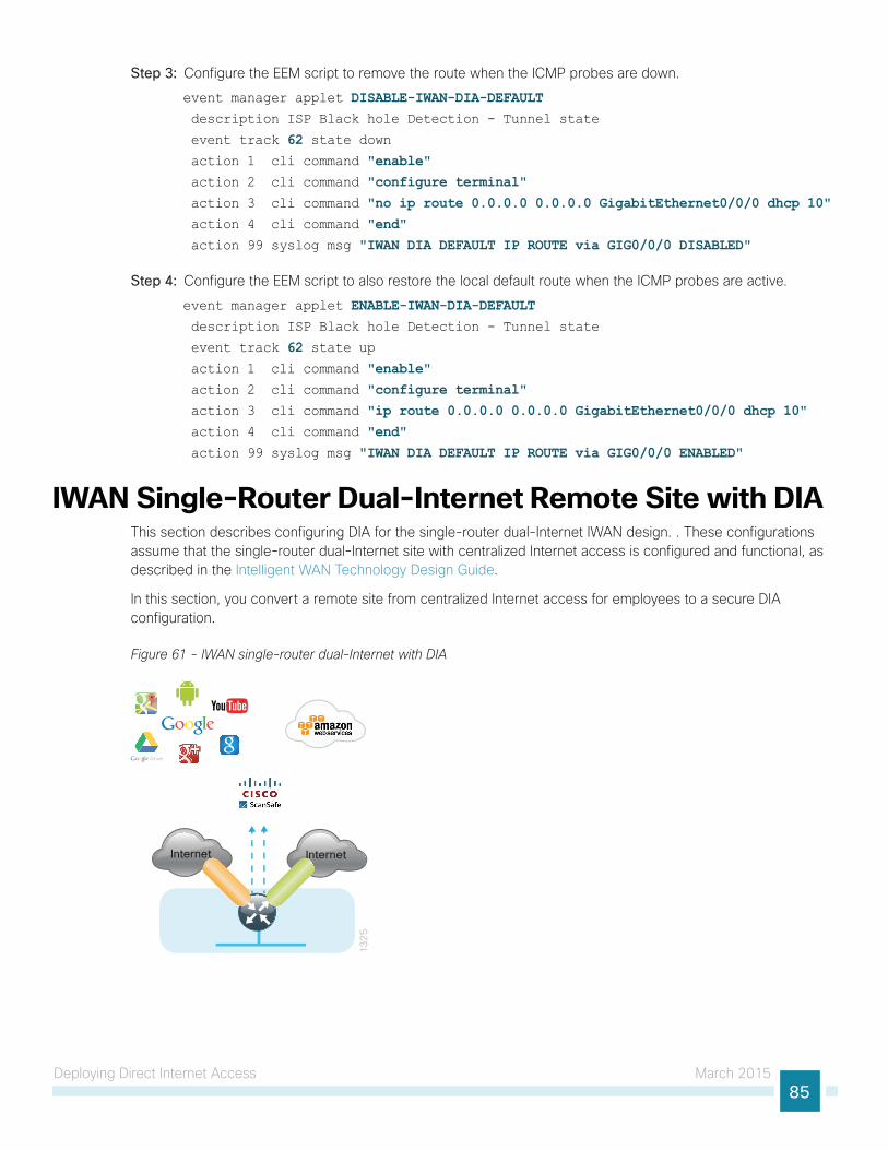
Deploying Direct Internet Access March 201585
Step 3: Configure the EEM script to remove the route when the ICMP probes are down.
event manager applet DISABLE-IWAN-DIA-DEFAULT description ISP Black hole Detection - Tunnel state
event track 62 state down action 1 cli command "enable" action 2 cli command "configure terminal" action 3 cli command "no ip route 0.0.0.0 0.0.0.0 GigabitEthernet0/0/0 dhcp 10" action 4 cli command "end" action 99 syslog msg "IWAN DIA DEFAULT IP ROUTE via GIG0/0/0 DISABLED"
Step 4: Configure the EEM script to also restore the local default route when the ICMP probes are active.
event manager applet ENABLE-IWAN-DIA-DEFAULT description ISP Black hole Detection - Tunnel state
event track 62 state up action 1 cli command "enable" action 2 cli command "configure terminal" action 3 cli command "ip route 0.0.0.0 0.0.0.0 GigabitEthernet0/0/0 dhcp 10" action 4 cli command "end" action 99 syslog msg "IWAN DIA DEFAULT IP ROUTE via GIG0/0/0 ENABLED"
IWAN Single-Router Dual-Internet Remote Site with DIAThis section describes configuring DIA for the single-router dual-Internet IWAN design. . These configurations assume that the single-router dual-Internet site with centralized Internet access is configured and functional, as described in the Intelligent WAN Technology Design Guide.
In this section, you convert a remote site from centralized Internet access for employees to a secure DIA configuration.
Figure 61 - IWAN single-router dual-Internet with DIA
13
25
Internet Internet
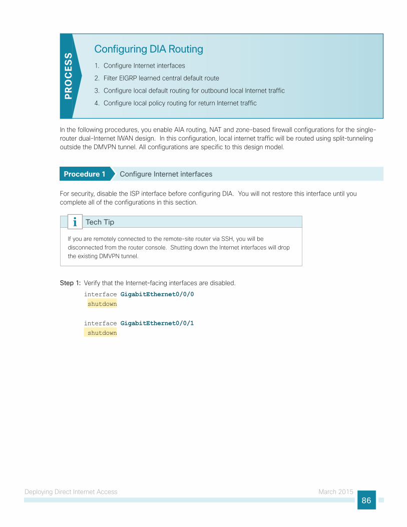
Deploying Direct Internet Access March 201586
Configuring DIA Routing
1. Configure Internet interfaces
2. Filter EIGRP learned central default route
3. Configure local default routing for outbound local Internet traffic
4. Configure local policy routing for return Internet traffic
PR
OC
ESS
In the following procedures, you enable AIA routing, NAT and zone-based firewall configurations for the single-router dual-Internet IWAN design. In this configuration, local internet traffic will be routed using split-tunneling outside the DMVPN tunnel. All configurations are specific to this design model.
Procedure 1 Configure Internet interfaces
For security, disable the ISP interface before configuring DIA. You will not restore this interface until you complete all of the configurations in this section.
If you are remotely connected to the remote-site router via SSH, you will be disconnected from the router console. Shutting down the Internet interfaces will drop the existing DMVPN tunnel.
Tech Tip
Step 1: Verify that the Internet-facing interfaces are disabled.
interface GigabitEthernet0/0/0 shutdown
interface GigabitEthernet0/0/1 shutdown
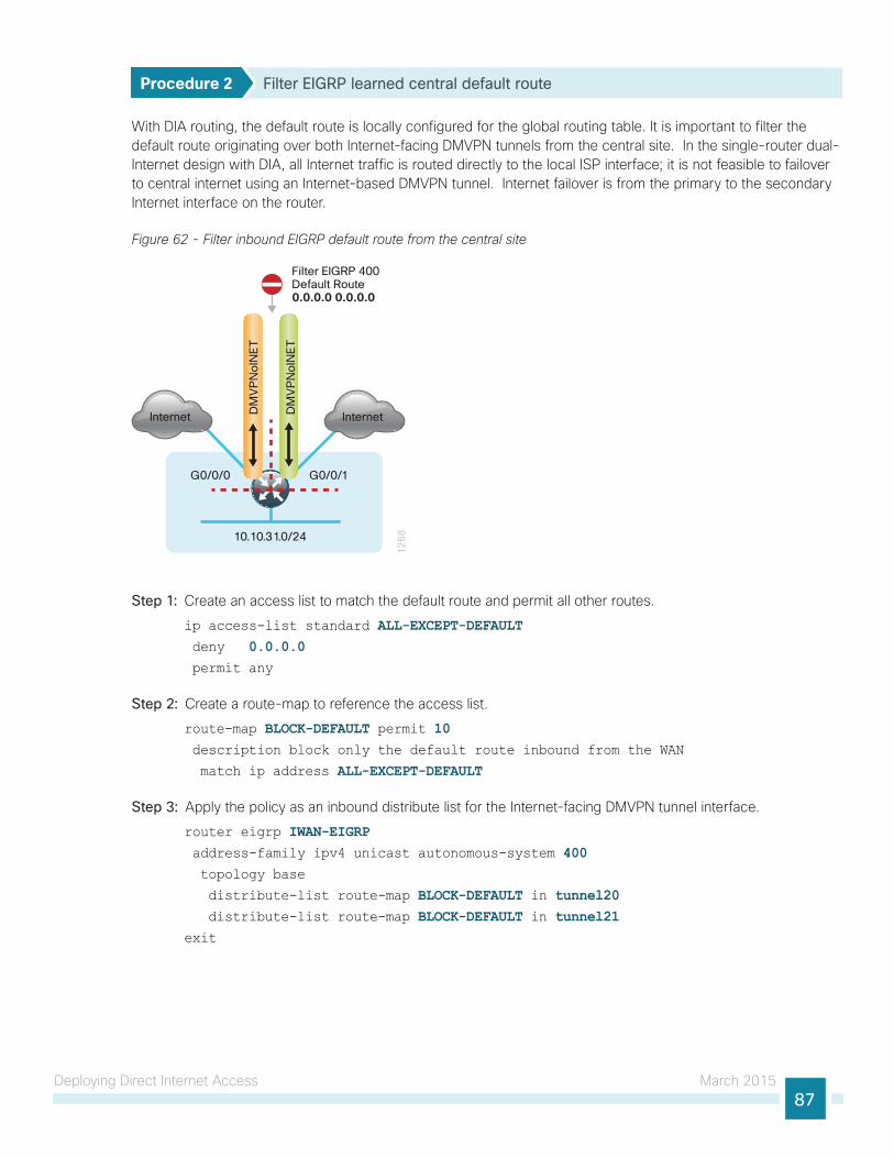
Deploying Direct Internet Access March 201587
Procedure 2 Filter EIGRP learned central default route
With DIA routing, the default route is locally configured for the global routing table. It is important to filter the default route originating over both Internet-facing DMVPN tunnels from the central site. In the single-router dual-Internet design with DIA, all Internet traffic is routed directly to the local ISP interface; it is not feasible to failover to central internet using an Internet-based DMVPN tunnel. Internet failover is from the primary to the secondary Internet interface on the router.
Figure 62 - Filter inbound EIGRP default route from the central site
10.10.31.0/24
12
68
InternetDM
VP
No
INE
T
DM
VP
No
INE
T
G0/0/0
Filter EIGRP 400Default Route0.0.0.0 0.0.0.0
G0/0/1
Internet
Step 1: Create an access list to match the default route and permit all other routes.
ip access-list standard ALL-EXCEPT-DEFAULT deny 0.0.0.0 permit any
Step 2: Create a route-map to reference the access list.
route-map BLOCK-DEFAULT permit 10 description block only the default route inbound from the WAN
match ip address ALL-EXCEPT-DEFAULT
Step 3: Apply the policy as an inbound distribute list for the Internet-facing DMVPN tunnel interface.
router eigrp IWAN-EIGRP address-family ipv4 unicast autonomous-system 400 topology base
distribute-list route-map BLOCK-DEFAULT in tunnel20 distribute-list route-map BLOCK-DEFAULT in tunnel21exit
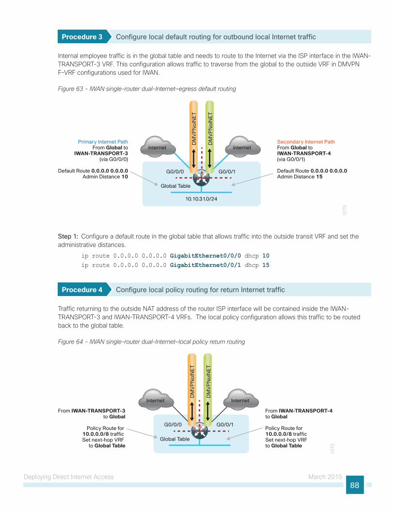
Deploying Direct Internet Access March 201588
Procedure 3 Configure local default routing for outbound local Internet traffic
Internal employee traffic is in the global table and needs to route to the Internet via the ISP interface in the IWAN-TRANSPORT-3 VRF. This configuration allows traffic to traverse from the global to the outside VRF in DMVPN F-VRF configurations used for IWAN.
Figure 63 - IWAN single-router dual-Internet—egress default routing
10.10.31.0/24
12
70
Internet
DM
VP
No
INE
T
DM
VP
No
INE
T
Secondary Internet PathFrom Global to IWAN-TRANSPORT-4(via G0/0/1)
Default Route 0.0.0.0 0.0.0.0Admin Distance 15
Primary Internet PathFrom Global to
IWAN-TRANSPORT-3(via G0/0/0)
Default Route 0.0.0.0 0.0.0.0Admin Distance 10
Internet
G0/0/0 G0/0/1
Global Table
Step 1: Configure a default route in the global table that allows traffic into the outside transit VRF and set the administrative distances.
ip route 0.0.0.0 0.0.0.0 GigabitEthernet0/0/0 dhcp 10ip route 0.0.0.0 0.0.0.0 GigabitEthernet0/0/1 dhcp 15
Procedure 4 Configure local policy routing for return Internet traffic
Traffic returning to the outside NAT address of the router ISP interface will be contained inside the IWAN-TRANSPORT-3 and IWAN-TRANSPORT-4 VRFs. The local policy configuration allows this traffic to be routed back to the global table.
Figure 64 - IWAN single-router dual-Internet—local policy return routing
Global Table
12
72
Internet
DM
VP
No
INE
T
DM
VP
No
INE
T
From IWAN-TRANSPORT-4to Global
Policy Route for 10.0.0.0/8 traffic Set next-hop VRF to Global Table
From IWAN-TRANSPORT-3to Global
Policy Route for 10.0.0.0/8 traffic Set next-hop VRF
to Global Table
Internet
G0/0/0 G0/0/1
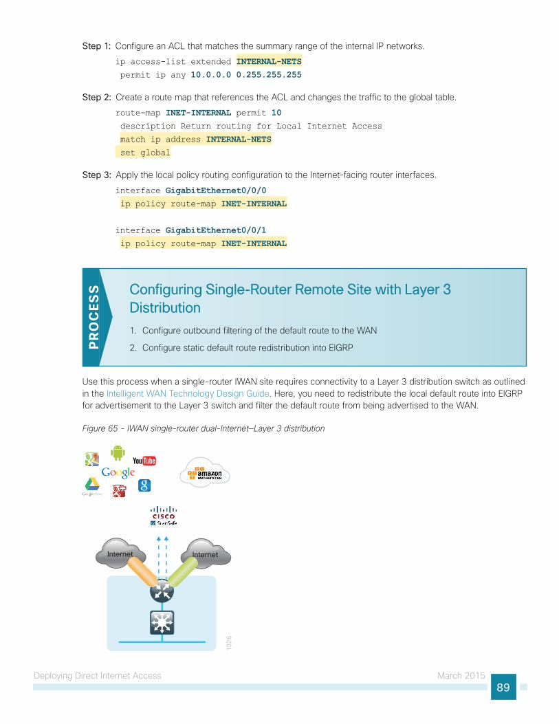
Deploying Direct Internet Access March 201589
Step 1: Configure an ACL that matches the summary range of the internal IP networks.
ip access-list extended INTERNAL-NETS permit ip any 10.0.0.0 0.255.255.255
Step 2: Create a route map that references the ACL and changes the traffic to the global table.
route-map INET-INTERNAL permit 10 description Return routing for Local Internet Access
match ip address INTERNAL-NETS set global
Step 3: Apply the local policy routing configuration to the Internet-facing router interfaces.
interface GigabitEthernet0/0/0 ip policy route-map INET-INTERNAL
interface GigabitEthernet0/0/1 ip policy route-map INET-INTERNAL
Configuring Single-Router Remote Site with Layer 3 Distribution
1. Configure outbound filtering of the default route to the WAN
2. Configure static default route redistribution into EIGRPPR
OC
ESS
Use this process when a single-router IWAN site requires connectivity to a Layer 3 distribution switch as outlined in the Intelligent WAN Technology Design Guide. Here, you need to redistribute the local default route into EIGRP for advertisement to the Layer 3 switch and filter the default route from being advertised to the WAN.
Figure 65 - IWAN single-router dual-Internet—Layer 3 distribution
13
26
Internet Internet
Deploying Direct Internet Access March 201590
Procedure 1 Configure outbound filtering of the default route to the WAN
Perform these steps when connecting a single-router to a Layer 3 distribution switch.
Step 1: Configure an access list to deny the default route and permit all over routes.
ip access-list standard ALL-EXCEPT-DEFAULT deny 0.0.0.0 permit any
Step 2: Add an instance after the existing route map named “ROUTE-LIST” and reference the access list that denies the default route and permits all other routes. There should be an instance of this route map from the IWAN foundation configuration. This statement should go between the existing statements.
route-map ROUTE-LIST deny 20 description Block Local Internet Default route out to the WAN
match ip address DEFAULT-ONLY
Step 3: On both routers, ensure that the route map is applied as an outbound distribution list on the DMVPN tunnel interface. Apply this as part of the foundational configuration for dual-router egress filtering.
router eigrp IWAN-EIGRP !
address-family ipv4 unicast autonomous-system 400 topology base
distribute-list route-map ROUTE-LIST out Tunnel20 distribute-list route-map ROUTE-LIST out Tunnel21 exit-af-topology
exit-address-family
Procedure 2 Configure static default route redistribution into EIGRP
Perform these steps when connecting a single router to a Layer 3 distribution switch.
Step 1: Configure an access list to match the default route for redistribution.
ip access-list standard DEFAULT-ONLY permit 0.0.0.0
Step 2: Configure a route map for static redistribution, referencing the access list that matches the static default route.
route-map STATIC-IN permit 10 description Redistribute local default route
match ip address DEFAULT-ONLY
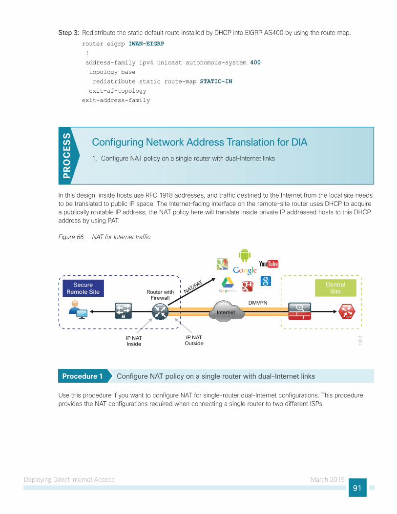
Deploying Direct Internet Access March 201591
Step 3: Redistribute the static default route installed by DHCP into EIGRP AS400 by using the route map.
router eigrp IWAN-EIGRP !
address-family ipv4 unicast autonomous-system 400 topology base
redistribute static route-map STATIC-IN exit-af-topology
exit-address-family
Configuring Network Address Translation for DIA
1. Configure NAT policy on a single router with dual-Internet links
PR
OC
ESS
In this design, inside hosts use RFC 1918 addresses, and traffic destined to the Internet from the local site needs to be translated to public IP space. The Internet-facing interface on the remote-site router uses DHCP to acquire a publically routable IP address; the NAT policy here will translate inside private IP addressed hosts to this DHCP address by using PAT.
Figure 66 - NAT for Internet traffic
13
01
Internet
DMVPN
IP NATInside
Router withFirewall
IP NATOutside
CentralSite
SecureRemote Site NAT/PAT
Procedure 1 Configure NAT policy on a single router with dual-Internet links
Use this procedure if you want to configure NAT for single-router dual-Internet configurations. This procedure provides the NAT configurations required when connecting a single router to two different ISPs.
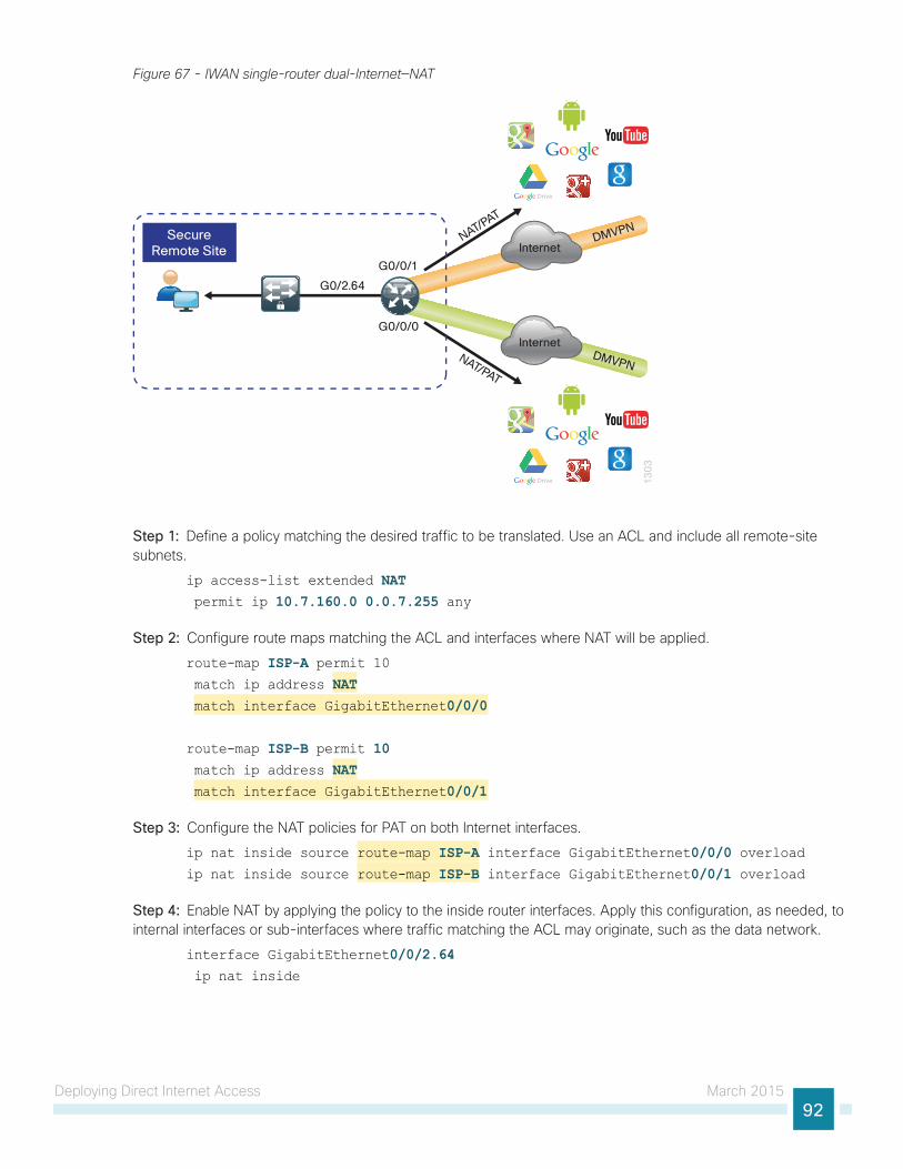
Deploying Direct Internet Access March 201592
Figure 67 - IWAN single-router dual-Internet—NAT
13
03
InternetDMVPN
G0/0/1
SecureRemote Site
G0/2.64
NAT/PAT
G0/0/0Internet
DMVPNNAT/PAT
Step 1: Define a policy matching the desired traffic to be translated. Use an ACL and include all remote-site subnets.
ip access-list extended NAT permit ip 10.7.160.0 0.0.7.255 any
Step 2: Configure route maps matching the ACL and interfaces where NAT will be applied.
route-map ISP-A permit 10 match ip address NAT match interface GigabitEthernet0/0/0
route-map ISP-B permit 10 match ip address NAT match interface GigabitEthernet0/0/1
Step 3: Configure the NAT policies for PAT on both Internet interfaces.
ip nat inside source route-map ISP-A interface GigabitEthernet0/0/0 overloadip nat inside source route-map ISP-B interface GigabitEthernet0/0/1 overload
Step 4: Enable NAT by applying the policy to the inside router interfaces. Apply this configuration, as needed, to internal interfaces or sub-interfaces where traffic matching the ACL may originate, such as the data network.
interface GigabitEthernet0/0/2.64 ip nat inside
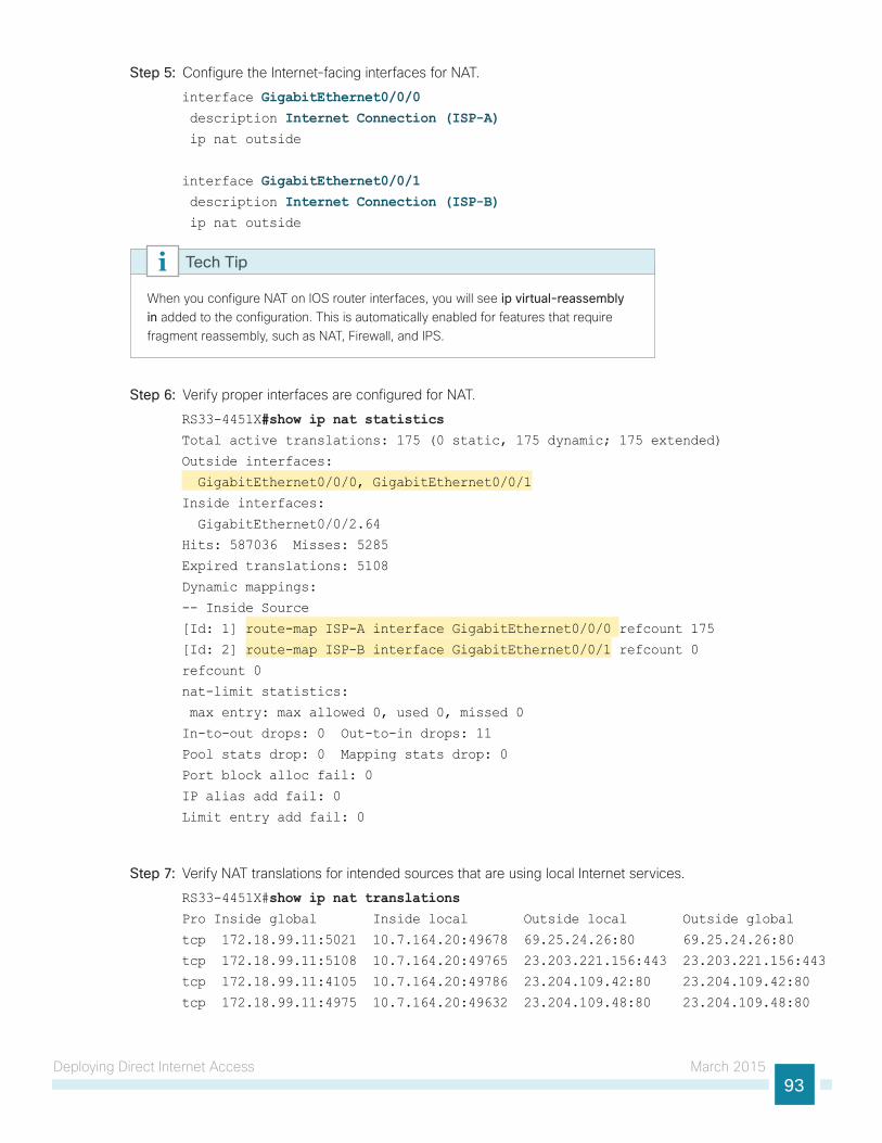
Deploying Direct Internet Access March 201593
Step 5: Configure the Internet-facing interfaces for NAT.
interface GigabitEthernet0/0/0 description Internet Connection (ISP-A) ip nat outside
interface GigabitEthernet0/0/1 description Internet Connection (ISP-B) ip nat outside
When you configure NAT on IOS router interfaces, you will see ip virtual-reassembly in added to the configuration. This is automatically enabled for features that require fragment reassembly, such as NAT, Firewall, and IPS.
Tech Tip
Step 6: Verify proper interfaces are configured for NAT.
RS33-4451X#show ip nat statisticsTotal active translations: 175 (0 static, 175 dynamic; 175 extended)
Outside interfaces:
GigabitEthernet0/0/0, GigabitEthernet0/0/1
Inside interfaces:
GigabitEthernet0/0/2.64
Hits: 587036 Misses: 5285
Expired translations: 5108
Dynamic mappings:
-- Inside Source
[Id: 1] route-map ISP-A interface GigabitEthernet0/0/0 refcount 175
[Id: 2] route-map ISP-B interface GigabitEthernet0/0/1 refcount 0
refcount 0
nat-limit statistics:
max entry: max allowed 0, used 0, missed 0
In-to-out drops: 0 Out-to-in drops: 11
Pool stats drop: 0 Mapping stats drop: 0
Port block alloc fail: 0
IP alias add fail: 0
Limit entry add fail: 0
Step 7: Verify NAT translations for intended sources that are using local Internet services.
RS33-4451X#show ip nat translations Pro Inside global Inside local Outside local Outside global
tcp 172.18.99.11:5021 10.7.164.20:49678 69.25.24.26:80 69.25.24.26:80
tcp 172.18.99.11:5108 10.7.164.20:49765 23.203.221.156:443 23.203.221.156:443
tcp 172.18.99.11:4105 10.7.164.20:49786 23.204.109.42:80 23.204.109.42:80
tcp 172.18.99.11:4975 10.7.164.20:49632 23.204.109.48:80 23.204.109.48:80
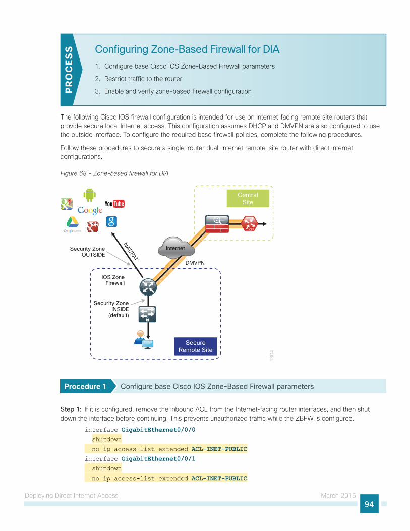
Deploying Direct Internet Access March 201594
Configuring Zone-Based Firewall for DIA
1. Configure base Cisco IOS Zone-Based Firewall parameters
2. Restrict traffic to the router
3. Enable and verify zone-based firewall configurationPR
OC
ESS
The following Cisco IOS firewall configuration is intended for use on Internet-facing remote site routers that provide secure local Internet access. This configuration assumes DHCP and DMVPN are also configured to use the outside interface. To configure the required base firewall policies, complete the following procedures.
Follow these procedures to secure a single-router dual-Internet remote-site router with direct Internet configurations.
Figure 68 - Zone-based firewall for DIA
13
04
Internet
CentralSite
SecureRemote Site
IOS ZoneFirewall
DMVPN
Security ZoneOUTSIDE
Security ZoneINSIDE
(default)
NAT/PAT
Procedure 1 Configure base Cisco IOS Zone-Based Firewall parameters
Step 1: If it is configured, remove the inbound ACL from the Internet-facing router interfaces, and then shut down the interface before continuing. This prevents unauthorized traffic while the ZBFW is configured.
interface GigabitEthernet0/0/0 shutdown
no ip access-list extended ACL-INET-PUBLICinterface GigabitEthernet0/0/1 shutdown
no ip access-list extended ACL-INET-PUBLIC
Deploying Direct Internet Access March 201595
Step 2: Define security zones. A zone is a named group of interfaces that have similar functions or security requirements. This example defines the names of the three basic security zones identified.
Step 3: This example has two outside interfaces that are both in a unique VRF. In this situation, you must define two security zones; you cannot define a single security zones to interfaces in different VRFs.
Step 4: For simplicity, this design uses the “default” security zone for inside interfaces. Once the default zone has been defined, all interfaces not explicitly configured as members of a security zone will automatically be part of the default security zone.
zone security defaultzone security OUTSIDE-Azone security OUTSIDE-B
This design uses the “default” zone for all inside interfaces; traffic can flow between all interfaces in the default zone.
An interface not defined as part of a security zone is automatically part of the “default” zone. In this configuration, all undefined interface DMVPN tunnels, transit sub-interfaces, and service interfaces such as Cisco UCS-E, and SRE interfaces are included as part of the default zone.
Be aware that any interface that is removed from a defined security zone will be automatically placed into the default zone. In this configuration, that interface will be treated as an “inside” zone and have access to the internal routing domain.
Tech Tip
Step 5: Define a class map to match specific protocols. Class-maps apply match-any or match-all operators in order to determine how to apply the match criteria to the class. If match-any is specified, traffic must meet at least one of the match criteria in the class-map to be included in the class. If match-all is specified, traffic must meet all of the match criteria to be included in the class.
class-map type inspect match-any INSIDE-TO-OUTSIDE-CLASS match protocol ftp match protocol tcp match protocol udp match protocol icmp
Protocols that use single ports (such as HTTP, telnet, SSH, etc.) can be statefully allowed with tcp inspection alone by using the match protocol tcp command.
Protocols such as ftp that use multiple ports (one for control and another for data) require application inspection in order to enable dynamic adjustments to the active firewall policy. The specific TCP ports that are required for the application are allowed for short durations, as necessary.
Tech Tip
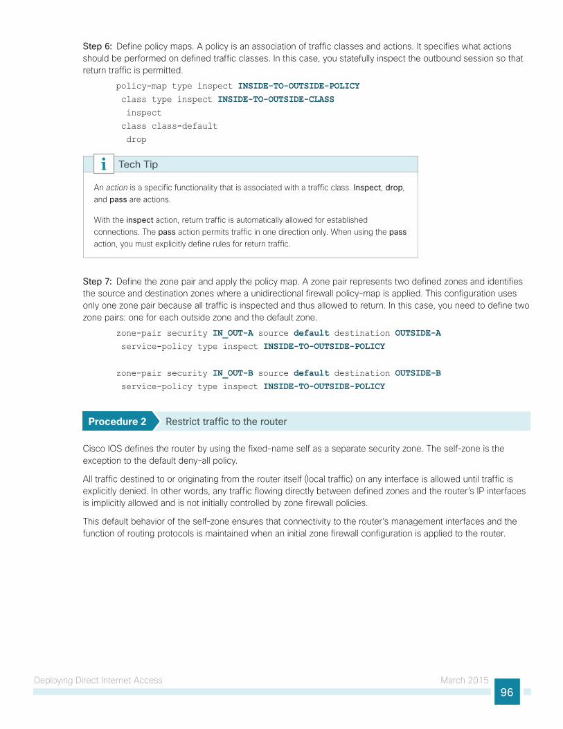
Deploying Direct Internet Access March 201596
Step 6: Define policy maps. A policy is an association of traffic classes and actions. It specifies what actions should be performed on defined traffic classes. In this case, you statefully inspect the outbound session so that return traffic is permitted.
policy-map type inspect INSIDE-TO-OUTSIDE-POLICY class type inspect INSIDE-TO-OUTSIDE-CLASS inspect
class class-default
drop
An action is a specific functionality that is associated with a traffic class. Inspect, drop, and pass are actions.
With the inspect action, return traffic is automatically allowed for established connections. The pass action permits traffic in one direction only. When using the pass action, you must explicitly define rules for return traffic.
Tech Tip
Step 7: Define the zone pair and apply the policy map. A zone pair represents two defined zones and identifies the source and destination zones where a unidirectional firewall policy-map is applied. This configuration uses only one zone pair because all traffic is inspected and thus allowed to return. In this case, you need to define two zone pairs: one for each outside zone and the default zone.
zone-pair security IN_OUT-A source default destination OUTSIDE-A service-policy type inspect INSIDE-TO-OUTSIDE-POLICY
zone-pair security IN_OUT-B source default destination OUTSIDE-B service-policy type inspect INSIDE-TO-OUTSIDE-POLICY
Procedure 2 Restrict traffic to the router
Cisco IOS defines the router by using the fixed-name self as a separate security zone. The self-zone is the exception to the default deny-all policy.
All traffic destined to or originating from the router itself (local traffic) on any interface is allowed until traffic is explicitly denied. In other words, any traffic flowing directly between defined zones and the router’s IP interfaces is implicitly allowed and is not initially controlled by zone firewall policies.
This default behavior of the self-zone ensures that connectivity to the router’s management interfaces and the function of routing protocols is maintained when an initial zone firewall configuration is applied to the router.
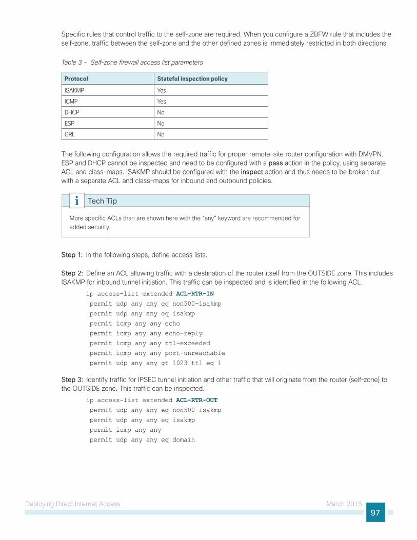
Deploying Direct Internet Access March 201597
Specific rules that control traffic to the self-zone are required. When you configure a ZBFW rule that includes the self-zone, traffic between the self-zone and the other defined zones is immediately restricted in both directions.
Table 3 - Self-zone firewall access list parameters
Protocol Stateful inspection policy
ISAKMP Yes
ICMP Yes
DHCP No
ESP No
GRE No
The following configuration allows the required traffic for proper remote-site router configuration with DMVPN. ESP and DHCP cannot be inspected and need to be configured with a pass action in the policy, using separate ACL and class-maps. ISAKMP should be configured with the inspect action and thus needs to be broken out with a separate ACL and class-maps for inbound and outbound policies.
More specific ACLs than are shown here with the “any” keyword are recommended for added security.
Tech Tip
Step 1: In the following steps, define access lists.
Step 2: Define an ACL allowing traffic with a destination of the router itself from the OUTSIDE zone. This includes ISAKMP for inbound tunnel initiation. This traffic can be inspected and is identified in the following ACL.
ip access-list extended ACL-RTR-IN permit udp any any eq non500-isakmp
permit udp any any eq isakmp
permit icmp any any echo
permit icmp any any echo-reply
permit icmp any any ttl-exceeded
permit icmp any any port-unreachable
permit udp any any gt 1023 ttl eq 1
Step 3: Identify traffic for IPSEC tunnel initiation and other traffic that will originate from the router (self-zone) to the OUTSIDE zone. This traffic can be inspected.
ip access-list extended ACL-RTR-OUT permit udp any any eq non500-isakmp
permit udp any any eq isakmp
permit icmp any any
permit udp any any eq domain
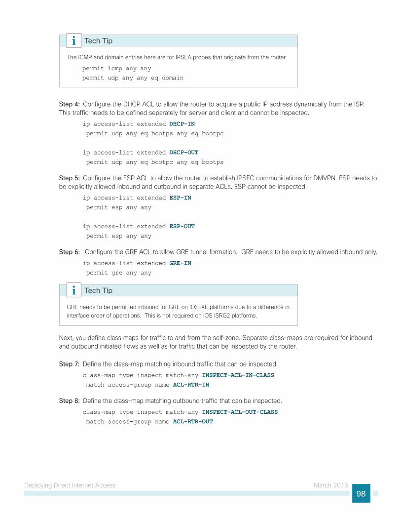
Deploying Direct Internet Access March 201598
The ICMP and domain entries here are for IPSLA probes that originate from the router.
permit icmp any any
permit udp any any eq domain
Tech Tip
Step 4: Configure the DHCP ACL to allow the router to acquire a public IP address dynamically from the ISP. This traffic needs to be defined separately for server and client and cannot be inspected.
ip access-list extended DHCP-IN permit udp any eq bootps any eq bootpc
ip access-list extended DHCP-OUT permit udp any eq bootpc any eq bootps
Step 5: Configure the ESP ACL to allow the router to establish IPSEC communications for DMVPN. ESP needs to be explicitly allowed inbound and outbound in separate ACLs. ESP cannot be inspected.
ip access-list extended ESP-IN permit esp any any
ip access-list extended ESP-OUT permit esp any any
Step 6: Configure the GRE ACL to allow GRE tunnel formation. GRE needs to be explicitly allowed inbound only.
ip access-list extended GRE-IN permit gre any any
GRE needs to be permitted inbound for GRE on IOS-XE platforms due to a difference in interface order of operations. This is not required on IOS ISRG2 platforms.
Tech Tip
Next, you define class maps for traffic to and from the self-zone. Separate class-maps are required for inbound and outbound initiated flows as well as for traffic that can be inspected by the router.
Step 7: Define the class-map matching inbound traffic that can be inspected.
class-map type inspect match-any INSPECT-ACL-IN-CLASS match access-group name ACL-RTR-IN
Step 8: Define the class-map matching outbound traffic that can be inspected.
class-map type inspect match-any INSPECT-ACL-OUT-CLASS match access-group name ACL-RTR-OUT
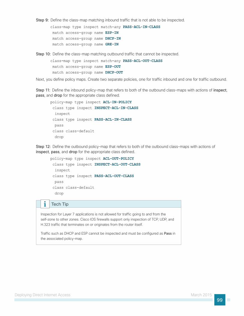
Deploying Direct Internet Access March 201599
Step 9: Define the class-map matching inbound traffic that is not able to be inspected.
class-map type inspect match-any PASS-ACL-IN-CLASS match access-group name ESP-IN match access-group name DHCP-IN match access-group name GRE-IN
Step 10: Define the class-map matching outbound traffic that cannot be inspected.
class-map type inspect match-any PASS-ACL-OUT-CLASS match access-group name ESP-OUT match access-group name DHCP-OUT
Next, you define policy maps. Create two separate policies, one for traffic inbound and one for traffic outbound.
Step 11: Define the inbound policy-map that refers to both of the outbound class-maps with actions of inspect, pass, and drop for the appropriate class defined.
policy-map type inspect ACL-IN-POLICY class type inspect INSPECT-ACL-IN-CLASS inspect
class type inspect PASS-ACL-IN-CLASS pass
class class-default
drop
Step 12: Define the outbound policy-map that refers to both of the outbound class-maps with actions of inspect, pass, and drop for the appropriate class defined.
policy-map type inspect ACL-OUT-POLICY class type inspect INSPECT-ACL-OUT-CLASS inspect
class type inspect PASS-ACL-OUT-CLASS pass
class class-default
drop
Inspection for Layer 7 applications is not allowed for traffic going to and from the self-zone to other zones. Cisco IOS firewalls support only inspection of TCP, UDP, and H.323 traffic that terminates on or originates from the router itself.
Traffic such as DHCP and ESP cannot be inspected and must be configured as Pass in the associated policy-map.
Tech Tip
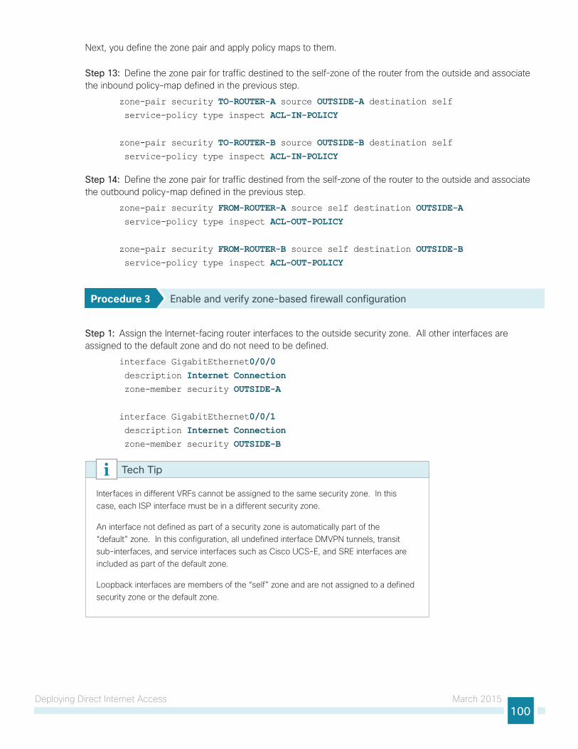
Deploying Direct Internet Access March 2015100
Next, you define the zone pair and apply policy maps to them.
Step 13: Define the zone pair for traffic destined to the self-zone of the router from the outside and associate the inbound policy-map defined in the previous step.
zone-pair security TO-ROUTER-A source OUTSIDE-A destination self service-policy type inspect ACL-IN-POLICY
zone-pair security TO-ROUTER-B source OUTSIDE-B destination self service-policy type inspect ACL-IN-POLICY
Step 14: Define the zone pair for traffic destined from the self-zone of the router to the outside and associate the outbound policy-map defined in the previous step.
zone-pair security FROM-ROUTER-A source self destination OUTSIDE-A service-policy type inspect ACL-OUT-POLICY
zone-pair security FROM-ROUTER-B source self destination OUTSIDE-B service-policy type inspect ACL-OUT-POLICY
Procedure 3 Enable and verify zone-based firewall configuration
Step 1: Assign the Internet-facing router interfaces to the outside security zone. All other interfaces are assigned to the default zone and do not need to be defined.
interface GigabitEthernet0/0/0 description Internet Connection zone-member security OUTSIDE-A
interface GigabitEthernet0/0/1 description Internet Connection zone-member security OUTSIDE-B
Interfaces in different VRFs cannot be assigned to the same security zone. In this case, each ISP interface must be in a different security zone.
An interface not defined as part of a security zone is automatically part of the “default” zone. In this configuration, all undefined interface DMVPN tunnels, transit sub-interfaces, and service interfaces such as Cisco UCS-E, and SRE interfaces are included as part of the default zone.
Loopback interfaces are members of the “self” zone and are not assigned to a defined security zone or the default zone.
Tech Tip
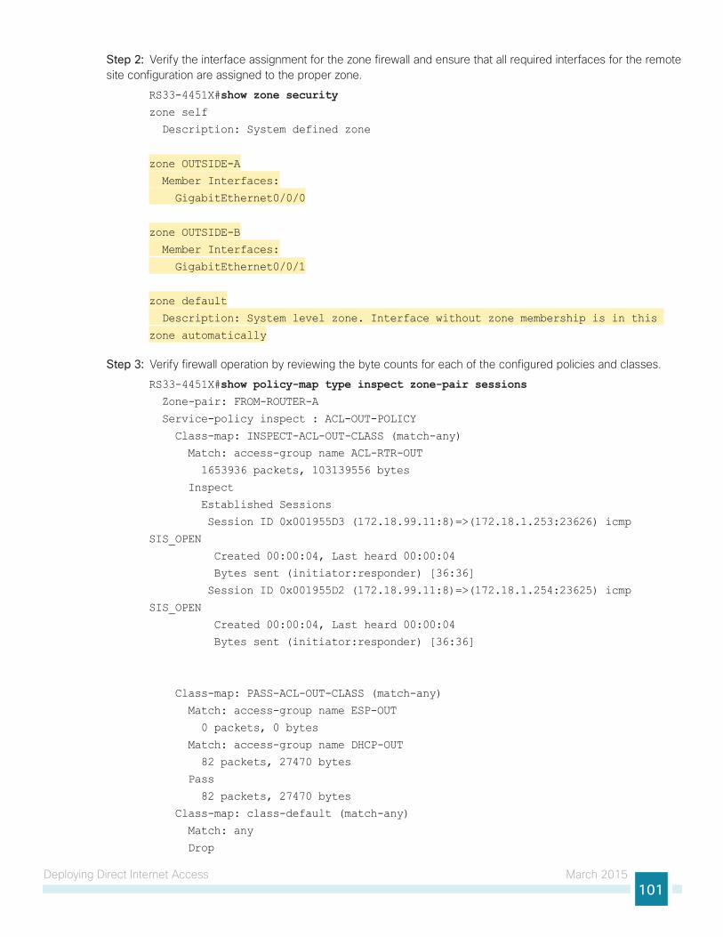
Deploying Direct Internet Access March 2015101
Step 2: Verify the interface assignment for the zone firewall and ensure that all required interfaces for the remote site configuration are assigned to the proper zone.
RS33-4451X#show zone securityzone self
Description: System defined zone
zone OUTSIDE-A
Member Interfaces:
GigabitEthernet0/0/0
zone OUTSIDE-B
Member Interfaces:
GigabitEthernet0/0/1
zone default
Description: System level zone. Interface without zone membership is in this
zone automatically
Step 3: Verify firewall operation by reviewing the byte counts for each of the configured policies and classes.
RS33-4451X#show policy-map type inspect zone-pair sessions Zone-pair: FROM-ROUTER-A
Service-policy inspect : ACL-OUT-POLICY
Class-map: INSPECT-ACL-OUT-CLASS (match-any)
Match: access-group name ACL-RTR-OUT
1653936 packets, 103139556 bytes
Inspect
Established Sessions
Session ID 0x001955D3 (172.18.99.11:8)=>(172.18.1.253:23626) icmp
SIS_OPEN
Created 00:00:04, Last heard 00:00:04
Bytes sent (initiator:responder) [36:36]
Session ID 0x001955D2 (172.18.99.11:8)=>(172.18.1.254:23625) icmp
SIS_OPEN
Created 00:00:04, Last heard 00:00:04
Bytes sent (initiator:responder) [36:36]
Class-map: PASS-ACL-OUT-CLASS (match-any)
Match: access-group name ESP-OUT
0 packets, 0 bytes
Match: access-group name DHCP-OUT
82 packets, 27470 bytes
Pass
82 packets, 27470 bytes
Class-map: class-default (match-any)
Match: any
Drop
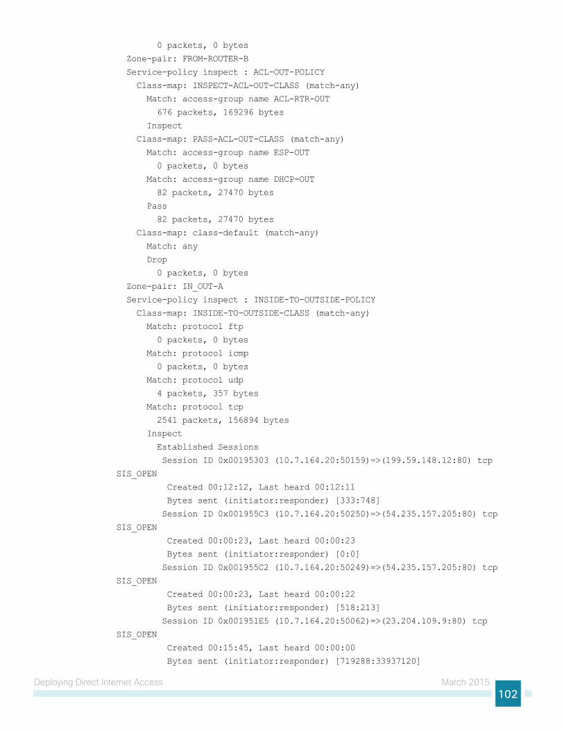
Deploying Direct Internet Access March 2015102
0 packets, 0 bytes
Zone-pair: FROM-ROUTER-B
Service-policy inspect : ACL-OUT-POLICY
Class-map: INSPECT-ACL-OUT-CLASS (match-any)
Match: access-group name ACL-RTR-OUT
676 packets, 169296 bytes
Inspect
Class-map: PASS-ACL-OUT-CLASS (match-any)
Match: access-group name ESP-OUT
0 packets, 0 bytes
Match: access-group name DHCP-OUT
82 packets, 27470 bytes
Pass
82 packets, 27470 bytes
Class-map: class-default (match-any)
Match: any
Drop
0 packets, 0 bytes
Zone-pair: IN_OUT-A
Service-policy inspect : INSIDE-TO-OUTSIDE-POLICY
Class-map: INSIDE-TO-OUTSIDE-CLASS (match-any)
Match: protocol ftp
0 packets, 0 bytes
Match: protocol icmp
0 packets, 0 bytes
Match: protocol udp
4 packets, 357 bytes
Match: protocol tcp
2541 packets, 156894 bytes
Inspect
Established Sessions
Session ID 0x00195303 (10.7.164.20:50159)=>(199.59.148.12:80) tcp
SIS_OPEN
Created 00:12:12, Last heard 00:12:11
Bytes sent (initiator:responder) [333:748]
Session ID 0x001955C3 (10.7.164.20:50250)=>(54.235.157.205:80) tcp
SIS_OPEN
Created 00:00:23, Last heard 00:00:23
Bytes sent (initiator:responder) [0:0]
Session ID 0x001955C2 (10.7.164.20:50249)=>(54.235.157.205:80) tcp
SIS_OPEN
Created 00:00:23, Last heard 00:00:22
Bytes sent (initiator:responder) [518:213]
Session ID 0x001951E5 (10.7.164.20:50062)=>(23.204.109.9:80) tcp
SIS_OPEN
Created 00:15:45, Last heard 00:00:00
Bytes sent (initiator:responder) [719288:33937120]
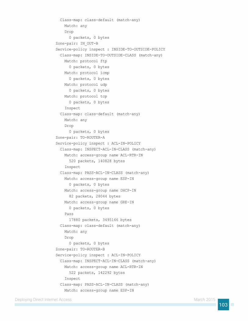
Deploying Direct Internet Access March 2015103
Class-map: class-default (match-any)
Match: any
Drop
0 packets, 0 bytes
Zone-pair: IN_OUT-B
Service-policy inspect : INSIDE-TO-OUTSIDE-POLICY
Class-map: INSIDE-TO-OUTSIDE-CLASS (match-any)
Match: protocol ftp
0 packets, 0 bytes
Match: protocol icmp
0 packets, 0 bytes
Match: protocol udp
0 packets, 0 bytes
Match: protocol tcp
0 packets, 0 bytes
Inspect
Class-map: class-default (match-any)
Match: any
Drop
0 packets, 0 bytes
Zone-pair: TO-ROUTER-A
Service-policy inspect : ACL-IN-POLICY
Class-map: INSPECT-ACL-IN-CLASS (match-any)
Match: access-group name ACL-RTR-IN
520 packets, 140828 bytes
Inspect
Class-map: PASS-ACL-IN-CLASS (match-any)
Match: access-group name ESP-IN
0 packets, 0 bytes
Match: access-group name DHCP-IN
82 packets, 28044 bytes
Match: access-group name GRE-IN
0 packets, 0 bytes
Pass
17880 packets, 3495146 bytes
Class-map: class-default (match-any)
Match: any
Drop
0 packets, 0 bytes
Zone-pair: TO-ROUTER-B
Service-policy inspect : ACL-IN-POLICY
Class-map: INSPECT-ACL-IN-CLASS (match-any)
Match: access-group name ACL-RTR-IN
522 packets, 142292 bytes
Inspect
Class-map: PASS-ACL-IN-CLASS (match-any)
Match: access-group name ESP-IN
Deploying Direct Internet Access March 2015104
0 packets, 0 bytes
Match: access-group name DHCP-IN
82 packets, 28044 bytes
Match: access-group name GRE-IN
0 packets, 0 bytes
Pass
17888 packets, 3496154 bytes
Class-map: class-default (match-any)
Match: any
Drop
0 packets, 0 bytes
Step 4: Add the following command to the router configuration in order to identify traffic dropped by the Cisco IOS-XE zone firewall.
parameter-map type inspect global
log dropped-packets
In IOS, when you configure the command ip inspect drop-pkt, the following is automatically added to the router configuration:
parameter-map type inspect global
log dropped-packets enable
Tech Tip
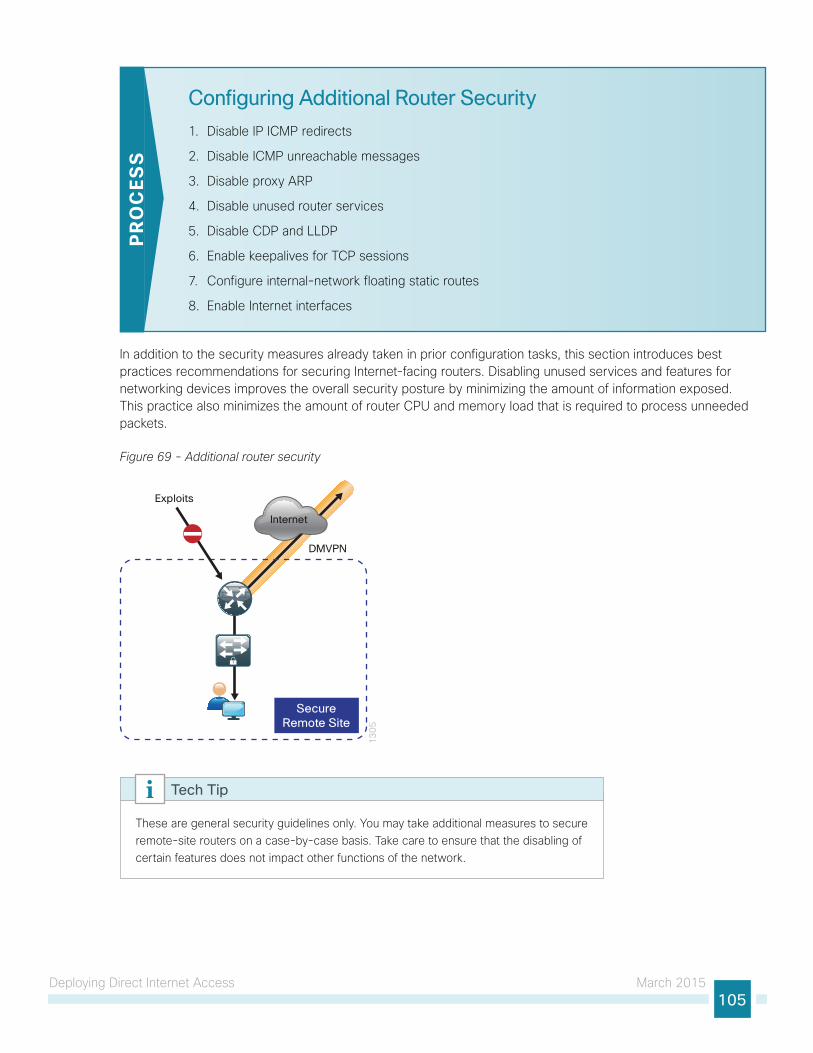
Deploying Direct Internet Access March 2015105
Configuring Additional Router Security
1. Disable IP ICMP redirects
2. Disable ICMP unreachable messages
3. Disable proxy ARP
4. Disable unused router services
5. Disable CDP and LLDP
6. Enable keepalives for TCP sessions
7. Configure internal-network floating static routes
8. Enable Internet interfaces
PR
OC
ESS
In addition to the security measures already taken in prior configuration tasks, this section introduces best practices recommendations for securing Internet-facing routers. Disabling unused services and features for networking devices improves the overall security posture by minimizing the amount of information exposed. This practice also minimizes the amount of router CPU and memory load that is required to process unneeded packets.
Figure 69 - Additional router security
13
05
Internet
SecureRemote Site
DMVPN
Exploits
These are general security guidelines only. You may take additional measures to secure remote-site routers on a case-by-case basis. Take care to ensure that the disabling of certain features does not impact other functions of the network.
Tech Tip
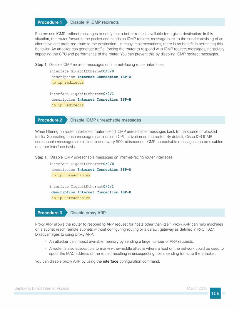
Deploying Direct Internet Access March 2015106
Procedure 1 Disable IP ICMP redirects
Routers use ICMP redirect messages to notify that a better route is available for a given destination. In this situation, the router forwards the packet and sends an ICMP redirect message back to the sender advising of an alternative and preferred route to the destination. In many implementations, there is no benefit in permitting this behavior. An attacker can generate traffic, forcing the router to respond with ICMP redirect messages, negatively impacting the CPU and performance of the router. You can prevent this by disabling ICMP redirect messages.
Step 1: Disable ICMP redirect messages on Internet-facing router interfaces.
interface GigabitEthernet0/0/0 description Internet Connection ISP-A no ip redirects
interface GigabitEthernet0/0/1 description Internet Connection ISP-B no ip redirects
Procedure 2 Disable ICMP unreachable messages
When filtering on router interfaces, routers send ICMP unreachable messages back to the source of blocked traffic. Generating these messages can increase CPU utilization on the router. By default, Cisco IOS ICMP unreachable messages are limited to one every 500 milliseconds. ICMP unreachable messages can be disabled on a per interface basis.
Step 1: Disable ICMP unreachable messages on Internet-facing router interfaces.
interface GigabitEthernet0/0/0 description Internet Connection ISP-A no ip unreachables
interface GigabitEthernet0/0/1 description Internet Connection ISP-B no ip unreachables
Procedure 3 Disable proxy ARP
Proxy ARP allows the router to respond to ARP request for hosts other than itself. Proxy ARP can help machines on a subnet reach remote subnets without configuring routing or a default gateway as defined in RFC 1027. Disadvantages to using proxy ARP:
• An attacker can impact available memory by sending a large number of ARP requests.
• A router is also susceptible to man-in-the-middle attacks where a host on the network could be used to spoof the MAC address of the router, resulting in unsuspecting hosts sending traffic to the attacker.
You can disable proxy ARP by using the interface configuration command.
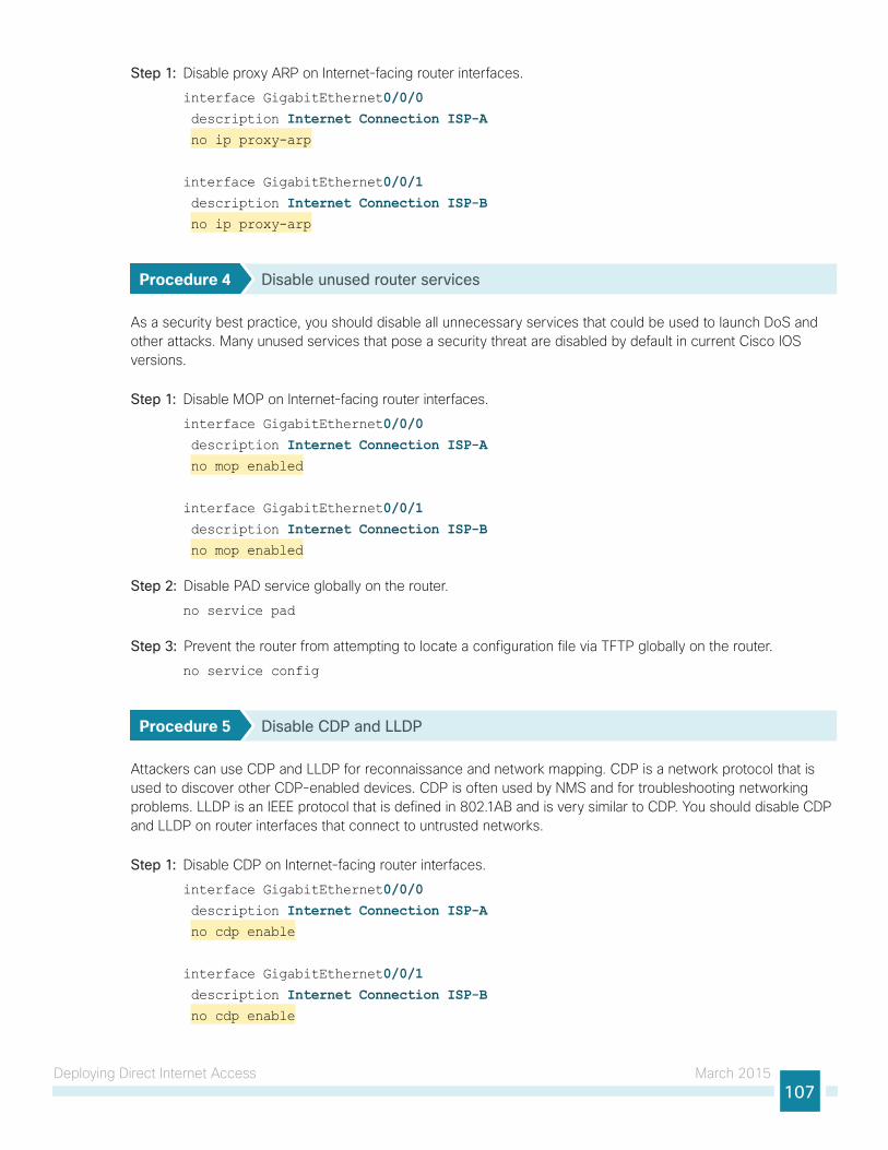
Deploying Direct Internet Access March 2015107
Step 1: Disable proxy ARP on Internet-facing router interfaces.
interface GigabitEthernet0/0/0 description Internet Connection ISP-A no ip proxy-arp
interface GigabitEthernet0/0/1 description Internet Connection ISP-B no ip proxy-arp
Procedure 4 Disable unused router services
As a security best practice, you should disable all unnecessary services that could be used to launch DoS and other attacks. Many unused services that pose a security threat are disabled by default in current Cisco IOS versions.
Step 1: Disable MOP on Internet-facing router interfaces.
interface GigabitEthernet0/0/0 description Internet Connection ISP-A no mop enabled
interface GigabitEthernet0/0/1 description Internet Connection ISP-B no mop enabled
Step 2: Disable PAD service globally on the router.
no service pad
Step 3: Prevent the router from attempting to locate a configuration file via TFTP globally on the router.
no service config
Procedure 5 Disable CDP and LLDP
Attackers can use CDP and LLDP for reconnaissance and network mapping. CDP is a network protocol that is used to discover other CDP-enabled devices. CDP is often used by NMS and for troubleshooting networking problems. LLDP is an IEEE protocol that is defined in 802.1AB and is very similar to CDP. You should disable CDP and LLDP on router interfaces that connect to untrusted networks.
Step 1: Disable CDP on Internet-facing router interfaces.
interface GigabitEthernet0/0/0 description Internet Connection ISP-A no cdp enable
interface GigabitEthernet0/0/1 description Internet Connection ISP-B no cdp enable
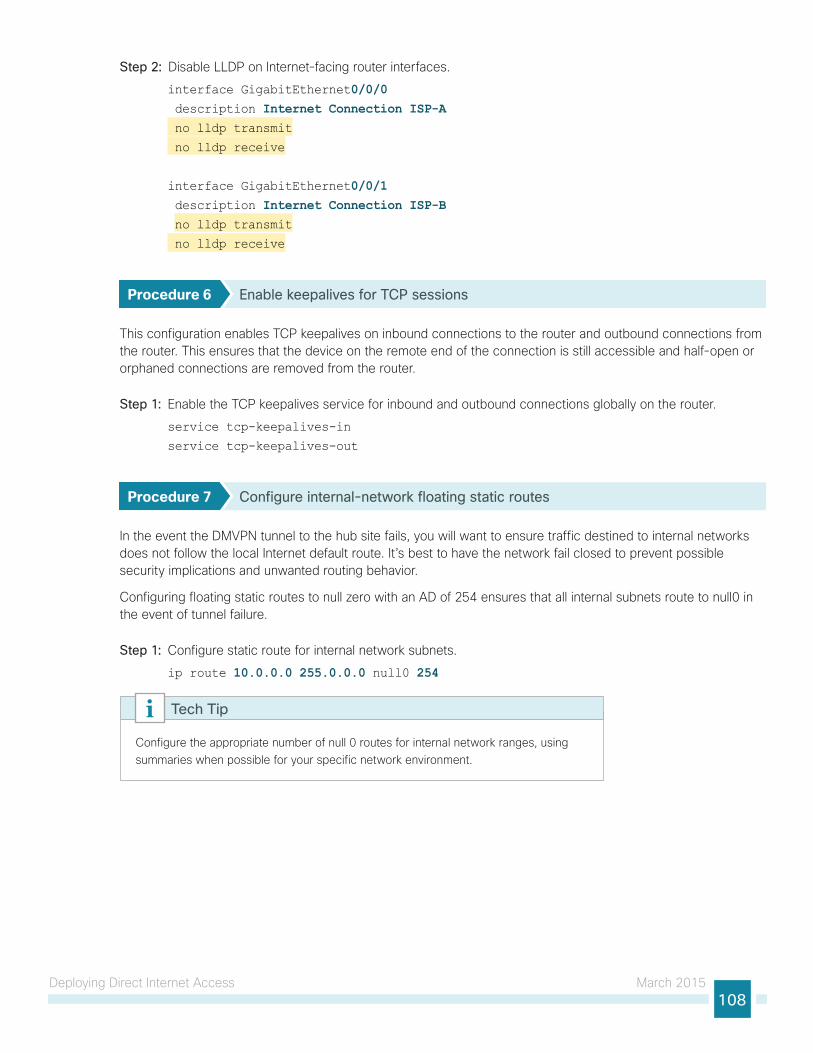
Deploying Direct Internet Access March 2015108
Step 2: Disable LLDP on Internet-facing router interfaces.
interface GigabitEthernet0/0/0 description Internet Connection ISP-A no lldp transmit
no lldp receive
interface GigabitEthernet0/0/1 description Internet Connection ISP-B no lldp transmit
no lldp receive
Procedure 6 Enable keepalives for TCP sessions
This configuration enables TCP keepalives on inbound connections to the router and outbound connections from the router. This ensures that the device on the remote end of the connection is still accessible and half-open or orphaned connections are removed from the router.
Step 1: Enable the TCP keepalives service for inbound and outbound connections globally on the router.
service tcp-keepalives-in
service tcp-keepalives-out
Procedure 7 Configure internal-network floating static routes
In the event the DMVPN tunnel to the hub site fails, you will want to ensure traffic destined to internal networks does not follow the local Internet default route. It’s best to have the network fail closed to prevent possible security implications and unwanted routing behavior.
Configuring floating static routes to null zero with an AD of 254 ensures that all internal subnets route to null0 in the event of tunnel failure.
Step 1: Configure static route for internal network subnets.
ip route 10.0.0.0 255.0.0.0 null0 254
Configure the appropriate number of null 0 routes for internal network ranges, using summaries when possible for your specific network environment.
Tech Tip
Deploying Direct Internet Access March 2015109
Procedure 8 Enable Internet interfaces
Now that the security configurations are complete, you can enable the Internet-facing interfaces.
Step 1: Enable the Internet-facing router interfaces.
interface GigabitEthernet0/0/0 description Internet Connection ISP-A no shutdown
interface GigabitEthernet0/0/1 description Internet Connection ISP-B no shutdown
Configuring ISP Black-Hole Routing Detection
1. Configure ISP black-hole routing detection
PR
OC
ESS
In many cases you will need to ensure connectivity issues with your ISP does not cause black-hole routing conditions. Failure conditions can exist where the DHCP address and routes are not removed from the remote-site router when connectivity issues exist with the broadband service or local premise equipment. There may also be circumstances if certain services are unreachable within via the local ISP connection that you want to reroute to a secondary Internet service.
If Internet fallback is required, configure one or more of the following options.
Procedure 1 Configure ISP black-hole routing detection
Option 1: DMVPN Tunnel State TrackingIn this solution, the DMVPN tunnel state is used to monitor the status of the ISP connection used as the primary path for local Internet traffic. In this example, a “down” state of the tunnel interface triggers the removal of the default route via an EEM script. If tunnel state is “up” the route will remain.
With this method, a failure or maintenance at the central site can cause a failover event where the route is removed due to tunnel state change and the local Internet connection remains active at the remote site.
Tech Tip
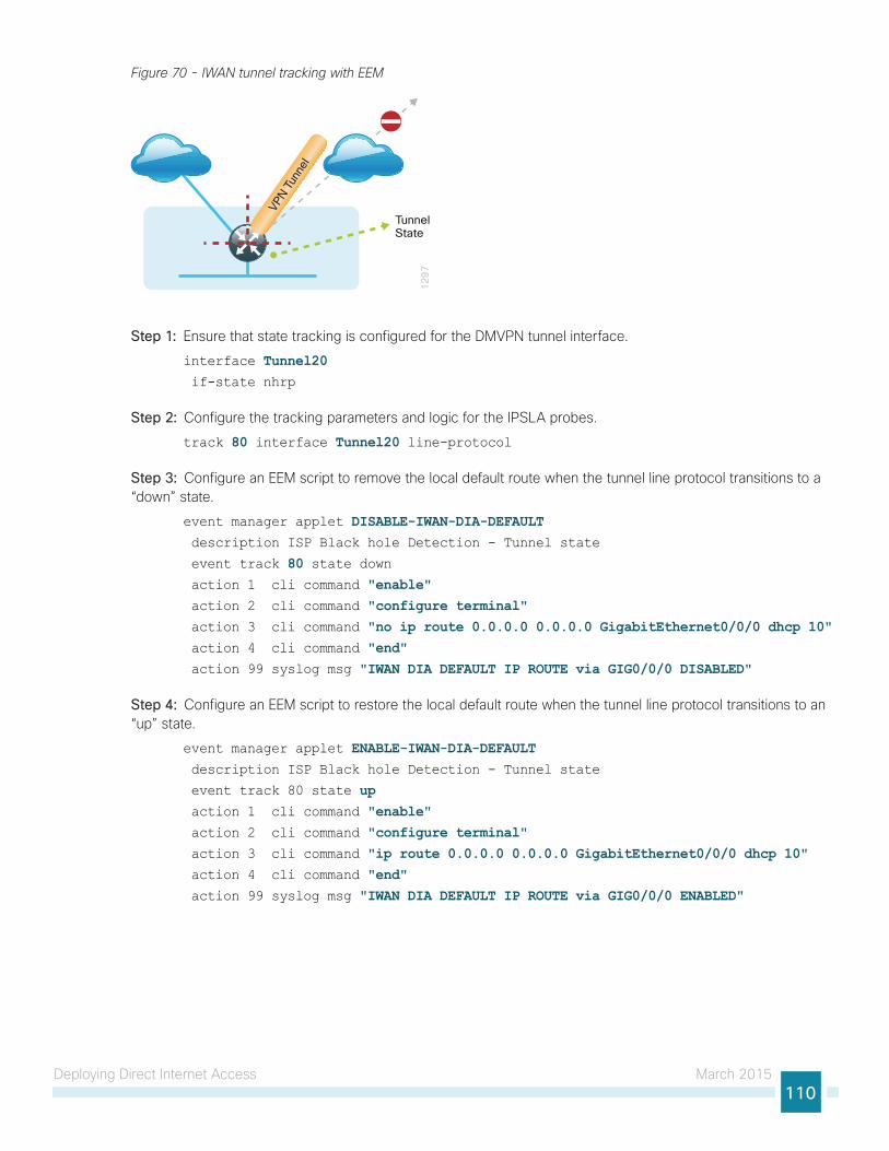
Deploying Direct Internet Access March 2015110
Figure 70 - IWAN tunnel tracking with EEM
12
97
VPN T
unne
l
TunnelState
Step 1: Ensure that state tracking is configured for the DMVPN tunnel interface.
interface Tunnel20 if-state nhrp
Step 2: Configure the tracking parameters and logic for the IPSLA probes.
track 80 interface Tunnel20 line-protocol
Step 3: Configure an EEM script to remove the local default route when the tunnel line protocol transitions to a “down” state.
event manager applet DISABLE-IWAN-DIA-DEFAULT description ISP Black hole Detection - Tunnel state
event track 80 state down action 1 cli command "enable" action 2 cli command "configure terminal" action 3 cli command "no ip route 0.0.0.0 0.0.0.0 GigabitEthernet0/0/0 dhcp 10" action 4 cli command "end" action 99 syslog msg "IWAN DIA DEFAULT IP ROUTE via GIG0/0/0 DISABLED"
Step 4: Configure an EEM script to restore the local default route when the tunnel line protocol transitions to an “up” state.
event manager applet ENABLE-IWAN-DIA-DEFAULT description ISP Black hole Detection - Tunnel state
event track 80 state up action 1 cli command "enable" action 2 cli command "configure terminal" action 3 cli command "ip route 0.0.0.0 0.0.0.0 GigabitEthernet0/0/0 dhcp 10" action 4 cli command "end" action 99 syslog msg "IWAN DIA DEFAULT IP ROUTE via GIG0/0/0 ENABLED"
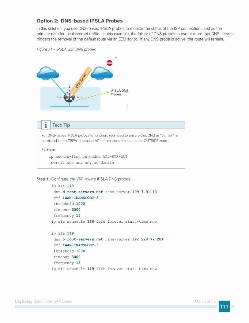
Deploying Direct Internet Access March 2015111
Option 2: DNS-based IPSLA ProbesIn this solution, you use DNS-based IPSLA probes to monitor the status of the ISP connection used as the primary path for local Internet traffic. In this example, the failure of DNS probes to two or more root DNS servers triggers the removal of the default route via an EEM script. If any DNS probe is active, the route will remain.
Figure 71 - IPSLA with DNS probes
12
99
VPN T
unne
l
IP SLA DNSProbes
For DNS-based IPSLA probes to function, you need to ensure that DNS or “domain” is permitted in the ZBFW outbound ACL, from the self-zone to the OUTSIDE zone.
Example:
ip access-list extended ACL-RTR-OUT
permit udp any any eq domain
Tech Tip
Step 1: Configure the VRF-aware IPSLA DNS probes.
ip sla 118 dns d.root-servers.net name-server 199.7.91.13 vrf IWAN-TRANSPORT-3 threshold 1000 timeout 3000 frequency 15ip sla schedule 118 life forever start-time now
ip sla 119 dns b.root-servers.net name-server 192.228.79.201 vrf IWAN-TRANSPORT-3 threshold 1000 timeout 3000 frequency 15ip sla schedule 119 life forever start-time now
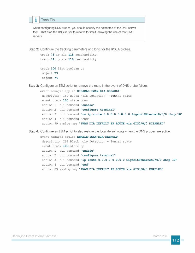
Deploying Direct Internet Access March 2015112
When configuring DNS probes, you should specify the hostname of the DNS server itself. That asks the DNS server to resolve for itself, allowing the use of root DNS servers.
Tech Tip
Step 2: Configure the tracking parameters and logic for the IPSLA probes.
track 73 ip sla 118 reachabilitytrack 74 ip sla 119 reachability!
track 100 list boolean or object 73 object 74
Step 3: Configure an EEM script to remove the route in the event of DNS probe failure.
event manager applet DISABLE-IWAN-DIA-DEFAULT description ISP Black hole Detection - Tunnel state
event track 100 state down action 1 cli command "enable" action 2 cli command "configure terminal" action 3 cli command "no ip route 0.0.0.0 0.0.0.0 GigabitEthernet0/0/0 dhcp 10" action 4 cli command "end"
action 99 syslog msg "IWAN DIA DEFAULT IP ROUTE via GIG0/0/0 DISABLED"
Step 4: Configure an EEM script to also restore the local default route when the DNS probes are active.
event manager applet ENABLE-IWAN-DIA-DEFAULT description ISP Black hole Detection - Tunnel state
event track 100 state up action 1 cli command "enable" action 2 cli command "configure terminal" action 3 cli command "ip route 0.0.0.0 0.0.0.0 GigabitEthernet0/0/0 dhcp 10" action 4 cli command "end" action 99 syslog msg "IWAN DIA DEFAULT IP ROUTE via GIG0/0/0 ENABLED"

Deploying Direct Internet Access March 2015113
Option 3: IPSLA ICMP ProbesIn this solution, you use IPSLA ICMP probes to monitor the status of the ISP connection used as the primary path for local Internet traffic. In this example, the failure of ICMP probes to two different IP hosts triggers the removal of the default route via an EEM script. If either ICMP probe is active, the route will remain.
Figure 72 - IPSLA with ICMP probes
12
98
VPN T
unne
l
IP SLAProbes
For ICMP-based IPSLA probes to function, you need to ensure ICMP is permitted in the outbound ACL, from the self-zone to the OUTSIDE zone.
Tech Tip
Step 1: Configure the VRF-aware IPSLA ICMP probes.
ip sla 110 icmp-echo 172.18.1.253 source-interface GigabitEthernet0/0/0 vrf IWAN-TRANSPORT-3 threshold 1000 frequency 15ip sla schedule 110 life forever start-time now
ip sla 111
icmp-echo 172.18.1.254 source-interface GigabitEthernet0/0/0 vrf IWAN-TRANSPORT-3 threshold 1000 frequency 15ip sla schedule 111 life forever start-time now
Step 2: Configure the tracking parameters and logic for the IPSLA ICMP probes.
track 60 ip sla 110 reachabilitytrack 61 ip sla 111 reachabilitytrack 62 list boolean or object 60 object 61
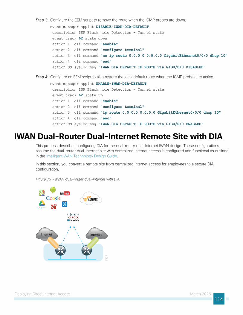
Deploying Direct Internet Access March 2015114
Step 3: Configure the EEM script to remove the route when the ICMP probes are down.
event manager applet DISABLE-IWAN-DIA-DEFAULT description ISP Black hole Detection - Tunnel state
event track 62 state down action 1 cli command "enable" action 2 cli command "configure terminal" action 3 cli command "no ip route 0.0.0.0 0.0.0.0 GigabitEthernet0/0/0 dhcp 10" action 4 cli command "end" action 99 syslog msg "IWAN DIA DEFAULT IP ROUTE via GIG0/0/0 DISABLED"
Step 4: Configure an EEM script to also restore the local default route when the ICMP probes are active.
event manager applet ENABLE-IWAN-DIA-DEFAULT description ISP Black hole Detection - Tunnel state
event track 62 state up action 1 cli command "enable" action 2 cli command "configure terminal" action 3 cli command "ip route 0.0.0.0 0.0.0.0 GigabitEthernet0/0/0 dhcp 10" action 4 cli command "end" action 99 syslog msg "IWAN DIA DEFAULT IP ROUTE via GIG0/0/0 ENABLED"
IWAN Dual-Router Dual-Internet Remote Site with DIAThis process describes configuring DIA for the dual-router dual-Internet IWAN design. These configurations assume the dual-router dual-Internet site with centralized Internet access is configured and functional as outlined in the Intelligent WAN Technology Design Guide.
In this section, you convert a remote site from centralized Internet access for employees to a secure DIA configuration.
Figure 73 - IWAN dual-router dual-Internet with DIA
13
27
Internet Internet
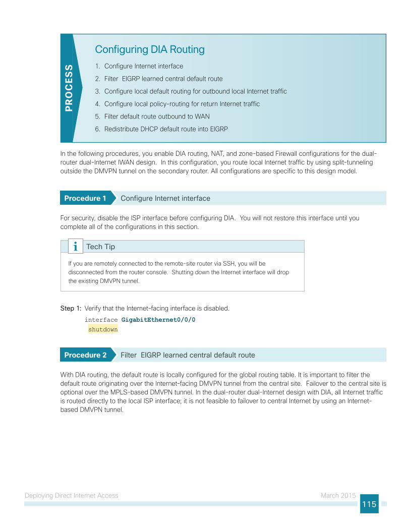
Deploying Direct Internet Access March 2015115
Configuring DIA Routing
1. Configure Internet interface
2. Filter EIGRP learned central default route
3. Configure local default routing for outbound local Internet traffic
4. Configure local policy-routing for return Internet traffic
5. Filter default route outbound to WAN
6. Redistribute DHCP default route into EIGRP
PR
OC
ESS
In the following procedures, you enable DIA routing, NAT, and zone-based Firewall configurations for the dual-router dual-Internet IWAN design. In this configuration, you route local Internet traffic by using split-tunneling outside the DMVPN tunnel on the secondary router. All configurations are specific to this design model.
Procedure 1 Configure Internet interface
For security, disable the ISP interface before configuring DIA. You will not restore this interface until you complete all of the configurations in this section.
If you are remotely connected to the remote-site router via SSH, you will be disconnected from the router console. Shutting down the Internet interface will drop the existing DMVPN tunnel.
Tech Tip
Step 1: Verify that the Internet-facing interface is disabled.
interface GigabitEthernet0/0/0 shutdown
Procedure 2 Filter EIGRP learned central default route
With DIA routing, the default route is locally configured for the global routing table. It is important to filter the default route originating over the Internet-facing DMVPN tunnel from the central site. Failover to the central site is optional over the MPLS-based DMVPN tunnel. In the dual-router dual-Internet design with DIA, all Internet traffic is routed directly to the local ISP interface; it is not feasible to failover to central Internet by using an Internet-based DMVPN tunnel.
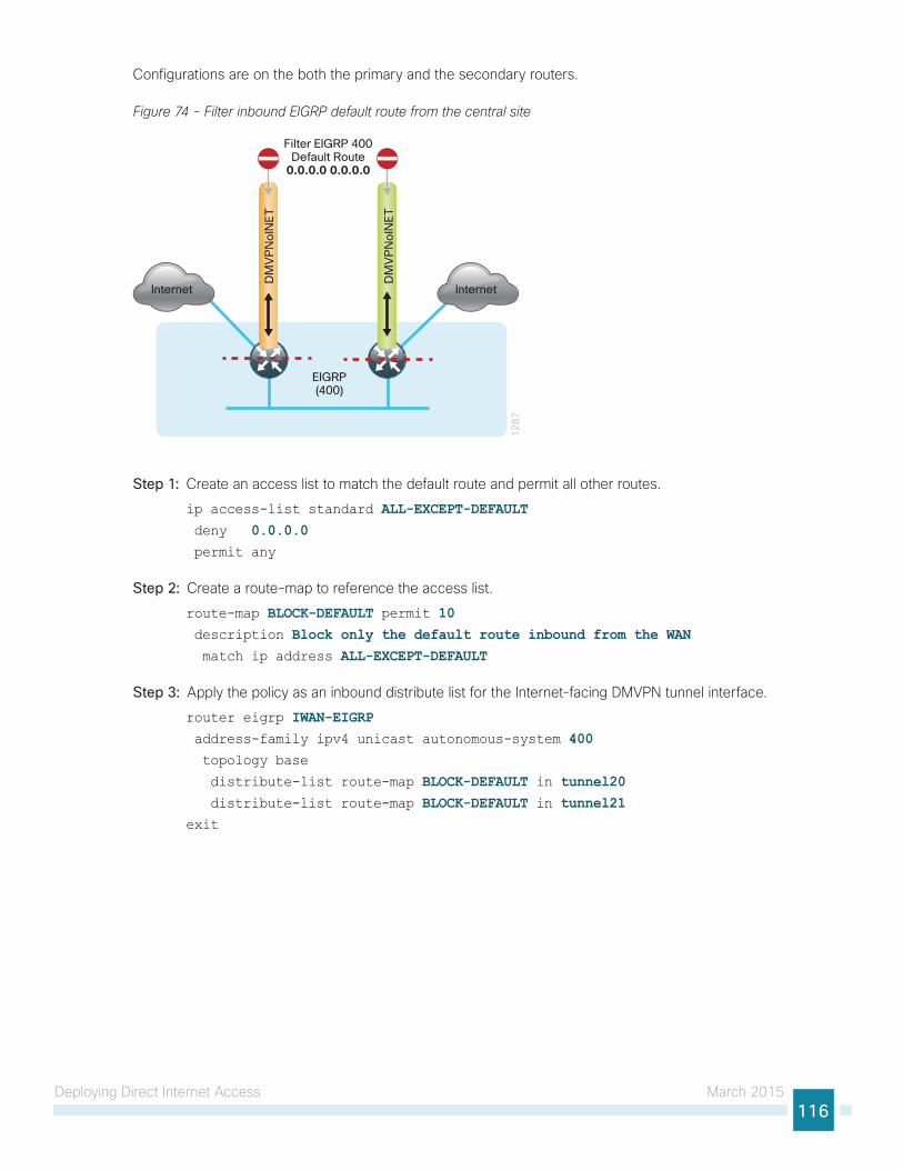
Deploying Direct Internet Access March 2015116
Configurations are on the both the primary and the secondary routers.
Figure 74 - Filter inbound EIGRP default route from the central site
12
87
Internet
DM
VP
No
INE
T
DM
VP
No
INE
T
EIGRP(400)
Filter EIGRP 400Default Route
0.0.0.0 0.0.0.0
Internet
Step 1: Create an access list to match the default route and permit all other routes.
ip access-list standard ALL-EXCEPT-DEFAULT deny 0.0.0.0 permit any
Step 2: Create a route-map to reference the access list.
route-map BLOCK-DEFAULT permit 10 description Block only the default route inbound from the WAN match ip address ALL-EXCEPT-DEFAULT
Step 3: Apply the policy as an inbound distribute list for the Internet-facing DMVPN tunnel interface.
router eigrp IWAN-EIGRP address-family ipv4 unicast autonomous-system 400 topology base
distribute-list route-map BLOCK-DEFAULT in tunnel20 distribute-list route-map BLOCK-DEFAULT in tunnel21exit
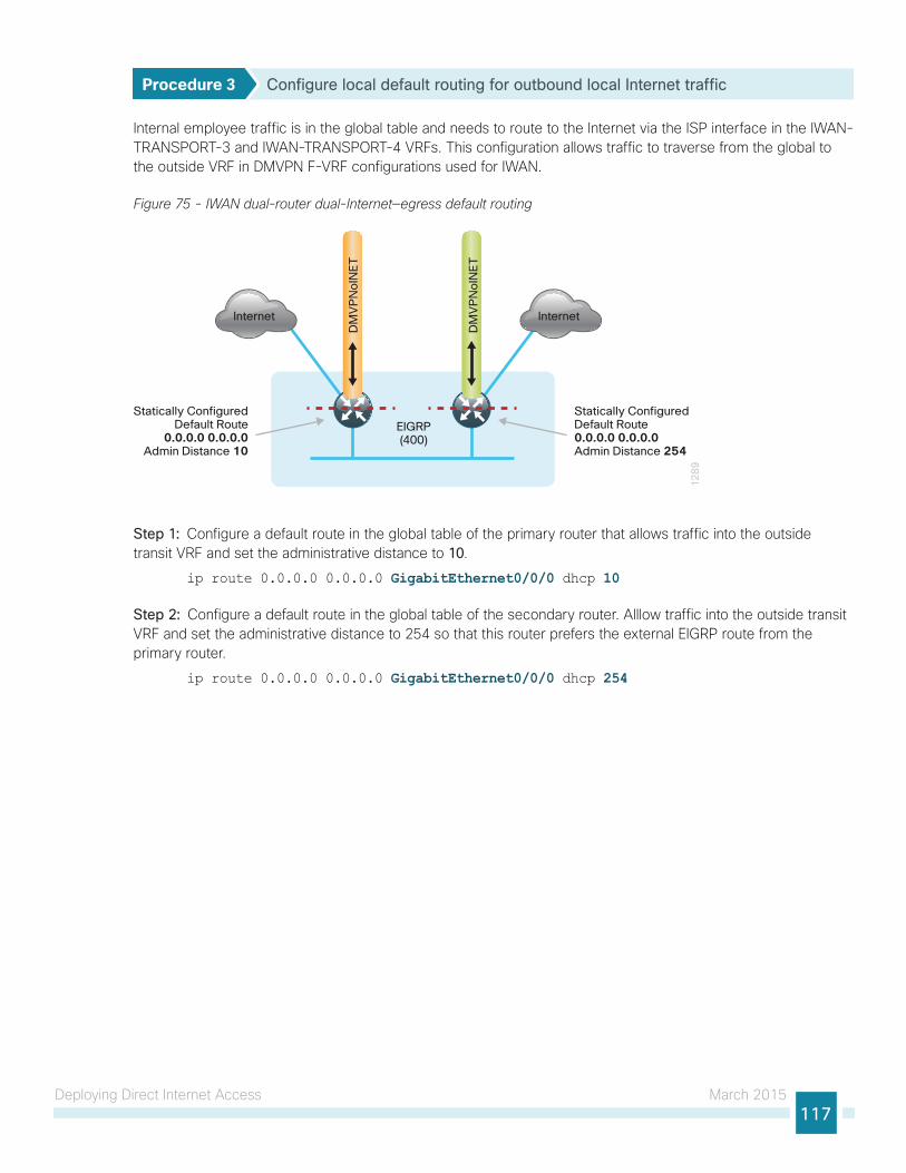
Deploying Direct Internet Access March 2015117
Procedure 3 Configure local default routing for outbound local Internet traffic
Internal employee traffic is in the global table and needs to route to the Internet via the ISP interface in the IWAN-TRANSPORT-3 and IWAN-TRANSPORT-4 VRFs. This configuration allows traffic to traverse from the global to the outside VRF in DMVPN F-VRF configurations used for IWAN.
Figure 75 - IWAN dual-router dual-Internet—egress default routing
12
89
Internet
DM
VP
No
INE
T
DM
VP
No
INE
T
EIGRP(400)
Internet
Statically ConfiguredDefault Route0.0.0.0 0.0.0.0Admin Distance 254
Statically ConfiguredDefault Route
0.0.0.0 0.0.0.0Admin Distance 10
Step 1: Configure a default route in the global table of the primary router that allows traffic into the outside transit VRF and set the administrative distance to 10.
ip route 0.0.0.0 0.0.0.0 GigabitEthernet0/0/0 dhcp 10
Step 2: Configure a default route in the global table of the secondary router. Alllow traffic into the outside transit VRF and set the administrative distance to 254 so that this router prefers the external EIGRP route from the primary router.
ip route 0.0.0.0 0.0.0.0 GigabitEthernet0/0/0 dhcp 254
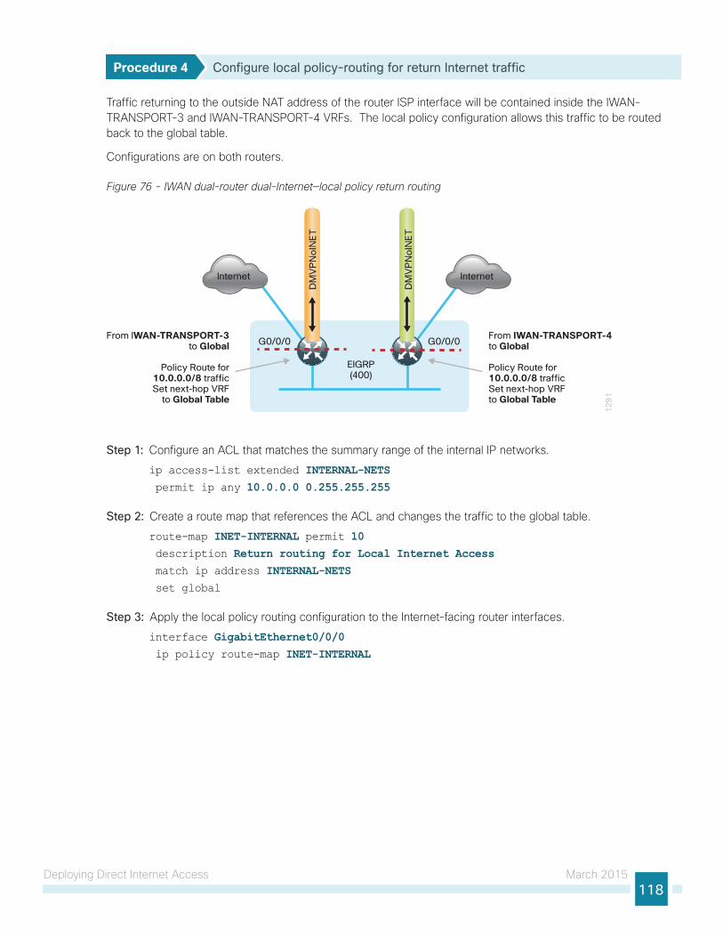
Deploying Direct Internet Access March 2015118
Procedure 4 Configure local policy-routing for return Internet traffic
Traffic returning to the outside NAT address of the router ISP interface will be contained inside the IWAN-TRANSPORT-3 and IWAN-TRANSPORT-4 VRFs. The local policy configuration allows this traffic to be routed back to the global table.
Configurations are on both routers.
Figure 76 - IWAN dual-router dual-Internet—local policy return routing
12
91
Internet
DM
VP
No
INE
T
DM
VP
No
INE
T
EIGRP(400)
Internet
From IWAN-TRANSPORT-4 to Global
Policy Route for 10.0.0.0/8 traffic Set next-hop VRF to Global Table
From IWAN-TRANSPORT-3to Global
Policy Route for10.0.0.0/8 trafficSet next-hop VRF
to Global Table
G0/0/0 G0/0/0
Step 1: Configure an ACL that matches the summary range of the internal IP networks.
ip access-list extended INTERNAL-NETS permit ip any 10.0.0.0 0.255.255.255
Step 2: Create a route map that references the ACL and changes the traffic to the global table.
route-map INET-INTERNAL permit 10 description Return routing for Local Internet Access match ip address INTERNAL-NETS set global
Step 3: Apply the local policy routing configuration to the Internet-facing router interfaces.
interface GigabitEthernet0/0/0 ip policy route-map INET-INTERNAL
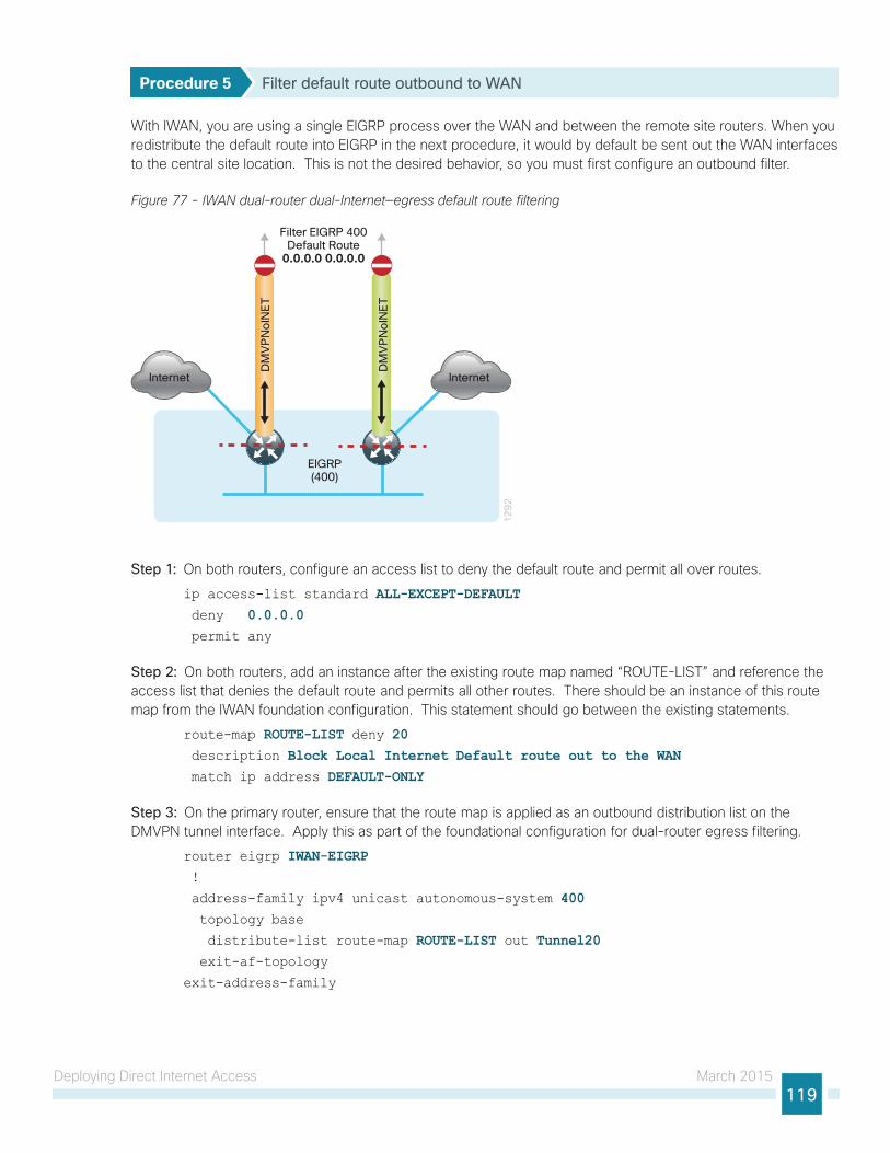
Deploying Direct Internet Access March 2015119
Procedure 5 Filter default route outbound to WAN
With IWAN, you are using a single EIGRP process over the WAN and between the remote site routers. When you redistribute the default route into EIGRP in the next procedure, it would by default be sent out the WAN interfaces to the central site location. This is not the desired behavior, so you must first configure an outbound filter.
Figure 77 - IWAN dual-router dual-Internet—egress default route filtering
12
92
InternetD
MV
PN
oIN
ET
DM
VP
No
INE
T
EIGRP(400)
Filter EIGRP 400Default Route
0.0.0.0 0.0.0.0
Internet
Step 1: On both routers, configure an access list to deny the default route and permit all over routes.
ip access-list standard ALL-EXCEPT-DEFAULT deny 0.0.0.0 permit any
Step 2: On both routers, add an instance after the existing route map named “ROUTE-LIST” and reference the access list that denies the default route and permits all other routes. There should be an instance of this route map from the IWAN foundation configuration. This statement should go between the existing statements.
route-map ROUTE-LIST deny 20 description Block Local Internet Default route out to the WAN match ip address DEFAULT-ONLY
Step 3: On the primary router, ensure that the route map is applied as an outbound distribution list on the DMVPN tunnel interface. Apply this as part of the foundational configuration for dual-router egress filtering.
router eigrp IWAN-EIGRP !
address-family ipv4 unicast autonomous-system 400 topology base
distribute-list route-map ROUTE-LIST out Tunnel20 exit-af-topology
exit-address-family
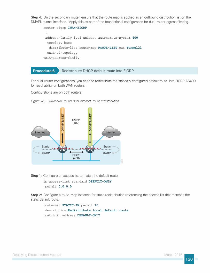
Deploying Direct Internet Access March 2015120
Step 4: On the secondary router, ensure that the route map is applied as an outbound distribution list on the DMVPN tunnel interface. Apply this as part of the foundational configuration for dual-router egress filtering.
router eigrp IWAN-EIGRP !
address-family ipv4 unicast autonomous-system 400 topology base
distribute-list route-map ROUTE-LIST out Tunnel21 exit-af-topology
exit-address-family
Procedure 6 Redistribute DHCP default route into EIGRP
For dual-router configurations, you need to redistribute the statically configured default route into EIGRP AS400 for reachability on both WAN routers.
Configurations are on both routers.
Figure 78 - IWAN dual-router dual-Internet—route redistribution
12
93
Internet
DM
VP
No
INE
T
DM
VP
No
INE
T
EIGRP(400)
Internet
Static
EIGRP
Static
EIGRP
EIGRP(400)
Step 1: Configure an access list to match the default route.
ip access-list standard DEFAULT-ONLY permit 0.0.0.0
Step 2: Configure a route-map instance for static redistribution referencing the access list that matches the static default route.
route-map STATIC-IN permit 10 description Redistribute local default route match ip address DEFAULT-ONLY
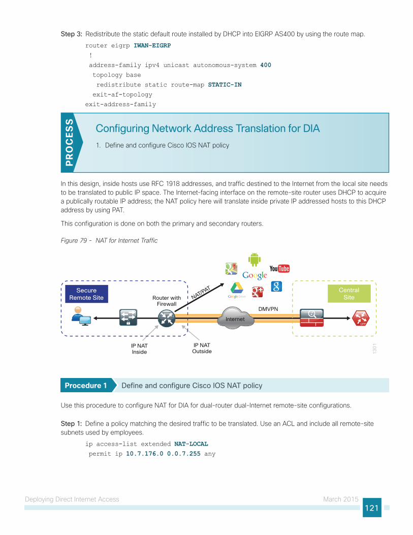
Deploying Direct Internet Access March 2015121
Step 3: Redistribute the static default route installed by DHCP into EIGRP AS400 by using the route map.
router eigrp IWAN-EIGRP !
address-family ipv4 unicast autonomous-system 400 topology base
redistribute static route-map STATIC-IN exit-af-topology
exit-address-family
Configuring Network Address Translation for DIA
1. Define and configure Cisco IOS NAT policy
PR
OC
ESS
In this design, inside hosts use RFC 1918 addresses, and traffic destined to the Internet from the local site needs to be translated to public IP space. The Internet-facing interface on the remote-site router uses DHCP to acquire a publically routable IP address; the NAT policy here will translate inside private IP addressed hosts to this DHCP address by using PAT.
This configuration is done on both the primary and secondary routers.
Figure 79 - NAT for Internet Traffic
13
01
Internet
DMVPN
IP NATInside
Router withFirewall
IP NATOutside
CentralSite
SecureRemote Site NAT/PAT
Procedure 1 Define and configure Cisco IOS NAT policy
Use this procedure to configure NAT for DIA for dual-router dual-Internet remote-site configurations.
Step 1: Define a policy matching the desired traffic to be translated. Use an ACL and include all remote-site subnets used by employees.
ip access-list extended NAT-LOCAL permit ip 10.7.176.0 0.0.7.255 any
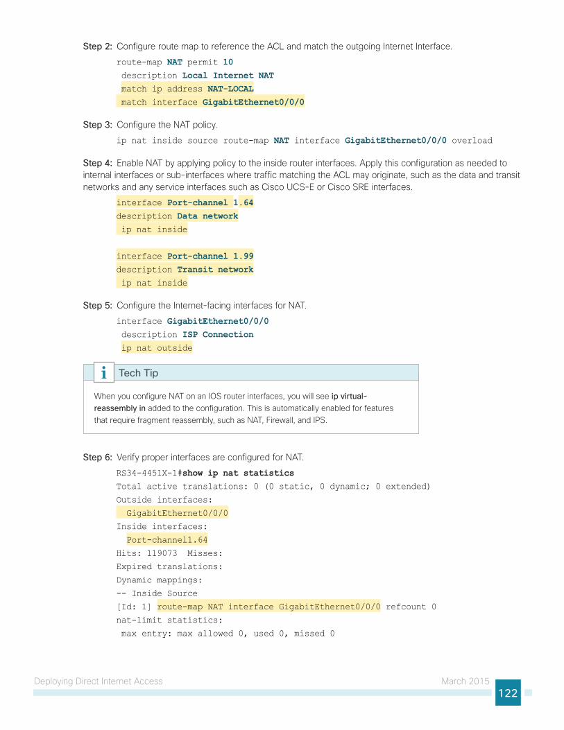
Deploying Direct Internet Access March 2015122
Step 2: Configure route map to reference the ACL and match the outgoing Internet Interface.
route-map NAT permit 10 description Local Internet NAT match ip address NAT-LOCAL match interface GigabitEthernet0/0/0
Step 3: Configure the NAT policy.
ip nat inside source route-map NAT interface GigabitEthernet0/0/0 overload
Step 4: Enable NAT by applying policy to the inside router interfaces. Apply this configuration as needed to internal interfaces or sub-interfaces where traffic matching the ACL may originate, such as the data and transit networks and any service interfaces such as Cisco UCS-E or Cisco SRE interfaces.
interface Port-channel 1.64description Data network ip nat inside
interface Port-channel 1.99description Transit network ip nat inside
Step 5: Configure the Internet-facing interfaces for NAT.
interface GigabitEthernet0/0/0 description ISP Connection ip nat outside
When you configure NAT on an IOS router interfaces, you will see ip virtual-reassembly in added to the configuration. This is automatically enabled for features that require fragment reassembly, such as NAT, Firewall, and IPS.
Tech Tip
Step 6: Verify proper interfaces are configured for NAT.
RS34-4451X-1#show ip nat statistics Total active translations: 0 (0 static, 0 dynamic; 0 extended)
Outside interfaces:
GigabitEthernet0/0/0
Inside interfaces:
Port-channel1.64
Hits: 119073 Misses:
Expired translations:
Dynamic mappings:
-- Inside Source
[Id: 1] route-map NAT interface GigabitEthernet0/0/0 refcount 0
nat-limit statistics:
max entry: max allowed 0, used 0, missed 0
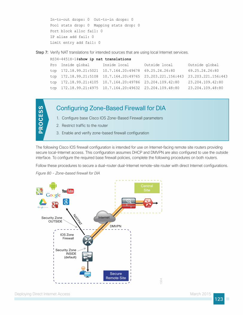
Deploying Direct Internet Access March 2015123
In-to-out drops: 0 Out-to-in drops: 0
Pool stats drop: 0 Mapping stats drop: 0
Port block alloc fail: 0
IP alias add fail: 0
Limit entry add fail: 0
Step 7: Verify NAT translations for intended sources that are using local Internet services.
RS34-4451X-1#show ip nat translations Pro Inside global Inside local Outside local Outside global
tcp 172.18.99.21:5021 10.7.164.20:49678 69.25.24.26:80 69.25.24.26:80
tcp 172.18.99.21:5108 10.7.164.20:49765 23.203.221.156:443 23.203.221.156:443
tcp 172.18.99.21:4105 10.7.164.20:49786 23.204.109.42:80 23.204.109.42:80
tcp 172.18.99.21:4975 10.7.164.20:49632 23.204.109.48:80 23.204.109.48:80
Configuring Zone-Based Firewall for DIA
1. Configure base Cisco IOS Zone-Based Firewall parameters
2. Restrict traffic to the router
3. Enable and verify zone-based firewall configurationPR
OC
ESS
The following Cisco IOS firewall configuration is intended for use on Internet-facing remote site routers providing secure local-Internet access. This configuration assumes DHCP and DMVPN are also configured to use the outside interface. To configure the required base firewall policies, complete the following procedures on both routers.
Follow these procedures to secure a dual-router dual-Internet remote-site router with direct Internet configurations.
Figure 80 - Zone-based firewall for DIA
13
04
Internet
CentralSite
SecureRemote Site
IOS ZoneFirewall
DMVPN
Security ZoneOUTSIDE
Security ZoneINSIDE
(default)
NAT/PAT

Deploying Direct Internet Access March 2015124
Procedure 1 Configure base Cisco IOS Zone-Based Firewall parameters
Step 1: If it is configured, remove the inbound ACL from the Internet-facing router interfaces, and then shut down the interface before continuing. This prevents unauthorized traffic while the ZBFW is configured.
interface GigabitEthernet0/0/0 shutdown
no ip access-list extended ACL-INET-PUBLIC
Step 2: Define security zones. A zone is a named group of interfaces that have similar functions or security requirements. This example defines the names of the two basic security zones identified. For simplicity, this design uses the “default” security zone for inside interfaces. Once the default zone has been defined, all interfaces not explicitly configured as members of a security zone will automatically be part of the default security zone.
zone security defaultzone security OUTSIDE
This design uses the “default” zone for all inside interfaces; traffic can flow between all interfaces in the default zone.
An interface not defined as part of a security zone is automatically part of the “default” zone. In this configuration, all undefined interface DMVPN tunnels, transit sub-interfaces, and service interfaces such as Cisco UCS-E, and SRE interfaces are included as part of the default zone.
Be aware that any interface that is removed from a defined security zone will be automatically placed into the default zone. In this configuration, that interface will be treated as an “inside” zone and have access to the internal routing domain..
Tech Tip
Step 3: Define a class map to match specific protocols. Class-maps apply match-any or match-all operators in order to determine how to apply the match criteria to the class. If match-any is specified, traffic must meet at least one of the match criteria in the class-map to be included in the class. If match-all is specified, traffic must meet all of the match criteria to be included in the class.
class-map type inspect match-any INSIDE-TO-OUTSIDE-CLASS match protocol ftp match protocol tcp match protocol udp match protocol icmp
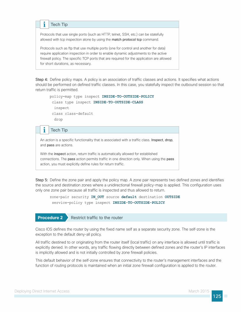
Deploying Direct Internet Access March 2015125
Protocols that use single ports (such as HTTP, telnet, SSH, etc.) can be statefully allowed with tcp inspection alone by using the match protocol tcp command.
Protocols such as ftp that use multiple ports (one for control and another for data) require application inspection in order to enable dynamic adjustments to the active firewall policy. The specific TCP ports that are required for the application are allowed for short durations, as necessary.
Tech Tip
Step 4: Define policy maps. A policy is an association of traffic classes and actions. It specifies what actions should be performed on defined traffic classes. In this case, you statefully inspect the outbound session so that return traffic is permitted.
policy-map type inspect INSIDE-TO-OUTSIDE-POLICY class type inspect INSIDE-TO-OUTSIDE-CLASS inspect
class class-default
drop
An action is a specific functionality that is associated with a traffic class. Inspect, drop, and pass are actions.
With the inspect action, return traffic is automatically allowed for established connections. The pass action permits traffic in one direction only. When using the pass action, you must explicitly define rules for return traffic.
Tech Tip
Step 5: Define the zone pair and apply the policy map. A zone pair represents two defined zones and identifies the source and destination zones where a unidirectional firewall policy-map is applied. This configuration uses only one zone pair because all traffic is inspected and thus allowed to return.
zone-pair security IN_OUT source default destination OUTSIDE service-policy type inspect INSIDE-TO-OUTSIDE-POLICY
Procedure 2 Restrict traffic to the router
Cisco IOS defines the router by using the fixed name self as a separate security zone. The self-zone is the exception to the default deny-all policy.
All traffic destined to or originating from the router itself (local traffic) on any interface is allowed until traffic is explicitly denied. In other words, any traffic flowing directly between defined zones and the router’s IP interfaces is implicitly allowed and is not initially controlled by zone firewall policies.
This default behavior of the self-zone ensures that connectivity to the router’s management interfaces and the function of routing protocols is maintained when an initial zone firewall configuration is applied to the router.

Deploying Direct Internet Access March 2015126
Specific rules that control traffic to the self-zone are required. When you configure a ZBFW rule that includes the self-zone, traffic between the self-zone and the other defined zones is immediately restricted in both directions.
Table 4 - Self-zone firewall access list parameters
Protocol Stateful inspection policy
ISAKMP Yes
ICMP Yes
DHCP No
ESP No
GRE No
The following configuration allows the required traffic for proper remote-site router configuration with DMVPN. ESP and DHCP cannot be inspected and need to be configured with a pass action in the policy, using separate ACL and class-maps. ISAKMP should be configured with the inspect action and thus needs to be broken out with a separate ACL and class-maps for inbound and outbound policies.
More specific ACLs than are shown here with the “any” keyword are recommended for added security.
Tech Tip
Step 1: In the following steps, define access lists.
Step 2: Define an ACL allowing traffic with a destination of the router itself from the OUTSIDE zone. This includes ISAKMP for inbound tunnel initiation. This traffic can be inspected and is identified in the following ACL.
ip access-list extended ACL-RTR-IN permit udp any any eq non500-isakmp
permit udp any any eq isakmp
permit icmp any any echo
permit icmp any any echo-reply
permit icmp any any ttl-exceeded
permit icmp any any port-unreachable
permit udp any any gt 1023 ttl eq 1
Step 3: Identify traffic for IPSEC tunnel initiation and other traffic that will originate from the router (self zone) to the OUTSIDE zone. This traffic can be inspected.
ip access-list extended ACL-RTR-OUT permit udp any any eq non500-isakmp
permit udp any any eq isakmp
permit icmp any any
permit udp any any eq domain
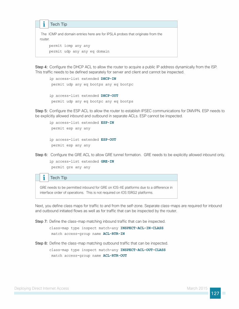
Deploying Direct Internet Access March 2015127
The ICMP and domain entries here are for IPSLA probes that originate from the router.
permit icmp any any
permit udp any any eq domain
Tech Tip
Step 4: Configure the DHCP ACL to allow the router to acquire a public IP address dynamically from the ISP. This traffic needs to be defined separately for server and client and cannot be inspected.
ip access-list extended DHCP-IN permit udp any eq bootps any eq bootpc
ip access-list extended DHCP-OUT permit udp any eq bootpc any eq bootps
Step 5: Configure the ESP ACL to allow the router to establish IPSEC communications for DMVPN. ESP needs to be explicitly allowed inbound and outbound in separate ACLs. ESP cannot be inspected.
ip access-list extended ESP-IN permit esp any any
ip access-list extended ESP-OUT permit esp any any
Step 6: Configure the GRE ACL to allow GRE tunnel formation. GRE needs to be explicitly allowed inbound only.
ip access-list extended GRE-IN permit gre any any
GRE needs to be permitted inbound for GRE on IOS-XE platforms due to a difference in interface order of operations. This is not required on IOS ISRG2 platforms.
Tech Tip
Next, you define class maps for traffic to and from the self-zone. Separate class-maps are required for inbound and outbound initiated flows as well as for traffic that can be inspected by the router.
Step 7: Define the class-map matching inbound traffic that can be inspected.
class-map type inspect match-any INSPECT-ACL-IN-CLASS match access-group name ACL-RTR-IN
Step 8: Define the class-map matching outbound traffic that can be inspected.
class-map type inspect match-any INSPECT-ACL-OUT-CLASS match access-group name ACL-RTR-OUT
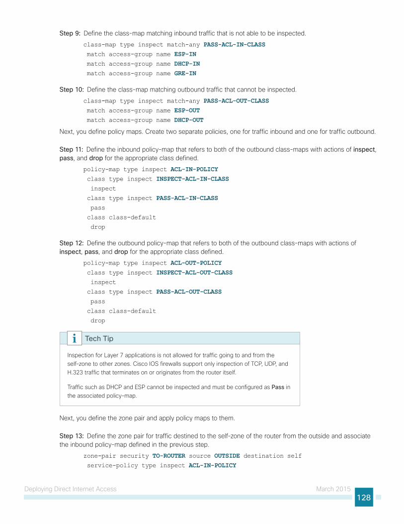
Deploying Direct Internet Access March 2015128
Step 9: Define the class-map matching inbound traffic that is not able to be inspected.
class-map type inspect match-any PASS-ACL-IN-CLASS match access-group name ESP-IN match access-group name DHCP-IN match access-group name GRE-IN
Step 10: Define the class-map matching outbound traffic that cannot be inspected.
class-map type inspect match-any PASS-ACL-OUT-CLASS match access-group name ESP-OUT match access-group name DHCP-OUT
Next, you define policy maps. Create two separate policies, one for traffic inbound and one for traffic outbound.
Step 11: Define the inbound policy-map that refers to both of the outbound class-maps with actions of inspect, pass, and drop for the appropriate class defined.
policy-map type inspect ACL-IN-POLICY class type inspect INSPECT-ACL-IN-CLASS inspect
class type inspect PASS-ACL-IN-CLASS pass
class class-default
drop
Step 12: Define the outbound policy-map that refers to both of the outbound class-maps with actions of inspect, pass, and drop for the appropriate class defined.
policy-map type inspect ACL-OUT-POLICY class type inspect INSPECT-ACL-OUT-CLASS inspect
class type inspect PASS-ACL-OUT-CLASS pass
class class-default
drop
Inspection for Layer 7 applications is not allowed for traffic going to and from the self-zone to other zones. Cisco IOS firewalls support only inspection of TCP, UDP, and H.323 traffic that terminates on or originates from the router itself.
Traffic such as DHCP and ESP cannot be inspected and must be configured as Pass in the associated policy-map.
Tech Tip
Next, you define the zone pair and apply policy maps to them.
Step 13: Define the zone pair for traffic destined to the self-zone of the router from the outside and associate the inbound policy-map defined in the previous step.
zone-pair security TO-ROUTER source OUTSIDE destination self service-policy type inspect ACL-IN-POLICY

Deploying Direct Internet Access March 2015129
Step 14: Define the zone pair for traffic destined from the self-zone of the router to the outside and associate the outbound policy-map defined in the previous step.
zone-pair security FROM-ROUTER source self destination OUTSIDE service-policy type inspect ACL-OUT-POLICY
Procedure 3 Enable and verify zone-based firewall configuration
Step 1: Assign the Internet-facing router interface to the outside security zone. All other interfaces are assigned to the default zone and do not need to be defined.
interface GigabitEthernet0/0/0 description Internet Connection zone-member security OUTSIDE
By default, traffic is allowed to flow between interfaces that are members of the same zone, while a default “deny-all” policy is applied to traffic moving between zones.
This design uses the “default” zone for all inside interfaces, traffic can flow between all interfaces in the default zone.
An interface not defined as part of a security zone is automatically part of the “default” zone. In this configuration, all undefined interface DMVPN tunnels, transit sub-interfaces, and service interfaces such as Cisco UCS-E, and SRE interfaces are included as part of the default zone.
Loopback interfaces are members of the “self” zone and are not assigned to a defined security zone or the default zone.
Tech Tip
Step 2: Verify the interface assignment for the zone firewall and ensure that all required interfaces for the remote site configuration are assigned to the proper zone.
RS34-4451X-1#show zone securityzone self
Description: System defined zone
zone default
Description: System level zone. Interface without zone membership is in this
zone automatically
zone OUTSIDE
Member Interfaces:
GigabitEthernet0/0/0
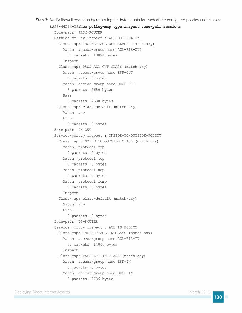
Deploying Direct Internet Access March 2015130
Step 3: Verify firewall operation by reviewing the byte counts for each of the configured policies and classes.
RS32-4451X-2#show policy-map type inspect zone-pair sessions Zone-pair: FROM-ROUTER
Service-policy inspect : ACL-OUT-POLICY
Class-map: INSPECT-ACL-OUT-CLASS (match-any)
Match: access-group name ACL-RTR-OUT
50 packets, 13824 bytes
Inspect
Class-map: PASS-ACL-OUT-CLASS (match-any)
Match: access-group name ESP-OUT
0 packets, 0 bytes
Match: access-group name DHCP-OUT
8 packets, 2680 bytes
Pass
8 packets, 2680 bytes
Class-map: class-default (match-any)
Match: any
Drop
0 packets, 0 bytes
Zone-pair: IN_OUT
Service-policy inspect : INSIDE-TO-OUTSIDE-POLICY
Class-map: INSIDE-TO-OUTSIDE-CLASS (match-any)
Match: protocol ftp
0 packets, 0 bytes
Match: protocol tcp
0 packets, 0 bytes
Match: protocol udp
0 packets, 0 bytes
Match: protocol icmp
0 packets, 0 bytes
Inspect
Class-map: class-default (match-any)
Match: any
Drop
0 packets, 0 bytes
Zone-pair: TO-ROUTER
Service-policy inspect : ACL-IN-POLICY
Class-map: INSPECT-ACL-IN-CLASS (match-any)
Match: access-group name ACL-RTR-IN
52 packets, 14040 bytes
Inspect
Class-map: PASS-ACL-IN-CLASS (match-any)
Match: access-group name ESP-IN
0 packets, 0 bytes
Match: access-group name DHCP-IN
8 packets, 2736 bytes
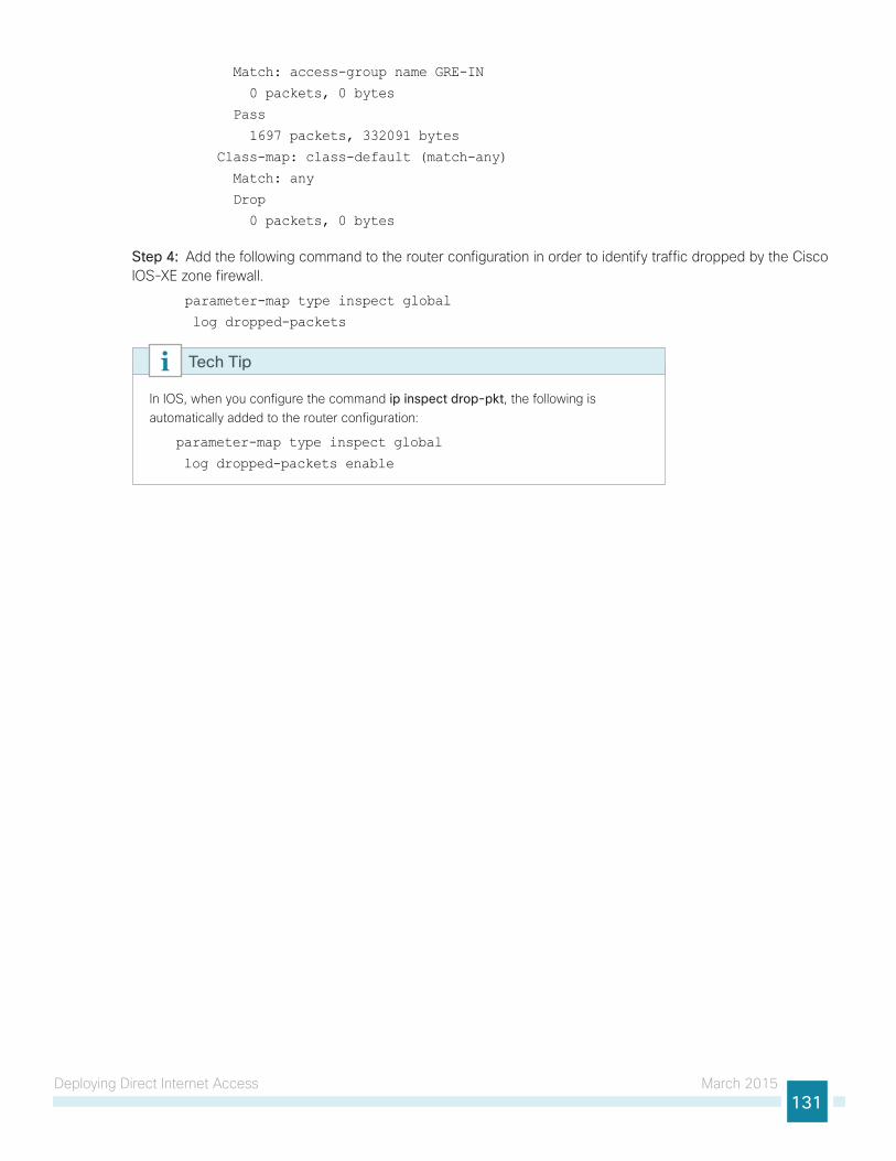
Deploying Direct Internet Access March 2015131
Match: access-group name GRE-IN
0 packets, 0 bytes
Pass
1697 packets, 332091 bytes
Class-map: class-default (match-any)
Match: any
Drop
0 packets, 0 bytes
Step 4: Add the following command to the router configuration in order to identify traffic dropped by the Cisco IOS-XE zone firewall.
parameter-map type inspect global
log dropped-packets
In IOS, when you configure the command ip inspect drop-pkt, the following is automatically added to the router configuration:
parameter-map type inspect global
log dropped-packets enable
Tech Tip
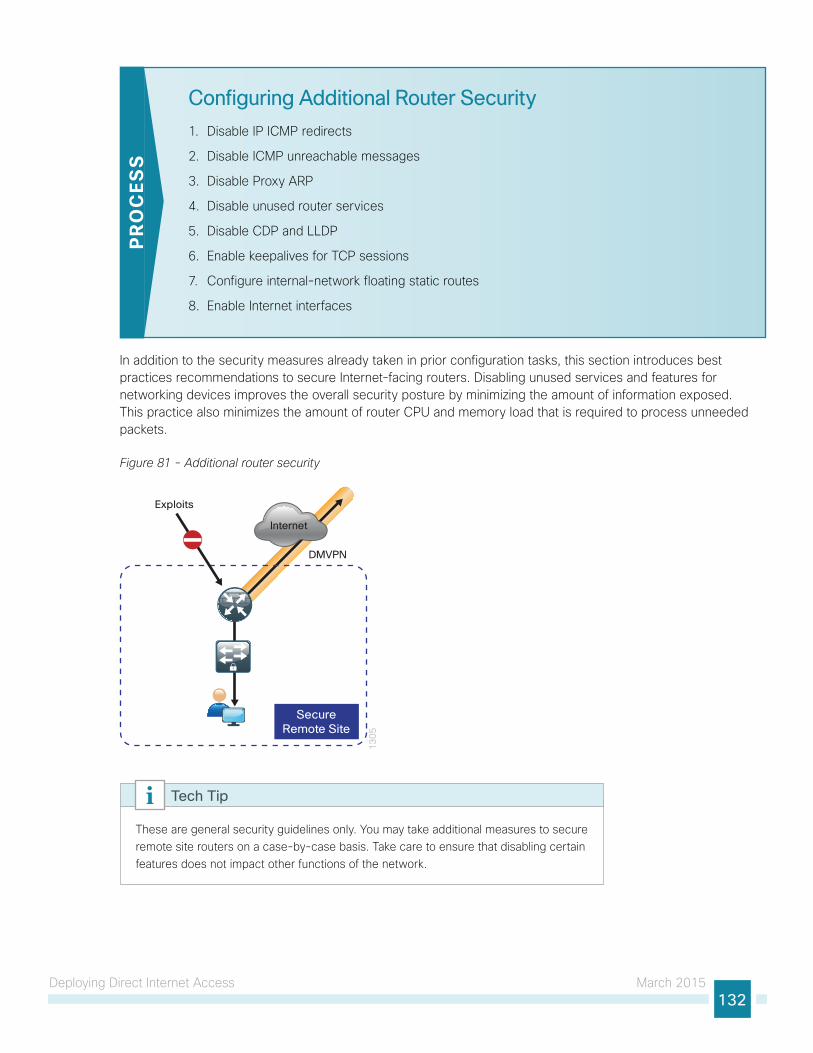
Deploying Direct Internet Access March 2015132
Configuring Additional Router Security
1. Disable IP ICMP redirects
2. Disable ICMP unreachable messages
3. Disable Proxy ARP
4. Disable unused router services
5. Disable CDP and LLDP
6. Enable keepalives for TCP sessions
7. Configure internal-network floating static routes
8. Enable Internet interfaces
PR
OC
ESS
In addition to the security measures already taken in prior configuration tasks, this section introduces best practices recommendations to secure Internet-facing routers. Disabling unused services and features for networking devices improves the overall security posture by minimizing the amount of information exposed. This practice also minimizes the amount of router CPU and memory load that is required to process unneeded packets.
Figure 81 - Additional router security
13
05
Internet
SecureRemote Site
DMVPN
Exploits
These are general security guidelines only. You may take additional measures to secure remote site routers on a case-by-case basis. Take care to ensure that disabling certain features does not impact other functions of the network.
Tech Tip
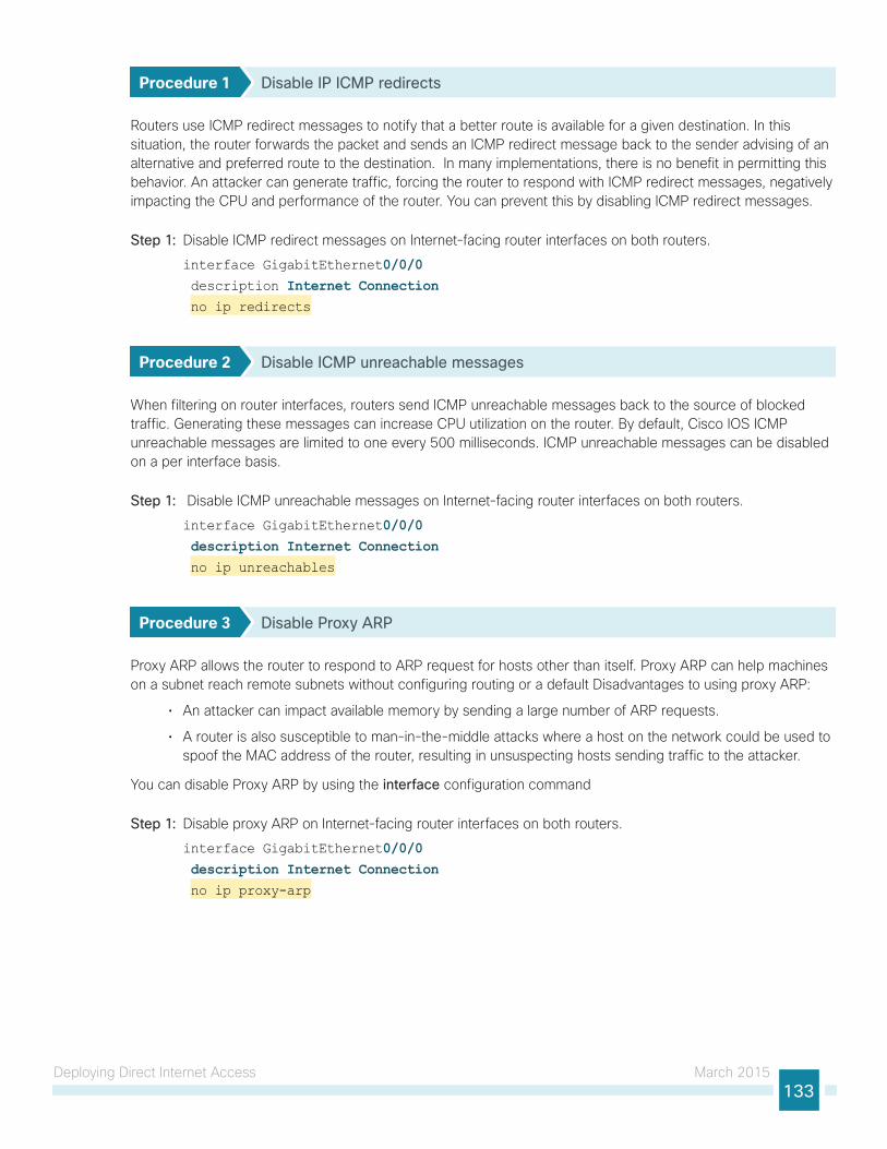
Deploying Direct Internet Access March 2015133
Procedure 1 Disable IP ICMP redirects
Routers use ICMP redirect messages to notify that a better route is available for a given destination. In this situation, the router forwards the packet and sends an ICMP redirect message back to the sender advising of an alternative and preferred route to the destination. In many implementations, there is no benefit in permitting this behavior. An attacker can generate traffic, forcing the router to respond with ICMP redirect messages, negatively impacting the CPU and performance of the router. You can prevent this by disabling ICMP redirect messages.
Step 1: Disable ICMP redirect messages on Internet-facing router interfaces on both routers.
interface GigabitEthernet0/0/0 description Internet Connection no ip redirects
Procedure 2 Disable ICMP unreachable messages
When filtering on router interfaces, routers send ICMP unreachable messages back to the source of blocked traffic. Generating these messages can increase CPU utilization on the router. By default, Cisco IOS ICMP unreachable messages are limited to one every 500 milliseconds. ICMP unreachable messages can be disabled on a per interface basis.
Step 1: Disable ICMP unreachable messages on Internet-facing router interfaces on both routers.
interface GigabitEthernet0/0/0 description Internet Connection no ip unreachables
Procedure 3 Disable Proxy ARP
Proxy ARP allows the router to respond to ARP request for hosts other than itself. Proxy ARP can help machines on a subnet reach remote subnets without configuring routing or a default Disadvantages to using proxy ARP:
• An attacker can impact available memory by sending a large number of ARP requests.
• A router is also susceptible to man-in-the-middle attacks where a host on the network could be used to spoof the MAC address of the router, resulting in unsuspecting hosts sending traffic to the attacker.
You can disable Proxy ARP by using the interface configuration command
Step 1: Disable proxy ARP on Internet-facing router interfaces on both routers.
interface GigabitEthernet0/0/0 description Internet Connection no ip proxy-arp
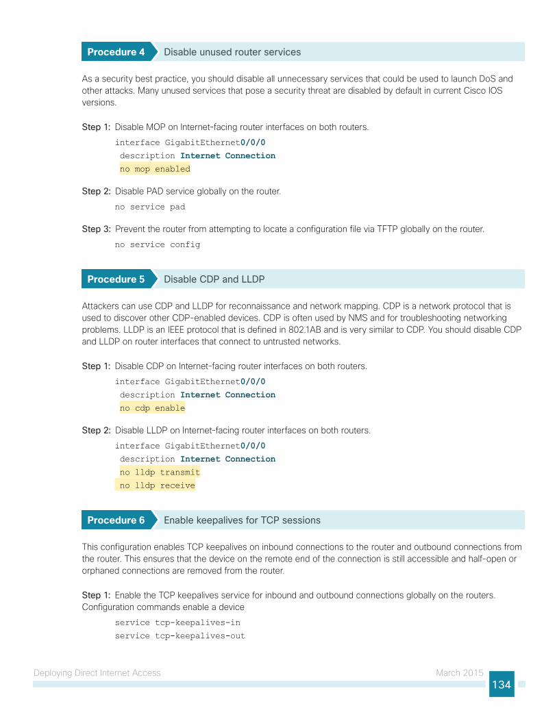
Deploying Direct Internet Access March 2015134
Procedure 4 Disable unused router services
As a security best practice, you should disable all unnecessary services that could be used to launch DoS and other attacks. Many unused services that pose a security threat are disabled by default in current Cisco IOS versions.
Step 1: Disable MOP on Internet-facing router interfaces on both routers.
interface GigabitEthernet0/0/0 description Internet Connection no mop enabled
Step 2: Disable PAD service globally on the router.
no service pad
Step 3: Prevent the router from attempting to locate a configuration file via TFTP globally on the router.
no service config
Procedure 5 Disable CDP and LLDP
Attackers can use CDP and LLDP for reconnaissance and network mapping. CDP is a network protocol that is used to discover other CDP-enabled devices. CDP is often used by NMS and for troubleshooting networking problems. LLDP is an IEEE protocol that is defined in 802.1AB and is very similar to CDP. You should disable CDP and LLDP on router interfaces that connect to untrusted networks.
Step 1: Disable CDP on Internet-facing router interfaces on both routers.
interface GigabitEthernet0/0/0 description Internet Connection no cdp enable
Step 2: Disable LLDP on Internet-facing router interfaces on both routers.
interface GigabitEthernet0/0/0 description Internet Connection no lldp transmit
no lldp receive
Procedure 6 Enable keepalives for TCP sessions
This configuration enables TCP keepalives on inbound connections to the router and outbound connections from the router. This ensures that the device on the remote end of the connection is still accessible and half-open or orphaned connections are removed from the router.
Step 1: Enable the TCP keepalives service for inbound and outbound connections globally on the routers. Configuration commands enable a device
service tcp-keepalives-in
service tcp-keepalives-out
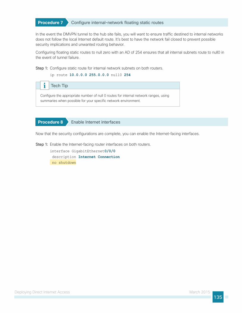
Deploying Direct Internet Access March 2015135
Procedure 7 Configure internal-network floating static routes
In the event the DMVPN tunnel to the hub site fails, you will want to ensure traffic destined to internal networks does not follow the local Internet default route. It’s best to have the network fail closed to prevent possible security implications and unwanted routing behavior.
Configuring floating static routes to null zero with an AD of 254 ensures that all internal subnets route to null0 in the event of tunnel failure.
Step 1: Configure static route for internal network subnets on both routers.
ip route 10.0.0.0 255.0.0.0 null0 254
Configure the appropriate number of null 0 routes for internal network ranges, using summaries when possible for your specific network environment.
Tech Tip
Procedure 8 Enable Internet interfaces
Now that the security configurations are complete, you can enable the Internet-facing interfaces.
Step 1: Enable the Internet-facing router interfaces on both routers.
interface GigabitEthernet0/0/0 description Internet Connection no shutdown
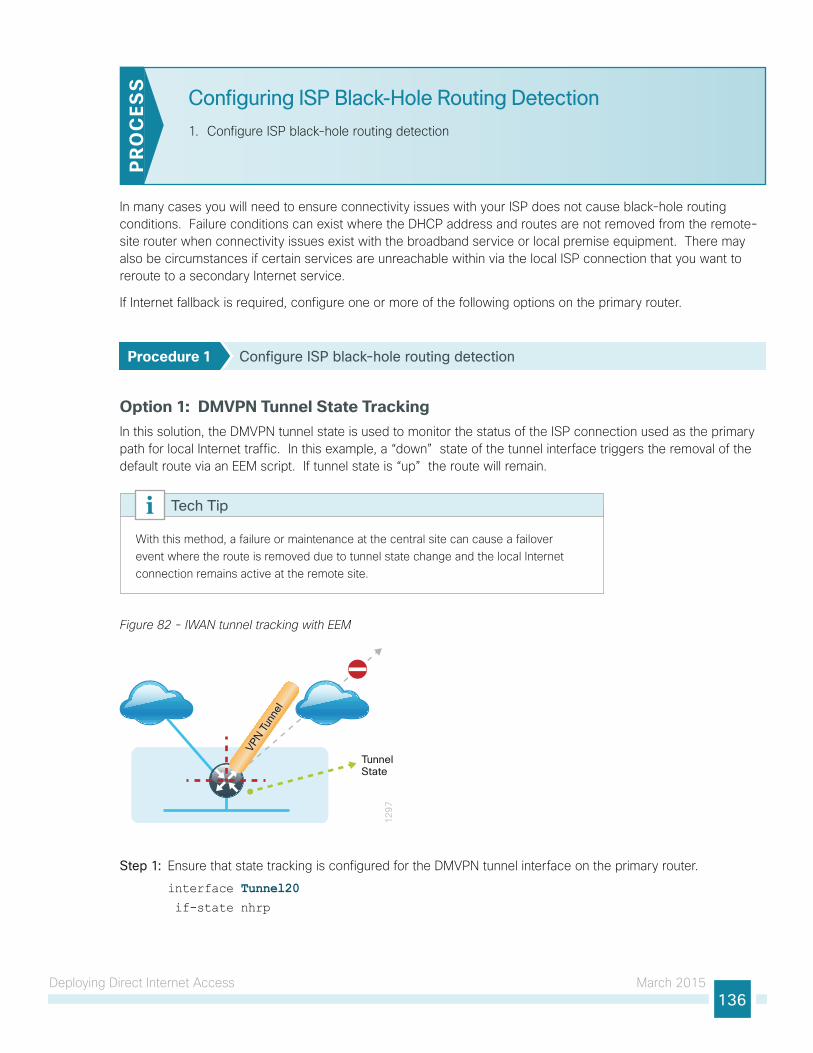
Deploying Direct Internet Access March 2015136
Configuring ISP Black-Hole Routing Detection
1. Configure ISP black-hole routing detectionP
RO
CES
S
In many cases you will need to ensure connectivity issues with your ISP does not cause black-hole routing conditions. Failure conditions can exist where the DHCP address and routes are not removed from the remote-site router when connectivity issues exist with the broadband service or local premise equipment. There may also be circumstances if certain services are unreachable within via the local ISP connection that you want to reroute to a secondary Internet service.
If Internet fallback is required, configure one or more of the following options on the primary router.
Procedure 1 Configure ISP black-hole routing detection
Option 1: DMVPN Tunnel State TrackingIn this solution, the DMVPN tunnel state is used to monitor the status of the ISP connection used as the primary path for local Internet traffic. In this example, a “down” state of the tunnel interface triggers the removal of the default route via an EEM script. If tunnel state is “up” the route will remain.
With this method, a failure or maintenance at the central site can cause a failover event where the route is removed due to tunnel state change and the local Internet connection remains active at the remote site.
Tech Tip
Figure 82 - IWAN tunnel tracking with EEM
12
97
VPN T
unne
l
TunnelState
Step 1: Ensure that state tracking is configured for the DMVPN tunnel interface on the primary router.
interface Tunnel20 if-state nhrp
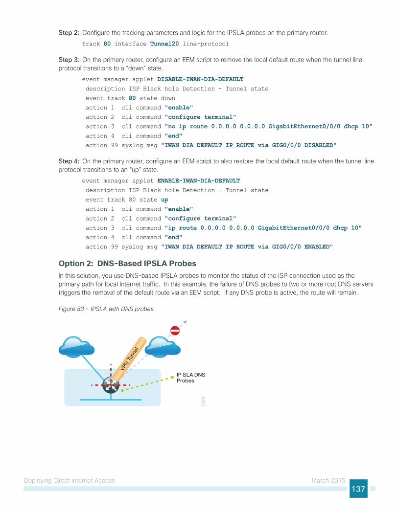
Deploying Direct Internet Access March 2015137
Step 2: Configure the tracking parameters and logic for the IPSLA probes on the primary router.
track 80 interface Tunnel20 line-protocol
Step 3: On the primary router, configure an EEM script to remove the local default route when the tunnel line protocol transitions to a “down” state.
event manager applet DISABLE-IWAN-DIA-DEFAULT description ISP Black hole Detection - Tunnel state
event track 80 state down action 1 cli command "enable" action 2 cli command "configure terminal" action 3 cli command "no ip route 0.0.0.0 0.0.0.0 GigabitEthernet0/0/0 dhcp 10" action 4 cli command "end" action 99 syslog msg "IWAN DIA DEFAULT IP ROUTE via GIG0/0/0 DISABLED"
Step 4: On the primary router, configure an EEM script to also restore the local default route when the tunnel line protocol transitions to an “up” state.
event manager applet ENABLE-IWAN-DIA-DEFAULT description ISP Black hole Detection - Tunnel state
event track 80 state up action 1 cli command "enable" action 2 cli command "configure terminal" action 3 cli command "ip route 0.0.0.0 0.0.0.0 GigabitEthernet0/0/0 dhcp 10" action 4 cli command "end" action 99 syslog msg "IWAN DIA DEFAULT IP ROUTE via GIG0/0/0 ENABLED"
Option 2: DNS-Based IPSLA ProbesIn this solution, you use DNS-based IPSLA probes to monitor the status of the ISP connection used as the primary path for local Internet traffic. In this example, the failure of DNS probes to two or more root DNS servers triggers the removal of the default route via an EEM script. If any DNS probe is active, the route will remain.
Figure 83 - IPSLA with DNS probes
12
99
VPN T
unne
l
IP SLA DNSProbes
Deploying Direct Internet Access March 2015138
For DNS-based IPSLA probes to function, you need to ensure that DNS or “domain” is permitted in the ZBFW outbound ACL, from the self-zone to the OUTSIDE zone.
Example:
ip access-list extended ACL-RTR-OUT
permit udp any any eq domain
Tech Tip
Step 1: On the primary router, configure the VRF-aware IPSLA DNS probes.
ip sla 118 dns d.root-servers.net name-server 199.7.91.13 vrf IWAN-TRANSPORT-3 threshold 1000 timeout 3000 frequency 15ip sla schedule 118 life forever start-time now
ip sla 119 dns b.root-servers.net name-server 192.228.79.201 vrf IWAN-TRANSPORT-3 threshold 1000 timeout 3000 frequency 15ip sla schedule 119 life forever start-time now
When configuring DNS probes, you should specify the hostname of the DNS server itself. That asks the DNS server to resolve for itself, allowing the use of root DNS servers.
Tech Tip
Step 2: On the primary router, configure the tracking parameters and logic for the IPSLA probes.
track 73 ip sla 118 reachabilitytrack 74 ip sla 119 reachability!
track 100 list boolean or object 73 object 74
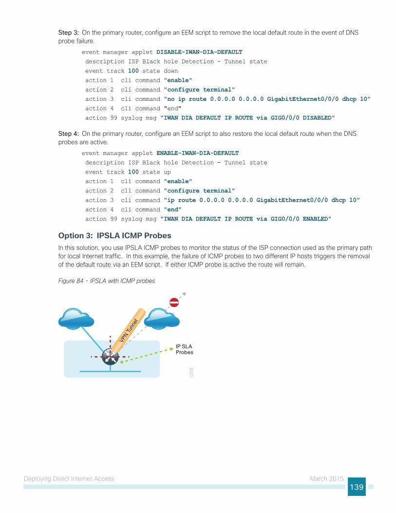
Deploying Direct Internet Access March 2015139
Step 3: On the primary router, configure an EEM script to remove the local default route in the event of DNS probe failure.
event manager applet DISABLE-IWAN-DIA-DEFAULT description ISP Black hole Detection - Tunnel state
event track 100 state down action 1 cli command "enable" action 2 cli command "configure terminal" action 3 cli command "no ip route 0.0.0.0 0.0.0.0 GigabitEthernet0/0/0 dhcp 10" action 4 cli command "end"
action 99 syslog msg "IWAN DIA DEFAULT IP ROUTE via GIG0/0/0 DISABLED"
Step 4: On the primary router, configure an EEM script to also restore the local default route when the DNS probes are active.
event manager applet ENABLE-IWAN-DIA-DEFAULT description ISP Black hole Detection - Tunnel state
event track 100 state up action 1 cli command "enable" action 2 cli command "configure terminal" action 3 cli command "ip route 0.0.0.0 0.0.0.0 GigabitEthernet0/0/0 dhcp 10" action 4 cli command "end" action 99 syslog msg "IWAN DIA DEFAULT IP ROUTE via GIG0/0/0 ENABLED"
Option 3: IPSLA ICMP ProbesIn this solution, you use IPSLA ICMP probes to monitor the status of the ISP connection used as the primary path for local Internet traffic. In this example, the failure of ICMP probes to two different IP hosts triggers the removal of the default route via an EEM script. If either ICMP probe is active the route will remain.
Figure 84 - IPSLA with ICMP probes
12
98
VPN T
unne
l
IP SLAProbes
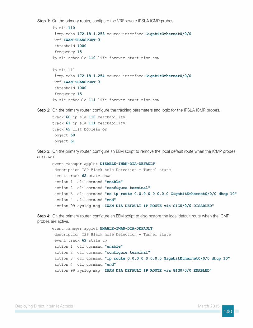
Deploying Direct Internet Access March 2015140
Step 1: On the primary router, configure the VRF-aware IPSLA ICMP probes.
ip sla 110 icmp-echo 172.18.1.253 source-interface GigabitEthernet0/0/0 vrf IWAN-TRANSPORT-3 threshold 1000 frequency 15ip sla schedule 110 life forever start-time now
ip sla 111
icmp-echo 172.18.1.254 source-interface GigabitEthernet0/0/0 vrf IWAN-TRANSPORT-3 threshold 1000 frequency 15ip sla schedule 111 life forever start-time now
Step 2: On the primary router, configure the tracking parameters and logic for the IPSLA ICMP probes.
track 60 ip sla 110 reachabilitytrack 61 ip sla 111 reachabilitytrack 62 list boolean or object 60 object 61
Step 3: On the primary router, configure an EEM script to remove the local default route when the ICMP probes are down.
event manager applet DISABLE-IWAN-DIA-DEFAULT description ISP Black hole Detection - Tunnel state
event track 62 state down action 1 cli command "enable" action 2 cli command "configure terminal" action 3 cli command "no ip route 0.0.0.0 0.0.0.0 GigabitEthernet0/0/0 dhcp 10" action 4 cli command "end" action 99 syslog msg "IWAN DIA DEFAULT IP ROUTE via GIG0/0/0 DISABLED"
Step 4: On the primary router, configure an EEM script to also restore the local default route when the ICMP probes are active.
event manager applet ENABLE-IWAN-DIA-DEFAULT description ISP Black hole Detection - Tunnel state
event track 62 state up action 1 cli command "enable" action 2 cli command "configure terminal" action 3 cli command "ip route 0.0.0.0 0.0.0.0 GigabitEthernet0/0/0 dhcp 10" action 4 cli command "end" action 99 syslog msg "IWAN DIA DEFAULT IP ROUTE via GIG0/0/0 ENABLED"
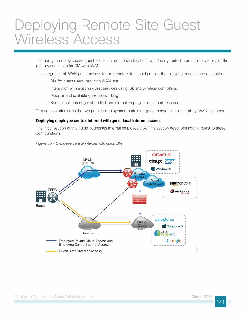
Deploying Remote Site Guest Wireless Access March 2015141
Deploying Remote Site Guest Wireless Access
The ability to deploy secure guest access in remote site locations with locally routed Internet traffic is one of the primary use cases for DIA with IWAN.
The integration of IWAN guest access to the remote-site should provide the following benefits and capabilities:
• DIA for guest users, reducing WAN use
• Integration with existing guest services using ISE and wireless controllers.
• Modular and scalable guest networking
• Secure isolation of guest traffic from internal employee traffic and resources
This section addresses the two primary deployment models for guest networking required by IWAN customers.
Deploying employee central Internet with guest local Internet accessThe initial section of this guide addresses internal employee DIA. This section describes adding guest to these configurations.
Figure 85 - Employee central Internet with guest DIA
13
07
Internet
PrivateCloud
VirtualPrivate Cloud
Public Cloud
Ciscowebex
MPLS (IP-VPN)
Employee Private Cloud Access andEmployee Central Internet Access
Guest Direct Internet Access
Branch
ZBFW
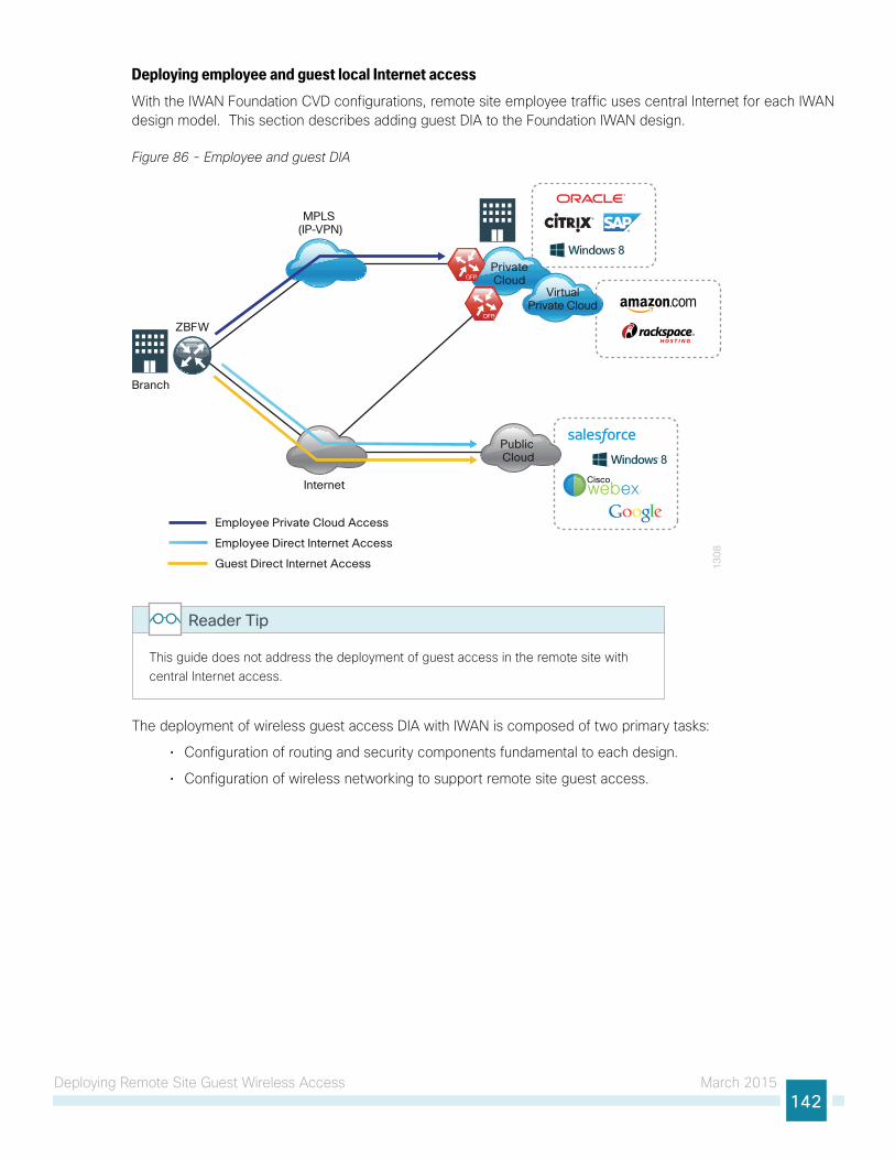
Deploying Remote Site Guest Wireless Access March 2015142
Deploying employee and guest local Internet accessWith the IWAN Foundation CVD configurations, remote site employee traffic uses central Internet for each IWAN design model. This section describes adding guest DIA to the Foundation IWAN design.
Figure 86 - Employee and guest DIA
13
08
Internet
PrivateCloud
VirtualPrivate Cloud
Public Cloud
Ciscowebex
MPLS (IP-VPN)
Employee Private Cloud Access
Employee Direct Internet Access
Guest Direct Internet Access
Branch
ZBFW
This guide does not address the deployment of guest access in the remote site with central Internet access.
Reader Tip
The deployment of wireless guest access DIA with IWAN is composed of two primary tasks:
• Configuration of routing and security components fundamental to each design.
• Configuration of wireless networking to support remote site guest access.
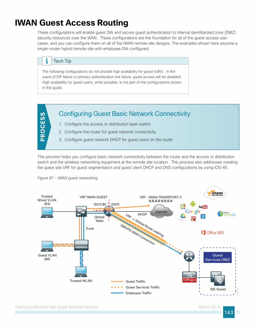
Deploying Remote Site Guest Wireless Access March 2015143
IWAN Guest Access RoutingThese configurations will enable guest DIA and secure guest authentication to internal demilitarized zone (DMZ) security resources over the WAN. These configurations are the foundation for all of the guest-access use-cases, and you can configure them on all of the IWAN remote site designs. The examples shown here assume a single-router hybrid remote site with employee DIA configured.
The following configurations do not provide high availability for guest traffic. In the event of ISP failure or primary authentication link failure, guest access will be disabled. High availability for guest users, while possible, is not part of the configurations shown in this guide.
Tech Tip
Configuring Guest Basic Network Connectivity
1. Configure the access or distribution layer switch
2. Configure the router for guest network connectivity
3. Configure guest network DHCP for guest users on the routerPR
OC
ESS
This process helps you configure basic network connectivity between the router and the access or distribution switch and the wireless networking equipment at the remote site location. This process also addresses creating the guest site VRF for guest segmentation and guest client DHCP and DNS configurations by using IOS-XE.
Figure 87 - IWAN guest networking
13
10
G0/2.80
DMVPN WAN Connection
DHCPGlobalTable
Internet
Trusted Wired VLAN
(64)
Guest VLAN(80)
Trusted WLAN
G0/0
ISE-Guest
GuestServices DMZ
VRF - IWAN-TRANSPORT-20.0.0.0 0.0.0.0
Guest Traffic
Guest Services Traffic
Employee Traffic
Trunk
VRF -> Global Route Leaking
VRF IWAN-GUEST
Ciscowebex
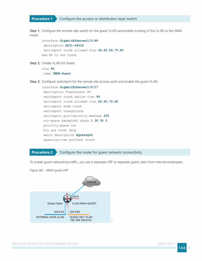
Deploying Remote Site Guest Wireless Access March 2015144
Procedure 1 Configure the access or distribution layer switch
Step 1: Configure the remote-site switch for the guest VLAN and enable trunking of this VLAN to the WAN router.
interface GigabitEthernet1/0/48 description RS31-4451X switchport trunk allowed vlan 64,65,69,70,80add 80 to the trunk
Step 2: Create VLAN for Guest
vlan 80 name IWAN-Guest
Step 3: Configure switchport for the remote site access point and enable the guest VLAN.
interface GigabitEthernet1/0/17 description FlexConnect AP
switchport trunk native vlan 99 switchport trunk allowed vlan 64,65,70,80 switchport mode trunk
switchport nonegotiate
switchport port-security maximum 255 srr-queue bandwidth share 1 30 35 5 priority-queue out
mls qos trust dscp
macro description EgressQoS spanning-tree portfast trunk
Procedure 2 Configure the router for guest network connectivity
To isolate guest networking traffic, you use a separate VRF to separate guest users from internal employees.
Figure 88 - IWAN guest VRF
VLAN IWAN-GUEST
INTERNAL-DATA VLAN
13
11
Internet
G0/0
G0/2.80G0/2.64
Global Table
GUEST-NET VLAN192.168.192.0/24
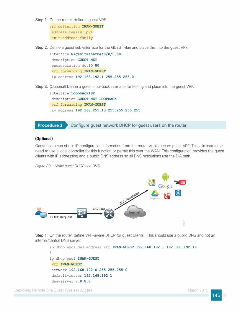
Deploying Remote Site Guest Wireless Access March 2015145
Step 1: On the router, define a guest VRF.
vrf definition IWAN-GUEST address-family ipv4
exit-address-family
Step 2: Define a guest sub-interface for the GUEST vlan and place this into the guest VRF.
interface GigabitEthernet0/0/2.80 description GUEST-NET encapsulation dot1Q 80 vrf forwarding IWAN-GUEST ip address 192.168.192.1 255.255.255.0
Step 3: (Optional) Define a guest loop-back interface for testing and place into the guest VRF.
interface Loopback192 description GUEST-NET LOOPBACK vrf forwarding IWAN-GUEST ip address 192.168.255.13 255.255.255.255
Procedure 3 Configure guest network DHCP for guest users on the router
(Optional)Guest users can obtain IP configuration information from the router within secure guest VRF. This eliminates the need to use a local controller for this function or permit this over the WAN. This configuration provides the guest clients with IP addressing and a public DNS address so all DNS resolutions use the DIA path.
Figure 89 - IWAN guest DHCP and DNS
13
15
Internet
DHCP Request
G0/2.80
DNS Resolution
Step 1: On the router, define VRF-aware DHCP for guest clients. This should use a public DNS and not an internal/central DNS server.
ip dhcp excluded-address vrf IWAN-GUEST 192.168.192.1 192.168.192.19!
ip dhcp pool IWAN-GUEST vrf IWAN-GUEST network 192.168.192.0 255.255.255.0 default-router 192.168.192.1 dns-server 8.8.8.8
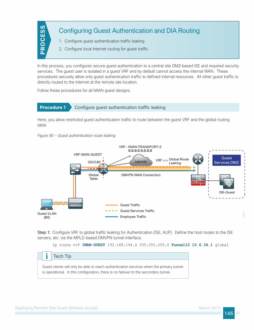
Deploying Remote Site Guest Wireless Access March 2015146
Configuring Guest Authentication and DIA Routing
1. Configure guest authentication traffic leaking
2. Configure local Internet routing for guest trafficP
RO
CES
S
In this process, you configures secure guest authentication to a central site DMZ–based ISE and required security services. The guest user is isolated in a guest VRF and by default cannot access the internal WAN. These procedures securely allow only guest authentication traffic to defined internal resources. All other guest traffic is directly routed to the Internet at the remote site location.
Follow these procedures for all IWAN guest designs.
Procedure 1 Configure guest authentication traffic leaking
Here, you allow restricted guest authentication traffic to route between the guest VRF and the global routing table.
Figure 90 - Guest authentication route leaking
Internet
13
12
G0/2.80
GlobalTable
Guest VLAN(80)
ISE-Guest
GuestServices DMZ
VRF - IWAN-TRANSPORT-20.0.0.0 0.0.0.0
Guest Traffic
Guest Services Traffic
Employee Traffic
DMVPN WAN Connection
VRF IWAN-GUEST
VRF <-> Global RouteLeaking
Step 1: Configure VRF to global traffic leaking for Authentication (ISE, AUP). Define the host routes to the ISE servers, etc. via the MPLS-based DMVPN tunnel interface.
ip route vrf IWAN-GUEST 192.168.144.0 255.255.255.0 Tunnel10 10.6.34.1 global
Guest clients will only be able to reach authentication services when the primary tunnel is operational. In this configuration, there is no failover to the secondary tunnel.
Tech Tip
Deploying Remote Site Guest Wireless Access March 2015147
Step 2: Configure Global to VRF routing for traffic returning from the global for Authentication traffic.
ip route 192.168.192.0 255.255.255.0 GigabitEthernet0/0/2.80ip route 192.168.255.13 255.255.255.255 Loopback192
Step 3: Verify that guest hosts can get DHCP addresses and can reach the guest default gateway and loopback addresses.
Clients will not be able to reach internal authentication services until NAT is properly configured.
Tech Tip
Procedure 2 Configure local Internet routing for guest traffic
For guest DIA to work properly, you must add a static default route in the guest VRF to the IWAN router. This directs guest traffic directly to the outside transport VRF outside the DMVPN tunnel and to the Internet local to the remote site location.
Step 1: Configure an outbound default route in the guest VRF.
ip route vrf IWAN-GUEST 0.0.0.0 0.0.0.0 GigabitEthernet0/0/1 dhcp 10
Clients will not be able to reach the Internet until VRF-aware NAT is properly configured. This NAT process is different from the employee DIA NAT configured in the global table.
Tech Tip
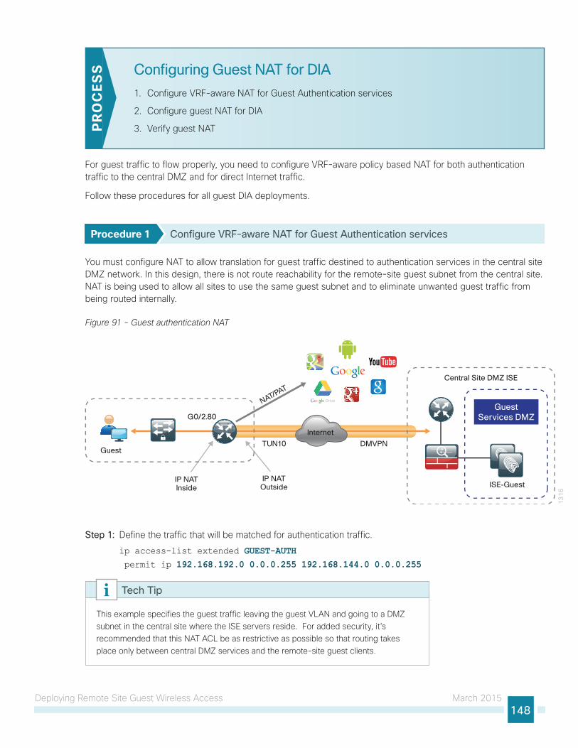
Deploying Remote Site Guest Wireless Access March 2015148
Configuring Guest NAT for DIA
1. Configure VRF-aware NAT for Guest Authentication services
2. Configure guest NAT for DIA
3. Verify guest NATPR
OC
ESS
For guest traffic to flow properly, you need to configure VRF-aware policy based NAT for both authentication traffic to the central DMZ and for direct Internet traffic.
Follow these procedures for all guest DIA deployments.
Procedure 1 Configure VRF-aware NAT for Guest Authentication services
You must configure NAT to allow translation for guest traffic destined to authentication services in the central site DMZ network. In this design, there is not route reachability for the remote-site guest subnet from the central site. NAT is being used to allow all sites to use the same guest subnet and to eliminate unwanted guest traffic from being routed internally.
Figure 91 - Guest authentication NAT
13
16
Internet
DMVPN
IP NATInside
G0/2.80
IP NATOutside
NAT/PAT
TUN10Guest
ISE-Guest
GuestServices DMZ
Central Site DMZ ISE
Step 1: Define the traffic that will be matched for authentication traffic.
ip access-list extended GUEST-AUTH permit ip 192.168.192.0 0.0.0.255 192.168.144.0 0.0.0.255
This example specifies the guest traffic leaving the guest VLAN and going to a DMZ subnet in the central site where the ISE servers reside. For added security, it’s recommended that this NAT ACL be as restrictive as possible so that routing takes place only between central DMZ services and the remote-site guest clients.
Tech Tip
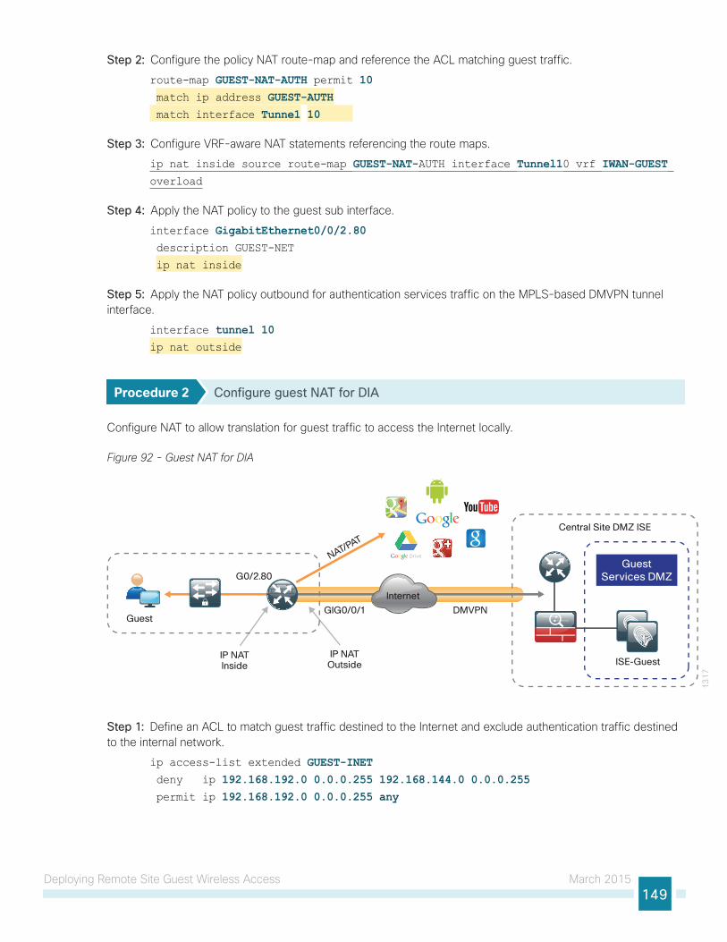
Deploying Remote Site Guest Wireless Access March 2015149
Step 2: Configure the policy NAT route-map and reference the ACL matching guest traffic.
route-map GUEST-NAT-AUTH permit 10 match ip address GUEST-AUTH match interface Tunne1 10
Step 3: Configure VRF-aware NAT statements referencing the route maps.
ip nat inside source route-map GUEST-NAT-AUTH interface Tunnel10 vrf IWAN-GUEST overload
Step 4: Apply the NAT policy to the guest sub interface.
interface GigabitEthernet0/0/2.80 description GUEST-NET
ip nat inside
Step 5: Apply the NAT policy outbound for authentication services traffic on the MPLS-based DMVPN tunnel interface.
interface tunnel 10ip nat outside
Procedure 2 Configure guest NAT for DIA
Configure NAT to allow translation for guest traffic to access the Internet locally.
Figure 92 - Guest NAT for DIA
13
17
DMVPN
IP NATInside
G0/2.80
IP NATOutside
NAT/PAT
GIG0/0/1Guest
Internet
ISE-Guest
GuestServices DMZ
Central Site DMZ ISE
Step 1: Define an ACL to match guest traffic destined to the Internet and exclude authentication traffic destined to the internal network.
ip access-list extended GUEST-INET deny ip 192.168.192.0 0.0.0.255 192.168.144.0 0.0.0.255 permit ip 192.168.192.0 0.0.0.255 any
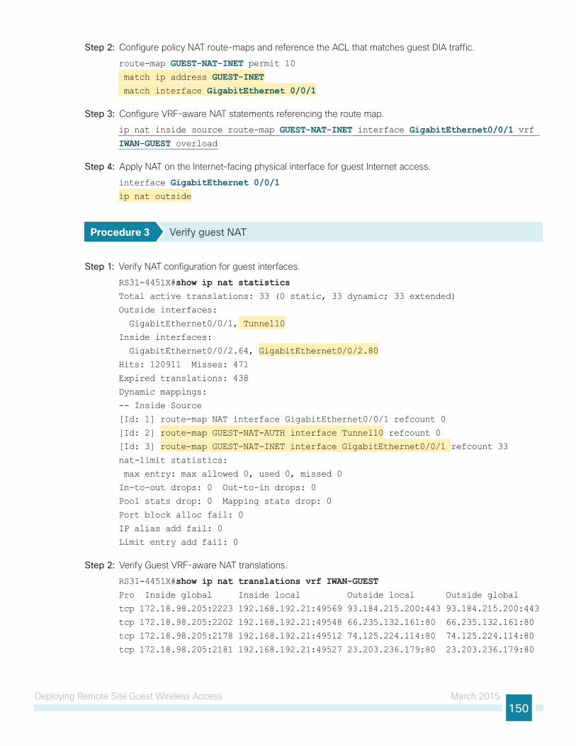
Deploying Remote Site Guest Wireless Access March 2015150
Step 2: Configure policy NAT route-maps and reference the ACL that matches guest DIA traffic.
route-map GUEST-NAT-INET permit 10 match ip address GUEST-INET match interface GigabitEthernet 0/0/1
Step 3: Configure VRF-aware NAT statements referencing the route map.
ip nat inside source route-map GUEST-NAT-INET interface GigabitEthernet0/0/1 vrf IWAN-GUEST overload
Step 4: Apply NAT on the Internet-facing physical interface for guest Internet access.
interface GigabitEthernet 0/0/1ip nat outside
Procedure 3 Verify guest NAT
Step 1: Verify NAT configuration for guest interfaces.
RS31-4451X#show ip nat statisticsTotal active translations: 33 (0 static, 33 dynamic; 33 extended)
Outside interfaces:
GigabitEthernet0/0/1, Tunnel10
Inside interfaces:
GigabitEthernet0/0/2.64, GigabitEthernet0/0/2.80
Hits: 120911 Misses: 471
Expired translations: 438
Dynamic mappings:
-- Inside Source
[Id: 1] route-map NAT interface GigabitEthernet0/0/1 refcount 0
[Id: 2] route-map GUEST-NAT-AUTH interface Tunnel10 refcount 0
[Id: 3] route-map GUEST-NAT-INET interface GigabitEthernet0/0/1 refcount 33
nat-limit statistics:
max entry: max allowed 0, used 0, missed 0
In-to-out drops: 0 Out-to-in drops: 0
Pool stats drop: 0 Mapping stats drop: 0
Port block alloc fail: 0
IP alias add fail: 0
Limit entry add fail: 0
Step 2: Verify Guest VRF-aware NAT translations.
RS31-4451X#show ip nat translations vrf IWAN-GUESTPro Inside global Inside local Outside local Outside global
tcp 172.18.98.205:2223 192.168.192.21:49569 93.184.215.200:443 93.184.215.200:443
tcp 172.18.98.205:2202 192.168.192.21:49548 66.235.132.161:80 66.235.132.161:80
tcp 172.18.98.205:2178 192.168.192.21:49512 74.125.224.114:80 74.125.224.114:80
tcp 172.18.98.205:2181 192.168.192.21:49527 23.203.236.179:80 23.203.236.179:80
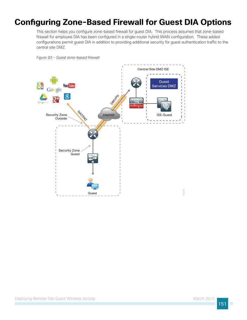
Deploying Remote Site Guest Wireless Access March 2015151
Configuring Zone-Based Firewall for Guest DIA OptionsThis section helps you configure zone-based firewall for guest DIA. This process assumes that zone-based firewall for employee DIA has been configured in a single-router hybrid IWAN configuration. These added configurations permit guest DIA in addition to providing additional security for guest authentication traffic to the central site DMZ.
Figure 93 - Guest zone-based firewall
13
18
DMVPN
Security ZoneOutside
Security ZoneGuest
NAT/PAT
Guest
Internet ISE-Guest
GuestServices DMZ
Central Site DMZ ISE
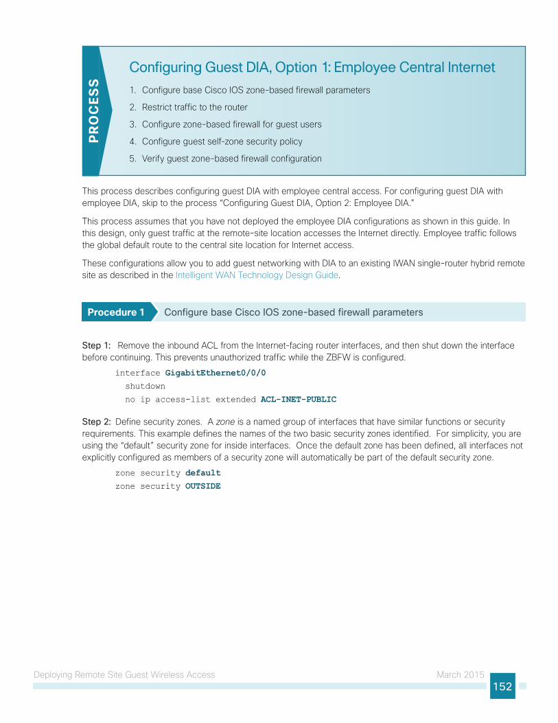
Deploying Remote Site Guest Wireless Access March 2015152
Configuring Guest DIA, Option 1: Employee Central Internet
1. Configure base Cisco IOS zone-based firewall parameters
2. Restrict traffic to the router
3. Configure zone-based firewall for guest users
4. Configure guest self-zone security policy
5. Verify guest zone-based firewall configuration
PR
OC
ESS
This process describes configuring guest DIA with employee central access. For configuring guest DIA with employee DIA, skip to the process “Configuring Guest DIA, Option 2: Employee DIA.”
This process assumes that you have not deployed the employee DIA configurations as shown in this guide. In this design, only guest traffic at the remote-site location accesses the Internet directly. Employee traffic follows the global default route to the central site location for Internet access.
These configurations allow you to add guest networking with DIA to an existing IWAN single-router hybrid remote site as described in the Intelligent WAN Technology Design Guide.
Procedure 1 Configure base Cisco IOS zone-based firewall parameters
Step 1: Remove the inbound ACL from the Internet-facing router interfaces, and then shut down the interface before continuing. This prevents unauthorized traffic while the ZBFW is configured.
interface GigabitEthernet0/0/0 shutdown
no ip access-list extended ACL-INET-PUBLIC
Step 2: Define security zones. A zone is a named group of interfaces that have similar functions or security requirements. This example defines the names of the two basic security zones identified. For simplicity, you are using the “default” security zone for inside interfaces. Once the default zone has been defined, all interfaces not explicitly configured as members of a security zone will automatically be part of the default security zone.
zone security defaultzone security OUTSIDE
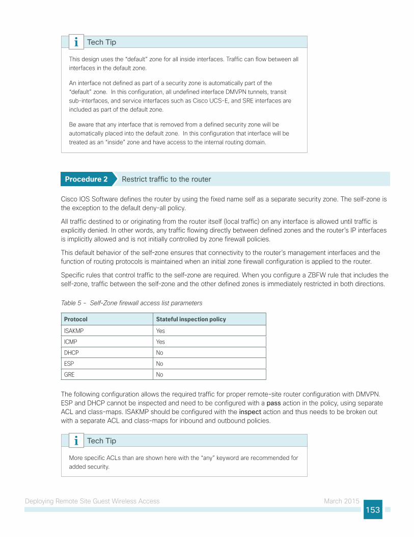
Deploying Remote Site Guest Wireless Access March 2015153
This design uses the “default” zone for all inside interfaces. Traffic can flow between all interfaces in the default zone.
An interface not defined as part of a security zone is automatically part of the “default” zone. In this configuration, all undefined interface DMVPN tunnels, transit sub-interfaces, and service interfaces such as Cisco UCS-E, and SRE interfaces are included as part of the default zone.
Be aware that any interface that is removed from a defined security zone will be automatically placed into the default zone. In this configuration that interface will be treated as an “inside” zone and have access to the internal routing domain.
Tech Tip
Procedure 2 Restrict traffic to the router
Cisco IOS Software defines the router by using the fixed name self as a separate security zone. The self-zone is the exception to the default deny-all policy.
All traffic destined to or originating from the router itself (local traffic) on any interface is allowed until traffic is explicitly denied. In other words, any traffic flowing directly between defined zones and the router’s IP interfaces is implicitly allowed and is not initially controlled by zone firewall policies.
This default behavior of the self-zone ensures that connectivity to the router’s management interfaces and the function of routing protocols is maintained when an initial zone firewall configuration is applied to the router.
Specific rules that control traffic to the self-zone are required. When you configure a ZBFW rule that includes the self-zone, traffic between the self-zone and the other defined zones is immediately restricted in both directions.
Table 5 - Self-Zone firewall access list parameters
Protocol Stateful inspection policy
ISAKMP Yes
ICMP Yes
DHCP No
ESP No
GRE No
The following configuration allows the required traffic for proper remote-site router configuration with DMVPN. ESP and DHCP cannot be inspected and need to be configured with a pass action in the policy, using separate ACL and class-maps. ISAKMP should be configured with the inspect action and thus needs to be broken out with a separate ACL and class-maps for inbound and outbound policies.
More specific ACLs than are shown here with the “any” keyword are recommended for added security.
Tech Tip
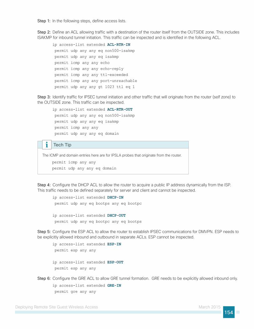
Deploying Remote Site Guest Wireless Access March 2015154
Step 1: In the following steps, define access lists.
Step 2: Define an ACL allowing traffic with a destination of the router itself from the OUTSIDE zone. This includes ISAKMP for inbound tunnel initiation. This traffic can be inspected and is identified in the following ACL.
ip access-list extended ACL-RTR-IN permit udp any any eq non500-isakmp
permit udp any any eq isakmp
permit icmp any any echo
permit icmp any any echo-reply
permit icmp any any ttl-exceeded
permit icmp any any port-unreachable
permit udp any any gt 1023 ttl eq 1
Step 3: Identify traffic for IPSEC tunnel initiation and other traffic that will originate from the router (self zone) to the OUTSIDE zone. This traffic can be inspected.
ip access-list extended ACL-RTR-OUT permit udp any any eq non500-isakmp
permit udp any any eq isakmp
permit icmp any any
permit udp any any eq domain
The ICMP and domain entries here are for IPSLA probes that originate from the router.
permit icmp any any
permit udp any any eq domain
Tech Tip
Step 4: Configure the DHCP ACL to allow the router to acquire a public IP address dynamically from the ISP. This traffic needs to be defined separately for server and client and cannot be inspected.
ip access-list extended DHCP-IN permit udp any eq bootps any eq bootpc
ip access-list extended DHCP-OUT permit udp any eq bootpc any eq bootps
Step 5: Configure the ESP ACL to allow the router to establish IPSEC communications for DMVPN. ESP needs to be explicitly allowed inbound and outbound in separate ACLs. ESP cannot be inspected.
ip access-list extended ESP-IN permit esp any any
ip access-list extended ESP-OUT permit esp any any
Step 6: Configure the GRE ACL to allow GRE tunnel formation. GRE needs to be explicitly allowed inbound only.
ip access-list extended GRE-IN permit gre any any
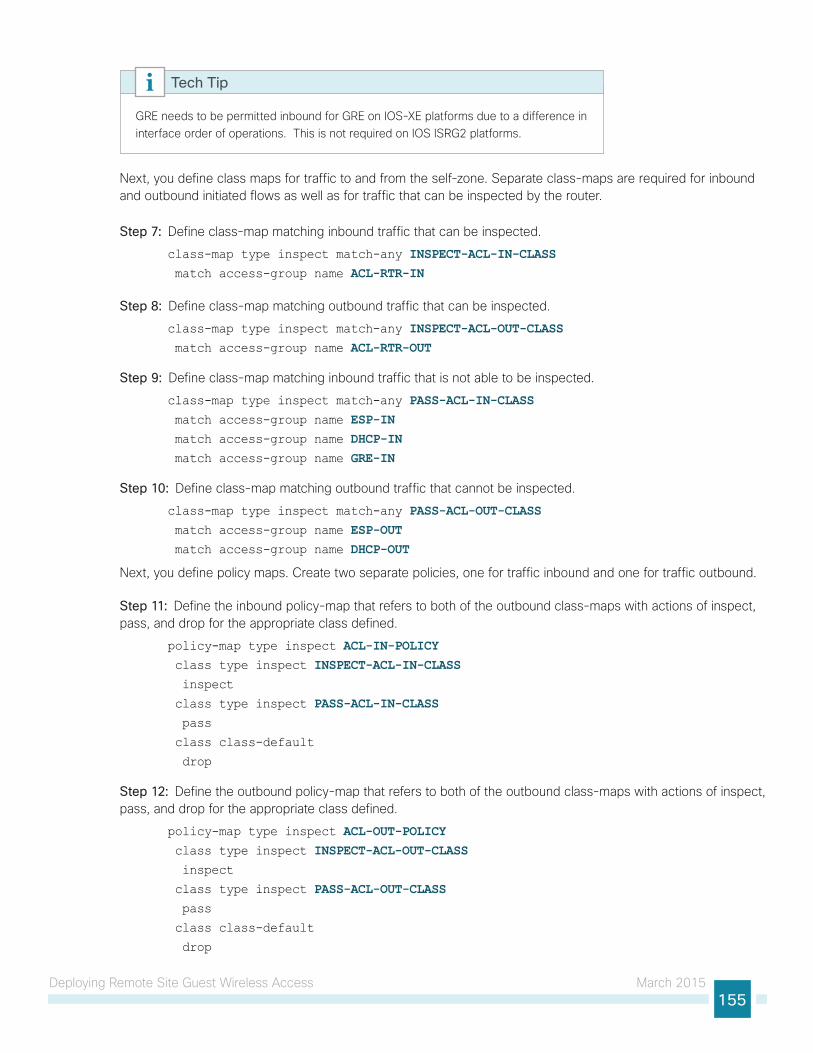
Deploying Remote Site Guest Wireless Access March 2015155
GRE needs to be permitted inbound for GRE on IOS-XE platforms due to a difference in interface order of operations. This is not required on IOS ISRG2 platforms.
Tech Tip
Next, you define class maps for traffic to and from the self-zone. Separate class-maps are required for inbound and outbound initiated flows as well as for traffic that can be inspected by the router.
Step 7: Define class-map matching inbound traffic that can be inspected.
class-map type inspect match-any INSPECT-ACL-IN-CLASS match access-group name ACL-RTR-IN
Step 8: Define class-map matching outbound traffic that can be inspected.
class-map type inspect match-any INSPECT-ACL-OUT-CLASS match access-group name ACL-RTR-OUT
Step 9: Define class-map matching inbound traffic that is not able to be inspected.
class-map type inspect match-any PASS-ACL-IN-CLASS match access-group name ESP-IN match access-group name DHCP-IN match access-group name GRE-IN
Step 10: Define class-map matching outbound traffic that cannot be inspected.
class-map type inspect match-any PASS-ACL-OUT-CLASS match access-group name ESP-OUT match access-group name DHCP-OUT
Next, you define policy maps. Create two separate policies, one for traffic inbound and one for traffic outbound.
Step 11: Define the inbound policy-map that refers to both of the outbound class-maps with actions of inspect, pass, and drop for the appropriate class defined.
policy-map type inspect ACL-IN-POLICY class type inspect INSPECT-ACL-IN-CLASS inspect
class type inspect PASS-ACL-IN-CLASS pass
class class-default
drop
Step 12: Define the outbound policy-map that refers to both of the outbound class-maps with actions of inspect, pass, and drop for the appropriate class defined.
policy-map type inspect ACL-OUT-POLICY class type inspect INSPECT-ACL-OUT-CLASS inspect
class type inspect PASS-ACL-OUT-CLASS pass
class class-default
drop
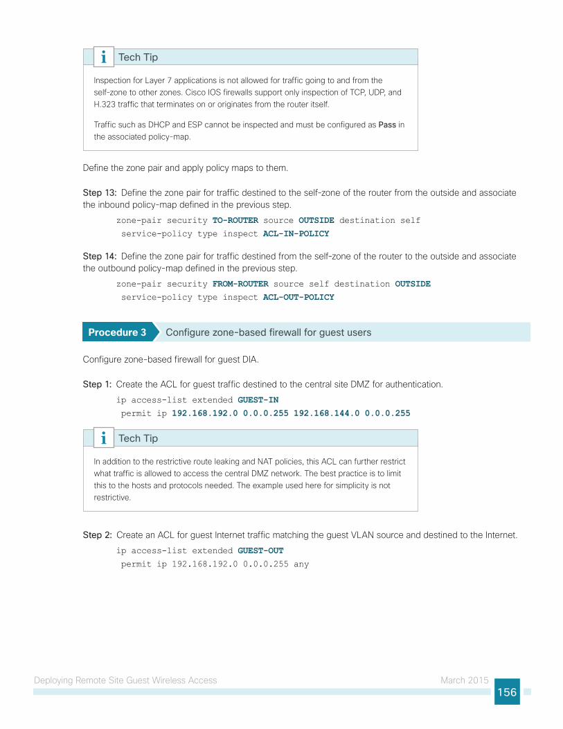
Deploying Remote Site Guest Wireless Access March 2015156
Inspection for Layer 7 applications is not allowed for traffic going to and from the self-zone to other zones. Cisco IOS firewalls support only inspection of TCP, UDP, and H.323 traffic that terminates on or originates from the router itself.
Traffic such as DHCP and ESP cannot be inspected and must be configured as Pass in the associated policy-map.
Tech Tip
Define the zone pair and apply policy maps to them.
Step 13: Define the zone pair for traffic destined to the self-zone of the router from the outside and associate the inbound policy-map defined in the previous step.
zone-pair security TO-ROUTER source OUTSIDE destination self service-policy type inspect ACL-IN-POLICY
Step 14: Define the zone pair for traffic destined from the self-zone of the router to the outside and associate the outbound policy-map defined in the previous step.
zone-pair security FROM-ROUTER source self destination OUTSIDE service-policy type inspect ACL-OUT-POLICY
Procedure 3 Configure zone-based firewall for guest users
Configure zone-based firewall for guest DIA.
Step 1: Create the ACL for guest traffic destined to the central site DMZ for authentication.
ip access-list extended GUEST-IN permit ip 192.168.192.0 0.0.0.255 192.168.144.0 0.0.0.255
In addition to the restrictive route leaking and NAT policies, this ACL can further restrict what traffic is allowed to access the central DMZ network. The best practice is to limit this to the hosts and protocols needed. The example used here for simplicity is not restrictive.
Tech Tip
Step 2: Create an ACL for guest Internet traffic matching the guest VLAN source and destined to the Internet.
ip access-list extended GUEST-OUT permit ip 192.168.192.0 0.0.0.255 any
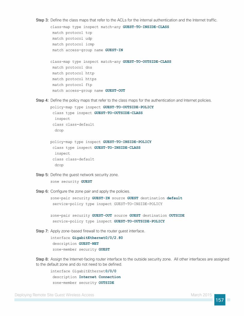
Deploying Remote Site Guest Wireless Access March 2015157
Step 3: Define the class maps that refer to the ACLs for the internal authentication and the Internet traffic.
class-map type inspect match-any GUEST-TO-INSIDE-CLASS match protocol tcp
match protocol udp
match protocol icmp
match access-group name GUEST-IN
class-map type inspect match-any GUEST-TO-OUTSIDE-CLASS match protocol dns
match protocol http
match protocol https
match protocol ftp
match access-group name GUEST-OUT
Step 4: Define the policy maps that refer to the class maps for the authentication and Internet policies.
policy-map type inspect GUEST-TO-OUTSIDE-POLICY class type inspect GUEST-TO-OUTSIDE-CLASS inspect
class class-default
drop
policy-map type inspect GUEST-TO-INSIDE-POLICY class type inspect GUEST-TO-INSIDE-CLASS inspect
class class-default
drop
Step 5: Define the guest network security zone.
zone security GUEST
Step 6: Configure the zone pair and apply the policies.
zone-pair security GUEST-IN source GUEST destination default service-policy type inspect GUEST-TO-INSIDE-POLICY
zone-pair security GUEST-OUT source GUEST destination OUTSIDE service-policy type inspect GUEST-TO-OUTSIDE-POLICY
Step 7: Apply zone-based firewall to the router guest interface.
interface GigabitEthernet0/0/2.80 description GUEST-NET zone-member security GUEST
Step 8: Assign the Internet-facing router interface to the outside security zone. All other interfaces are assigned to the default zone and do not need to be defined.
interface GigabitEthernet0/0/0 description Internet Connection zone-member security OUTSIDE
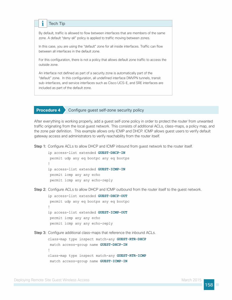
Deploying Remote Site Guest Wireless Access March 2015158
By default, traffic is allowed to flow between interfaces that are members of the same zone. A default “deny-all” policy is applied to traffic moving between zones.
In this case, you are using the “default” zone for all inside interfaces. Traffic can flow between all interfaces in the default zone.
For this configuration, there is not a policy that allows default zone traffic to access the outside zone.
An interface not defined as part of a security zone is automatically part of the “default” zone. In this configuration, all undefined interface DMVPN tunnels, transit sub-interfaces, and service interfaces such as Cisco UCS-E, and SRE interfaces are included as part of the default zone.
Tech Tip
Procedure 4 Configure guest self-zone security policy
After everything is working properly, add a guest self-zone policy in order to protect the router from unwanted traffic originating from the local guest network. This consists of additional ACLs, class-maps, a policy map, and the zone pair definition. This example allows only ICMP and DHCP. ICMP allows guest users to verify default gateway access and administrators to verify reachability from the router itself.
Step 1: Configure ACLs to allow DHCP and ICMP inbound from guest network to the router itself.
ip access-list extended GUEST-DHCP-IN permit udp any eq bootpc any eq bootps
!
ip access-list extended GUEST-ICMP-IN permit icmp any any echo
permit icmp any any echo-reply
Step 2: Configure ACLs to allow DHCP and ICMP outbound from the router itself to the guest network.
ip access-list extended GUEST-DHCP-OUT permit udp any eq bootps any eq bootpc
!
ip access-list extended GUEST-ICMP-OUT permit icmp any any echo
permit icmp any any echo-reply
Step 3: Configure additional class-maps that reference the inbound ACLs.
class-map type inspect match-any GUEST-RTR-DHCP match access-group name GUEST-DHCP-IN!
class-map type inspect match-any GUEST-RTR-ICMP match access-group name GUEST-ICMP-IN
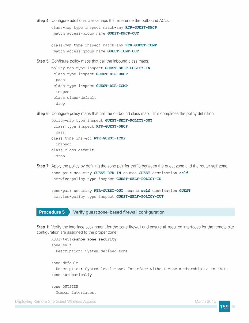
Deploying Remote Site Guest Wireless Access March 2015159
Step 4: Configure additional class-maps that reference the outbound ACLs.
class-map type inspect match-any RTR-GUEST-DHCP match access-group name GUEST-DHCP-OUT
class-map type inspect match-any RTR-GUEST-ICMP match access-group name GUEST-ICMP-OUT
Step 5: Configure policy maps that call the inbound class maps.
policy-map type inspect GUEST-SELF-POLICY-IN class type inspect GUEST-RTR-DHCP pass
class type inspect GUEST-RTR-ICMP inspect
class class-default
drop
Step 6: Configure policy maps that call the outbound class map. This completes the policy definition.
policy-map type inspect GUEST-SELF-POLICY-OUT class type inspect RTR-GUEST-DHCP pass
class type inspect RTR-GUEST-ICMP inspect
class class-default
drop
Step 7: Apply the policy by defining the zone pair for traffic between the guest zone and the router self-zone.
zone-pair security GUEST-RTR-IN source GUEST destination self service-policy type inspect GUEST-SELF-POLICY-IN
zone-pair security RTR-GUEST-OUT source self destination GUEST service-policy type inspect GUEST-SELF-POLICY-OUT
Procedure 5 Verify guest zone-based firewall configuration
Step 1: Verify the interface assignment for the zone firewall and ensure all required interfaces for the remote site configuration are assigned to the proper zone.
RS31-4451X#show zone securityzone self
Description: System defined zone
zone default
Description: System level zone. Interface without zone membership is in this
zone automatically
zone OUTSIDE
Member Interfaces:
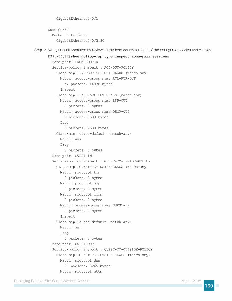
Deploying Remote Site Guest Wireless Access March 2015160
GigabitEthernet0/0/1
zone GUEST
Member Interfaces:
GigabitEthernet0/0/2.80
Step 2: Verify firewall operation by reviewing the byte counts for each of the configured policies and classes.
RS31-4451X#show policy-map type inspect zone-pair sessions Zone-pair: FROM-ROUTER
Service-policy inspect : ACL-OUT-POLICY
Class-map: INSPECT-ACL-OUT-CLASS (match-any)
Match: access-group name ACL-RTR-OUT
52 packets, 14336 bytes
Inspect
Class-map: PASS-ACL-OUT-CLASS (match-any)
Match: access-group name ESP-OUT
0 packets, 0 bytes
Match: access-group name DHCP-OUT
8 packets, 2680 bytes
Pass
8 packets, 2680 bytes
Class-map: class-default (match-any)
Match: any
Drop
0 packets, 0 bytes
Zone-pair: GUEST-IN
Service-policy inspect : GUEST-TO-INSIDE-POLICY
Class-map: GUEST-TO-INSIDE-CLASS (match-any)
Match: protocol tcp
0 packets, 0 bytes
Match: protocol udp
0 packets, 0 bytes
Match: protocol icmp
0 packets, 0 bytes
Match: access-group name GUEST-IN
0 packets, 0 bytes
Inspect
Class-map: class-default (match-any)
Match: any
Drop
0 packets, 0 bytes
Zone-pair: GUEST-OUT
Service-policy inspect : GUEST-TO-OUTSIDE-POLICY
Class-map: GUEST-TO-OUTSIDE-CLASS (match-any)
Match: protocol dns
39 packets, 3265 bytes
Match: protocol http
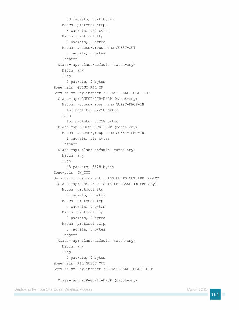
Deploying Remote Site Guest Wireless Access March 2015161
93 packets, 5946 bytes
Match: protocol https
8 packets, 560 bytes
Match: protocol ftp
0 packets, 0 bytes
Match: access-group name GUEST-OUT
0 packets, 0 bytes
Inspect
Class-map: class-default (match-any)
Match: any
Drop
0 packets, 0 bytes
Zone-pair: GUEST-RTR-IN
Service-policy inspect : GUEST-SELF-POLICY-IN
Class-map: GUEST-RTR-DHCP (match-any)
Match: access-group name GUEST-DHCP-IN
151 packets, 52258 bytes
Pass
151 packets, 52258 bytes
Class-map: GUEST-RTR-ICMP (match-any)
Match: access-group name GUEST-ICMP-IN
1 packets, 118 bytes
Inspect
Class-map: class-default (match-any)
Match: any
Drop
68 packets, 6528 bytes
Zone-pair: IN_OUT
Service-policy inspect : INSIDE-TO-OUTSIDE-POLICY
Class-map: INSIDE-TO-OUTSIDE-CLASS (match-any)
Match: protocol ftp
0 packets, 0 bytes
Match: protocol tcp
0 packets, 0 bytes
Match: protocol udp
0 packets, 0 bytes
Match: protocol icmp
0 packets, 0 bytes
Inspect
Class-map: class-default (match-any)
Match: any
Drop
0 packets, 0 bytes
Zone-pair: RTR-GUEST-OUT
Service-policy inspect : GUEST-SELF-POLICY-OUT
Class-map: RTR-GUEST-DHCP (match-any)
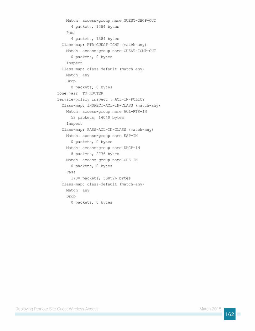
Deploying Remote Site Guest Wireless Access March 2015162
Match: access-group name GUEST-DHCP-OUT
4 packets, 1384 bytes
Pass
4 packets, 1384 bytes
Class-map: RTR-GUEST-ICMP (match-any)
Match: access-group name GUEST-ICMP-OUT
0 packets, 0 bytes
Inspect
Class-map: class-default (match-any)
Match: any
Drop
0 packets, 0 bytes
Zone-pair: TO-ROUTER
Service-policy inspect : ACL-IN-POLICY
Class-map: INSPECT-ACL-IN-CLASS (match-any)
Match: access-group name ACL-RTR-IN
52 packets, 14040 bytes
Inspect
Class-map: PASS-ACL-IN-CLASS (match-any)
Match: access-group name ESP-IN
0 packets, 0 bytes
Match: access-group name DHCP-IN
8 packets, 2736 bytes
Match: access-group name GRE-IN
0 packets, 0 bytes
Pass
1730 packets, 338526 bytes
Class-map: class-default (match-any)
Match: any
Drop
0 packets, 0 bytes
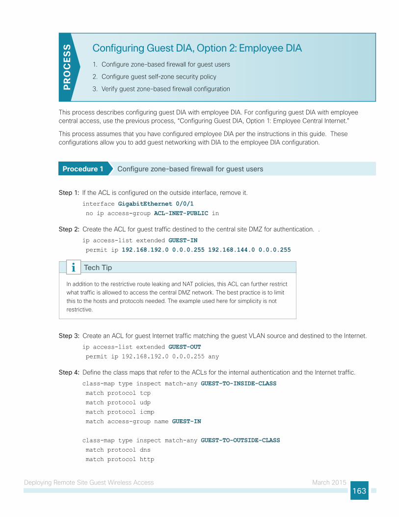
Deploying Remote Site Guest Wireless Access March 2015163
Configuring Guest DIA, Option 2: Employee DIA
1. Configure zone-based firewall for guest users
2. Configure guest self-zone security policy
3. Verify guest zone-based firewall configurationPR
OC
ESS
This process describes configuring guest DIA with employee DIA. For configuring guest DIA with employee central access, use the previous process, “Configuring Guest DIA, Option 1: Employee Central Internet.”
This process assumes that you have configured employee DIA per the instructions in this guide. These configurations allow you to add guest networking with DIA to the employee DIA configuration.
Procedure 1 Configure zone-based firewall for guest users
Step 1: If the ACL is configured on the outside interface, remove it.
interface GigabitEthernet 0/0/1 no ip access-group ACL-INET-PUBLIC in
Step 2: Create the ACL for guest traffic destined to the central site DMZ for authentication. .
ip access-list extended GUEST-IN permit ip 192.168.192.0 0.0.0.255 192.168.144.0 0.0.0.255
In addition to the restrictive route leaking and NAT policies, this ACL can further restrict what traffic is allowed to access the central DMZ network. The best practice is to limit this to the hosts and protocols needed. The example used here for simplicity is not restrictive.
Tech Tip
Step 3: Create an ACL for guest Internet traffic matching the guest VLAN source and destined to the Internet.
ip access-list extended GUEST-OUT permit ip 192.168.192.0 0.0.0.255 any
Step 4: Define the class maps that refer to the ACLs for the internal authentication and the Internet traffic.
class-map type inspect match-any GUEST-TO-INSIDE-CLASS match protocol tcp
match protocol udp
match protocol icmp
match access-group name GUEST-IN
class-map type inspect match-any GUEST-TO-OUTSIDE-CLASS match protocol dns
match protocol http
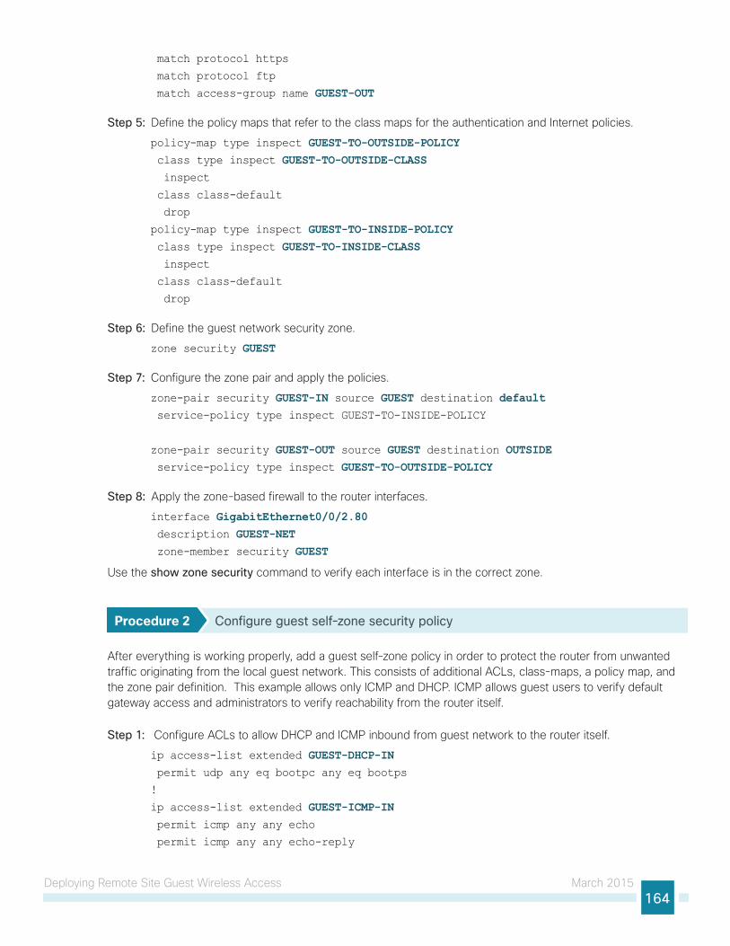
Deploying Remote Site Guest Wireless Access March 2015164
match protocol https
match protocol ftp
match access-group name GUEST-OUT
Step 5: Define the policy maps that refer to the class maps for the authentication and Internet policies.
policy-map type inspect GUEST-TO-OUTSIDE-POLICY class type inspect GUEST-TO-OUTSIDE-CLASS inspect
class class-default
drop
policy-map type inspect GUEST-TO-INSIDE-POLICY class type inspect GUEST-TO-INSIDE-CLASS inspect
class class-default
drop
Step 6: Define the guest network security zone.
zone security GUEST
Step 7: Configure the zone pair and apply the policies.
zone-pair security GUEST-IN source GUEST destination default service-policy type inspect GUEST-TO-INSIDE-POLICY
zone-pair security GUEST-OUT source GUEST destination OUTSIDE service-policy type inspect GUEST-TO-OUTSIDE-POLICY
Step 8: Apply the zone-based firewall to the router interfaces.
interface GigabitEthernet0/0/2.80 description GUEST-NET zone-member security GUEST
Use the show zone security command to verify each interface is in the correct zone.
Procedure 2 Configure guest self-zone security policy
After everything is working properly, add a guest self-zone policy in order to protect the router from unwanted traffic originating from the local guest network. This consists of additional ACLs, class-maps, a policy map, and the zone pair definition. This example allows only ICMP and DHCP. ICMP allows guest users to verify default gateway access and administrators to verify reachability from the router itself.
Step 1: Configure ACLs to allow DHCP and ICMP inbound from guest network to the router itself.
ip access-list extended GUEST-DHCP-IN permit udp any eq bootpc any eq bootps
!
ip access-list extended GUEST-ICMP-IN permit icmp any any echo
permit icmp any any echo-reply
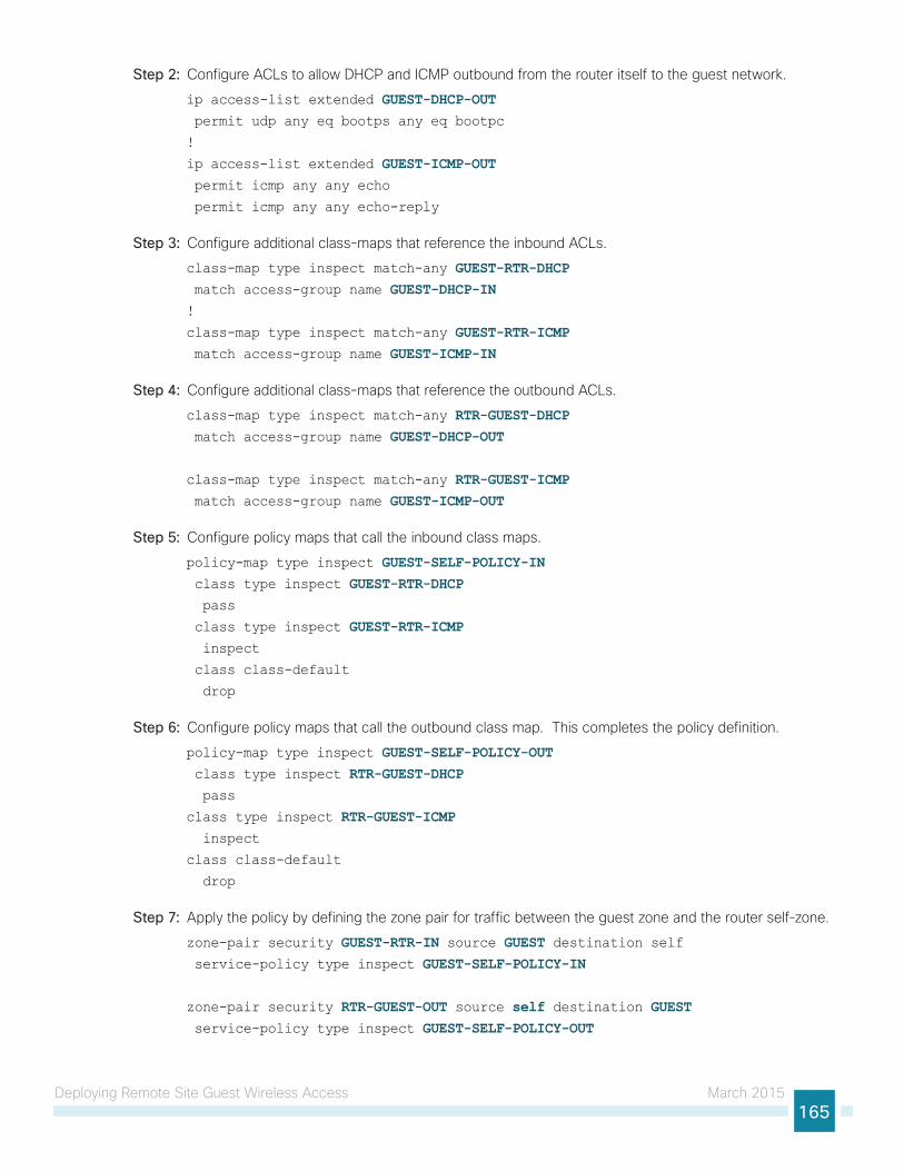
Deploying Remote Site Guest Wireless Access March 2015165
Step 2: Configure ACLs to allow DHCP and ICMP outbound from the router itself to the guest network.
ip access-list extended GUEST-DHCP-OUT permit udp any eq bootps any eq bootpc
!
ip access-list extended GUEST-ICMP-OUT permit icmp any any echo
permit icmp any any echo-reply
Step 3: Configure additional class-maps that reference the inbound ACLs.
class-map type inspect match-any GUEST-RTR-DHCP match access-group name GUEST-DHCP-IN!
class-map type inspect match-any GUEST-RTR-ICMP match access-group name GUEST-ICMP-IN
Step 4: Configure additional class-maps that reference the outbound ACLs.
class-map type inspect match-any RTR-GUEST-DHCP match access-group name GUEST-DHCP-OUT
class-map type inspect match-any RTR-GUEST-ICMP match access-group name GUEST-ICMP-OUT
Step 5: Configure policy maps that call the inbound class maps.
policy-map type inspect GUEST-SELF-POLICY-IN class type inspect GUEST-RTR-DHCP pass
class type inspect GUEST-RTR-ICMP inspect
class class-default
drop
Step 6: Configure policy maps that call the outbound class map. This completes the policy definition.
policy-map type inspect GUEST-SELF-POLICY-OUT class type inspect RTR-GUEST-DHCP pass
class type inspect RTR-GUEST-ICMP inspect
class class-default
drop
Step 7: Apply the policy by defining the zone pair for traffic between the guest zone and the router self-zone.
zone-pair security GUEST-RTR-IN source GUEST destination self service-policy type inspect GUEST-SELF-POLICY-IN
zone-pair security RTR-GUEST-OUT source self destination GUEST service-policy type inspect GUEST-SELF-POLICY-OUT
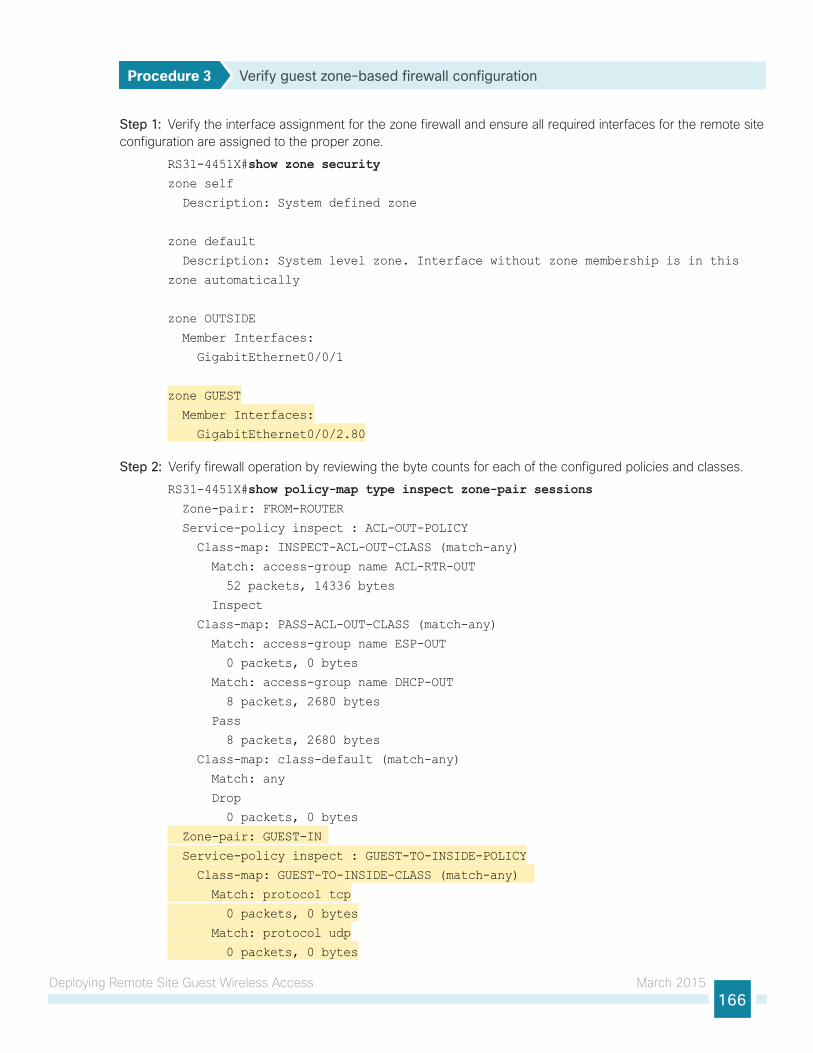
Deploying Remote Site Guest Wireless Access March 2015166
Procedure 3 Verify guest zone-based firewall configuration
Step 1: Verify the interface assignment for the zone firewall and ensure all required interfaces for the remote site configuration are assigned to the proper zone.
RS31-4451X#show zone securityzone self
Description: System defined zone
zone default
Description: System level zone. Interface without zone membership is in this
zone automatically
zone OUTSIDE
Member Interfaces:
GigabitEthernet0/0/1
zone GUEST
Member Interfaces:
GigabitEthernet0/0/2.80
Step 2: Verify firewall operation by reviewing the byte counts for each of the configured policies and classes.
RS31-4451X#show policy-map type inspect zone-pair sessions Zone-pair: FROM-ROUTER
Service-policy inspect : ACL-OUT-POLICY
Class-map: INSPECT-ACL-OUT-CLASS (match-any)
Match: access-group name ACL-RTR-OUT
52 packets, 14336 bytes
Inspect
Class-map: PASS-ACL-OUT-CLASS (match-any)
Match: access-group name ESP-OUT
0 packets, 0 bytes
Match: access-group name DHCP-OUT
8 packets, 2680 bytes
Pass
8 packets, 2680 bytes
Class-map: class-default (match-any)
Match: any
Drop
0 packets, 0 bytes
Zone-pair: GUEST-IN
Service-policy inspect : GUEST-TO-INSIDE-POLICY
Class-map: GUEST-TO-INSIDE-CLASS (match-any)
Match: protocol tcp
0 packets, 0 bytes
Match: protocol udp
0 packets, 0 bytes

Deploying Remote Site Guest Wireless Access March 2015167
Match: protocol icmp
0 packets, 0 bytes
Match: access-group name GUEST-IN
0 packets, 0 bytes
Inspect
Class-map: class-default (match-any)
Match: any
Drop
0 packets, 0 bytes
Zone-pair: GUEST-OUT
Service-policy inspect : GUEST-TO-OUTSIDE-POLICY
Class-map: GUEST-TO-OUTSIDE-CLASS (match-any)
Match: protocol dns
39 packets, 3265 bytes
Match: protocol http
93 packets, 5946 bytes
Match: protocol https
8 packets, 560 bytes
Match: protocol ftp
0 packets, 0 bytes
Match: access-group name GUEST-OUT
0 packets, 0 bytes
Inspect
Class-map: class-default (match-any)
Match: any
Drop
0 packets, 0 bytes
Zone-pair: GUEST-RTR-IN
Service-policy inspect : GUEST-SELF-POLICY-IN
Class-map: GUEST-RTR-DHCP (match-any)
Match: access-group name GUEST-DHCP-IN
151 packets, 52258 bytes
Pass
151 packets, 52258 bytes
Class-map: GUEST-RTR-ICMP (match-any)
Match: access-group name GUEST-ICMP-IN
1 packets, 118 bytes
Inspect
Class-map: class-default (match-any)
Match: any
Drop
68 packets, 6528 bytes
Zone-pair: IN_OUT
Service-policy inspect : INSIDE-TO-OUTSIDE-POLICY
Class-map: INSIDE-TO-OUTSIDE-CLASS (match-any)
Match: protocol ftp
0 packets, 0 bytes
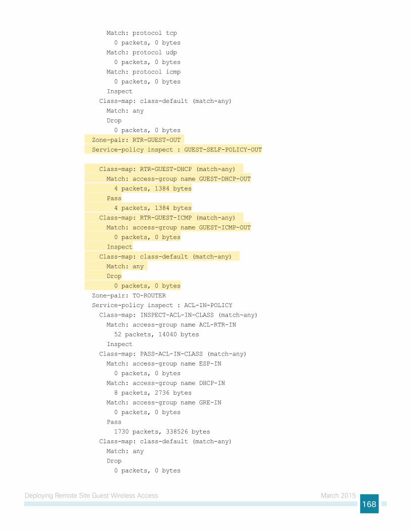
Deploying Remote Site Guest Wireless Access March 2015168
Match: protocol tcp
0 packets, 0 bytes
Match: protocol udp
0 packets, 0 bytes
Match: protocol icmp
0 packets, 0 bytes
Inspect
Class-map: class-default (match-any)
Match: any
Drop
0 packets, 0 bytes
Zone-pair: RTR-GUEST-OUT
Service-policy inspect : GUEST-SELF-POLICY-OUT
Class-map: RTR-GUEST-DHCP (match-any)
Match: access-group name GUEST-DHCP-OUT
4 packets, 1384 bytes
Pass
4 packets, 1384 bytes
Class-map: RTR-GUEST-ICMP (match-any)
Match: access-group name GUEST-ICMP-OUT
0 packets, 0 bytes
Inspect
Class-map: class-default (match-any)
Match: any
Drop
0 packets, 0 bytes
Zone-pair: TO-ROUTER
Service-policy inspect : ACL-IN-POLICY
Class-map: INSPECT-ACL-IN-CLASS (match-any)
Match: access-group name ACL-RTR-IN
52 packets, 14040 bytes
Inspect
Class-map: PASS-ACL-IN-CLASS (match-any)
Match: access-group name ESP-IN
0 packets, 0 bytes
Match: access-group name DHCP-IN
8 packets, 2736 bytes
Match: access-group name GRE-IN
0 packets, 0 bytes
Pass
1730 packets, 338526 bytes
Class-map: class-default (match-any)
Match: any
Drop
0 packets, 0 bytes
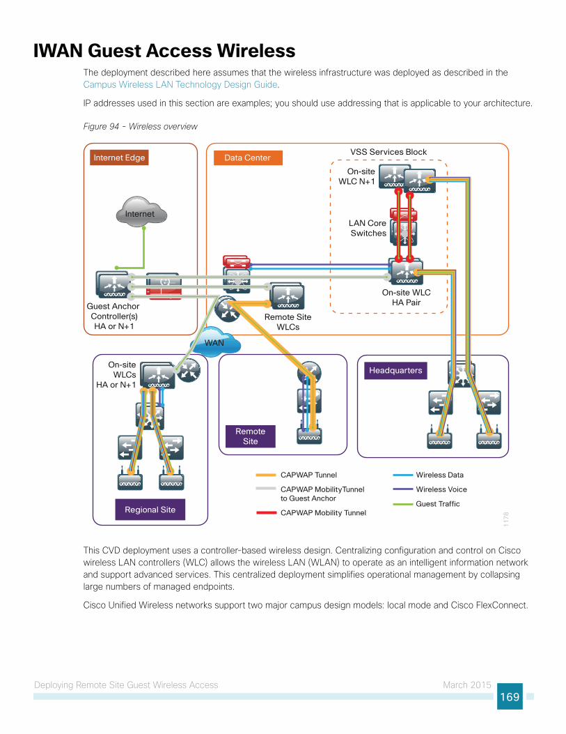
Deploying Remote Site Guest Wireless Access March 2015169
IWAN Guest Access WirelessThe deployment described here assumes that the wireless infrastructure was deployed as described in the Campus Wireless LAN Technology Design Guide.
IP addresses used in this section are examples; you should use addressing that is applicable to your architecture.
Figure 94 - Wireless overview
VSS Services Block
On-site WLCHA Pair
On-siteWLC N+1
WAN
RemoteSite
LAN CoreSwitches
11
78Regional Site
Internet Edge Data Center
Headquarters
Internet
Remote SiteWLCs
On-siteWLCs
HA or N+1
Guest Anchor Controller(s)HA or N+1
CAPWAP Tunnel
CAPWAP MobilityTunnel to Guest Anchor
CAPWAP Mobility Tunnel
Wireless Data
Wireless Voice
Guest Traffic
This CVD deployment uses a controller-based wireless design. Centralizing configuration and control on Cisco wireless LAN controllers (WLC) allows the wireless LAN (WLAN) to operate as an intelligent information network and support advanced services. This centralized deployment simplifies operational management by collapsing large numbers of managed endpoints.
Cisco Unified Wireless networks support two major campus design models: local mode and Cisco FlexConnect.
Deploying Remote Site Guest Wireless Access March 2015170
In a local-mode design model, the wireless LAN controller and access points are co-located. The wireless LAN controller can be connected to a data center services block as described in the Campus Wireless LAN Technology Design Guide or can be connected to a LAN distribution layer at the site. Wireless traffic between wireless LAN clients and the LAN is tunneled by using the control and provisioning of wireless access points (CAPWAP) protocol between the controller and the access point.
A local-mode architecture uses the controller as a single point for managing Layer 2 security and wireless network policies. It also enables services to be applied to wired and wireless traffic in a consistent and coordinated fashion. This controller can be a standalone controller like the Cisco 2500 Series Wireless LAN Controller or it can be embedded in the access switch like the Cisco Catalyst 3850 Series Switch.
Cisco FlexConnect is a wireless solution for remote-site deployments. It enables organizations to configure and control remote-site access points from the headquarters through the WAN, without deploying a controller in each remote site.
If all of the following are true at a site, deploy Cisco FlexConnect at the site:
• The site LAN is a single access-layer switch or switch stack.
• The site has fewer than 50 access points.
• The site has a WAN latency less than 100 ms round-trip to the shared controller.
The Cisco FlexConnect access point can switch client data traffic out its local wired interface and can use 802.1Q trunking in order to segment multiple WLANs. The trunk’s native VLAN is used for all CAPWAP communication between the access point and the controller. This mode of operation is referred to as FlexConnect local switching and is the mode of operation described in this guide.
The other mode of operation, which is not discussed in this guide, is called FlexConnect centrally switched. In this mode, a majority of the traffic is tunneled back to the centrally located WLC, allowing the administrator to configure access control lists (ACLs) to selectively switch some local traffic.
There are two methods for deploying a guest portal described in this guide. The first is local web authentication (LWA). With LWA, the WLC provides the guest portal and guests are redirected to this portal for authentication when they attempt to use a browser. For LWA, each controller that supports guest users will need to have the portal configured.
The second method is centralized web authentication (CWA). With CWA, the guest portal is provided by a Cisco ISE that is deployed at a centralized location and used by multiple controllers.
There are several methods for deploying guest wireless at a remote site that were tested:
• Guest access with an acceptable use policy and no authentication
• Guest access using LWA with the guest user defined in the local database
• Guest access using LWA with the guest user defined on a centralized authentication server
• Guest access using CWA with the ISE server deployed in the data center at the central site
• Guest access using CWA with the ISE server deployed in a DMZ at the central site
In this guide, the deployments documented are LWA using a local database and CWA using ISE in the DMZ.
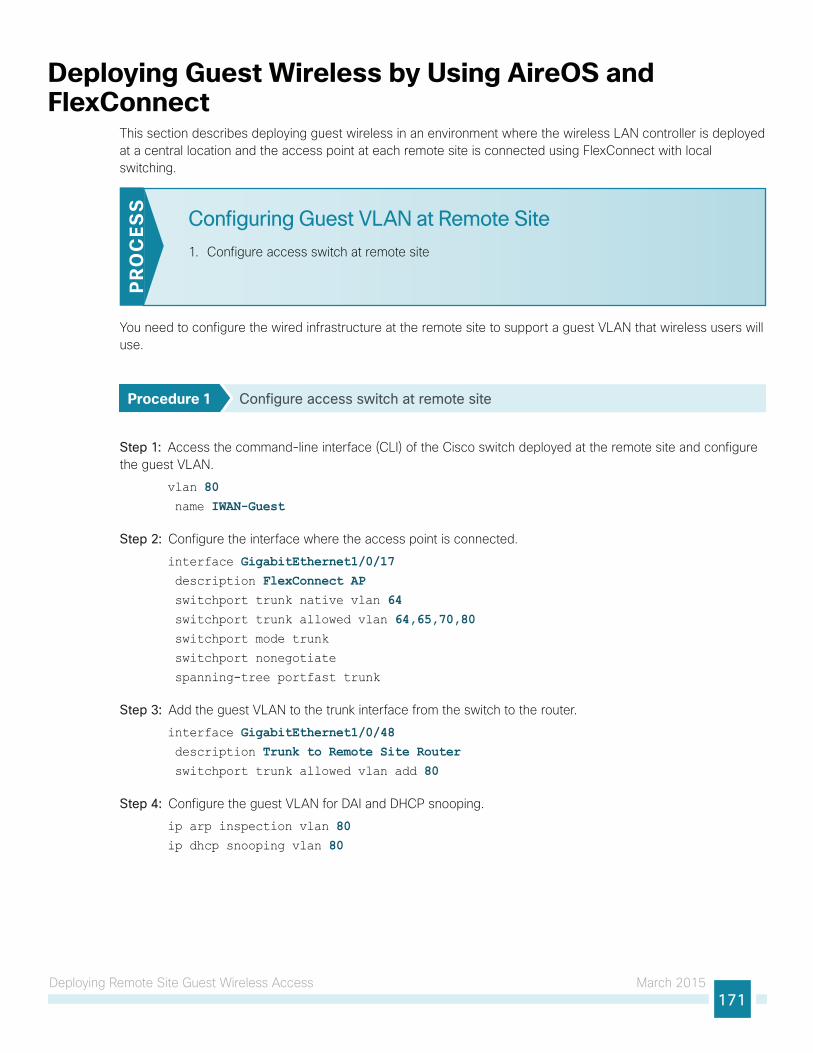
Deploying Remote Site Guest Wireless Access March 2015171
Deploying Guest Wireless by Using AireOS and FlexConnect
This section describes deploying guest wireless in an environment where the wireless LAN controller is deployed at a central location and the access point at each remote site is connected using FlexConnect with local switching.
Configuring Guest VLAN at Remote Site
1. Configure access switch at remote site
PR
OC
ESS
You need to configure the wired infrastructure at the remote site to support a guest VLAN that wireless users will use.
Procedure 1 Configure access switch at remote site
Step 1: Access the command-line interface (CLI) of the Cisco switch deployed at the remote site and configure the guest VLAN.
vlan 80 name IWAN-Guest
Step 2: Configure the interface where the access point is connected.
interface GigabitEthernet1/0/17 description FlexConnect AP switchport trunk native vlan 64 switchport trunk allowed vlan 64,65,70,80 switchport mode trunk
switchport nonegotiate
spanning-tree portfast trunk
Step 3: Add the guest VLAN to the trunk interface from the switch to the router.
interface GigabitEthernet1/0/48 description Trunk to Remote Site Router switchport trunk allowed vlan add 80
Step 4: Configure the guest VLAN for DAI and DHCP snooping.
ip arp inspection vlan 80ip dhcp snooping vlan 80
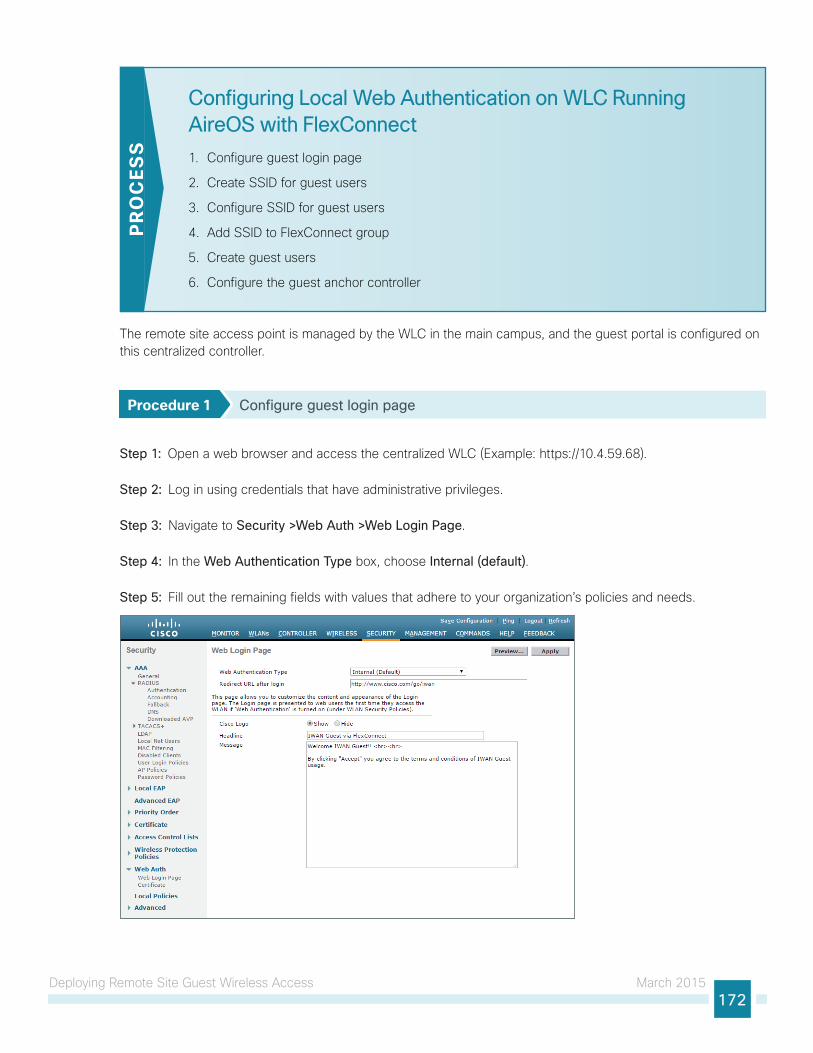
Deploying Remote Site Guest Wireless Access March 2015172
Configuring Local Web Authentication on WLC Running AireOS with FlexConnect
1. Configure guest login page
2. Create SSID for guest users
3. Configure SSID for guest users
4. Add SSID to FlexConnect group
5. Create guest users
6. Configure the guest anchor controller
PR
OC
ESS
The remote site access point is managed by the WLC in the main campus, and the guest portal is configured on this centralized controller.
Procedure 1 Configure guest login page
Step 1: Open a web browser and access the centralized WLC (Example: https://10.4.59.68).
Step 2: Log in using credentials that have administrative privileges.
Step 3: Navigate to Security >Web Auth >Web Login Page.
Step 4: In the Web Authentication Type box, choose Internal (default).
Step 5: Fill out the remaining fields with values that adhere to your organization’s policies and needs.
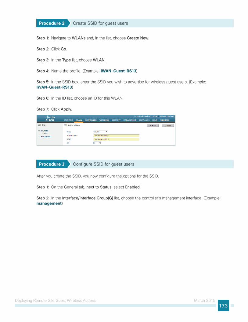
Deploying Remote Site Guest Wireless Access March 2015173
Procedure 2 Create SSID for guest users
Step 1: Navigate to WLANs and, in the list, choose Create New.
Step 2: Click Go.
Step 3: In the Type list, choose WLAN.
Step 4: Name the profile. (Example: IWAN-Guest-RS13)
Step 5: In the SSID box, enter the SSID you wish to advertise for wireless guest users. (Example: IWAN-Guest-RS13)
Step 6: In the ID list, choose an ID for this WLAN.
Step 7: Click Apply.
Procedure 3 Configure SSID for guest users
After you create the SSID, you now configure the options for the SSID.
Step 1: On the General tab, next to Status, select Enabled.
Step 2: In the Interface/Interface Group(G) list, choose the controller’s management interface. (Example: management)
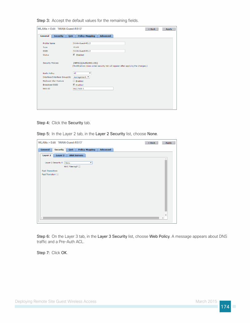
Deploying Remote Site Guest Wireless Access March 2015174
Step 3: Accept the default values for the remaining fields.
Step 4: Click the Security tab.
Step 5: In the Layer 2 tab, in the Layer 2 Security list, choose None.
Step 6: On the Layer 3 tab, in the Layer 3 Security list, choose Web Policy. A message appears about DNS traffic and a Pre-Auth ACL.
Step 7: Click OK.
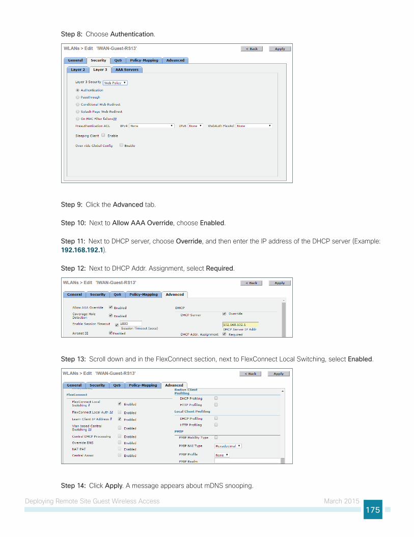
Deploying Remote Site Guest Wireless Access March 2015175
Step 8: Choose Authentication.
Step 9: Click the Advanced tab.
Step 10: Next to Allow AAA Override, choose Enabled.
Step 11: Next to DHCP server, choose Override, and then enter the IP address of the DHCP server (Example: 192.168.192.1).
Step 12: Next to DHCP Addr. Assignment, select Required.
Step 13: Scroll down and in the FlexConnect section, next to FlexConnect Local Switching, select Enabled.
Step 14: Click Apply. A message appears about mDNS snooping.
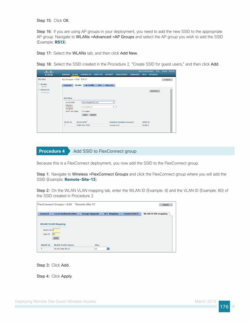
Deploying Remote Site Guest Wireless Access March 2015176
Step 15: Click OK.
Step 16: If you are using AP groups in your deployment, you need to add the new SSID to the appropriate AP group. Navigate to WLANs >Advanced >AP Groups and select the AP group you wish to add the SSID (Example: RS13).
Step 17: Select the WLANs tab, and then click Add New.
Step 18: Select the SSID created in the Procedure 2, “Create SSID for guest users,” and then click Add.
Procedure 4 Add SSID to FlexConnect group
Because this is a FlexConnect deployment, you now add the SSID to the FlexConnect group.
Step 1: Navigate to Wireless >FlexConnect Groups and click the FlexConnect group where you will add the SSID (Example: Remote-Site-13).
Step 2: On the WLAN VLAN mapping tab, enter the WLAN ID (Example: 8) and the VLAN ID (Example: 80) of the SSID created in Procedure 2.
Step 3: Click Add.
Step 4: Click Apply.
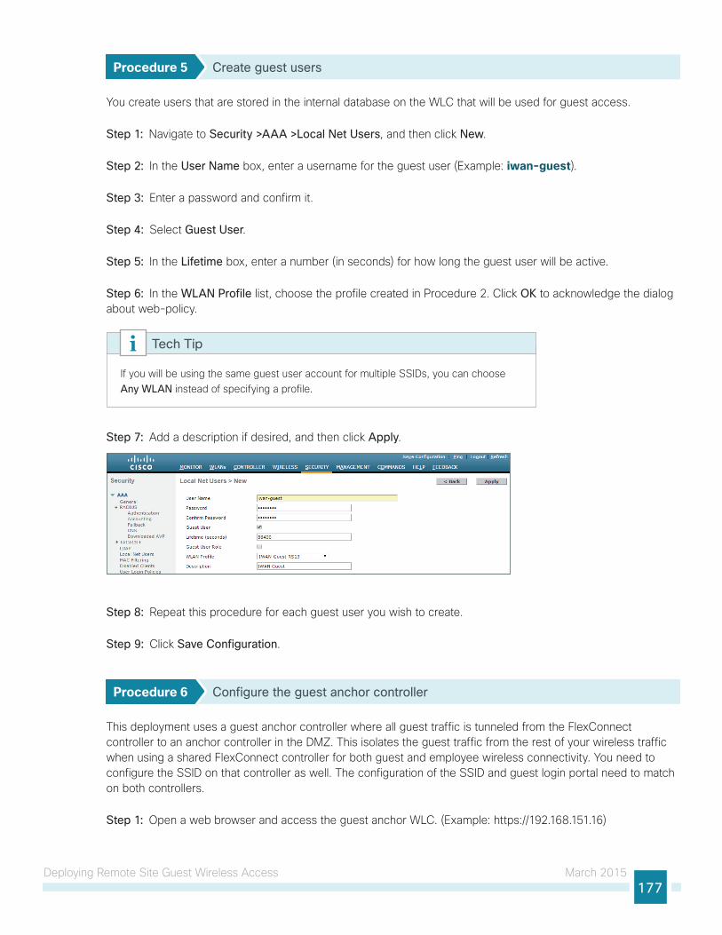
Deploying Remote Site Guest Wireless Access March 2015177
Procedure 5 Create guest users
You create users that are stored in the internal database on the WLC that will be used for guest access.
Step 1: Navigate to Security >AAA >Local Net Users, and then click New.
Step 2: In the User Name box, enter a username for the guest user (Example: iwan-guest).
Step 3: Enter a password and confirm it.
Step 4: Select Guest User.
Step 5: In the Lifetime box, enter a number (in seconds) for how long the guest user will be active.
Step 6: In the WLAN Profile list, choose the profile created in Procedure 2. Click OK to acknowledge the dialog about web-policy.
If you will be using the same guest user account for multiple SSIDs, you can choose Any WLAN instead of specifying a profile.
Tech Tip
Step 7: Add a description if desired, and then click Apply.
Step 8: Repeat this procedure for each guest user you wish to create.
Step 9: Click Save Configuration.
Procedure 6 Configure the guest anchor controller
This deployment uses a guest anchor controller where all guest traffic is tunneled from the FlexConnect controller to an anchor controller in the DMZ. This isolates the guest traffic from the rest of your wireless traffic when using a shared FlexConnect controller for both guest and employee wireless connectivity. You need to configure the SSID on that controller as well. The configuration of the SSID and guest login portal need to match on both controllers.
Step 1: Open a web browser and access the guest anchor WLC. (Example: https://192.168.151.16)
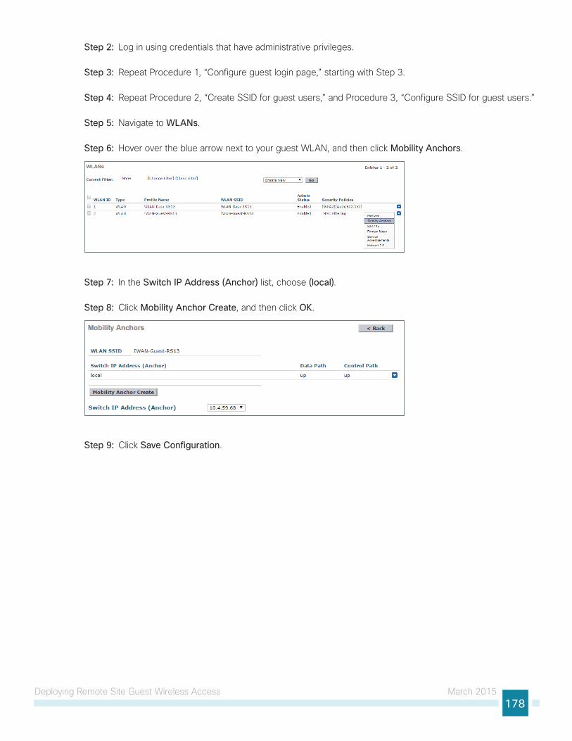
Deploying Remote Site Guest Wireless Access March 2015178
Step 2: Log in using credentials that have administrative privileges.
Step 3: Repeat Procedure 1, “Configure guest login page,” starting with Step 3.
Step 4: Repeat Procedure 2, “Create SSID for guest users,” and Procedure 3, “Configure SSID for guest users.”
Step 5: Navigate to WLANs.
Step 6: Hover over the blue arrow next to your guest WLAN, and then click Mobility Anchors.
Step 7: In the Switch IP Address (Anchor) list, choose (local).
Step 8: Click Mobility Anchor Create, and then click OK.
Step 9: Click Save Configuration.
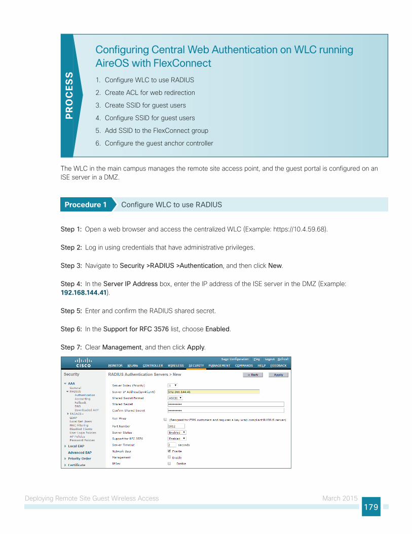
Deploying Remote Site Guest Wireless Access March 2015179
Configuring Central Web Authentication on WLC running AireOS with FlexConnect
1. Configure WLC to use RADIUS
2. Create ACL for web redirection
3. Create SSID for guest users
4. Configure SSID for guest users
5. Add SSID to the FlexConnect group
6. Configure the guest anchor controller
PR
OC
ESS
The WLC in the main campus manages the remote site access point, and the guest portal is configured on an ISE server in a DMZ.
Procedure 1 Configure WLC to use RADIUS
Step 1: Open a web browser and access the centralized WLC (Example: https://10.4.59.68).
Step 2: Log in using credentials that have administrative privileges.
Step 3: Navigate to Security >RADIUS >Authentication, and then click New.
Step 4: In the Server IP Address box, enter the IP address of the ISE server in the DMZ (Example: 192.168.144.41).
Step 5: Enter and confirm the RADIUS shared secret.
Step 6: In the Support for RFC 3576 list, choose Enabled.
Step 7: Clear Management, and then click Apply.
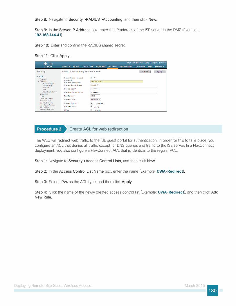
Deploying Remote Site Guest Wireless Access March 2015180
Step 8: Navigate to Security >RADIUS >Accounting, and then click New.
Step 9: In the Server IP Address box, enter the IP address of the ISE server in the DMZ (Example: 192.168.144.41).
Step 10: Enter and confirm the RADIUS shared secret.
Step 11: Click Apply.
Procedure 2 Create ACL for web redirection
The WLC will redirect web traffic to the ISE guest portal for authentication. In order for this to take place, you configure an ACL that denies all traffic except for DNS queries and traffic to the ISE server. In a FlexConnect deployment, you also configure a FlexConnect ACL that is identical to the regular ACL.
Step 1: Navigate to Security >Access Control Lists, and then click New.
Step 2: In the Access Control List Name box, enter the name (Example: CWA-Redirect).
Step 3: Select IPv4 as the ACL type, and then click Apply.
Step 4: Click the name of the newly created access control list (Example: CWA-Redirect), and then click Add New Rule.
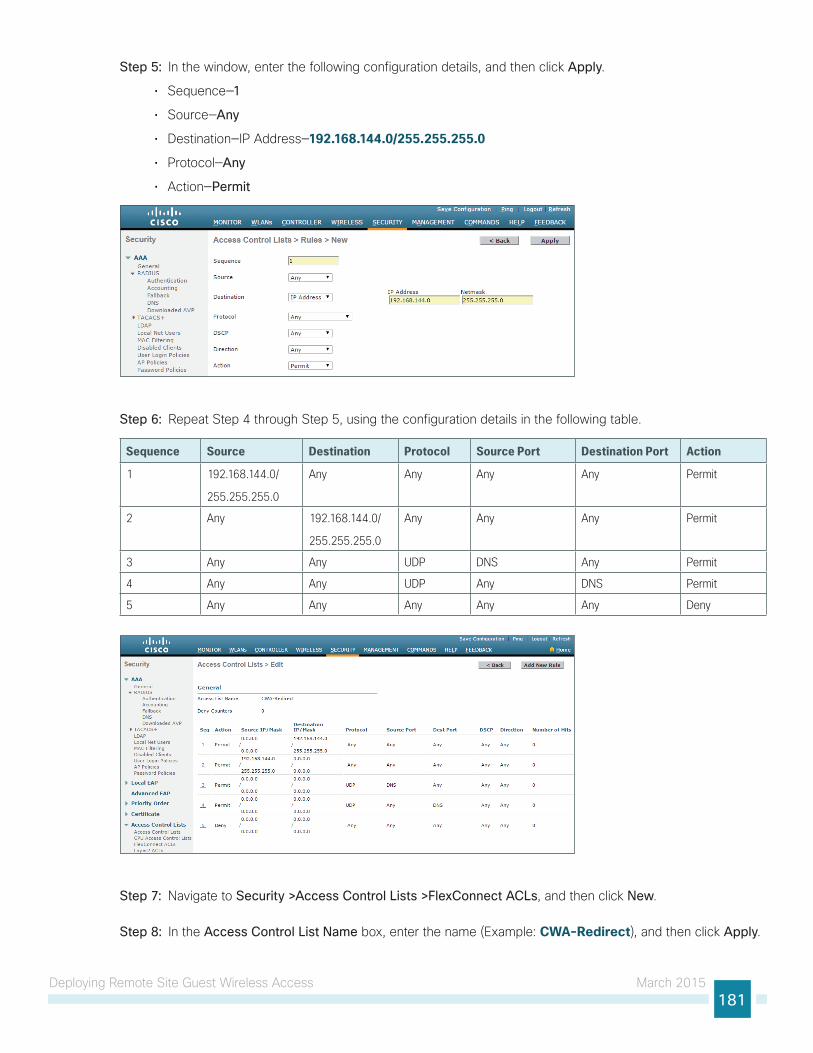
Deploying Remote Site Guest Wireless Access March 2015181
Step 5: In the window, enter the following configuration details, and then click Apply.
• Sequence—1
• Source—Any
• Destination—IP Address—192.168.144.0/255.255.255.0
• Protocol—Any
• Action—Permit
Step 6: Repeat Step 4 through Step 5, using the configuration details in the following table.
Sequence Source Destination Protocol Source Port Destination Port Action
1 192.168.144.0/
255.255.255.0
Any Any Any Any Permit
2 Any 192.168.144.0/
255.255.255.0
Any Any Any Permit
3 Any Any UDP DNS Any Permit
4 Any Any UDP Any DNS Permit
5 Any Any Any Any Any Deny
Step 7: Navigate to Security >Access Control Lists >FlexConnect ACLs, and then click New.
Step 8: In the Access Control List Name box, enter the name (Example: CWA-Redirect), and then click Apply.
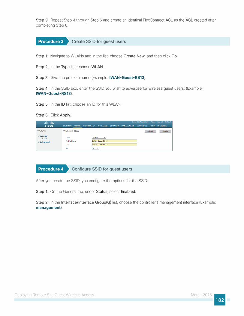
Deploying Remote Site Guest Wireless Access March 2015182
Step 9: Repeat Step 4 through Step 6 and create an identical FlexConnect ACL as the ACL created after completing Step 6.
Procedure 3 Create SSID for guest users
Step 1: Navigate to WLANs and in the list, choose Create New, and then click Go.
Step 2: In the Type list, choose WLAN.
Step 3: Give the profile a name (Example: IWAN-Guest-RS13).
Step 4: In the SSID box, enter the SSID you wish to advertise for wireless guest users. (Example: IWAN-Guest-RS13).
Step 5: In the ID list, choose an ID for this WLAN.
Step 6: Click Apply.
Procedure 4 Configure SSID for guest users
After you create the SSID, you configure the options for the SSID.
Step 1: On the General tab, under Status, select Enabled.
Step 2: In the Interface/Interface Group(G) list, choose the controller’s management interface (Example: management).
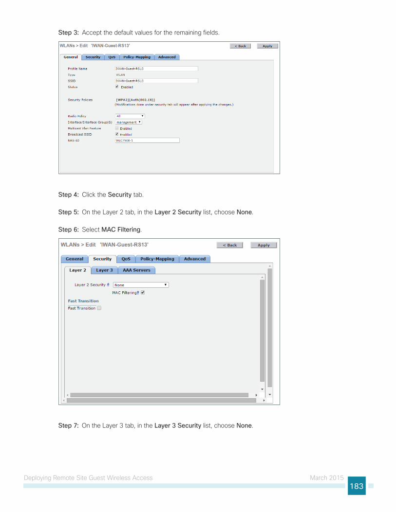
Deploying Remote Site Guest Wireless Access March 2015183
Step 3: Accept the default values for the remaining fields.
Step 4: Click the Security tab.
Step 5: On the Layer 2 tab, in the Layer 2 Security list, choose None.
Step 6: Select MAC Filtering.
Step 7: On the Layer 3 tab, in the Layer 3 Security list, choose None.
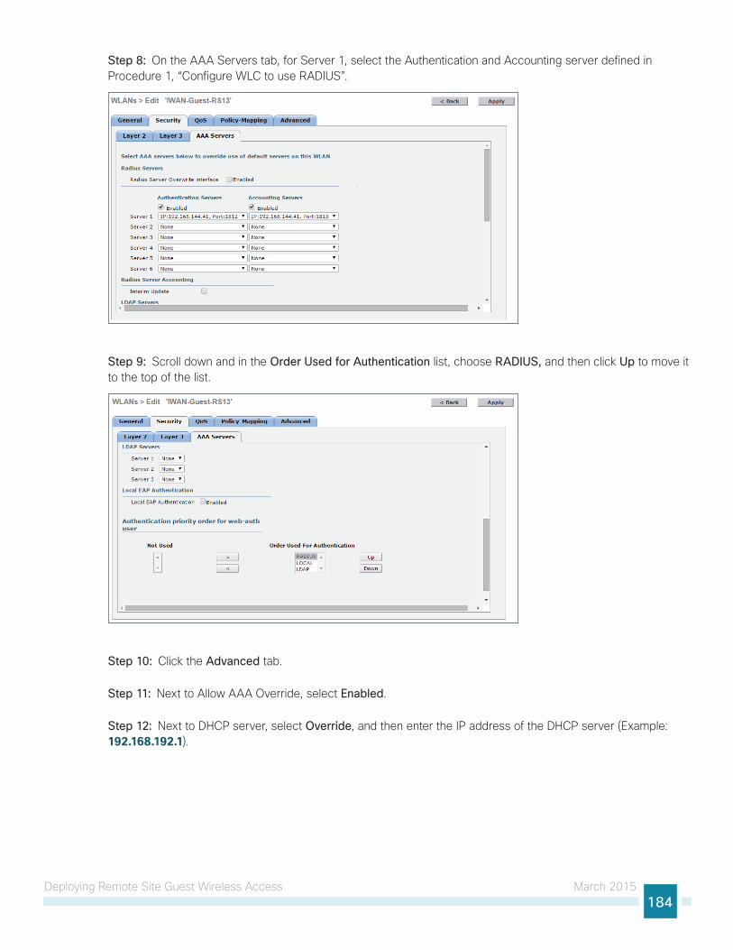
Deploying Remote Site Guest Wireless Access March 2015184
Step 8: On the AAA Servers tab, for Server 1, select the Authentication and Accounting server defined in Procedure 1, “Configure WLC to use RADIUS”.
Step 9: Scroll down and in the Order Used for Authentication list, choose RADIUS, and then click Up to move it to the top of the list.
Step 10: Click the Advanced tab.
Step 11: Next to Allow AAA Override, select Enabled.
Step 12: Next to DHCP server, select Override, and then enter the IP address of the DHCP server (Example: 192.168.192.1).
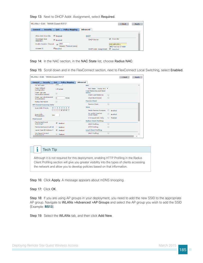
Deploying Remote Site Guest Wireless Access March 2015185
Step 13: Next to DHCP Addr. Assignment, select Required.
Step 14: In the NAC section, in the NAC State list, choose Radius NAC.
Step 15: Scroll down and in the FlexConnect section, next to FlexConnect Local Switching, select Enabled.
Although it is not required for this deployment, enabling HTTP Profiling in the Radius Client Profiling section will give you greater visibility into the types of clients accessing the network and allow you to develop policies based on that information.
Tech Tip
Step 16: Click Apply. A message appears about mDNS snooping.
Step 17: Click OK.
Step 18: If you are using AP groups in your deployment, you need to add the new SSID to the appropriate AP group. Navigate to WLANs >Advanced >AP Groups and select the AP group you wish to add the SSID (Example: RS13).
Step 19: Select the WLANs tab, and then click Add New.
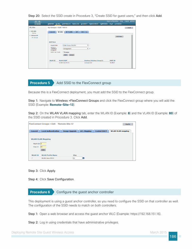
Deploying Remote Site Guest Wireless Access March 2015186
Step 20: Select the SSID create in Procedure 3, “Create SSID for guest users,” and then click Add.
Procedure 5 Add SSID to the FlexConnect group
Because this is a FlexConnect deployment, you must add the SSID to the FlexConnect group.
Step 1: Navigate to Wireless >FlexConnect Groups and click the FlexConnect group where you will add the SSID (Example: Remote-Site-13).
Step 2: On the WLAN VLAN mapping tab, enter the WLAN ID (Example: 8) and the VLAN ID (Example: 80) of the SSID created in Procedure 3. Click Add.
Step 3: Click Apply.
Step 4: Click Save Configuration.
Procedure 6 Configure the guest anchor controller
This deployment is using a guest anchor controller, so you need to configure the SSID on that controller as well. The configuration of the SSID needs to match on both controllers.
Step 1: Open a web browser and access the guest anchor WLC (Example: https://192.168.151.16).
Step 2: Log in using credentials that have administrative privileges.
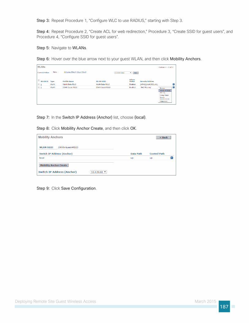
Deploying Remote Site Guest Wireless Access March 2015187
Step 3: Repeat Procedure 1, “Configure WLC to use RADIUS,” starting with Step 3.
Step 4: Repeat Procedure 2, “Create ACL for web redirection,” Procedure 3, “Create SSID for guest users”, and Procedure 4, “Configure SSID for guest users”.
Step 5: Navigate to WLANs.
Step 6: Hover over the blue arrow next to your guest WLAN, and then click Mobility Anchors.
Step 7: In the Switch IP Address (Anchor) list, choose (local).
Step 8: Click Mobility Anchor Create, and then click OK.
Step 9: Click Save Configuration.
Deploying Remote Site Guest Wireless Access March 2015188
Guest Wireless Using Local Controller with AireOSThis section describes the steps required to deploy guest wireless in an environment where the wireless LAN controller is deployed at the remote site running AireOS.
Configuring Local Web Authentication on Remote WLC Running AireOS
1. Configure guest login page
2. Create guest interface
3. Create SSID for guest users
4. Configure SSID for guest users
5. Create guest users
PR
OC
ESS
The WLC manages the remote site access point located at the remote site, and the guest portal is configured on this local controller.
Procedure 1 Configure guest login page
Step 1: Open a web browser and access the local WLC (Example: https://10.7.199.16).
Step 2: Log in using credentials that have administrative privileges.
Step 3: Navigate to Security >Web Auth >Web Login Page.
Step 4: In the Web Authentication Type list, choose Internal (default).
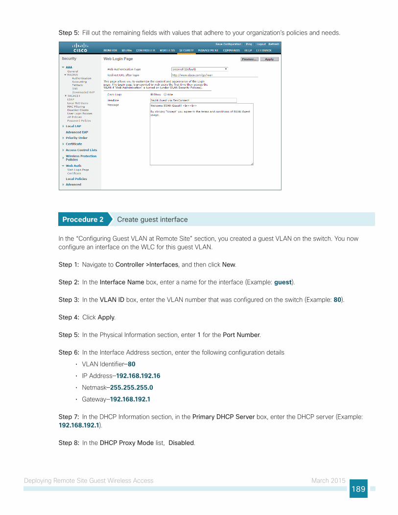
Deploying Remote Site Guest Wireless Access March 2015189
Step 5: Fill out the remaining fields with values that adhere to your organization’s policies and needs.
Procedure 2 Create guest interface
In the “Configuring Guest VLAN at Remote Site” section, you created a guest VLAN on the switch. You now configure an interface on the WLC for this guest VLAN.
Step 1: Navigate to Controller >Interfaces, and then click New.
Step 2: In the Interface Name box, enter a name for the interface (Example: guest).
Step 3: In the VLAN ID box, enter the VLAN number that was configured on the switch (Example: 80).
Step 4: Click Apply.
Step 5: In the Physical Information section, enter 1 for the Port Number.
Step 6: In the Interface Address section, enter the following configuration details
• VLAN Identifier—80
• IP Address—192.168.192.16
• Netmask—255.255.255.0
• Gateway—192.168.192.1
Step 7: In the DHCP Information section, in the Primary DHCP Server box, enter the DHCP server (Example: 192.168.192.1).
Step 8: In the DHCP Proxy Mode list, Disabled.
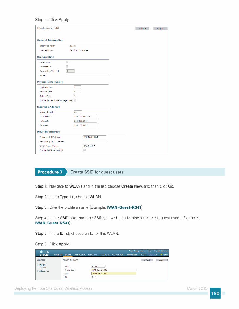
Deploying Remote Site Guest Wireless Access March 2015190
Step 9: Click Apply.
Procedure 3 Create SSID for guest users
Step 1: Navigate to WLANs and in the list, choose Create New, and then click Go.
Step 2: In the Type list, choose WLAN.
Step 3: Give the profile a name (Example: IWAN-Guest-RS41).
Step 4: In the SSID box, enter the SSID you wish to advertise for wireless guest users. (Example: IWAN-Guest-RS41).
Step 5: In the ID list, choose an ID for this WLAN.
Step 6: Click Apply.
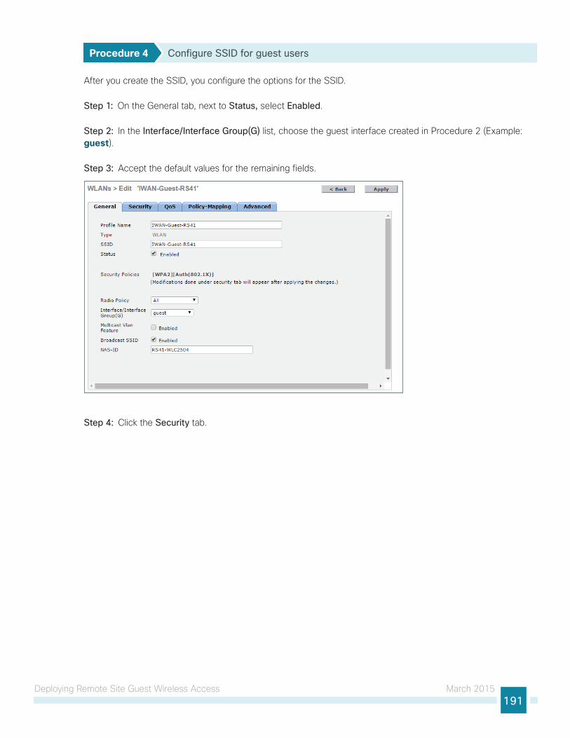
Deploying Remote Site Guest Wireless Access March 2015191
Procedure 4 Configure SSID for guest users
After you create the SSID, you configure the options for the SSID.
Step 1: On the General tab, next to Status, select Enabled.
Step 2: In the Interface/Interface Group(G) list, choose the guest interface created in Procedure 2 (Example: guest).
Step 3: Accept the default values for the remaining fields.
Step 4: Click the Security tab.
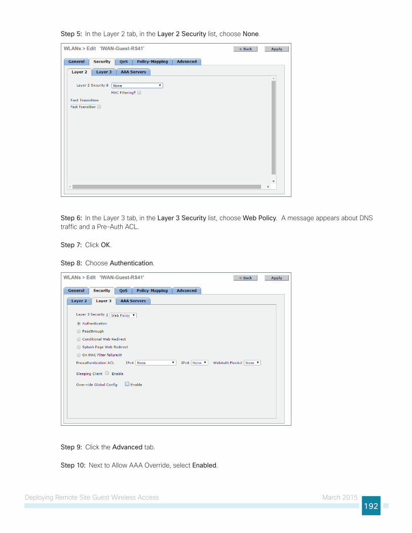
Deploying Remote Site Guest Wireless Access March 2015192
Step 5: In the Layer 2 tab, in the Layer 2 Security list, choose None.
Step 6: In the Layer 3 tab, in the Layer 3 Security list, choose Web Policy. A message appears about DNS traffic and a Pre-Auth ACL.
Step 7: Click OK.
Step 8: Choose Authentication.
Step 9: Click the Advanced tab.
Step 10: Next to Allow AAA Override, select Enabled.
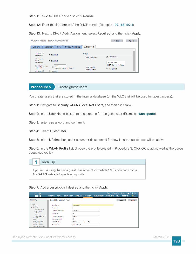
Deploying Remote Site Guest Wireless Access March 2015193
Step 11: Next to DHCP server, select Override.
Step 12: Enter the IP address of the DHCP server (Example: 192.168.192.1).
Step 13: Next to DHCP Addr. Assignment, select Required, and then click Apply.
Procedure 5 Create guest users
You create users that are stored in the internal database (on the WLC that will be used for guest access).
Step 1: Navigate to Security >AAA >Local Net Users, and then click New.
Step 2: In the User Name box, enter a username for the guest user (Example: iwan-guest).
Step 3: Enter a password and confirm it.
Step 4: Select Guest User.
Step 5: In the Lifetime box, enter a number (in seconds) for how long the guest user will be active.
Step 6: In the WLAN Profile list, choose the profile created in Procedure 3. Click OK to acknowledge the dialog about web-policy.
If you will be using the same guest user account for multiple SSIDs, you can choose Any WLAN instead of specifying a profile.
Tech Tip
Step 7: Add a description if desired and then click Apply.
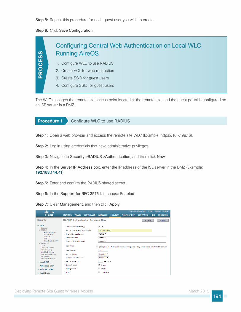
Deploying Remote Site Guest Wireless Access March 2015194
Step 8: Repeat this procedure for each guest user you wish to create.
Step 9: Click Save Configuration.
Configuring Central Web Authentication on Local WLC Running AireOS
1. Configure WLC to use RADIUS
2. Create ACL for web redirection
3. Create SSID for guest users
4. Configure SSID for guest users
PR
OC
ESS
The WLC manages the remote site access point located at the remote site, and the guest portal is configured on an ISE server in a DMZ.
Procedure 1 Configure WLC to use RADIUS
Step 1: Open a web browser and access the remote site WLC (Example: https://10.7.199.16).
Step 2: Log in using credentials that have administrative privileges.
Step 3: Navigate to Security >RADIUS >Authentication, and then click New.
Step 4: In the Server IP Address box, enter the IP address of the ISE server in the DMZ (Example: 192.168.144.41).
Step 5: Enter and confirm the RADIUS shared secret.
Step 6: In the Support for RFC 3576 list, choose Enabled.
Step 7: Clear Management, and then click Apply.
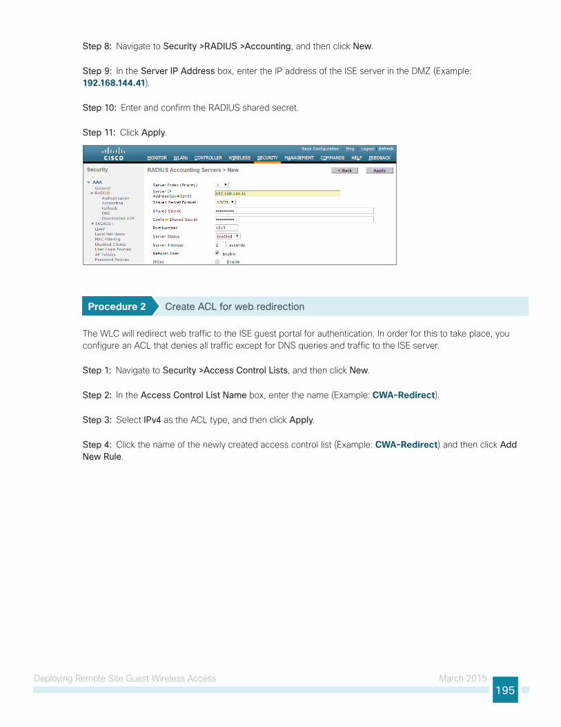
Deploying Remote Site Guest Wireless Access March 2015195
Step 8: Navigate to Security >RADIUS >Accounting, and then click New.
Step 9: In the Server IP Address box, enter the IP address of the ISE server in the DMZ (Example: 192.168.144.41).
Step 10: Enter and confirm the RADIUS shared secret.
Step 11: Click Apply.
Procedure 2 Create ACL for web redirection
The WLC will redirect web traffic to the ISE guest portal for authentication. In order for this to take place, you configure an ACL that denies all traffic except for DNS queries and traffic to the ISE server.
Step 1: Navigate to Security >Access Control Lists, and then click New.
Step 2: In the Access Control List Name box, enter the name (Example: CWA-Redirect).
Step 3: Select IPv4 as the ACL type, and then click Apply.
Step 4: Click the name of the newly created access control list (Example: CWA-Redirect) and then click Add New Rule.
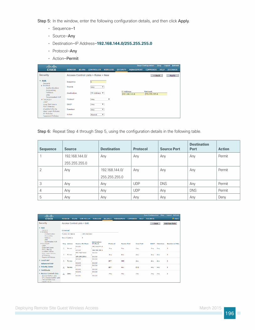
Deploying Remote Site Guest Wireless Access March 2015196
Step 5: In the window, enter the following configuration details, and then click Apply.
• Sequence—1
• Source—Any
• Destination—IP Address—192.168.144.0/255.255.255.0
• Protocol—Any
• Action—Permit
Step 6: Repeat Step 4 through Step 5, using the configuration details in the following table.
Sequence Source Destination Protocol Source PortDestination Port Action
1 192.168.144.0/
255.255.255.0
Any Any Any Any Permit
2 Any 192.168.144.0/
255.255.255.0
Any Any Any Permit
3 Any Any UDP DNS Any Permit
4 Any Any UDP Any DNS Permit
5 Any Any Any Any Any Deny
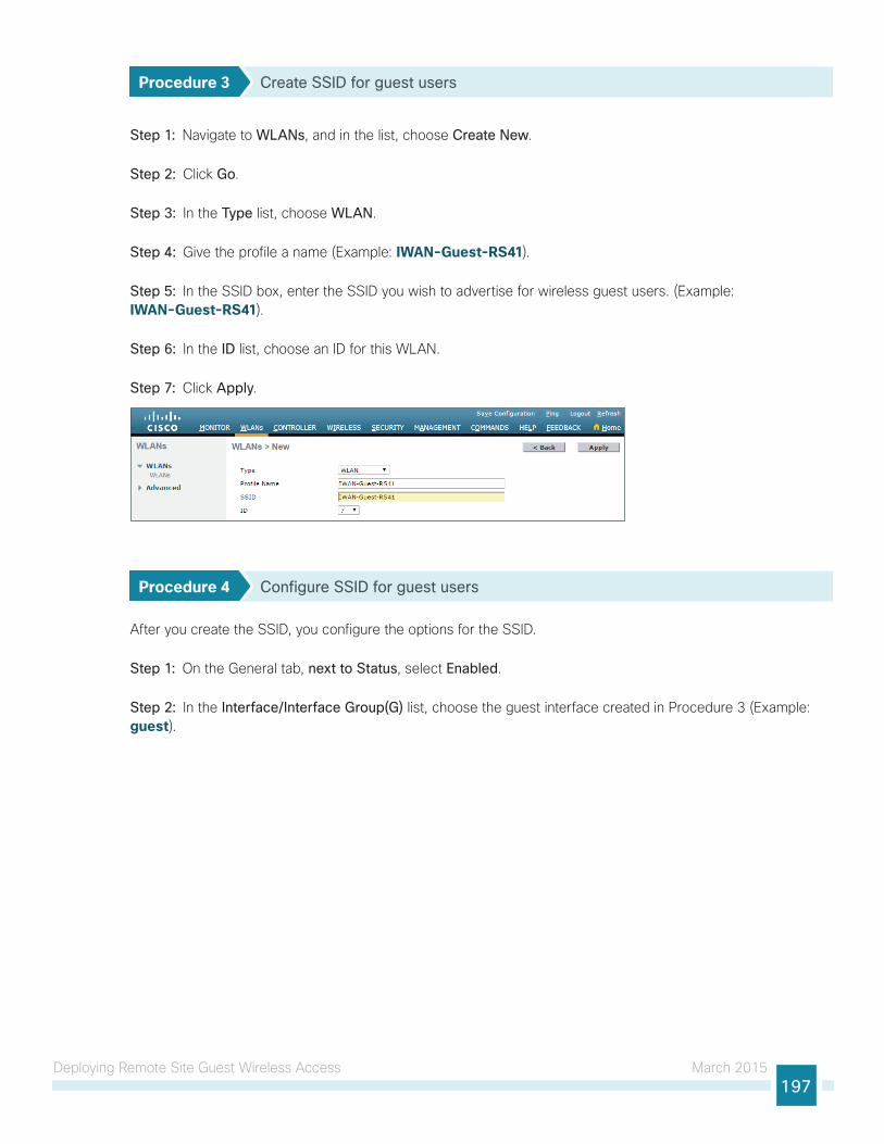
Deploying Remote Site Guest Wireless Access March 2015197
Procedure 3 Create SSID for guest users
Step 1: Navigate to WLANs, and in the list, choose Create New.
Step 2: Click Go.
Step 3: In the Type list, choose WLAN.
Step 4: Give the profile a name (Example: IWAN-Guest-RS41).
Step 5: In the SSID box, enter the SSID you wish to advertise for wireless guest users. (Example: IWAN-Guest-RS41).
Step 6: In the ID list, choose an ID for this WLAN.
Step 7: Click Apply.
Procedure 4 Configure SSID for guest users
After you create the SSID, you configure the options for the SSID.
Step 1: On the General tab, next to Status, select Enabled.
Step 2: In the Interface/Interface Group(G) list, choose the guest interface created in Procedure 3 (Example: guest).
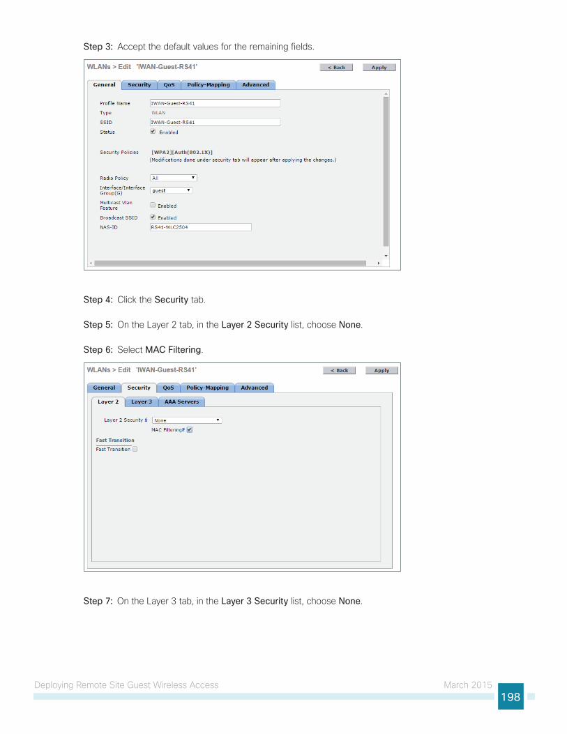
Deploying Remote Site Guest Wireless Access March 2015198
Step 3: Accept the default values for the remaining fields.
Step 4: Click the Security tab.
Step 5: On the Layer 2 tab, in the Layer 2 Security list, choose None.
Step 6: Select MAC Filtering.
Step 7: On the Layer 3 tab, in the Layer 3 Security list, choose None.
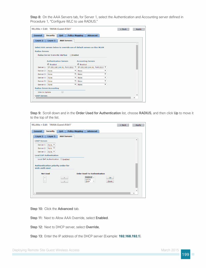
Deploying Remote Site Guest Wireless Access March 2015199
Step 8: On the AAA Servers tab, for Server 1, select the Authentication and Accounting server defined in Procedure 1, “Configure WLC to use RADIUS.”
Step 9: Scroll down and in the Order Used for Authentication list, choose RADIUS, and then click Up to move it to the top of the list.
Step 10: Click the Advanced tab.
Step 11: Next to Allow AAA Override, select Enabled.
Step 12: Next to DHCP server, select Override,
Step 13: Enter the IP address of the DHCP server (Example: 192.168.192.1).
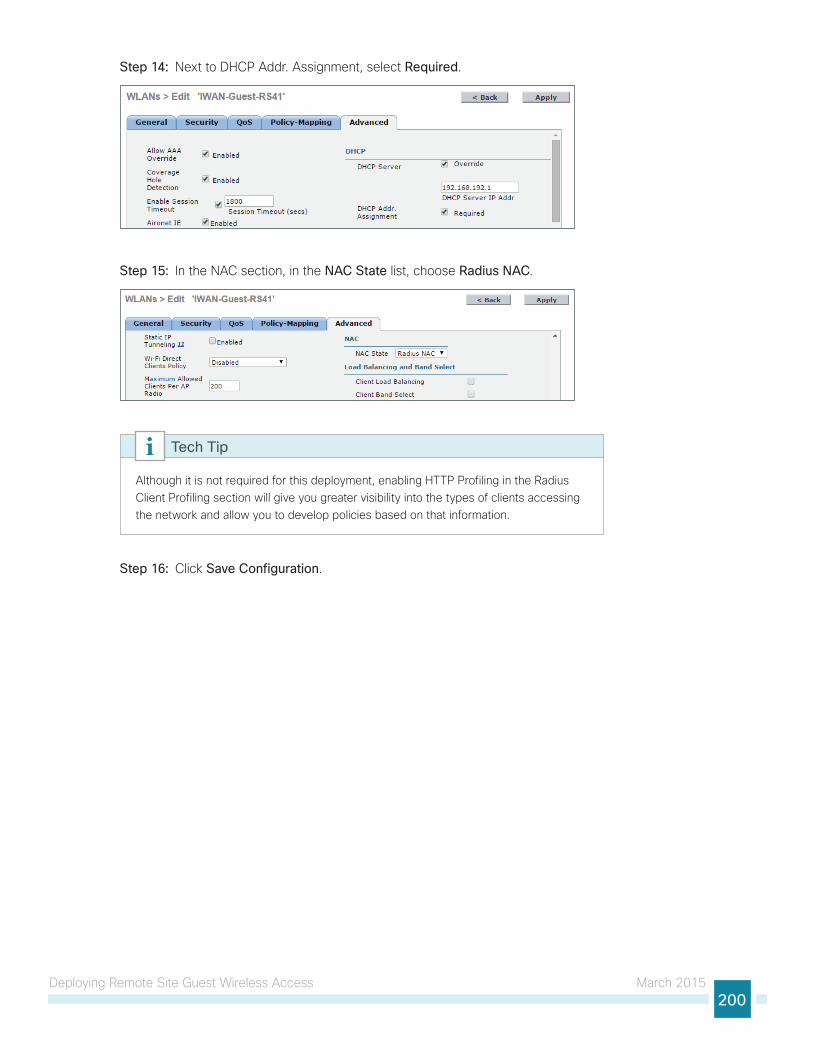
Deploying Remote Site Guest Wireless Access March 2015200
Step 14: Next to DHCP Addr. Assignment, select Required.
Step 15: In the NAC section, in the NAC State list, choose Radius NAC.
Although it is not required for this deployment, enabling HTTP Profiling in the Radius Client Profiling section will give you greater visibility into the types of clients accessing the network and allow you to develop policies based on that information.
Tech Tip
Step 16: Click Save Configuration.
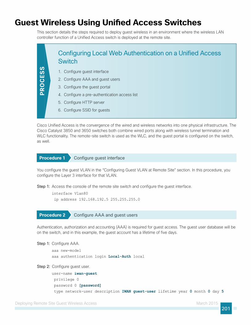
Deploying Remote Site Guest Wireless Access March 2015201
Guest Wireless Using Unified Access SwitchesThis section details the steps required to deploy guest wireless in an environment where the wireless LAN controller function of a Unified Access switch is deployed at the remote site.
Configuring Local Web Authentication on a Unified Access Switch
1. Configure guest interface
2. Configure AAA and guest users
3. Configure the guest portal
4. Configure a pre-authentication access list
5. Configure HTTP server
6. Configure SSID for guests
PR
OC
ESS
Cisco Unified Access is the convergence of the wired and wireless networks into one physical infrastructure. The Cisco Catalyst 3850 and 3650 switches both combine wired ports along with wireless tunnel termination and WLC functionality. The remote-site switch is used as the WLC, and the guest portal is configured on the switch, as well.
Procedure 1 Configure guest interface
You configure the guest VLAN in the “Configuring Guest VLAN at Remote Site” section. In this procedure, you configure the Layer 3 interface for that VLAN.
Step 1: Access the console of the remote site switch and configure the guest interface.
interface Vlan80
ip address 192.168.192.5 255.255.255.0
Procedure 2 Configure AAA and guest users
Authentication, authorization and accounting (AAA) is required for guest access. The guest user database will be on the switch, and in this example, the guest account has a lifetime of five days.
Step 1: Configure AAA.
aaa new-model
aaa authentication login Local-Auth local
Step 2: Configure guest user.
user-name iwan-guest privilege 0
password 0 [password] type network-user description IWAN guest-user lifetime year 0 month 0 day 5
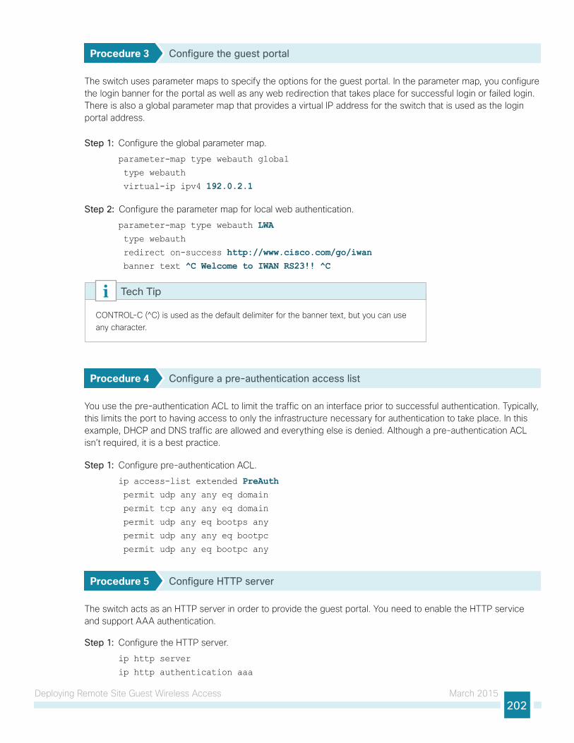
Deploying Remote Site Guest Wireless Access March 2015202
Procedure 3 Configure the guest portal
The switch uses parameter maps to specify the options for the guest portal. In the parameter map, you configure the login banner for the portal as well as any web redirection that takes place for successful login or failed login. There is also a global parameter map that provides a virtual IP address for the switch that is used as the login portal address.
Step 1: Configure the global parameter map.
parameter-map type webauth global
type webauth
virtual-ip ipv4 192.0.2.1
Step 2: Configure the parameter map for local web authentication.
parameter-map type webauth LWA type webauth
redirect on-success http://www.cisco.com/go/iwan banner text ^C Welcome to IWAN RS23!! ^C
CONTROL-C (̂ C) is used as the default delimiter for the banner text, but you can use any character.
Tech Tip
Procedure 4 Configure a pre-authentication access list
You use the pre-authentication ACL to limit the traffic on an interface prior to successful authentication. Typically, this limits the port to having access to only the infrastructure necessary for authentication to take place. In this example, DHCP and DNS traffic are allowed and everything else is denied. Although a pre-authentication ACL isn’t required, it is a best practice.
Step 1: Configure pre-authentication ACL.
ip access-list extended PreAuth permit udp any any eq domain
permit tcp any any eq domain
permit udp any eq bootps any
permit udp any any eq bootpc
permit udp any eq bootpc any
Procedure 5 Configure HTTP server
The switch acts as an HTTP server in order to provide the guest portal. You need to enable the HTTP service and support AAA authentication.
Step 1: Configure the HTTP server.
ip http server
ip http authentication aaa
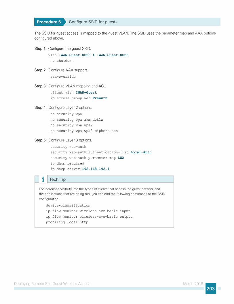
Deploying Remote Site Guest Wireless Access March 2015203
Procedure 6 Configure SSID for guests
The SSID for guest access is mapped to the guest VLAN. The SSID uses the parameter map and AAA options configured above.
Step 1: Configure the guest SSID.
wlan IWAN-Guest-RS23 4 IWAN-Guest-RS23 no shutdown
Step 2: Configure AAA support.
aaa-override
Step 3: Configure VLAN mapping and ACL.
client vlan IWAN-Guest ip access-group web PreAuth
Step 4: Configure Layer 2 options.
no security wpa
no security wpa akm dot1x
no security wpa wpa2
no security wpa wpa2 ciphers aes
Step 5: Configure Layer 3 options.
security web-auth
security web-auth authentication-list Local-Auth security web-auth parameter-map LWA ip dhcp required
ip dhcp server 192.168.192.1
For increased visibility into the types of clients that access the guest network and the applications that are being run, you can add the following commands to the SSID configuration.
device-classification
ip flow monitor wireless-avc-basic input
ip flow monitor wireless-avc-basic output
profiling local http
Tech Tip
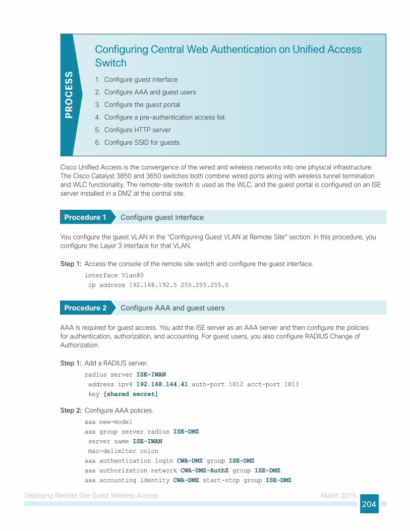
Deploying Remote Site Guest Wireless Access March 2015204
Configuring Central Web Authentication on Unified Access Switch
1. Configure guest interface
2. Configure AAA and guest users
3. Configure the guest portal
4. Configure a pre-authentication access list
5. Configure HTTP server
6. Configure SSID for guests
PR
OC
ESS
Cisco Unified Access is the convergence of the wired and wireless networks into one physical infrastructure. The Cisco Catalyst 3850 and 3650 switches both combine wired ports along with wireless tunnel termination and WLC functionality. The remote-site switch is used as the WLC, and the guest portal is configured on an ISE server installed in a DMZ at the central site.
Procedure 1 Configure guest interface
You configure the guest VLAN in the “Configuring Guest VLAN at Remote Site” section. In this procedure, you configure the Layer 3 interface for that VLAN.
Step 1: Access the console of the remote site switch and configure the guest interface.
interface Vlan80
ip address 192.168.192.5 255.255.255.0
Procedure 2 Configure AAA and guest users
AAA is required for guest access. You add the ISE server as an AAA server and then configure the policies for authentication, authorization, and accounting. For guest users, you also configure RADIUS Change of Authorization.
Step 1: Add a RADIUS server.
radius server ISE-IWAN address ipv4 192.168.144.41 auth-port 1812 acct-port 1813 key [shared secret]
Step 2: Configure AAA policies.
aaa new-model
aaa group server radius ISE-DMZ server name ISE-IWAN mac-delimiter colon
aaa authentication login CWA-DMZ group ISE-DMZaaa authorization network CWA-DMZ-AuthZ group ISE-DMZaaa accounting identity CWA-DMZ start-stop group ISE-DMZ
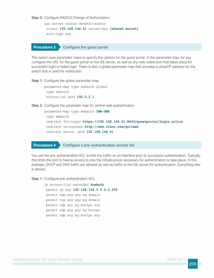
Deploying Remote Site Guest Wireless Access March 2015205
Step 3: Configure RADIUS Change of Authorization.
aaa server radius dynamic-author
client 192.168.144.41 server-key [shared secret] auth-type any
Procedure 3 Configure the guest portal
The switch uses parameter maps to specify the options for the guest portal. In the parameter map, for you configure the URL for the guest portal on the ISE server, as well as any web redirection that takes place for successful login or failed login. There is also a global parameter map that provides a virtual IP address for the switch that is used for redirection.
Step 1: Configure the global parameter map.
parameter-map type webauth global
type webauth
virtual-ip ipv4 192.0.2.1
Step 2: Configure the parameter map for central web authentication.
parameter-map type webauth CWA-DMZ type webauth
redirect for-login https://192.168.144.41:8443/guestportal/Login.action redirect on-success http://www.cisco.com/go/iwan redirect portal ipv4 192.168.144.41
Procedure 4 Configure a pre-authentication access list
You use the pre-authentication ACL to limit the traffic on an interface prior to successful authentication. Typically, this limits the port to having access to only the infrastructure necessary for authentication to take place. In this example, DHCP and DNS traffic are allowed as well as traffic to the ISE server for authentication. Everything else is denied.
Step 1: Configure pre-authentication ACL.
ip access-list extended PreAuth permit ip any 192.168.144.0 0.0.0.255 permit udp any any eq domain
permit tcp any any eq domain
permit udp any eq bootps any
permit udp any any eq bootpc
permit udp any eq bootpc any
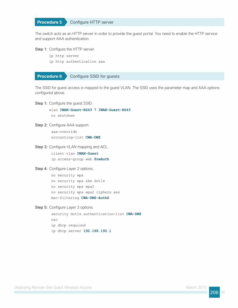
Deploying Remote Site Guest Wireless Access March 2015206
Procedure 5 Configure HTTP server
The switch acts as an HTTP server in order to provide the guest portal. You need to enable the HTTP service and support AAA authentication.
Step 1: Configure the HTTP server.
ip http server
ip http authentication aaa
Procedure 6 Configure SSID for guests
The SSID for guest access is mapped to the guest VLAN. The SSID uses the parameter map and AAA options configured above.
Step 1: Configure the guest SSID.
wlan IWAN-Guest-RS43 7 IWAN-Guest-RS43 no shutdown
Step 2: Configure AAA support.
aaa-override
accounting-list CWA-DMZ
Step 3: Configure VLAN mapping and ACL.
client vlan IWAN-Guest ip access-group web PreAuth
Step 4: Configure Layer 2 options.
no security wpa
no security wpa akm dot1x
no security wpa wpa2
no security wpa wpa2 ciphers aes
mac-filtering CWA-DMZ-AuthZ
Step 5: Configure Layer 3 options.
security dot1x authentication-list CWA-DMZ nac ip dhcp required
ip dhcp server 192.168.192.1
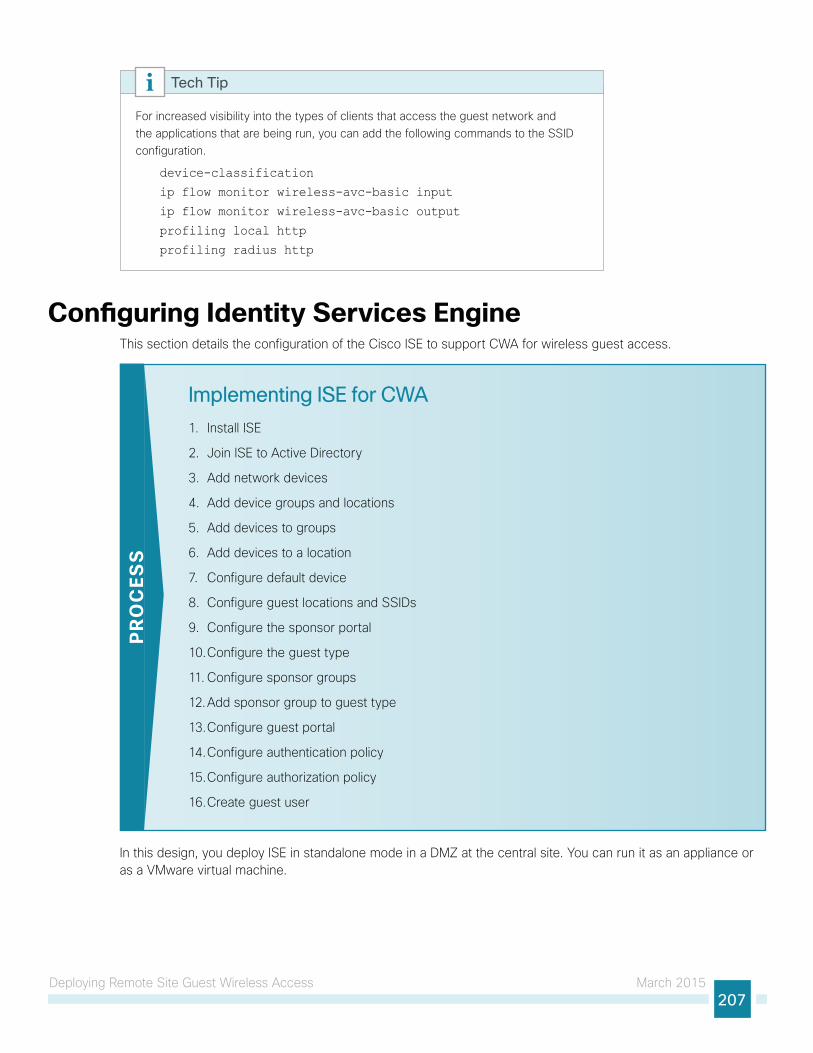
Deploying Remote Site Guest Wireless Access March 2015207
For increased visibility into the types of clients that access the guest network and the applications that are being run, you can add the following commands to the SSID configuration.
device-classification
ip flow monitor wireless-avc-basic input
ip flow monitor wireless-avc-basic output
profiling local http
profiling radius http
Tech Tip
Configuring Identity Services EngineThis section details the configuration of the Cisco ISE to support CWA for wireless guest access.
Implementing ISE for CWA
1. Install ISE
2. Join ISE to Active Directory
3. Add network devices
4. Add device groups and locations
5. Add devices to groups
6. Add devices to a location
7. Configure default device
8. Configure guest locations and SSIDs
9. Configure the sponsor portal
10. Configure the guest type
11. Configure sponsor groups
12. Add sponsor group to guest type
13. Configure guest portal
14. Configure authentication policy
15. Configure authorization policy
16. Create guest user
PR
OC
ESS
In this design, you deploy ISE in standalone mode in a DMZ at the central site. You can run it as an appliance or as a VMware virtual machine.
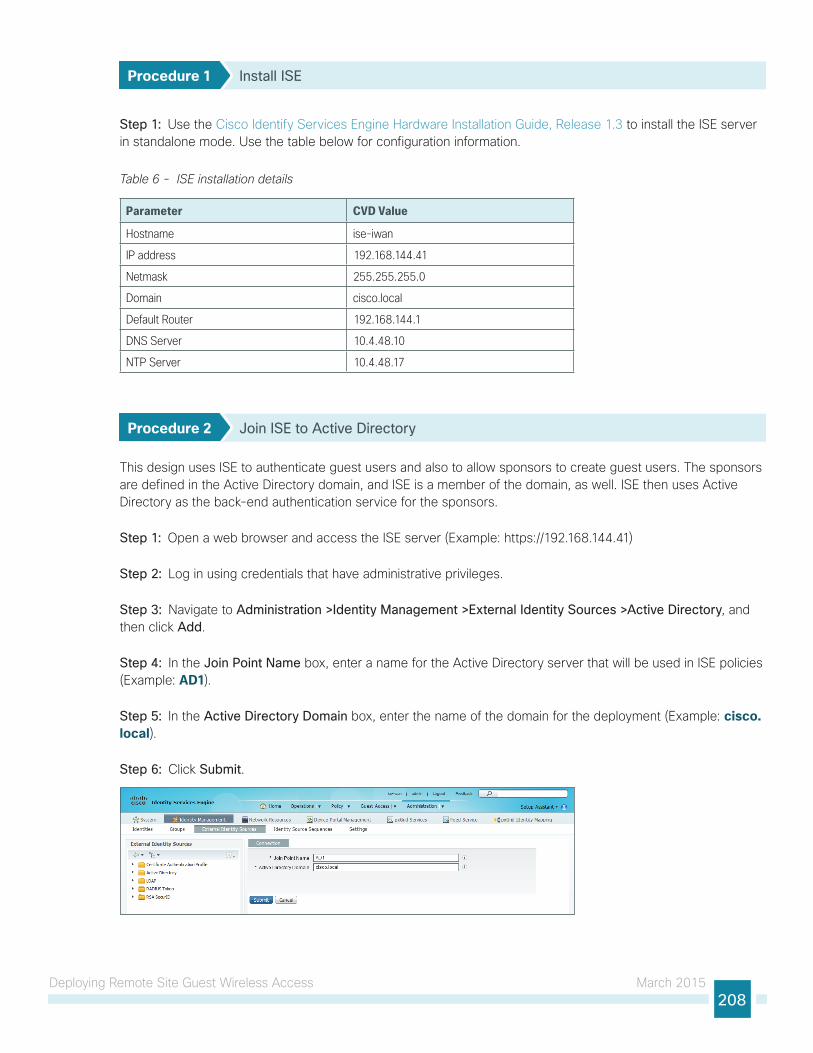
Deploying Remote Site Guest Wireless Access March 2015208
Procedure 1 Install ISE
Step 1: Use the Cisco Identify Services Engine Hardware Installation Guide, Release 1.3 to install the ISE server in standalone mode. Use the table below for configuration information.
Table 6 - ISE installation details
Parameter CVD Value
Hostname ise-iwan
IP address 192.168.144.41
Netmask 255.255.255.0
Domain cisco.local
Default Router 192.168.144.1
DNS Server 10.4.48.10
NTP Server 10.4.48.17
Procedure 2 Join ISE to Active Directory
This design uses ISE to authenticate guest users and also to allow sponsors to create guest users. The sponsors are defined in the Active Directory domain, and ISE is a member of the domain, as well. ISE then uses Active Directory as the back-end authentication service for the sponsors.
Step 1: Open a web browser and access the ISE server (Example: https://192.168.144.41)
Step 2: Log in using credentials that have administrative privileges.
Step 3: Navigate to Administration >Identity Management >External Identity Sources >Active Directory, and then click Add.
Step 4: In the Join Point Name box, enter a name for the Active Directory server that will be used in ISE policies (Example: AD1).
Step 5: In the Active Directory Domain box, enter the name of the domain for the deployment (Example: cisco.local).
Step 6: Click Submit.
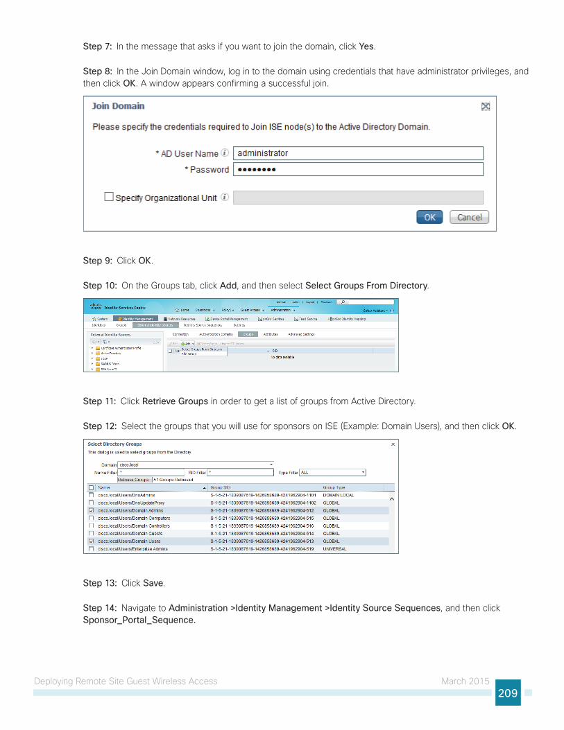
Deploying Remote Site Guest Wireless Access March 2015209
Step 7: In the message that asks if you want to join the domain, click Yes.
Step 8: In the Join Domain window, log in to the domain using credentials that have administrator privileges, and then click OK. A window appears confirming a successful join.
Step 9: Click OK.
Step 10: On the Groups tab, click Add, and then select Select Groups From Directory.
Step 11: Click Retrieve Groups in order to get a list of groups from Active Directory.
Step 12: Select the groups that you will use for sponsors on ISE (Example: Domain Users), and then click OK.
Step 13: Click Save.
Step 14: Navigate to Administration >Identity Management >Identity Source Sequences, and then click Sponsor_Portal_Sequence.
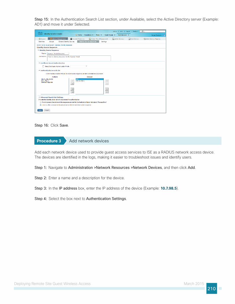
Deploying Remote Site Guest Wireless Access March 2015210
Step 15: In the Authentication Search List section, under Available, select the Active Directory server (Example: AD1) and move it under Selected.
Step 16: Click Save.
Procedure 3 Add network devices
Add each network device used to provide guest access services to ISE as a RADIUS network access device. The devices are identified in the logs, making it easier to troubleshoot issues and identify users.
Step 1: Navigate to Administration >Network Resources >Network Devices, and then click Add.
Step 2: Enter a name and a description for the device.
Step 3: In the IP address box, enter the IP address of the device (Example: 10.7.98.5).
Step 4: Select the box next to Authentication Settings.
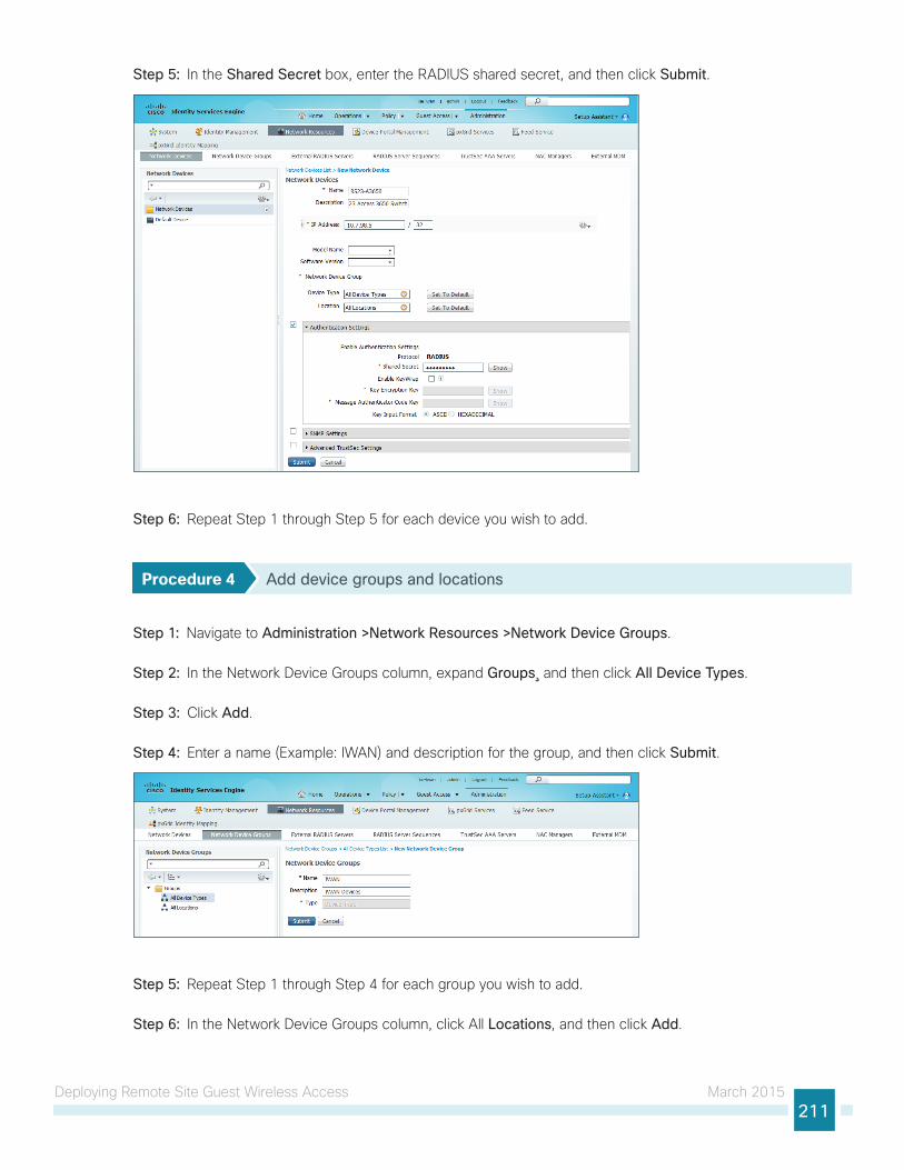
Deploying Remote Site Guest Wireless Access March 2015211
Step 5: In the Shared Secret box, enter the RADIUS shared secret, and then click Submit.
Step 6: Repeat Step 1 through Step 5 for each device you wish to add.
Procedure 4 Add device groups and locations
Step 1: Navigate to Administration >Network Resources >Network Device Groups.
Step 2: In the Network Device Groups column, expand Groups¸ and then click All Device Types.
Step 3: Click Add.
Step 4: Enter a name (Example: IWAN) and description for the group, and then click Submit.
Step 5: Repeat Step 1 through Step 4 for each group you wish to add.
Step 6: In the Network Device Groups column, click All Locations, and then click Add.
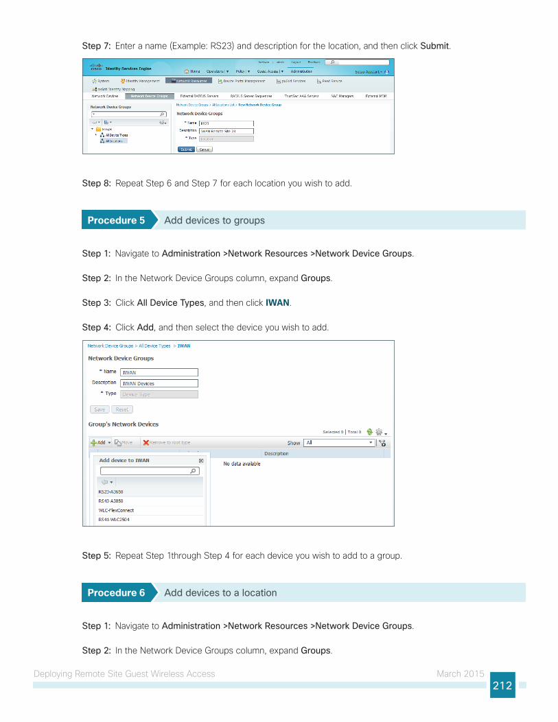
Deploying Remote Site Guest Wireless Access March 2015212
Step 7: Enter a name (Example: RS23) and description for the location, and then click Submit.
Step 8: Repeat Step 6 and Step 7 for each location you wish to add.
Procedure 5 Add devices to groups
Step 1: Navigate to Administration >Network Resources >Network Device Groups.
Step 2: In the Network Device Groups column, expand Groups.
Step 3: Click All Device Types, and then click IWAN.
Step 4: Click Add, and then select the device you wish to add.
Step 5: Repeat Step 1through Step 4 for each device you wish to add to a group.
Procedure 6 Add devices to a location
Step 1: Navigate to Administration >Network Resources >Network Device Groups.
Step 2: In the Network Device Groups column, expand Groups.
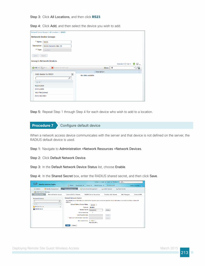
Deploying Remote Site Guest Wireless Access March 2015213
Step 3: Click All Locations, and then click RS23.
Step 4: Click Add, and then select the device you wish to add.
Step 5: Repeat Step 1 through Step 4 for each device who wish to add to a location.
Procedure 7 Configure default device
When a network access device communicates with the server and that device is not defined on the server, the RADIUS default device is used.
Step 1: Navigate to Administration >Network Resources >Network Devices.
Step 2: Click Default Network Device.
Step 3: In the Default Network Device Status list, choose Enable.
Step 4: In the Shared Secret box, enter the RADIUS shared secret, and then click Save.
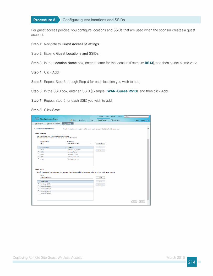
Deploying Remote Site Guest Wireless Access March 2015214
Procedure 8 Configure guest locations and SSIDs
For guest access policies, you configure locations and SSIDs that are used when the sponsor creates a guest account.
Step 1: Navigate to Guest Access >Settings.
Step 2: Expand Guest Locations and SSIDs.
Step 3: In the Location Name box, enter a name for the location (Example: RS13), and then select a time zone.
Step 4: Click Add.
Step 5: Repeat Step 3 through Step 4 for each location you wish to add.
Step 6: In the SSID box, enter an SSID (Example: IWAN-Guest-RS13), and then click Add.
Step 7: Repeat Step 6 for each SSID you wish to add.
Step 8: Click Save.
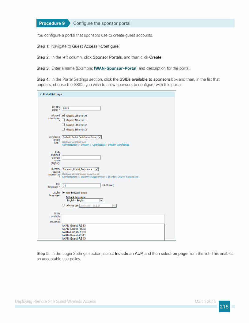
Deploying Remote Site Guest Wireless Access March 2015215
Procedure 9 Configure the sponsor portal
You configure a portal that sponsors use to create guest accounts.
Step 1: Navigate to Guest Access >Configure.
Step 2: In the left column, click Sponsor Portals, and then click Create.
Step 3: Enter a name (Example: IWAN-Sponsor-Portal) and description for the portal.
Step 4: In the Portal Settings section, click the SSIDs available to sponsors box and then, in the list that appears, choose the SSIDs you wish to allow sponsors to configure with this portal.
Step 5: In the Login Settings section, select Include an AUP, and then select on page from the list. This enables an acceptable use policy.
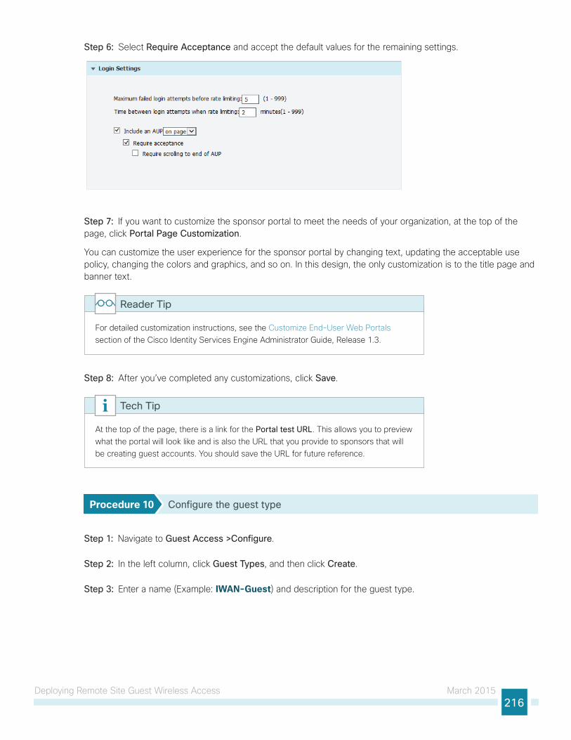
Deploying Remote Site Guest Wireless Access March 2015216
Step 6: Select Require Acceptance and accept the default values for the remaining settings.
Step 7: If you want to customize the sponsor portal to meet the needs of your organization, at the top of the page, click Portal Page Customization.
You can customize the user experience for the sponsor portal by changing text, updating the acceptable use policy, changing the colors and graphics, and so on. In this design, the only customization is to the title page and banner text.
For detailed customization instructions, see the Customize End-User Web Portals section of the Cisco Identity Services Engine Administrator Guide, Release 1.3.
Reader Tip
Step 8: After you’ve completed any customizations, click Save.
At the top of the page, there is a link for the Portal test URL. This allows you to preview what the portal will look like and is also the URL that you provide to sponsors that will be creating guest accounts. You should save the URL for future reference.
Tech Tip
Procedure 10 Configure the guest type
Step 1: Navigate to Guest Access >Configure.
Step 2: In the left column, click Guest Types, and then click Create.
Step 3: Enter a name (Example: IWAN-Guest) and description for the guest type.
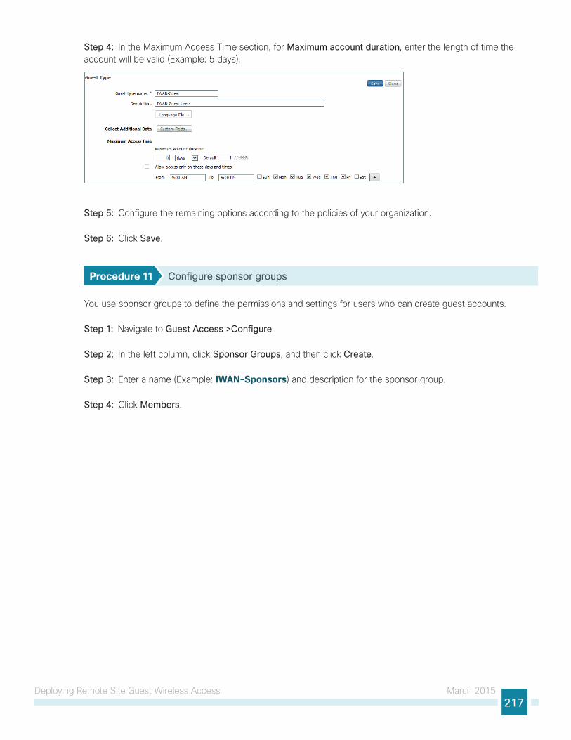
Deploying Remote Site Guest Wireless Access March 2015217
Step 4: In the Maximum Access Time section, for Maximum account duration, enter the length of time the account will be valid (Example: 5 days).
Step 5: Configure the remaining options according to the policies of your organization.
Step 6: Click Save.
Procedure 11 Configure sponsor groups
You use sponsor groups to define the permissions and settings for users who can create guest accounts.
Step 1: Navigate to Guest Access >Configure.
Step 2: In the left column, click Sponsor Groups, and then click Create.
Step 3: Enter a name (Example: IWAN-Sponsors) and description for the sponsor group.
Step 4: Click Members.
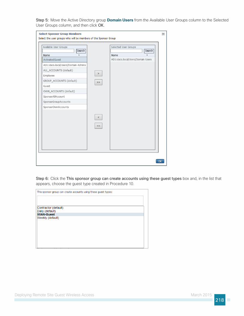
Deploying Remote Site Guest Wireless Access March 2015218
Step 5: Move the Active Directory group Domain Users from the Available User Groups column to the Selected User Groups column, and then click OK.
Step 6: Click the This sponsor group can create accounts using these guest types box and, in the list that appears, choose the guest type created in Procedure 10.
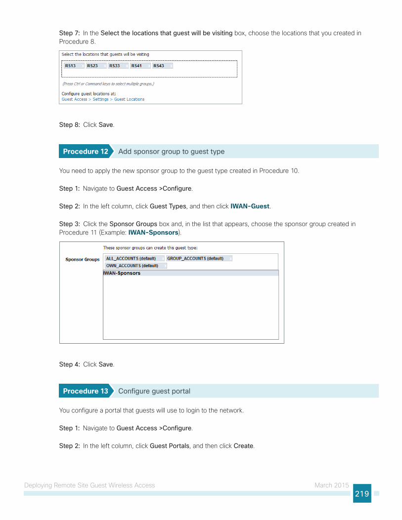
Deploying Remote Site Guest Wireless Access March 2015219
Step 7: In the Select the locations that guest will be visiting box, choose the locations that you created in Procedure 8.
Step 8: Click Save.
Procedure 12 Add sponsor group to guest type
You need to apply the new sponsor group to the guest type created in Procedure 10.
Step 1: Navigate to Guest Access >Configure.
Step 2: In the left column, click Guest Types, and then click IWAN-Guest.
Step 3: Click the Sponsor Groups box and, in the list that appears, choose the sponsor group created in Procedure 11 (Example: IWAN-Sponsors).
Step 4: Click Save.
Procedure 13 Configure guest portal
You configure a portal that guests will use to login to the network.
Step 1: Navigate to Guest Access >Configure.
Step 2: In the left column, click Guest Portals, and then click Create.
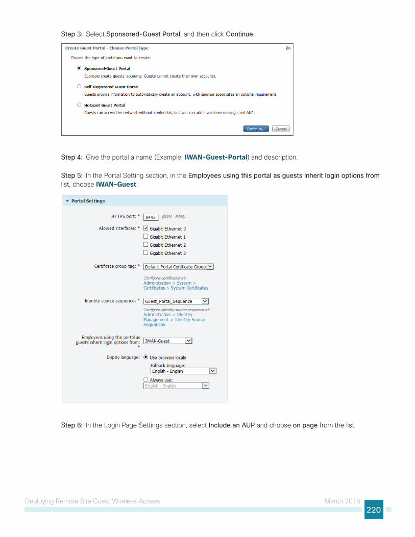
Deploying Remote Site Guest Wireless Access March 2015220
Step 3: Select Sponsored-Guest Portal, and then click Continue.
Step 4: Give the portal a name (Example: IWAN-Guest-Portal) and description.
Step 5: In the Portal Setting section, in the Employees using this portal as guests inherit login options from list, choose IWAN-Guest.
Step 6: In the Login Page Settings section, select Include an AUP and choose on page from the list.
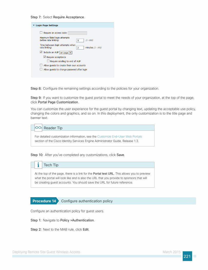
Deploying Remote Site Guest Wireless Access March 2015221
Step 7: Select Require Acceptance.
Step 8: Configure the remaining settings according to the policies for your organization.
Step 9: If you want to customize the guest portal to meet the needs of your organization, at the top of the page, click Portal Page Customization.
You can customize the user experience for the guest portal by changing text, updating the acceptable use policy, changing the colors and graphics, and so on. In this deployment, the only customization is to the title page and banner text.
For detailed customization information, see the Customize End-User Web Portals section of the Cisco Identity Services Engine Administrator Guide, Release 1.3.
Reader Tip
Step 10: After you’ve completed any customizations, click Save.
At the top of the page, there is a link for the Portal test URL. This allows you to preview what the portal will look like and is also the URL that you provide to sponsors that will be creating guest accounts. You should save the URL for future reference.
Tech Tip
Procedure 14 Configure authentication policy
Configure an authentication policy for guest users.
Step 1: Navigate to Policy >Authentication.
Step 2: Next to the MAB rule, click Edit.
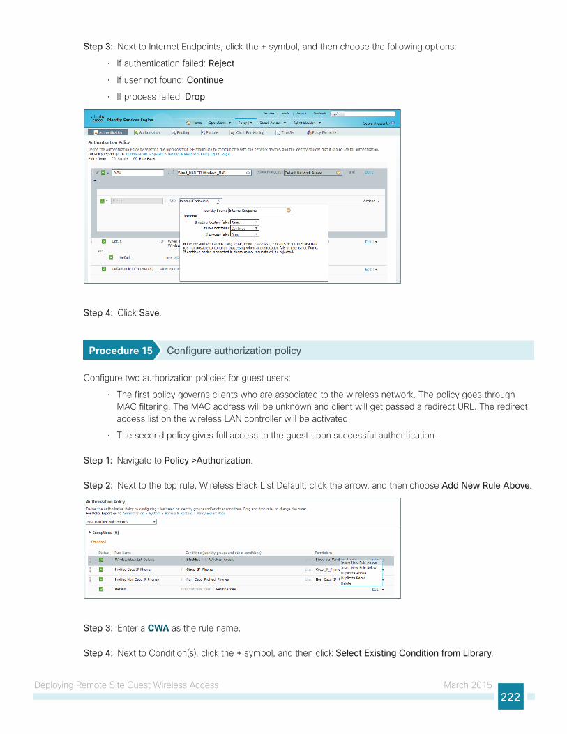
Deploying Remote Site Guest Wireless Access March 2015222
Step 3: Next to Internet Endpoints, click the + symbol, and then choose the following options:
• If authentication failed: Reject
• If user not found: Continue
• If process failed: Drop
Step 4: Click Save.
Procedure 15 Configure authorization policy
Configure two authorization policies for guest users:
• The first policy governs clients who are associated to the wireless network. The policy goes through MAC filtering. The MAC address will be unknown and client will get passed a redirect URL. The redirect access list on the wireless LAN controller will be activated.
• The second policy gives full access to the guest upon successful authentication.
Step 1: Navigate to Policy >Authorization.
Step 2: Next to the top rule, Wireless Black List Default, click the arrow, and then choose Add New Rule Above.
Step 3: Enter a CWA as the rule name.
Step 4: Next to Condition(s), click the + symbol, and then click Select Existing Condition from Library.
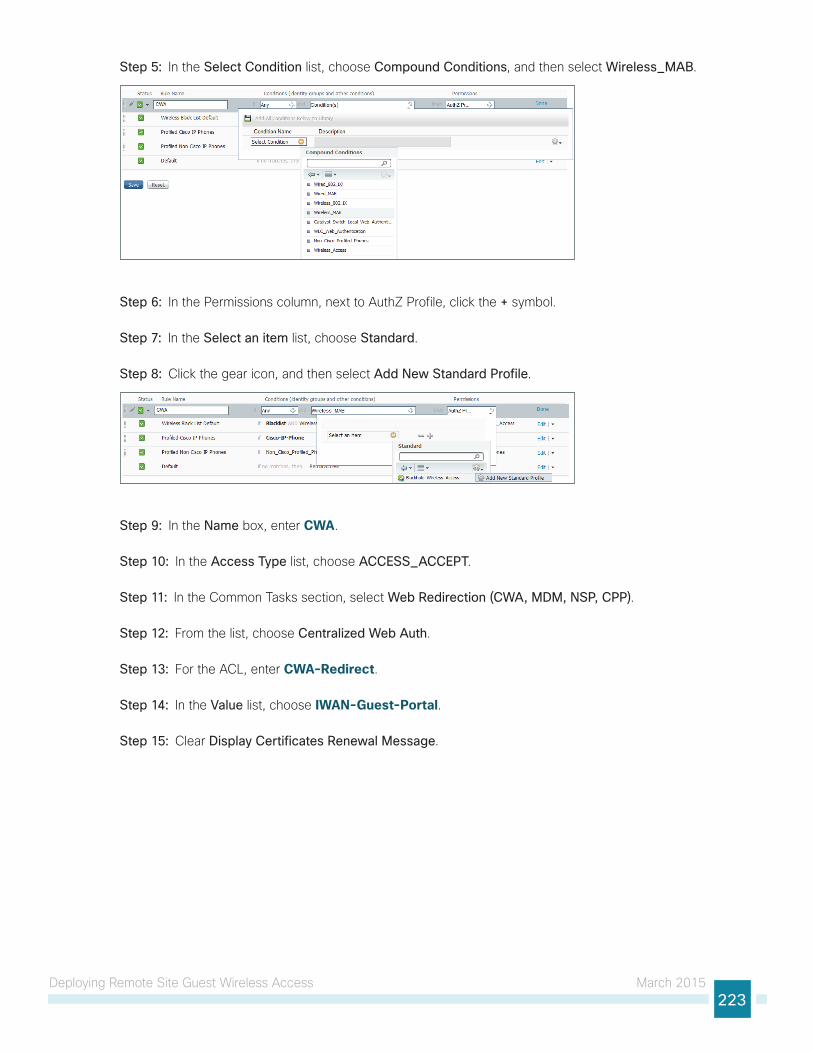
Deploying Remote Site Guest Wireless Access March 2015223
Step 5: In the Select Condition list, choose Compound Conditions, and then select Wireless_MAB.
Step 6: In the Permissions column, next to AuthZ Profile, click the + symbol.
Step 7: In the Select an item list, choose Standard.
Step 8: Click the gear icon, and then select Add New Standard Profile.
Step 9: In the Name box, enter CWA.
Step 10: In the Access Type list, choose ACCESS_ACCEPT.
Step 11: In the Common Tasks section, select Web Redirection (CWA, MDM, NSP, CPP).
Step 12: From the list, choose Centralized Web Auth.
Step 13: For the ACL, enter CWA-Redirect.
Step 14: In the Value list, choose IWAN-Guest-Portal.
Step 15: Clear Display Certificates Renewal Message.
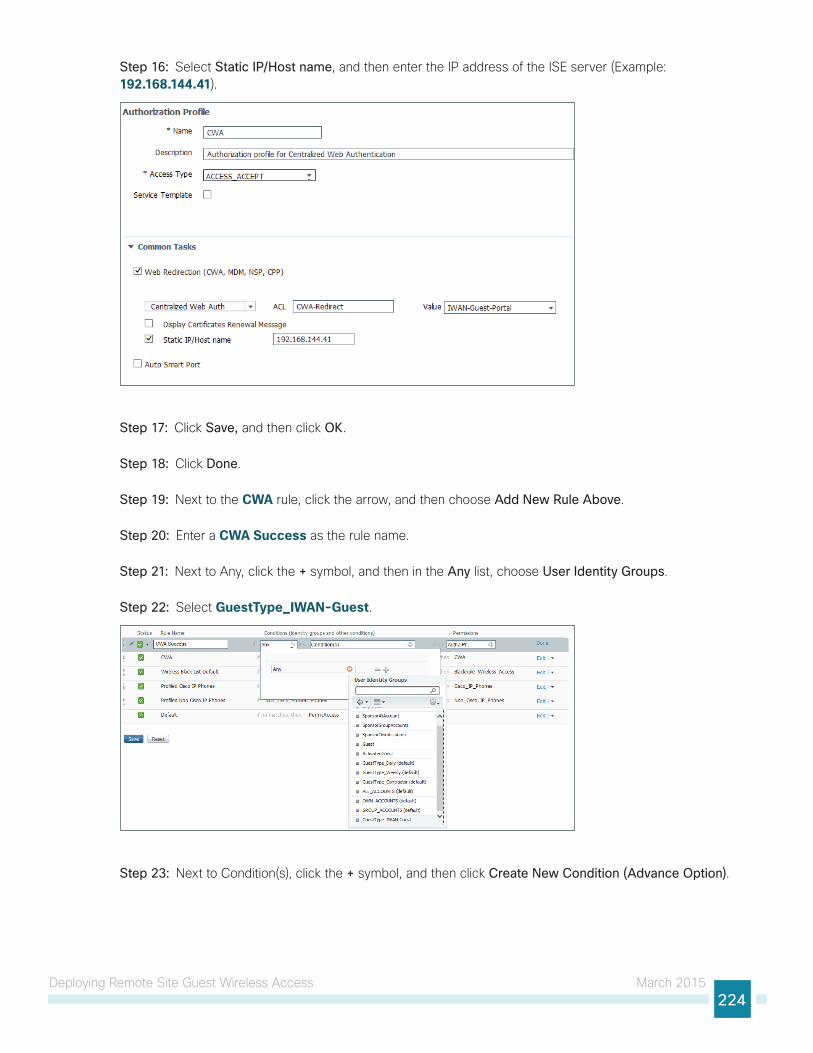
Deploying Remote Site Guest Wireless Access March 2015224
Step 16: Select Static IP/Host name, and then enter the IP address of the ISE server (Example: 192.168.144.41).
Step 17: Click Save, and then click OK.
Step 18: Click Done.
Step 19: Next to the CWA rule, click the arrow, and then choose Add New Rule Above.
Step 20: Enter a CWA Success as the rule name.
Step 21: Next to Any, click the + symbol, and then in the Any list, choose User Identity Groups.
Step 22: Select GuestType_IWAN-Guest.
Step 23: Next to Condition(s), click the + symbol, and then click Create New Condition (Advance Option).
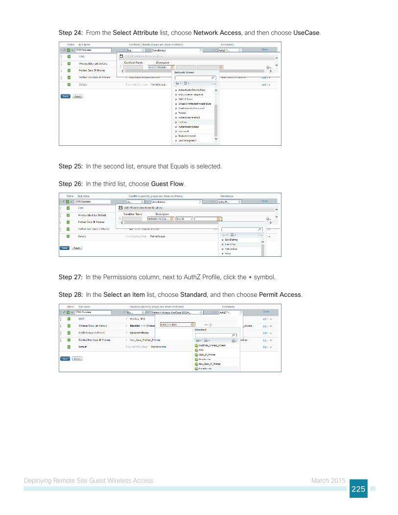
Deploying Remote Site Guest Wireless Access March 2015225
Step 24: From the Select Attribute list, choose Network Access, and then choose UseCase.
Step 25: In the second list, ensure that Equals is selected.
Step 26: In the third list, choose Guest Flow.
Step 27: In the Permissions column, next to AuthZ Profile, click the + symbol.
Step 28: In the Select an item list, choose Standard, and then choose Permit Access.
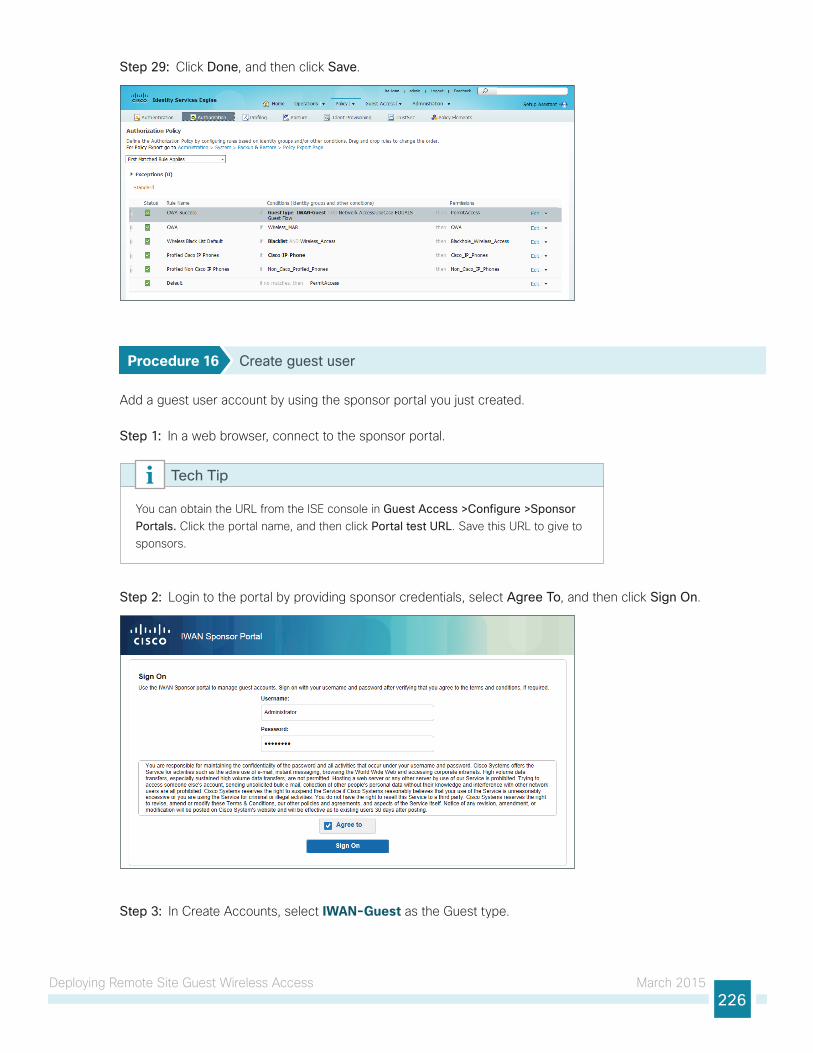
Deploying Remote Site Guest Wireless Access March 2015226
Step 29: Click Done, and then click Save.
Procedure 16 Create guest user
Add a guest user account by using the sponsor portal you just created.
Step 1: In a web browser, connect to the sponsor portal.
You can obtain the URL from the ISE console in Guest Access >Configure >Sponsor Portals. Click the portal name, and then click Portal test URL. Save this URL to give to sponsors.
Tech Tip
Step 2: Login to the portal by providing sponsor credentials, select Agree To, and then click Sign On.
Step 3: In Create Accounts, select IWAN-Guest as the Guest type.
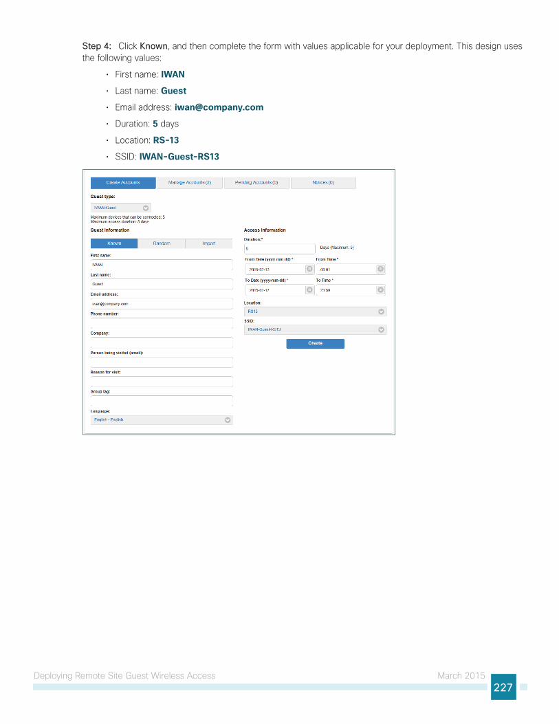
Deploying Remote Site Guest Wireless Access March 2015227
Step 4: Click Known, and then complete the form with values applicable for your deployment. This design uses the following values:
• First name: IWAN
• Last name: Guest
• Email address: [email protected]
• Duration: 5 days
• Location: RS-13
• SSID: IWAN-Guest-RS13
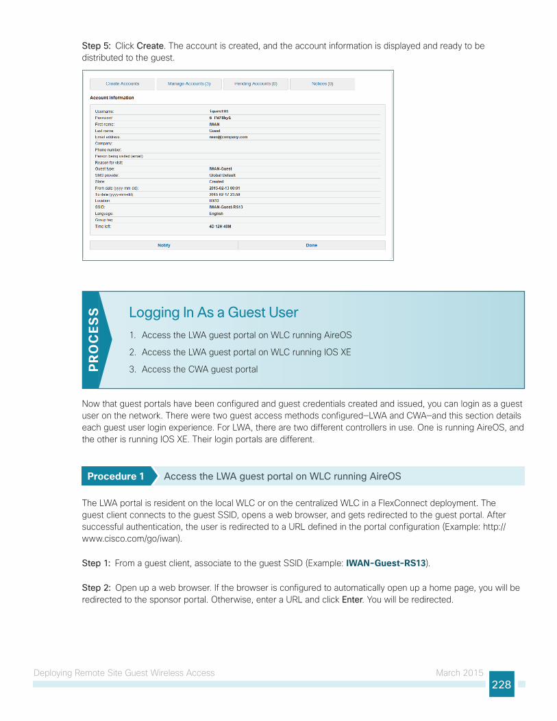
Deploying Remote Site Guest Wireless Access March 2015228
Step 5: Click Create. The account is created, and the account information is displayed and ready to be distributed to the guest.
Logging In As a Guest User
1. Access the LWA guest portal on WLC running AireOS
2. Access the LWA guest portal on WLC running IOS XE
3. Access the CWA guest portalPR
OC
ESS
Now that guest portals have been configured and guest credentials created and issued, you can login as a guest user on the network. There were two guest access methods configured—LWA and CWA—and this section details each guest user login experience. For LWA, there are two different controllers in use. One is running AireOS, and the other is running IOS XE. Their login portals are different.
Procedure 1 Access the LWA guest portal on WLC running AireOS
The LWA portal is resident on the local WLC or on the centralized WLC in a FlexConnect deployment. The guest client connects to the guest SSID, opens a web browser, and gets redirected to the guest portal. After successful authentication, the user is redirected to a URL defined in the portal configuration (Example: http://www.cisco.com/go/iwan).
Step 1: From a guest client, associate to the guest SSID (Example: IWAN-Guest-RS13).
Step 2: Open up a web browser. If the browser is configured to automatically open up a home page, you will be redirected to the sponsor portal. Otherwise, enter a URL and click Enter. You will be redirected.
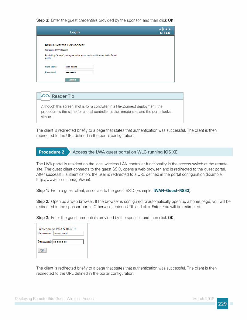
Deploying Remote Site Guest Wireless Access March 2015229
Step 3: Enter the guest credentials provided by the sponsor, and then click OK.
Although this screen shot is for a controller in a FlexConnect deployment, the procedure is the same for a local controller at the remote site, and the portal looks similar.
Reader Tip
The client is redirected briefly to a page that states that authentication was successful. The client is then redirected to the URL defined in the portal configuration.
Procedure 2 Access the LWA guest portal on WLC running IOS XE
The LWA portal is resident on the local wireless LAN controller functionality in the access switch at the remote site. The guest client connects to the guest SSID, opens a web browser, and is redirected to the guest portal. After successful authentication, the user is redirected to a URL defined in the portal configuration (Example: http://www.cisco.com/go/iwan).
Step 1: From a guest client, associate to the guest SSID (Example: IWAN-Guest-RS43).
Step 2: Open up a web browser. If the browser is configured to automatically open up a home page, you will be redirected to the sponsor portal. Otherwise, enter a URL and click Enter. You will be redirected.
Step 3: Enter the guest credentials provided by the sponsor, and then click OK.
The client is redirected briefly to a page that states that authentication was successful. The client is then redirected to the URL defined in the portal configuration.
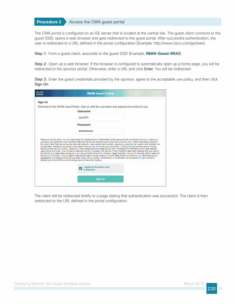
Deploying Remote Site Guest Wireless Access March 2015230
Procedure 3 Access the CWA guest portal
The CWA portal is configured on an ISE server that is located at the central site. The guest client connects to the guest SSID, opens a web browser and gets redirected to the guest portal. After successful authentication, the user is redirected to a URL defined in the portal configuration (Example: http://www.cisco.com/go/iwan).
Step 1: From a guest client, associate to the guest SSID (Example: IWAN-Guest-RS43).
Step 2: Open up a web browser. If the browser is configured to automatically open up a home page, you will be redirected to the sponsor portal. Otherwise, enter a URL and click Enter. You will be redirected.
Step 3: Enter the guest credentials provided by the sponsor, agree to the acceptable use policy, and then click Sign On.
The client will be redirected briefly to a page stating that authentication was successful. The client is then redirected to the URL defined in the portal configuration.
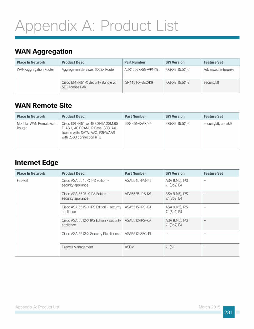
Appendix A: Product List March 2015231
Appendix A: Product ListWAN Aggregation
Place In Network Product Desc. Part Number SW Version Feature Set
WAN-aggregation Router Aggregation Services 1002X Router ASR1002X-5G-VPNK9 IOS-XE 15.5(1)S Advanced Enterprise
Cisco ISR 4451-X Security Bundle w/SEC license PAK
ISR4451-X-SEC/K9 IOS-XE 15.5(1)S securityk9
WAN Remote SitePlace In Network Product Desc. Part Number SW Version Feature Set
Modular WAN Remote-site Router
Cisco ISR 4451 w/ 4GE,3NIM,2SM,8G FLASH, 4G DRAM, IP Base, SEC, AX license with: DATA, AVC, ISR-WAAS with 2500 connection RTU
ISR4451-X-AX/K9 IOS-XE 15.5(1)S securityk9, appxk9
Internet EdgePlace In Network Product Desc. Part Number SW Version Feature Set
Firewall Cisco ASA 5545-X IPS Edition - security appliance
ASA5545-IPS-K9 ASA 9.1(5), IPS 7.1(8p2) E4
—
Cisco ASA 5525-X IPS Edition - security appliance
ASA5525-IPS-K9 ASA 9.1(5), IPS 7.1(8p2) E4
—
Cisco ASA 5515-X IPS Edition - security appliance
ASA5515-IPS-K9 ASA 9.1(5), IPS 7.1(8p2) E4
—
Cisco ASA 5512-X IPS Edition - security appliance
ASA5512-IPS-K9 ASA 9.1(5), IPS 7.1(8p2) E4
—
Cisco ASA 5512-X Security Plus license ASA5512-SEC-PL — —
Firewall Management ASDM 7.1(6) —
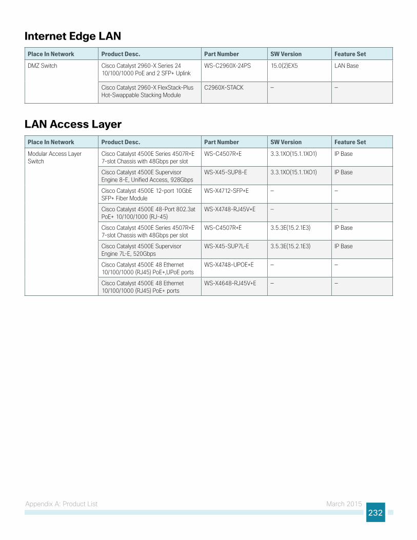
Appendix A: Product List March 2015232
Internet Edge LANPlace In Network Product Desc. Part Number SW Version Feature Set
DMZ Switch Cisco Catalyst 2960-X Series 24 10/100/1000 PoE and 2 SFP+ Uplink
WS-C2960X-24PS 15.0(2)EX5 LAN Base
Cisco Catalyst 2960-X FlexStack-Plus Hot-Swappable Stacking Module
C2960X-STACK — —
LAN Access LayerPlace In Network Product Desc. Part Number SW Version Feature Set
Modular Access Layer Switch
Cisco Catalyst 4500E Series 4507R+E 7-slot Chassis with 48Gbps per slot
WS-C4507R+E 3.3.1XO(15.1.1XO1) IP Base
Cisco Catalyst 4500E Supervisor Engine 8-E, Unified Access, 928Gbps
WS-X45-SUP8-E 3.3.1XO(15.1.1XO1) IP Base
Cisco Catalyst 4500E 12-port 10GbE SFP+ Fiber Module
WS-X4712-SFP+E — —
Cisco Catalyst 4500E 48-Port 802.3at PoE+ 10/100/1000 (RJ-45)
WS-X4748-RJ45V+E — —
Cisco Catalyst 4500E Series 4507R+E 7-slot Chassis with 48Gbps per slot
WS-C4507R+E 3.5.3E(15.2.1E3) IP Base
Cisco Catalyst 4500E Supervisor Engine 7L-E, 520Gbps
WS-X45-SUP7L-E 3.5.3E(15.2.1E3) IP Base
Cisco Catalyst 4500E 48 Ethernet 10/100/1000 (RJ45) PoE+,UPoE ports
WS-X4748-UPOE+E — —
Cisco Catalyst 4500E 48 Ethernet 10/100/1000 (RJ45) PoE+ ports
WS-X4648-RJ45V+E — —
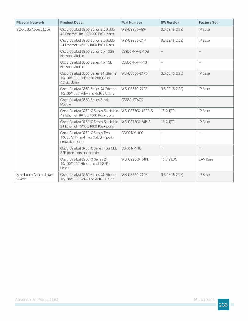
Appendix A: Product List March 2015233
Place In Network Product Desc. Part Number SW Version Feature Set
Stackable Access Layer Cisco Catalyst 3850 Series Stackable 48 Ethernet 10/100/1000 PoE+ ports
WS-C3850-48F 3.6.0E(15.2.2E) IP Base
Cisco Catalyst 3850 Series Stackable 24 Ethernet 10/100/1000 PoE+ Ports
WS-C3850-24P 3.6.0E(15.2.2E) IP Base
Cisco Catalyst 3850 Series 2 x 10GE Network Module
C3850-NM-2-10G — —
Cisco Catalyst 3850 Series 4 x 1GE Network Module
C3850-NM-4-1G — —
Cisco Catalyst 3650 Series 24 Ethernet 10/100/1000 PoE+ and 2x10GE or 4x1GE Uplink
WS-C3650-24PD 3.6.0E(15.2.2E) IP Base
Cisco Catalyst 3650 Series 24 Ethernet 10/100/1000 PoE+ and 4x1GE Uplink
WS-C3650-24PS 3.6.0E(15.2.2E) IP Base
Cisco Catalyst 3650 Series Stack Module
C3650-STACK — —
Cisco Catalyst 3750-X Series Stackable 48 Ethernet 10/100/1000 PoE+ ports
WS-C3750X-48PF-S 15.2(1)E3 IP Base
Cisco Catalyst 3750-X Series Stackable 24 Ethernet 10/100/1000 PoE+ ports
WS-C3750X-24P-S 15.2(1)E3 IP Base
Cisco Catalyst 3750-X Series Two 10GbE SFP+ and Two GbE SFP ports network module
C3KX-NM-10G — —
Cisco Catalyst 3750-X Series Four GbE SFP ports network module
C3KX-NM-1G — —
Cisco Catalyst 2960-X Series 24 10/100/1000 Ethernet and 2 SFP+ Uplink
WS-C2960X-24PD 15.0(2)EX5 LAN Base
Standalone Access Layer Switch
Cisco Catalyst 3650 Series 24 Ethernet 10/100/1000 PoE+ and 4x1GE Uplink
WS-C3650-24PS 3.6.0E(15.2.2E) IP Base
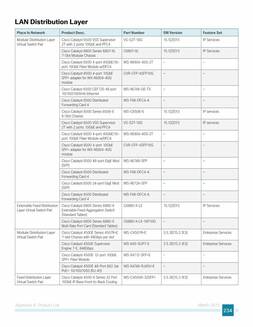
Appendix A: Product List March 2015234
LAN Distribution LayerPlace In Network Product Desc. Part Number SW Version Feature Set
Modular Distribution Layer Virtual Switch Pair
Cisco Catalyst 6500 VSS Supervisor 2T with 2 ports 10GbE and PFC4
VS-S2T-10G 15.1(2)SY3 IP Services
Cisco Catalyst 6800 Series 6807-XL 7-Slot Modular Chassis
C6807-XL 15.1(2)SY3 IP Services
Cisco Catalyst 6500 4-port 40GbE/16-port 10GbE Fiber Module w/DFC4
WS-X6904-40G-2T — —
Cisco Catalyst 6500 4-port 10GbE SFP+ adapter for WX-X6904-40G module
CVR-CFP-4SFP10G — —
Cisco Catalyst 6500 CEF720 48 port 10/100/1000mb Ethernet
WS-X6748-GE-TX — —
Cisco Catalyst 6500 Distributed Forwarding Card 4
WS-F6K-DFC4-A — —
Cisco Catalyst 6500 Series 6506-E 6-Slot Chassis
WS-C6506-E 15.1(2)SY3 IP services
Cisco Catalyst 6500 VSS Supervisor 2T with 2 ports 10GbE and PFC4
VS-S2T-10G 15.1(2)SY3 IP services
Cisco Catalyst 6500 4-port 40GbE/16-port 10GbE Fiber Module w/DFC4
WS-X6904-40G-2T — —
Cisco Catalyst 6500 4-port 10GbE SFP+ adapter for WX-X6904-40G module
CVR-CFP-4SFP10G — —
Cisco Catalyst 6500 48-port GigE Mod (SFP)
WS-X6748-SFP — —
Cisco Catalyst 6500 Distributed Forwarding Card 4
WS-F6K-DFC4-A — —
Cisco Catalyst 6500 24-port GigE Mod (SFP)
WS-X6724-SFP — —
Cisco Catalyst 6500 Distributed Forwarding Card 4
WS-F6K-DFC4-A — —
Extensible Fixed Distribution Layer Virtual Switch Pair
Cisco Catalyst 6800 Series 6880-X Extensible Fixed Aggregation Switch (Standard Tables)
C6880-X-LE 15.1(2)SY3 IP Services
Cisco Catalyst 6800 Series 6880-X Multi Rate Port Card (Standard Tables)
C6880-X-LE-16P10G — —
Modular Distribution Layer Virtual Switch Pair
Cisco Catalyst 4500E Series 4507R+E 7-slot Chassis with 48Gbps per slot
WS-C4507R+E 3.5.3E(15.2.1E3) Enterprise Services
Cisco Catalyst 4500E Supervisor Engine 7-E, 848Gbps
WS-X45-SUP7-E 3.5.3E(15.2.1E3) Enterprise Services
Cisco Catalyst 4500E 12-port 10GbE SFP+ Fiber Module
WS-X4712-SFP+E — —
Cisco Catalyst 4500E 48-Port 802.3at PoE+ 10/100/1000 (RJ-45)
WS-X4748-RJ45V+E — —
Fixed Distribution Layer Virtual Switch Pair
Cisco Catalyst 4500-X Series 32 Port 10GbE IP Base Front-to-Back Cooling
WS-C4500X-32SFP+ 3.5.3E(15.2.1E3) Enterprise Services
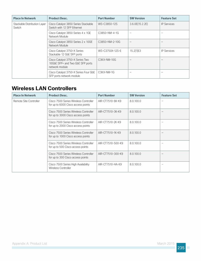
Appendix A: Product List March 2015235
Place In Network Product Desc. Part Number SW Version Feature Set
Stackable Distribution Layer Switch
Cisco Catalyst 3850 Series Stackable Switch with 12 SFP Ethernet
WS-C3850-12S 3.6.0E(15.2.2E) IP Services
Cisco Catalyst 3850 Series 4 x 1GE Network Module
C3850-NM-4-1G — —
Cisco Catalyst 3850 Series 2 x 10GE Network Module
C3850-NM-2-10G — —
Cisco Catalyst 3750-X Series Stackable 12 GbE SFP ports
WS-C3750X-12S-E 15.2(1)E3 IP Services
Cisco Catalyst 3750-X Series Two 10GbE SFP+ and Two GbE SFP ports network module
C3KX-NM-10G — —
Cisco Catalyst 3750-X Series Four GbE SFP ports network module
C3KX-NM-1G — —
Wireless LAN ControllersPlace In Network Product Desc. Part Number SW Version Feature Set
Remote Site Controller Cisco 7500 Series Wireless Controller for up to 6000 Cisco access points
AIR-CT7510-6K-K9 8.0.100.0 —
Cisco 7500 Series Wireless Controller for up to 3000 Cisco access points
AIR-CT7510-3K-K9 8.0.100.0 —
Cisco 7500 Series Wireless Controller for up to 2000 Cisco access points
AIR-CT7510-2K-K9 8.0.100.0 —
Cisco 7500 Series Wireless Controller for up to 1000 Cisco access points
AIR-CT7510-1K-K9 8.0.100.0 —
Cisco 7500 Series Wireless Controller for up to 500 Cisco access points
AIR-CT7510-500-K9 8.0.100.0 —
Cisco 7500 Series Wireless Controller for up to 300 Cisco access points
AIR-CT7510-300-K9 8.0.100.0 —
Cisco 7500 Series High Availability Wireless Controller
AIR-CT7510-HA-K9 8.0.100.0 —
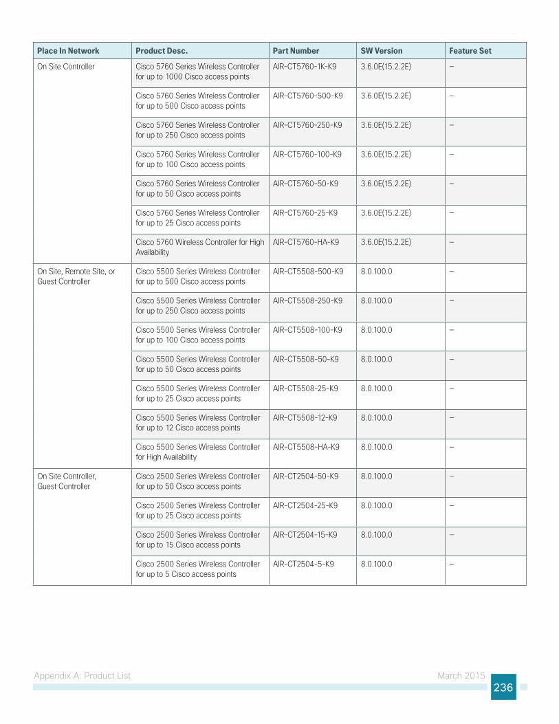
Appendix A: Product List March 2015236
Place In Network Product Desc. Part Number SW Version Feature Set
On Site Controller Cisco 5760 Series Wireless Controller for up to 1000 Cisco access points
AIR-CT5760-1K-K9 3.6.0E(15.2.2E) —
Cisco 5760 Series Wireless Controller for up to 500 Cisco access points
AIR-CT5760-500-K9 3.6.0E(15.2.2E) —
Cisco 5760 Series Wireless Controller for up to 250 Cisco access points
AIR-CT5760-250-K9 3.6.0E(15.2.2E) —
Cisco 5760 Series Wireless Controller for up to 100 Cisco access points
AIR-CT5760-100-K9 3.6.0E(15.2.2E) —
Cisco 5760 Series Wireless Controller for up to 50 Cisco access points
AIR-CT5760-50-K9 3.6.0E(15.2.2E) —
Cisco 5760 Series Wireless Controller for up to 25 Cisco access points
AIR-CT5760-25-K9 3.6.0E(15.2.2E) —
Cisco 5760 Wireless Controller for High Availability
AIR-CT5760-HA-K9 3.6.0E(15.2.2E) —
On Site, Remote Site, or Guest Controller
Cisco 5500 Series Wireless Controller for up to 500 Cisco access points
AIR-CT5508-500-K9 8.0.100.0 —
Cisco 5500 Series Wireless Controller for up to 250 Cisco access points
AIR-CT5508-250-K9 8.0.100.0 —
Cisco 5500 Series Wireless Controller for up to 100 Cisco access points
AIR-CT5508-100-K9 8.0.100.0 —
Cisco 5500 Series Wireless Controller for up to 50 Cisco access points
AIR-CT5508-50-K9 8.0.100.0 —
Cisco 5500 Series Wireless Controller for up to 25 Cisco access points
AIR-CT5508-25-K9 8.0.100.0 —
Cisco 5500 Series Wireless Controller for up to 12 Cisco access points
AIR-CT5508-12-K9 8.0.100.0 —
Cisco 5500 Series Wireless Controller for High Availability
AIR-CT5508-HA-K9 8.0.100.0 —
On Site Controller, Guest Controller
Cisco 2500 Series Wireless Controller for up to 50 Cisco access points
AIR-CT2504-50-K9 8.0.100.0 —
Cisco 2500 Series Wireless Controller for up to 25 Cisco access points
AIR-CT2504-25-K9 8.0.100.0 —
Cisco 2500 Series Wireless Controller for up to 15 Cisco access points
AIR-CT2504-15-K9 8.0.100.0 —
Cisco 2500 Series Wireless Controller for up to 5 Cisco access points
AIR-CT2504-5-K9 8.0.100.0 —
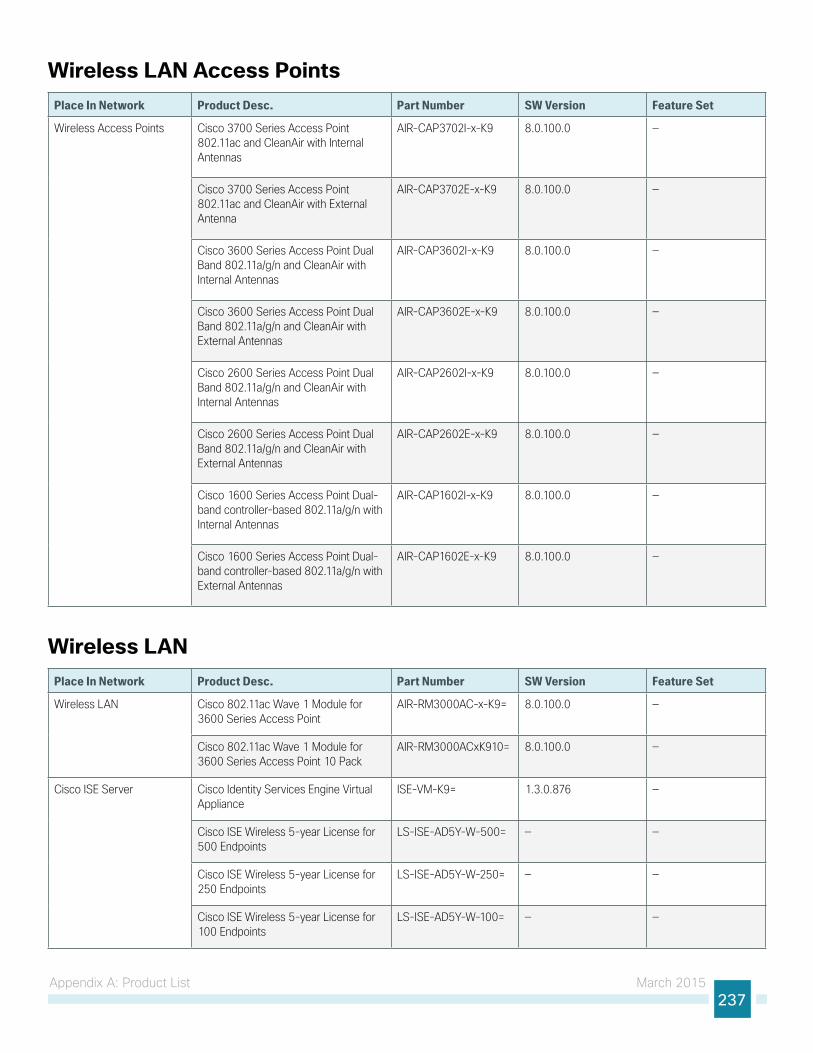
Appendix A: Product List March 2015237
Wireless LAN Access PointsPlace In Network Product Desc. Part Number SW Version Feature Set
Wireless Access Points Cisco 3700 Series Access Point 802.11ac and CleanAir with Internal Antennas
AIR-CAP3702I-x-K9 8.0.100.0 —
Cisco 3700 Series Access Point 802.11ac and CleanAir with External Antenna
AIR-CAP3702E-x-K9 8.0.100.0 —
Cisco 3600 Series Access Point Dual Band 802.11a/g/n and CleanAir with Internal Antennas
AIR-CAP3602I-x-K9 8.0.100.0 —
Cisco 3600 Series Access Point Dual Band 802.11a/g/n and CleanAir with External Antennas
AIR-CAP3602E-x-K9 8.0.100.0 —
Cisco 2600 Series Access Point Dual Band 802.11a/g/n and CleanAir with Internal Antennas
AIR-CAP2602I-x-K9 8.0.100.0 —
Cisco 2600 Series Access Point Dual Band 802.11a/g/n and CleanAir with External Antennas
AIR-CAP2602E-x-K9 8.0.100.0 —
Cisco 1600 Series Access Point Dual-band controller-based 802.11a/g/n with Internal Antennas
AIR-CAP1602I-x-K9 8.0.100.0 —
Cisco 1600 Series Access Point Dual-band controller-based 802.11a/g/n with External Antennas
AIR-CAP1602E-x-K9 8.0.100.0 —
Wireless LANPlace In Network Product Desc. Part Number SW Version Feature Set
Wireless LAN Cisco 802.11ac Wave 1 Module for 3600 Series Access Point
AIR-RM3000AC-x-K9= 8.0.100.0 —
Cisco 802.11ac Wave 1 Module for 3600 Series Access Point 10 Pack
AIR-RM3000ACxK910= 8.0.100.0 —
Cisco ISE Server Cisco Identity Services Engine Virtual Appliance
ISE-VM-K9= 1.3.0.876 —
Cisco ISE Wireless 5-year License for 500 Endpoints
LS-ISE-AD5Y-W-500= — —
Cisco ISE Wireless 5-year License for 250 Endpoints
LS-ISE-AD5Y-W-250= — —
Cisco ISE Wireless 5-year License for 100 Endpoints
LS-ISE-AD5Y-W-100= — —
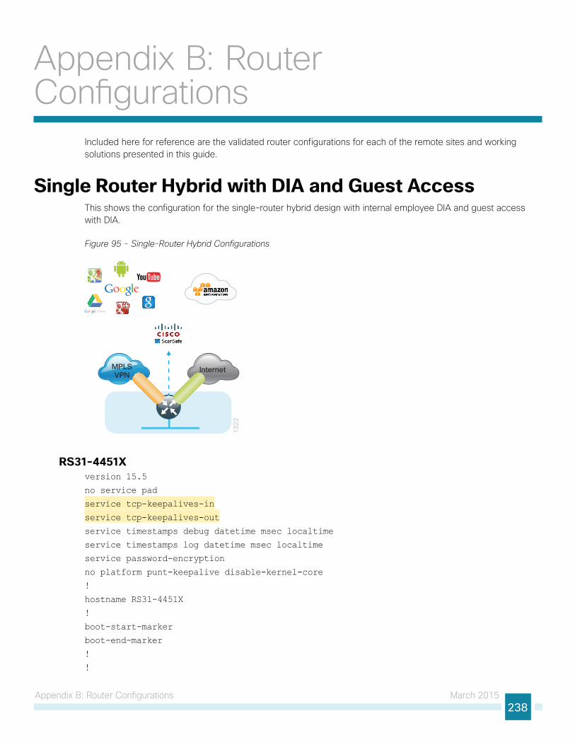
Appendix B: Router Configurations March 2015238
Appendix B: Router Configurations
Included here for reference are the validated router configurations for each of the remote sites and working solutions presented in this guide.
Single Router Hybrid with DIA and Guest AccessThis shows the configuration for the single-router hybrid design with internal employee DIA and guest access with DIA.
Figure 95 - Single-Router Hybrid Configurations
MPLSVPN
Internet
13
22
RS31-4451Xversion 15.5
no service pad
service tcp-keepalives-in
service tcp-keepalives-out
service timestamps debug datetime msec localtime
service timestamps log datetime msec localtime
service password-encryption
no platform punt-keepalive disable-kernel-core
!
hostname RS31-4451X
!
boot-start-marker
boot-end-marker
!
!
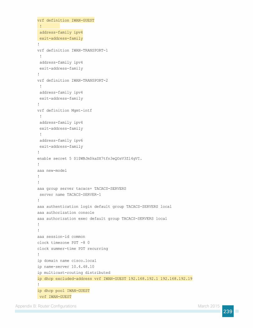
Appendix B: Router Configurations March 2015239
vrf definition IWAN-GUEST
!
address-family ipv4
exit-address-family
!
vrf definition IWAN-TRANSPORT-1
!
address-family ipv4
exit-address-family
!
vrf definition IWAN-TRANSPORT-2
!
address-family ipv4
exit-address-family
!
vrf definition Mgmt-intf
!
address-family ipv4
exit-address-family
!
address-family ipv6
exit-address-family
!
enable secret 5 $1$WBJm$kaSX7tfn3eQOsV3Zl4gVI.
!
aaa new-model
!
!
aaa group server tacacs+ TACACS-SERVERS
server name TACACS-SERVER-1
!
aaa authentication login default group TACACS-SERVERS local
aaa authorization console
aaa authorization exec default group TACACS-SERVERS local
!
!
aaa session-id common
clock timezone PST -8 0
clock summer-time PDT recurring
!
ip domain name cisco.local
ip name-server 10.4.48.10
ip multicast-routing distributed
ip dhcp excluded-address vrf IWAN-GUEST 192.168.192.1 192.168.192.19
!
ip dhcp pool IWAN-GUEST
vrf IWAN-GUEST
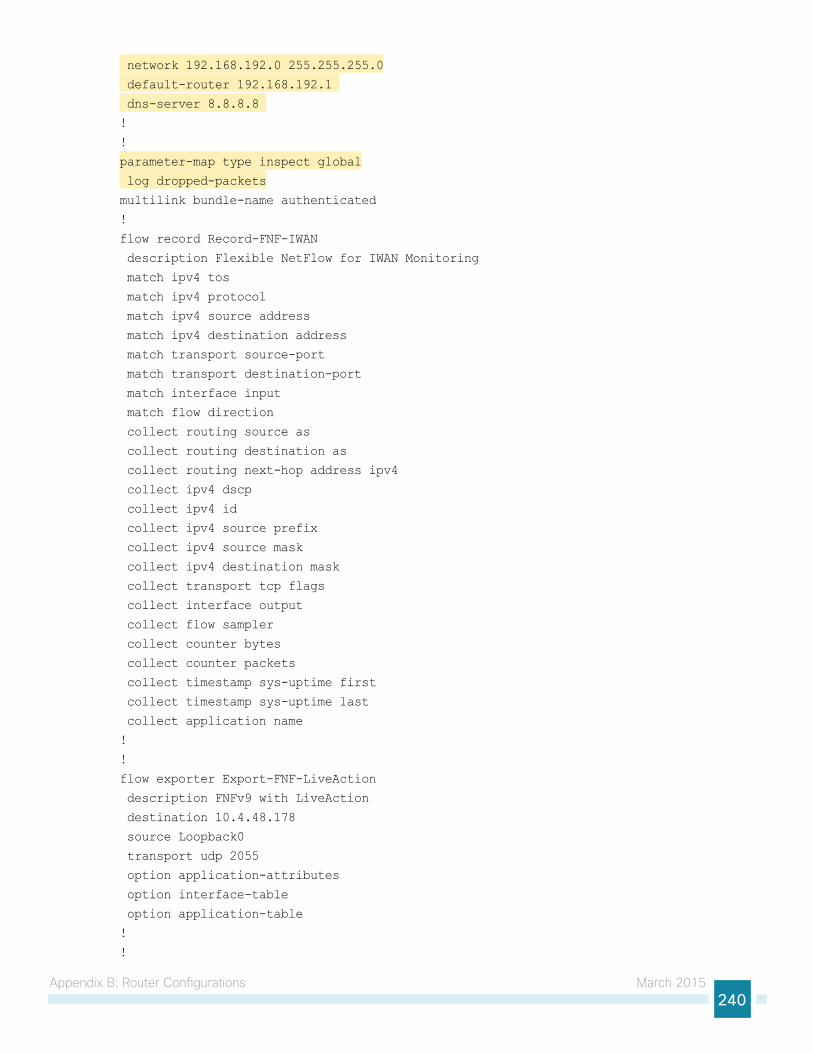
Appendix B: Router Configurations March 2015240
network 192.168.192.0 255.255.255.0
default-router 192.168.192.1
dns-server 8.8.8.8
!
!
parameter-map type inspect global
log dropped-packets
multilink bundle-name authenticated
!
flow record Record-FNF-IWAN
description Flexible NetFlow for IWAN Monitoring
match ipv4 tos
match ipv4 protocol
match ipv4 source address
match ipv4 destination address
match transport source-port
match transport destination-port
match interface input
match flow direction
collect routing source as
collect routing destination as
collect routing next-hop address ipv4
collect ipv4 dscp
collect ipv4 id
collect ipv4 source prefix
collect ipv4 source mask
collect ipv4 destination mask
collect transport tcp flags
collect interface output
collect flow sampler
collect counter bytes
collect counter packets
collect timestamp sys-uptime first
collect timestamp sys-uptime last
collect application name
!
!
flow exporter Export-FNF-LiveAction
description FNFv9 with LiveAction
destination 10.4.48.178
source Loopback0
transport udp 2055
option application-attributes
option interface-table
option application-table
!
!
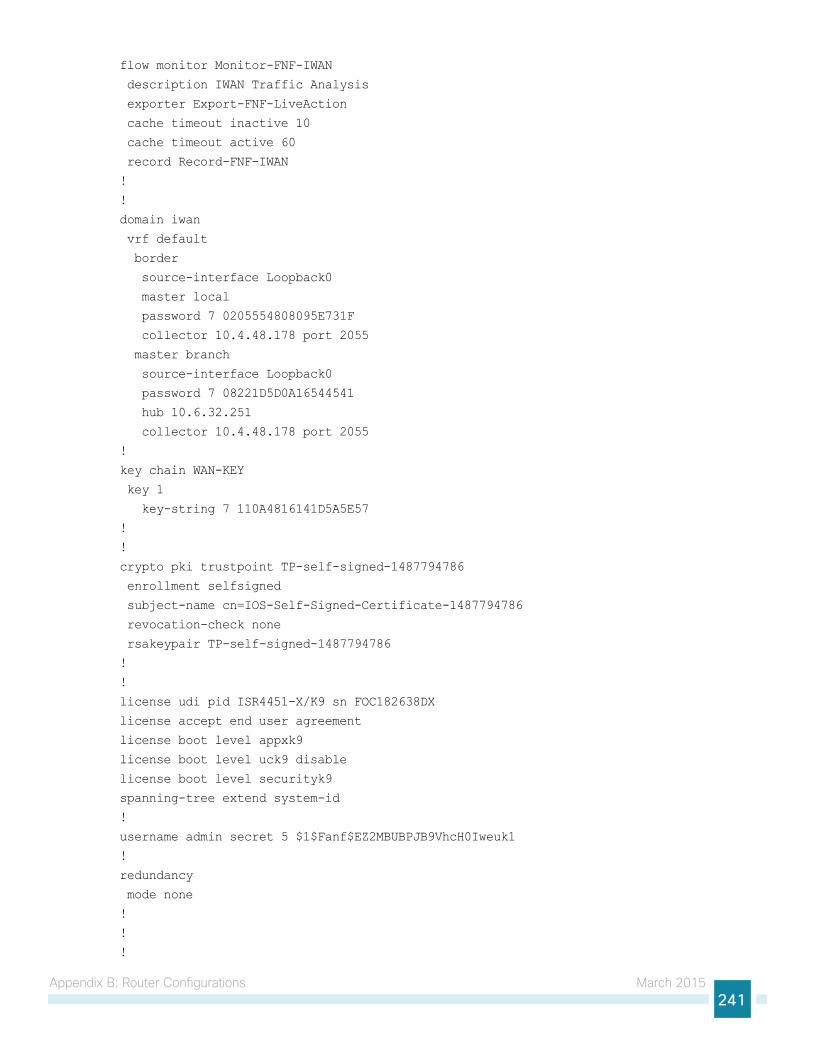
Appendix B: Router Configurations March 2015241
flow monitor Monitor-FNF-IWAN
description IWAN Traffic Analysis
exporter Export-FNF-LiveAction
cache timeout inactive 10
cache timeout active 60
record Record-FNF-IWAN
!
!
domain iwan
vrf default
border
source-interface Loopback0
master local
password 7 0205554808095E731F
collector 10.4.48.178 port 2055
master branch
source-interface Loopback0
password 7 08221D5D0A16544541
hub 10.6.32.251
collector 10.4.48.178 port 2055
!
key chain WAN-KEY
key 1
key-string 7 110A4816141D5A5E57
!
!
crypto pki trustpoint TP-self-signed-1487794786
enrollment selfsigned
subject-name cn=IOS-Self-Signed-Certificate-1487794786
revocation-check none
rsakeypair TP-self-signed-1487794786
!
!
license udi pid ISR4451-X/K9 sn FOC182638DX
license accept end user agreement
license boot level appxk9
license boot level uck9 disable
license boot level securityk9
spanning-tree extend system-id
!
username admin secret 5 $1$Fanf$EZ2MBUBPJB9VhcH0Iweuk1
!
redundancy
mode none
!
!
!
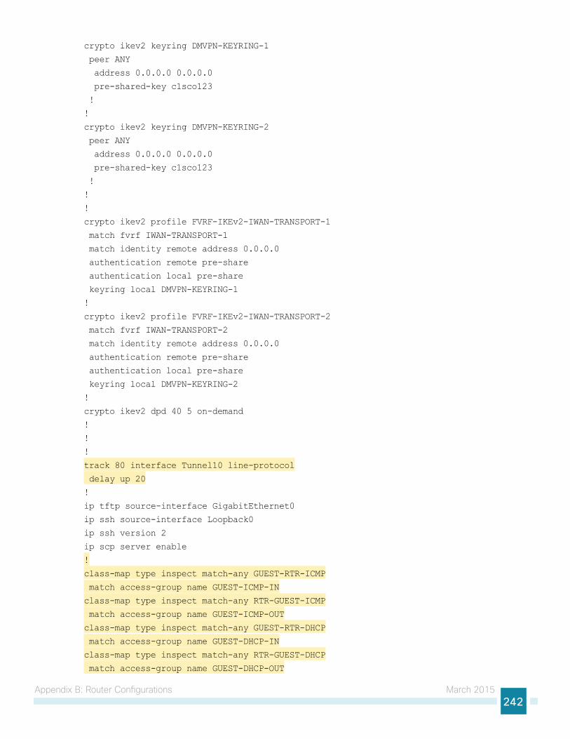
Appendix B: Router Configurations March 2015242
crypto ikev2 keyring DMVPN-KEYRING-1
peer ANY
address 0.0.0.0 0.0.0.0
pre-shared-key c1sco123
!
!
crypto ikev2 keyring DMVPN-KEYRING-2
peer ANY
address 0.0.0.0 0.0.0.0
pre-shared-key c1sco123
!
!
!
crypto ikev2 profile FVRF-IKEv2-IWAN-TRANSPORT-1
match fvrf IWAN-TRANSPORT-1
match identity remote address 0.0.0.0
authentication remote pre-share
authentication local pre-share
keyring local DMVPN-KEYRING-1
!
crypto ikev2 profile FVRF-IKEv2-IWAN-TRANSPORT-2
match fvrf IWAN-TRANSPORT-2
match identity remote address 0.0.0.0
authentication remote pre-share
authentication local pre-share
keyring local DMVPN-KEYRING-2
!
crypto ikev2 dpd 40 5 on-demand
!
!
!
track 80 interface Tunnel10 line-protocol
delay up 20
!
ip tftp source-interface GigabitEthernet0
ip ssh source-interface Loopback0
ip ssh version 2
ip scp server enable
!
class-map type inspect match-any GUEST-RTR-ICMP
match access-group name GUEST-ICMP-IN
class-map type inspect match-any RTR-GUEST-ICMP
match access-group name GUEST-ICMP-OUT
class-map type inspect match-any GUEST-RTR-DHCP
match access-group name GUEST-DHCP-IN
class-map type inspect match-any RTR-GUEST-DHCP
match access-group name GUEST-DHCP-OUT
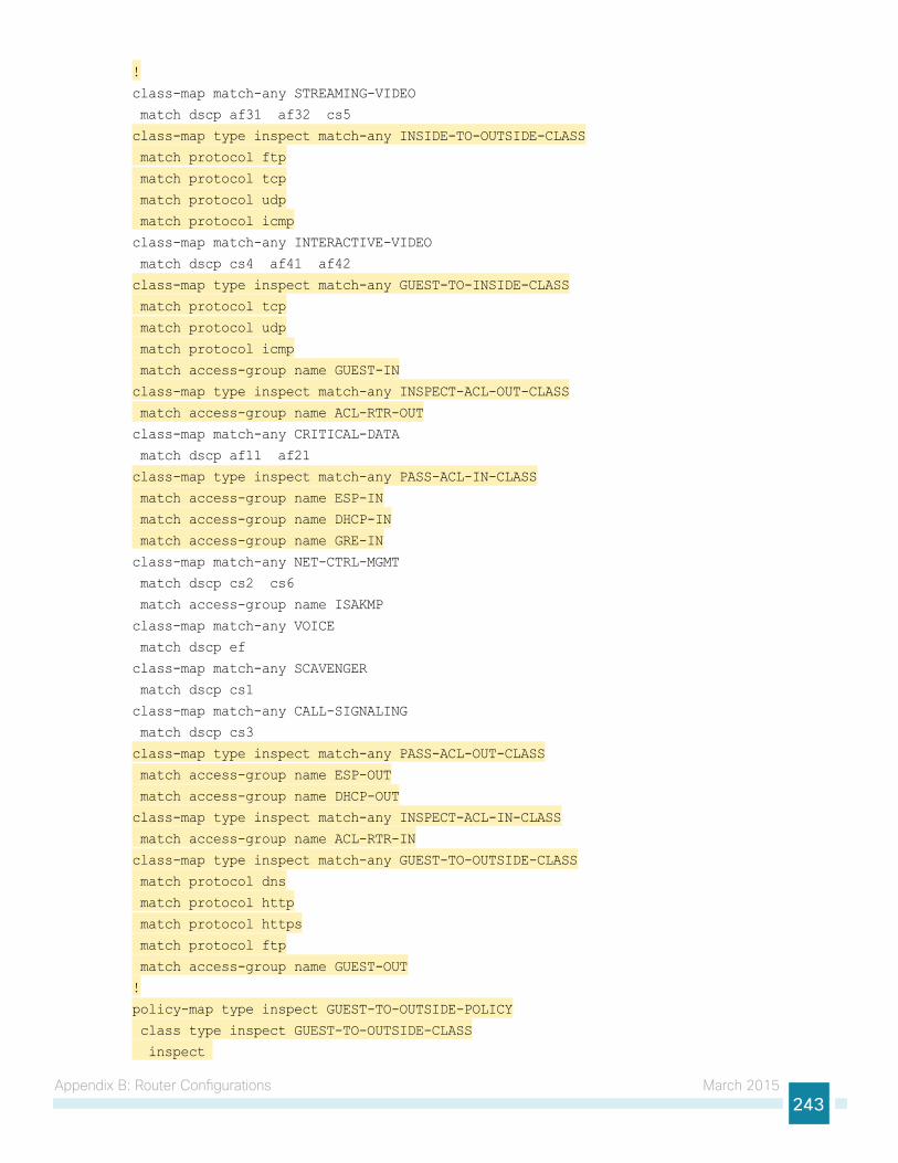
Appendix B: Router Configurations March 2015243
!
class-map match-any STREAMING-VIDEO
match dscp af31 af32 cs5
class-map type inspect match-any INSIDE-TO-OUTSIDE-CLASS
match protocol ftp
match protocol tcp
match protocol udp
match protocol icmp
class-map match-any INTERACTIVE-VIDEO
match dscp cs4 af41 af42
class-map type inspect match-any GUEST-TO-INSIDE-CLASS
match protocol tcp
match protocol udp
match protocol icmp
match access-group name GUEST-IN
class-map type inspect match-any INSPECT-ACL-OUT-CLASS
match access-group name ACL-RTR-OUT
class-map match-any CRITICAL-DATA
match dscp af11 af21
class-map type inspect match-any PASS-ACL-IN-CLASS
match access-group name ESP-IN
match access-group name DHCP-IN
match access-group name GRE-IN
class-map match-any NET-CTRL-MGMT
match dscp cs2 cs6
match access-group name ISAKMP
class-map match-any VOICE
match dscp ef
class-map match-any SCAVENGER
match dscp cs1
class-map match-any CALL-SIGNALING
match dscp cs3
class-map type inspect match-any PASS-ACL-OUT-CLASS
match access-group name ESP-OUT
match access-group name DHCP-OUT
class-map type inspect match-any INSPECT-ACL-IN-CLASS
match access-group name ACL-RTR-IN
class-map type inspect match-any GUEST-TO-OUTSIDE-CLASS
match protocol dns
match protocol http
match protocol https
match protocol ftp
match access-group name GUEST-OUT
!
policy-map type inspect GUEST-TO-OUTSIDE-POLICY
class type inspect GUEST-TO-OUTSIDE-CLASS
inspect
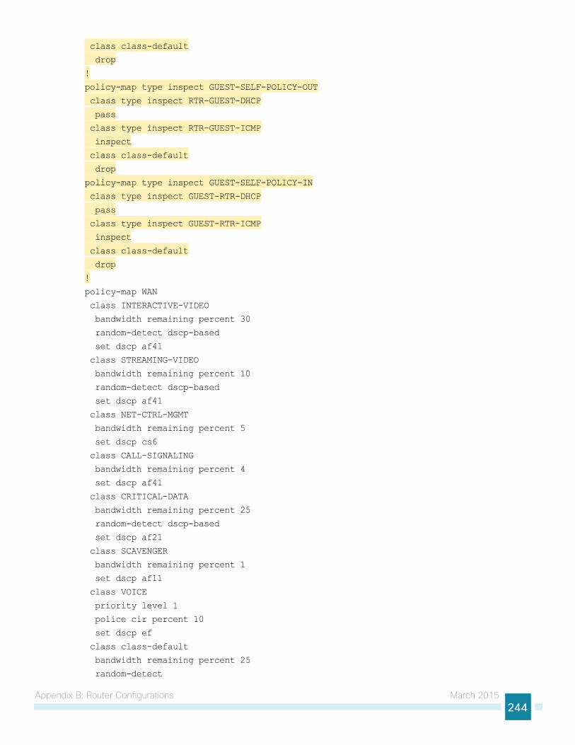
Appendix B: Router Configurations March 2015244
class class-default
drop
!
policy-map type inspect GUEST-SELF-POLICY-OUT
class type inspect RTR-GUEST-DHCP
pass
class type inspect RTR-GUEST-ICMP
inspect
class class-default
drop
policy-map type inspect GUEST-SELF-POLICY-IN
class type inspect GUEST-RTR-DHCP
pass
class type inspect GUEST-RTR-ICMP
inspect
class class-default
drop
!
policy-map WAN
class INTERACTIVE-VIDEO
bandwidth remaining percent 30
random-detect dscp-based
set dscp af41
class STREAMING-VIDEO
bandwidth remaining percent 10
random-detect dscp-based
set dscp af41
class NET-CTRL-MGMT
bandwidth remaining percent 5
set dscp cs6
class CALL-SIGNALING
bandwidth remaining percent 4
set dscp af41
class CRITICAL-DATA
bandwidth remaining percent 25
random-detect dscp-based
set dscp af21
class SCAVENGER
bandwidth remaining percent 1
set dscp af11
class VOICE
priority level 1
police cir percent 10
set dscp ef
class class-default
bandwidth remaining percent 25
random-detect
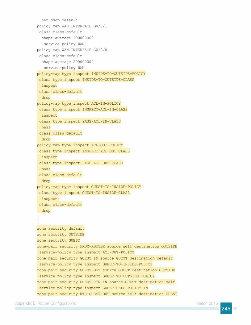
Appendix B: Router Configurations March 2015245
set dscp default
policy-map WAN-INTERFACE-G0/0/1
class class-default
shape average 100000000
service-policy WAN
policy-map WAN-INTERFACE-G0/0/0
class class-default
shape average 200000000
service-policy WAN
policy-map type inspect INSIDE-TO-OUTSIDE-POLICY
class type inspect INSIDE-TO-OUTSIDE-CLASS
inspect
class class-default
drop
policy-map type inspect ACL-IN-POLICY
class type inspect INSPECT-ACL-IN-CLASS
inspect
class type inspect PASS-ACL-IN-CLASS
pass
class class-default
drop
policy-map type inspect ACL-OUT-POLICY
class type inspect INSPECT-ACL-OUT-CLASS
inspect
class type inspect PASS-ACL-OUT-CLASS
pass
class class-default
drop
policy-map type inspect GUEST-TO-INSIDE-POLICY
class type inspect GUEST-TO-INSIDE-CLASS
inspect
class class-default
drop
!
!
zone security default
zone security OUTSIDE
zone security GUEST
zone-pair security FROM-ROUTER source self destination OUTSIDE
service-policy type inspect ACL-OUT-POLICY
zone-pair security GUEST-IN source GUEST destination default
service-policy type inspect GUEST-TO-INSIDE-POLICY
zone-pair security GUEST-OUT source GUEST destination OUTSIDE
service-policy type inspect GUEST-TO-OUTSIDE-POLICY
zone-pair security GUEST-RTR-IN source GUEST destination self
service-policy type inspect GUEST-SELF-POLICY-IN
zone-pair security RTR-GUEST-OUT source self destination GUEST
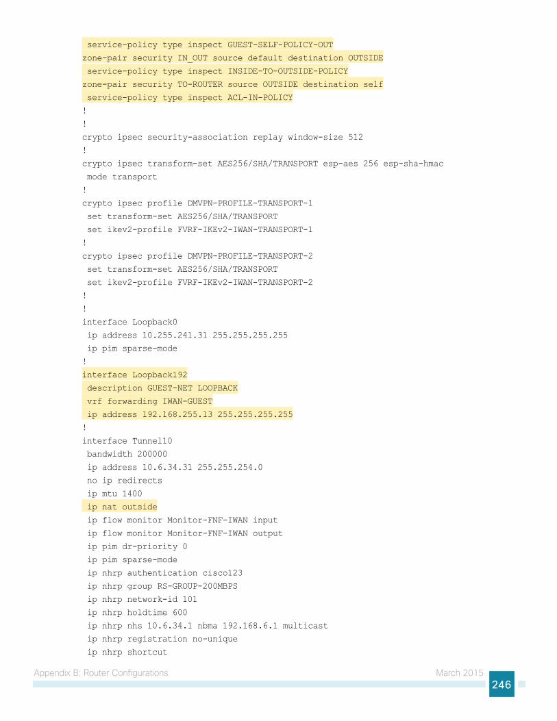
Appendix B: Router Configurations March 2015246
service-policy type inspect GUEST-SELF-POLICY-OUT
zone-pair security IN_OUT source default destination OUTSIDE
service-policy type inspect INSIDE-TO-OUTSIDE-POLICY
zone-pair security TO-ROUTER source OUTSIDE destination self
service-policy type inspect ACL-IN-POLICY
!
!
crypto ipsec security-association replay window-size 512
!
crypto ipsec transform-set AES256/SHA/TRANSPORT esp-aes 256 esp-sha-hmac
mode transport
!
crypto ipsec profile DMVPN-PROFILE-TRANSPORT-1
set transform-set AES256/SHA/TRANSPORT
set ikev2-profile FVRF-IKEv2-IWAN-TRANSPORT-1
!
crypto ipsec profile DMVPN-PROFILE-TRANSPORT-2
set transform-set AES256/SHA/TRANSPORT
set ikev2-profile FVRF-IKEv2-IWAN-TRANSPORT-2
!
!
interface Loopback0
ip address 10.255.241.31 255.255.255.255
ip pim sparse-mode
!
interface Loopback192
description GUEST-NET LOOPBACK
vrf forwarding IWAN-GUEST
ip address 192.168.255.13 255.255.255.255
!
interface Tunnel10
bandwidth 200000
ip address 10.6.34.31 255.255.254.0
no ip redirects
ip mtu 1400
ip nat outside
ip flow monitor Monitor-FNF-IWAN input
ip flow monitor Monitor-FNF-IWAN output
ip pim dr-priority 0
ip pim sparse-mode
ip nhrp authentication cisco123
ip nhrp group RS-GROUP-200MBPS
ip nhrp network-id 101
ip nhrp holdtime 600
ip nhrp nhs 10.6.34.1 nbma 192.168.6.1 multicast
ip nhrp registration no-unique
ip nhrp shortcut
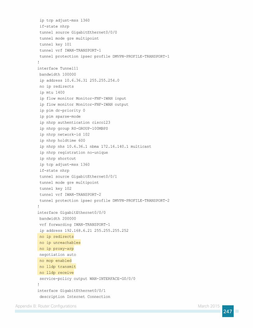
Appendix B: Router Configurations March 2015247
ip tcp adjust-mss 1360
if-state nhrp
tunnel source GigabitEthernet0/0/0
tunnel mode gre multipoint
tunnel key 101
tunnel vrf IWAN-TRANSPORT-1
tunnel protection ipsec profile DMVPN-PROFILE-TRANSPORT-1
!
interface Tunnel11
bandwidth 100000
ip address 10.6.36.31 255.255.254.0
no ip redirects
ip mtu 1400
ip flow monitor Monitor-FNF-IWAN input
ip flow monitor Monitor-FNF-IWAN output
ip pim dr-priority 0
ip pim sparse-mode
ip nhrp authentication cisco123
ip nhrp group RS-GROUP-100MBPS
ip nhrp network-id 102
ip nhrp holdtime 600
ip nhrp nhs 10.6.36.1 nbma 172.16.140.1 multicast
ip nhrp registration no-unique
ip nhrp shortcut
ip tcp adjust-mss 1360
if-state nhrp
tunnel source GigabitEthernet0/0/1
tunnel mode gre multipoint
tunnel key 102
tunnel vrf IWAN-TRANSPORT-2
tunnel protection ipsec profile DMVPN-PROFILE-TRANSPORT-2
!
interface GigabitEthernet0/0/0
bandwidth 200000
vrf forwarding IWAN-TRANSPORT-1
ip address 192.168.6.21 255.255.255.252
no ip redirects
no ip unreachables
no ip proxy-arp
negotiation auto
no mop enabled
no lldp transmit
no lldp receive
service-policy output WAN-INTERFACE-G0/0/0
!
interface GigabitEthernet0/0/1
description Internet Connection
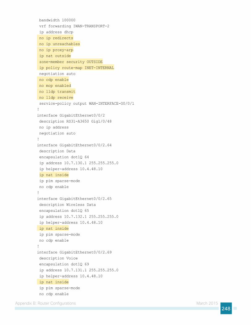
Appendix B: Router Configurations March 2015248
bandwidth 100000
vrf forwarding IWAN-TRANSPORT-2
ip address dhcp
no ip redirects
no ip unreachables
no ip proxy-arp
ip nat outside
zone-member security OUTSIDE
ip policy route-map INET-INTERNAL
negotiation auto
no cdp enable
no mop enabled
no lldp transmit
no lldp receive
service-policy output WAN-INTERFACE-G0/0/1
!
interface GigabitEthernet0/0/2
description RS31-A3650 Gig1/0/48
no ip address
negotiation auto
!
interface GigabitEthernet0/0/2.64
description Data
encapsulation dot1Q 64
ip address 10.7.130.1 255.255.255.0
ip helper-address 10.4.48.10
ip nat inside
ip pim sparse-mode
no cdp enable
!
interface GigabitEthernet0/0/2.65
description Wireless Data
encapsulation dot1Q 65
ip address 10.7.132.1 255.255.255.0
ip helper-address 10.4.48.10
ip nat inside
ip pim sparse-mode
no cdp enable
!
interface GigabitEthernet0/0/2.69
description Voice
encapsulation dot1Q 69
ip address 10.7.131.1 255.255.255.0
ip helper-address 10.4.48.10
ip nat inside
ip pim sparse-mode
no cdp enable
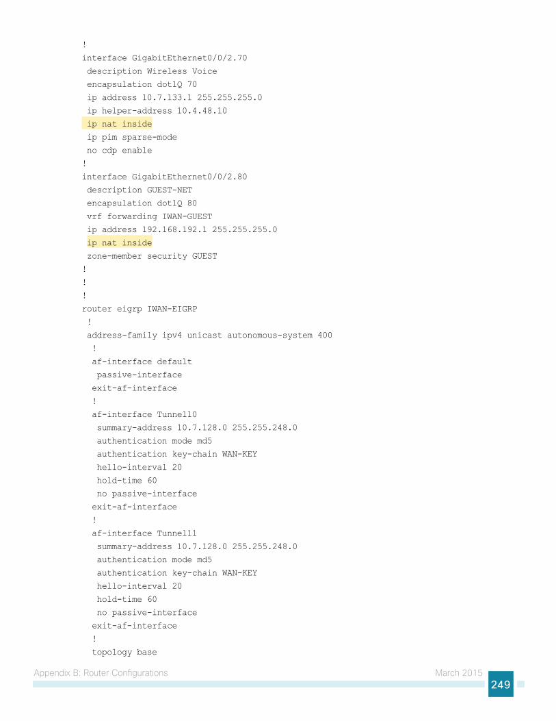
Appendix B: Router Configurations March 2015249
!
interface GigabitEthernet0/0/2.70
description Wireless Voice
encapsulation dot1Q 70
ip address 10.7.133.1 255.255.255.0
ip helper-address 10.4.48.10
ip nat inside
ip pim sparse-mode
no cdp enable
!
interface GigabitEthernet0/0/2.80
description GUEST-NET
encapsulation dot1Q 80
vrf forwarding IWAN-GUEST
ip address 192.168.192.1 255.255.255.0
ip nat inside
zone-member security GUEST
!
!
!
router eigrp IWAN-EIGRP
!
address-family ipv4 unicast autonomous-system 400
!
af-interface default
passive-interface
exit-af-interface
!
af-interface Tunnel10
summary-address 10.7.128.0 255.255.248.0
authentication mode md5
authentication key-chain WAN-KEY
hello-interval 20
hold-time 60
no passive-interface
exit-af-interface
!
af-interface Tunnel11
summary-address 10.7.128.0 255.255.248.0
authentication mode md5
authentication key-chain WAN-KEY
hello-interval 20
hold-time 60
no passive-interface
exit-af-interface
!
topology base
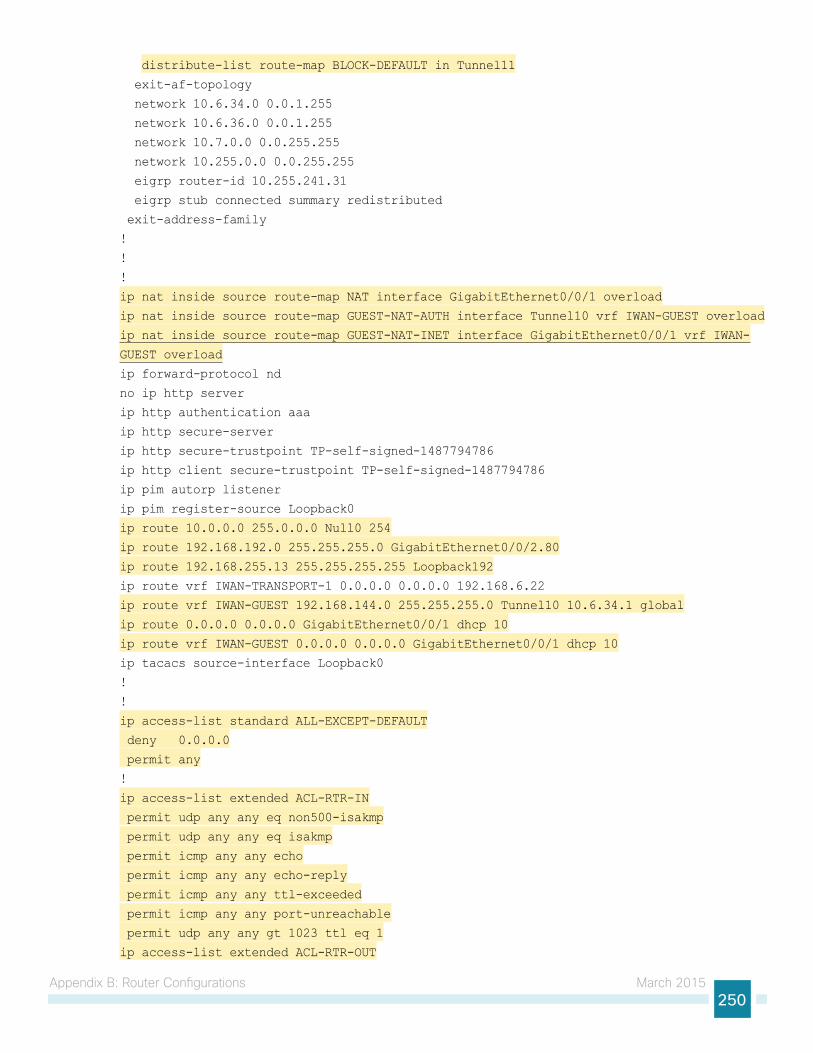
Appendix B: Router Configurations March 2015250
distribute-list route-map BLOCK-DEFAULT in Tunnel11
exit-af-topology
network 10.6.34.0 0.0.1.255
network 10.6.36.0 0.0.1.255
network 10.7.0.0 0.0.255.255
network 10.255.0.0 0.0.255.255
eigrp router-id 10.255.241.31
eigrp stub connected summary redistributed
exit-address-family
!
!
!
ip nat inside source route-map NAT interface GigabitEthernet0/0/1 overload
ip nat inside source route-map GUEST-NAT-AUTH interface Tunnel10 vrf IWAN-GUEST overload
ip nat inside source route-map GUEST-NAT-INET interface GigabitEthernet0/0/1 vrf IWAN-
GUEST overload
ip forward-protocol nd
no ip http server
ip http authentication aaa
ip http secure-server
ip http secure-trustpoint TP-self-signed-1487794786
ip http client secure-trustpoint TP-self-signed-1487794786
ip pim autorp listener
ip pim register-source Loopback0
ip route 10.0.0.0 255.0.0.0 Null0 254
ip route 192.168.192.0 255.255.255.0 GigabitEthernet0/0/2.80
ip route 192.168.255.13 255.255.255.255 Loopback192
ip route vrf IWAN-TRANSPORT-1 0.0.0.0 0.0.0.0 192.168.6.22
ip route vrf IWAN-GUEST 192.168.144.0 255.255.255.0 Tunnel10 10.6.34.1 global
ip route 0.0.0.0 0.0.0.0 GigabitEthernet0/0/1 dhcp 10
ip route vrf IWAN-GUEST 0.0.0.0 0.0.0.0 GigabitEthernet0/0/1 dhcp 10
ip tacacs source-interface Loopback0
!
!
ip access-list standard ALL-EXCEPT-DEFAULT
deny 0.0.0.0
permit any
!
ip access-list extended ACL-RTR-IN
permit udp any any eq non500-isakmp
permit udp any any eq isakmp
permit icmp any any echo
permit icmp any any echo-reply
permit icmp any any ttl-exceeded
permit icmp any any port-unreachable
permit udp any any gt 1023 ttl eq 1
ip access-list extended ACL-RTR-OUT

Appendix B: Router Configurations March 2015251
permit udp any any eq non500-isakmp
permit udp any any eq isakmp
permit icmp any any
permit udp any any eq domain
ip access-list extended DHCP-IN
permit udp any eq bootps any eq bootpc
ip access-list extended DHCP-OUT
permit udp any eq bootpc any eq bootps
ip access-list extended ESP-IN
permit esp any any
ip access-list extended ESP-OUT
permit esp any any
ip access-list extended GRE-IN
permit gre any any
ip access-list extended GUEST-AUTH
permit ip 192.168.192.0 0.0.0.255 192.168.144.0 0.0.0.255
ip access-list extended GUEST-DHCP-IN
permit udp any eq bootpc any eq bootps
ip access-list extended GUEST-DHCP-OUT
permit udp any eq bootps any eq bootpc
ip access-list extended GUEST-ICMP-IN
permit icmp any any echo
permit icmp any any echo-reply
ip access-list extended GUEST-ICMP-OUT
permit icmp any any echo
permit icmp any any echo-reply
ip access-list extended GUEST-IN
permit ip 192.168.192.0 0.0.0.255 192.168.144.0 0.0.0.255
ip access-list extended GUEST-INET
deny ip 192.168.192.0 0.0.0.255 192.168.144.0 0.0.0.255
permit ip 192.168.192.0 0.0.0.255 any
ip access-list extended GUEST-OUT
permit ip 192.168.192.0 0.0.0.255 any
ip access-list extended ISAKMP
permit udp any eq isakmp any eq isakmp
ip access-list extended NAT-LOCAL
permit ip 10.7.128.0 0.0.7.255 any
!
no service-routing capabilities-manager
!
route-map GUEST-NAT-AUTH permit 10
match ip address GUEST-AUTH
match interface Tunnel10
!
route-map GUEST-NAT-INET permit 10
match ip address GUEST-INET
match interface GigabitEthernet0/0/1
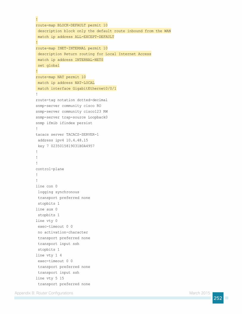
Appendix B: Router Configurations March 2015252
!
route-map BLOCK-DEFAULT permit 10
description block only the default route inbound from the WAN
match ip address ALL-EXCEPT-DEFAULT
!
route-map INET-INTERNAL permit 10
description Return routing for Local Internet Access
match ip address INTERNAL-NETS
set global
!
route-map NAT permit 10
match ip address NAT-LOCAL
match interface GigabitEthernet0/0/1
!
route-tag notation dotted-decimal
snmp-server community cisco RO
snmp-server community cisco123 RW
snmp-server trap-source Loopback0
snmp ifmib ifindex persist
!
tacacs server TACACS-SERVER-1
address ipv4 10.4.48.15
key 7 0235015819031B0A4957
!
!
!
control-plane
!
!
line con 0
logging synchronous
transport preferred none
stopbits 1
line aux 0
stopbits 1
line vty 0
exec-timeout 0 0
no activation-character
transport preferred none
transport input ssh
stopbits 1
line vty 1 4
exec-timeout 0 0
transport preferred none
transport input ssh
line vty 5 15
transport preferred none
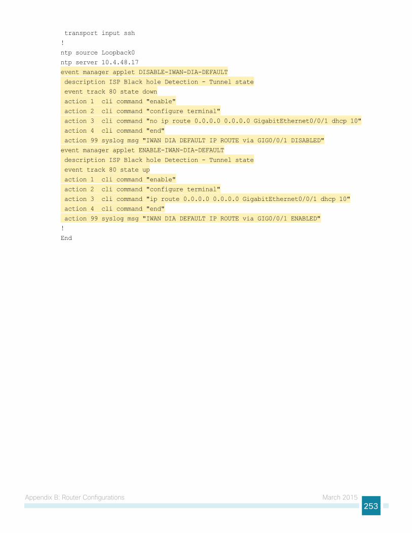
Appendix B: Router Configurations March 2015253
transport input ssh
!
ntp source Loopback0
ntp server 10.4.48.17
event manager applet DISABLE-IWAN-DIA-DEFAULT
description ISP Black hole Detection - Tunnel state
event track 80 state down
action 1 cli command "enable"
action 2 cli command "configure terminal"
action 3 cli command "no ip route 0.0.0.0 0.0.0.0 GigabitEthernet0/0/1 dhcp 10"
action 4 cli command "end"
action 99 syslog msg "IWAN DIA DEFAULT IP ROUTE via GIG0/0/1 DISABLED"
event manager applet ENABLE-IWAN-DIA-DEFAULT
description ISP Black hole Detection - Tunnel state
event track 80 state up
action 1 cli command "enable"
action 2 cli command "configure terminal"
action 3 cli command "ip route 0.0.0.0 0.0.0.0 GigabitEthernet0/0/1 dhcp 10"
action 4 cli command "end"
action 99 syslog msg "IWAN DIA DEFAULT IP ROUTE via GIG0/0/1 ENABLED"
!
End
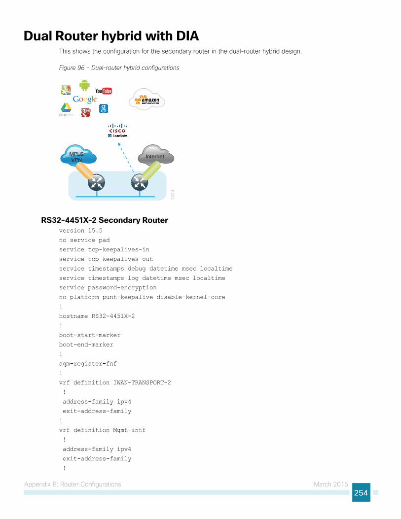
Appendix B: Router Configurations March 2015254
Dual Router hybrid with DIAThis shows the configuration for the secondary router in the dual-router hybrid design.
Figure 96 - Dual-router hybrid configurations
13
24
InternetMPLSVPN
RS32-4451X-2 Secondary Routerversion 15.5
no service pad
service tcp-keepalives-in
service tcp-keepalives-out
service timestamps debug datetime msec localtime
service timestamps log datetime msec localtime
service password-encryption
no platform punt-keepalive disable-kernel-core
!
hostname RS32-4451X-2
!
boot-start-marker
boot-end-marker
!
aqm-register-fnf
!
vrf definition IWAN-TRANSPORT-2
!
address-family ipv4
exit-address-family
!
vrf definition Mgmt-intf
!
address-family ipv4
exit-address-family
!
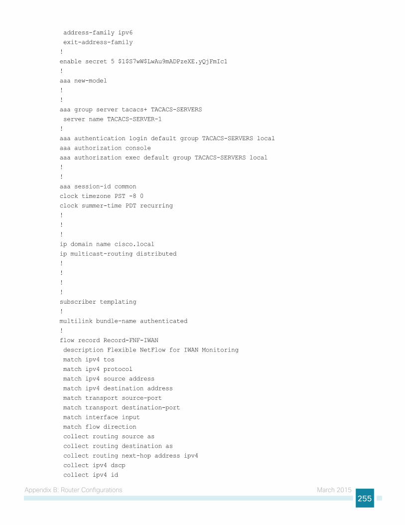
Appendix B: Router Configurations March 2015255
address-family ipv6
exit-address-family
!
enable secret 5 $1$S7wW$LwAu9mADPzeXE.yQjFmIc1
!
aaa new-model
!
!
aaa group server tacacs+ TACACS-SERVERS
server name TACACS-SERVER-1
!
aaa authentication login default group TACACS-SERVERS local
aaa authorization console
aaa authorization exec default group TACACS-SERVERS local
!
!
aaa session-id common
clock timezone PST -8 0
clock summer-time PDT recurring
!
!
!
ip domain name cisco.local
ip multicast-routing distributed
!
!
!
!
subscriber templating
!
multilink bundle-name authenticated
!
flow record Record-FNF-IWAN
description Flexible NetFlow for IWAN Monitoring
match ipv4 tos
match ipv4 protocol
match ipv4 source address
match ipv4 destination address
match transport source-port
match transport destination-port
match interface input
match flow direction
collect routing source as
collect routing destination as
collect routing next-hop address ipv4
collect ipv4 dscp
collect ipv4 id
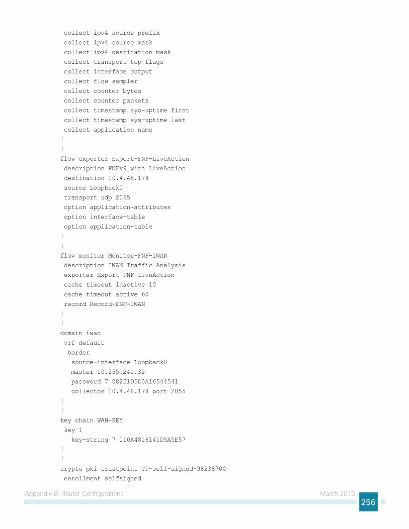
Appendix B: Router Configurations March 2015256
collect ipv4 source prefix
collect ipv4 source mask
collect ipv4 destination mask
collect transport tcp flags
collect interface output
collect flow sampler
collect counter bytes
collect counter packets
collect timestamp sys-uptime first
collect timestamp sys-uptime last
collect application name
!
!
flow exporter Export-FNF-LiveAction
description FNFv9 with LiveAction
destination 10.4.48.178
source Loopback0
transport udp 2055
option application-attributes
option interface-table
option application-table
!
!
flow monitor Monitor-FNF-IWAN
description IWAN Traffic Analysis
exporter Export-FNF-LiveAction
cache timeout inactive 10
cache timeout active 60
record Record-FNF-IWAN
!
!
domain iwan
vrf default
border
source-interface Loopback0
master 10.255.241.32
password 7 08221D5D0A16544541
collector 10.4.48.178 port 2055
!
!
key chain WAN-KEY
key 1
key-string 7 110A4816141D5A5E57
!
!
crypto pki trustpoint TP-self-signed-98238700
enrollment selfsigned
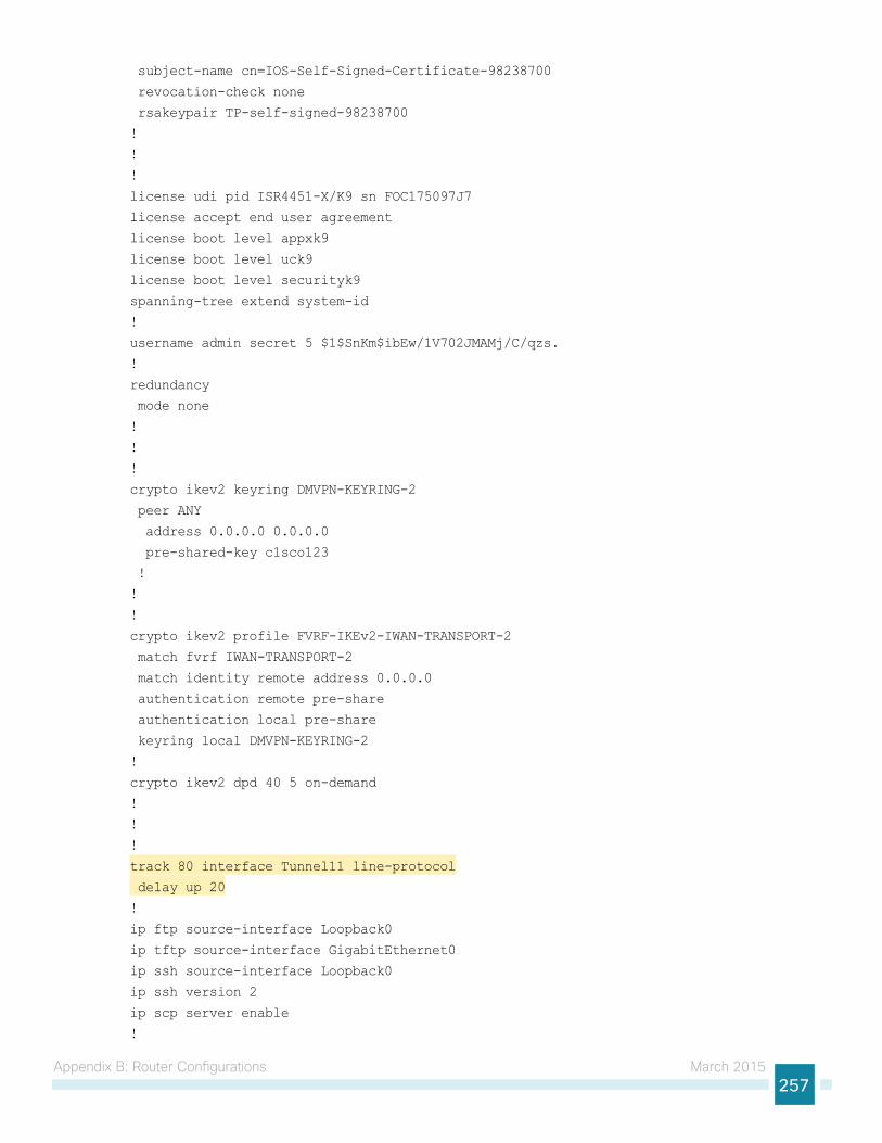
Appendix B: Router Configurations March 2015257
subject-name cn=IOS-Self-Signed-Certificate-98238700
revocation-check none
rsakeypair TP-self-signed-98238700
!
!
!
license udi pid ISR4451-X/K9 sn FOC175097J7
license accept end user agreement
license boot level appxk9
license boot level uck9
license boot level securityk9
spanning-tree extend system-id
!
username admin secret 5 $1$SnKm$ibEw/1V702JMAMj/C/qzs.
!
redundancy
mode none
!
!
!
crypto ikev2 keyring DMVPN-KEYRING-2
peer ANY
address 0.0.0.0 0.0.0.0
pre-shared-key c1sco123
!
!
!
crypto ikev2 profile FVRF-IKEv2-IWAN-TRANSPORT-2
match fvrf IWAN-TRANSPORT-2
match identity remote address 0.0.0.0
authentication remote pre-share
authentication local pre-share
keyring local DMVPN-KEYRING-2
!
crypto ikev2 dpd 40 5 on-demand
!
!
!
track 80 interface Tunnel11 line-protocol
delay up 20
!
ip ftp source-interface Loopback0
ip tftp source-interface GigabitEthernet0
ip ssh source-interface Loopback0
ip ssh version 2
ip scp server enable
!
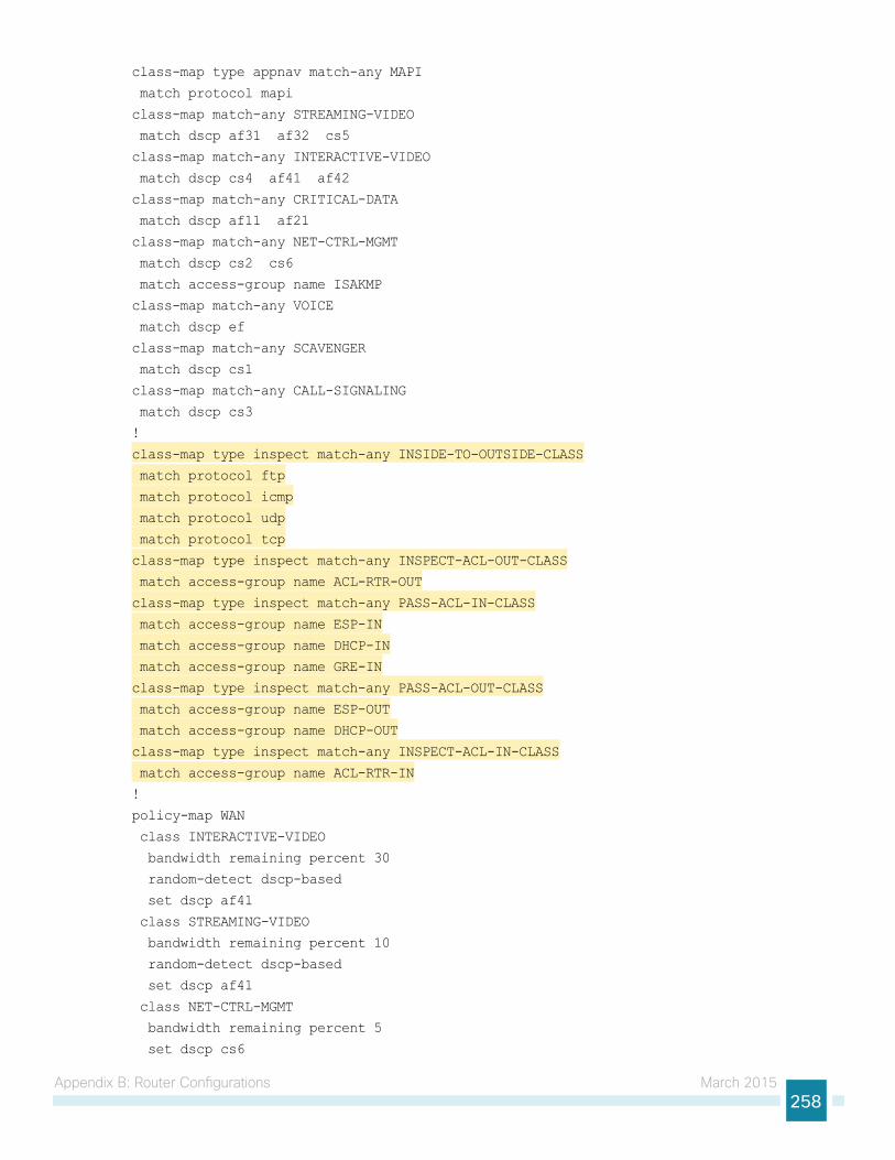
Appendix B: Router Configurations March 2015258
class-map type appnav match-any MAPI
match protocol mapi
class-map match-any STREAMING-VIDEO
match dscp af31 af32 cs5
class-map match-any INTERACTIVE-VIDEO
match dscp cs4 af41 af42
class-map match-any CRITICAL-DATA
match dscp af11 af21
class-map match-any NET-CTRL-MGMT
match dscp cs2 cs6
match access-group name ISAKMP
class-map match-any VOICE
match dscp ef
class-map match-any SCAVENGER
match dscp cs1
class-map match-any CALL-SIGNALING
match dscp cs3
!
class-map type inspect match-any INSIDE-TO-OUTSIDE-CLASS
match protocol ftp
match protocol icmp
match protocol udp
match protocol tcp
class-map type inspect match-any INSPECT-ACL-OUT-CLASS
match access-group name ACL-RTR-OUT
class-map type inspect match-any PASS-ACL-IN-CLASS
match access-group name ESP-IN
match access-group name DHCP-IN
match access-group name GRE-IN
class-map type inspect match-any PASS-ACL-OUT-CLASS
match access-group name ESP-OUT
match access-group name DHCP-OUT
class-map type inspect match-any INSPECT-ACL-IN-CLASS
match access-group name ACL-RTR-IN
!
policy-map WAN
class INTERACTIVE-VIDEO
bandwidth remaining percent 30
random-detect dscp-based
set dscp af41
class STREAMING-VIDEO
bandwidth remaining percent 10
random-detect dscp-based
set dscp af41
class NET-CTRL-MGMT
bandwidth remaining percent 5
set dscp cs6
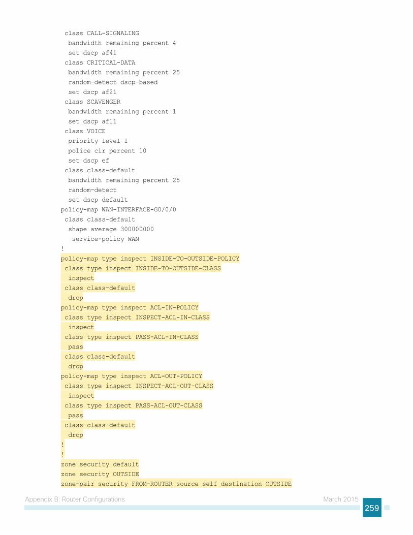
Appendix B: Router Configurations March 2015259
class CALL-SIGNALING
bandwidth remaining percent 4
set dscp af41
class CRITICAL-DATA
bandwidth remaining percent 25
random-detect dscp-based
set dscp af21
class SCAVENGER
bandwidth remaining percent 1
set dscp af11
class VOICE
priority level 1
police cir percent 10
set dscp ef
class class-default
bandwidth remaining percent 25
random-detect
set dscp default
policy-map WAN-INTERFACE-G0/0/0
class class-default
shape average 300000000
service-policy WAN
!
policy-map type inspect INSIDE-TO-OUTSIDE-POLICY
class type inspect INSIDE-TO-OUTSIDE-CLASS
inspect
class class-default
drop
policy-map type inspect ACL-IN-POLICY
class type inspect INSPECT-ACL-IN-CLASS
inspect
class type inspect PASS-ACL-IN-CLASS
pass
class class-default
drop
policy-map type inspect ACL-OUT-POLICY
class type inspect INSPECT-ACL-OUT-CLASS
inspect
class type inspect PASS-ACL-OUT-CLASS
pass
class class-default
drop
!
!
zone security default
zone security OUTSIDE
zone-pair security FROM-ROUTER source self destination OUTSIDE
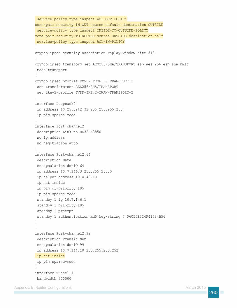
Appendix B: Router Configurations March 2015260
service-policy type inspect ACL-OUT-POLICY
zone-pair security IN_OUT source default destination OUTSIDE
service-policy type inspect INSIDE-TO-OUTSIDE-POLICY
zone-pair security TO-ROUTER source OUTSIDE destination self
service-policy type inspect ACL-IN-POLICY
!
crypto ipsec security-association replay window-size 512
!
crypto ipsec transform-set AES256/SHA/TRANSPORT esp-aes 256 esp-sha-hmac
mode transport
!
crypto ipsec profile DMVPN-PROFILE-TRANSPORT-2
set transform-set AES256/SHA/TRANSPORT
set ikev2-profile FVRF-IKEv2-IWAN-TRANSPORT-2
!
interface Loopback0
ip address 10.255.242.32 255.255.255.255
ip pim sparse-mode
!
interface Port-channel2
description Link to RS32-A3850
no ip address
no negotiation auto
!
interface Port-channel2.64
description Data
encapsulation dot1Q 64
ip address 10.7.146.3 255.255.255.0
ip helper-address 10.4.48.10
ip nat inside
ip pim dr-priority 105
ip pim sparse-mode
standby 1 ip 10.7.146.1
standby 1 priority 105
standby 1 preempt
standby 1 authentication md5 key-string 7 06055E324F41584B56
!
!
interface Port-channel2.99
description Transit Net
encapsulation dot1Q 99
ip address 10.7.144.10 255.255.255.252
ip nat inside
ip pim sparse-mode
!
interface Tunnel11
bandwidth 300000
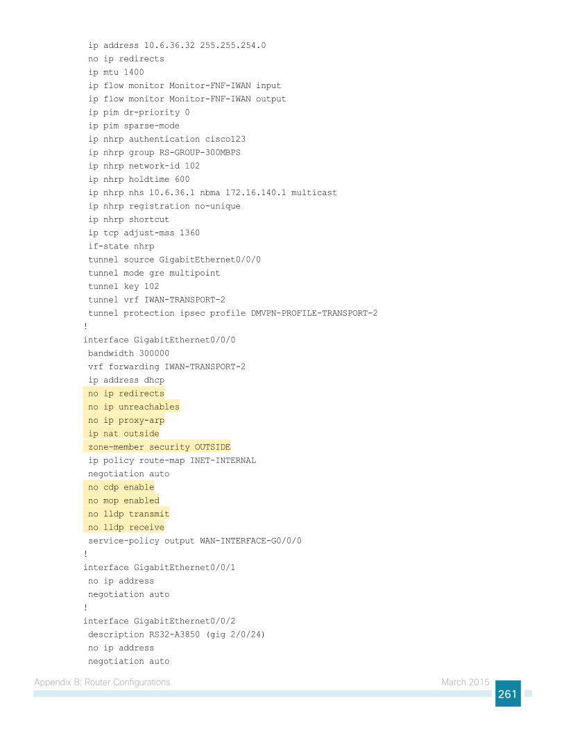
Appendix B: Router Configurations March 2015261
ip address 10.6.36.32 255.255.254.0
no ip redirects
ip mtu 1400
ip flow monitor Monitor-FNF-IWAN input
ip flow monitor Monitor-FNF-IWAN output
ip pim dr-priority 0
ip pim sparse-mode
ip nhrp authentication cisco123
ip nhrp group RS-GROUP-300MBPS
ip nhrp network-id 102
ip nhrp holdtime 600
ip nhrp nhs 10.6.36.1 nbma 172.16.140.1 multicast
ip nhrp registration no-unique
ip nhrp shortcut
ip tcp adjust-mss 1360
if-state nhrp
tunnel source GigabitEthernet0/0/0
tunnel mode gre multipoint
tunnel key 102
tunnel vrf IWAN-TRANSPORT-2
tunnel protection ipsec profile DMVPN-PROFILE-TRANSPORT-2
!
interface GigabitEthernet0/0/0
bandwidth 300000
vrf forwarding IWAN-TRANSPORT-2
ip address dhcp
no ip redirects
no ip unreachables
no ip proxy-arp
ip nat outside
zone-member security OUTSIDE
ip policy route-map INET-INTERNAL
negotiation auto
no cdp enable
no mop enabled
no lldp transmit
no lldp receive
service-policy output WAN-INTERFACE-G0/0/0
!
interface GigabitEthernet0/0/1
no ip address
negotiation auto
!
interface GigabitEthernet0/0/2
description RS32-A3850 (gig 2/0/24)
no ip address
negotiation auto
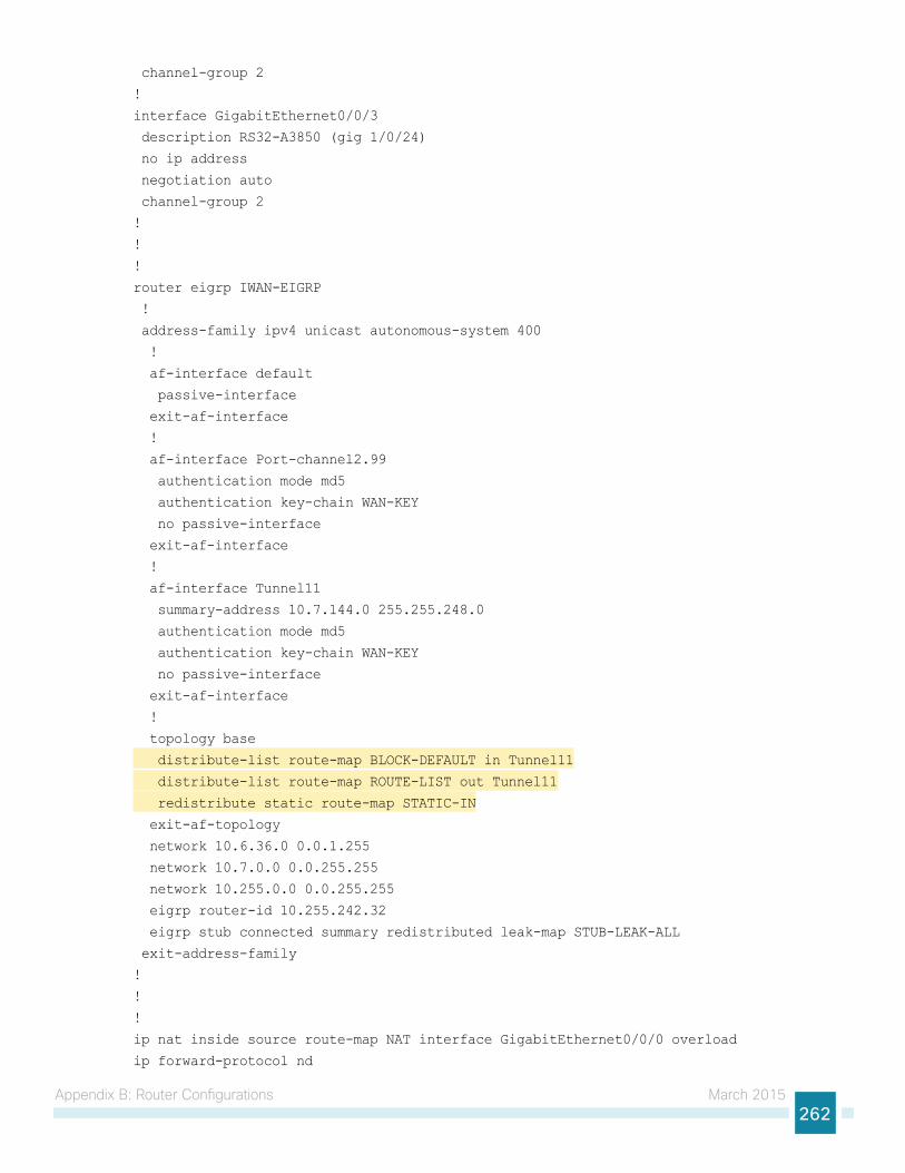
Appendix B: Router Configurations March 2015262
channel-group 2
!
interface GigabitEthernet0/0/3
description RS32-A3850 (gig 1/0/24)
no ip address
negotiation auto
channel-group 2
!
!
!
router eigrp IWAN-EIGRP
!
address-family ipv4 unicast autonomous-system 400
!
af-interface default
passive-interface
exit-af-interface
!
af-interface Port-channel2.99
authentication mode md5
authentication key-chain WAN-KEY
no passive-interface
exit-af-interface
!
af-interface Tunnel11
summary-address 10.7.144.0 255.255.248.0
authentication mode md5
authentication key-chain WAN-KEY
no passive-interface
exit-af-interface
!
topology base
distribute-list route-map BLOCK-DEFAULT in Tunnel11
distribute-list route-map ROUTE-LIST out Tunnel11
redistribute static route-map STATIC-IN
exit-af-topology
network 10.6.36.0 0.0.1.255
network 10.7.0.0 0.0.255.255
network 10.255.0.0 0.0.255.255
eigrp router-id 10.255.242.32
eigrp stub connected summary redistributed leak-map STUB-LEAK-ALL
exit-address-family
!
!
!
ip nat inside source route-map NAT interface GigabitEthernet0/0/0 overload
ip forward-protocol nd

Appendix B: Router Configurations March 2015263
no ip http server
ip http authentication aaa
ip http secure-server
ip http secure-trustpoint TP-self-signed-98238700
ip http client secure-trustpoint TP-self-signed-98238700
ip pim autorp listener
ip pim register-source Loopback0
ip route 10.0.0.0 255.0.0.0 Null0 254
ip route 0.0.0.0 0.0.0.0 GigabitEthernet0/0/0 dhcp 10
!
!
ip access-list standard ALL-EXCEPT-DEFAULT
deny 0.0.0.0
permit any
ip access-list standard DEFAULT-ONLY
permit 0.0.0.0
ip access-list standard STATIC-ROUTE-LIST
permit 10.7.146.9
!
ip access-list extended ACL-RTR-IN
permit udp any any eq non500-isakmp
permit udp any any eq isakmp
permit icmp any any echo
permit icmp any any echo-reply
permit icmp any any ttl-exceeded
permit icmp any any port-unreachable
permit udp any any gt 1023 ttl eq 1
ip access-list extended ACL-RTR-OUT
permit udp any any eq non500-isakmp
permit udp any any eq isakmp
permit icmp any any
ip access-list extended DHCP-IN
permit udp any eq bootps any eq bootpc
ip access-list extended DHCP-OUT
permit udp any eq bootpc any eq bootps
ip access-list extended ESP-IN
permit esp any any
ip access-list extended ESP-OUT
permit esp any any
ip access-list extended GRE-IN
permit gre any any
!
ip access-list extended ISAKMP
permit udp any eq isakmp any eq isakmp
ip access-list extended NAT-LOCAL
permit ip 10.7.144.0 0.0.7.255 any
!
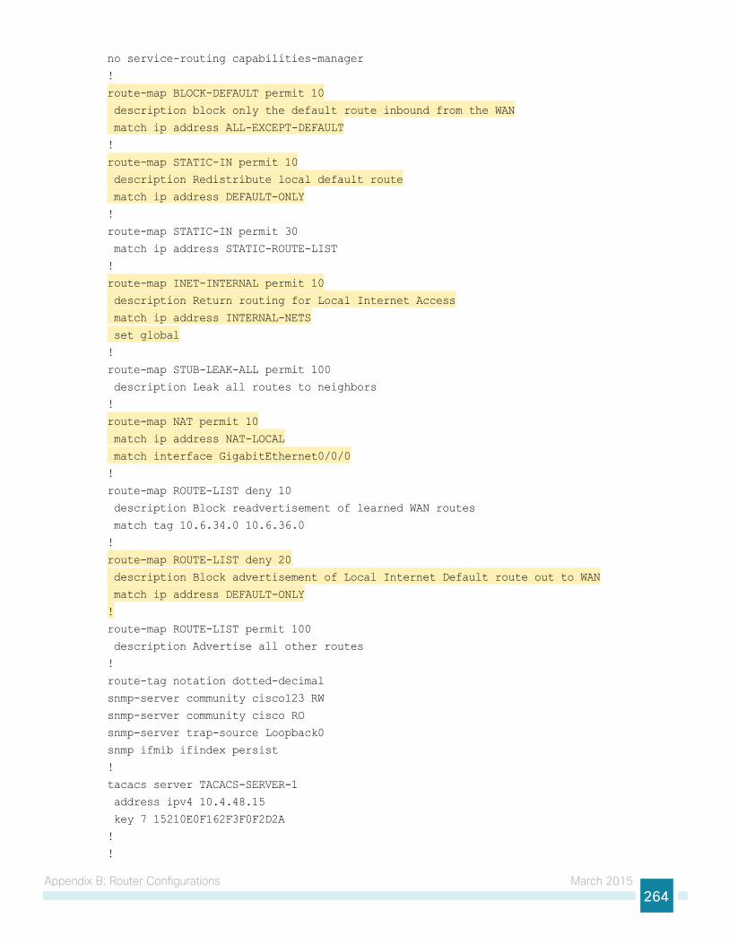
Appendix B: Router Configurations March 2015264
no service-routing capabilities-manager
!
route-map BLOCK-DEFAULT permit 10
description block only the default route inbound from the WAN
match ip address ALL-EXCEPT-DEFAULT
!
route-map STATIC-IN permit 10
description Redistribute local default route
match ip address DEFAULT-ONLY
!
route-map STATIC-IN permit 30
match ip address STATIC-ROUTE-LIST
!
route-map INET-INTERNAL permit 10
description Return routing for Local Internet Access
match ip address INTERNAL-NETS
set global
!
route-map STUB-LEAK-ALL permit 100
description Leak all routes to neighbors
!
route-map NAT permit 10
match ip address NAT-LOCAL
match interface GigabitEthernet0/0/0
!
route-map ROUTE-LIST deny 10
description Block readvertisement of learned WAN routes
match tag 10.6.34.0 10.6.36.0
!
route-map ROUTE-LIST deny 20
description Block advertisement of Local Internet Default route out to WAN
match ip address DEFAULT-ONLY
!
route-map ROUTE-LIST permit 100
description Advertise all other routes
!
route-tag notation dotted-decimal
snmp-server community cisco123 RW
snmp-server community cisco RO
snmp-server trap-source Loopback0
snmp ifmib ifindex persist
!
tacacs server TACACS-SERVER-1
address ipv4 10.4.48.15
key 7 15210E0F162F3F0F2D2A
!
!
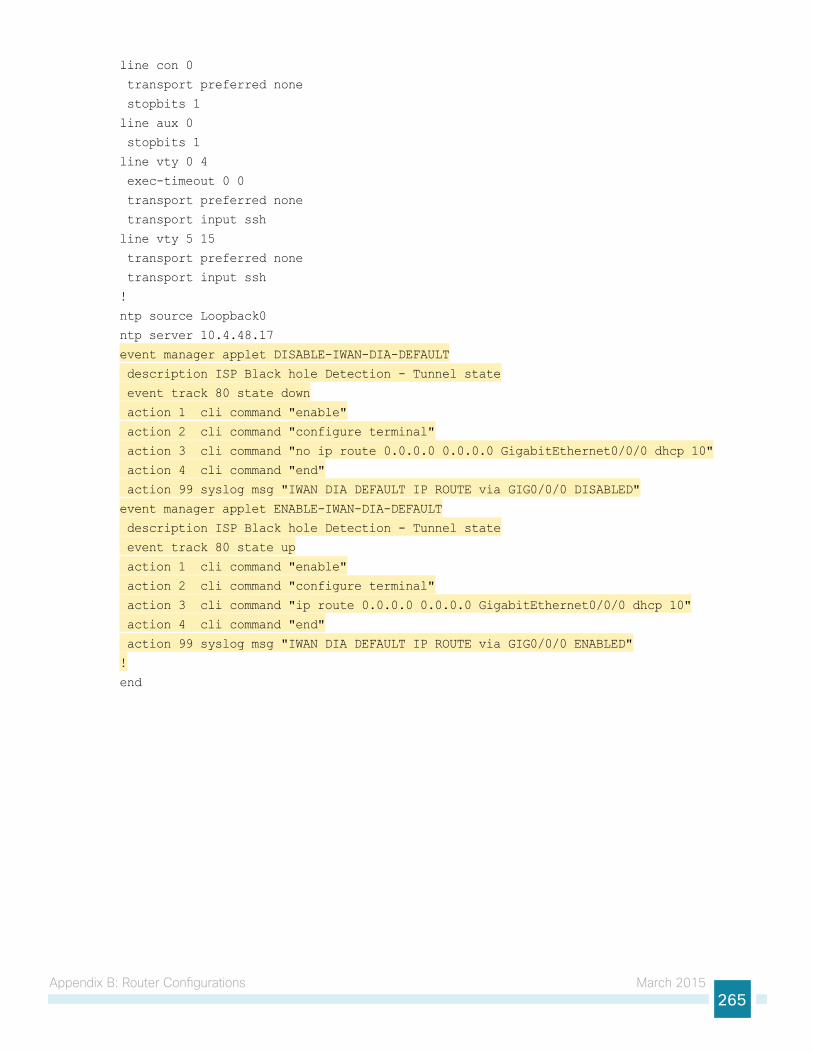
Appendix B: Router Configurations March 2015265
line con 0
transport preferred none
stopbits 1
line aux 0
stopbits 1
line vty 0 4
exec-timeout 0 0
transport preferred none
transport input ssh
line vty 5 15
transport preferred none
transport input ssh
!
ntp source Loopback0
ntp server 10.4.48.17
event manager applet DISABLE-IWAN-DIA-DEFAULT
description ISP Black hole Detection - Tunnel state
event track 80 state down
action 1 cli command "enable"
action 2 cli command "configure terminal"
action 3 cli command "no ip route 0.0.0.0 0.0.0.0 GigabitEthernet0/0/0 dhcp 10"
action 4 cli command "end"
action 99 syslog msg "IWAN DIA DEFAULT IP ROUTE via GIG0/0/0 DISABLED"
event manager applet ENABLE-IWAN-DIA-DEFAULT
description ISP Black hole Detection - Tunnel state
event track 80 state up
action 1 cli command "enable"
action 2 cli command "configure terminal"
action 3 cli command "ip route 0.0.0.0 0.0.0.0 GigabitEthernet0/0/0 dhcp 10"
action 4 cli command "end"
action 99 syslog msg "IWAN DIA DEFAULT IP ROUTE via GIG0/0/0 ENABLED"
!
end
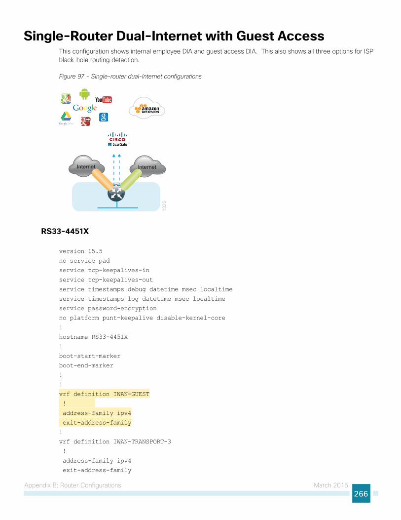
Appendix B: Router Configurations March 2015266
Single-Router Dual-Internet with Guest AccessThis configuration shows internal employee DIA and guest access DIA. This also shows all three options for ISP black-hole routing detection.
Figure 97 - Single-router dual-Internet configurations
13
25
Internet Internet
RS33-4451X
version 15.5
no service pad
service tcp-keepalives-in
service tcp-keepalives-out
service timestamps debug datetime msec localtime
service timestamps log datetime msec localtime
service password-encryption
no platform punt-keepalive disable-kernel-core
!
hostname RS33-4451X
!
boot-start-marker
boot-end-marker
!
!
vrf definition IWAN-GUEST
!
address-family ipv4
exit-address-family
!
vrf definition IWAN-TRANSPORT-3
!
address-family ipv4
exit-address-family
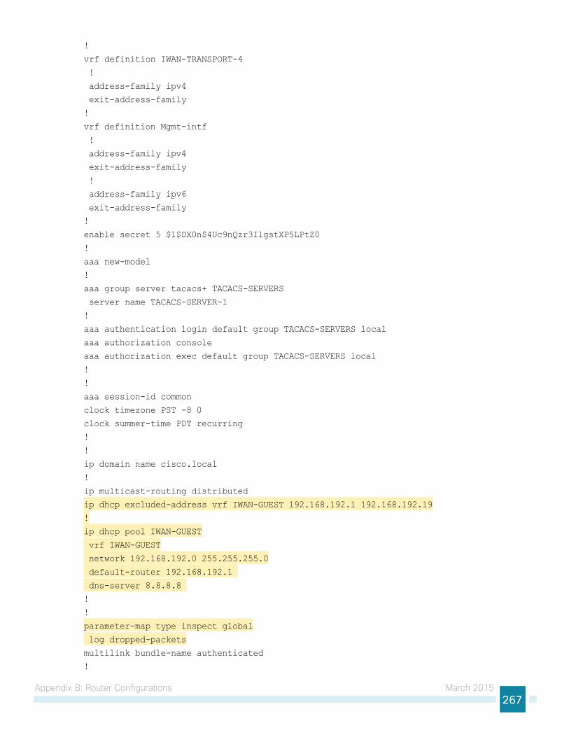
Appendix B: Router Configurations March 2015267
!
vrf definition IWAN-TRANSPORT-4
!
address-family ipv4
exit-address-family
!
vrf definition Mgmt-intf
!
address-family ipv4
exit-address-family
!
address-family ipv6
exit-address-family
!
enable secret 5 $1$DX0n$4Uc9nQzr3IlgstXP5LPtZ0
!
aaa new-model
!
aaa group server tacacs+ TACACS-SERVERS
server name TACACS-SERVER-1
!
aaa authentication login default group TACACS-SERVERS local
aaa authorization console
aaa authorization exec default group TACACS-SERVERS local
!
!
aaa session-id common
clock timezone PST -8 0
clock summer-time PDT recurring
!
!
ip domain name cisco.local
!
ip multicast-routing distributed
ip dhcp excluded-address vrf IWAN-GUEST 192.168.192.1 192.168.192.19
!
ip dhcp pool IWAN-GUEST
vrf IWAN-GUEST
network 192.168.192.0 255.255.255.0
default-router 192.168.192.1
dns-server 8.8.8.8
!
!
parameter-map type inspect global
log dropped-packets
multilink bundle-name authenticated
!
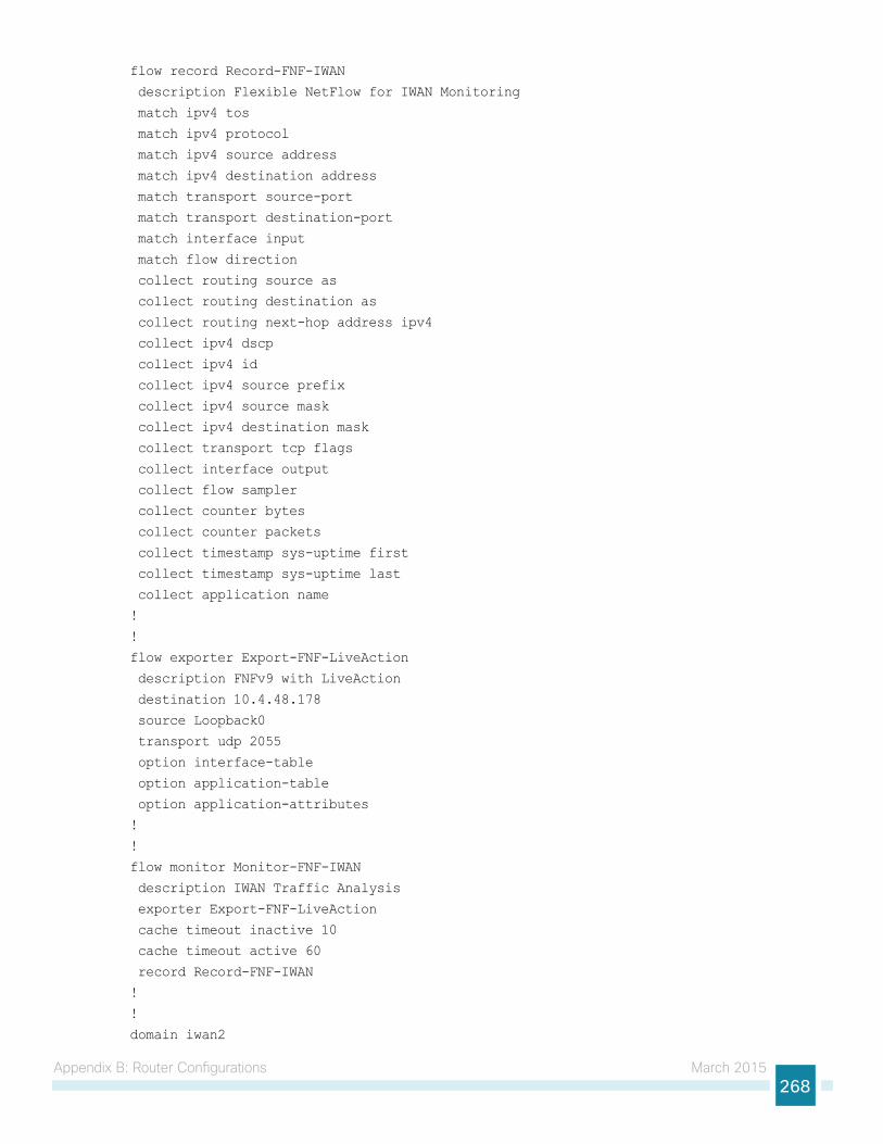
Appendix B: Router Configurations March 2015268
flow record Record-FNF-IWAN
description Flexible NetFlow for IWAN Monitoring
match ipv4 tos
match ipv4 protocol
match ipv4 source address
match ipv4 destination address
match transport source-port
match transport destination-port
match interface input
match flow direction
collect routing source as
collect routing destination as
collect routing next-hop address ipv4
collect ipv4 dscp
collect ipv4 id
collect ipv4 source prefix
collect ipv4 source mask
collect ipv4 destination mask
collect transport tcp flags
collect interface output
collect flow sampler
collect counter bytes
collect counter packets
collect timestamp sys-uptime first
collect timestamp sys-uptime last
collect application name
!
!
flow exporter Export-FNF-LiveAction
description FNFv9 with LiveAction
destination 10.4.48.178
source Loopback0
transport udp 2055
option interface-table
option application-table
option application-attributes
!
!
flow monitor Monitor-FNF-IWAN
description IWAN Traffic Analysis
exporter Export-FNF-LiveAction
cache timeout inactive 10
cache timeout active 60
record Record-FNF-IWAN
!
!
domain iwan2
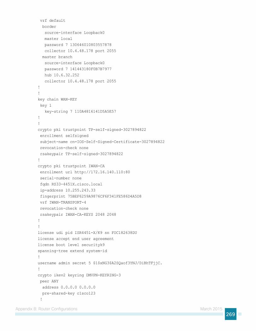
Appendix B: Router Configurations March 2015269
vrf default
border
source-interface Loopback0
master local
password 7 130646010803557878
collector 10.4.48.178 port 2055
master branch
source-interface Loopback0
password 7 141443180F0B7B7977
hub 10.6.32.252
collector 10.4.48.178 port 2055
!
!
key chain WAN-KEY
key 1
key-string 7 110A4816141D5A5E57
!
!
crypto pki trustpoint TP-self-signed-3027894822
enrollment selfsigned
subject-name cn=IOS-Self-Signed-Certificate-3027894822
revocation-check none
rsakeypair TP-self-signed-3027894822
!
crypto pki trustpoint IWAN-CA
enrollment url http://172.16.140.110:80
serial-number none
fqdn RS33-4451X.cisco.local
ip-address 10.255.243.33
fingerprint 75BEF6259A9876CF6F341FE586D4A5D8
vrf IWAN-TRANSPORT-4
revocation-check none
rsakeypair IWAN-CA-KEYS 2048 2048
!
!
license udi pid ISR4451-X/K9 sn FOC182638DU
license accept end user agreement
license boot level securityk9
spanning-tree extend system-id
!
username admin secret 5 $1$xNG3$A2SQaof3YNJ/DiBhTFjjC.
!
crypto ikev2 keyring DMVPN-KEYRING-3
peer ANY
address 0.0.0.0 0.0.0.0
pre-shared-key c1sco123
!
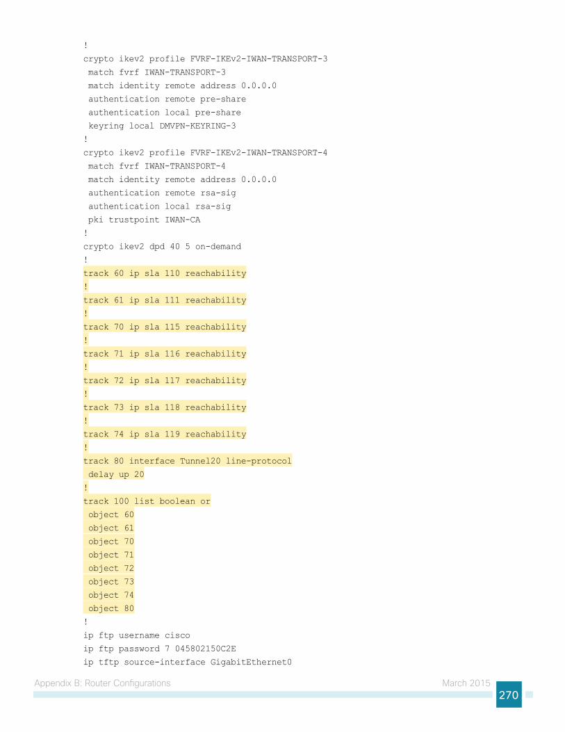
Appendix B: Router Configurations March 2015270
!
crypto ikev2 profile FVRF-IKEv2-IWAN-TRANSPORT-3
match fvrf IWAN-TRANSPORT-3
match identity remote address 0.0.0.0
authentication remote pre-share
authentication local pre-share
keyring local DMVPN-KEYRING-3
!
crypto ikev2 profile FVRF-IKEv2-IWAN-TRANSPORT-4
match fvrf IWAN-TRANSPORT-4
match identity remote address 0.0.0.0
authentication remote rsa-sig
authentication local rsa-sig
pki trustpoint IWAN-CA
!
crypto ikev2 dpd 40 5 on-demand
!
track 60 ip sla 110 reachability
!
track 61 ip sla 111 reachability
!
track 70 ip sla 115 reachability
!
track 71 ip sla 116 reachability
!
track 72 ip sla 117 reachability
!
track 73 ip sla 118 reachability
!
track 74 ip sla 119 reachability
!
track 80 interface Tunnel20 line-protocol
delay up 20
!
track 100 list boolean or
object 60
object 61
object 70
object 71
object 72
object 73
object 74
object 80
!
ip ftp username cisco
ip ftp password 7 045802150C2E
ip tftp source-interface GigabitEthernet0
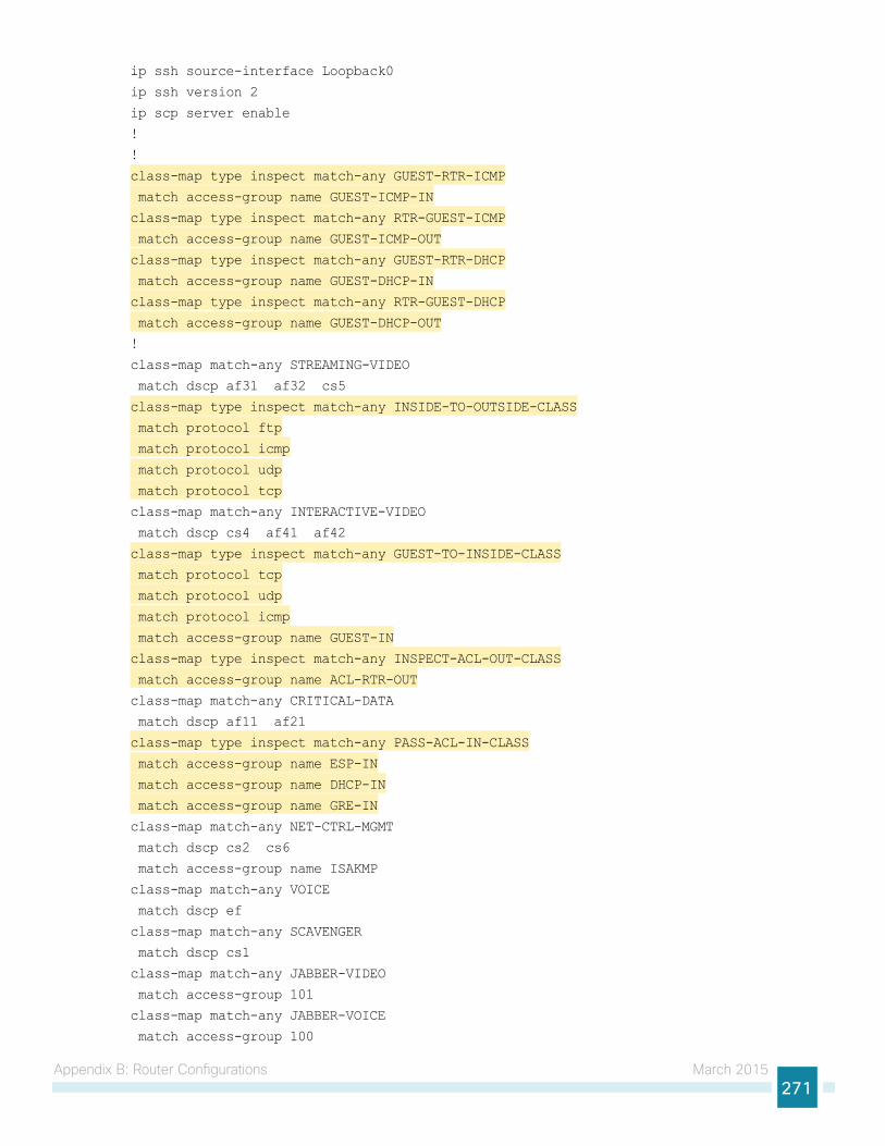
Appendix B: Router Configurations March 2015271
ip ssh source-interface Loopback0
ip ssh version 2
ip scp server enable
!
!
class-map type inspect match-any GUEST-RTR-ICMP
match access-group name GUEST-ICMP-IN
class-map type inspect match-any RTR-GUEST-ICMP
match access-group name GUEST-ICMP-OUT
class-map type inspect match-any GUEST-RTR-DHCP
match access-group name GUEST-DHCP-IN
class-map type inspect match-any RTR-GUEST-DHCP
match access-group name GUEST-DHCP-OUT
!
class-map match-any STREAMING-VIDEO
match dscp af31 af32 cs5
class-map type inspect match-any INSIDE-TO-OUTSIDE-CLASS
match protocol ftp
match protocol icmp
match protocol udp
match protocol tcp
class-map match-any INTERACTIVE-VIDEO
match dscp cs4 af41 af42
class-map type inspect match-any GUEST-TO-INSIDE-CLASS
match protocol tcp
match protocol udp
match protocol icmp
match access-group name GUEST-IN
class-map type inspect match-any INSPECT-ACL-OUT-CLASS
match access-group name ACL-RTR-OUT
class-map match-any CRITICAL-DATA
match dscp af11 af21
class-map type inspect match-any PASS-ACL-IN-CLASS
match access-group name ESP-IN
match access-group name DHCP-IN
match access-group name GRE-IN
class-map match-any NET-CTRL-MGMT
match dscp cs2 cs6
match access-group name ISAKMP
class-map match-any VOICE
match dscp ef
class-map match-any SCAVENGER
match dscp cs1
class-map match-any JABBER-VIDEO
match access-group 101
class-map match-any JABBER-VOICE
match access-group 100
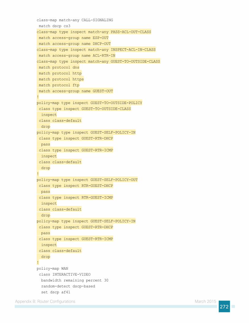
Appendix B: Router Configurations March 2015272
class-map match-any CALL-SIGNALING
match dscp cs3
class-map type inspect match-any PASS-ACL-OUT-CLASS
match access-group name ESP-OUT
match access-group name DHCP-OUT
class-map type inspect match-any INSPECT-ACL-IN-CLASS
match access-group name ACL-RTR-IN
class-map type inspect match-any GUEST-TO-OUTSIDE-CLASS
match protocol dns
match protocol http
match protocol https
match protocol ftp
match access-group name GUEST-OUT
!
policy-map type inspect GUEST-TO-OUTSIDE-POLICY
class type inspect GUEST-TO-OUTSIDE-CLASS
inspect
class class-default
drop
policy-map type inspect GUEST-SELF-POLICY-IN
class type inspect GUEST-RTR-DHCP
pass
class type inspect GUEST-RTR-ICMP
inspect
class class-default
drop
!
policy-map type inspect GUEST-SELF-POLICY-OUT
class type inspect RTR-GUEST-DHCP
pass
class type inspect RTR-GUEST-ICMP
inspect
class class-default
drop
policy-map type inspect GUEST-SELF-POLICY-IN
class type inspect GUEST-RTR-DHCP
pass
class type inspect GUEST-RTR-ICMP
inspect
class class-default
drop
!
policy-map WAN
class INTERACTIVE-VIDEO
bandwidth remaining percent 30
random-detect dscp-based
set dscp af41
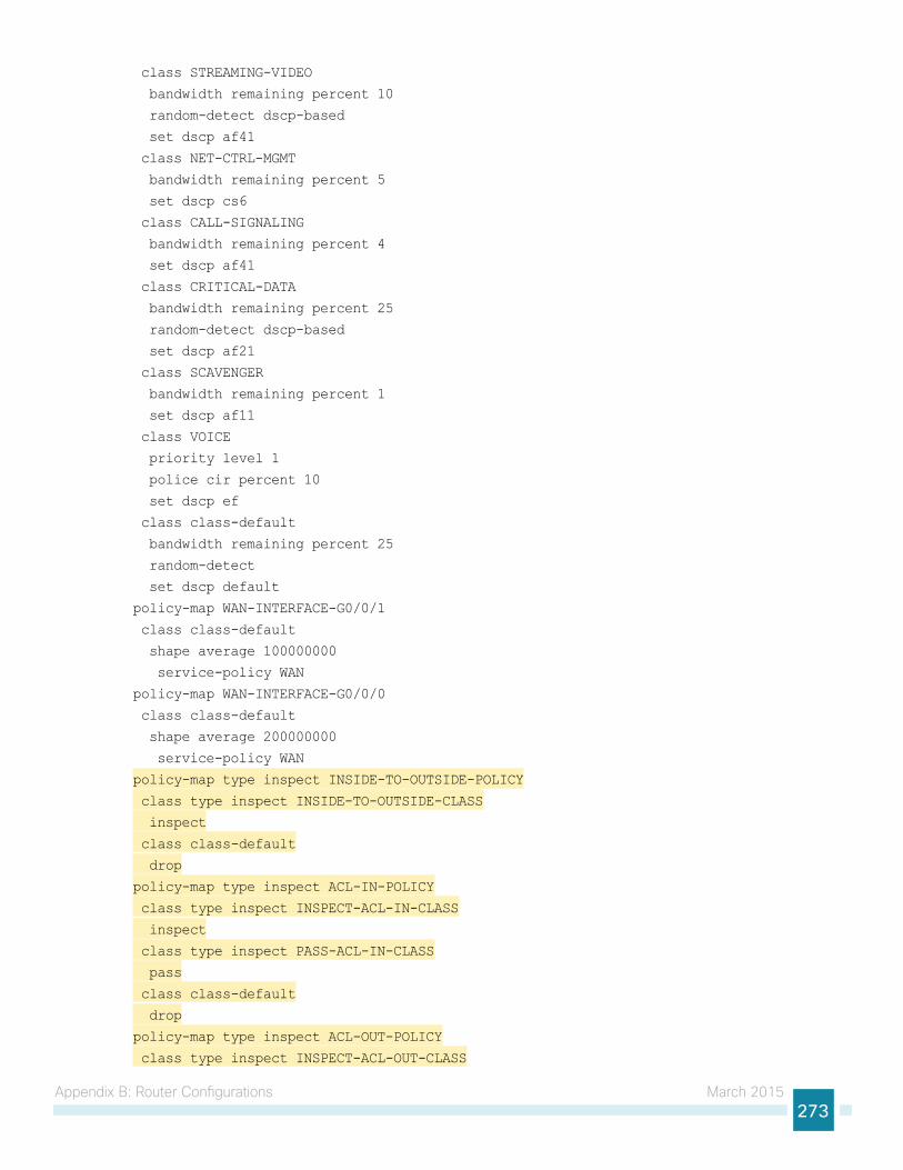
Appendix B: Router Configurations March 2015273
class STREAMING-VIDEO
bandwidth remaining percent 10
random-detect dscp-based
set dscp af41
class NET-CTRL-MGMT
bandwidth remaining percent 5
set dscp cs6
class CALL-SIGNALING
bandwidth remaining percent 4
set dscp af41
class CRITICAL-DATA
bandwidth remaining percent 25
random-detect dscp-based
set dscp af21
class SCAVENGER
bandwidth remaining percent 1
set dscp af11
class VOICE
priority level 1
police cir percent 10
set dscp ef
class class-default
bandwidth remaining percent 25
random-detect
set dscp default
policy-map WAN-INTERFACE-G0/0/1
class class-default
shape average 100000000
service-policy WAN
policy-map WAN-INTERFACE-G0/0/0
class class-default
shape average 200000000
service-policy WAN
policy-map type inspect INSIDE-TO-OUTSIDE-POLICY
class type inspect INSIDE-TO-OUTSIDE-CLASS
inspect
class class-default
drop
policy-map type inspect ACL-IN-POLICY
class type inspect INSPECT-ACL-IN-CLASS
inspect
class type inspect PASS-ACL-IN-CLASS
pass
class class-default
drop
policy-map type inspect ACL-OUT-POLICY
class type inspect INSPECT-ACL-OUT-CLASS

Appendix B: Router Configurations March 2015274
inspect
class type inspect PASS-ACL-OUT-CLASS
pass
class class-default
drop
policy-map type inspect GUEST-TO-INSIDE-POLICY
class type inspect GUEST-TO-INSIDE-CLASS
inspect
class class-default
drop
!
zone security OUTSIDE-A
zone security OUTSIDE-B
zone security GUEST
zone security default
!
zone-pair security FROM-ROUTER-A source self destination OUTSIDE-A
service-policy type inspect ACL-OUT-POLICY
zone-pair security FROM-ROUTER-B source self destination OUTSIDE-B
service-policy type inspect ACL-OUT-POLICY
zone-pair security GUEST-IN source GUEST destination default
service-policy type inspect GUEST-TO-INSIDE-POLICY
zone-pair security GUEST-OUT-A source GUEST destination OUTSIDE-A
service-policy type inspect GUEST-TO-OUTSIDE-POLICY
zone-pair security GUEST-OUT-B source GUEST destination OUTSIDE-B
zone-pair security IN_OUT-A source default destination OUTSIDE-A
service-policy type inspect INSIDE-TO-OUTSIDE-POLICY
zone-pair security IN_OUT-B source default destination OUTSIDE-B
service-policy type inspect INSIDE-TO-OUTSIDE-POLICY
zone-pair security TO-ROUTER-A source OUTSIDE-A destination self
service-policy type inspect ACL-IN-POLICY
zone-pair security TO-ROUTER-B source OUTSIDE-B destination self
service-policy type inspect ACL-IN-POLICY
zone-pair security GUEST-RTR-IN source GUEST destination self
service-policy type inspect GUEST-SELF-POLICY-IN
zone-pair security RTR-GUEST-OUT source self destination GUEST
service-policy type inspect GUEST-SELF-POLICY-OUT
!
crypto ipsec security-association replay window-size 512
!
crypto ipsec transform-set AES256/SHA/TRANSPORT esp-aes 256 esp-sha-hmac
mode transport
!
crypto ipsec profile DMVPN-PROFILE-TRANSPORT-3
set transform-set AES256/SHA/TRANSPORT
set ikev2-profile FVRF-IKEv2-IWAN-TRANSPORT-3
!
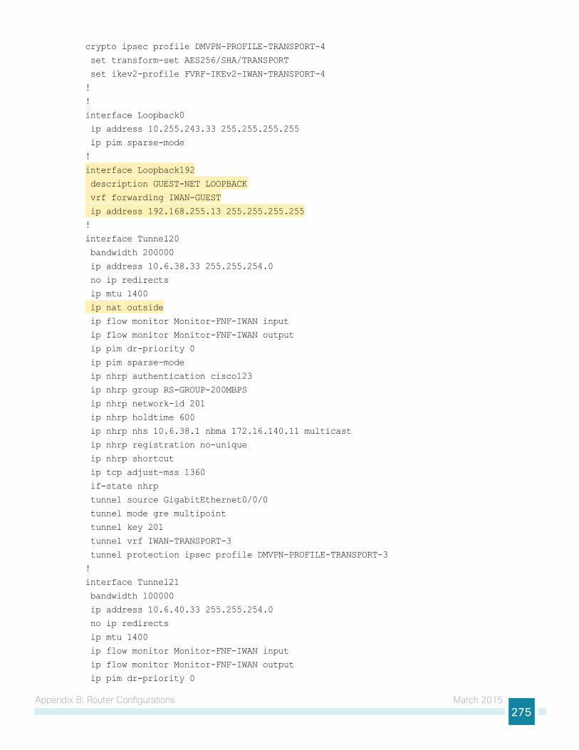
Appendix B: Router Configurations March 2015275
crypto ipsec profile DMVPN-PROFILE-TRANSPORT-4
set transform-set AES256/SHA/TRANSPORT
set ikev2-profile FVRF-IKEv2-IWAN-TRANSPORT-4
!
!
interface Loopback0
ip address 10.255.243.33 255.255.255.255
ip pim sparse-mode
!
interface Loopback192
description GUEST-NET LOOPBACK
vrf forwarding IWAN-GUEST
ip address 192.168.255.13 255.255.255.255
!
interface Tunnel20
bandwidth 200000
ip address 10.6.38.33 255.255.254.0
no ip redirects
ip mtu 1400
ip nat outside
ip flow monitor Monitor-FNF-IWAN input
ip flow monitor Monitor-FNF-IWAN output
ip pim dr-priority 0
ip pim sparse-mode
ip nhrp authentication cisco123
ip nhrp group RS-GROUP-200MBPS
ip nhrp network-id 201
ip nhrp holdtime 600
ip nhrp nhs 10.6.38.1 nbma 172.16.140.11 multicast
ip nhrp registration no-unique
ip nhrp shortcut
ip tcp adjust-mss 1360
if-state nhrp
tunnel source GigabitEthernet0/0/0
tunnel mode gre multipoint
tunnel key 201
tunnel vrf IWAN-TRANSPORT-3
tunnel protection ipsec profile DMVPN-PROFILE-TRANSPORT-3
!
interface Tunnel21
bandwidth 100000
ip address 10.6.40.33 255.255.254.0
no ip redirects
ip mtu 1400
ip flow monitor Monitor-FNF-IWAN input
ip flow monitor Monitor-FNF-IWAN output
ip pim dr-priority 0
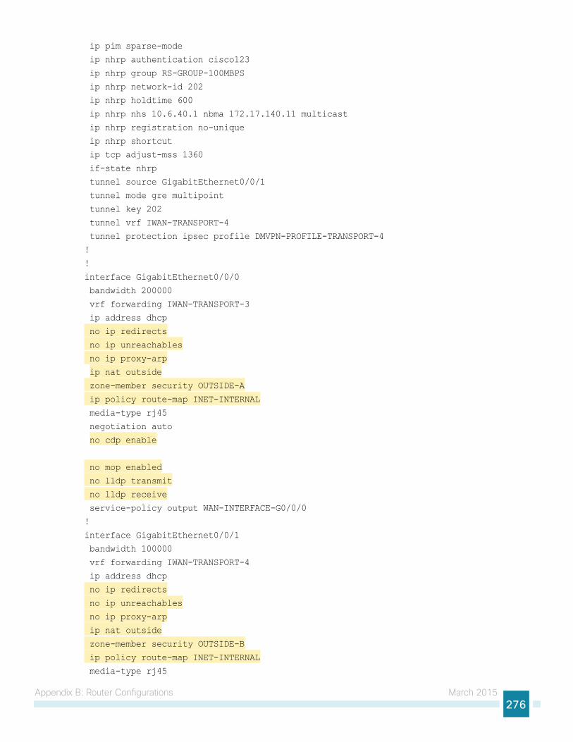
Appendix B: Router Configurations March 2015276
ip pim sparse-mode
ip nhrp authentication cisco123
ip nhrp group RS-GROUP-100MBPS
ip nhrp network-id 202
ip nhrp holdtime 600
ip nhrp nhs 10.6.40.1 nbma 172.17.140.11 multicast
ip nhrp registration no-unique
ip nhrp shortcut
ip tcp adjust-mss 1360
if-state nhrp
tunnel source GigabitEthernet0/0/1
tunnel mode gre multipoint
tunnel key 202
tunnel vrf IWAN-TRANSPORT-4
tunnel protection ipsec profile DMVPN-PROFILE-TRANSPORT-4
!
!
interface GigabitEthernet0/0/0
bandwidth 200000
vrf forwarding IWAN-TRANSPORT-3
ip address dhcp
no ip redirects
no ip unreachables
no ip proxy-arp
ip nat outside
zone-member security OUTSIDE-A
ip policy route-map INET-INTERNAL
media-type rj45
negotiation auto
no cdp enable
no mop enabled
no lldp transmit
no lldp receive
service-policy output WAN-INTERFACE-G0/0/0
!
interface GigabitEthernet0/0/1
bandwidth 100000
vrf forwarding IWAN-TRANSPORT-4
ip address dhcp
no ip redirects
no ip unreachables
no ip proxy-arp
ip nat outside
zone-member security OUTSIDE-B
ip policy route-map INET-INTERNAL
media-type rj45
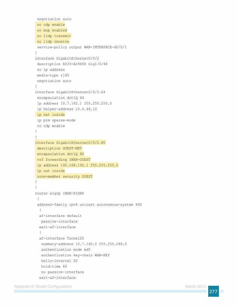
Appendix B: Router Configurations March 2015277
negotiation auto
no cdp enable
no mop enabled
no lldp transmit
no lldp receive
service-policy output WAN-INTERFACE-G0/0/1
!
interface GigabitEthernet0/0/2
description RS33-A2960X Gig1/0/48
no ip address
media-type rj45
negotiation auto
!
interface GigabitEthernet0/0/2.64
encapsulation dot1Q 64
ip address 10.7.162.1 255.255.255.0
ip helper-address 10.4.48.10
ip nat inside
ip pim sparse-mode
no cdp enable
!
!
interface GigabitEthernet0/0/2.80
description GUEST-NET
encapsulation dot1Q 80
vrf forwarding IWAN-GUEST
ip address 192.168.192.1 255.255.255.0
ip nat inside
zone-member security GUEST
!
!
router eigrp IWAN-EIGRP
!
address-family ipv4 unicast autonomous-system 400
!
af-interface default
passive-interface
exit-af-interface
!
af-interface Tunnel20
summary-address 10.7.160.0 255.255.248.0
authentication mode md5
authentication key-chain WAN-KEY
hello-interval 20
hold-time 60
no passive-interface
exit-af-interface
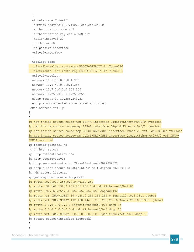
Appendix B: Router Configurations March 2015278
!
af-interface Tunnel21
summary-address 10.7.160.0 255.255.248.0
authentication mode md5
authentication key-chain WAN-KEY
hello-interval 20
hold-time 60
no passive-interface
exit-af-interface
!
topology base
distribute-list route-map BLOCK-DEFAULT in Tunnel20
distribute-list route-map BLOCK-DEFAULT in Tunnel21
exit-af-topology
network 10.6.38.0 0.0.1.255
network 10.6.40.0 0.0.1.255
network 10.7.0.0 0.0.255.255
network 10.255.0.0 0.0.255.255
eigrp router-id 10.255.243.33
eigrp stub connected summary redistributed
exit-address-family
!
!
ip nat inside source route-map ISP-A interface GigabitEthernet0/0/0 overload
ip nat inside source route-map ISP-B interface GigabitEthernet0/0/1 overload
ip nat inside source route-map GUEST-NAT-AUTH interface Tunnel20 vrf IWAN-GUEST overload
ip nat inside source route-map GUEST-NAT-INET interface GigabitEthernet0/0/0 vrf IWAN-
GUEST overload
ip forward-protocol nd
no ip http server
ip http authentication aaa
ip http secure-server
ip http secure-trustpoint TP-self-signed-3027894822
ip http client secure-trustpoint TP-self-signed-3027894822
ip pim autorp listener
ip pim register-source Loopback0
ip route 10.0.0.0 255.0.0.0 Null0 254
ip route 192.168.192.0 255.255.255.0 GigabitEthernet0/0/2.80
ip route 192.168.255.13 255.255.255.255 Loopback192
ip route vrf IWAN-GUEST 10.4.48.0 255.255.255.0 Tunnel20 10.6.38.1 global
ip route vrf IWAN-GUEST 192.168.144.0 255.255.255.0 Tunnel20 10.6.38.1 global
ip route 0.0.0.0 0.0.0.0 GigabitEthernet0/0/1 dhcp 15
ip route 0.0.0.0 0.0.0.0 GigabitEthernet0/0/0 dhcp 10
ip route vrf IWAN-GUEST 0.0.0.0 0.0.0.0 GigabitEthernet0/0/0 dhcp 10
ip tacacs source-interface Loopback0
!
!

Appendix B: Router Configurations March 2015279
ip access-list standard ALL-EXCEPT-DEFAULT
deny 0.0.0.0
permit any
!
ip access-list extended ACL-RTR-IN
permit udp any any eq non500-isakmp
permit udp any any eq isakmp
permit icmp any any echo
permit icmp any any echo-reply
permit icmp any any ttl-exceeded
permit icmp any any port-unreachable
permit udp any any gt 1023 ttl eq 1
!
ip access-list extended ACL-RTR-OUT
permit udp any any eq non500-isakmp
permit udp any any eq isakmp
permit icmp any any
permit tcp any any eq 8080
permit udp any any eq domain
!
ip access-list extended DHCP-IN
permit udp any eq bootps any eq bootpc
!
ip access-list extended DHCP-OUT
permit udp any eq bootpc any eq bootps
!
ip access-list extended ESP-IN
permit esp any any
!
ip access-list extended ESP-OUT
permit esp any any
!
ip access-list extended GRE-IN
permit gre any any
!
ip access-list extended GUEST-AUTH
permit ip 192.168.192.0 0.0.0.255 192.168.144.0 0.0.0.255
permit ip 192.168.192.0 0.0.0.255 10.4.48.0 0.0.0.255
!
ip access-list extended GUEST-DHCP-IN
permit udp any eq bootpc any eq bootps
!
ip access-list extended GUEST-DHCP-OUT
permit udp any eq bootps any eq bootpc
!
ip access-list extended GUEST-ICMP-IN
permit icmp any any echo
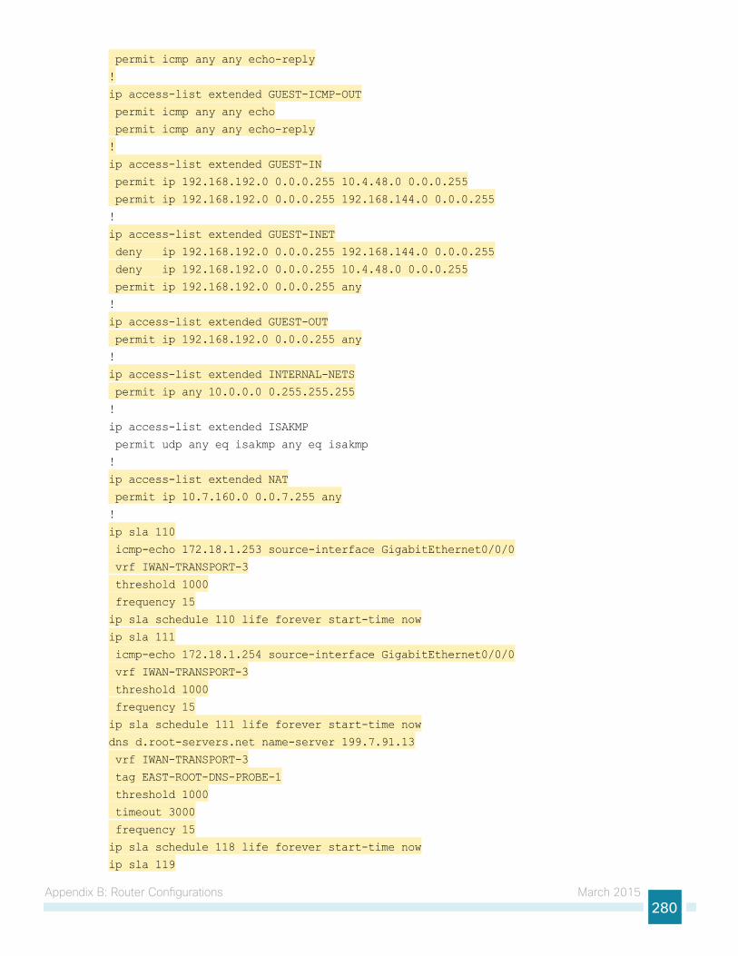
Appendix B: Router Configurations March 2015280
permit icmp any any echo-reply
!
ip access-list extended GUEST-ICMP-OUT
permit icmp any any echo
permit icmp any any echo-reply
!
ip access-list extended GUEST-IN
permit ip 192.168.192.0 0.0.0.255 10.4.48.0 0.0.0.255
permit ip 192.168.192.0 0.0.0.255 192.168.144.0 0.0.0.255
!
ip access-list extended GUEST-INET
deny ip 192.168.192.0 0.0.0.255 192.168.144.0 0.0.0.255
deny ip 192.168.192.0 0.0.0.255 10.4.48.0 0.0.0.255
permit ip 192.168.192.0 0.0.0.255 any
!
ip access-list extended GUEST-OUT
permit ip 192.168.192.0 0.0.0.255 any
!
ip access-list extended INTERNAL-NETS
permit ip any 10.0.0.0 0.255.255.255
!
ip access-list extended ISAKMP
permit udp any eq isakmp any eq isakmp
!
ip access-list extended NAT
permit ip 10.7.160.0 0.0.7.255 any
!
ip sla 110
icmp-echo 172.18.1.253 source-interface GigabitEthernet0/0/0
vrf IWAN-TRANSPORT-3
threshold 1000
frequency 15
ip sla schedule 110 life forever start-time now
ip sla 111
icmp-echo 172.18.1.254 source-interface GigabitEthernet0/0/0
vrf IWAN-TRANSPORT-3
threshold 1000
frequency 15
ip sla schedule 111 life forever start-time now
dns d.root-servers.net name-server 199.7.91.13
vrf IWAN-TRANSPORT-3
tag EAST-ROOT-DNS-PROBE-1
threshold 1000
timeout 3000
frequency 15
ip sla schedule 118 life forever start-time now
ip sla 119
Appendix B: Router Configurations March 2015281
dns b.root-servers.net name-server 192.228.79.201
vrf IWAN-TRANSPORT-3
tag WEST-ROOT-DNS-PROBE-2
threshold 1000
timeout 3000
frequency 15
ip sla schedule 119 life forever start-time now
no service-routing capabilities-manager
!
route-map GUEST-NAT-AUTH permit 10
match ip address GUEST-AUTH
match interface Tunnel20
!
route-map GUEST-NAT-INET permit 10
match ip address GUEST-INET
match interface GigabitEthernet0/0/0
!
route-map ISP-B permit 10
match ip address NAT
match interface GigabitEthernet0/0/1
!
route-map ISP-A permit 10
match ip address NAT
match interface GigabitEthernet0/0/0
!
route-map BLOCK-DEFAULT permit 10
description block only the default route inbound from the WAN
match ip address ALL-EXCEPT-DEFAULT
!
route-map INET-INTERNAL permit 10
description Return routing for Local Internet Access
match ip address INTERNAL-NETS
set global
!
route-tag notation dotted-decimal
snmp-server community cisco RO
snmp-server community cisco123 RW
snmp-server trap-source Loopback0
snmp ifmib ifindex persist
!
tacacs server TACACS-SERVER-1
address ipv4 10.4.48.15
key 7 0235015819031B0A4957
!
!
line con 0
logging synchronous
Appendix B: Router Configurations March 2015282
transport preferred none
stopbits 1
line aux 0
stopbits 1
line vty 0
exec-timeout 0 0
no activation-character
transport preferred none
transport input ssh
stopbits 1
line vty 1 4
exec-timeout 0 0
transport preferred none
transport input ssh
line vty 5 15
exec-timeout 0 0
transport preferred none
transport input ssh
!
ntp source Loopback0
ntp server 10.4.48.17
!
event manager applet DISABLE-IWAN-DIA-DEFAULT
description ISP Black hole Detection - IPSLA
event track 100 state down
action 1 cli command "enable"
action 2 cli command "configure terminal"
action 3 cli command "no ip route 0.0.0.0 0.0.0.0 GigabitEthernet0/0/0 dhcp 10"
action 4 cli command "end"
action 99 syslog msg "IWAN DIA DEFAULT IP ROUTE via GIG0/0/0 DISABLED"
event manager applet ENABLE-IWAN-DIA-DEFAULT
description ISP Black hole Detection - IPSLA
event track 100 state up
action 1 cli command "enable"
action 2 cli command "configure terminal"
action 3 cli command "ip route 0.0.0.0 0.0.0.0 GigabitEthernet0/0/0 dhcp 10"
action 4 cli command "end"
action 99 syslog msg "IWAN DIA DEFAULT IP ROUTE via GIG0/0/0 ENABLED"
!
end
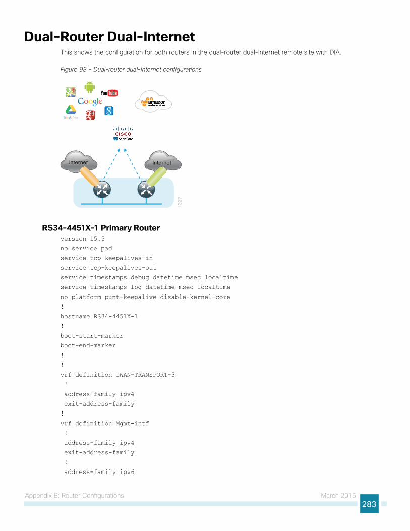
Appendix B: Router Configurations March 2015283
Dual-Router Dual-InternetThis shows the configuration for both routers in the dual-router dual-Internet remote site with DIA.
Figure 98 - Dual-router dual-Internet configurations
13
27
Internet Internet
RS34-4451X-1 Primary Routerversion 15.5
no service pad
service tcp-keepalives-in
service tcp-keepalives-out
service timestamps debug datetime msec localtime
service timestamps log datetime msec localtime
no platform punt-keepalive disable-kernel-core
!
hostname RS34-4451X-1
!
boot-start-marker
boot-end-marker
!
!
vrf definition IWAN-TRANSPORT-3
!
address-family ipv4
exit-address-family
!
vrf definition Mgmt-intf
!
address-family ipv4
exit-address-family
!
address-family ipv6
Appendix B: Router Configurations March 2015284
exit-address-family
!
enable secret 5 $1$S7wW$LwAu9mADPzeXE.yQjFmIc1
!
aaa new-model
!
!
aaa group server tacacs+ TACACS-SERVERS
server name TACACS-SERVER-1
!
aaa authentication login default group TACACS-SERVERS local
aaa authorization console
aaa authorization exec default group TACACS-SERVERS local
!
aaa session-id common
clock timezone PST -8 0
clock summer-time PDT recurring
!
!
!
ip domain name cisco.local
ip multicast-routing distributed
!
!
parameter-map type inspect global
log dropped-packets
multilink bundle-name authenticated
!
flow record Record-FNF-IWAN
description Flexible NetFlow for IWAN Monitoring
match ipv4 tos
match ipv4 protocol
match ipv4 source address
match ipv4 destination address
match transport source-port
match transport destination-port
match interface input
match flow direction
collect routing source as
collect routing destination as
collect routing next-hop address ipv4
collect ipv4 dscp
collect ipv4 id
collect ipv4 source prefix
collect ipv4 source mask
collect ipv4 destination mask
collect transport tcp flags
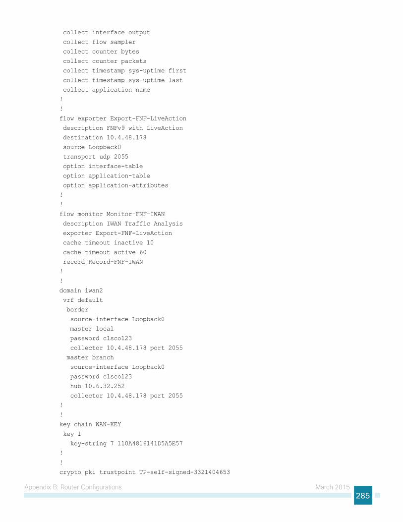
Appendix B: Router Configurations March 2015285
collect interface output
collect flow sampler
collect counter bytes
collect counter packets
collect timestamp sys-uptime first
collect timestamp sys-uptime last
collect application name
!
!
flow exporter Export-FNF-LiveAction
description FNFv9 with LiveAction
destination 10.4.48.178
source Loopback0
transport udp 2055
option interface-table
option application-table
option application-attributes
!
!
flow monitor Monitor-FNF-IWAN
description IWAN Traffic Analysis
exporter Export-FNF-LiveAction
cache timeout inactive 10
cache timeout active 60
record Record-FNF-IWAN
!
!
domain iwan2
vrf default
border
source-interface Loopback0
master local
password c1sco123
collector 10.4.48.178 port 2055
master branch
source-interface Loopback0
password c1sco123
hub 10.6.32.252
collector 10.4.48.178 port 2055
!
!
key chain WAN-KEY
key 1
key-string 7 110A4816141D5A5E57
!
!
crypto pki trustpoint TP-self-signed-3321404653
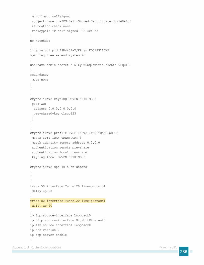
Appendix B: Router Configurations March 2015286
enrollment selfsigned
subject-name cn=IOS-Self-Signed-Certificate-3321404653
revocation-check none
rsakeypair TP-self-signed-3321404653
!
no watchdog
!
license udi pid ISR4451-X/K9 sn FOC1832ACNH
spanning-tree extend system-id
!
username admin secret 5 $1$yCu6$q6emTtaou/8c6tnJVFqul0
!
redundancy
mode none
!
!
!
crypto ikev2 keyring DMVPN-KEYRING-3
peer ANY
address 0.0.0.0 0.0.0.0
pre-shared-key c1sco123
!
!
!
crypto ikev2 profile FVRF-IKEv2-IWAN-TRANSPORT-3
match fvrf IWAN-TRANSPORT-3
match identity remote address 0.0.0.0
authentication remote pre-share
authentication local pre-share
keyring local DMVPN-KEYRING-3
!
crypto ikev2 dpd 40 5 on-demand
!
!
!
track 50 interface Tunnel20 line-protocol
delay up 20
!
track 80 interface Tunnel20 line-protocol
delay up 20
!
ip ftp source-interface Loopback0
ip tftp source-interface GigabitEthernet0
ip ssh source-interface Loopback0
ip ssh version 2
ip scp server enable
!
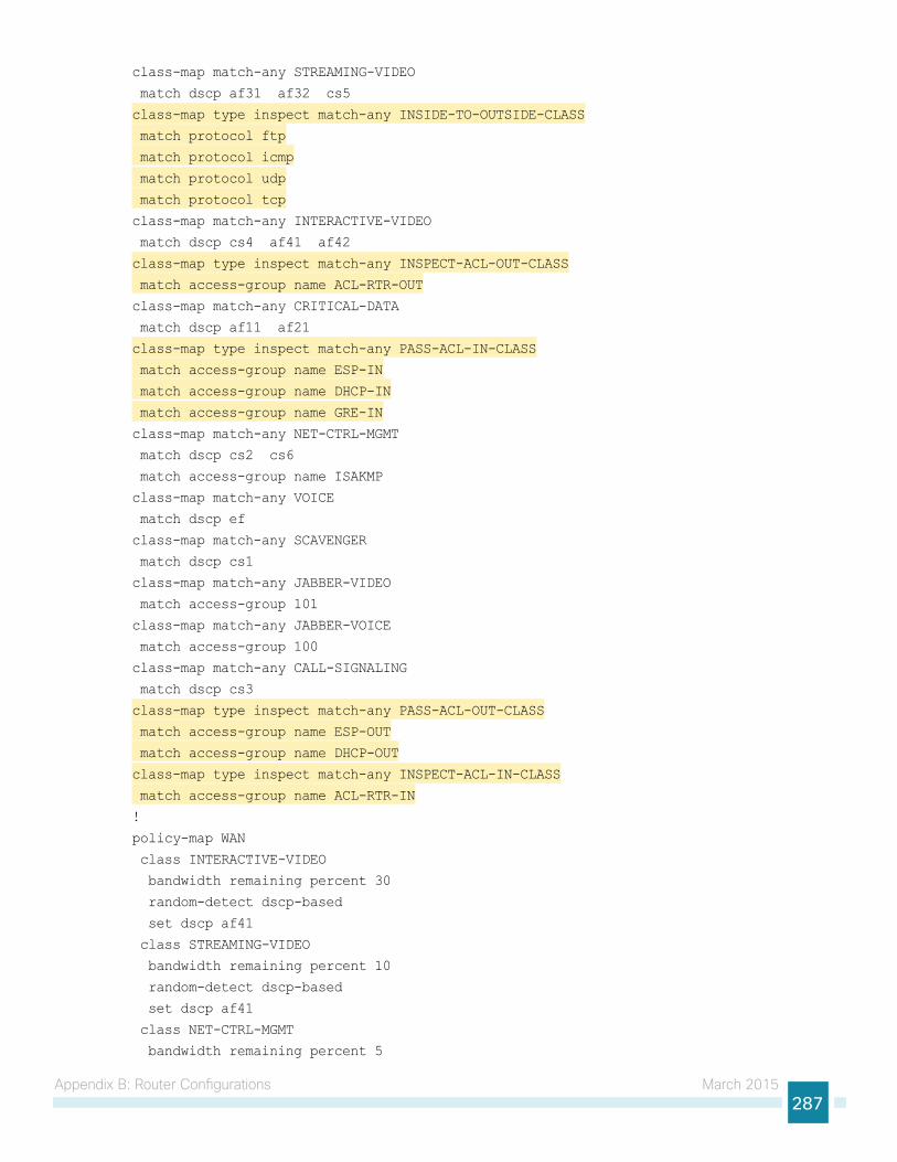
Appendix B: Router Configurations March 2015287
class-map match-any STREAMING-VIDEO
match dscp af31 af32 cs5
class-map type inspect match-any INSIDE-TO-OUTSIDE-CLASS
match protocol ftp
match protocol icmp
match protocol udp
match protocol tcp
class-map match-any INTERACTIVE-VIDEO
match dscp cs4 af41 af42
class-map type inspect match-any INSPECT-ACL-OUT-CLASS
match access-group name ACL-RTR-OUT
class-map match-any CRITICAL-DATA
match dscp af11 af21
class-map type inspect match-any PASS-ACL-IN-CLASS
match access-group name ESP-IN
match access-group name DHCP-IN
match access-group name GRE-IN
class-map match-any NET-CTRL-MGMT
match dscp cs2 cs6
match access-group name ISAKMP
class-map match-any VOICE
match dscp ef
class-map match-any SCAVENGER
match dscp cs1
class-map match-any JABBER-VIDEO
match access-group 101
class-map match-any JABBER-VOICE
match access-group 100
class-map match-any CALL-SIGNALING
match dscp cs3
class-map type inspect match-any PASS-ACL-OUT-CLASS
match access-group name ESP-OUT
match access-group name DHCP-OUT
class-map type inspect match-any INSPECT-ACL-IN-CLASS
match access-group name ACL-RTR-IN
!
policy-map WAN
class INTERACTIVE-VIDEO
bandwidth remaining percent 30
random-detect dscp-based
set dscp af41
class STREAMING-VIDEO
bandwidth remaining percent 10
random-detect dscp-based
set dscp af41
class NET-CTRL-MGMT
bandwidth remaining percent 5
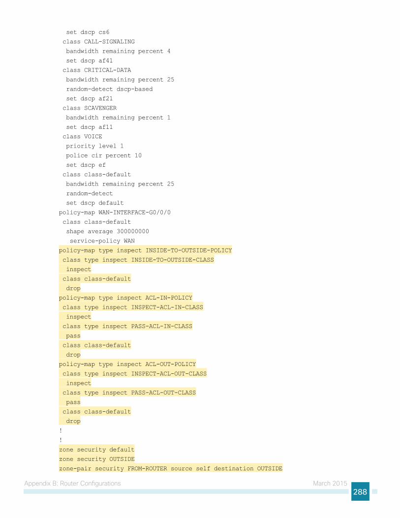
Appendix B: Router Configurations March 2015288
set dscp cs6
class CALL-SIGNALING
bandwidth remaining percent 4
set dscp af41
class CRITICAL-DATA
bandwidth remaining percent 25
random-detect dscp-based
set dscp af21
class SCAVENGER
bandwidth remaining percent 1
set dscp af11
class VOICE
priority level 1
police cir percent 10
set dscp ef
class class-default
bandwidth remaining percent 25
random-detect
set dscp default
policy-map WAN-INTERFACE-G0/0/0
class class-default
shape average 300000000
service-policy WAN
policy-map type inspect INSIDE-TO-OUTSIDE-POLICY
class type inspect INSIDE-TO-OUTSIDE-CLASS
inspect
class class-default
drop
policy-map type inspect ACL-IN-POLICY
class type inspect INSPECT-ACL-IN-CLASS
inspect
class type inspect PASS-ACL-IN-CLASS
pass
class class-default
drop
policy-map type inspect ACL-OUT-POLICY
class type inspect INSPECT-ACL-OUT-CLASS
inspect
class type inspect PASS-ACL-OUT-CLASS
pass
class class-default
drop
!
!
zone security default
zone security OUTSIDE
zone-pair security FROM-ROUTER source self destination OUTSIDE
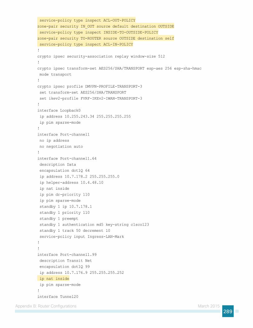
Appendix B: Router Configurations March 2015289
service-policy type inspect ACL-OUT-POLICY
zone-pair security IN_OUT source default destination OUTSIDE
service-policy type inspect INSIDE-TO-OUTSIDE-POLICY
zone-pair security TO-ROUTER source OUTSIDE destination self
service-policy type inspect ACL-IN-POLICY
!
crypto ipsec security-association replay window-size 512
!
crypto ipsec transform-set AES256/SHA/TRANSPORT esp-aes 256 esp-sha-hmac
mode transport
!
crypto ipsec profile DMVPN-PROFILE-TRANSPORT-3
set transform-set AES256/SHA/TRANSPORT
set ikev2-profile FVRF-IKEv2-IWAN-TRANSPORT-3
!
interface Loopback0
ip address 10.255.243.34 255.255.255.255
ip pim sparse-mode
!
interface Port-channel1
no ip address
no negotiation auto
!
interface Port-channel1.64
description Data
encapsulation dot1Q 64
ip address 10.7.178.2 255.255.255.0
ip helper-address 10.4.48.10
ip nat inside
ip pim dr-priority 110
ip pim sparse-mode
standby 1 ip 10.7.178.1
standby 1 priority 110
standby 1 preempt
standby 1 authentication md5 key-string c1sco123
standby 1 track 50 decrement 10
service-policy input Ingress-LAN-Mark
!
!
interface Port-channel1.99
description Transit Net
encapsulation dot1Q 99
ip address 10.7.176.9 255.255.255.252
ip nat inside
ip pim sparse-mode
!
interface Tunnel20
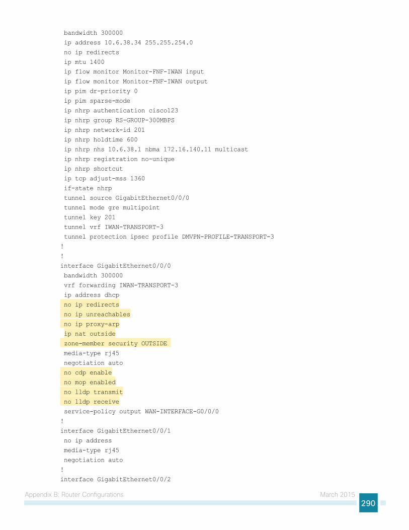
Appendix B: Router Configurations March 2015290
bandwidth 300000
ip address 10.6.38.34 255.255.254.0
no ip redirects
ip mtu 1400
ip flow monitor Monitor-FNF-IWAN input
ip flow monitor Monitor-FNF-IWAN output
ip pim dr-priority 0
ip pim sparse-mode
ip nhrp authentication cisco123
ip nhrp group RS-GROUP-300MBPS
ip nhrp network-id 201
ip nhrp holdtime 600
ip nhrp nhs 10.6.38.1 nbma 172.16.140.11 multicast
ip nhrp registration no-unique
ip nhrp shortcut
ip tcp adjust-mss 1360
if-state nhrp
tunnel source GigabitEthernet0/0/0
tunnel mode gre multipoint
tunnel key 201
tunnel vrf IWAN-TRANSPORT-3
tunnel protection ipsec profile DMVPN-PROFILE-TRANSPORT-3
!
!
interface GigabitEthernet0/0/0
bandwidth 300000
vrf forwarding IWAN-TRANSPORT-3
ip address dhcp
no ip redirects
no ip unreachables
no ip proxy-arp
ip nat outside
zone-member security OUTSIDE
media-type rj45
negotiation auto
no cdp enable
no mop enabled
no lldp transmit
no lldp receive
service-policy output WAN-INTERFACE-G0/0/0
!
interface GigabitEthernet0/0/1
no ip address
media-type rj45
negotiation auto
!
interface GigabitEthernet0/0/2
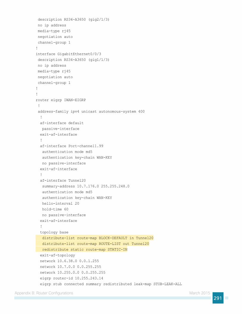
Appendix B: Router Configurations March 2015291
description RS34-A3650 (gig2/1/3)
no ip address
media-type rj45
negotiation auto
channel-group 1
!
interface GigabitEthernet0/0/3
description RS34-A3650 (gig1/1/3)
no ip address
media-type rj45
negotiation auto
channel-group 1
!
!
router eigrp IWAN-EIGRP
!
address-family ipv4 unicast autonomous-system 400
!
af-interface default
passive-interface
exit-af-interface
!
af-interface Port-channel1.99
authentication mode md5
authentication key-chain WAN-KEY
no passive-interface
exit-af-interface
!
af-interface Tunnel20
summary-address 10.7.176.0 255.255.248.0
authentication mode md5
authentication key-chain WAN-KEY
hello-interval 20
hold-time 60
no passive-interface
exit-af-interface
!
topology base
distribute-list route-map BLOCK-DEFAULT in Tunnel20
distribute-list route-map ROUTE-LIST out Tunnel20
redistribute static route-map STATIC-IN
exit-af-topology
network 10.6.38.0 0.0.1.255
network 10.7.0.0 0.0.255.255
network 10.255.0.0 0.0.255.255
eigrp router-id 10.255.243.14
eigrp stub connected summary redistributed leak-map STUB-LEAK-ALL
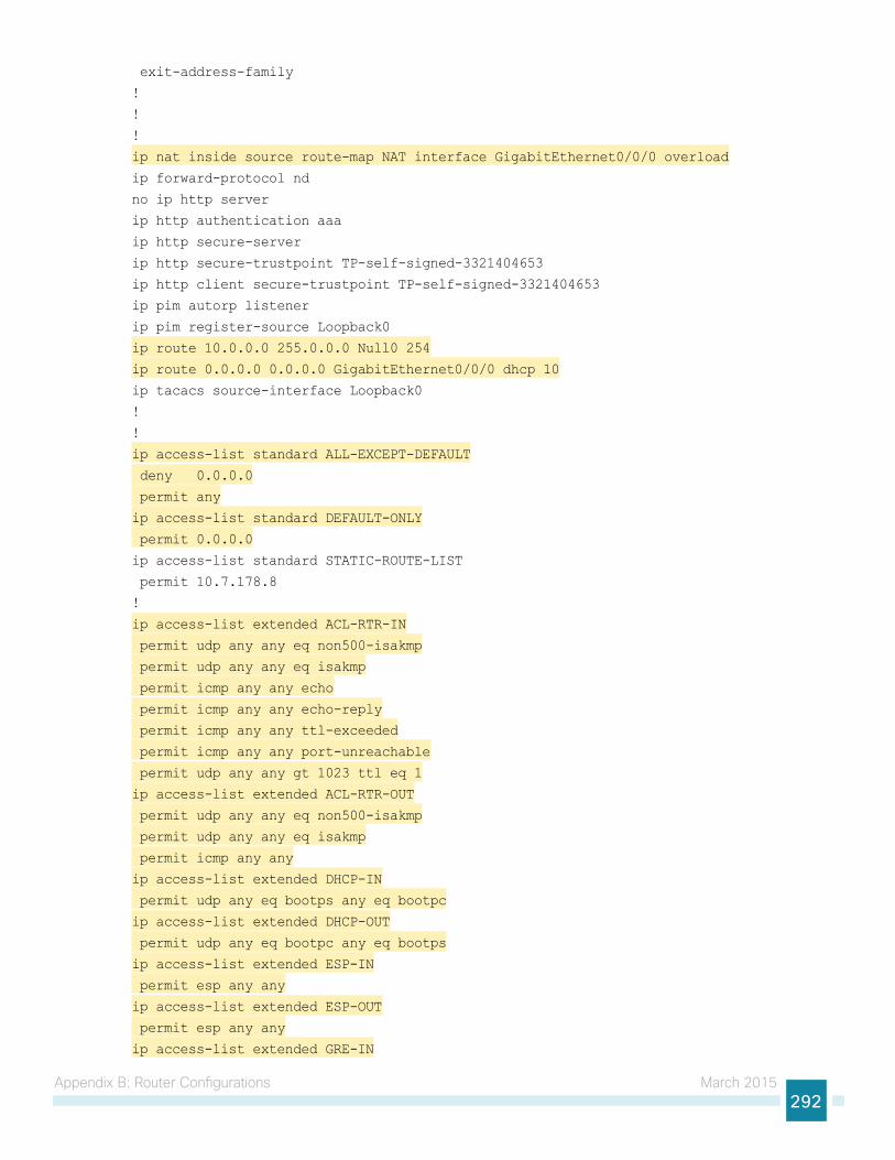
Appendix B: Router Configurations March 2015292
exit-address-family
!
!
!
ip nat inside source route-map NAT interface GigabitEthernet0/0/0 overload
ip forward-protocol nd
no ip http server
ip http authentication aaa
ip http secure-server
ip http secure-trustpoint TP-self-signed-3321404653
ip http client secure-trustpoint TP-self-signed-3321404653
ip pim autorp listener
ip pim register-source Loopback0
ip route 10.0.0.0 255.0.0.0 Null0 254
ip route 0.0.0.0 0.0.0.0 GigabitEthernet0/0/0 dhcp 10
ip tacacs source-interface Loopback0
!
!
ip access-list standard ALL-EXCEPT-DEFAULT
deny 0.0.0.0
permit any
ip access-list standard DEFAULT-ONLY
permit 0.0.0.0
ip access-list standard STATIC-ROUTE-LIST
permit 10.7.178.8
!
ip access-list extended ACL-RTR-IN
permit udp any any eq non500-isakmp
permit udp any any eq isakmp
permit icmp any any echo
permit icmp any any echo-reply
permit icmp any any ttl-exceeded
permit icmp any any port-unreachable
permit udp any any gt 1023 ttl eq 1
ip access-list extended ACL-RTR-OUT
permit udp any any eq non500-isakmp
permit udp any any eq isakmp
permit icmp any any
ip access-list extended DHCP-IN
permit udp any eq bootps any eq bootpc
ip access-list extended DHCP-OUT
permit udp any eq bootpc any eq bootps
ip access-list extended ESP-IN
permit esp any any
ip access-list extended ESP-OUT
permit esp any any
ip access-list extended GRE-IN
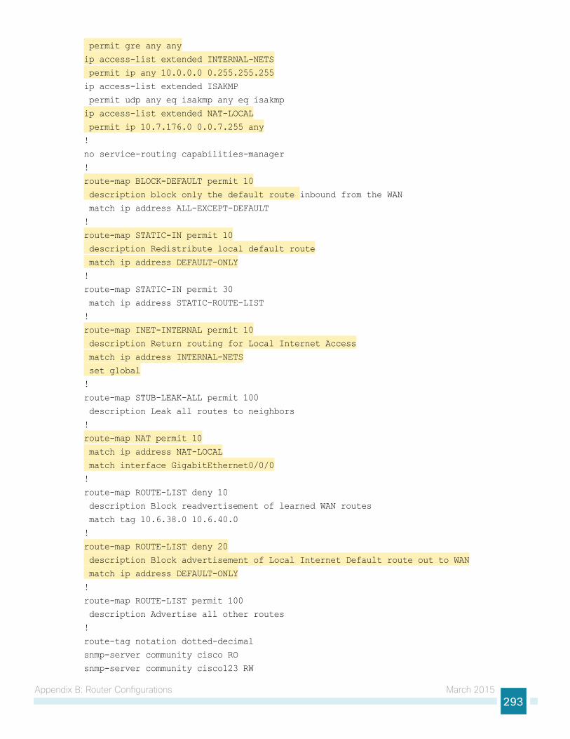
Appendix B: Router Configurations March 2015293
permit gre any any
ip access-list extended INTERNAL-NETS
permit ip any 10.0.0.0 0.255.255.255
ip access-list extended ISAKMP
permit udp any eq isakmp any eq isakmp
ip access-list extended NAT-LOCAL
permit ip 10.7.176.0 0.0.7.255 any
!
no service-routing capabilities-manager
!
route-map BLOCK-DEFAULT permit 10
description block only the default route inbound from the WAN
match ip address ALL-EXCEPT-DEFAULT
!
route-map STATIC-IN permit 10
description Redistribute local default route
match ip address DEFAULT-ONLY
!
route-map STATIC-IN permit 30
match ip address STATIC-ROUTE-LIST
!
route-map INET-INTERNAL permit 10
description Return routing for Local Internet Access
match ip address INTERNAL-NETS
set global
!
route-map STUB-LEAK-ALL permit 100
description Leak all routes to neighbors
!
route-map NAT permit 10
match ip address NAT-LOCAL
match interface GigabitEthernet0/0/0
!
route-map ROUTE-LIST deny 10
description Block readvertisement of learned WAN routes
match tag 10.6.38.0 10.6.40.0
!
route-map ROUTE-LIST deny 20
description Block advertisement of Local Internet Default route out to WAN
match ip address DEFAULT-ONLY
!
route-map ROUTE-LIST permit 100
description Advertise all other routes
!
route-tag notation dotted-decimal
snmp-server community cisco RO
snmp-server community cisco123 RW
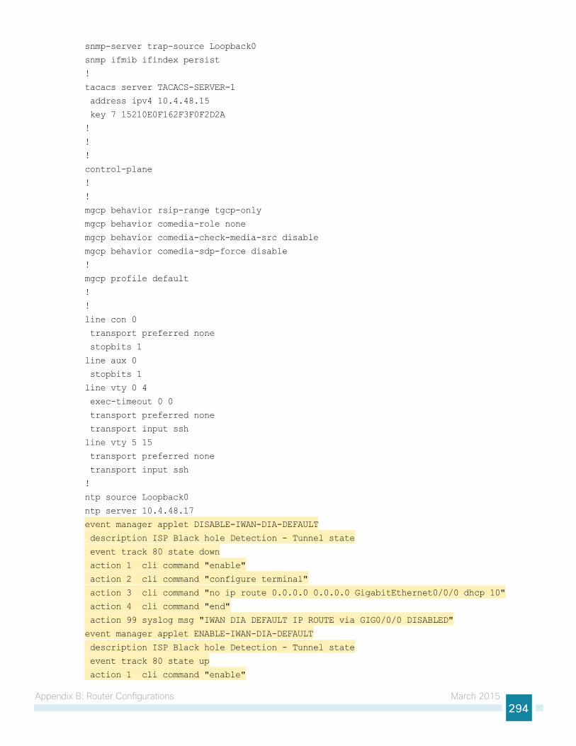
Appendix B: Router Configurations March 2015294
snmp-server trap-source Loopback0
snmp ifmib ifindex persist
!
tacacs server TACACS-SERVER-1
address ipv4 10.4.48.15
key 7 15210E0F162F3F0F2D2A
!
!
!
control-plane
!
!
mgcp behavior rsip-range tgcp-only
mgcp behavior comedia-role none
mgcp behavior comedia-check-media-src disable
mgcp behavior comedia-sdp-force disable
!
mgcp profile default
!
!
line con 0
transport preferred none
stopbits 1
line aux 0
stopbits 1
line vty 0 4
exec-timeout 0 0
transport preferred none
transport input ssh
line vty 5 15
transport preferred none
transport input ssh
!
ntp source Loopback0
ntp server 10.4.48.17
event manager applet DISABLE-IWAN-DIA-DEFAULT
description ISP Black hole Detection - Tunnel state
event track 80 state down
action 1 cli command "enable"
action 2 cli command "configure terminal"
action 3 cli command "no ip route 0.0.0.0 0.0.0.0 GigabitEthernet0/0/0 dhcp 10"
action 4 cli command "end"
action 99 syslog msg "IWAN DIA DEFAULT IP ROUTE via GIG0/0/0 DISABLED"
event manager applet ENABLE-IWAN-DIA-DEFAULT
description ISP Black hole Detection - Tunnel state
event track 80 state up
action 1 cli command "enable"

Appendix B: Router Configurations March 2015295
action 2 cli command "configure terminal"
action 3 cli command "ip route 0.0.0.0 0.0.0.0 GigabitEthernet0/0/0 dhcp 10"
action 4 cli command "end"
action 99 syslog msg "IWAN DIA DEFAULT IP ROUTE via GIG0/0/0 ENABLED"
!
end
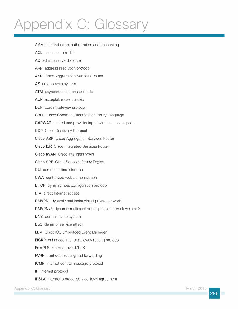
Appendix C: Glossary March 2015296
Appendix C: GlossaryAAA authentication, authorization and accounting
ACL access control list
AD administrative distance
ARP address resolution protocol
ASR Cisco Aggregation Services Router
AS autonomous system
ATM asynchronous transfer mode
AUP acceptable use policies
BGP border gateway protocol
C3PL Cisco Common Classification Policy Language
CAPWAP control and provisioning of wireless access points
CDP Cisco Discovery Protocol
Cisco ASR Cisco Aggregation Services Router
Cisco ISR Cisco Integrated Services Router
Cisco IWAN Cisco Intelligent WAN
Cisco SRE Cisco Services Ready Engine
CLI command-line interface
CWA centralized web authentication
DHCP dynamic host configuration protocol
DIA direct Internet access
DMVPN dynamic multipoint virtual private network
DMVPNv3 dynamic multipoint virtual private network version 3
DNS domain name system
DoS denial of service attack
EEM Cisco IOS Embedded Event Manager
EIGRP enhanced interior gateway routing protocol
EoMPLS Ethernet over MPLS
FVRF front door routing and forwarding
ICMP Internet control message protocol
IP Internet protocol
IPSLA Internet protocol service-level agreement
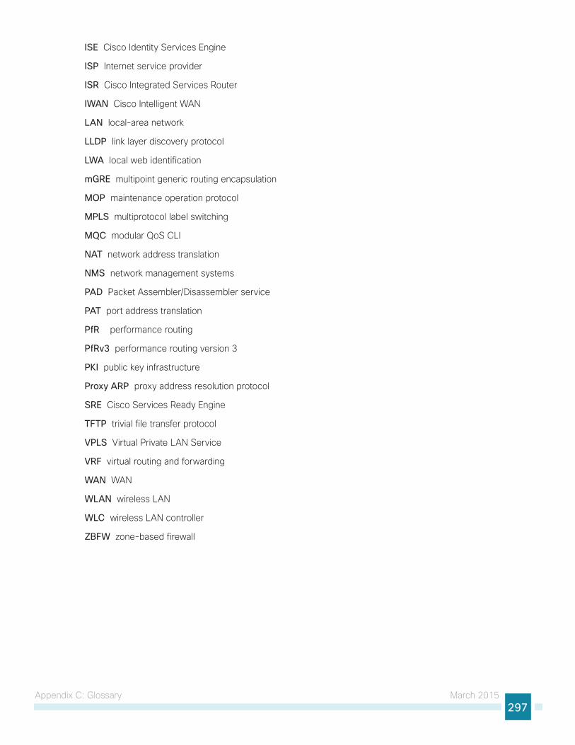
Appendix C: Glossary March 2015297
ISE Cisco Identity Services Engine
ISP Internet service provider
ISR Cisco Integrated Services Router
IWAN Cisco Intelligent WAN
LAN local-area network
LLDP link layer discovery protocol
LWA local web identification
mGRE multipoint generic routing encapsulation
MOP maintenance operation protocol
MPLS multiprotocol label switching
MQC modular QoS CLI
NAT network address translation
NMS network management systems
PAD Packet Assembler/Disassembler service
PAT port address translation
PfR performance routing
PfRv3 performance routing version 3
PKI public key infrastructure
Proxy ARP proxy address resolution protocol
SRE Cisco Services Ready Engine
TFTP trivial file transfer protocol
VPLS Virtual Private LAN Service
VRF virtual routing and forwarding
WAN WAN
WLAN wireless LAN
WLC wireless LAN controller
ZBFW zone-based firewall
Americas HeadquartersCisco Systems, Inc.San Jose, CA
Asia Pacific HeadquartersCisco Systems (USA) Pte. Ltd.Singapore
Europe HeadquartersCisco Systems International BV Amsterdam,The Netherlands
Cisco has more than 200 offices worldwide. Addresses, phone numbers, and fax numbers are listed on the Cisco Website at www.cisco.com/go/offices.
ALL DESIGNS, SPECIFICATIONS, STATEMENTS, INFORMATION, AND RECOMMENDATIONS (COLLECTIVELY, “DESIGNS”) IN THIS MANUAL ARE PRESENTED “AS IS,” WITH ALL FAULTS. CISCO AND ITS SUPPLIERS DISCLAIM ALL WARRANTIES, INCLUDING, WITHOUT LIMITATION, THE WARRANTY OF MERCHANTABILITY, FITNESS FOR A PARTICULAR PURPOSE AND NONINFRINGEMENT OR ARISING FROM A COURSE OF DEALING, USAGE, OR TRADE PRACTICE. IN NO EVENT SHALL CISCO OR ITS SUPPLIERS BE LIABLE FOR ANY INDIRECT, SPECIAL, CONSEQUENTIAL, OR INCIDENTAL DAMAGES, INCLUDING, WITHOUT LIMITATION, LOST PROFITS OR LOSS OR DAMAGE TO DATA ARISING OUT OF THE USE OR INABILITY TO USE THE DESIGNS, EVEN IF CISCO OR ITS SUPPLIERS HAVE BEEN ADVISED OF THE POSSIBILITY OF SUCH DAMAGES. THE DESIGNS ARE SUBJECT TO CHANGE WITHOUT NOTICE. USERS ARE SOLELY RESPONSIBLE FOR THEIR APPLICATION OF THE DESIGNS. THE DESIGNS DO NOT CONSTITUTE THE TECHNICAL OR OTHER PROFESSIONAL ADVICE OF CISCO, ITS SUPPLIERS OR PARTNERS. USERS SHOULD CONSULT THEIR OWN TECHNICAL ADVISORS BEFORE IMPLEMENTING THE DESIGNS. RESULTS MAY VARY DEPENDING ON FACTORS NOT TESTED BY CISCO.
Any Internet Protocol (IP) addresses used in this document are not intended to be actual addresses. Any examples, command display output, and figures included in the document are shown for illustrative purposes only. Any use of actual IP addresses in illustrative content is unintentional and coincidental.
© 2015 Cisco Systems, Inc. All rights reserved.
Cisco and the Cisco logo are trademarks or registered trademarks of Cisco and/or its affiliates in the U.S. and other countries. To view a list of Cisco trademarks, go to this URL: www.cisco.com/go/trademarks. Third-party trademarks mentioned are the property of their respective owners. The use of the word partner does not imply a partnership relationship between Cisco and any other company. (1110R)
Please use the feedback form to send comments and suggestions about this guide.
Feedback
B-0000220i-2 08/16