Embed Size (px)
Citation preview
iVMS-4000(V2.0)
User Manual
User Manual of iVMS-4000(v2.0)
1
Table of Contents
Chapter 1 Welcome to iVMS-4000 (V2.0) ....................................................................................................... 4
1.1 Overview .............................................................................................................................................. 4
1.2 Computer Disposition Request ............................................................................................................. 4
1.3 Convention ........................................................................................................................................... 4
Chapter 2 Install & Uninstall ........................................................................................................................... 5
2.1 Install the Software .............................................................................................................................. 5
2.2 Uninstall Software ................................................................................................................................ 6
Chapter 3 Basic Operations ............................................................................................................................. 7
3.1. User Registration ................................................................................................................................. 7
3.2 User Login ........................................................................................................................................... 10
3.3 GUI Introduction ................................................................................................................................. 11
Chapter 4 Device Management .................................................................................................................... 14
4.1 Area Configuration ............................................................................................................................. 14
4.2 Add Device ......................................................................................................................................... 15
4.3 Channel Configuration ........................................................................................................................ 17
4.4 Channel Configuration of DS-9000 Series DVR ................................................................................... 18
4.5 Stream Media Server Configuration ................................................................................................... 20
4.6 Group Configuration ........................................................................................................................... 20
4.6.1 Sort by group ........................................................................................................................... 20
4.6.2 Channel ................................................................................................................................... 21
4.7 Sort by Camera Configuration ............................................................................................................ 22
Chapter 5 Preview ......................................................................................................................................... 23
5.1 Non-cycle Preview .............................................................................................................................. 24
5.1.1 Play by Node ............................................................................................................................ 24
5.1.2 Sort by Camera Preview .......................................................................................................... 24
5.1.3 Stop Playing ............................................................................................................................. 25
5.2 Cycle Play ............................................................................................................................................ 25
5.2.1 Cycle Configuration ................................................................................................................. 25
5.2.2 Cycle Play of Device/Group ..................................................................................................... 26
5.2.3 Mixed Cycle ............................................................................................................................. 27
5.3 Preview Control .................................................................................................................................. 28
5.4 Two Screen Preview ........................................................................................................................... 29
5.5 Recording & Capture .......................................................................................................................... 30
5.5.1 Recording ................................................................................................................................. 30
5.5.2 Capture .................................................................................................................................... 31
5.6 Hardware Decode ............................................................................................................................... 32
5.6.1 Hardware Decode Configure introduce ................................................................................... 32
5.6.2 Hardware Decode Mode Configuration ................................................................................... 33
5.6.3 Hardware Decode Output Window Configuration .................................................................. 34
5.6.4 Hardware Decode Preview ...................................................................................................... 35
User Manual of iVMS-4000(v2.0)
2
5.6.5 Secondary Output of Hardware Decode .................................................................................. 36
5.7 Others ................................................................................................................................................. 37
5.7.1 Voice Talk & Broadcast ............................................................................................................ 37
5.7.2 Audio Broadcast ...................................................................................................................... 38
5.7.3 Alarm Output Control .............................................................................................................. 38
5.7.4 Device Status ........................................................................................................................... 38
5.7.5 Remote Control Panel .............................................................................................................. 39
Chapter 6 PTZ Control ................................................................................................................................... 40
6.1 RS-485 Parameters Configuration ....................................................................................................... 40
6.2 PTZ Control ......................................................................................................................................... 40
6.3 Partial Zoom ....................................................................................................................................... 41
6.4 Preset ................................................................................................................................................. 41
6.5 Patrol .................................................................................................................................................. 42
6.6 Video Parameters Configuration ........................................................................................................ 43
6.7 Keyboard and Joystick Control ........................................................................................................... 44
6.8 PTZ Control by Joystick ....................................................................................................................... 45
Chapter 7 Recording ..................................................................................................................................... 46
7.1 Local Recording .................................................................................................................................. 46
7.1.1 Store setup .............................................................................................................................. 46
7.2 NVR Storage Server Recording Configuration ..................................................................................... 46
7.2.1 Add NVR Server ....................................................................................................................... 47
7.2.2 NVR Recording Mode Configuration ........................................................................................ 47
7.2.3 NVR Recording Schedule Configuration ................................................................................... 48
Chapter 8 Playback ........................................................................................................................................ 50
8.1 Remote VOD ....................................................................................................................................... 50
8.1.1 Remote VOD Query ................................................................................................................. 51
8.1.2 Playback Control ...................................................................................................................... 51
8.2 Local Playback .................................................................................................................................... 54
8.2.1 Local Playback Query ............................................................................................................... 55
8.2.2 Playback Control ...................................................................................................................... 56
8.3 Event Playback .................................................................................................................................... 57
8.3.1 Record search .......................................................................................................................... 58
8.3.2 Playback control ...................................................................................................................... 59
8.4 Dynamic Analyze ................................................................................................................................ 60
8.4.1 Record Search .......................................................................................................................... 60
8.4.2 Playback Control ...................................................................................................................... 61
Chapter 9 Remote Configuration .................................................................................................................. 63
9.1 Remote Device Configuration ............................................................................................................. 63
9.1.1 Remote Recording Configuration ............................................................................................ 64
9.1.2 Alarm ....................................................................................................................................... 70
9.1.3 Network Configuration ............................................................................................................ 78
9.1.4 Channel Configuration ............................................................................................................. 81
9.1.5 Account Management ............................................................................................................. 82
9.1.6 Others ...................................................................................................................................... 84
User Manual of iVMS-4000(v2.0)
3
9.2 iVMS-2000 Remote Configuration ...................................................................................................... 85
9.2.1 General Settings ...................................................................................................................... 86
9.2.2 Network Settings ..................................................................................................................... 86
9.2.3 Camera Settings ....................................................................................................................... 87
9.2.4 Schedule Settings .................................................................................................................... 87
9.2.5 Alarm Settings ......................................................................................................................... 88
9.2.6 User Settings ........................................................................................................................... 88
9.2.7 E-mail Settings ......................................................................................................................... 89
Chapter 10 Alarm Linkage ................................................................................................................................ 90
10.1 Linkage Configuration ....................................................................................................................... 90
10.2 Alarm Arming & Disarming ............................................................................................................... 91
Chapter 11 E-Map ........................................................................................................................................... 93
11.1 Add Map ........................................................................................................................................... 93
11.2 Map Configuration ........................................................................................................................... 94
11.2.1 Hot Spot ................................................................................................................................. 94
11.2.2 Hot Region ............................................................................................................................. 96
Chapter 12 Utilities ......................................................................................................................................... 98
12.1 Software Configuration .................................................................................................................... 98
12.2 Log Management ........................................................................................................................... 100
12.2.1 Log Query ............................................................................................................................ 100
12.2.2 Playback Linked Recordings ................................................................................................. 102
12.2.3 Export Log ............................................................................................................................ 103
12.3 User Management .......................................................................................................................... 103
12.3.1 Add & Delete User ............................................................................................................... 104
12.3.2 User Rights Distribution ....................................................................................................... 105
User Manual of iVMS-4000(v2.0)
4
Chapter 1 Welcome to iVMS-4000 (V2.0)
1.1 Overview
The iVMS-4000(V2.0) is the client application specially developed for the embedded DVR. It is applicable to DVR,
DVS, 7600 series NVR and hybrid NVR, 95/9600 series NVR, IP Camera, IP Dome, decode card and accessing iVMS-2000.
There may be technical inaccuracies, or typographical errors in the manual. The contents including description of
products and program will be updated without notice.
1.2 Computer Disposition Request
Operating System: Microsoft Windows 2000, XP, 2003, Vista
CPU: Intel Pentium IV 3.0 GHz or models above
RAM: 1G or above
Display: 1024×768 resolution or above
1.3 Convention
Conventions as follows in this manual:
DVR, DVS,NVR, IP Camera and IP Dome are all referred to as device
Click refers to left click mouse
Double click refers to double left click the mouse
User Manual of iVMS-4000(v2.0)
5
Chapter 2 Install & Uninstall
2.1 Install the Software
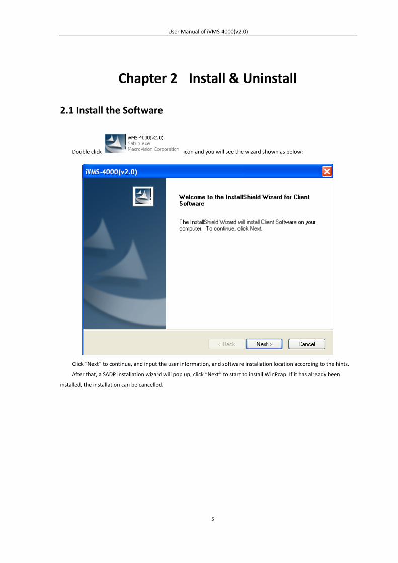
Double click icon and you will see the wizard shown as below:
Click “Next” to continue, and input the user information, and software installation location according to the hints.
After that, a SADP installation wizard will pop up; click “Next” to start to install WinPcap. If it has already been
installed, the installation can be cancelled.
User Manual of iVMS-4000(v2.0)
6
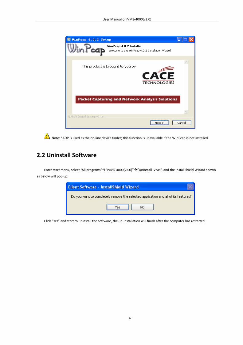
Note: SADP is used as the on-line device finder; this function is unavailable if the WinPcap is not installed.
2.2 Uninstall Software
Enter start menu, select “All programs””iVMS-4000(v2.0)””Uninstall iVMS”, and the InstallShield Wizard shown
as below will pop up:
Click “Yes” and start to uninstall the software, the un-installation will finish after the computer has restarted.
User Manual of iVMS-4000(v2.0)
7
Chapter 3 Basic Operations
Path: “Start””All Programs””iVMS-4000(v2.0)”” iVMS-4000(v2.0)”
3.1. User Registration
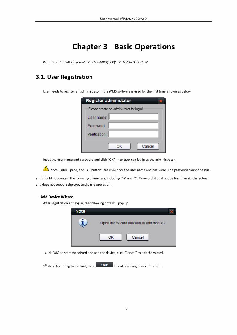
User needs to register an administrator if the iVMS software is used for the first time, shown as below:
Input the user name and password and click “OK”, then user can log in as the administrator.
Note: Enter, Space, and TAB buttons are invalid for the user name and password. The password cannot be null,
and should not contain the following characters, including “%” and “’”. Password should not be less than six characters
and does not support the copy and paste operation.
Add Device Wizard After registration and log in, the following note will pop up:
Click “OK” to start the wizard and add the device, click “Cancel” to exit the wizard.
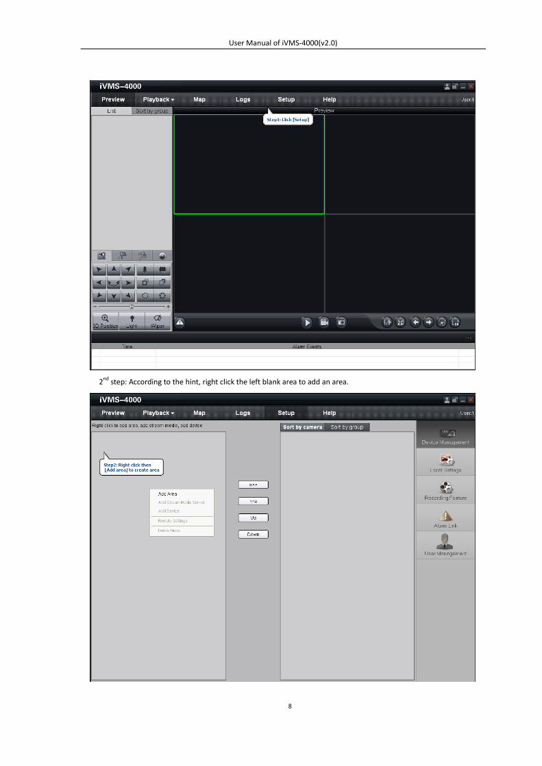
1st step: According to the hint, click to enter adding device interface.
User Manual of iVMS-4000(v2.0)
8
2nd step: According to the hint, right click the left blank area to add an area.
User Manual of iVMS-4000(v2.0)
9
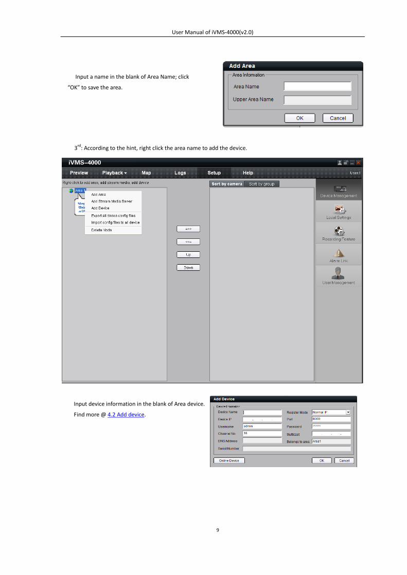
3rd: According to the hint, right click the area name to add the device.
Input device information in the blank of Area device.
Find more @ 4.2 Add device.
Input a name in the blank of Area Name; click
“OK” to save the area.
User Manual of iVMS-4000(v2.0)
10
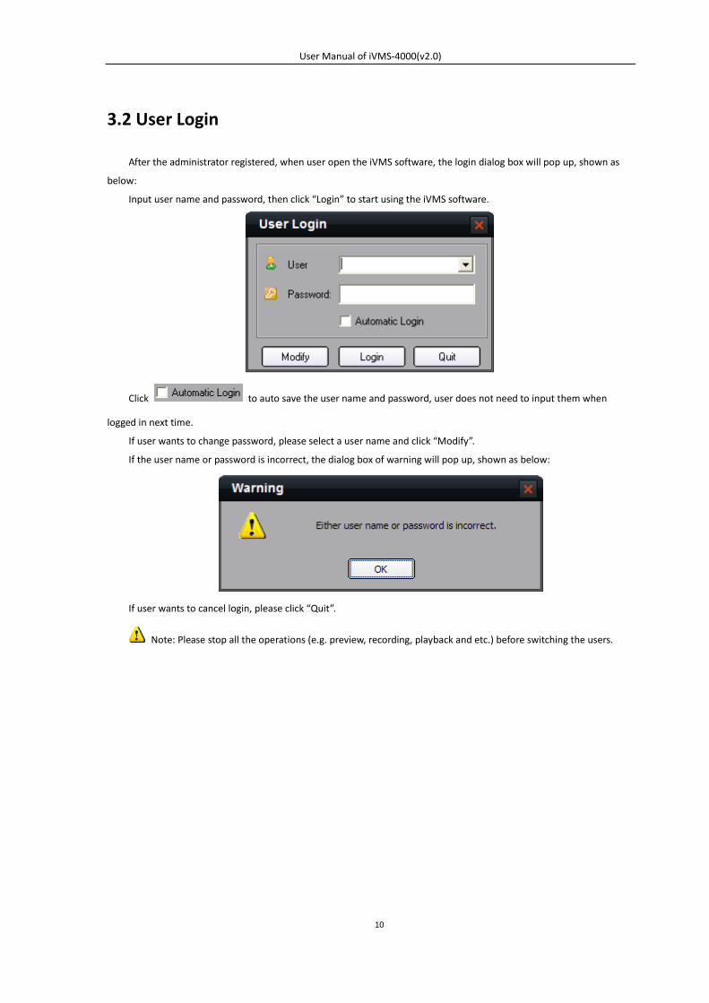
3.2 User Login
After the administrator registered, when user open the iVMS software, the login dialog box will pop up, shown as
below:
Input user name and password, then click “Login” to start using the iVMS software.
Click to auto save the user name and password, user does not need to input them when
logged in next time.
If user wants to change password, please select a user name and click “Modify”.
If the user name or password is incorrect, the dialog box of warning will pop up, shown as below:
If user wants to cancel login, please click “Quit”.
Note: Please stop all the operations (e.g. preview, recording, playback and etc.) before switching the users.
User Manual of iVMS-4000(v2.0)
11
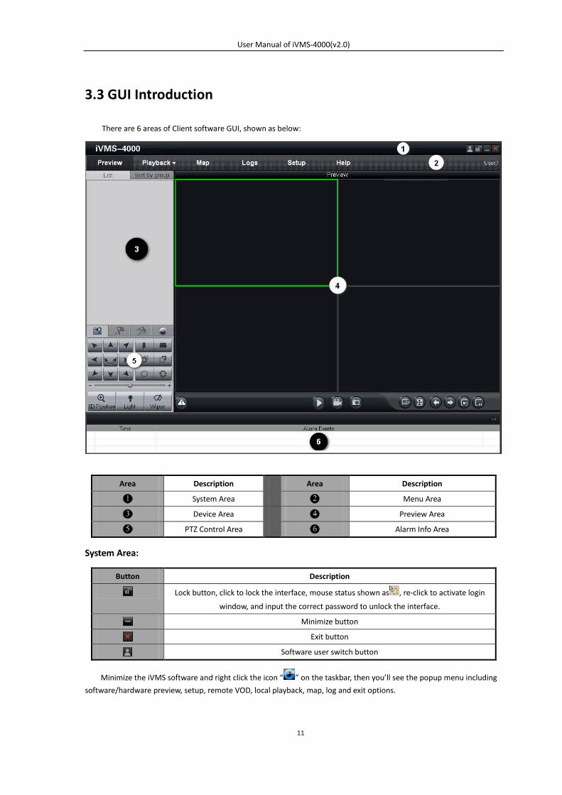
3.3 GUI Introduction
There are 6 areas of Client software GUI, shown as below:
Area Description Area Description
System Area Menu Area
Device Area Preview Area
PTZ Control Area Alarm Info Area
System Area:
Button Description
Lock button, click to lock the interface, mouse status shown as , re-click to activate login
window, and input the correct password to unlock the interface.
Minimize button
Exit button
Software user switch button
Minimize the iVMS software and right click the icon “ ” on the taskbar, then you’ll see the popup menu including
software/hardware preview, setup, remote VOD, local playback, map, log and exit options.
User Manual of iVMS-4000(v2.0)
12
Menu Area:
Area Description
Enter preview interface (If the decoding card is installed in PC, then enter the software
or hardware decoding interface)
Enter playback interface, including remote VOD and local playback
Enter e-map interface
Enter log query interface
Enter configure interface
Enter Help (user manual) and About (software info) menu
Device Area:
Mode Description
List Display by list
Sort by group Display by group
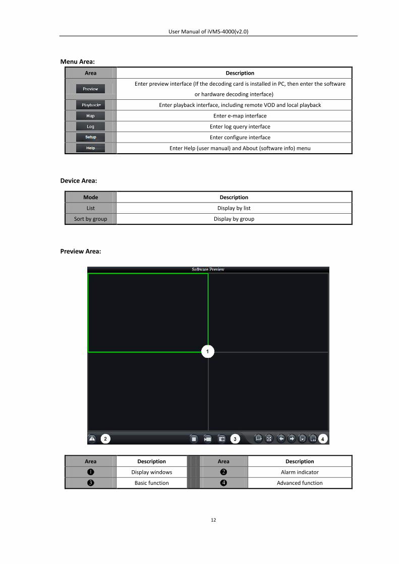
Preview Area:
Area Description Area Description
Display windows Alarm indicator
Basic function Advanced function
User Manual of iVMS-4000(v2.0)
13
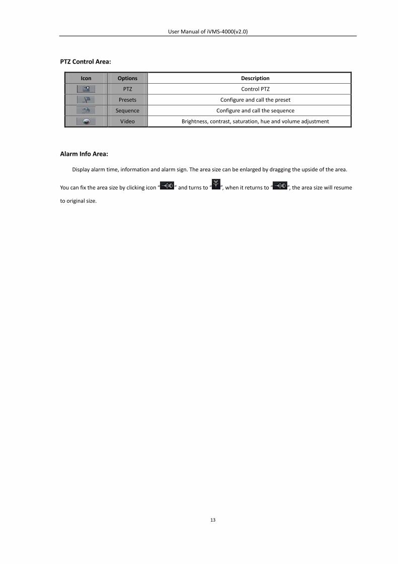
PTZ Control Area:
Icon Options Description
PTZ Control PTZ
Presets Configure and call the preset
Sequence Configure and call the sequence
Video Brightness, contrast, saturation, hue and volume adjustment
Alarm Info Area:
Display alarm time, information and alarm sign. The area size can be enlarged by dragging the upside of the area.
You can fix the area size by clicking icon “ ” and turns to “ ”, when it returns to “ ”, the area size will resume
to original size.
User Manual of iVMS-4000(v2.0)
14
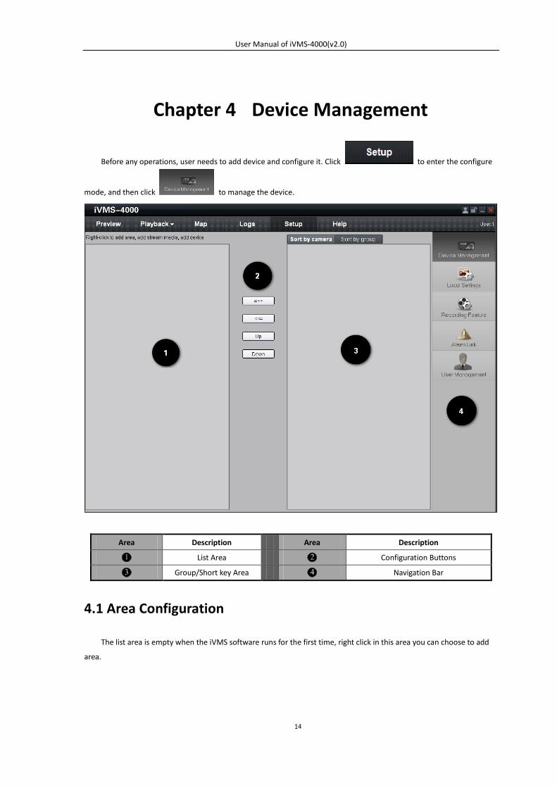
Chapter 4 Device Management
Before any operations, user needs to add device and configure it. Click to enter the configure
mode, and then click to manage the device.
Area Description Area Description
List Area Configuration Buttons
Group/Short key Area Navigation Bar
4.1 Area Configuration
The list area is empty when the iVMS software runs for the first time, right click in this area you can choose to add
area.
User Manual of iVMS-4000(v2.0)
15
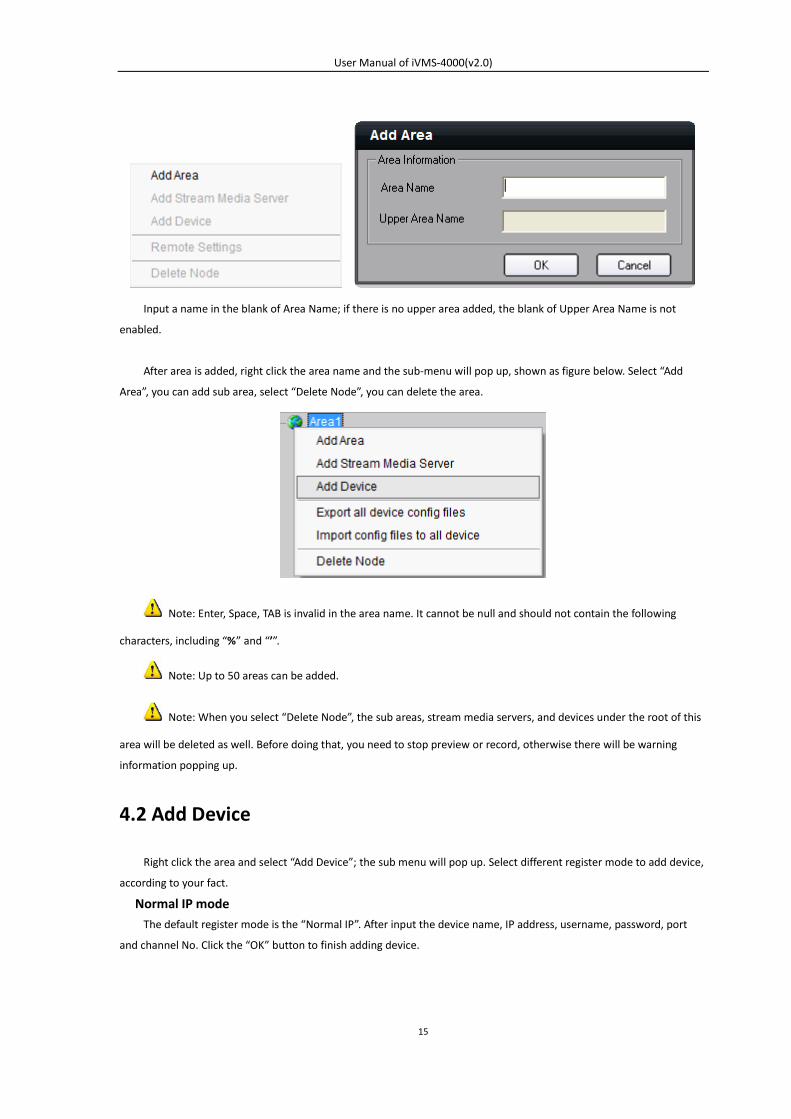
Input a name in the blank of Area Name; if there is no upper area added, the blank of Upper Area Name is not
enabled.
After area is added, right click the area name and the sub-menu will pop up, shown as figure below. Select “Add
Area”, you can add sub area, select “Delete Node”, you can delete the area.
Note: Enter, Space, TAB is invalid in the area name. It cannot be null and should not contain the following
characters, including “%” and “’”.
Note: Up to 50 areas can be added.
Note: When you select “Delete Node”, the sub areas, stream media servers, and devices under the root of this
area will be deleted as well. Before doing that, you need to stop preview or record, otherwise there will be warning
information popping up.
4.2 Add Device
Right click the area and select “Add Device”; the sub menu will pop up. Select different register mode to add device,
according to your fact.
Normal IP mode The default register mode is the “Normal IP”. After input the device name, IP address, username, password, port
and channel No. Click the “OK” button to finish adding device.
User Manual of iVMS-4000(v2.0)
16
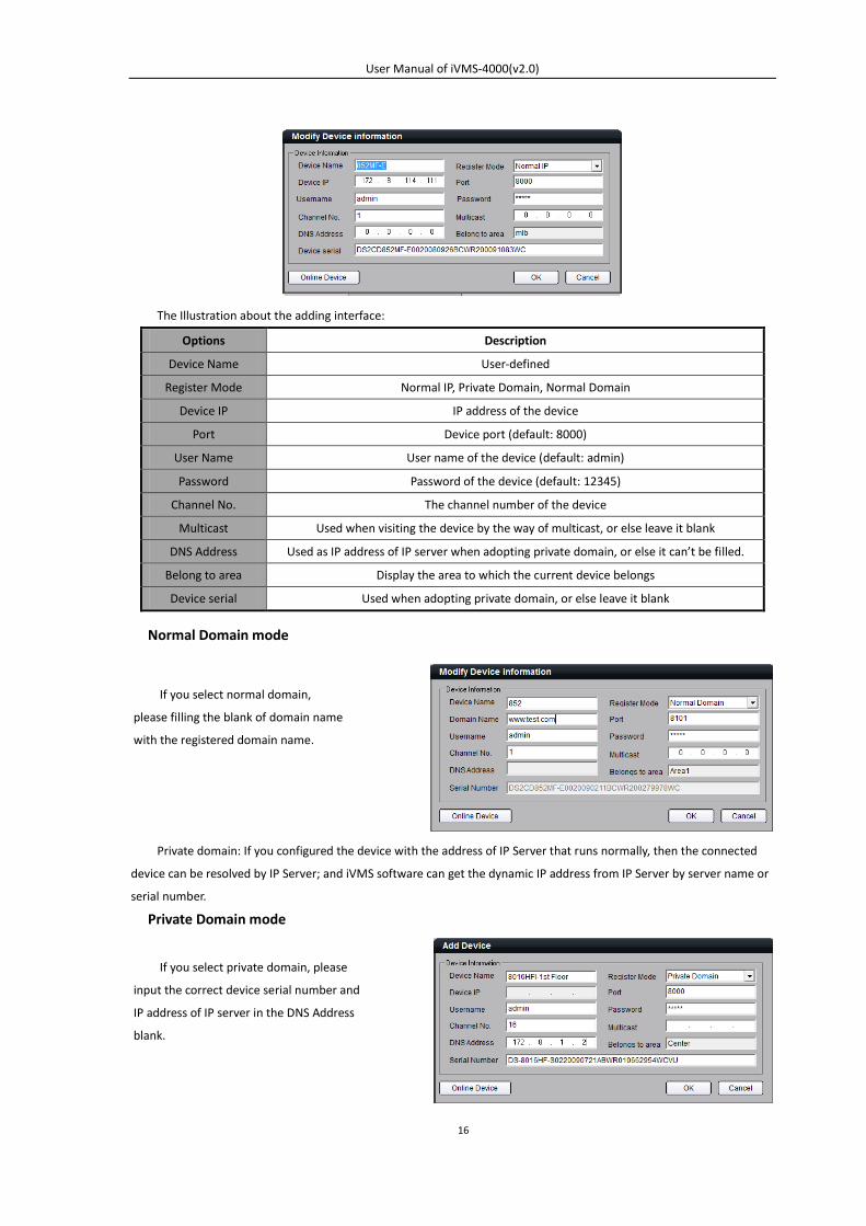
The Illustration about the adding interface:
Options Description
Device Name User-defined
Register Mode Normal IP, Private Domain, Normal Domain
Device IP IP address of the device
Port Device port (default: 8000)
User Name User name of the device (default: admin)
Password Password of the device (default: 12345)
Channel No. The channel number of the device
Multicast Used when visiting the device by the way of multicast, or else leave it blank
DNS Address Used as IP address of IP server when adopting private domain, or else it can’t be filled.
Belong to area Display the area to which the current device belongs
Device serial Used when adopting private domain, or else leave it blank
Normal Domain mode
Private domain: If you configured the device with the address of IP Server that runs normally, then the connected
device can be resolved by IP Server; and iVMS software can get the dynamic IP address from IP Server by server name or
serial number.
Private Domain mode
If you select normal domain,
please filling the blank of domain name
with the registered domain name.
If you select private domain, please
input the correct device serial number and
IP address of IP server in the DNS Address
blank.
User Manual of iVMS-4000(v2.0)
17
Note: When adopting private domain, if you input device serial number, the iVMS software will go to obtain
the IP address from IP server; If not, the IP address can be obtained by using device name to resolve IP server, i.e. in that
case, the device name here should be the same with the one in the device.
Note: Up to 50 devices can be added here with iVMS standard edition.
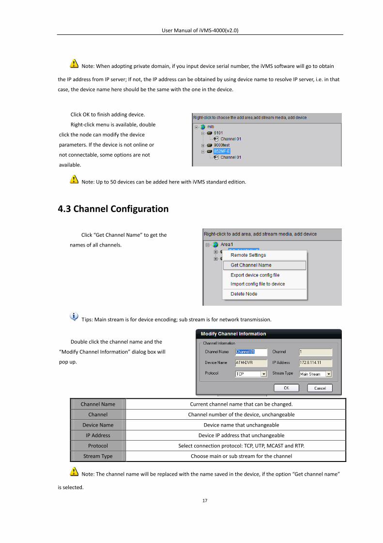
4.3 Channel Configuration
Tips: Main stream is for device encoding; sub stream is for network transmission.
Channel Name Current channel name that can be changed.
Channel Channel number of the device, unchangeable
Device Name Device name that unchangeable
IP Address Device IP address that unchangeable
Protocol Select connection protocol: TCP, UTP, MCAST and RTP.
Stream Type Choose main or sub stream for the channel
Note: The channel name will be replaced with the name saved in the device, if the option “Get channel name”
is selected.
Click OK to finish adding device.
Right-click menu is available, double
click the node can modify the device
parameters. If the device is not online or
not connectable, some options are not
available.
Click “Get Channel Name” to get the
names of all channels.
Double click the channel name and the
“Modify Channel Information” dialog box will
pop up.
User Manual of iVMS-4000(v2.0)
18
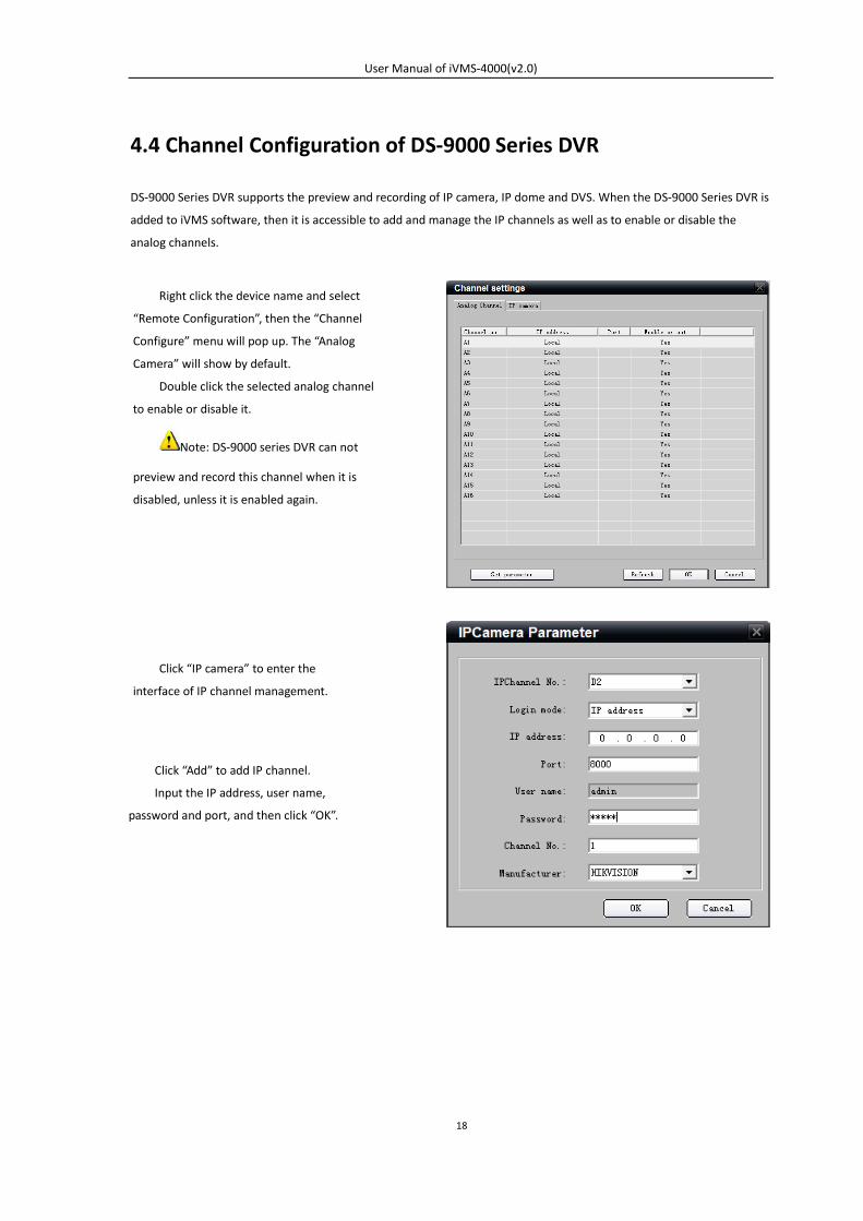
4.4 Channel Configuration of DS-9000 Series DVR
DS-9000 Series DVR supports the preview and recording of IP camera, IP dome and DVS. When the DS-9000 Series DVR is
added to iVMS software, then it is accessible to add and manage the IP channels as well as to enable or disable the
analog channels.
Right click the device name and select
“Remote Configuration”, then the “Channel
Configure” menu will pop up. The “Analog
Camera” will show by default.
Double click the selected analog channel
to enable or disable it.
Note: DS-9000 series DVR can not
preview and record this channel when it is
disabled, unless it is enabled again.
Click “IP camera” to enter the
interface of IP channel management.
Click “Add” to add IP channel.
Input the IP address, user name,
password and port, and then click “OK”.
User Manual of iVMS-4000(v2.0)
19
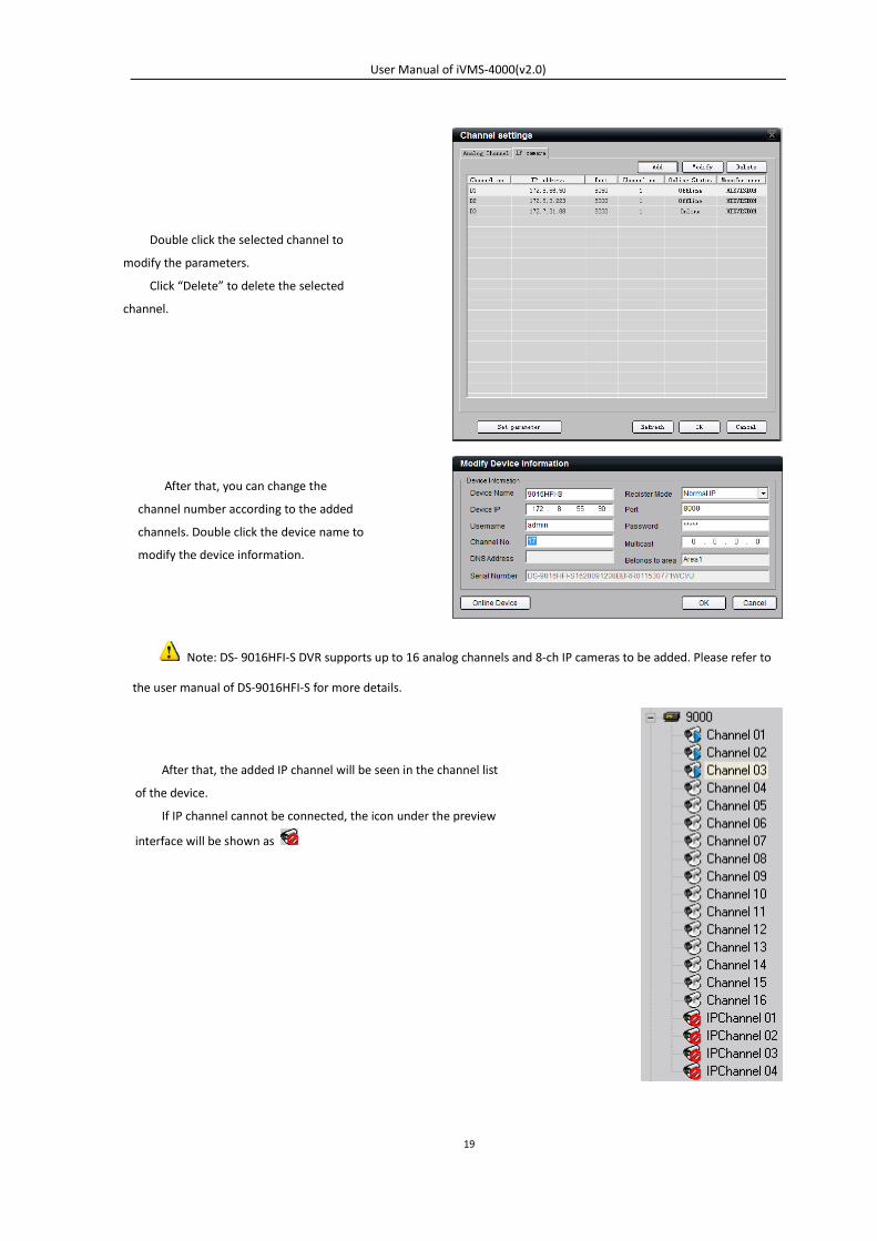
Note: DS- 9016HFI-S DVR supports up to 16 analog channels and 8-ch IP cameras to be added. Please refer to
the user manual of DS-9016HFI-S for more details.
Double click the selected channel to
modify the parameters.
Click “Delete” to delete the selected
channel.
After that, you can change the
channel number according to the added
channels. Double click the device name to
modify the device information.
After that, the added IP channel will be seen in the channel list
of the device.
If IP channel cannot be connected, the icon under the preview
interface will be shown as
User Manual of iVMS-4000(v2.0)
20
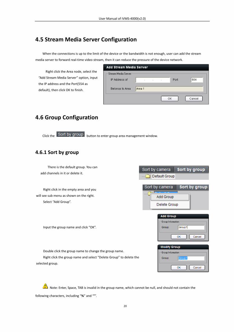
4.5 Stream Media Server Configuration
When the connections is up to the limit of the device or the bandwidth is not enough, user can add the stream
media server to forward real-time video stream, then it can reduce the pressure of the device network.
4.6 Group Configuration
Click the button to enter group area management window.
4.6.1 Sort by group
Note: Enter, Space, TAB is invalid in the group name, which cannot be null, and should not contain the
following characters, including “%” and “’”.
Right click in the empty area and you
will see sub menu as shown on the right.
Select “Add Group”.
Input the group name and click “OK”.
Double click the group name to change the group name.
Right click the group name and select “Delete Group” to delete the
selected group.
There is the default group. You can
add channels in it or delete it.
Right click the Area node, select the
“Add Stream Media Server” option, input
the IP address and the Port(554 as
default), then click OK to finish.
User Manual of iVMS-4000(v2.0)
21
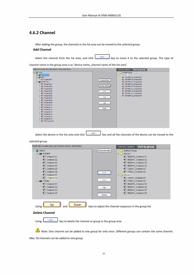
4.6.2 Channel
After adding the group, the channels in the list area can be moved to the selected group.
Add Channel
Select the channel from the list area, and click key to move it to the selected group. The type of
channel name in the group area is as “device name_channel name of the list area”.
Select the device in the list area and click key and all the channels of the device can be moved to the
selected group.
Using and keys to adjust the channel sequence in the group list.
Delete Channel
Using key to delete the channel or group in the group area
Note: One channel can be added to one group for only once. Different groups can contain the same channel.
Max. 50 channels can be added to one group.
User Manual of iVMS-4000(v2.0)
22
4.7 Sort by Camera Configuration
Click button to enter short key management window. Only the channels can be added to
the sort by camera area.
Select the channel from the list area, and click key and move it to the sort by camera area. The type
of channel name in the group area is as “device name_channel name of the list area”.
Select the device from the list area, and click key to add all the channels of the device to the sort by
camera area.
Use key to delete the channel in the sort by camera area.
Note: max. 256 channels can be added to sort by camera.
User Manual of iVMS-4000(v2.0)
23
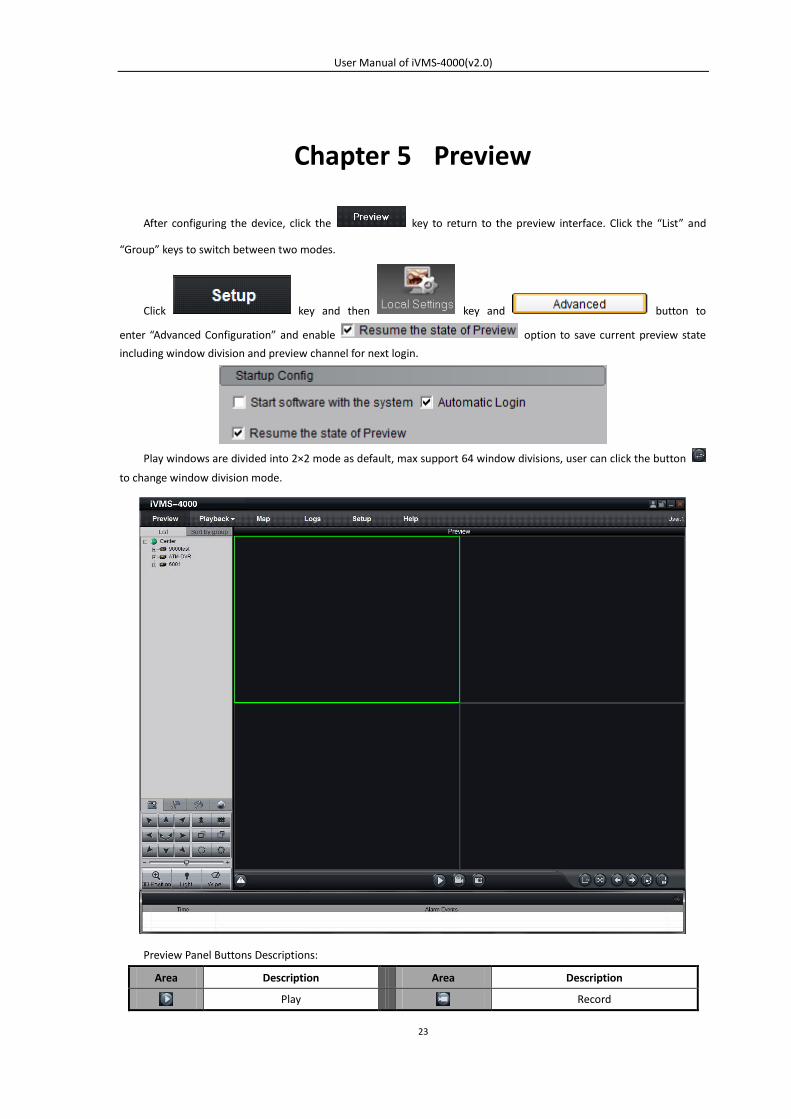
Chapter 5 Preview
After configuring the device, click the key to return to the preview interface. Click the “List” and
“Group” keys to switch between two modes.
Click key and then key and button to
enter “Advanced Configuration” and enable option to save current preview state
including window division and preview channel for next login.
Play windows are divided into 2×2 mode as default, max support 64 window divisions, user can click the button
to change window division mode.
Preview Panel Buttons Descriptions:
Area Description Area Description
Play Record
User Manual of iVMS-4000(v2.0)
24
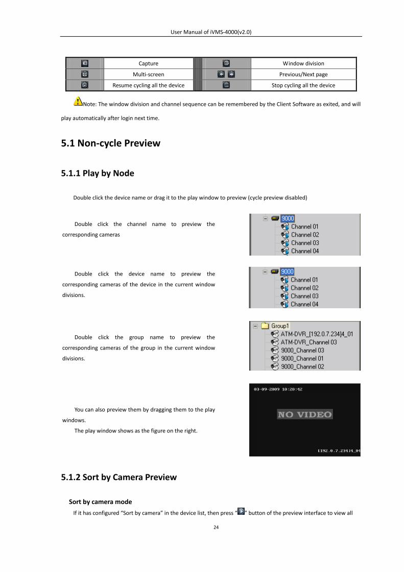
Capture Window division
Multi-screen Previous/Next page
Resume cycling all the device Stop cycling all the device
Note: The window division and channel sequence can be remembered by the Client Software as exited, and will
play automatically after login next time.
5.1 Non-cycle Preview
5.1.1 Play by Node
Double click the device name or drag it to the play window to preview (cycle preview disabled)
5.1.2 Sort by Camera Preview
Sort by camera mode
If it has configured “Sort by camera” in the device list, then press “ ” button of the preview interface to view all
Double click the channel name to preview the
corresponding cameras
Double click the device name to preview the
corresponding cameras of the device in the current window
divisions.
You can also preview them by dragging them to the play
windows.
The play window shows as the figure on the right.
Double click the group name to preview the
corresponding cameras of the group in the current window
divisions.
User Manual of iVMS-4000(v2.0)
25
the corresponding channels in the sort by camera area in the current window divisions. If the channel number is larger
than the window division number, user can click and to change the page to preview. Find more @ 4.7 Sort by
camera Configuration
Sort by group mode
Click the “Sort by group” to go to this mode. If the “Sort by group” has been configured, then press “ ” button of
the preview interface to view all the corresponding channels in the sort by camera area in the current window divisions.
If the channel number is larger than the window division number, user can click and to change the page to
preview. Find more @ 4.6.1 Sort by Group Configuration
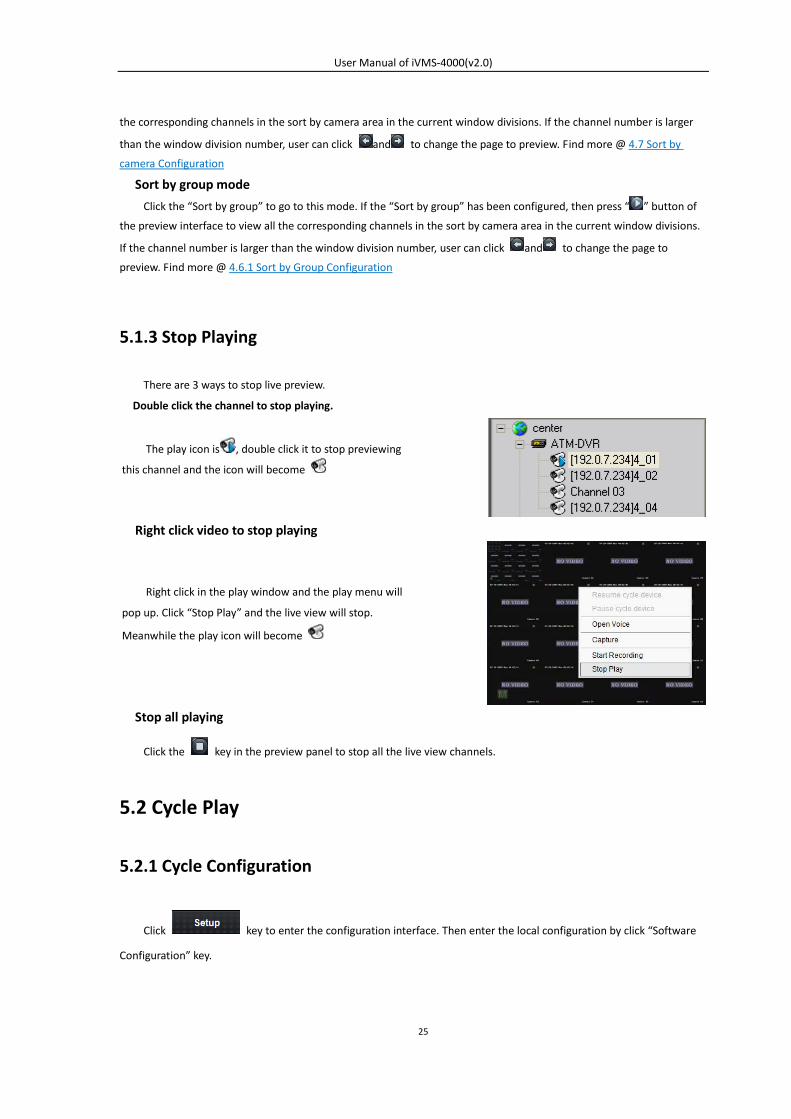
5.1.3 Stop Playing
There are 3 ways to stop live preview.
Double click the channel to stop playing.
Right click video to stop playing
Stop all playing
Click the key in the preview panel to stop all the live view channels.
5.2 Cycle Play
5.2.1 Cycle Configuration
Click key to enter the configuration interface. Then enter the local configuration by click “Software
Configuration” key.
The play icon is , double click it to stop previewing
this channel and the icon will become
Right click in the play window and the play menu will
pop up. Click “Stop Play” and the live view will stop.
Meanwhile the play icon will become
User Manual of iVMS-4000(v2.0)
26
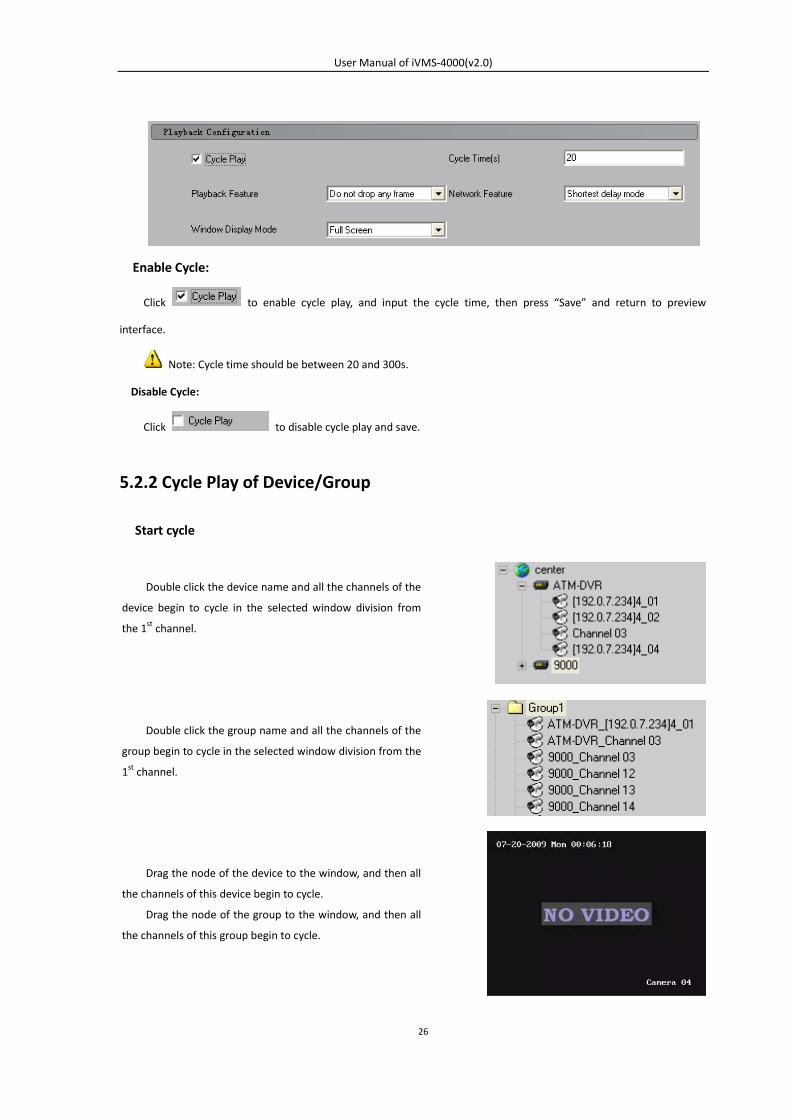
Enable Cycle:
Click to enable cycle play, and input the cycle time, then press “Save” and return to preview
interface.
Note: Cycle time should be between 20 and 300s.
Disable Cycle:
Click to disable cycle play and save.
5.2.2 Cycle Play of Device/Group
Start cycle
Double click the device name and all the channels of the
device begin to cycle in the selected window division from
the 1st channel.
Drag the node of the device to the window, and then all
the channels of this device begin to cycle.
Drag the node of the group to the window, and then all
the channels of this group begin to cycle.
Double click the group name and all the channels of the
group begin to cycle in the selected window division from the
1st channel.
User Manual of iVMS-4000(v2.0)
27
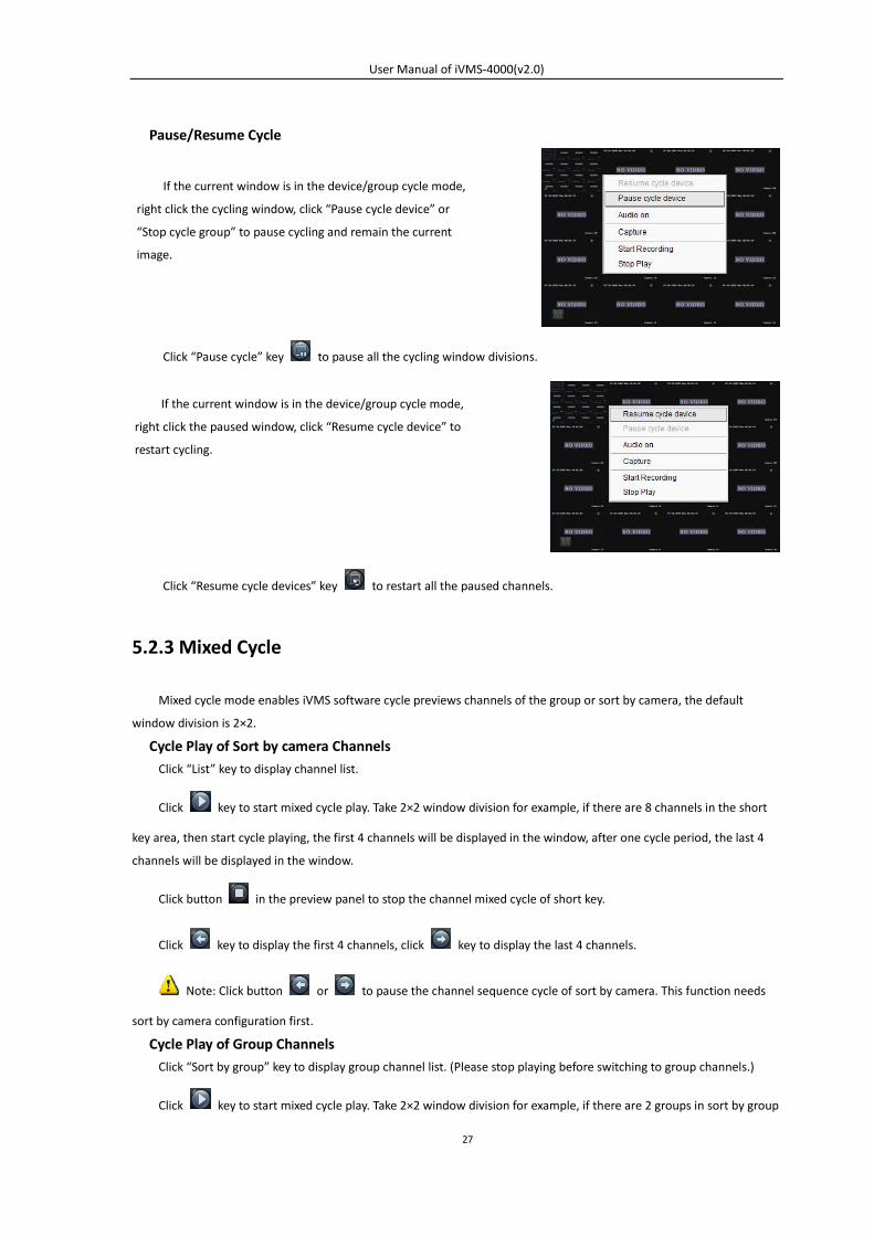
Pause/Resume Cycle
Click “Pause cycle” key to pause all the cycling window divisions.
Click “Resume cycle devices” key to restart all the paused channels.
5.2.3 Mixed Cycle
Mixed cycle mode enables iVMS software cycle previews channels of the group or sort by camera, the default
window division is 2×2.
Cycle Play of Sort by camera Channels Click “List” key to display channel list.
Click key to start mixed cycle play. Take 2×2 window division for example, if there are 8 channels in the short
key area, then start cycle playing, the first 4 channels will be displayed in the window, after one cycle period, the last 4
channels will be displayed in the window.
Click button in the preview panel to stop the channel mixed cycle of short key.
Click key to display the first 4 channels, click key to display the last 4 channels.
Note: Click button or to pause the channel sequence cycle of sort by camera. This function needs
sort by camera configuration first.
Cycle Play of Group Channels Click “Sort by group” key to display group channel list. (Please stop playing before switching to group channels.)
Click key to start mixed cycle play. Take 2×2 window division for example, if there are 2 groups in sort by group
If the current window is in the device/group cycle mode,
right click the cycling window, click “Pause cycle device” or
“Stop cycle group” to pause cycling and remain the current
image.
If the current window is in the device/group cycle mode,
right click the paused window, click “Resume cycle device” to
restart cycling.
User Manual of iVMS-4000(v2.0)
28
area, each of them has 4 channels, then start cycle playing, 4 channels of the first group will be displayed in the window,
after one cycle period, 4 channels of the second group will be displayed in the window.
Click key to display the first 4 channels, click key to display the last 4 channels.
Note: Click button or to pause the channel sequence cycle of sort by group. This function needs
sort by group configuration first.
5.3 Preview Control
Full Screen:
When previewing, click key to preview in full screen, to exit click key.
Enlarge: When in the multi-screen preview mode, double click the selected image to enlarge it, double click again to resume.
If user is previewing the zero-channel, double click it first time, it will enlarge the zero-channel, double click on
window division in the zero-channel video, it will enlarge that channel to fill the zero-channel video. Double click it the
third time, it will only change the zero-channel form single to multi display.
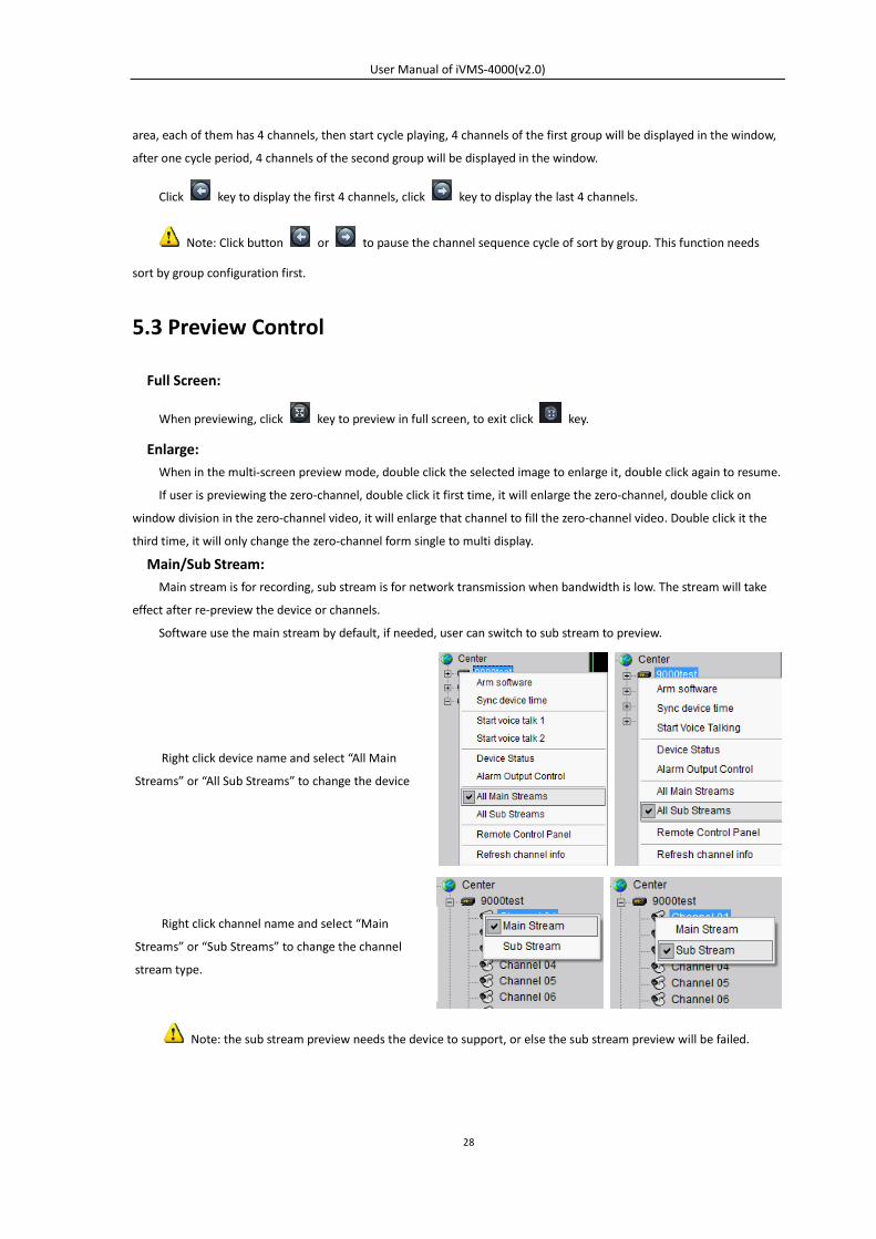
Main/Sub Stream: Main stream is for recording, sub stream is for network transmission when bandwidth is low. The stream will take
effect after re-preview the device or channels.
Software use the main stream by default, if needed, user can switch to sub stream to preview.
Note: the sub stream preview needs the device to support, or else the sub stream preview will be failed.
Right click device name and select “All Main
Streams” or “All Sub Streams” to change the device
Right click channel name and select “Main
Streams” or “Sub Streams” to change the channel
stream type.
User Manual of iVMS-4000(v2.0)
29
Voice Control
Note: The software only can open voice of one window at the same time. If the voice of the next window is opened
then the voice of the previous will be closed automatically.
5.4 Two Screen Preview
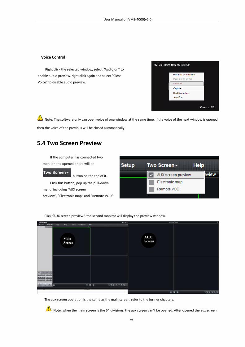
Click “AUX screen preview”, the second monitor will display the preview window.
The aux screen operation is the same as the main screen, refer to the former chapters.
Note: when the main screen is the 64 divisions, the aux screen can’t be opened. After opened the aux screen,
Right click the selected window, select “Audio on” to
enable audio preview, right click again and select “Close
Voice” to disable audio preview.
If the computer has connected two
monitor and opened, there will be
button on the top of it.
Click this button, pop up the pull-down
menu, including ”AUX screen
preview”, ”Electronic map” and ”Remote VOD”
User Manual of iVMS-4000(v2.0)
30
they both max support 32 window divisions.
5.5 Recording & Capture
Recording and capture is only available in the live view mode.
Note: If the channel is in the recording mode, click “Stop” button to stop recording, and the preview, cycle play
are stopped as well.
5.5.1 Recording
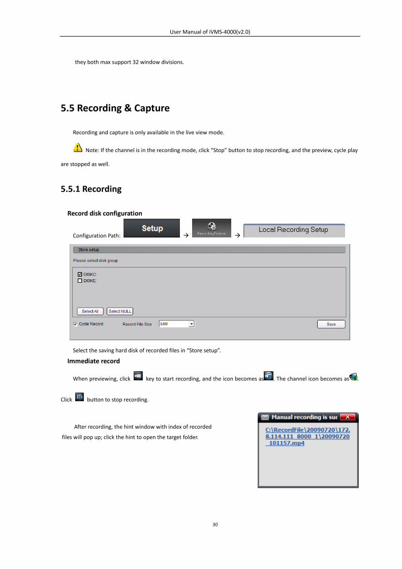
Record disk configuration
Configuration Path:
Select the saving hard disk of recorded files in “Store setup”.
Immediate record
When previewing, click key to start recording, and the icon becomes as . The channel icon becomes as .
Click button to stop recording.
After recording, the hint window with index of recorded
files will pop up; click the hint to open the target folder.
User Manual of iVMS-4000(v2.0)
31
5.5.2 Capture
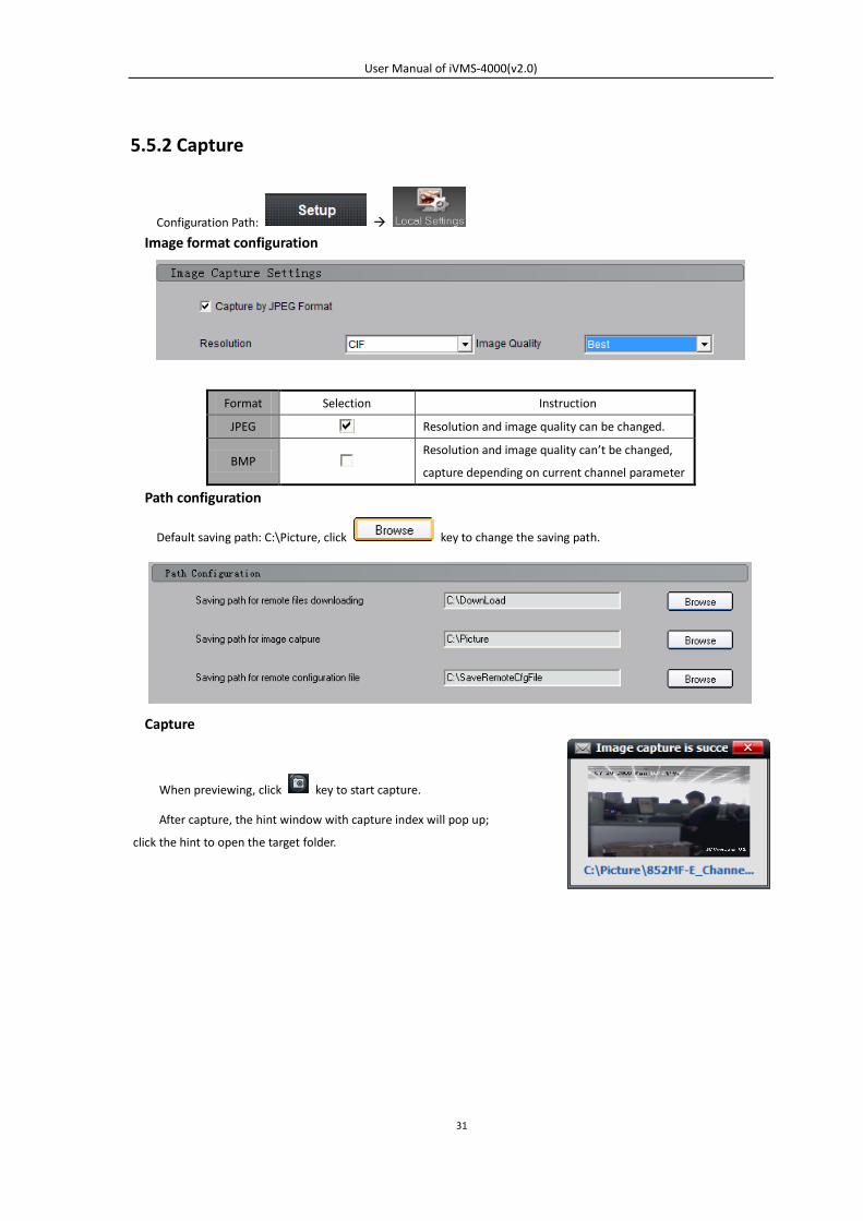
Configuration Path:
Image format configuration
Format Selection Instruction
JPEG Resolution and image quality can be changed.
BMP Resolution and image quality can’t be changed,
capture depending on current channel parameter
Path configuration
Default saving path: C:\Picture, click key to change the saving path.
Capture
When previewing, click key to start capture.
After capture, the hint window with capture index will pop up;
click the hint to open the target folder.
User Manual of iVMS-4000(v2.0)
32
5.6 Hardware Decode
If there is video/audio decoding card installed in the computer, then this function can be available.
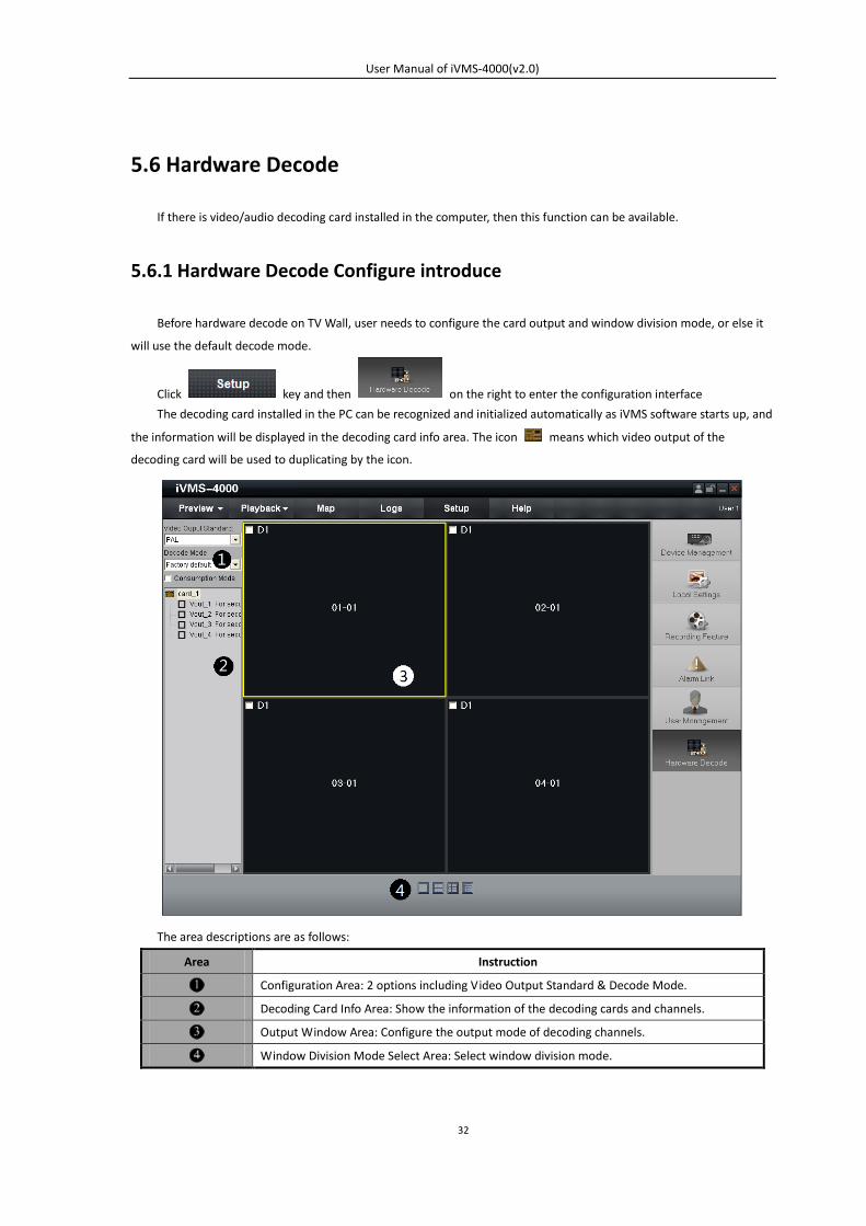
5.6.1 Hardware Decode Configure introduce
Before hardware decode on TV Wall, user needs to configure the card output and window division mode, or else it
will use the default decode mode.
Click key and then on the right to enter the configuration interface
The decoding card installed in the PC can be recognized and initialized automatically as iVMS software starts up, and
the information will be displayed in the decoding card info area. The icon means which video output of the
decoding card will be used to duplicating by the icon.
The area descriptions are as follows:
Area Instruction
Configuration Area: 2 options including Video Output Standard & Decode Mode.
Decoding Card Info Area: Show the information of the decoding cards and channels.
Output Window Area: Configure the output mode of decoding channels.
Window Division Mode Select Area: Select window division mode.
User Manual of iVMS-4000(v2.0)
33
5.6.2 Hardware Decode Mode Configuration
Decode Mode Descriptions
Factory Default Each 4002MDI card decodes 2 channels; each 4004MDI card decodes 4 channels
and so on. Support decoding and cycling play.
TV wall on & Preview on The images from the play window of iVMS software and TV wall are decoded by
MDI card, which needs to configure in the hardware decode configuration.
TV wall on & Preview off The images from the TV wall are decoded by MDI card; the images from the play
window of iVMS software are decoded by CPU.
If the resolution of all the images is CIF, then the max decoding channel number is: 4 channels for each 4002MDI
card; 8 channels for 4004MDI card.
If the resolution of all the images is D1, then the max decoding channel number is: 2 channels for each 4002MDI
card; 4 channels for 4004MDI card.
Tips: don’t output more than 4-ch CIF or 2-ch D1 from the 4002MDI card, don’t output more than 8-ch CIF or
4-ch D1 from the 4004MDI card.
Enable special decode mode, and in ”Setup” ”Alarm link” set the alarm link type “Pop up image when alarm
occurs”, the iVMS software will output the video through 4000MDI card on TV wall when there is alarm.
Note: The video output mode of images from device and TV wall need to be the same standard, or else the
image will become abnormal.
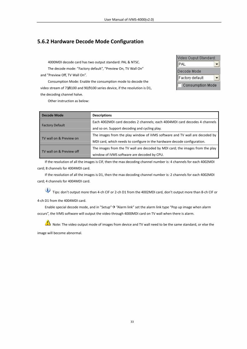
4000MDI decode card has two output standard: PAL & NTSC.
The decode mode: ”Factory default”, ”Preview On, TV Wall On”
and ”Preview Off, TV Wall On”.
Consumption Mode: Enable the consumption mode to decode the
video stream of 73/8100 and 90/9100 series device, if the resolution is D1,
the decoding channel halve.
Other instruction as below:
User Manual of iVMS-4000(v2.0)
34
5.6.3 Hardware Decode Output Window Configuration
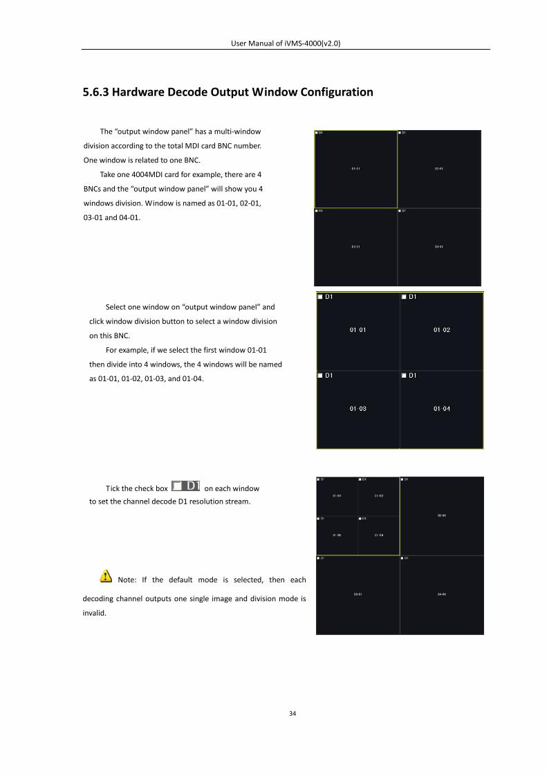
Note: If the default mode is selected, then each
decoding channel outputs one single image and division mode is
invalid.
The “output window panel” has a multi-window
division according to the total MDI card BNC number.
One window is related to one BNC.
Take one 4004MDI card for example, there are 4
BNCs and the “output window panel” will show you 4
windows division. Window is named as 01-01, 02-01,
03-01 and 04-01.
Select one window on “output window panel” and
click window division button to select a window division
on this BNC.
For example, if we select the first window 01-01
then divide into 4 windows, the 4 windows will be named
as 01-01, 01-02, 01-03, and 01-04.
Tick the check box on each window
to set the channel decode D1 resolution stream.
User Manual of iVMS-4000(v2.0)
35
5.6.4 Hardware Decode Preview
The basic operations of hardware preview are the same with software decode, please refer to sections 5.1-5.5 for
more details.
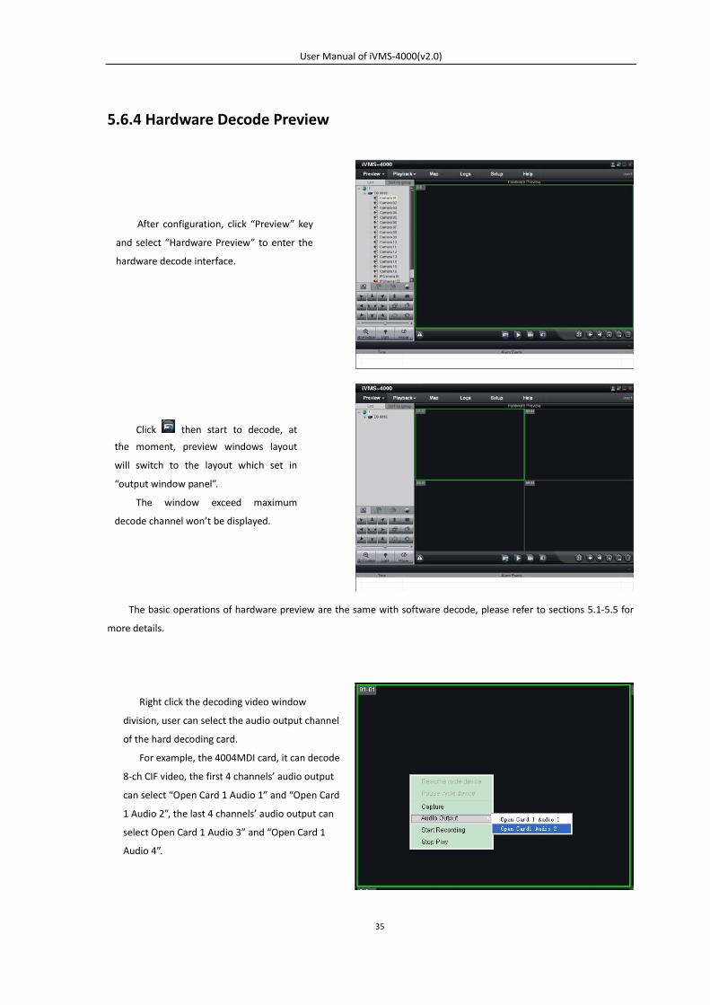
After configuration, click “Preview” key
and select “Hardware Preview” to enter the
hardware decode interface.
Click then start to decode, at
the moment, preview windows layout
will switch to the layout which set in
“output window panel”.
The window exceed maximum
decode channel won’t be displayed.
Right click the decoding video window
division, user can select the audio output channel
of the hard decoding card.
For example, the 4004MDI card, it can decode
8-ch CIF video, the first 4 channels’ audio output
can select “Open Card 1 Audio 1” and “Open Card
1 Audio 2”, the last 4 channels’ audio output can
select Open Card 1 Audio 3” and “Open Card 1
Audio 4”.
User Manual of iVMS-4000(v2.0)
36
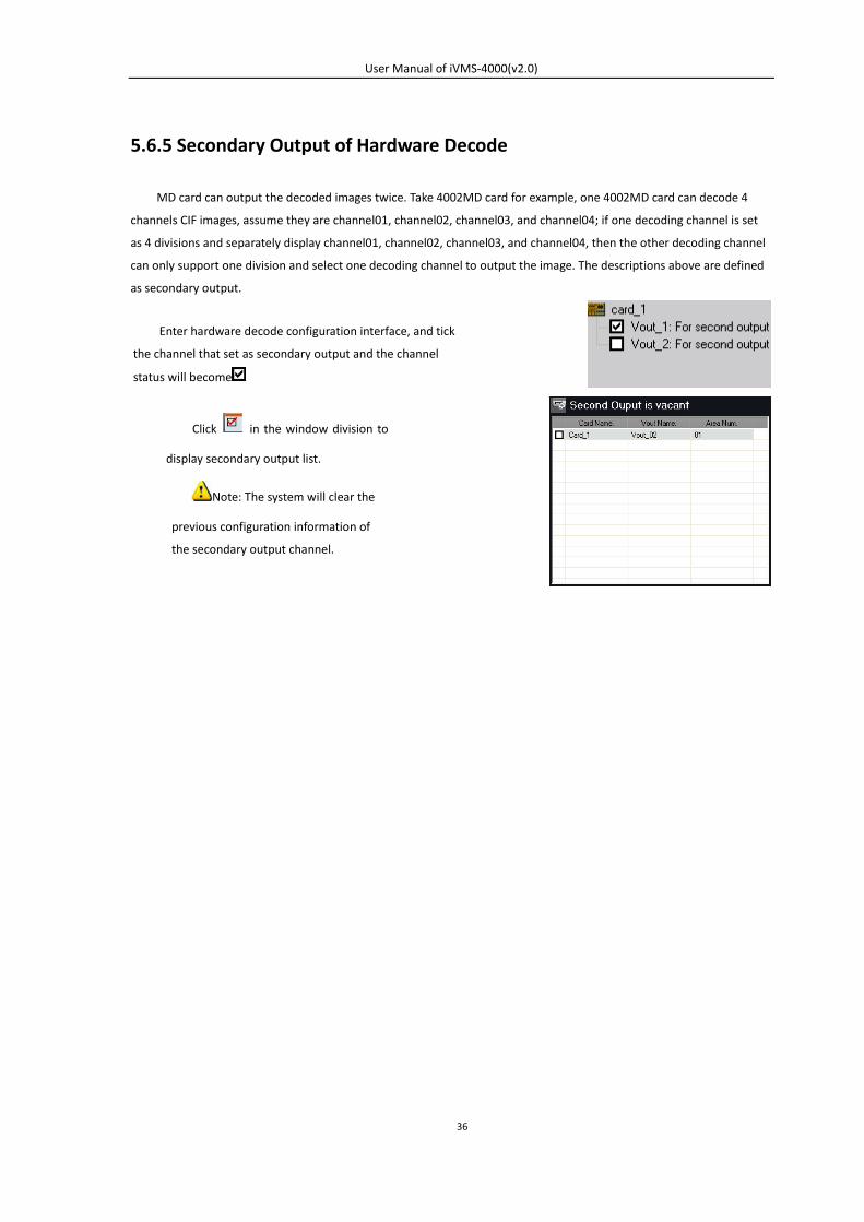
5.6.5 Secondary Output of Hardware Decode
MD card can output the decoded images twice. Take 4002MD card for example, one 4002MD card can decode 4
channels CIF images, assume they are channel01, channel02, channel03, and channel04; if one decoding channel is set
as 4 divisions and separately display channel01, channel02, channel03, and channel04, then the other decoding channel
can only support one division and select one decoding channel to output the image. The descriptions above are defined
as secondary output.
Enter hardware decode configuration interface, and tick
the channel that set as secondary output and the channel
status will become
Click in the window division to
display secondary output list.
Note: The system will clear the
previous configuration information of
the secondary output channel.
User Manual of iVMS-4000(v2.0)
37
5.7 Others
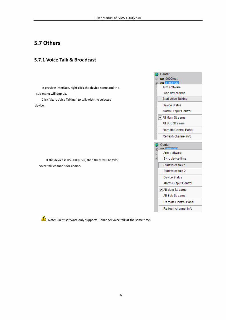
5.7.1 Voice Talk & Broadcast
Note: Client software only supports 1-channel voice talk at the same time.
In preview interface, right click the device name and the
sub menu will pop up.
Click “Start Voice Talking” to talk with the selected
device.
If the device is DS-9000 DVR, then there will be two
voice talk channels for choice.
User Manual of iVMS-4000(v2.0)
38
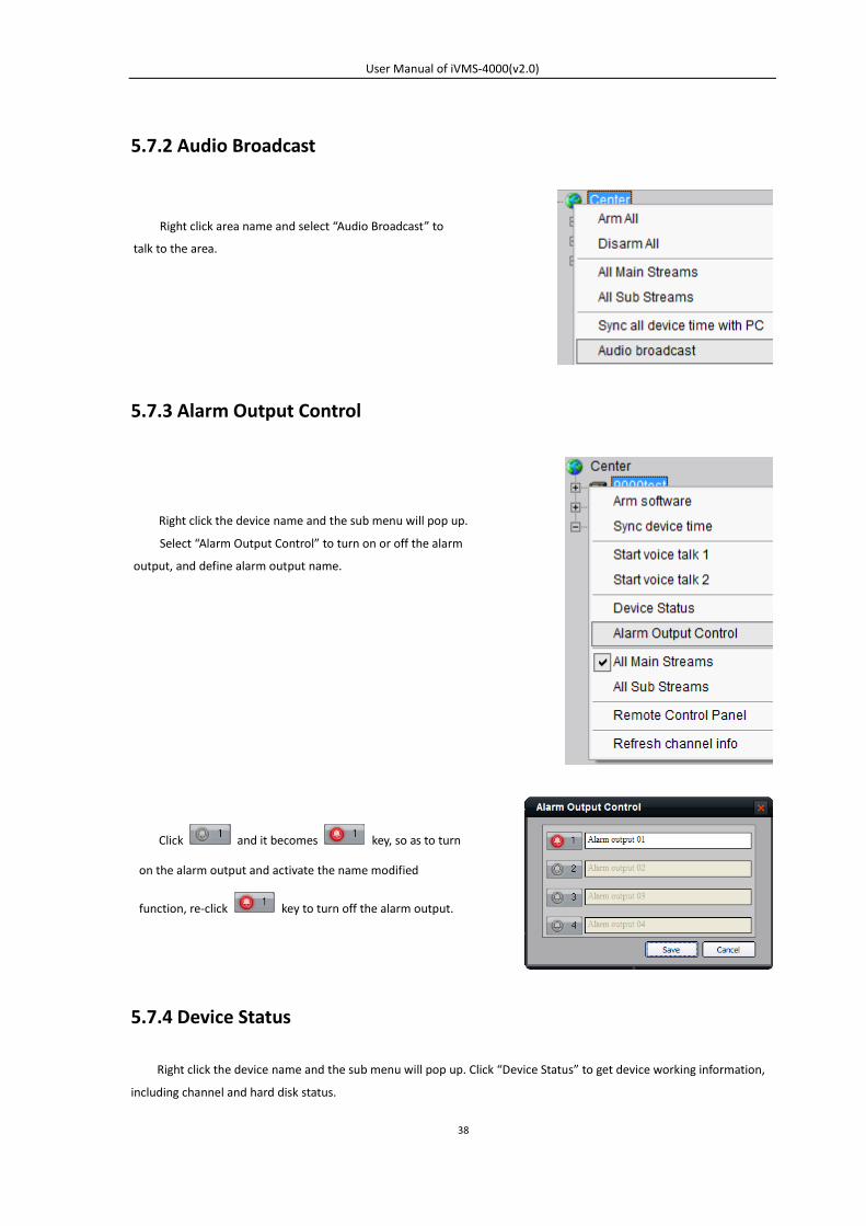
5.7.2 Audio Broadcast
5.7.3 Alarm Output Control
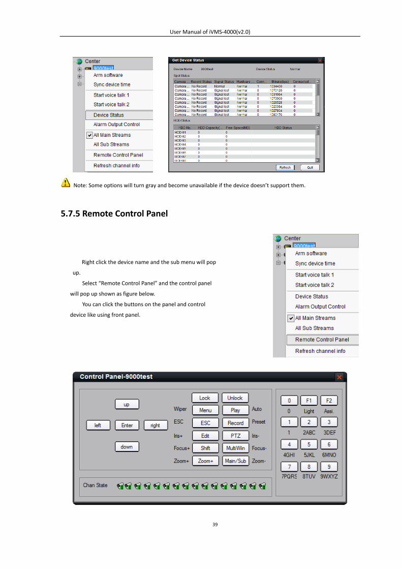
5.7.4 Device Status
Right click the device name and the sub menu will pop up. Click “Device Status” to get device working information,
including channel and hard disk status.
Right click area name and select “Audio Broadcast” to
talk to the area.
Right click the device name and the sub menu will pop up.
Select “Alarm Output Control” to turn on or off the alarm
output, and define alarm output name.
Click and it becomes key, so as to turn
on the alarm output and activate the name modified
function, re-click key to turn off the alarm output.
User Manual of iVMS-4000(v2.0)
39
Note: Some options will turn gray and become unavailable if the device doesn’t support them.
5.7.5 Remote Control Panel
Right click the device name and the sub menu will pop
up.
Select “Remote Control Panel” and the control panel
will pop up shown as figure below.
You can click the buttons on the panel and control
device like using front panel.
User Manual of iVMS-4000(v2.0)
40
Chapter 6 PTZ Control
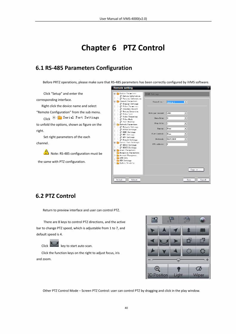
6.1 RS-485 Parameters Configuration
Before PRTZ operations, please make sure that RS-485 parameters has been correctly configured by iVMS software.
6.2 PTZ Control
Return to preview interface and user can control PTZ.
Other PTZ Control Mode – Screen PTZ Control: user can control PTZ by dragging and click in the play window.
There are 8 keys to control PTZ directions, and the active
bar to change PTZ speed, which is adjustable from 1 to 7, and
default speed is 4.
Click key to start auto scan.
Click the function keys on the right to adjust focus, iris
and zoom.
Click “Setup” and enter the
corresponding interface.
Right click the device name and select
“Remote Configuration” from the sub menu.
Click
to unfold the options, shown as figure on the
right.
Set right parameters of the each
channel.
Note: RS-485 configuration must be
the same with PTZ configuration.
User Manual of iVMS-4000(v2.0)
41
6.3 Partial Zoom
Click “Partial Zoom” to zoom in or out, the mouse icon will become as , press the left key of the mouse and drag
an area you want to zoom.
Drag from up left to down right to zoom in; drag from down right to up left to zoom out.
Note: This function is only available as HIKVISION protocol is selected for PTZ.
6.4 Preset
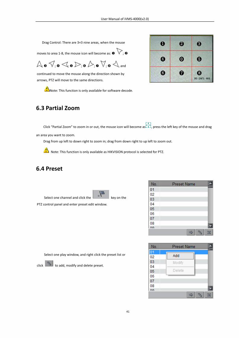
Drag Control: There are 3×3 nine areas, when the mouse
moves to area 1-8, the mouse icon will become as: ;
; ; ; ; ; ; , and
continued to move the mouse along the direction shown by
arrows, PTZ will move to the same directions.
Note: This function is only available for software decode.
Select one channel and click the key on the
PTZ control panel and enter preset edit window.
Select one play window, and right click the preset list or
click to add, modify and delete preset.
User Manual of iVMS-4000(v2.0)
42
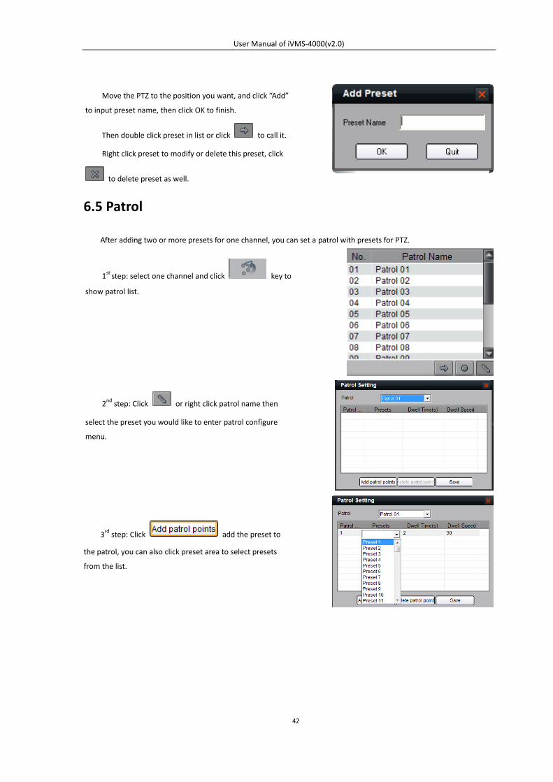
6.5 Patrol
After adding two or more presets for one channel, you can set a patrol with presets for PTZ.
Move the PTZ to the position you want, and click “Add”
to input preset name, then click OK to finish.
Then double click preset in list or click to call it.
Right click preset to modify or delete this preset, click
to delete preset as well.
1st step: select one channel and click key to
show patrol list.
2nd step: Click or right click patrol name then
select the preset you would like to enter patrol configure
menu.
3rd step: Click add the preset to
the patrol, you can also click preset area to select presets
from the list.
User Manual of iVMS-4000(v2.0)
43
After configuration, you can choose the patrol from the list , and call/stop them by
clicking and keys.
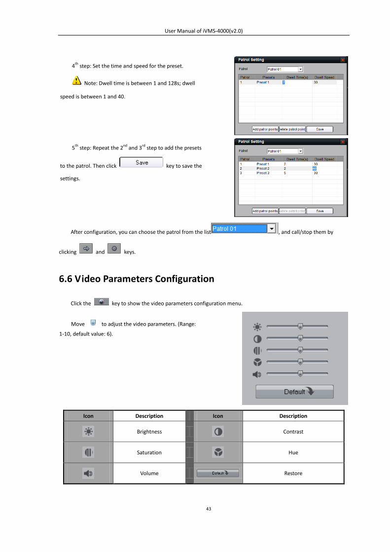
6.6 Video Parameters Configuration
Click the key to show the video parameters configuration menu.
Icon Description Icon Description
Brightness
Contrast
Saturation
Hue
Volume Restore
4th step: Set the time and speed for the preset.
Note: Dwell time is between 1 and 128s; dwell
speed is between 1 and 40.
5th step: Repeat the 2nd and 3rd step to add the presets
to the patrol. Then click key to save the
settings.
Move to adjust the video parameters. (Range:
1-10, default value: 6).
User Manual of iVMS-4000(v2.0)
44
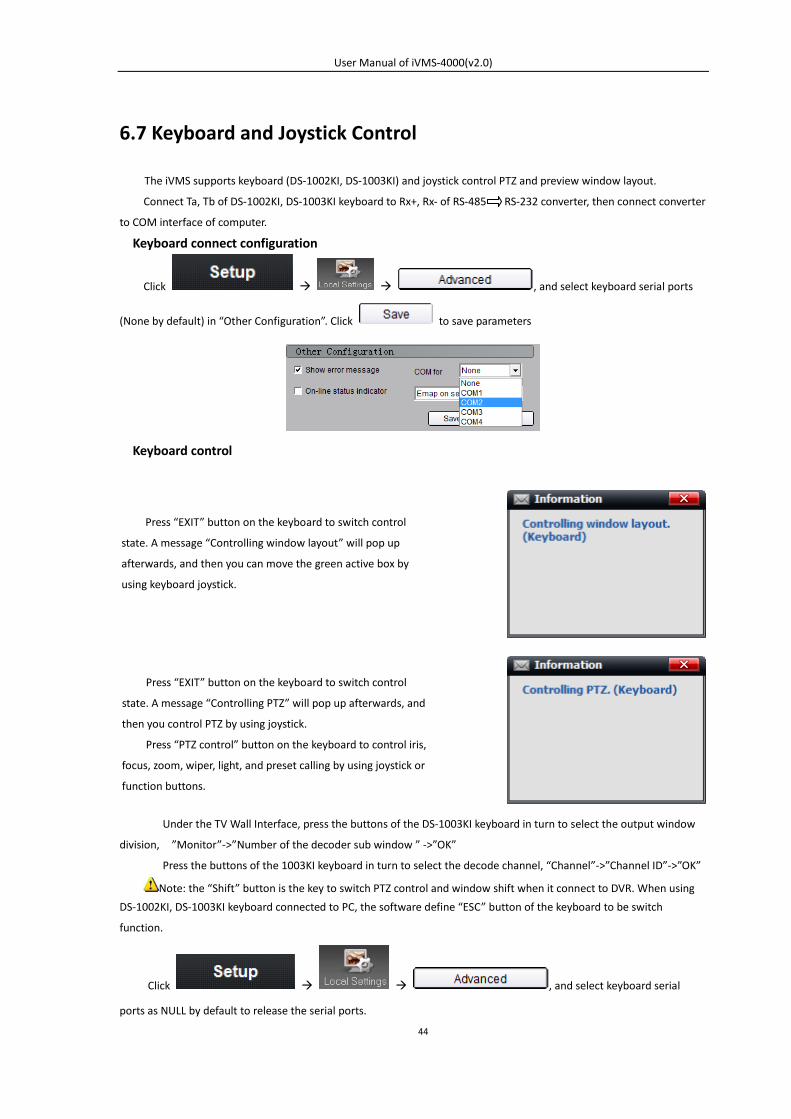
6.7 Keyboard and Joystick Control
The iVMS supports keyboard (DS-1002KI, DS-1003KI) and joystick control PTZ and preview window layout.
Connect Ta, Tb of DS-1002KI, DS-1003KI keyboard to Rx+, Rx- of RS-485 RS-232 converter, then connect converter
to COM interface of computer.
Keyboard connect configuration
Click , and select keyboard serial ports
(None by default) in “Other Configuration”. Click to save parameters
Keyboard control
Under the TV Wall Interface, press the buttons of the DS-1003KI keyboard in turn to select the output window
division, ”Monitor”->”Number of the decoder sub window ” ->”OK”
Press the buttons of the 1003KI keyboard in turn to select the decode channel, “Channel”->”Channel ID”->”OK”
Note: the “Shift” button is the key to switch PTZ control and window shift when it connect to DVR. When using
DS-1002KI, DS-1003KI keyboard connected to PC, the software define “ESC” button of the keyboard to be switch
function.
Click , and select keyboard serial
ports as NULL by default to release the serial ports.
Press “EXIT” button on the keyboard to switch control
state. A message “Controlling window layout” will pop up
afterwards, and then you can move the green active box by
using keyboard joystick.
Press “EXIT” button on the keyboard to switch control
state. A message “Controlling PTZ” will pop up afterwards, and
then you control PTZ by using joystick.
Press “PTZ control” button on the keyboard to control iris,
focus, zoom, wiper, light, and preset calling by using joystick or
function buttons.
User Manual of iVMS-4000(v2.0)
45
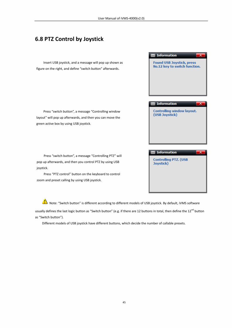
6.8 PTZ Control by Joystick
Note: “Switch button” is different according to different models of USB joystick. By default, iVMS software
usually defines the last logic button as “Switch button” (e.g. if there are 12 buttons in total, then define the 12nd button
as “Switch button”).
Different models of USB joystick have different buttons, which decide the number of callable presets.
Insert USB joystick, and a message will pop up shown as
figure on the right, and define “switch button” afterwards.
Press “switch button”, a message “Controlling window
layout” will pop up afterwards, and then you can move the
green active box by using USB joystick.
Press “switch button”, a message “Controlling PTZ” will
pop up afterwards, and then you control PTZ by using USB
joystick.
Press “PTZ control” button on the keyboard to control
zoom and preset calling by using USB joystick.
User Manual of iVMS-4000(v2.0)
46
Chapter 7 Recording
7.1 Local Recording
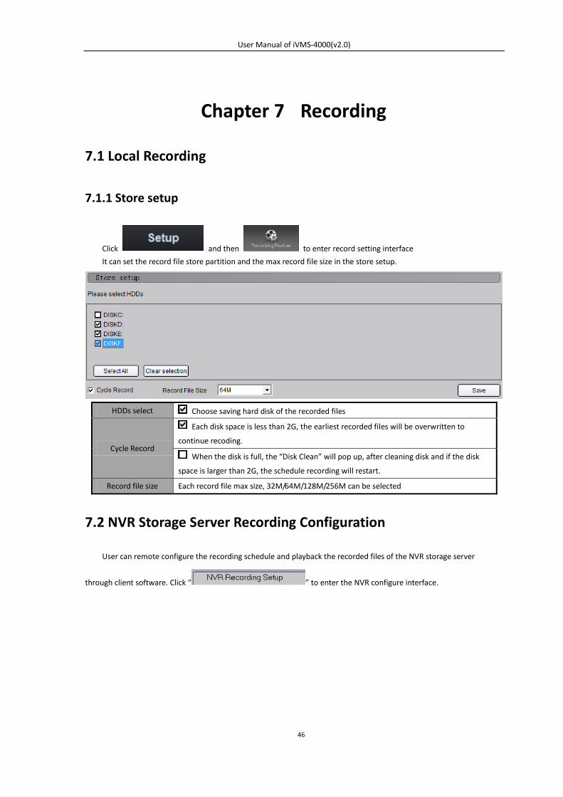
7.1.1 Store setup
Click and then to enter record setting interface
It can set the record file store partition and the max record file size in the store setup.
HDDs select Choose saving hard disk of the recorded files
Cycle Record
Each disk space is less than 2G, the earliest recorded files will be overwritten to
continue recoding.
When the disk is full, the “Disk Clean” will pop up, after cleaning disk and if the disk
space is larger than 2G, the schedule recording will restart.
Record file size Each record file max size, 32M/64M/128M/256M can be selected
7.2 NVR Storage Server Recording Configuration
User can remote configure the recording schedule and playback the recorded files of the NVR storage server
through client software. Click “ ” to enter the NVR configure interface.
User Manual of iVMS-4000(v2.0)
47
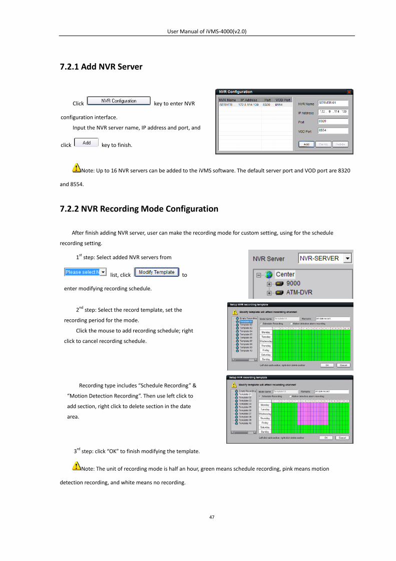
7.2.1 Add NVR Server
Note: Up to 16 NVR servers can be added to the iVMS software. The default server port and VOD port are 8320
and 8554.
7.2.2 NVR Recording Mode Configuration
After finish adding NVR server, user can make the recording mode for custom setting, using for the schedule
recording setting.
3rd step: click “OK” to finish modifying the template.
Note: The unit of recording mode is half an hour, green means schedule recording, pink means motion
detection recording, and white means no recording.
1st step: Select added NVR servers from
list, click to
enter modifying recording schedule.
Click key to enter NVR
configuration interface.
Input the NVR server name, IP address and port, and
click key to finish.
2nd step: Select the record template, set the
recording period for the mode.
Click the mouse to add recording schedule; right
click to cancel recording schedule.
Recording type includes “Schedule Recording” &
“Motion Detection Recording”. Then use left click to
add section, right click to delete section in the date
area.
User Manual of iVMS-4000(v2.0)
48
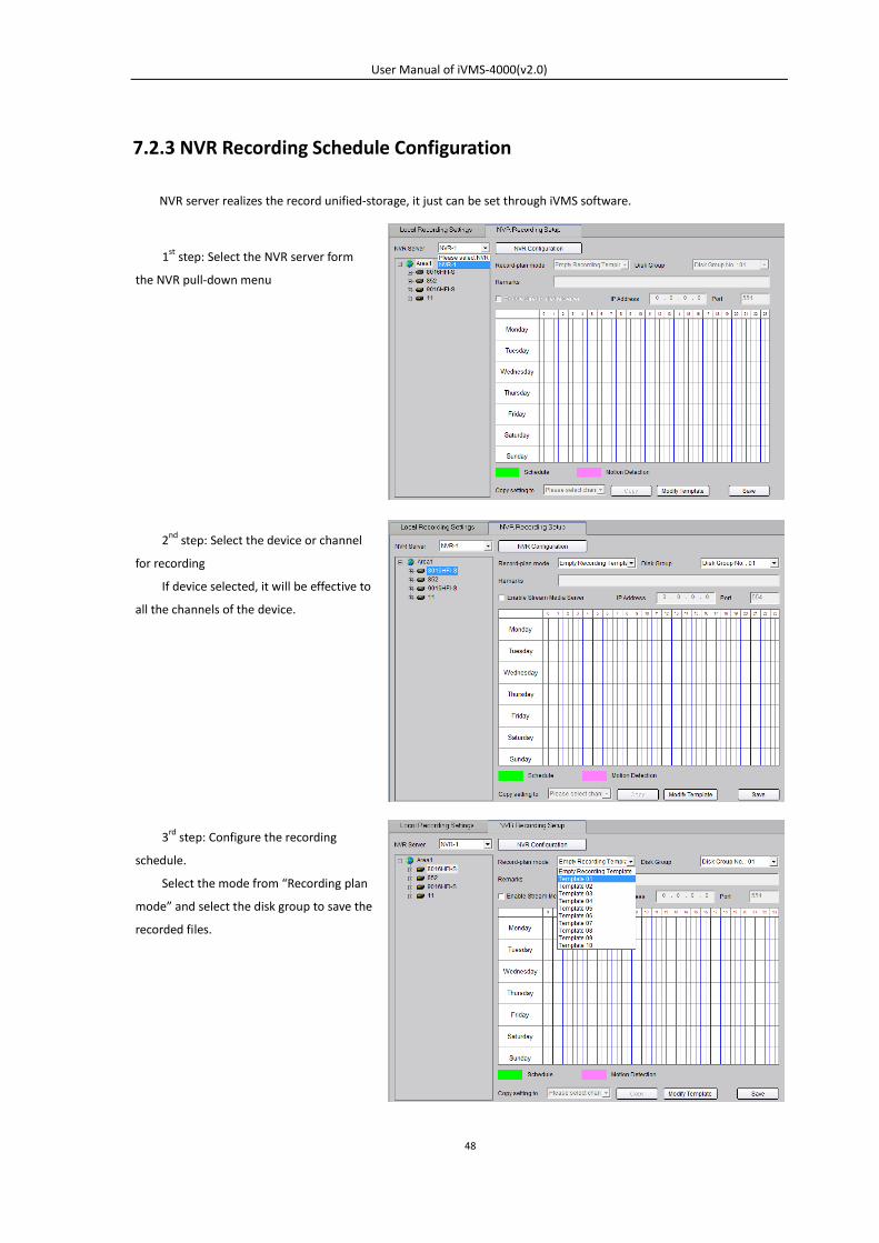
7.2.3 NVR Recording Schedule Configuration
NVR server realizes the record unified-storage, it just can be set through iVMS software.
1st step: Select the NVR server form
the NVR pull-down menu
2nd step: Select the device or channel
for recording
If device selected, it will be effective to
all the channels of the device.
3rd step: Configure the recording
schedule.
Select the mode from “Recording plan
mode” and select the disk group to save the
recorded files.

User Manual of iVMS-4000(v2.0)
49
If necessary, enable stream media server and input the IP address and port.
Click to finish the NVR server schedule recording configuration.
User Manual of iVMS-4000(v2.0)
50
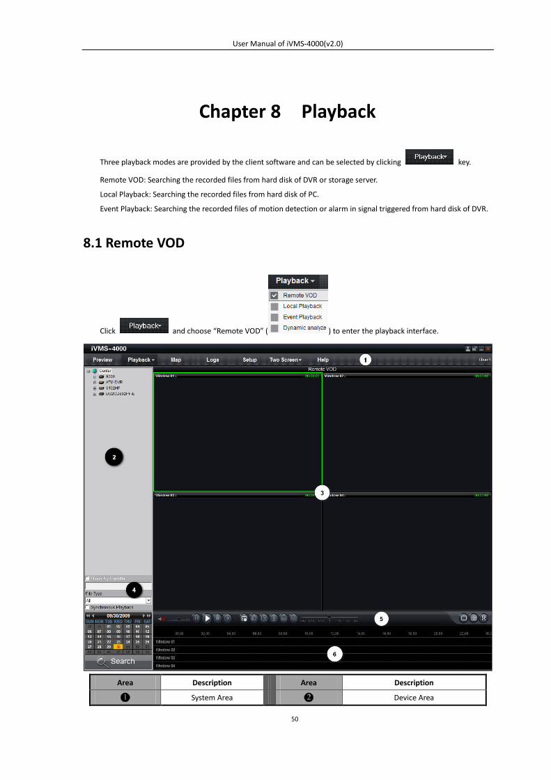
Chapter 8 Playback
Three playback modes are provided by the client software and can be selected by clicking key.
Remote VOD: Searching the recorded files from hard disk of DVR or storage server.
Local Playback: Searching the recorded files from hard disk of PC.
Event Playback: Searching the recorded files of motion detection or alarm in signal triggered from hard disk of DVR.
8.1 Remote VOD
Click and choose “Remote VOD” ( ) to enter the playback interface.
Area Description Area Description
System Area Device Area
User Manual of iVMS-4000(v2.0)
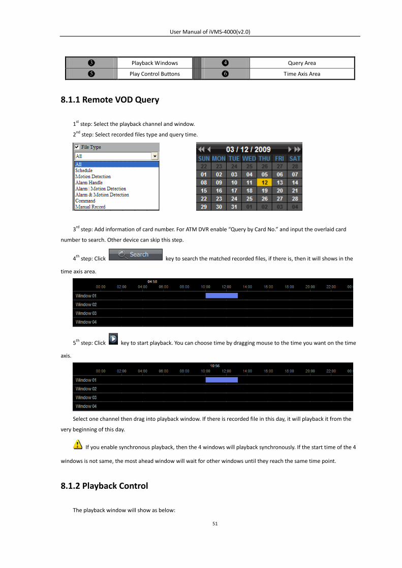
51
Playback Windows Query Area
Play Control Buttons Time Axis Area
8.1.1 Remote VOD Query
1st step: Select the playback channel and window.
2nd step: Select recorded files type and query time.
3rd step: Add information of card number. For ATM DVR enable “Query by Card No.” and input the overlaid card
number to search. Other device can skip this step.
4th step: Click key to search the matched recorded files, if there is, then it will shows in the
time axis area.
5th step: Click key to start playback. You can choose time by dragging mouse to the time you want on the time
axis.
Select one channel then drag into playback window. If there is recorded file in this day, it will playback it from the
very beginning of this day.
If you enable synchronous playback, then the 4 windows will playback synchronously. If the start time of the 4
windows is not same, the most ahead window will wait for other windows until they reach the same time point.
8.1.2 Playback Control
The playback window will show as below:
User Manual of iVMS-4000(v2.0)
52
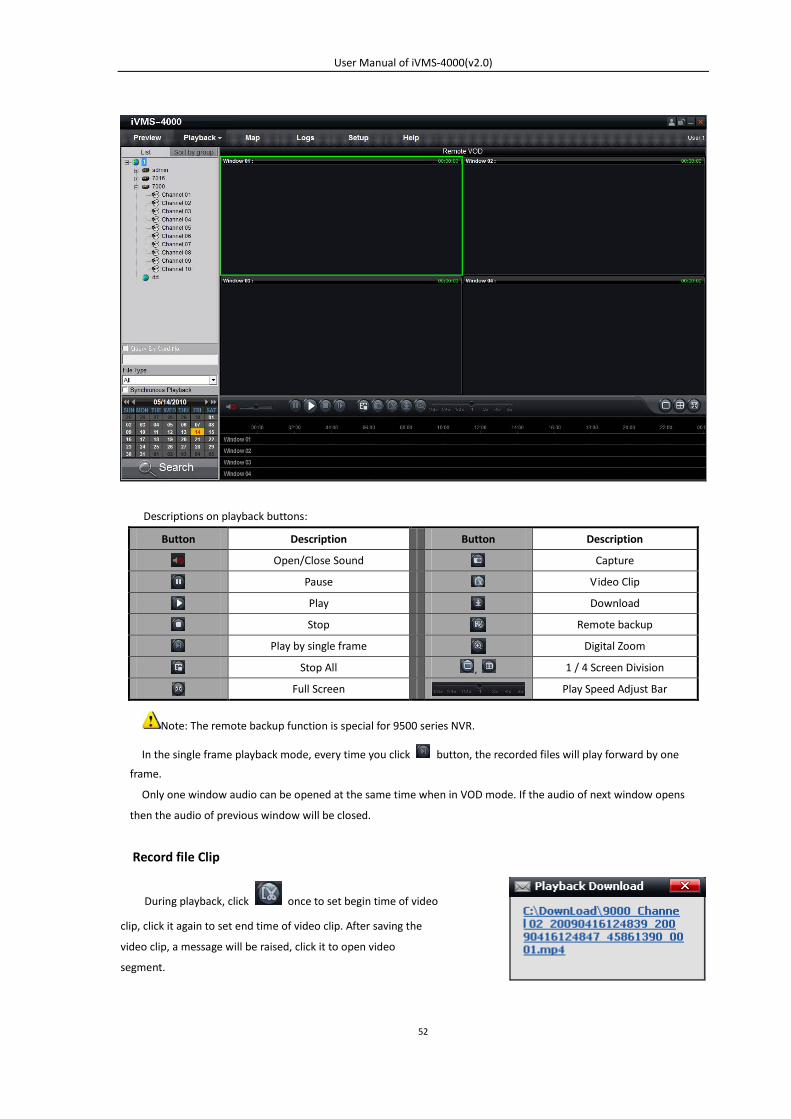
Descriptions on playback buttons:
Button Description Button Description
Open/Close Sound Capture
Pause Video Clip
Play Download
Stop Remote backup
Play by single frame Digital Zoom
Stop All , 1 / 4 Screen Division
Full Screen Play Speed Adjust Bar
Note: The remote backup function is special for 9500 series NVR.
In the single frame playback mode, every time you click button, the recorded files will play forward by one
frame.
Only one window audio can be opened at the same time when in VOD mode. If the audio of next window opens
then the audio of previous window will be closed.
Record file Clip
During playback, click once to set begin time of video
clip, click it again to set end time of video clip. After saving the
video clip, a message will be raised, click it to open video
segment.
User Manual of iVMS-4000(v2.0)
53
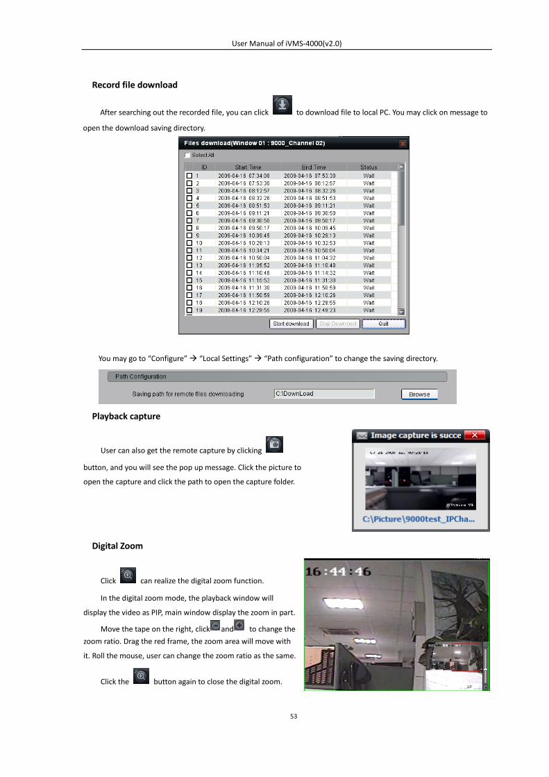
Record file download
After searching out the recorded file, you can click to download file to local PC. You may click on message to
open the download saving directory.
You may go to “Configure” “Local Settings” “Path configuration” to change the saving directory.
Playback capture
Digital Zoom
User can also get the remote capture by clicking
button, and you will see the pop up message. Click the picture to
open the capture and click the path to open the capture folder.
Click can realize the digital zoom function.
In the digital zoom mode, the playback window will
display the video as PIP, main window display the zoom in part.
Move the tape on the right, click and to change the
zoom ratio. Drag the red frame, the zoom area will move with
it. Roll the mouse, user can change the zoom ratio as the same.
Click the button again to close the digital zoom.
User Manual of iVMS-4000(v2.0)
54
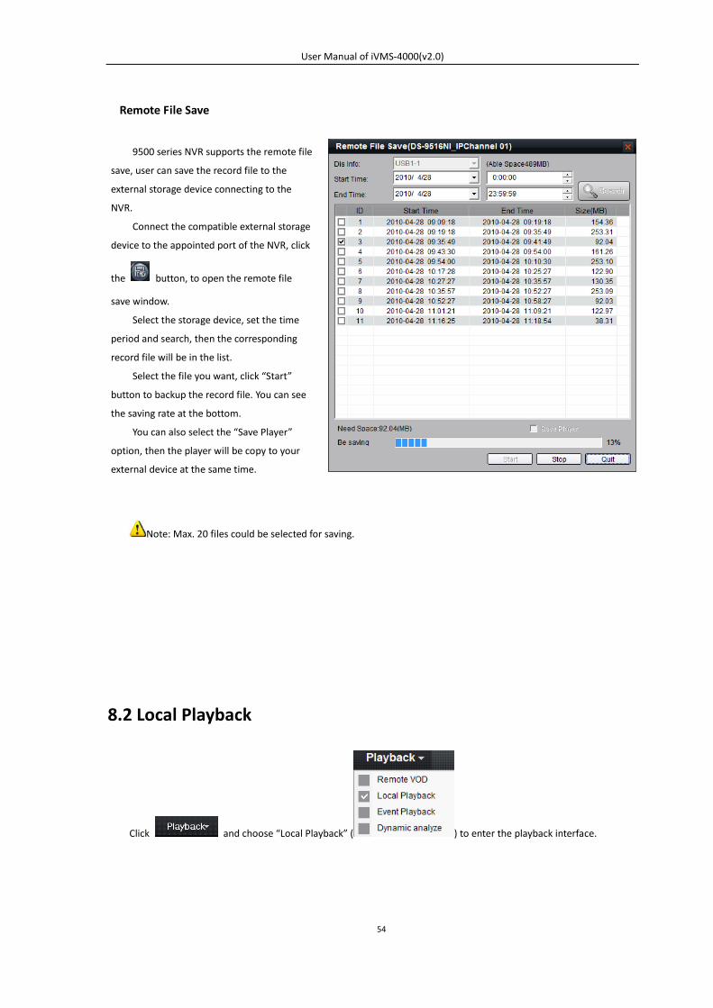
Remote File Save
Note: Max. 20 files could be selected for saving.
8.2 Local Playback
Click and choose “Local Playback” ( ) to enter the playback interface.
9500 series NVR supports the remote file
save, user can save the record file to the
external storage device connecting to the
NVR.
Connect the compatible external storage
device to the appointed port of the NVR, click
the button, to open the remote file
save window.
Select the storage device, set the time
period and search, then the corresponding
record file will be in the list.
Select the file you want, click “Start”
button to backup the record file. You can see
the saving rate at the bottom.
You can also select the “Save Player”
option, then the player will be copy to your
external device at the same time.
User Manual of iVMS-4000(v2.0)
55
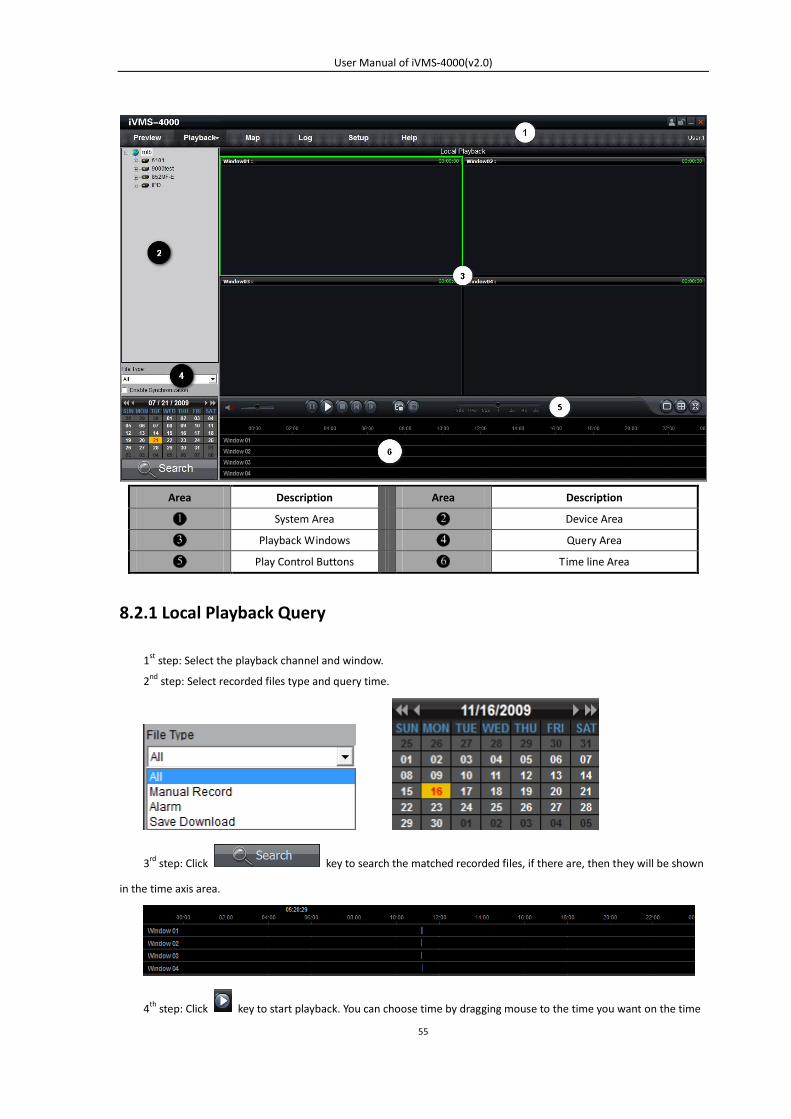
Area Description Area Description
System Area Device Area
Playback Windows Query Area
Play Control Buttons Time line Area
8.2.1 Local Playback Query
1st step: Select the playback channel and window.
2nd step: Select recorded files type and query time.
3rd step: Click key to search the matched recorded files, if there are, then they will be shown
in the time axis area.
4th step: Click key to start playback. You can choose time by dragging mouse to the time you want on the time
User Manual of iVMS-4000(v2.0)
56
axis.
Select one channel then drag into playback window. If there is recorded file in this day, software will play back it
from the very beginning of this day.
Note: If select , then the 4 windows will play back record files
synchronously. If they are on different time point currently, the others will go to the same time point of the selected
window.
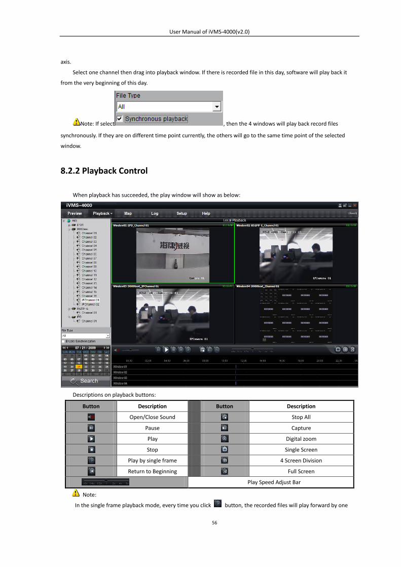
8.2.2 Playback Control
When playback has succeeded, the play window will show as below:
Descriptions on playback buttons:
Button Description Button Description
Open/Close Sound Stop All
Pause Capture
Play Digital zoom
Stop Single Screen
Play by single frame 4 Screen Division
Return to Beginning Full Screen
Play Speed Adjust Bar
Note:
In the single frame playback mode, every time you click button, the recorded files will play forward by one
User Manual of iVMS-4000(v2.0)
57
frame.
Only one window audio can be opened at the same time when in VOD mode. If the audio of next window opens
then the audio of previous window will be closed.
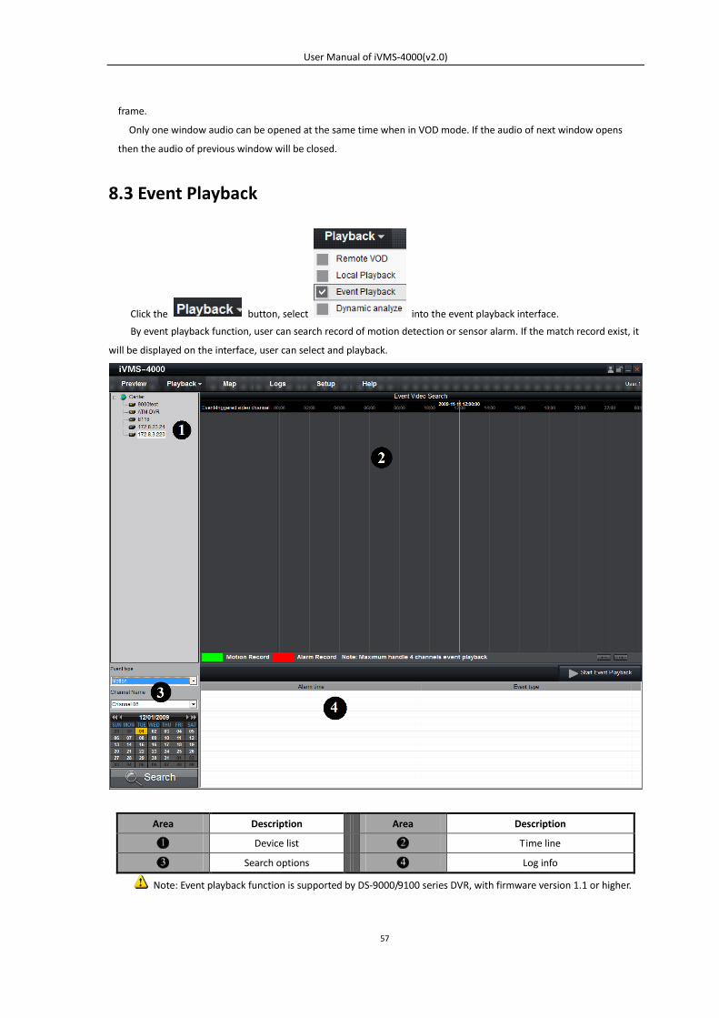
8.3 Event Playback
Click the button, select into the event playback interface.
By event playback function, user can search record of motion detection or sensor alarm. If the match record exist, it
will be displayed on the interface, user can select and playback.
Area Description Area Description
Device list Time line
Search options Log info
Note: Event playback function is supported by DS-9000/9100 series DVR, with firmware version 1.1 or higher.
User Manual of iVMS-4000(v2.0)
58
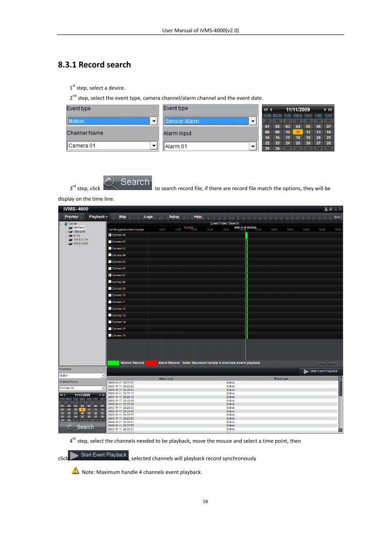
8.3.1 Record search
1st step, select a device.
2nd step, select the event type, camera channel/alarm channel and the event date.
3rd step, click to search record file, if there are record file match the options, they will be
display on the time line.
4th step, select the channels needed to be playback, move the mouse and select a time point, then
click , selected channels will playback record synchronously
Note: Maximum handle 4 channels event playback.
User Manual of iVMS-4000(v2.0)
59
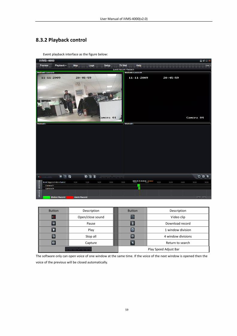
8.3.2 Playback control
Event playback interface as the figure below:
Button Description Button Description
Open/close sound Video clip
Pause Download record
Play 1 window division
Stop all 4 window divisions
Capture Return to search
Play Speed Adjust Bar
The software only can open voice of one window at the same time. If the voice of the next window is opened then the
voice of the previous will be closed automatically.
User Manual of iVMS-4000(v2.0)
60
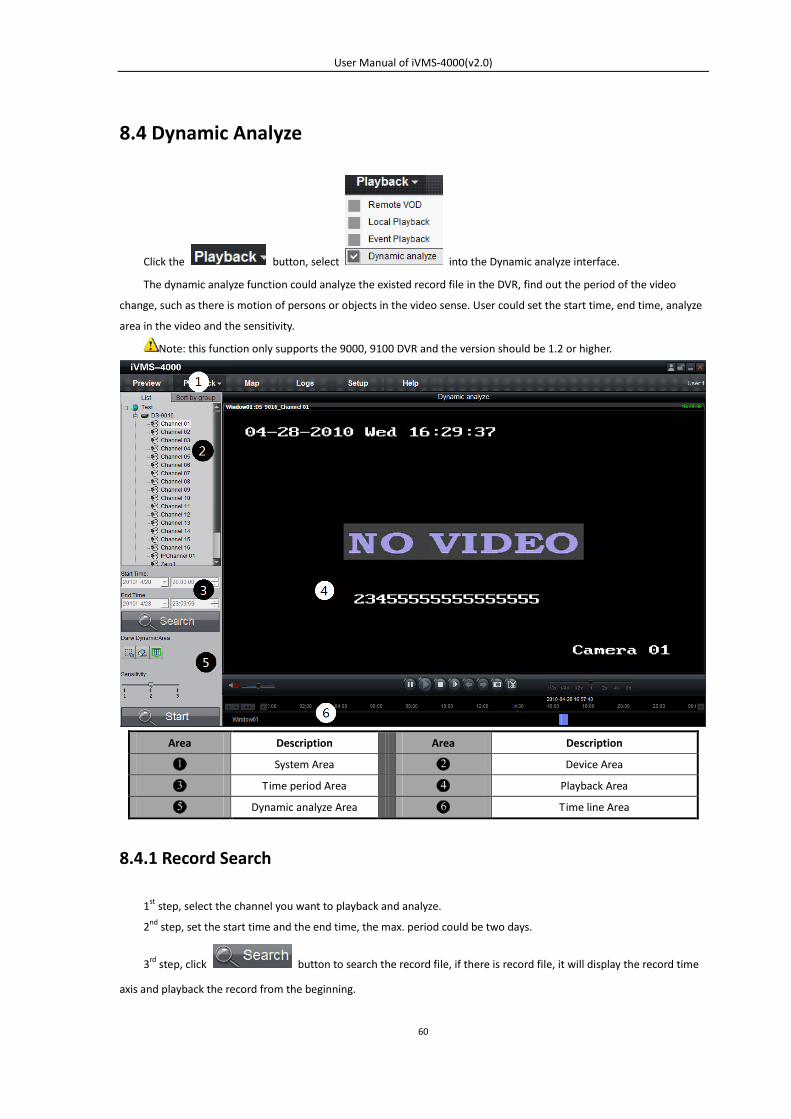
8.4 Dynamic Analyze
Click the button, select into the Dynamic analyze interface.
The dynamic analyze function could analyze the existed record file in the DVR, find out the period of the video
change, such as there is motion of persons or objects in the video sense. User could set the start time, end time, analyze
area in the video and the sensitivity.
Note: this function only supports the 9000, 9100 DVR and the version should be 1.2 or higher.
Area Description Area Description
System Area Device Area
Time period Area Playback Area
Dynamic analyze Area Time line Area
8.4.1 Record Search
1st step, select the channel you want to playback and analyze.
2nd step, set the start time and the end time, the max. period could be two days.
3rd step, click button to search the record file, if there is record file, it will display the record time
axis and playback the record from the beginning.
User Manual of iVMS-4000(v2.0)
61
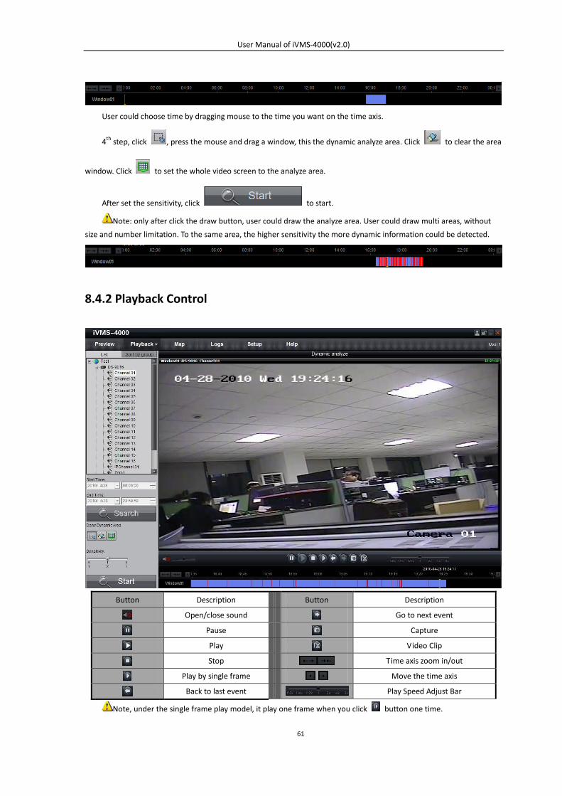
User could choose time by dragging mouse to the time you want on the time axis.
4th step, click , press the mouse and drag a window, this the dynamic analyze area. Click to clear the area
window. Click to set the whole video screen to the analyze area.
After set the sensitivity, click to start.
Note: only after click the draw button, user could draw the analyze area. User could draw multi areas, without
size and number limitation. To the same area, the higher sensitivity the more dynamic information could be detected.
8.4.2 Playback Control
Button Description Button Description
Open/close sound Go to next event
Pause Capture
Play Video Clip
Stop Time axis zoom in/out
Play by single frame Move the time axis
Back to last event Play Speed Adjust Bar
Note, under the single frame play model, it play one frame when you click button one time.

User Manual of iVMS-4000(v2.0)
62
Playback capture
User can also get the capture by clicking button, and you will see the pop up message. Click the picture to
open the capture and click the path to open the capture folder.
Last Event, Next Event
By the dynamic analyze function, if user detected multi record clips, click or to select between them.
User Manual of iVMS-4000(v2.0)
63
Chapter 9 Remote Configuration
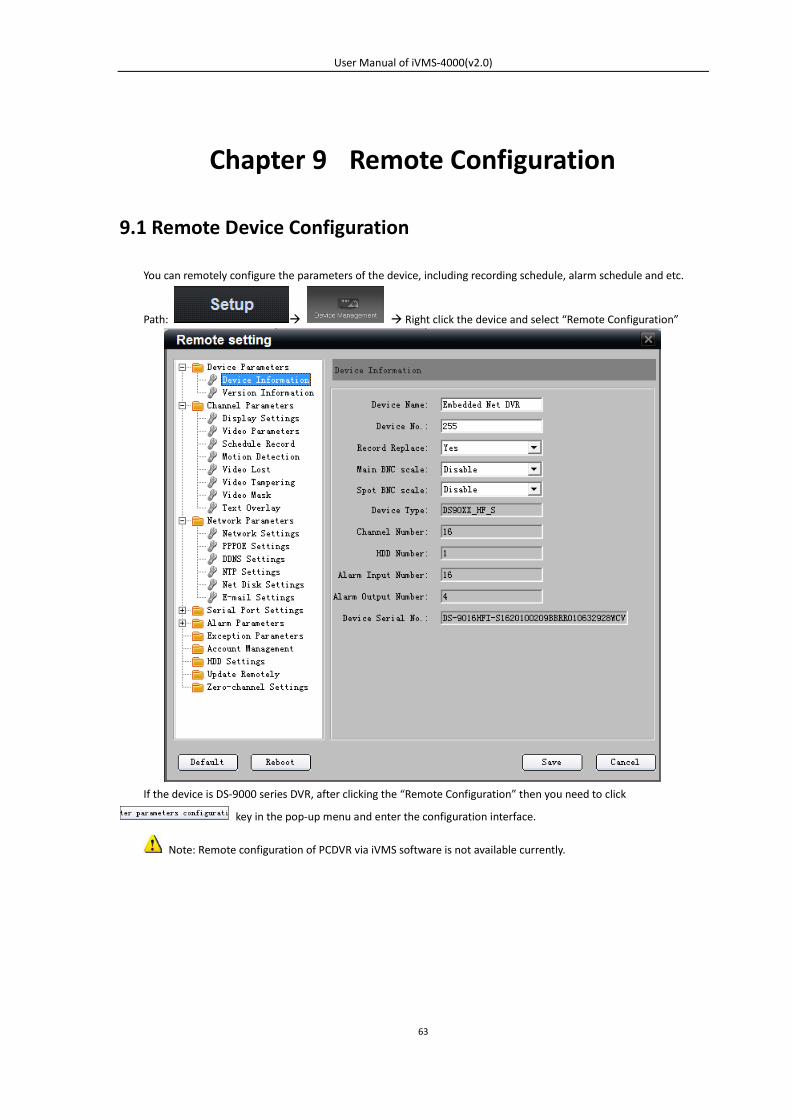
9.1 Remote Device Configuration
You can remotely configure the parameters of the device, including recording schedule, alarm schedule and etc.
Path: Right click the device and select “Remote Configuration”
If the device is DS-9000 series DVR, after clicking the “Remote Configuration” then you need to click
key in the pop-up menu and enter the configuration interface.
Note: Remote configuration of PCDVR via iVMS software is not available currently.
User Manual of iVMS-4000(v2.0)
64
9.1.1 Remote Recording Configuration
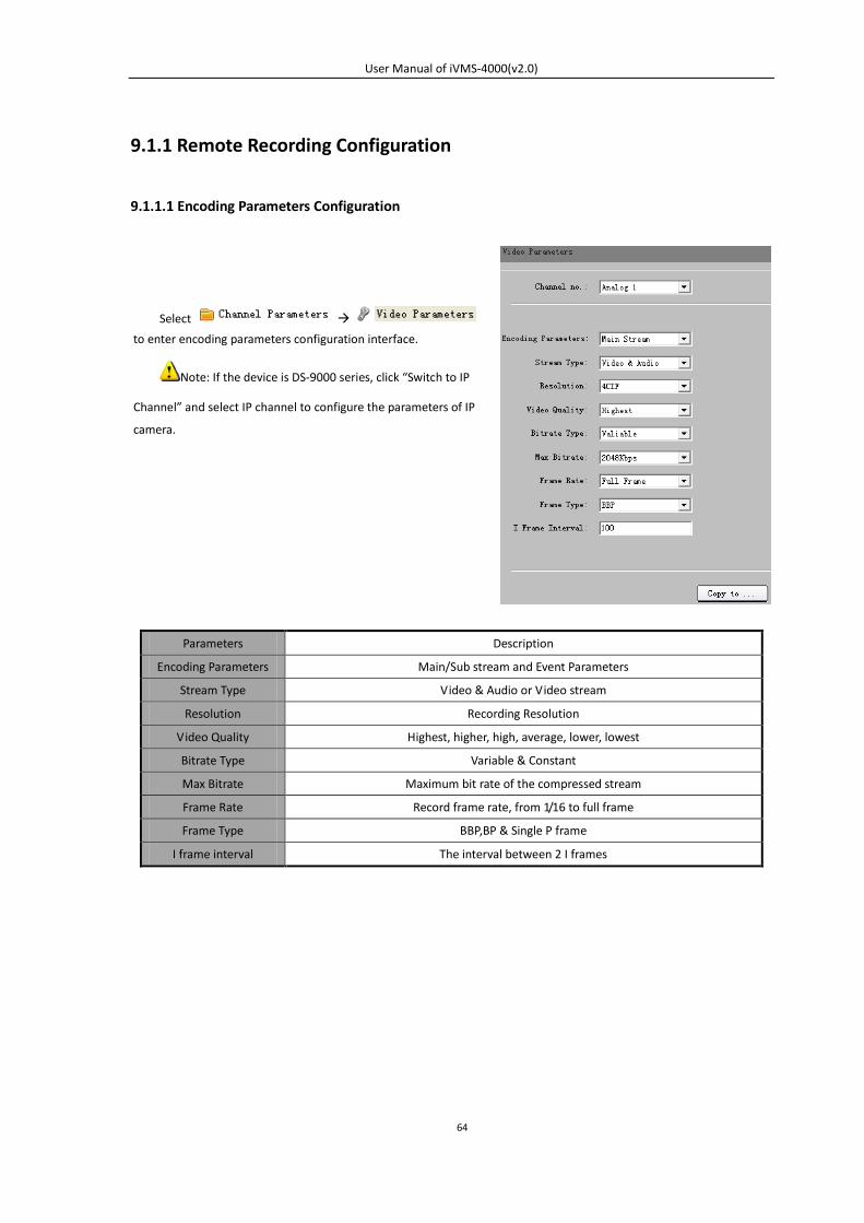
9.1.1.1 Encoding Parameters Configuration
Parameters Description
Encoding Parameters Main/Sub stream and Event Parameters
Stream Type Video & Audio or Video stream
Resolution Recording Resolution
Video Quality Highest, higher, high, average, lower, lowest
Bitrate Type Variable & Constant
Max Bitrate Maximum bit rate of the compressed stream
Frame Rate Record frame rate, from 1/16 to full frame
Frame Type BBP,BP & Single P frame
I frame interval The interval between 2 I frames
Select
to enter encoding parameters configuration interface.
Note: If the device is DS-9000 series, click “Switch to IP
Channel” and select IP channel to configure the parameters of IP
camera.
User Manual of iVMS-4000(v2.0)
65
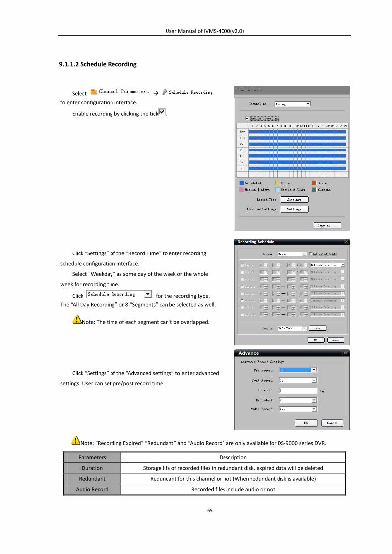
9.1.1.2 Schedule Recording
Note: “Recording Expired” “Redundant” and “Audio Record” are only available for DS-9000 series DVR.
Parameters Description
Duration Storage life of recorded files in redundant disk, expired data will be deleted
Redundant Redundant for this channel or not (When redundant disk is available)
Audio Record Recorded files include audio or not
Select
to enter configuration interface.
Enable recording by clicking the tick .
Click “Settings” of the “Record Time” to enter recording
schedule configuration interface.
Select “Weekday” as some day of the week or the whole
week for recording time.
Click for the recording type.
The “All Day Recording” or 8 “Segments” can be selected as well.
Note: The time of each segment can’t be overlapped.
Click “Settings” of the “Advanced settings” to enter advanced
settings. User can set pre/post record time.
User Manual of iVMS-4000(v2.0)
66
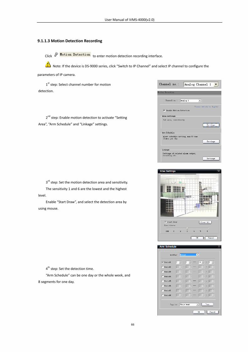
9.1.1.3 Motion Detection Recording
Click to enter motion detection recording interface.
Note: If the device is DS-9000 series, click “Switch to IP Channel” and select IP channel to configure the
parameters of IP camera.
2nd step: Enable motion detection to activate “Setting
Area”, “Arm Schedule” and “Linkage” settings.
1st step: Select channel number for motion
detection.
3rd step: Set the motion detection area and sensitivity.
The sensitivity 1 and 6 are the lowest and the highest
level.
Enable “Start Draw”, and select the detection area by
using mouse.
4th step: Set the detection time.
“Arm Schedule” can be one day or the whole week, and
8 segments for one day.
User Manual of iVMS-4000(v2.0)
67
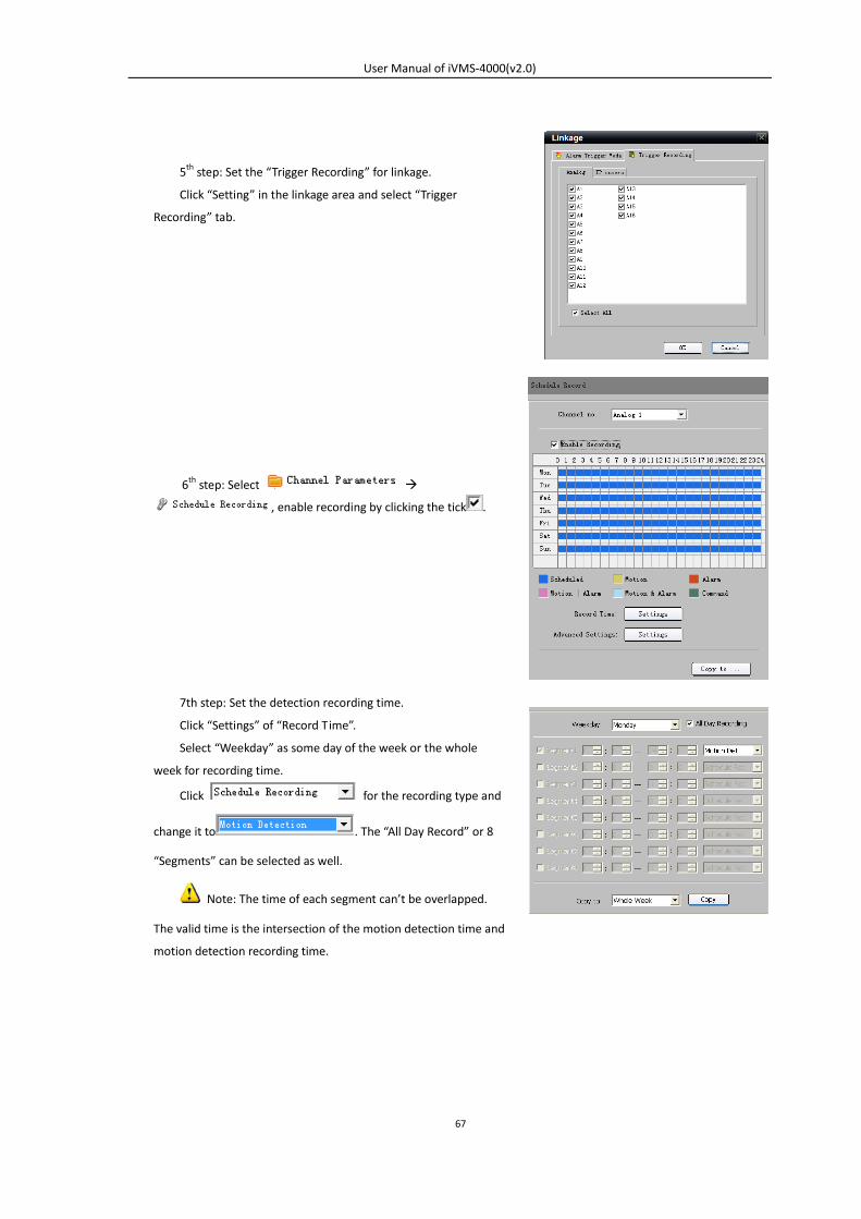
7th step: Set the detection recording time.
Click “Settings” of “Record Time”.
Select “Weekday” as some day of the week or the whole
week for recording time.
Click for the recording type and
change it to . The “All Day Record” or 8
“Segments” can be selected as well.
Note: The time of each segment can’t be overlapped.
The valid time is the intersection of the motion detection time and
motion detection recording time.
5th step: Set the “Trigger Recording” for linkage.
Click “Setting” in the linkage area and select “Trigger
Recording” tab.
6th step: Select
, enable recording by clicking the tick .
User Manual of iVMS-4000(v2.0)
68
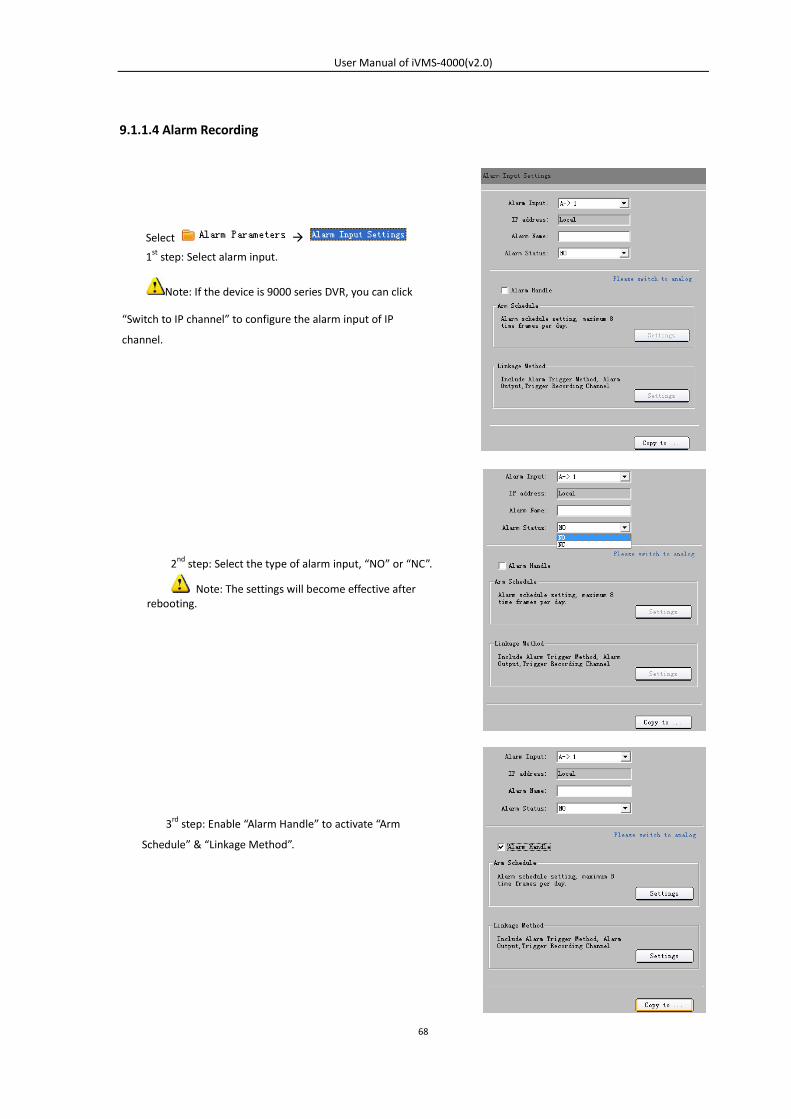
9.1.1.4 Alarm Recording
Select
1st step: Select alarm input.
Note: If the device is 9000 series DVR, you can click
“Switch to IP channel” to configure the alarm input of IP
channel.
2nd step: Select the type of alarm input, “NO” or “NC”.
Note: The settings will become effective after rebooting.
3rd step: Enable “Alarm Handle” to activate “Arm
Schedule” & “Linkage Method”.
User Manual of iVMS-4000(v2.0)
69
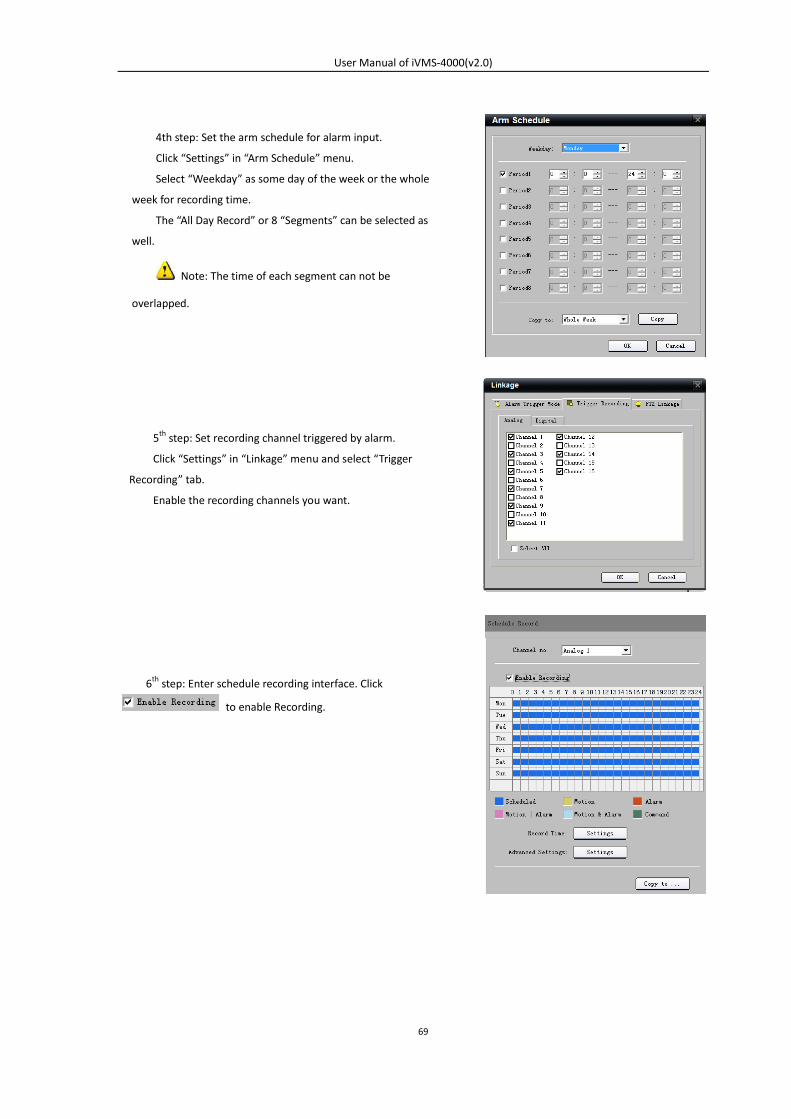
4th step: Set the arm schedule for alarm input.
Click “Settings” in “Arm Schedule” menu.
Select “Weekday” as some day of the week or the whole
week for recording time.
The “All Day Record” or 8 “Segments” can be selected as
well.
Note: The time of each segment can not be
overlapped.
5th step: Set recording channel triggered by alarm.
Click “Settings” in “Linkage” menu and select “Trigger
Recording” tab.
Enable the recording channels you want.
6th step: Enter schedule recording interface. Click
to enable Recording.
User Manual of iVMS-4000(v2.0)
70
9.1.1.5 Other Recording Modes
Other Recording Modes are including “Motion detection & Alarm”, “Motion detection | Alarm”.
“&” means recording is triggered when two situations happened together;
“|” means recording is triggered when one of the situations happened.
The configurations are the same with “Motion detection recording” or “Alarm recording”.
9.1.2 Alarm
You can configure motion detection alarm, signal level alarm, video loss alarm and other alarm and linkage through
client software.
9.1.2.1 Motion Detection Alarm
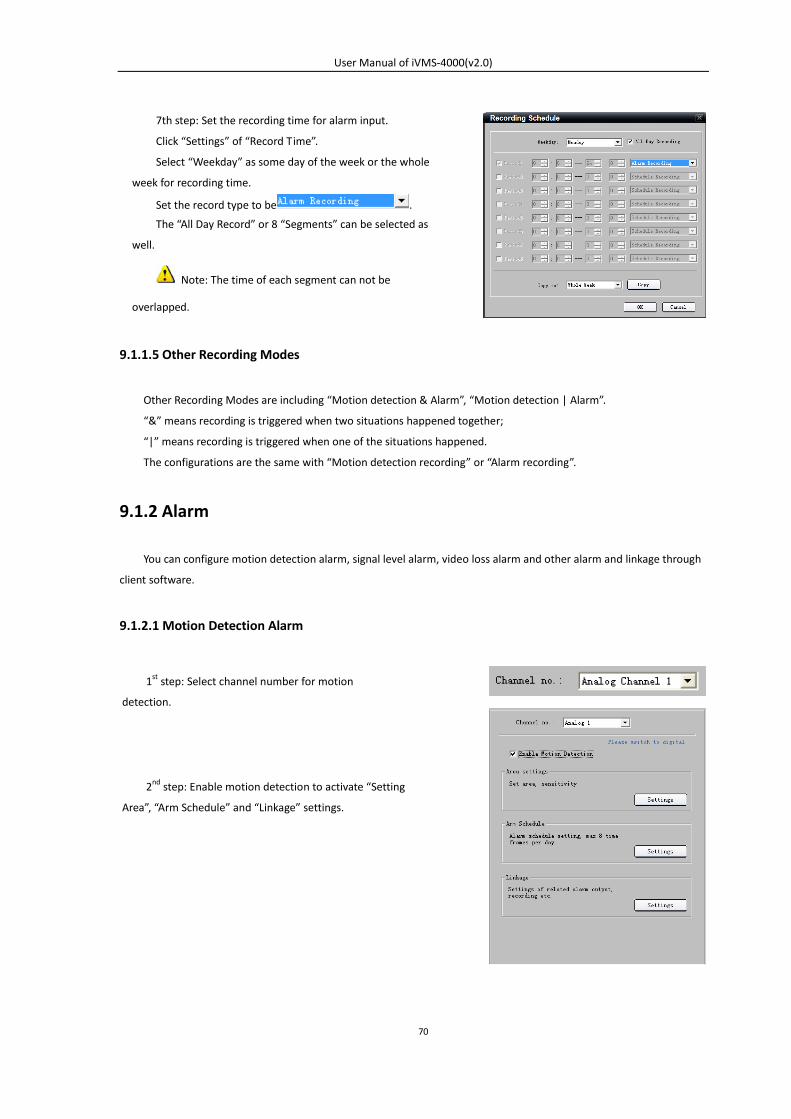
7th step: Set the recording time for alarm input.
Click “Settings” of “Record Time”.
Select “Weekday” as some day of the week or the whole
week for recording time.
Set the record type to be .
The “All Day Record” or 8 “Segments” can be selected as
well.
Note: The time of each segment can not be
overlapped.
2nd step: Enable motion detection to activate “Setting
Area”, “Arm Schedule” and “Linkage” settings.
1st step: Select channel number for motion
detection.
User Manual of iVMS-4000(v2.0)
71
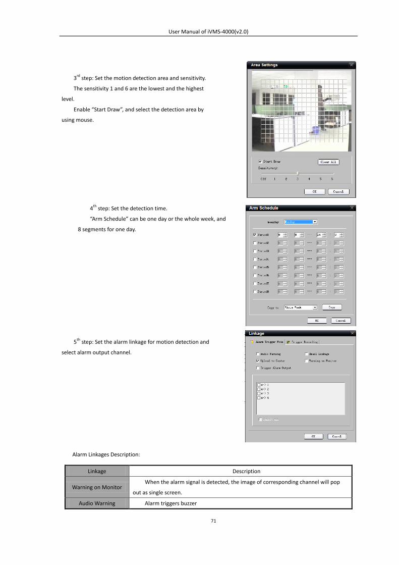
Alarm Linkages Description:
Linkage Description
Warning on Monitor When the alarm signal is detected, the image of corresponding channel will pop
out as single screen.
Audio Warning Alarm triggers buzzer
5th step: Set the alarm linkage for motion detection and
select alarm output channel.
3rd step: Set the motion detection area and sensitivity.
The sensitivity 1 and 6 are the lowest and the highest
level.
Enable “Start Draw”, and select the detection area by
using mouse.
4th step: Set the detection time.
“Arm Schedule” can be one day or the whole week, and
8 segments for one day.
User Manual of iVMS-4000(v2.0)
72
Upload to Center Upload the alarm signal to the center, such as client software
E-mail Linkage When the alarm signal is detected, the client software will send the email to the
designated mailbox.
Trigger Alarm Output Trigger alarm output of the device; if the device is DS-9000 series, triggering alarm
output of IP channel can be selected as well.
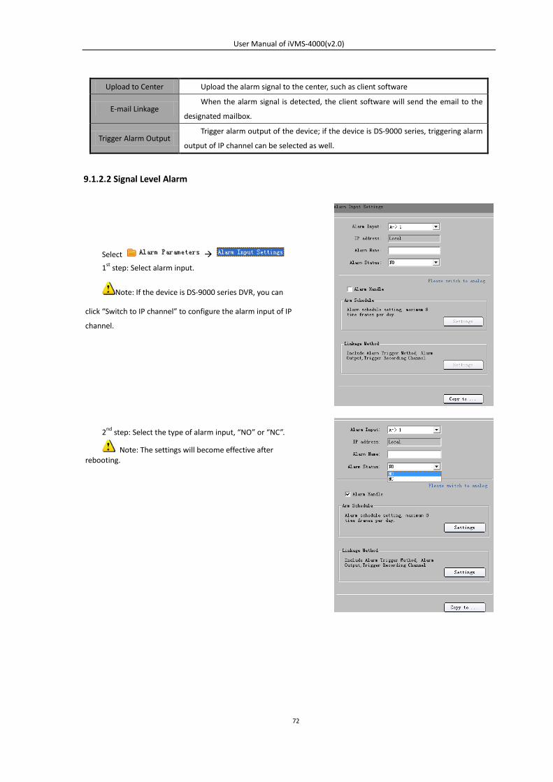
9.1.2.2 Signal Level Alarm
Select
1st step: Select alarm input.
Note: If the device is DS-9000 series DVR, you can
click “Switch to IP channel” to configure the alarm input of IP
channel.
2nd step: Select the type of alarm input, “NO” or “NC”.
Note: The settings will become effective after rebooting.
User Manual of iVMS-4000(v2.0)
73
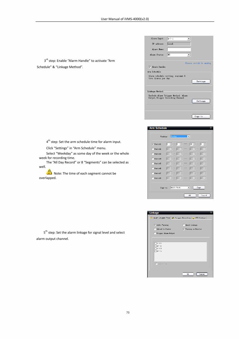
5th step: Set the alarm linkage for signal level and select
alarm output channel.
3rd step: Enable “Alarm Handle” to activate “Arm
Schedule” & “Linkage Method”.
4th step: Set the arm schedule time for alarm input.
Click “Settings” in “Arm Schedule” menu.
Select “Weekday” as some day of the week or the whole week for recording time.
The “All Day Record” or 8 “Segments” can be selected as well.
Note: The time of each segment cannot be overlapped.
User Manual of iVMS-4000(v2.0)
74
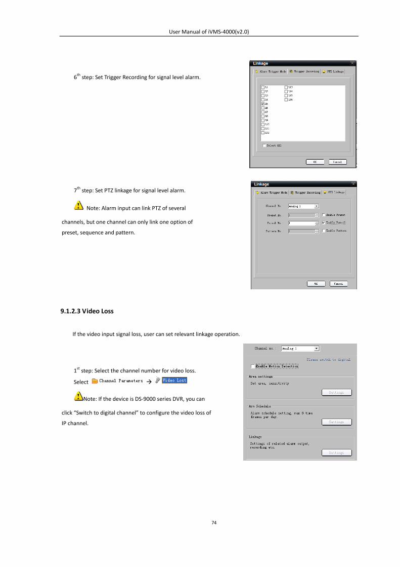
9.1.2.3 Video Loss
If the video input signal loss, user can set relevant linkage operation.
7th step: Set PTZ linkage for signal level alarm.
Note: Alarm input can link PTZ of several
channels, but one channel can only link one option of
preset, sequence and pattern.
1st step: Select the channel number for video loss.
Select
Note: If the device is DS-9000 series DVR, you can
click “Switch to digital channel” to configure the video loss of
IP channel.
6th step: Set Trigger Recording for signal level alarm.
User Manual of iVMS-4000(v2.0)
75
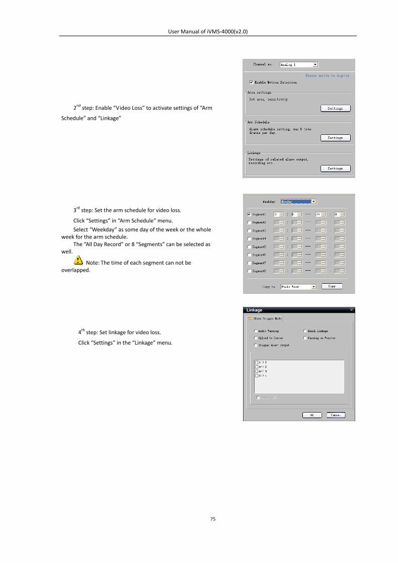
2nd step: Enable “Video Loss” to activate settings of “Arm
Schedule” and “Linkage”
3rd step: Set the arm schedule for video loss.
Click “Settings” in “Arm Schedule” menu.
Select “Weekday” as some day of the week or the whole week for the arm schedule.
The “All Day Record” or 8 “Segments” can be selected as well.
Note: The time of each segment can not be overlapped.
4th step: Set linkage for video loss.
Click “Settings” in the “Linkage” menu.
User Manual of iVMS-4000(v2.0)
76
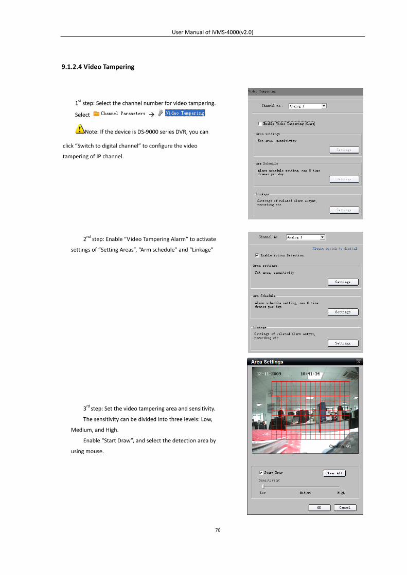
9.1.2.4 Video Tampering
1st step: Select the channel number for video tampering.
Select
Note: If the device is DS-9000 series DVR, you can
click “Switch to digital channel” to configure the video
tampering of IP channel.
3rd step: Set the video tampering area and sensitivity.
The sensitivity can be divided into three levels: Low,
Medium, and High.
Enable “Start Draw”, and select the detection area by
using mouse.
2nd step: Enable “Video Tampering Alarm” to activate
settings of “Setting Areas”, “Arm schedule” and “Linkage”
User Manual of iVMS-4000(v2.0)
77
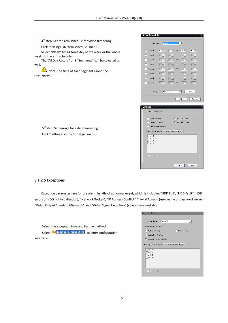
9.1.2.5 Exceptions
Exception parameters are for the alarm handle of abnormal event, which is including “HDD Full”, “HDD Fault” (HDD
errors or HDD not initialization), “Network Broken”, “IP Address Conflict”, “Illegal Access” (user name or password wrong),
“Video Output Standard Mismatch” and “Video Signal Exception” (video signal unstable).
4th step: Set the arm schedule for video tampering.
Click “Settings” in “Arm schedule” menu.
Select “Weekday” as some day of the week or the whole week for the arm schedule.
The “All Day Record” or 8 “Segments” can be selected as well.
Note: The time of each segment cannot be overlapped.
5th step: Set linkage for video tampering.
Click “Settings” in the “Linkage” menu.
Select the exception type and handle method.
Select to enter configuration
interface.
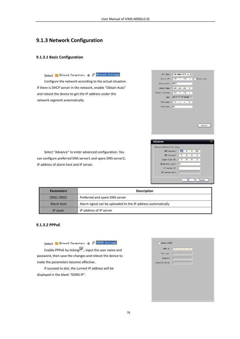
User Manual of iVMS-4000(v2.0)
78
9.1.3 Network Configuration
9.1.3.1 Basic Configuration
Parameters Description
DNS1 DNS2 Preferred and spare DNS server
Alarm host Alarm signal can be uploaded to the IP address automatically
IP sever IP address of IP server
9.1.3.2 PPPoE
Select
Configure the network according to the actual situation.
If there is DHCP server in the network, enable “Obtain Auto”
and reboot the device to get the IP address under this
network segment automatically.
Select “Advance” to enter advanced configuration. You
can configure preferred DNS server1 and spare DNS server2,
IP address of alarm host and IP server.
Select
Enable PPPoE by ticking , input the user name and
password, then save the changes and reboot the device to
make the parameters become effective.
If succeed to dial, the current IP address will be
displayed in the blank “DDNS IP”.
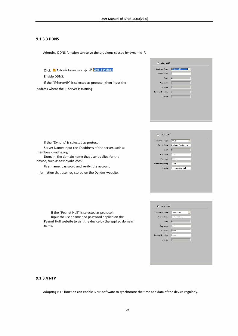
User Manual of iVMS-4000(v2.0)
79
9.1.3.3 DDNS
Adopting DDNS function can solve the problems caused by dynamic IP.
9.1.3.4 NTP
Adopting NTP function can enable iVMS software to synchronize the time and data of the device regularly.
Click
Enable DDNS.
If the “IPServerIP” is selected as protocol, then input the
address where the IP server is running.
If the “Dyndns” is selected as protocol:
Server Name: Input the IP address of the server, such as members.dyndns.org;
Domain: the domain name that user applied for the device, such as test.dynlia.com;
User name, password and verify: the account
information that user registered on the Dyndns website.
If the “Peanut Hull” is selected as protocol: Input the user name and password applied on the
Peanut Hull website to visit the device by the applied domain name.
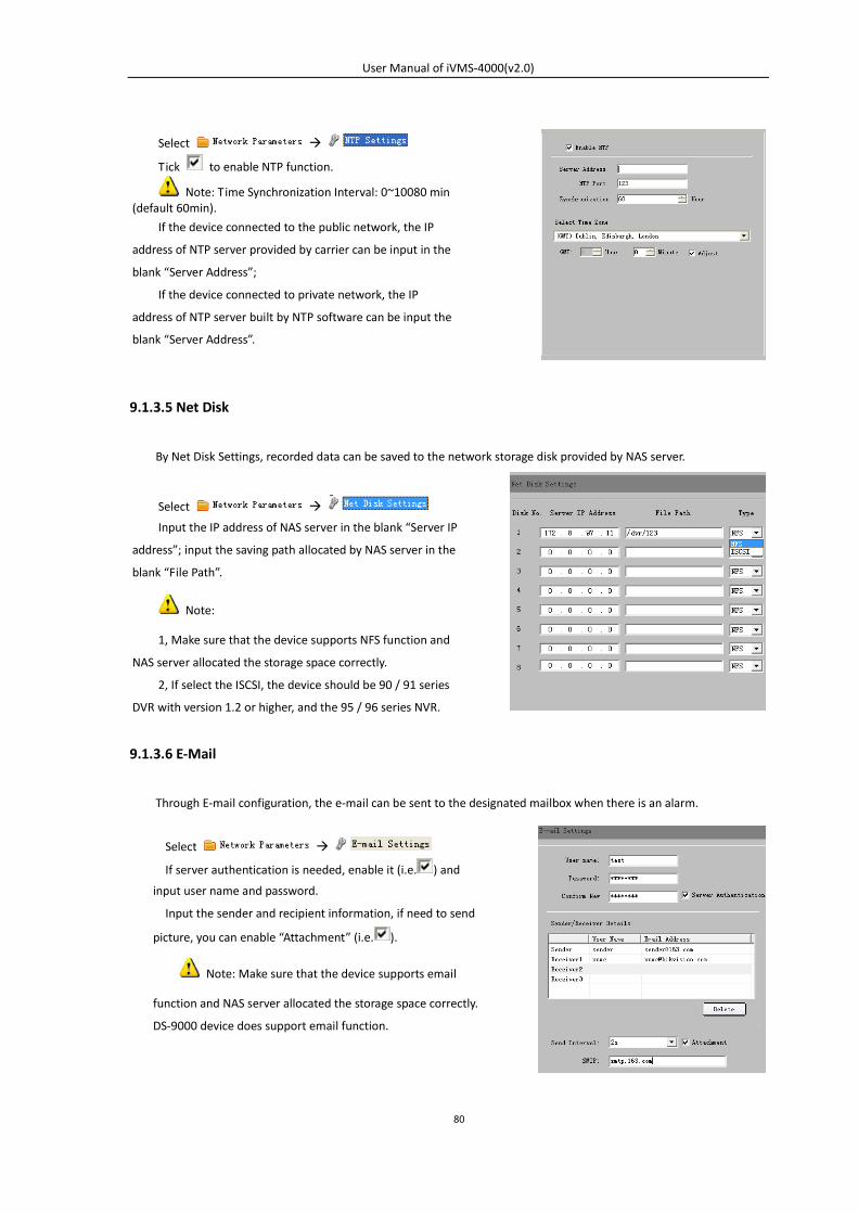
User Manual of iVMS-4000(v2.0)
80
9.1.3.5 Net Disk
By Net Disk Settings, recorded data can be saved to the network storage disk provided by NAS server.
9.1.3.6 E-Mail
Through E-mail configuration, the e-mail can be sent to the designated mailbox when there is an alarm.
Select
Tick to enable NTP function.
Note: Time Synchronization Interval: 0~10080 min (default 60min).
If the device connected to the public network, the IP
address of NTP server provided by carrier can be input in the
blank “Server Address”;
If the device connected to private network, the IP
address of NTP server built by NTP software can be input the
blank “Server Address”.
Select
Input the IP address of NAS server in the blank “Server IP
address”; input the saving path allocated by NAS server in the
blank “File Path”.
Note:
1, Make sure that the device supports NFS function and
NAS server allocated the storage space correctly.
2, If select the ISCSI, the device should be 90 / 91 series
DVR with version 1.2 or higher, and the 95 / 96 series NVR.
Select
If server authentication is needed, enable it (i.e. ) and
input user name and password.
Input the sender and recipient information, if need to send
picture, you can enable “Attachment” (i.e. ).
Note: Make sure that the device supports email
function and NAS server allocated the storage space correctly.
DS-9000 device does support email function.
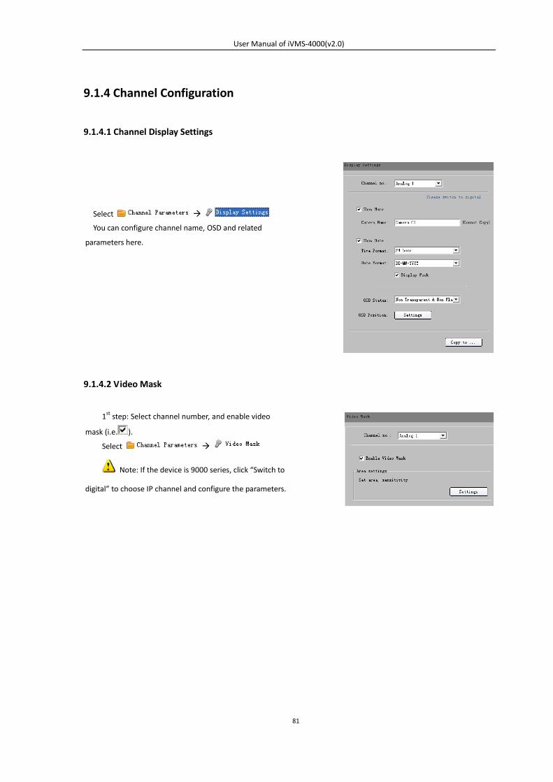
User Manual of iVMS-4000(v2.0)
81
9.1.4 Channel Configuration
9.1.4.1 Channel Display Settings
9.1.4.2 Video Mask
Select
You can configure channel name, OSD and related
parameters here.
1st step: Select channel number, and enable video
mask (i.e. ).
Select
Note: If the device is 9000 series, click “Switch to
digital” to choose IP channel and configure the parameters.
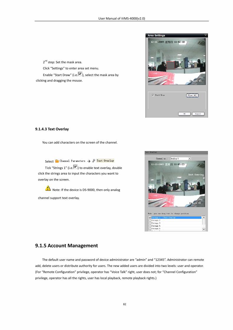
User Manual of iVMS-4000(v2.0)
82
9.1.4.3 Text Overlay
You can add characters on the screen of the channel.
9.1.5 Account Management
The default user name and password of device administrator are “admin” and “12345”. Administrator can remote
add, delete users or distribute authority for users. The new added users are divided into two levels: user and operator.
(For “Remote Configuration” privilege, operator has “Voice Talk” right, user does not; for “Channel Configuration”
privilege, operator has all the rights, user has local playback, remote playback rights.)
2nd step: Set the mask area.
Click “Settings” to enter area set menu.
Enable “Start Draw” (i.e. ), select the mask area by
clicking and dragging the mouse.
Select
Tick “Strings 1” (i.e. ) to enable text overlay, double
click the strings area to input the characters you want to
overlay on the screen.
Note: If the device is DS-9000, then only analog
channel support text overlay.
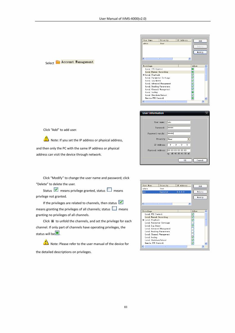
User Manual of iVMS-4000(v2.0)
83
Select
Click “Add” to add user.
Note: If you set the IP address or physical address,
and then only the PC with the same IP address or physical
address can visit the device through network.
Click “Modify” to change the user name and password; click
“Delete” to delete the user.
Status means privilege granted, status means
privilege not granted.
If the privileges are related to channels, then status
means granting the privileges of all channels; status means
granting no privileges of all channels.
Click to unfold the channels, and set the privilege for each
channel. If only part of channels have operating privileges, the
status will be .
Note: Please refer to the user manual of the device for
the detailed descriptions on privileges.
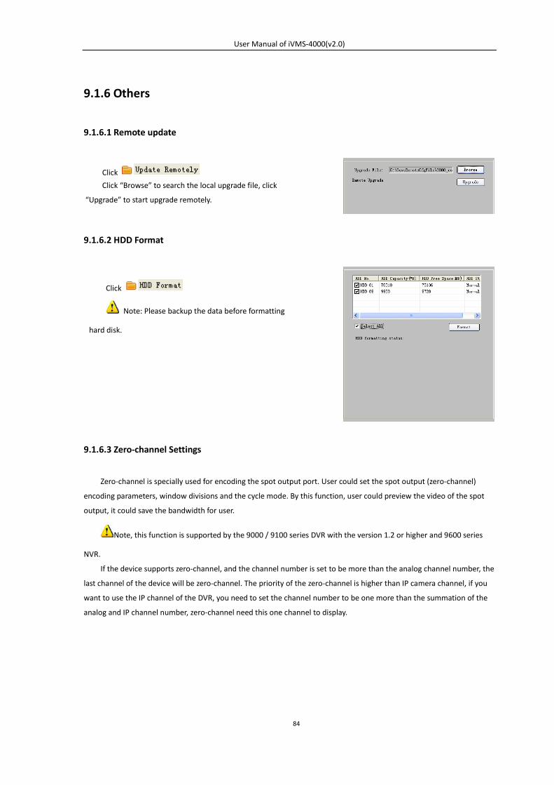
User Manual of iVMS-4000(v2.0)
84
9.1.6 Others
9.1.6.1 Remote update
9.1.6.2 HDD Format
9.1.6.3 Zero-channel Settings
Zero-channel is specially used for encoding the spot output port. User could set the spot output (zero-channel)
encoding parameters, window divisions and the cycle mode. By this function, user could preview the video of the spot
output, it could save the bandwidth for user.
Note, this function is supported by the 9000 / 9100 series DVR with the version 1.2 or higher and 9600 series
NVR.
If the device supports zero-channel, and the channel number is set to be more than the analog channel number, the
last channel of the device will be zero-channel. The priority of the zero-channel is higher than IP camera channel, if you
want to use the IP channel of the DVR, you need to set the channel number to be one more than the summation of the
analog and IP channel number, zero-channel need this one channel to display.
Click
Click “Browse” to search the local upgrade file, click
“Upgrade” to start upgrade remotely.
Click
Note: Please backup the data before formatting
hard disk.
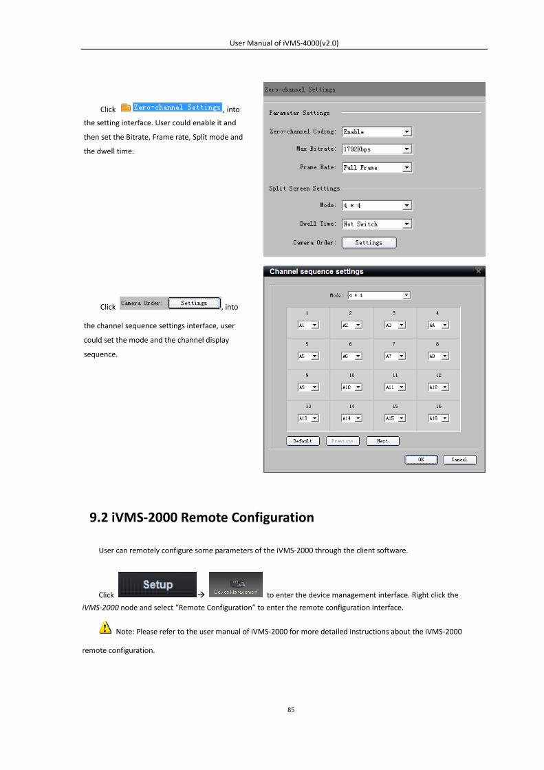
User Manual of iVMS-4000(v2.0)
85
9.2 iVMS-2000 Remote Configuration
User can remotely configure some parameters of the iVMS-2000 through the client software.
Click to enter the device management interface. Right click the
iVMS-2000 node and select “Remote Configuration” to enter the remote configuration interface.
Note: Please refer to the user manual of iVMS-2000 for more detailed instructions about the iVMS-2000
remote configuration.
Click , into
the setting interface. User could enable it and
then set the Bitrate, Frame rate, Split mode and
the dwell time.
Click , into
the channel sequence settings interface, user
could set the mode and the channel display
sequence.
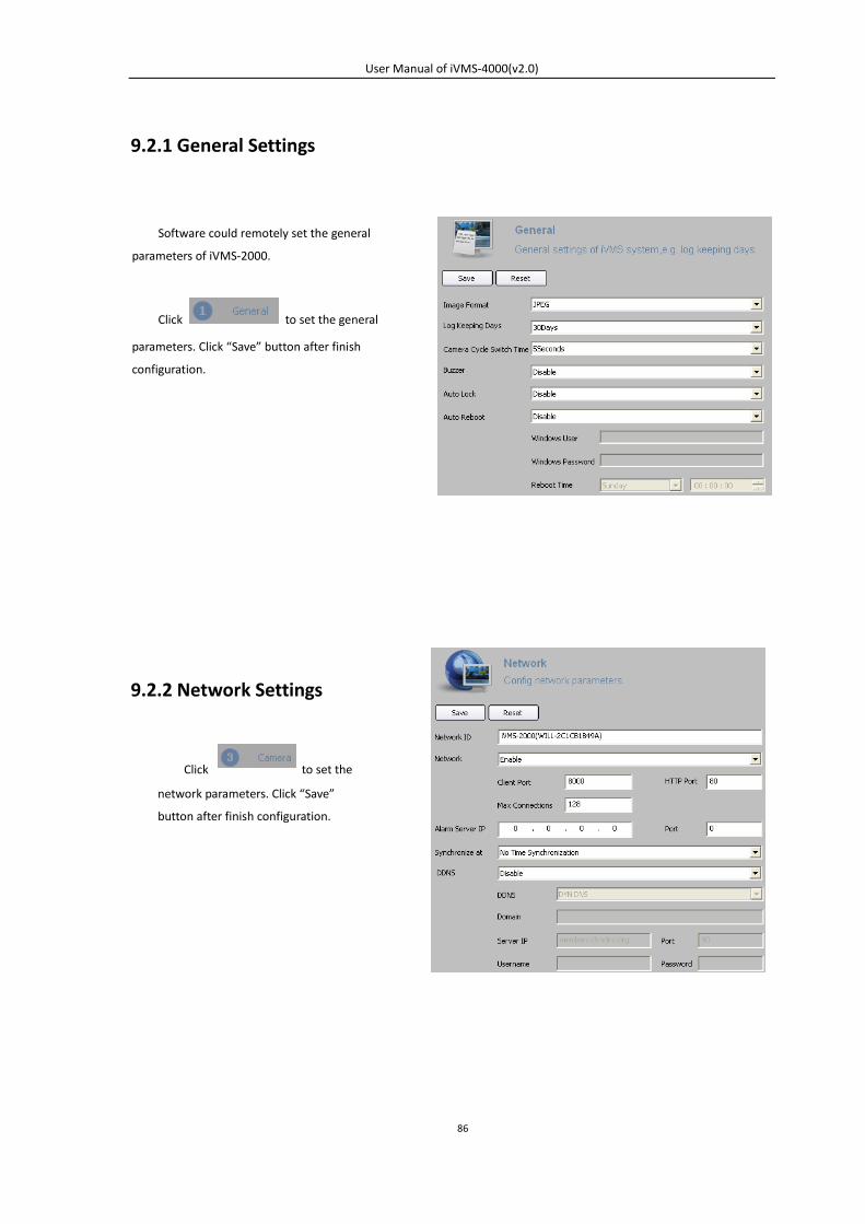
User Manual of iVMS-4000(v2.0)
86
9.2.1 General Settings
9.2.2 Network Settings
Software could remotely set the general
parameters of iVMS-2000.
Click to set the general
parameters. Click “Save” button after finish
configuration.
Click to set the
network parameters. Click “Save”
button after finish configuration.
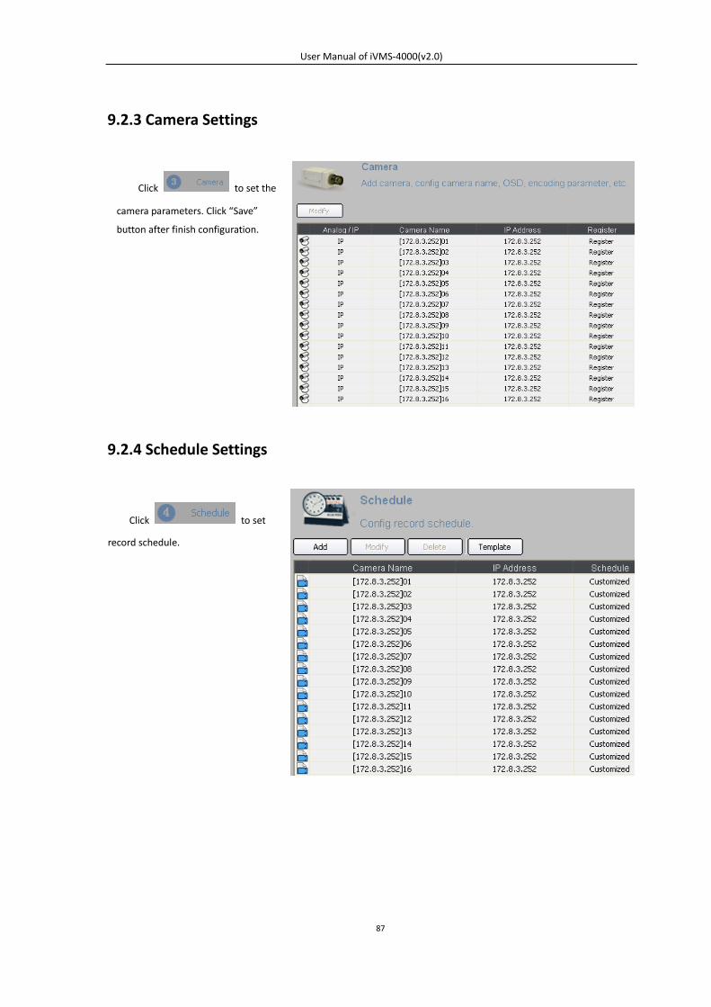
User Manual of iVMS-4000(v2.0)
87
9.2.3 Camera Settings
9.2.4 Schedule Settings
Click to set the
camera parameters. Click “Save”
button after finish configuration.
Click to set
record schedule.
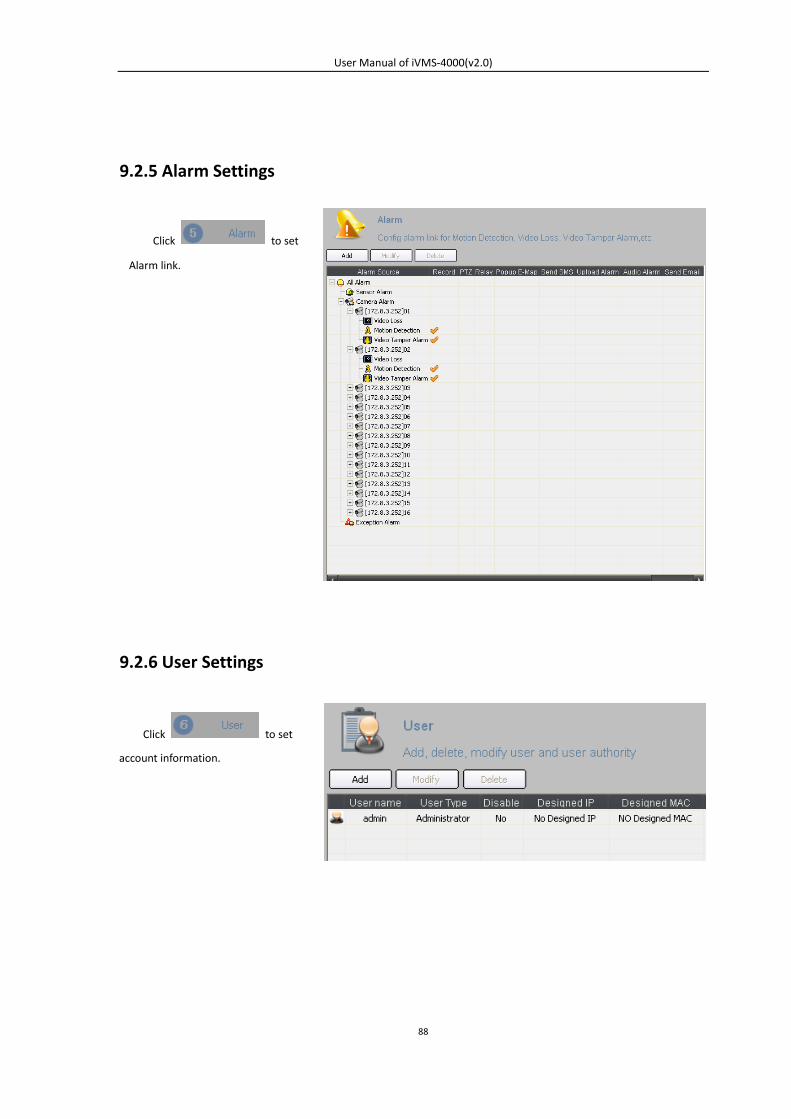
User Manual of iVMS-4000(v2.0)
88
9.2.5 Alarm Settings
9.2.6 User Settings
Click to set
Alarm link.
Click to set
account information.
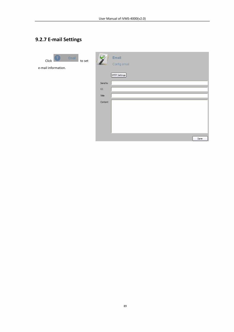
User Manual of iVMS-4000(v2.0)
89
9.2.7 E-mail Settings
Click to set
e-mail information.
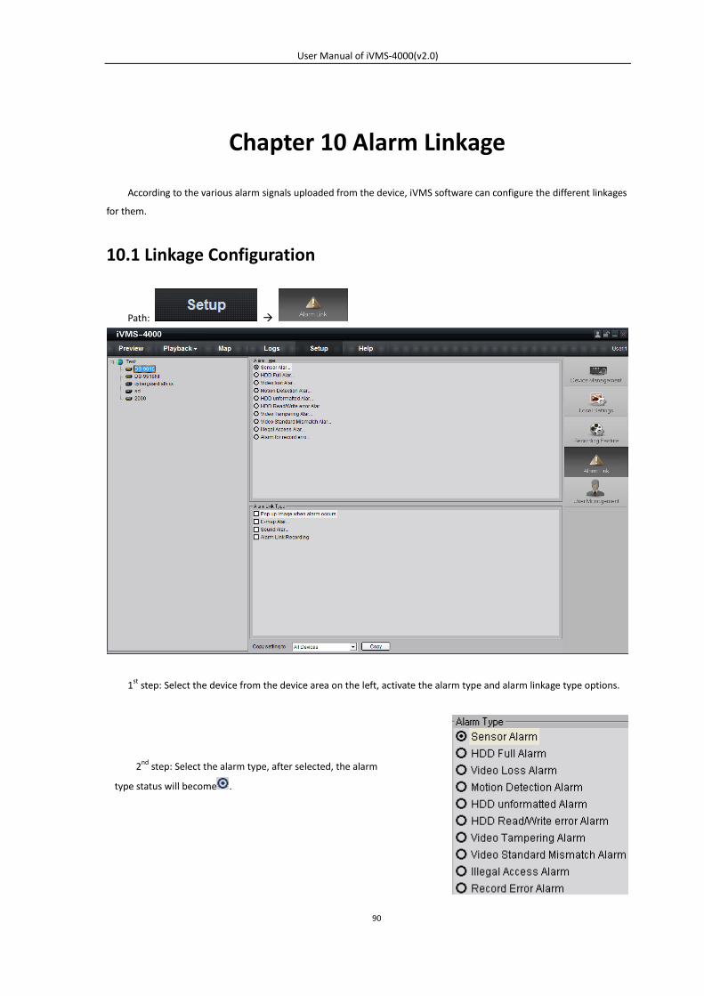
User Manual of iVMS-4000(v2.0)
90
Chapter 10 Alarm Linkage
According to the various alarm signals uploaded from the device, iVMS software can configure the different linkages
for them.
10.1 Linkage Configuration
Path:
1st
step: Select the device from the device area on the left, activate the alarm type and alarm linkage type options.
2nd step: Select the alarm type, after selected, the alarm
type status will become .
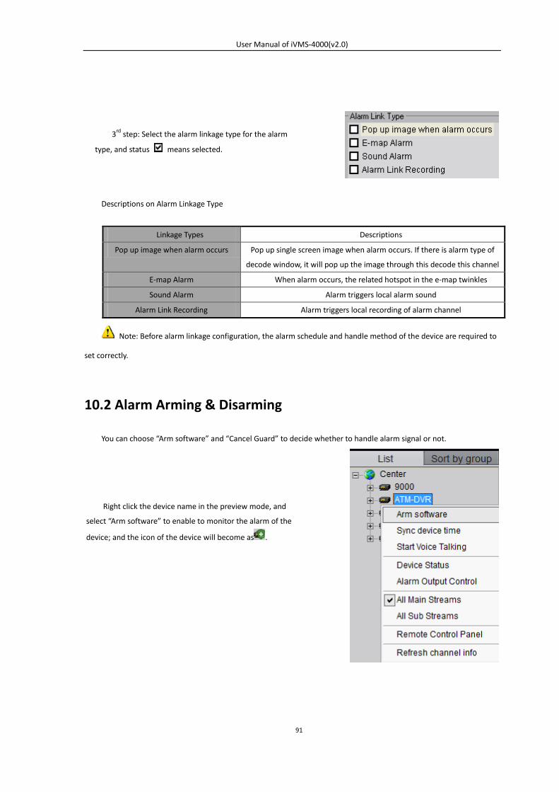
User Manual of iVMS-4000(v2.0)
91
Descriptions on Alarm Linkage Type
Linkage Types Descriptions
Pop up image when alarm occurs Pop up single screen image when alarm occurs. If there is alarm type of
decode window, it will pop up the image through this decode this channel
E-map Alarm When alarm occurs, the related hotspot in the e-map twinkles
Sound Alarm Alarm triggers local alarm sound
Alarm Link Recording Alarm triggers local recording of alarm channel
Note: Before alarm linkage configuration, the alarm schedule and handle method of the device are required to
set correctly.
10.2 Alarm Arming & Disarming
You can choose “Arm software” and “Cancel Guard” to decide whether to handle alarm signal or not.
3rd step: Select the alarm linkage type for the alarm
type, and status means selected.
Right click the device name in the preview mode, and
select “Arm software” to enable to monitor the alarm of the
device; and the icon of the device will become as .
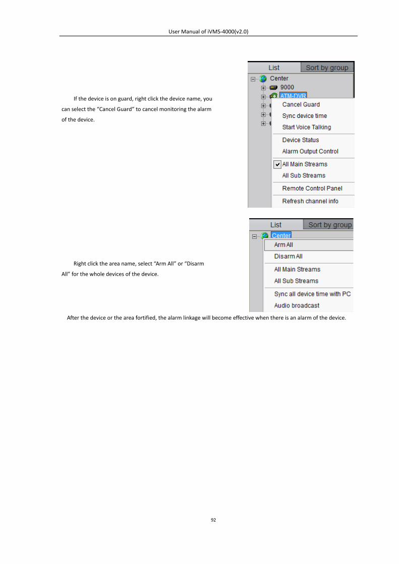
User Manual of iVMS-4000(v2.0)
92
After the device or the area fortified, the alarm linkage will become effective when there is an alarm of the device.
If the device is on guard, right click the device name, you
can select the “Cancel Guard” to cancel monitoring the alarm
of the device.
Right click the area name, select “Arm All” or “Disarm
All” for the whole devices of the device.
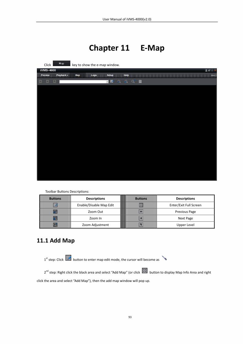
User Manual of iVMS-4000(v2.0)
93
Chapter 11 E-Map
Click key to show the e-map window.
Toolbar Buttons Descriptions:
Buttons Descriptions Buttons Descriptions
Enable/Disable Map Edit Enter/Exit Full Screen
Zoom Out Previous Page
Zoom In Next Page
Zoom Adjustment Upper Level
11.1 Add Map
1st step: Click button to enter map edit mode, the cursor will become as
2nd step: Right click the black area and select “Add Map” (or click button to display Map Info Area and right
click the area and select “Add Map”), then the add map window will pop up.
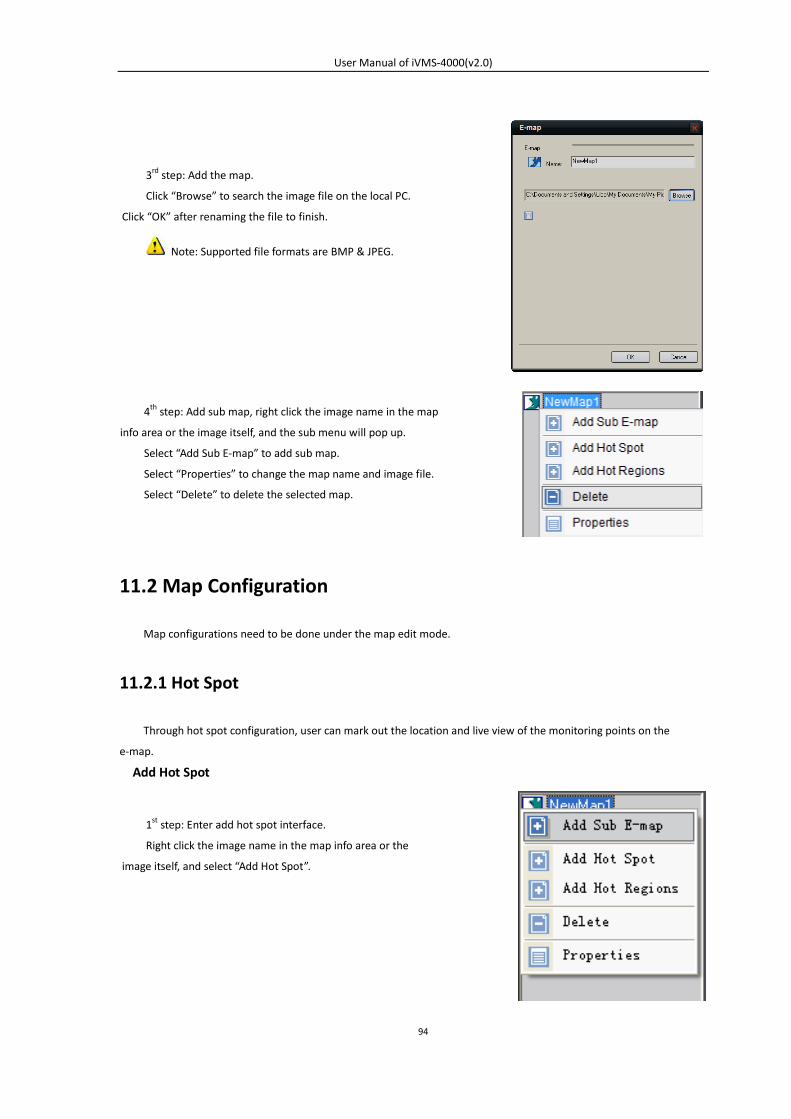
User Manual of iVMS-4000(v2.0)
94
11.2 Map Configuration
Map configurations need to be done under the map edit mode.
11.2.1 Hot Spot
Through hot spot configuration, user can mark out the location and live view of the monitoring points on the
e-map.
Add Hot Spot
3rd step: Add the map.
Click “Browse” to search the image file on the local PC.
Click “OK” after renaming the file to finish.
Note: Supported file formats are BMP & JPEG.
4th step: Add sub map, right click the image name in the map
info area or the image itself, and the sub menu will pop up.
Select “Add Sub E-map” to add sub map.
Select “Properties” to change the map name and image file.
Select “Delete” to delete the selected map.
1st step: Enter add hot spot interface.
Right click the image name in the map info area or the
image itself, and select “Add Hot Spot”.
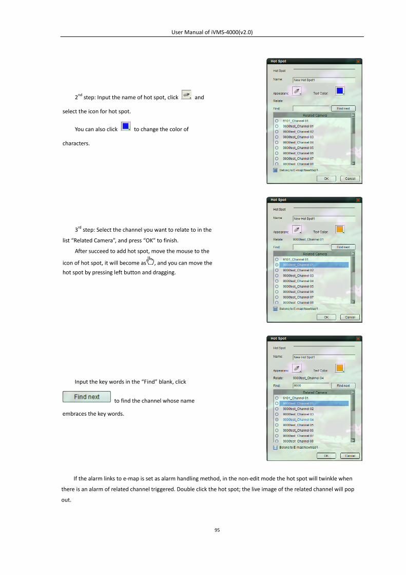
User Manual of iVMS-4000(v2.0)
95
If the alarm links to e-map is set as alarm handling method, in the non-edit mode the hot spot will twinkle when
there is an alarm of related channel triggered. Double click the hot spot; the live image of the related channel will pop
out.
2nd step: Input the name of hot spot, click and
select the icon for hot spot.
You can also click to change the color of
characters.
3rd step: Select the channel you want to relate to in the
list “Related Camera”, and press “OK” to finish.
After succeed to add hot spot, move the mouse to the
icon of hot spot, it will become as , and you can move the
hot spot by pressing left button and dragging.
Input the key words in the “Find” blank, click
to find the channel whose name
embraces the key words.
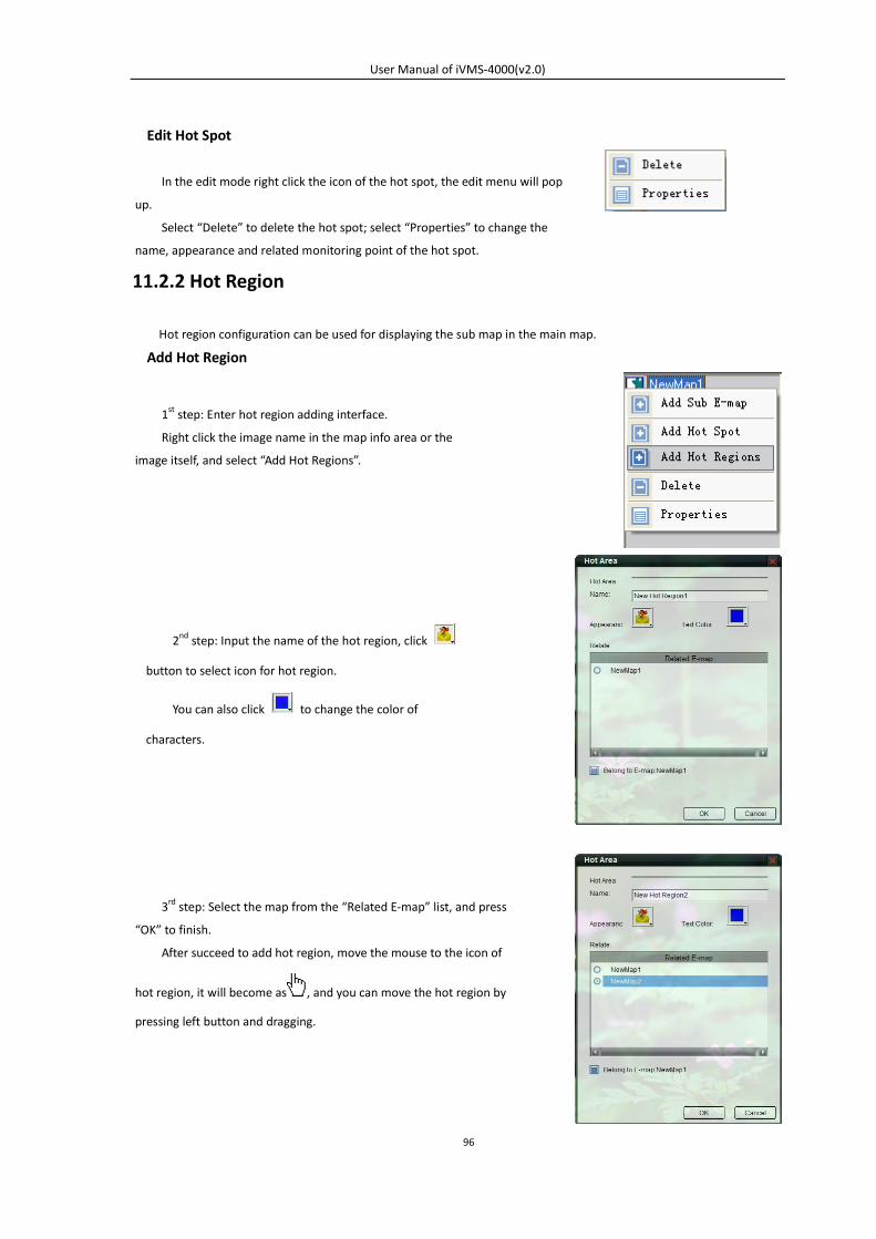
User Manual of iVMS-4000(v2.0)
96
Edit Hot Spot
11.2.2 Hot Region
Hot region configuration can be used for displaying the sub map in the main map.
Add Hot Region
In the edit mode right click the icon of the hot spot, the edit menu will pop
up.
Select “Delete” to delete the hot spot; select “Properties” to change the
name, appearance and related monitoring point of the hot spot.
1st step: Enter hot region adding interface.
Right click the image name in the map info area or the
image itself, and select “Add Hot Regions”.
2nd step: Input the name of the hot region, click
button to select icon for hot region.
You can also click to change the color of
characters.
3rd step: Select the map from the “Related E-map” list, and press
“OK” to finish.
After succeed to add hot region, move the mouse to the icon of
hot region, it will become as , and you can move the hot region by
pressing left button and dragging.
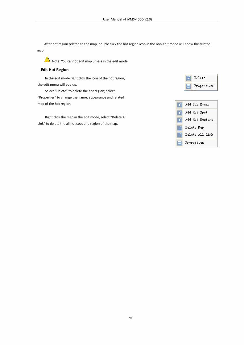
User Manual of iVMS-4000(v2.0)
97
After hot region related to the map, double click the hot region icon in the non-edit mode will show the related
map.
Note: You cannot edit map unless in the edit mode.
Edit Hot Region
In the edit mode right click the icon of the hot region,
the edit menu will pop up.
Select “Delete” to delete the hot region; select
“Properties” to change the name, appearance and related
map of the hot region.
Right click the map in the edit mode, select “Delete All
Link” to delete the all hot spot and region of the map.
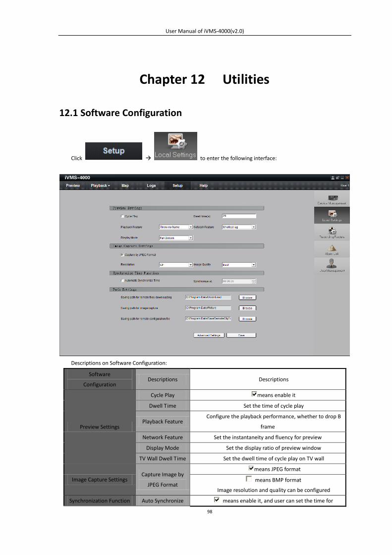
User Manual of iVMS-4000(v2.0)
98
Chapter 12 Utilities
12.1 Software Configuration
Click to enter the following interface:
Descriptions on Software Configuration:
Software
Configuration Descriptions Descriptions
Preview Settings
Cycle Play means enable it
Dwell Time Set the time of cycle play
Playback Feature Configure the playback performance, whether to drop B
frame
Network Feature Set the instantaneity and fluency for preview
Display Mode Set the display ratio of preview window
TV Wall Dwell Time Set the dwell time of cycle play on TV wall
Image Capture Settings Capture Image by
JPEG Format
means JPEG format
means BMP format
Image resolution and quality can be configured
Synchronization Function Auto Synchronize means enable it, and user can set the time for
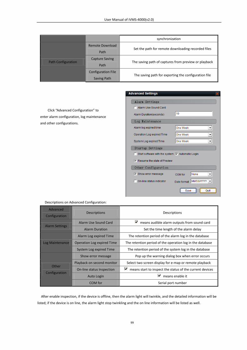
User Manual of iVMS-4000(v2.0)
99
synchronization
Path Configuration
Remote Download
Path Set the path for remote downloading recorded files
Capture Saving
Path The saving path of captures from preview or playback
Configuration File
Saving Path The saving path for exporting the configuration file
Descriptions on Advanced Configuration:
Advanced
Configuration Descriptions Descriptions
Alarm Settings Alarm Use Sound Card means audible alarm outputs from sound card
Alarm Duration Set the time length of the alarm delay
Log Maintenance
Alarm Log expired Time The retention period of the alarm log in the database
Operation Log expired Time The retention period of the operation log in the database
System Log expired Time The retention period of the system log in the database
Other
Configuration
Show error message Pop up the warning dialog box when error occurs
Playback on second monitor Select two screen display for e-map or remote playback
On-line status Inspection means start to inspect the status of the current devices
Auto Login means enable it
COM for Serial port number
After enable inspection, if the device is offline, then the alarm light will twinkle, and the detailed information will be
listed; if the device is on line, the alarm light stop twinkling and the on line information will be listed as well.
Click “Advanced Configuration” to
enter alarm configuration, log maintenance
and other configurations.
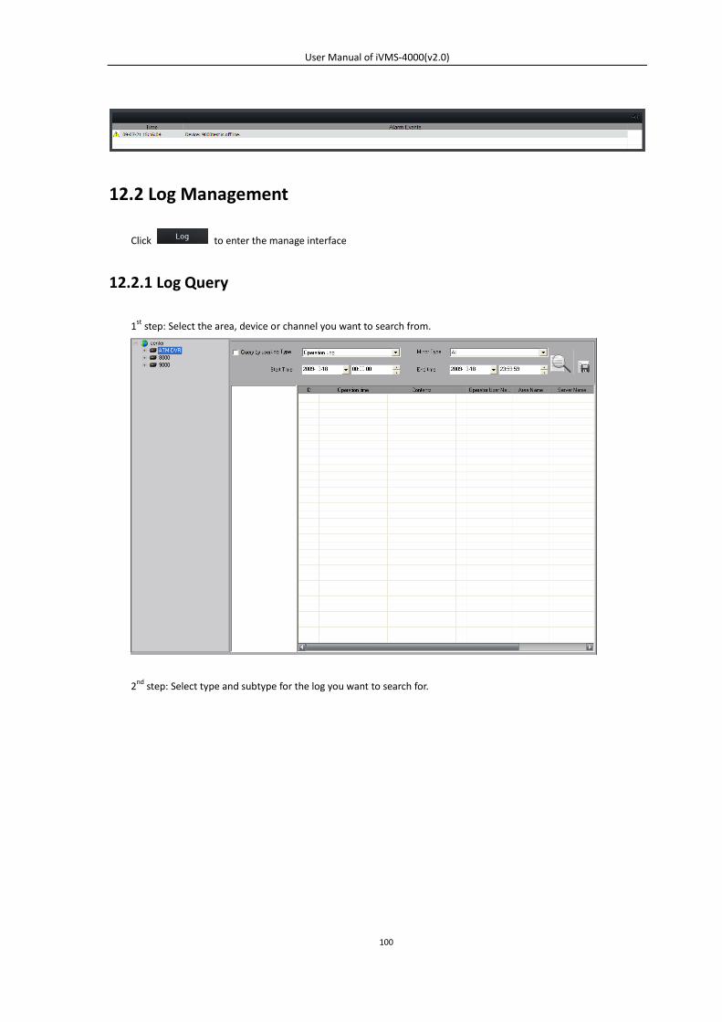
User Manual of iVMS-4000(v2.0)
100
12.2 Log Management
Click to enter the manage interface
12.2.1 Log Query
1st step: Select the area, device or channel you want to search from.
2nd step: Select type and subtype for the log you want to search for.
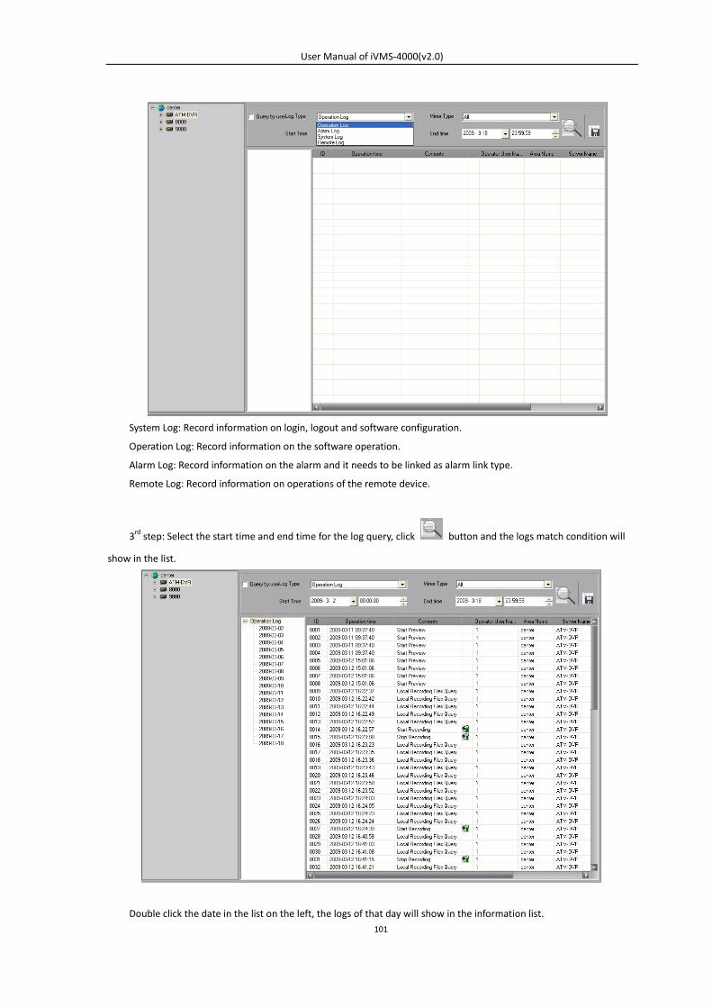
User Manual of iVMS-4000(v2.0)
101
System Log: Record information on login, logout and software configuration.
Operation Log: Record information on the software operation.
Alarm Log: Record information on the alarm and it needs to be linked as alarm link type.
Remote Log: Record information on operations of the remote device.
3rd step: Select the start time and end time for the log query, click button and the logs match condition will
show in the list.
Double click the date in the list on the left, the logs of that day will show in the information list.
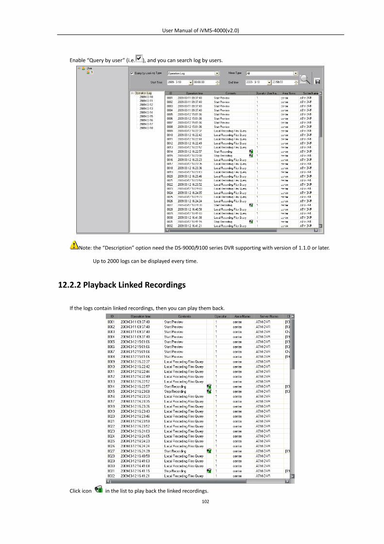
User Manual of iVMS-4000(v2.0)
102
Enable “Query by user” (i.e. ), and you can search log by users.
Note: the “Description” option need the DS-9000/9100 series DVR supporting with version of 1.1.0 or later.
Up to 2000 logs can be displayed every time.
12.2.2 Playback Linked Recordings
If the logs contain linked recordings, then you can play them back.
Click icon in the list to play back the linked recordings.
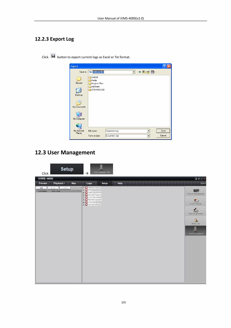
User Manual of iVMS-4000(v2.0)
103
12.2.3 Export Log
Click button to export current logs as Excel or Txt format.
12.3 User Management
Click
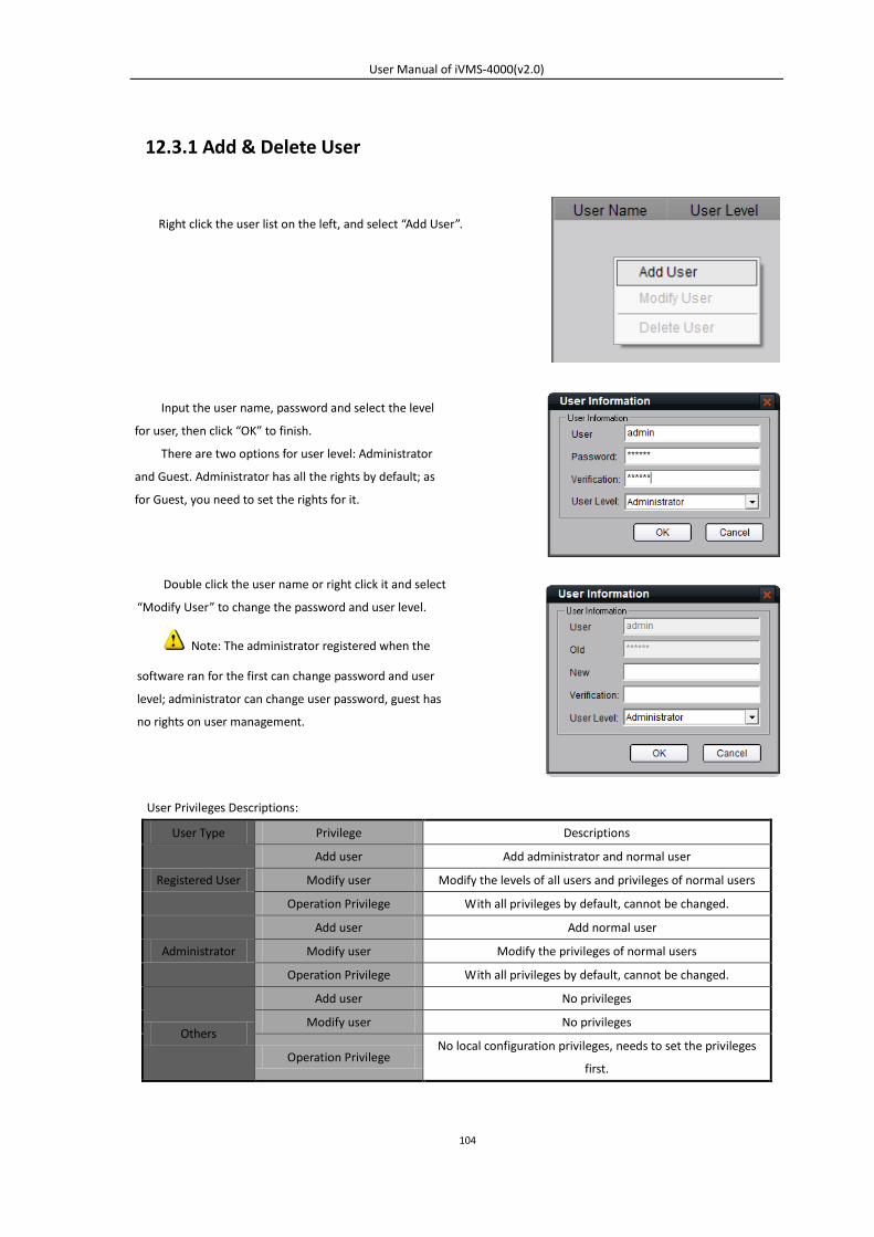
User Manual of iVMS-4000(v2.0)
104
12.3.1 Add & Delete User
User Privileges Descriptions:
User Type Privilege Descriptions
Registered User
Add user Add administrator and normal user
Modify user Modify the levels of all users and privileges of normal users
Operation Privilege With all privileges by default, cannot be changed.
Administrator
Add user Add normal user
Modify user Modify the privileges of normal users
Operation Privilege With all privileges by default, cannot be changed.
Others
Add user No privileges
Modify user No privileges
Operation Privilege No local configuration privileges, needs to set the privileges
first.
Right click the user list on the left, and select “Add User”.
Input the user name, password and select the level
for user, then click “OK” to finish.
There are two options for user level: Administrator
and Guest. Administrator has all the rights by default; as
for Guest, you need to set the rights for it.
Double click the user name or right click it and select
“Modify User” to change the password and user level.
Note: The administrator registered when the
software ran for the first can change password and user
level; administrator can change user password, guest has
no rights on user management.
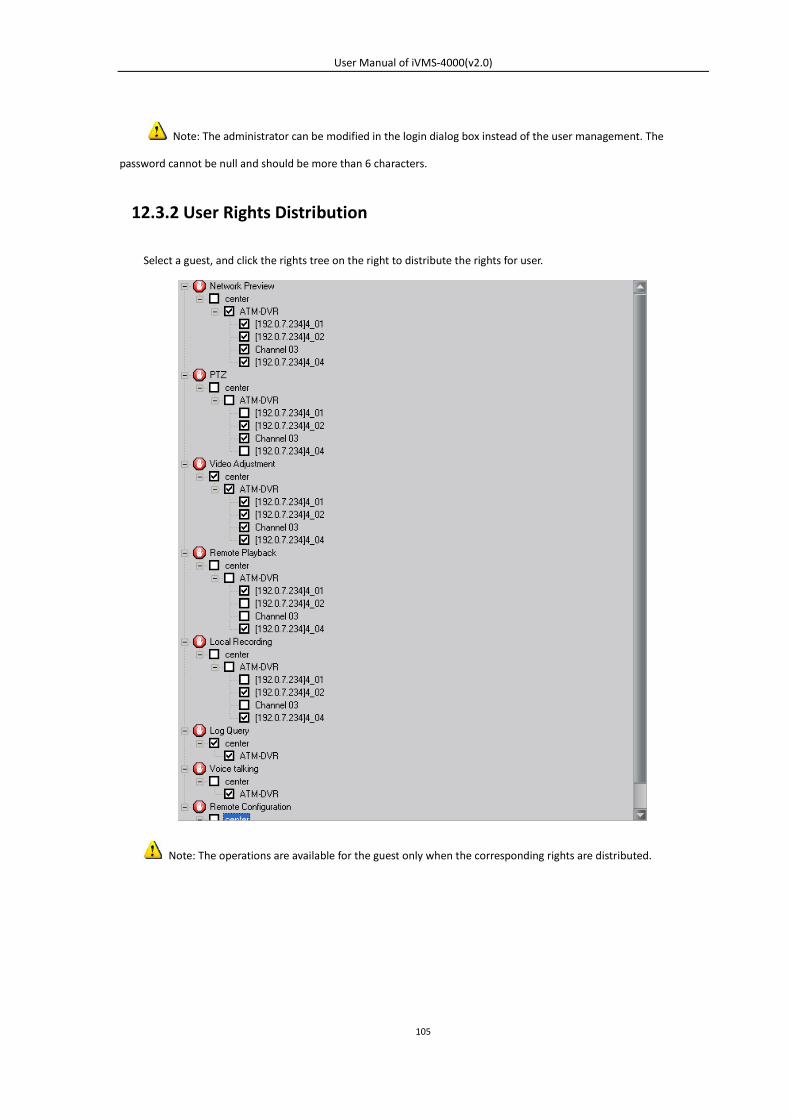
User Manual of iVMS-4000(v2.0)
105
Note: The administrator can be modified in the login dialog box instead of the user management. The
password cannot be null and should be more than 6 characters.
12.3.2 User Rights Distribution
Select a guest, and click the rights tree on the right to distribute the rights for user.
Note: The operations are available for the guest only when the corresponding rights are distributed.


![iVMS-4200 Part 3 Device Groups &Live View › sites › default › files › how...Right Click Menu •Right click a live image for pop-up menu [1] •Capture [2] stores snapshot](https://img.pdfslide.us/doc/110x75/5f03db087e708231d40b194c/ivms-4200-part-3-device-groups-live-view-a-sites-a-default-a-files-a.jpg)