Embed Size (px)
Citation preview
iVMS-2000
Hybrid PC-DVR User Manual
V2.0.1
2009-9
iVMS-2000 User Manual
I
Thank you for purchasing our product. If there is any question or request, please feel free to contact us.
This Manual is for iVMS-2000 Hybrid PC-DVR Software. Please kindly notice that NOT all of the iVMS-2000 software version
supports IP camera connection. This manual may contain several technically incorrect places or printing
errors, and the content is subject to change without notice. The updates will be added into the new version of this manual, and we will readily improve or update the product or procedure described in the manual.
iVMS-2000 User Manual
II
Index
1 Brief Introduction ................................................................................................................. 1
1.1 iVMS-2000 System Solution ................................................................................. 1
1.2 iVMS-2000 Main Features .................................................................................... 2
2 Install and Uninstall ............................................................................................................. 4
2.1 Installation ................................................................................................................ 4
2.2 Uninstall ................................................................................................................. 11
2.3 Start iVMS-2000 .................................................................................................... 13
3 Main Console ....................................................................................................................... 16
3.1 Menu ....................................................................................................................... 17
3.1.1 System Menu ................................................................................................ 17
3.1.2 View Menu ..................................................................................................... 19
3.1.3 Tool Menu ...................................................................................................... 19
3.1.4 Help Menu ..................................................................................................... 24
3.2 Live preview .......................................................................................................... 25
3.2.1 Live Preview specified camera ................................................................... 25
3.2.2 Live Preview multiple cameras ................................................................... 26
3.3 Live Preview in Group .......................................................................................... 26
3.3.1 Live Preview Specified Group ..................................................................... 26
3.3.2 Cycle Live Preview of Group ...................................................................... 26
3.4 Operation on Live Preview Windows ................................................................. 26
3.4.1 Quick PTZ Control (Screen PTZ Control) ................................................. 27
3.4.2 Instant Playback ........................................................................................... 27
3.4.3 Digital Zoom .................................................................................................. 27
3.4.4 Snapshot ........................................................................................................ 28
3.4.5 Manual Record .............................................................................................. 28
3.4.6 Stop Live Preview ......................................................................................... 28
3.4.7 Right-Click Menu of Live Preview .............................................................. 28
3.5 Main Buttons ......................................................................................................... 29
3.5.1 Live Preview Layout ..................................................................................... 29
3.5.2 Full Screen Mode ......................................................................................... 29
3.5.3 Stop All Cameras’ Live Preview .................................................................. 29
3.5.4 Start Emergency Record ............................................................................. 30
3.5.5 Enable/Disable Manual Record on All Cameras ...................................... 30
3.5.6 Start Auto Switch ........................................................................................... 30
3.5.7 Enable/Disable Live Audio .......................................................................... 30
3.6 PTZ Control ........................................................................................................... 30
3.6.1 Preset ............................................................................................................. 32
3.6.2 Patrol .............................................................................................................. 33
3.6.3 Pattern ............................................................................................................ 36
iVMS-2000 User Manual
III
3.7 Video Parameters Configuration ........................................................................ 38
3.8 Alarm out manual control .................................................................................... 39
3.9 Alarm information bar ........................................................................................... 41
3.10 Aux Preview .......................................................................................................... 41
4 Playback............................................................................................................................. 43
4.1 Search by time .................................................................................................. 45
4.2 Synchronous Playback .................................................................................... 47
4.2.1 Playback Clips ............................................................................................ 48
4.2.2 Playback Window Control Bar .............................................................. 49
4.2.3 Playback Time Bar .................................................................................... 51
4.3 Backup .................................................................................................................. 52
4.4 Intelligent Playback ......................................................................................... 57
4.5 Section Playback ............................................................................................... 60
4.6 Clips Playback .................................................................................................... 62
4.7 POS Play ............................................................................................................... 64
4.8 Alarm Log Play ................................................................................................... 66
4.9 Picture View ........................................................................................................ 68
5 E-Map ................................................................................................................................... 70
5.1 E-Map Operations ............................................................................................. 71
5.1.1 Map Operation ........................................................................................... 71
5.1.2 Hot Spot Operation .................................................................................. 72
5.1.3 Add map link operation .......................................................................... 74
5.1.4 Alarm spot operation ............................................................................... 75
5.1.5 Map preview operation ........................................................................... 76
6 Configuration ...................................................................................................................... 78
6.1 General Settings ................................................................................................... 79
6.2 Network .................................................................................................................. 81
6.3 Camera Settings ................................................................................................... 83
6.3.1 Add Camera .................................................................................................. 83
6.3.2 Modify Camera Info ...................................................................................... 85
6.3.3 Delete Camera .............................................................................................. 89
6.3.4 Reboot Camera............................................................................................. 89
6.3.5 Enable/Disable Camera ............................................................................... 89
6.4 Group...................................................................................................................... 90
6.4.1 Add Group ..................................................................................................... 90
6.4.2 Modify Group ................................................................................................. 91
6.4.3 Delete Group ................................................................................................. 91
6.5 Record Schedule .................................................................................................. 92
6.5.1 Add Record Schedule .................................................................................. 92
6.5.2 Modify Record Schedule ............................................................................. 94
6.5.3 Delete Record Schedule ............................................................................. 95
6.5.4 Record Schedule Template ......................................................................... 95
6.6 Alarm Linkage ....................................................................................................... 97
6.6.1 Add Alarm Linkage ....................................................................................... 97

iVMS-2000 User Manual
IV
6.6.2 Modify Alarm Linkage ................................................................................. 103
6.6.3 Delete Alarm Linkage ................................................................................. 105
6.7 Peripheral ............................................................................................................ 107
6.7.1 SMS Configuration ..................................................................................... 108
6.7.2 PTZ COM Port Configuration.................................................................... 108
6.7.3 Alarm Box Configuration............................................................................ 108
6.8 User Configuration ............................................................................................. 111
6.9 Others ................................................................................................................... 113
7 Appendix ............................................................................................................................ 116
7.1 Technical Terms .................................................................................................. 116
iVMS-2000 User Manual
1
1 Brief Introduction
iVMS-2000 is a hybrid PCDVR software designed by HIKVISION. It supports full range of
HIKVISION card and IP camera connection, and can be widely used in local & remote surveillance of
supermarkets, stores, districts and residential places, etc.
This user manual describes the function, configuration and operation steps of iVMS-2000 software.
To ensure the properness and stability of software, please kindly refer to the contents below and read
the manual carefully before installation and operation. This user manual can be acquired via your
supplier.
1.1 iVMS-2000 System Solution
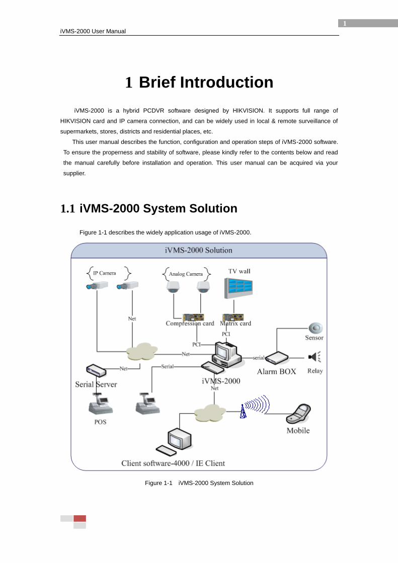
Figure 1-1 describes the widely application usage of iVMS-2000.
Figure 1-1 iVMS-2000 System Solution
iVMS-2000 User Manual
2
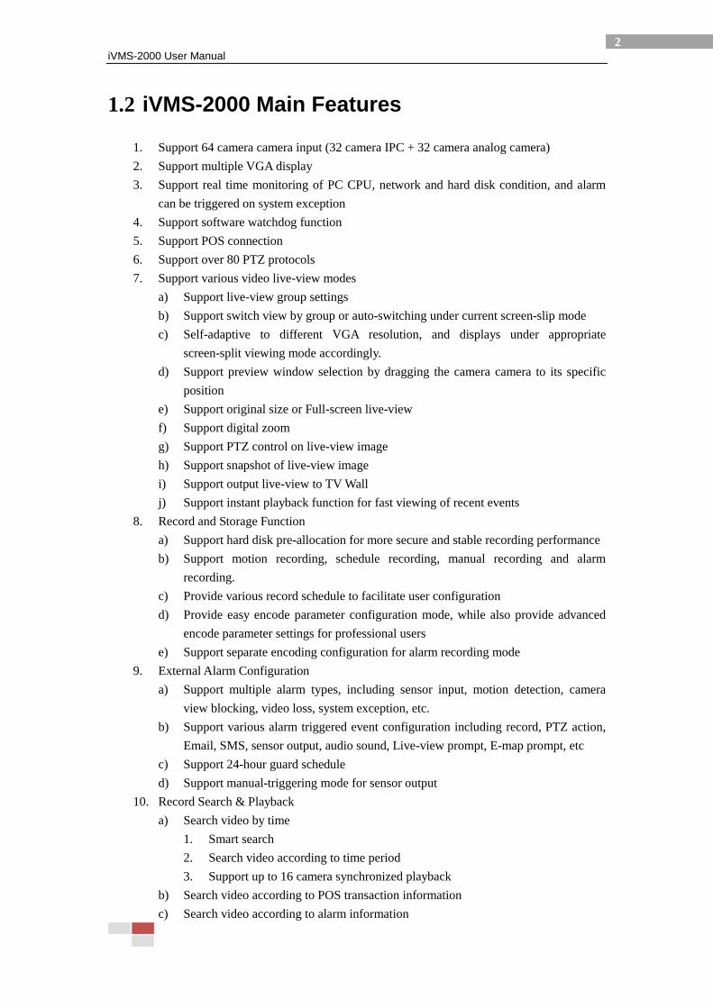
1.2 iVMS-2000 Main Features
1. Support 64 camera camera input (32 camera IPC + 32 camera analog camera)
2. Support multiple VGA display
3. Support real time monitoring of PC CPU, network and hard disk condition, and alarm
can be triggered on system exception
4. Support software watchdog function
5. Support POS connection
6. Support over 80 PTZ protocols
7. Support various video live-view modes
a) Support live-view group settings
b) Support switch view by group or auto-switching under current screen-slip mode
c) Self-adaptive to different VGA resolution, and displays under appropriate
screen-split viewing mode accordingly.
d) Support preview window selection by dragging the camera camera to its specific
position
e) Support original size or Full-screen live-view
f) Support digital zoom
g) Support PTZ control on live-view image
h) Support snapshot of live-view image
i) Support output live-view to TV Wall
j) Support instant playback function for fast viewing of recent events
8. Record and Storage Function
a) Support hard disk pre-allocation for more secure and stable recording performance
b) Support motion recording, schedule recording, manual recording and alarm
recording.
c) Provide various record schedule to facilitate user configuration
d) Provide easy encode parameter configuration mode, while also provide advanced
encode parameter settings for professional users
e) Support separate encoding configuration for alarm recording mode
9. External Alarm Configuration
a) Support multiple alarm types, including sensor input, motion detection, camera
view blocking, video loss, system exception, etc.
b) Support various alarm triggered event configuration including record, PTZ action,
Email, SMS, sensor output, audio sound, Live-view prompt, E-map prompt, etc
c) Support 24-hour guard schedule
d) Support manual-triggering mode for sensor output
10. Record Search & Playback
a) Search video by time
1. Smart search
2. Search video according to time period
3. Support up to 16 camera synchronized playback
b) Search video according to POS transaction information
c) Search video according to alarm information
iVMS-2000 User Manual
3
d) Support video clip playback
e) Display relative alarm info during playback
f) Various playback control functions including Play/Pause/ Stop/ Fast Forward/ Slow
Forward/ Step Forward/ Replay from last minute/ Jump to next minute/ Loop
playback (A-B)
g) Support clip file function (A-B)
h) Support snapshot of playback image
i) Support digital zoom of playback image
j) Support output playback image to TV wall
k) Support Brightness/ Contrast/ Hue/ Saturation adjusting during playback
11. E-map Functions
a) Support adding of surveillance spots, alarm spots and sub map connection
b) Support live-view image display on E-Map
c) Convenient Zoom In/Zoom out / Move operation
12. Network functions
a) Support remote connection via Hikvision Client 4000V2.0 software
b) Support IE client connection
c) Support mobile-phone connection
d) Support DDNS protocol
e) Support Hikvision SADP protocol which can automatically find all the
HIKVISION IPC on-line
iVMS-2000 User Manual
4
2 Install and Uninstall
2.1 Installation
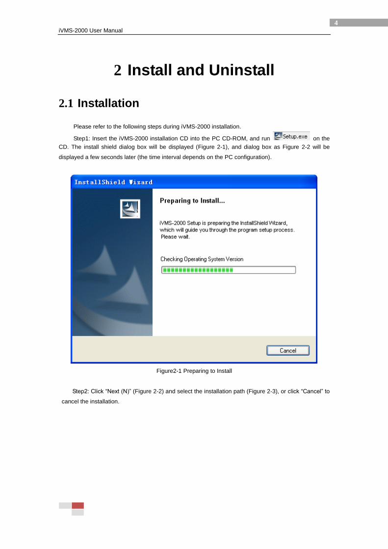
Please refer to the following steps during iVMS-2000 installation.
Step1: Insert the iVMS-2000 installation CD into the PC CD-ROM, and run on the
CD. The install shield dialog box will be displayed (Figure 2-1), and dialog box as Figure 2-2 will be
displayed a few seconds later (the time interval depends on the PC configuration).
Figure2-1 Preparing to Install
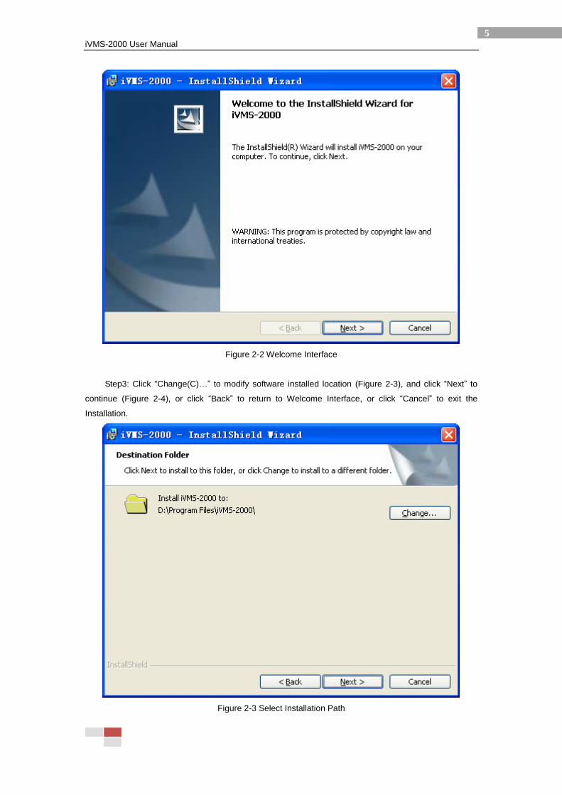
Step2: Click “Next (N)” (Figure 2-2) and select the installation path (Figure 2-3), or click “Cancel” to
cancel the installation.
iVMS-2000 User Manual
5
Figure 2-2 Welcome Interface
Step3: Click “Change(C)…” to modify software installed location (Figure 2-3), and click “Next” to
continue (Figure 2-4), or click “Back” to return to Welcome Interface, or click “Cancel” to exit the
Installation.
Figure 2-3 Select Installation Path
iVMS-2000 User Manual
6
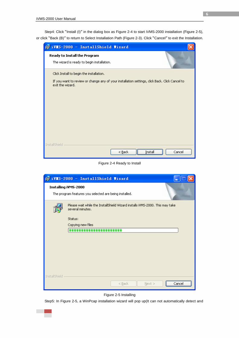
Step4: Click “Install (I)” in the dialog box as Figure 2-4 to start iVMS-2000 installation (Figure 2-5),
or click “Back (B)” to return to Select Installation Path (Figure 2-3). Click “Cancel” to exit the Installation.
Figure 2-4 Ready to Install
Figure 2-5 Installing
Step5: In Figure 2-5, a WinPcap installation wizard will pop up(It can not automatically detect and
iVMS-2000 User Manual
7
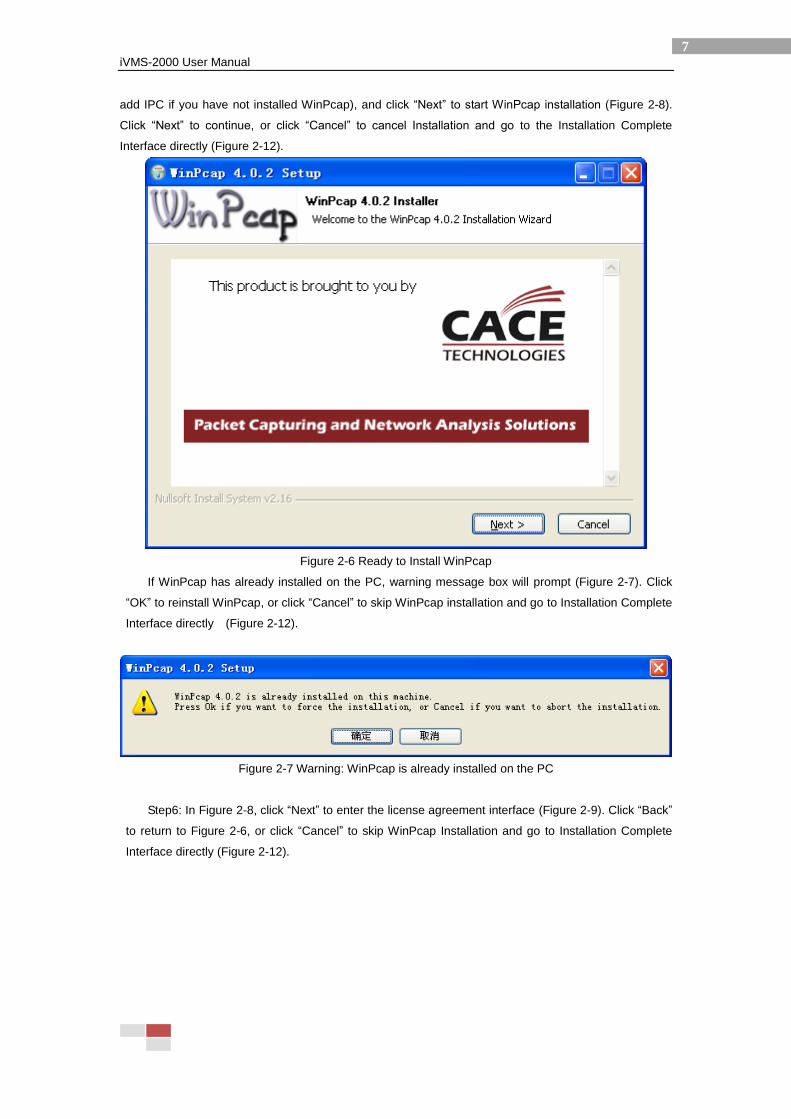
add IPC if you have not installed WinPcap), and click “Next” to start WinPcap installation (Figure 2-8).
Click “Next” to continue, or click “Cancel” to cancel Installation and go to the Installation Complete
Interface directly (Figure 2-12).
Figure 2-6 Ready to Install WinPcap
If WinPcap has already installed on the PC, warning message box will prompt (Figure 2-7). Click
“OK” to reinstall WinPcap, or click “Cancel” to skip WinPcap installation and go to Installation Complete
Interface directly (Figure 2-12).
Figure 2-7 Warning: WinPcap is already installed on the PC
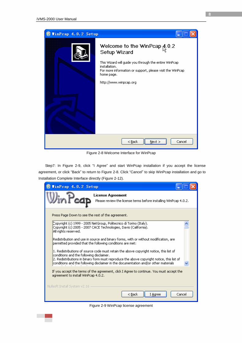
Step6: In Figure 2-8, click “Next” to enter the license agreement interface (Figure 2-9). Click “Back”
to return to Figure 2-6, or click “Cancel” to skip WinPcap Installation and go to Installation Complete
Interface directly (Figure 2-12).
iVMS-2000 User Manual
8
Figure 2-8 Welcome Interface for WinPcap
Step7: In Figure 2-9, click “I Agree” and start WinPcap installation if you accept the license
agreement, or click “Back” to return to Figure 2-8. Click “Cancel” to skip WinPcap installation and go to
Installation Complete Interface directly (Figure 2-12).
Figure 2-9 WinPcap license agreement
iVMS-2000 User Manual
9
Figure 2-10 Installing WinPcap
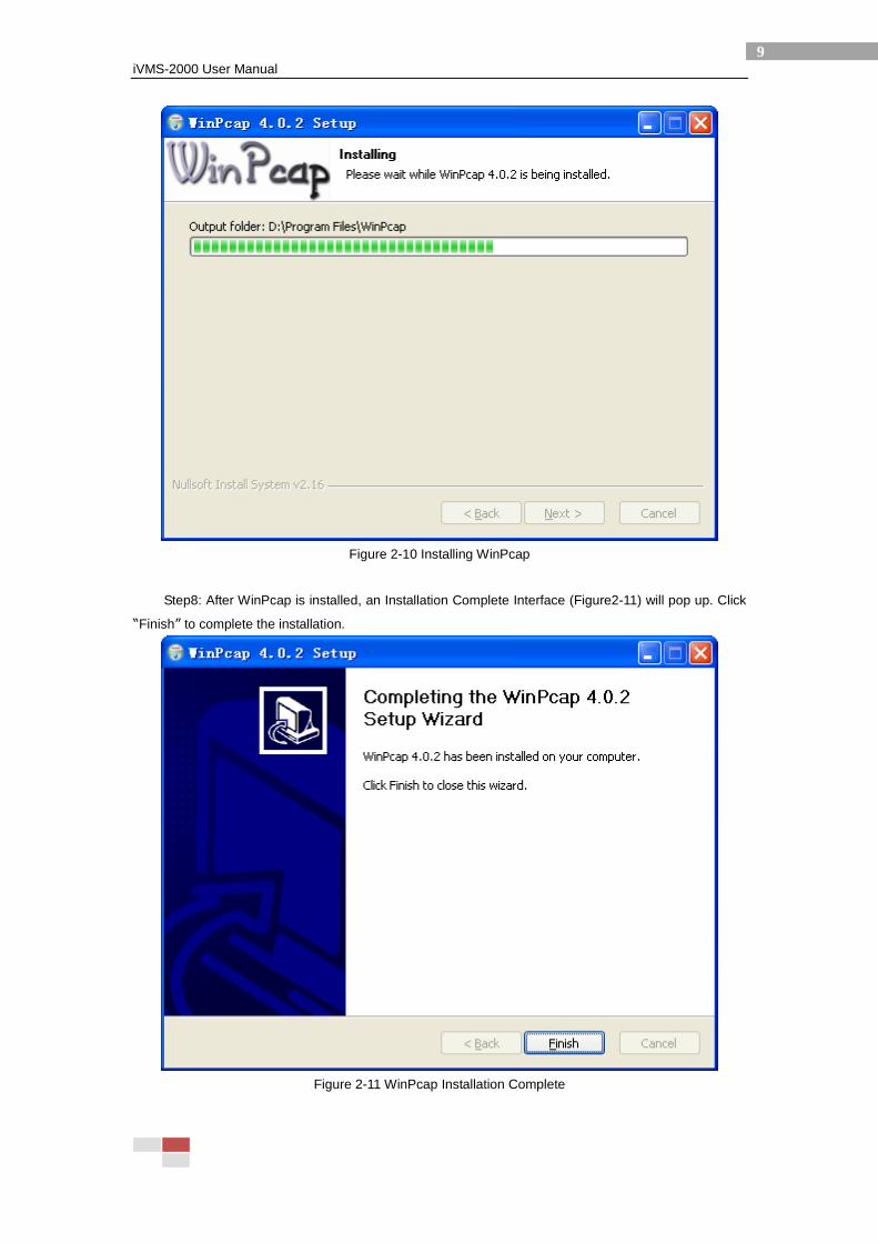
Step8: After WinPcap is installed, an Installation Complete Interface (Figure2-11) will pop up. Click
“Finish” to complete the installation.
Figure 2-11 WinPcap Installation Complete
iVMS-2000 User Manual
10
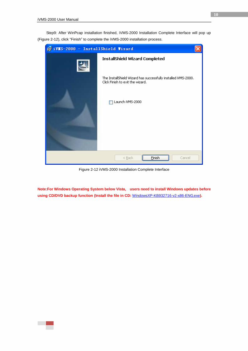
Step9: After WinPcap installation finished, iVMS-2000 Installation Complete Interface will pop up
(Figure 2-12), click “Finish” to complete the iVMS-2000 installation process.
Figure 2-12 iVMS-2000 Installation Complete Interface
Note:For Windows Operating System below Vista, users need to install Windows updates before
using CD/DVD backup function (Install the file in CD: WindowsXP-KB932716-v2-x86-ENG.exe).
iVMS-2000 User Manual
11
2.2 Uninstall
Please refer to the following steps before removing iVMS-2000 systems from personal computers.
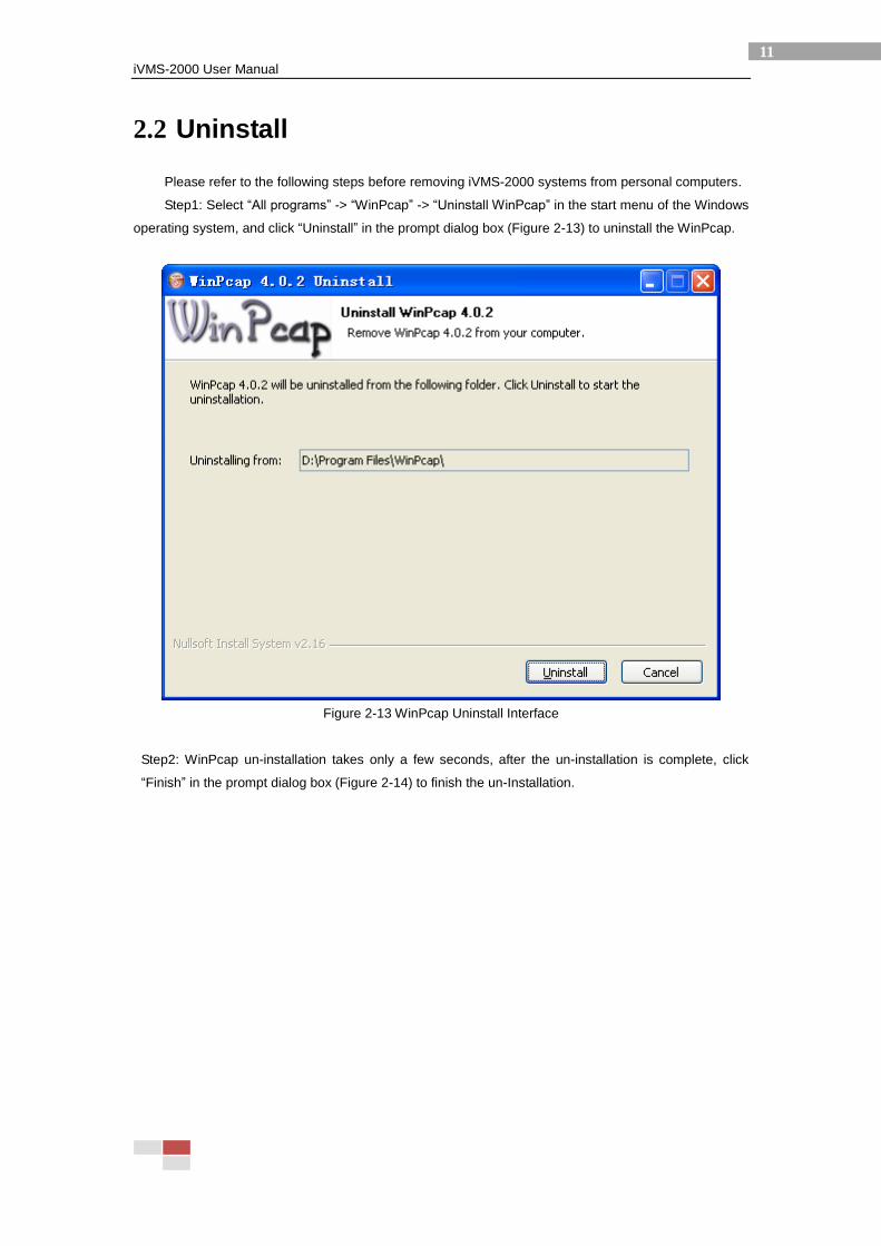
Step1: Select “All programs” -> “WinPcap” -> “Uninstall WinPcap” in the start menu of the Windows
operating system, and click “Uninstall” in the prompt dialog box (Figure 2-13) to uninstall the WinPcap.
Figure 2-13 WinPcap Uninstall Interface
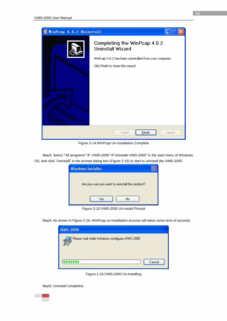
Step2: WinPcap un-installation takes only a few seconds, after the un-installation is complete, click
“Finish” in the prompt dialog box (Figure 2-14) to finish the un-Installation.
iVMS-2000 User Manual
12
Figure 2-14 WinPcap Un-installation Complete
Step3: Select “All programs”” iVMS-2000””Uninstall iVMS-2000” in the start menu of Windows
OS, and click “Uninstall” in the prompt dialog box (Figure 2-15) to start to uninstall the iVMS-2000.
Figure 2-15 iVMS-2000 Un-install Prompt
Step4: As shown in Figure 2-16, WinPcap un-installation process will takes some tens of seconds.
Figure 2-16 iVMS-2000 Un-installing
Step5: Uninstall completed.
iVMS-2000 User Manual
13
2.3 Start iVMS-2000
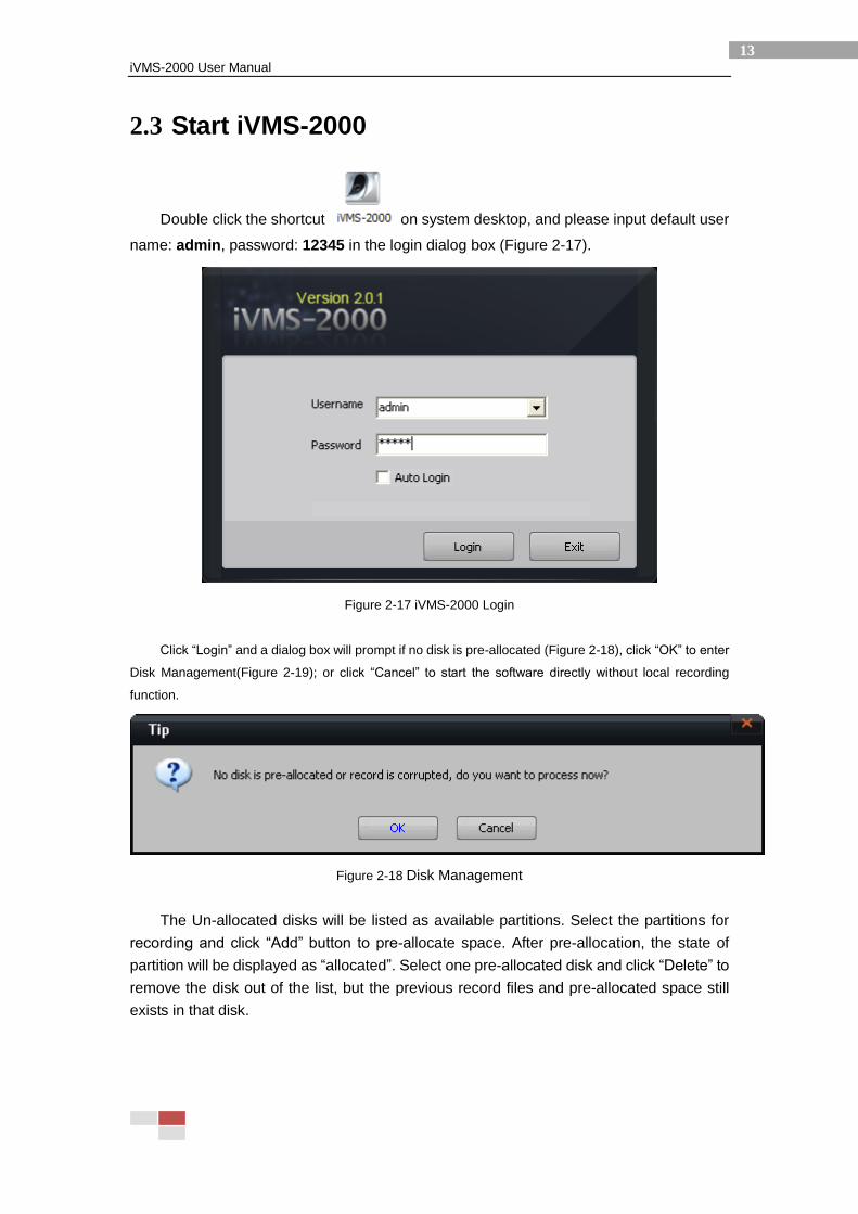
Double click the shortcut on system desktop, and please input default user
name: admin, password: 12345 in the login dialog box (Figure 2-17).
Figure 2-17 iVMS-2000 Login
Click “Login” and a dialog box will prompt if no disk is pre-allocated (Figure 2-18), click “OK” to enter
Disk Management(Figure 2-19); or click “Cancel” to start the software directly without local recording
function.
Figure 2-18 Disk Management
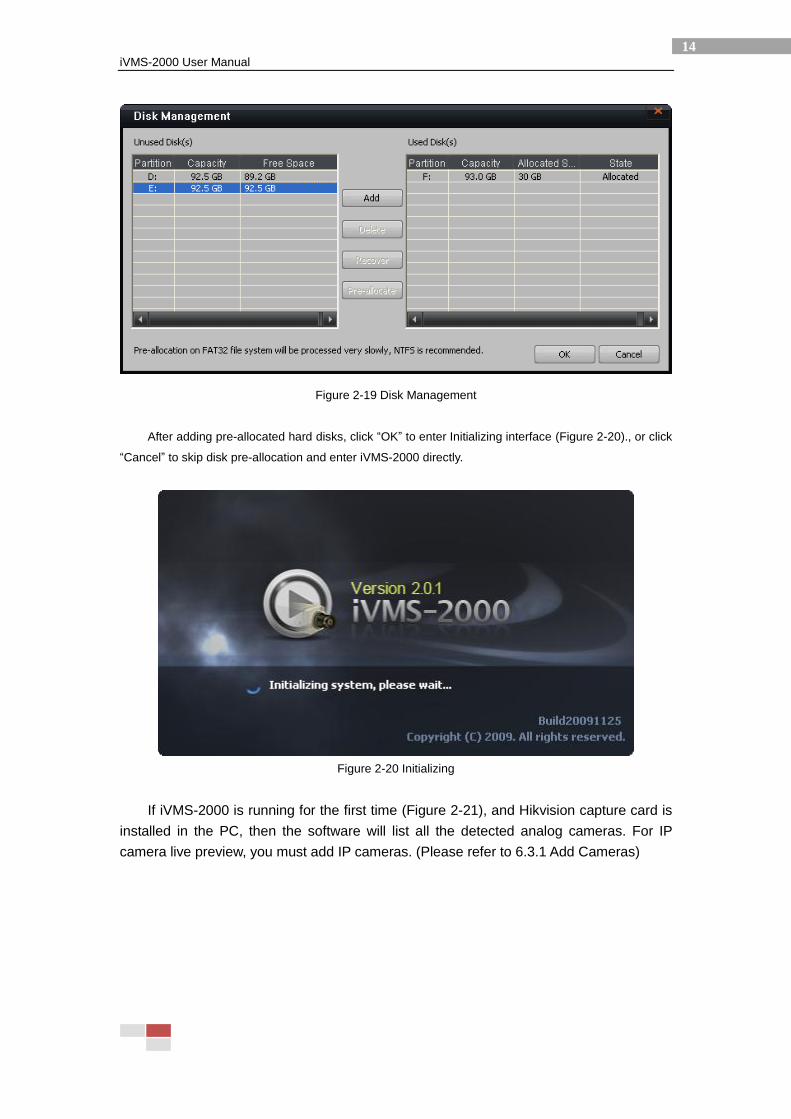
The Un-allocated disks will be listed as available partitions. Select the partitions for
recording and click “Add” button to pre-allocate space. After pre-allocation, the state of
partition will be displayed as “allocated”. Select one pre-allocated disk and click “Delete” to
remove the disk out of the list, but the previous record files and pre-allocated space still
exists in that disk.
iVMS-2000 User Manual
14
Figure 2-19 Disk Management
After adding pre-allocated hard disks, click “OK” to enter Initializing interface (Figure 2-20)., or click
“Cancel” to skip disk pre-allocation and enter iVMS-2000 directly.
Figure 2-20 Initializing
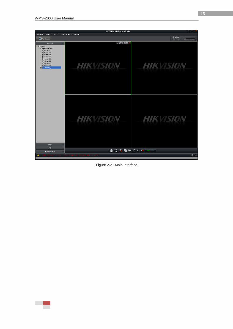
If iVMS-2000 is running for the first time (Figure 2-21), and Hikvision capture card is
installed in the PC, then the software will list all the detected analog cameras. For IP
camera live preview, you must add IP cameras. (Please refer to 6.3.1 Add Cameras)
iVMS-2000 User Manual
15
Figure 2-21 Main Interface
iVMS-2000 User Manual
16
3 Main Console
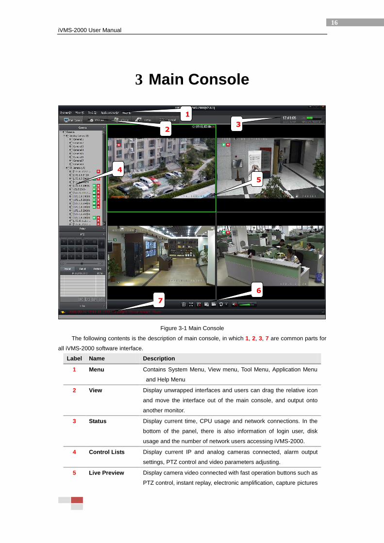
Figure 3-1 Main Console
The following contents is the description of main console, in which 1, 2, 3, 7 are common parts for
all iVMS-2000 software interface.
Label Name Description
1 Menu Contains System Menu, View menu, Tool Menu, Application Menu
and Help Menu
2 View Display unwrapped interfaces and users can drag the relative icon
and move the interface out of the main console, and output onto
another monitor.
3 Status Display current time, CPU usage and network connections. In the
bottom of the panel, there is also information of login user, disk
usage and the number of network users accessing iVMS-2000.
4 Control Lists Display current IP and analog cameras connected, alarm output
settings, PTZ control and video parameters adjusting.
5 Live Preview Display camera video connected with fast operation buttons such as
PTZ control, instant replay, electronic amplification, capture pictures
1
2
3
4
5
6
7
iVMS-2000 User Manual
17
and record, etc.
6 Control Icons Control the whole live preview area, including window-split mode,
full screen, emergency record, manual record and auto switch.
7 Alarm Info Display current alarm information in real time, including the
occurrence time of alarm, alarm source, alarm type. You could get
more alarm information by clicking the column.
3.1 Menu
The Menu Bar is constituted by System (S), View (V), Tools (T), Application (A), and Help (H) menu
(Figure 3-2).
Figure 3-2 Menu Bar
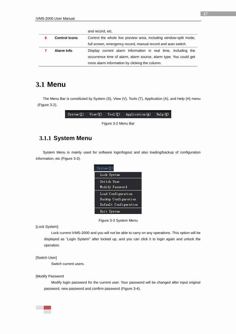
3.1.1 System Menu
System Menu is mainly used for software login/logout and also loading/backup of configuration
information, etc (Figure 3-3).
Figure 3-3 System Menu
[Lock System]
Lock current iVMS-2000 and you will not be able to carry on any operations. This option will be
displayed as “Login System” after locked up, and you can click it to login again and unlock the
operation.
[Switch User]
Switch current users.
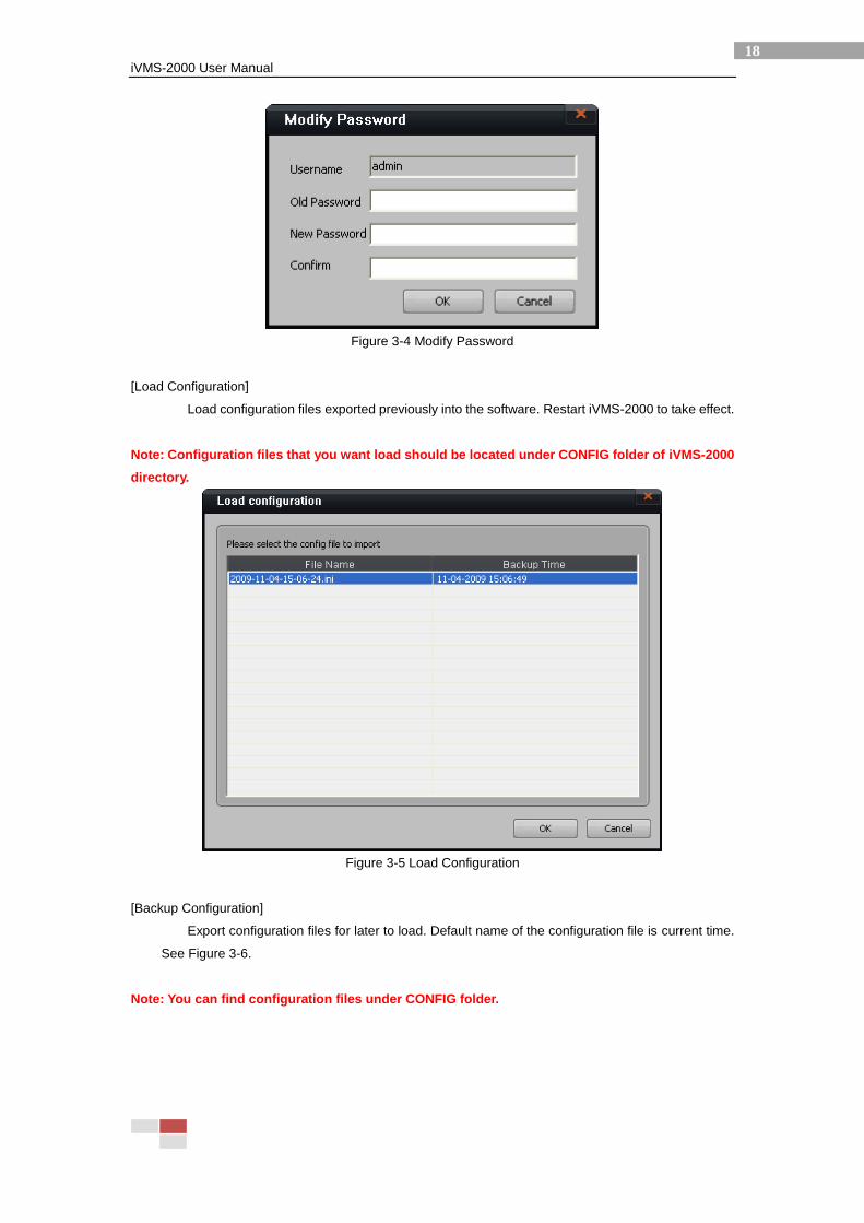
[Modify Password
Modify login password for the current user. Your password will be changed after input original
password, new password and confirm password (Figure 3-4).
iVMS-2000 User Manual
18
Figure 3-4 Modify Password
[Load Configuration]
Load configuration files exported previously into the software. Restart iVMS-2000 to take effect.
Note: Configuration files that you want load should be located under CONFIG folder of iVMS-2000
directory.
Figure 3-5 Load Configuration
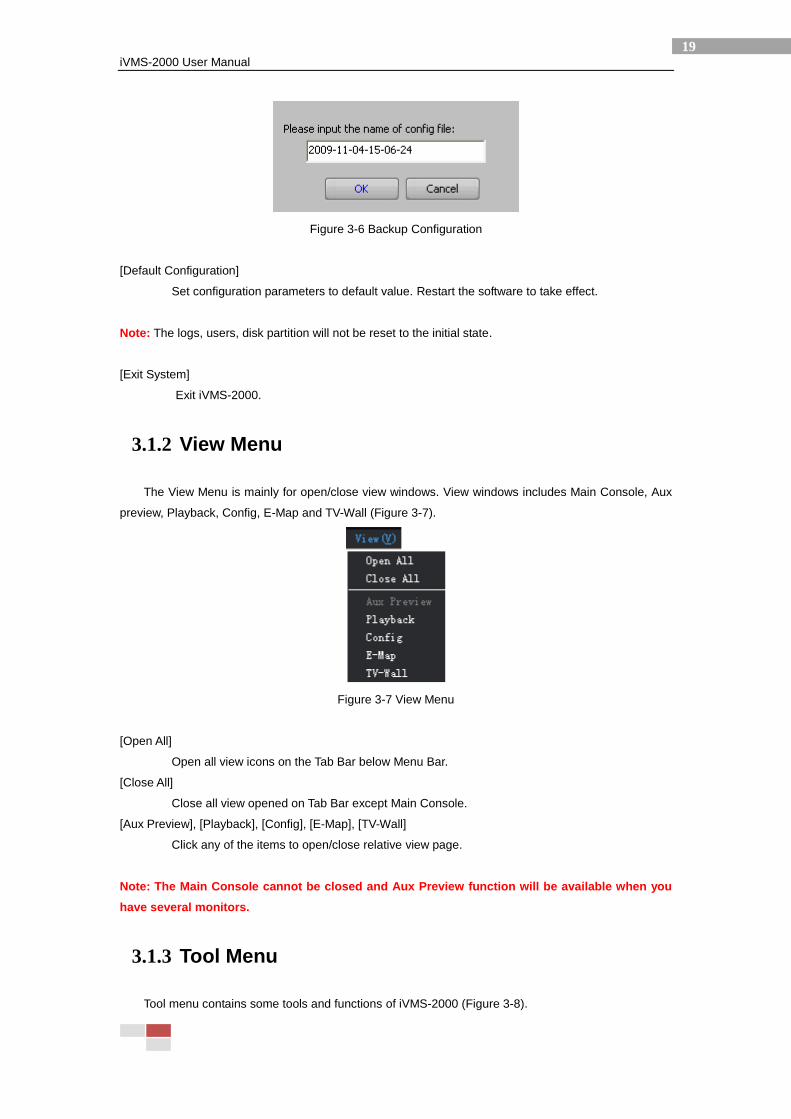
[Backup Configuration]
Export configuration files for later to load. Default name of the configuration file is current time.
See Figure 3-6.
Note: You can find configuration files under CONFIG folder.
iVMS-2000 User Manual
19
Figure 3-6 Backup Configuration
[Default Configuration]
Set configuration parameters to default value. Restart the software to take effect.
Note: The logs, users, disk partition will not be reset to the initial state.
[Exit System]
Exit iVMS-2000.
3.1.2 View Menu
The View Menu is mainly for open/close view windows. View windows includes Main Console, Aux
preview, Playback, Config, E-Map and TV-Wall (Figure 3-7).
Figure 3-7 View Menu
[Open All]
Open all view icons on the Tab Bar below Menu Bar.
[Close All]
Close all view opened on Tab Bar except Main Console.
[Aux Preview], [Playback], [Config], [E-Map], [TV-Wall]
Click any of the items to open/close relative view page.
Note: The Main Console cannot be closed and Aux Preview function will be available when you
have several monitors.
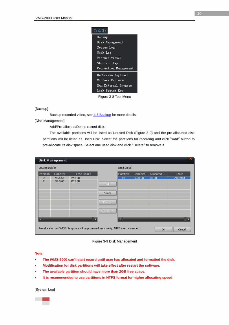
3.1.3 Tool Menu
Tool menu contains some tools and functions of iVMS-2000 (Figure 3-8).
iVMS-2000 User Manual
20
Figure 3-8 Tool Menu
[Backup]
Backup recorded video, see 4.3 Backup for more details.
[Disk Management]
Add/Pre-allocate/Delete record disk.
The available partitions will be listed as Unused Disk (Figure 3-9) and the pre-allocated disk
partitions will be listed as Used Disk. Select the partitions for recording and click “Add” button to
pre-allocate its disk space. Select one used disk and click “Delete” to remove it
Figure 3-9 Disk Management
Note:
The iVMS-2000 can’t start record until user has allocated and formatted the disk.
Modification for disk partitions will take effect after restart the software.
The available partition should have more than 2GB free space.
It is recommended to use partitions in NTFS format for higher allocating speed
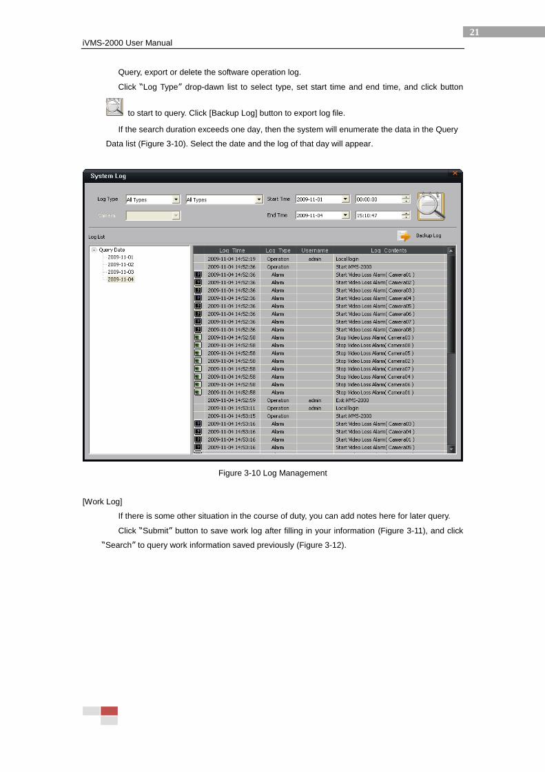
[System Log]
iVMS-2000 User Manual
21
Query, export or delete the software operation log.
Click “Log Type” drop-dawn list to select type, set start time and end time, and click button
to start to query. Click [Backup Log] button to export log file.
If the search duration exceeds one day, then the system will enumerate the data in the Query
Data list (Figure 3-10). Select the date and the log of that day will appear.
Figure 3-10 Log Management
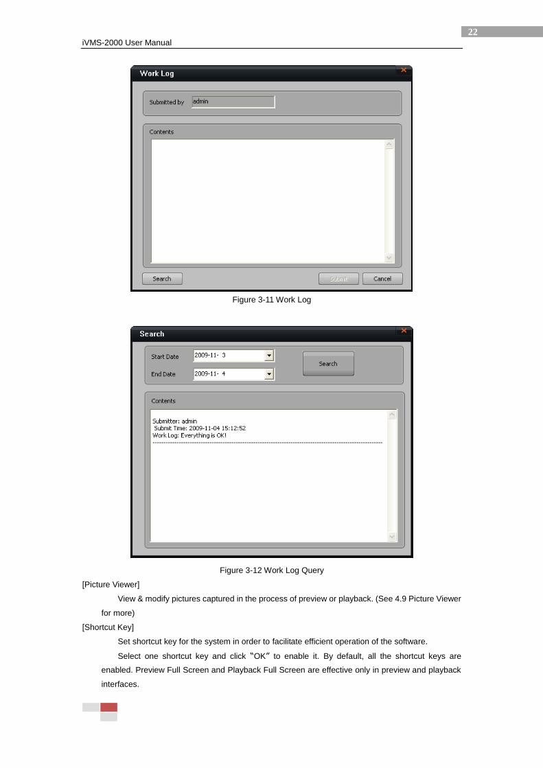
[Work Log]
If there is some other situation in the course of duty, you can add notes here for later query.
Click “Submit” button to save work log after filling in your information (Figure 3-11), and click
“Search” to query work information saved previously (Figure 3-12).
iVMS-2000 User Manual
22
Figure 3-11 Work Log
Figure 3-12 Work Log Query
[Picture Viewer]
View & modify pictures captured in the process of preview or playback. (See 4.9 Picture Viewer
for more)
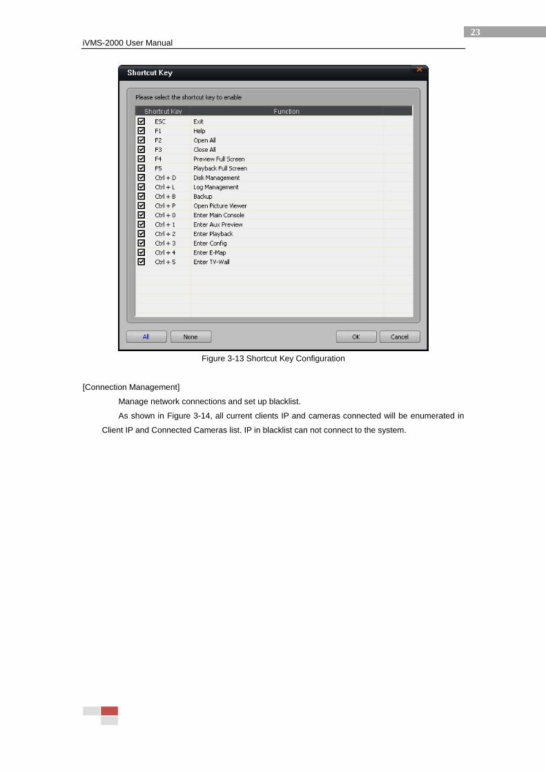
[Shortcut Key]
Set shortcut key for the system in order to facilitate efficient operation of the software.
Select one shortcut key and click “OK” to enable it. By default, all the shortcut keys are
enabled. Preview Full Screen and Playback Full Screen are effective only in preview and playback
interfaces.
iVMS-2000 User Manual
23
Figure 3-13 Shortcut Key Configuration
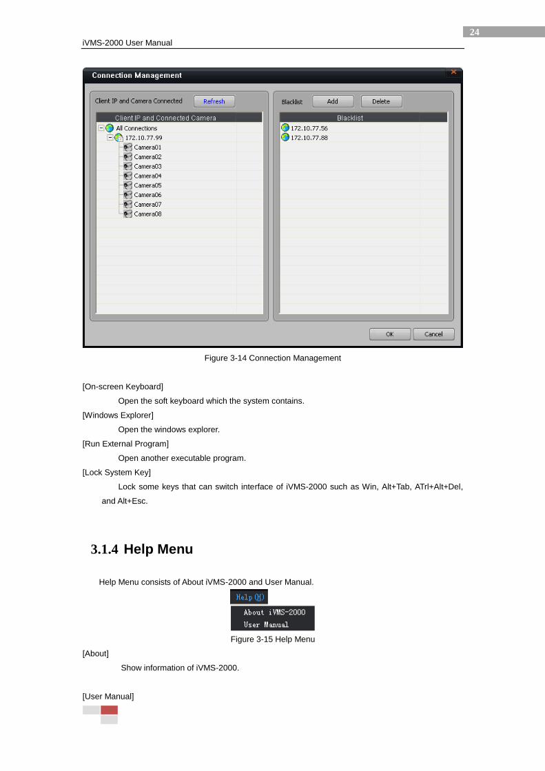
[Connection Management]
Manage network connections and set up blacklist.
As shown in Figure 3-14, all current clients IP and cameras connected will be enumerated in
Client IP and Connected Cameras list. IP in blacklist can not connect to the system.
iVMS-2000 User Manual
24
Figure 3-14 Connection Management
[On-screen Keyboard]
Open the soft keyboard which the system contains.
[Windows Explorer]
Open the windows explorer.
[Run External Program]
Open another executable program.
[Lock System Key]
Lock some keys that can switch interface of iVMS-2000 such as Win, Alt+Tab, ATrl+Alt+Del,
and Alt+Esc.
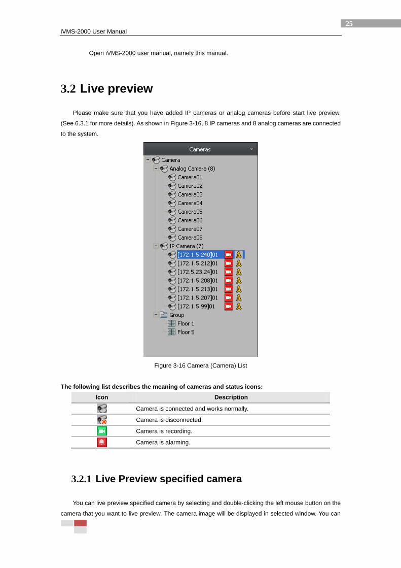
3.1.4 Help Menu
Help Menu consists of About iVMS-2000 and User Manual.
Figure 3-15 Help Menu
[About]
Show information of iVMS-2000.
[User Manual]
iVMS-2000 User Manual
25
Open iVMS-2000 user manual, namely this manual.
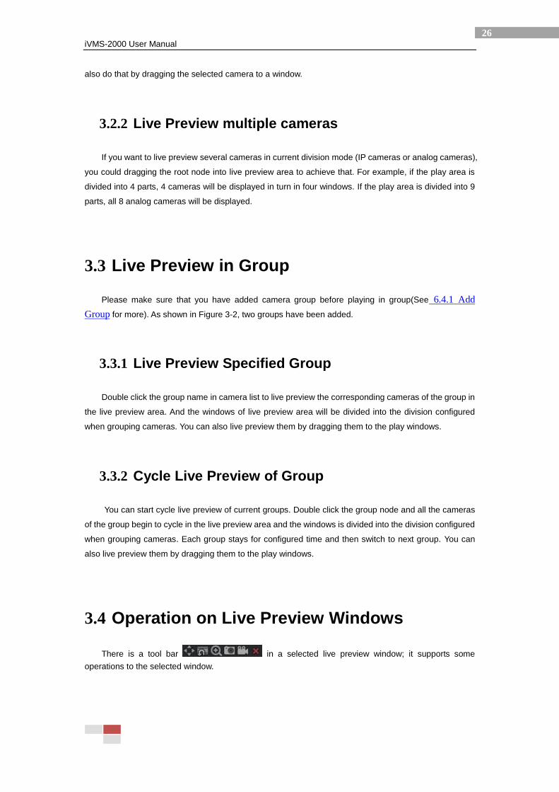
3.2 Live preview
Please make sure that you have added IP cameras or analog cameras before start live preview.
(See 6.3.1 for more details). As shown in Figure 3-16, 8 IP cameras and 8 analog cameras are connected
to the system.
Figure 3-16 Camera (Camera) List
The following list describes the meaning of cameras and status icons:
Icon Description
Camera is connected and works normally.
Camera is disconnected.
Camera is recording.
Camera is alarming.
3.2.1 Live Preview specified camera
You can live preview specified camera by selecting and double-clicking the left mouse button on the
camera that you want to live preview. The camera image will be displayed in selected window. You can
iVMS-2000 User Manual
26
also do that by dragging the selected camera to a window.
3.2.2 Live Preview multiple cameras
If you want to live preview several cameras in current division mode (IP cameras or analog cameras),
you could dragging the root node into live preview area to achieve that. For example, if the play area is
divided into 4 parts, 4 cameras will be displayed in turn in four windows. If the play area is divided into 9
parts, all 8 analog cameras will be displayed.
3.3 Live Preview in Group
Please make sure that you have added camera group before playing in group(See 6.4.1 Add
Group for more). As shown in Figure 3-2, two groups have been added.
3.3.1 Live Preview Specified Group
Double click the group name in camera list to live preview the corresponding cameras of the group in
the live preview area. And the windows of live preview area will be divided into the division configured
when grouping cameras. You can also live preview them by dragging them to the play windows.
3.3.2 Cycle Live Preview of Group
You can start cycle live preview of current groups. Double click the group node and all the cameras
of the group begin to cycle in the live preview area and the windows is divided into the division configured
when grouping cameras. Each group stays for configured time and then switch to next group. You can
also live preview them by dragging them to the play windows.
3.4 Operation on Live Preview Windows
There is a tool bar in a selected live preview window; it supports some
operations to the selected window.
iVMS-2000 User Manual
27
3.4.1 Quick PTZ Control (Screen PTZ Control)
: Control PTZ of camera which the user have operational authority, the button will appear
and 8 direction icons will be showed pointing up, down, left, right, upper left, upper right, lower left,
lower right. An arrow logo will appear when the mouse moved to area identified, click the left mouse
button to control PTZ to the corresponding direction, slide the mouse wheel to zoom in / out. Click the
button again to exit PTZ control.
3.4.2 Instant Playback
: Instant playback about 1 minute record of current camera (Time length depends on the bit rate
of the camera). Click to start instant playback and the tool bar appears . It
includes 6 function buttons: Play, Pause, Stop, Step Backward and Step Forward. Click button stop to
exit instant playback.
Note: The system can not start record and instant playback without disk pre-allocation.
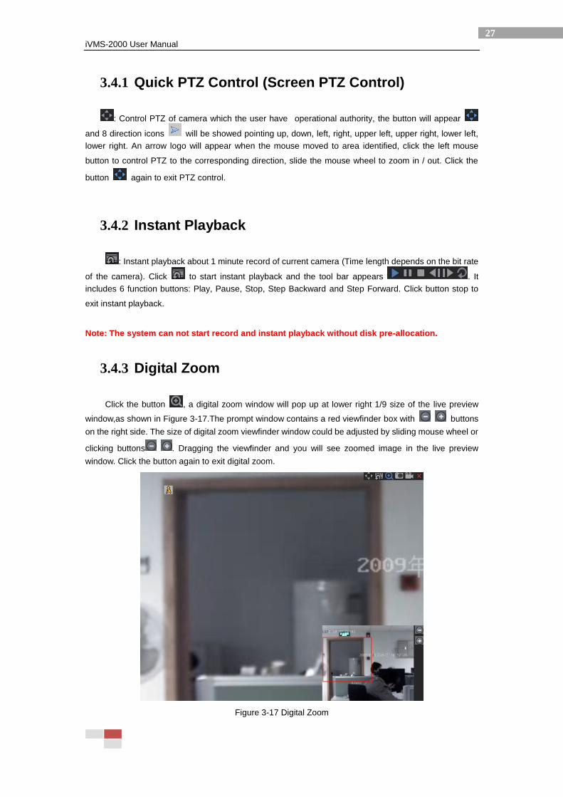
3.4.3 Digital Zoom
Click the button , a digital zoom window will pop up at lower right 1/9 size of the live preview
window,as shown in Figure 3-17.The prompt window contains a red viewfinder box with buttons
on the right side. The size of digital zoom viewfinder window could be adjusted by sliding mouse wheel or
clicking buttons . Dragging the viewfinder and you will see zoomed image in the live preview
window. Click the button again to exit digital zoom.
Figure 3-17 Digital Zoom
iVMS-2000 User Manual
28
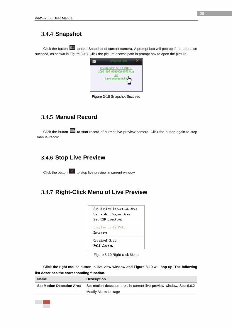
3.4.4 Snapshot
Click the button to take Snapshot of current camera. A prompt box will pop up if the operation
succeed, as shown in Figure 3-18. Click the picture access path in prompt box to open the picture.
Figure 3-18 Snapshot Succeed
3.4.5 Manual Record
Click the button to start record of current live preview camera. Click the button again to stop
manual record.
3.4.6 Stop Live Preview
Click the button to stop live preview in current window.
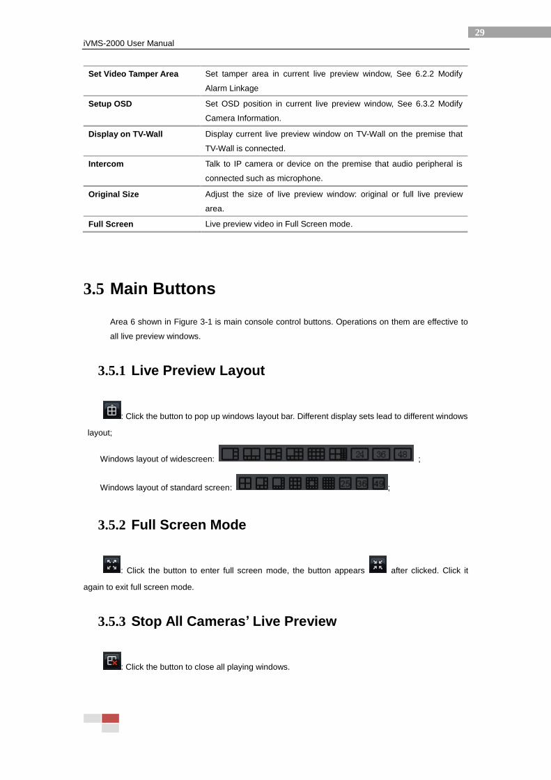
3.4.7 Right-Click Menu of Live Preview
Figure 3-19 Right-click Menu
Click the right mouse button in live view window and Figure 3-19 will pop up. The following
list describes the corresponding function.
Name Description
Set Motion Detection Area Set motion detection area in current live preview window, See 6.6.2
Modify Alarm Linkage
iVMS-2000 User Manual
29
Set Video Tamper Area Set tamper area in current live preview window, See 6.2.2 Modify
Alarm Linkage
Setup OSD Set OSD position in current live preview window, See 6.3.2 Modify
Camera Information.
Display on TV-Wall Display current live preview window on TV-Wall on the premise that
TV-Wall is connected.
Intercom Talk to IP camera or device on the premise that audio peripheral is
connected such as microphone.
Original Size Adjust the size of live preview window: original or full live preview
area.
Full Screen Live preview video in Full Screen mode.
3.5 Main Buttons
Area 6 shown in Figure 3-1 is main console control buttons. Operations on them are effective to
all live preview windows.
3.5.1 Live Preview Layout
: Click the button to pop up windows layout bar. Different display sets lead to different windows
layout;
Windows layout of widescreen: ;
Windows layout of standard screen: ;
3.5.2 Full Screen Mode
: Click the button to enter full screen mode, the button appears after clicked. Click it
again to exit full screen mode.
3.5.3 Stop All Cameras’ Live Preview
: Click the button to close all playing windows.

iVMS-2000 User Manual
30
3.5.4 Start Emergency Record
: Start emergency record for all cameras and will stop automatically, set the record duration in
General Settings interface. See 7.1 System Parameters Configuration for more details. The button
appears after clicked and it will restore to original state until the end of record duration.
3.5.5 Enable/Disable Manual Record on All Cameras
: Start Manual Record for all cameras and it will not stop until click the button again. The
button appears in record duration.
3.5.6 Start Auto Switch
: Click the button to start auto switch by cameras or groups. Select switch mode by clicking
.
Switch by cameras: Start auto switching by cameras according to current live preview layout.
Switching duration can be set in 7.1 System Parameters Configuration.
Switch by groups: See 3.3.2 Cycle live preview of group. It has same function as cycle live preview
of group.
The button appears in switching duration, click it again to exit.
3.5.7 Enable/Disable Live Audio
: Click the button to enable live audio, the icon will appear ;
: After enable live audio, you can adjust volume through the slider.
3.6 PTZ Control
Click in Pulling Control Region in main console to unfold
iVMS-2000 User Manual
31
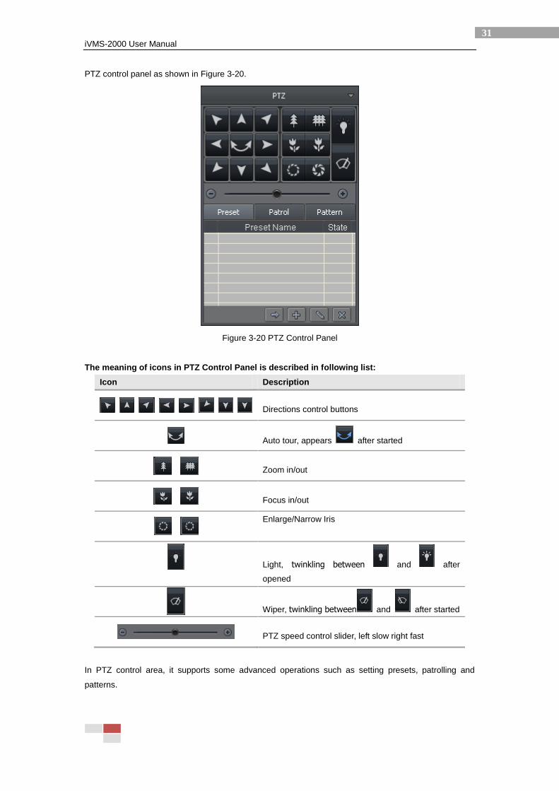
PTZ control panel as shown in Figure 3-20.
Figure 3-20 PTZ Control Panel
The meaning of icons in PTZ Control Panel is described in following list:
Icon Description
Directions control buttons
Auto tour, appears after started
Zoom in/out
Focus in/out
Enlarge/Narrow Iris
Light, twinkling between and after
opened
Wiper, twinkling between and after started
PTZ speed control slider, left slow right fast
In PTZ control area, it supports some advanced operations such as setting presets, patrolling and
patterns.
iVMS-2000 User Manual
32
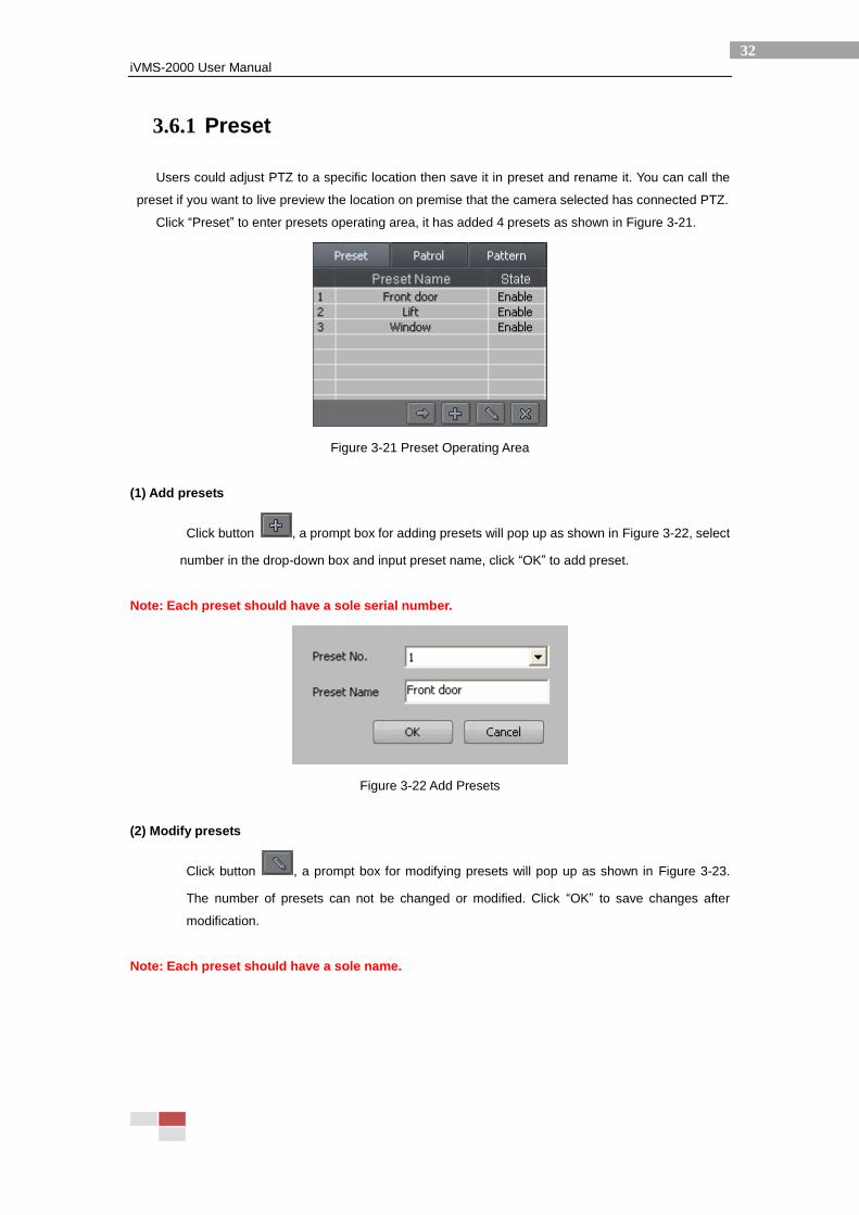
3.6.1 Preset
Users could adjust PTZ to a specific location then save it in preset and rename it. You can call the
preset if you want to live preview the location on premise that the camera selected has connected PTZ.
Click “Preset” to enter presets operating area, it has added 4 presets as shown in Figure 3-21.
Figure 3-21 Preset Operating Area
(1) Add presets
Click button , a prompt box for adding presets will pop up as shown in Figure 3-22, select
number in the drop-down box and input preset name, click “OK” to add preset.
Note: Each preset should have a sole serial number.
Figure 3-22 Add Presets
(2) Modify presets
Click button , a prompt box for modifying presets will pop up as shown in Figure 3-23.
The number of presets can not be changed or modified. Click “OK” to save changes after
modification.
Note: Each preset should have a sole name.
iVMS-2000 User Manual
33
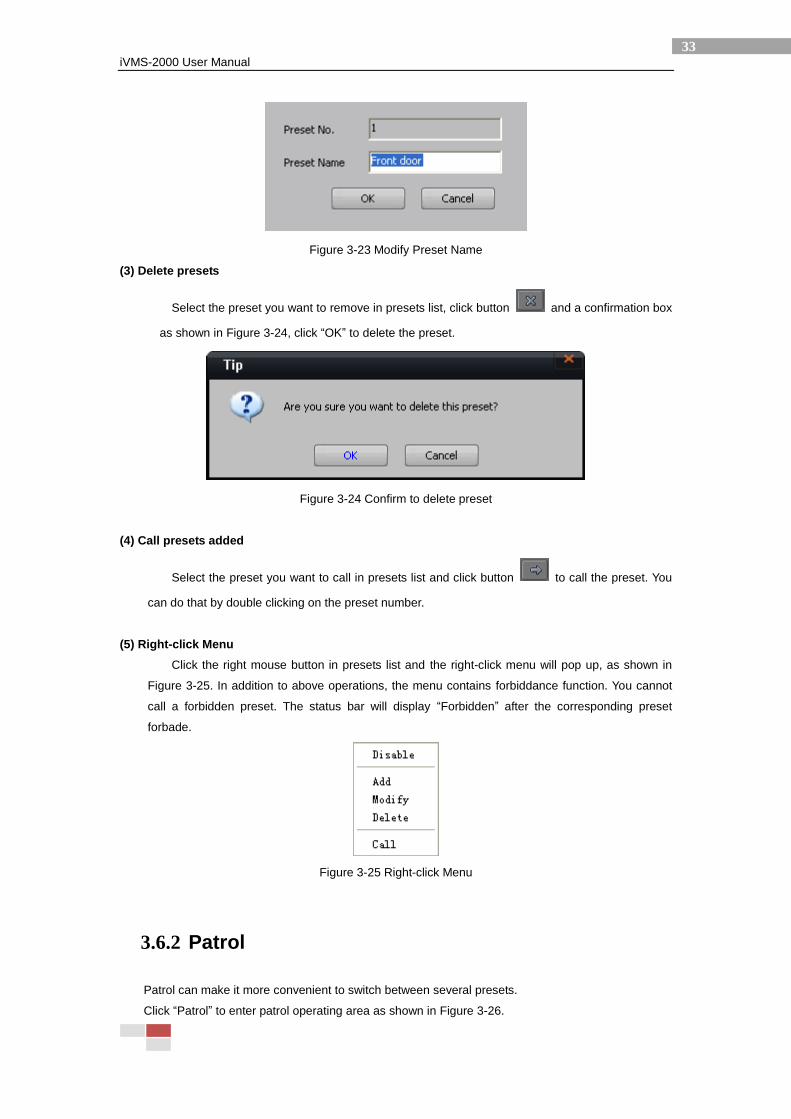
Figure 3-23 Modify Preset Name
(3) Delete presets
Select the preset you want to remove in presets list, click button and a confirmation box
as shown in Figure 3-24, click “OK” to delete the preset.
Figure 3-24 Confirm to delete preset
(4) Call presets added
Select the preset you want to call in presets list and click button to call the preset. You
can do that by double clicking on the preset number.
(5) Right-click Menu
Click the right mouse button in presets list and the right-click menu will pop up, as shown in
Figure 3-25. In addition to above operations, the menu contains forbiddance function. You cannot
call a forbidden preset. The status bar will display “Forbidden” after the corresponding preset
forbade.
Figure 3-25 Right-click Menu
3.6.2 Patrol
Patrol can make it more convenient to switch between several presets.
Click “Patrol” to enter patrol operating area as shown in Figure 3-26.
iVMS-2000 User Manual
34
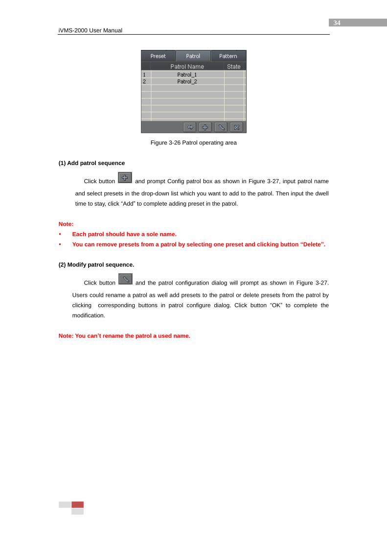
Figure 3-26 Patrol operating area
(1) Add patrol sequence
Click button and prompt Config patrol box as shown in Figure 3-27, input patrol name
and select presets in the drop-down list which you want to add to the patrol. Then input the dwell
time to stay, click “Add” to complete adding preset in the patrol.
Note:
Each patrol should have a sole name.
You can remove presets from a patrol by selecting one preset and clicking button “Delete”.
(2) Modify patrol sequence.
Click button and the patrol configuration dialog will prompt as shown in Figure 3-27.
Users could rename a patrol as well add presets to the patrol or delete presets from the patrol by
clicking corresponding buttons in patrol configure dialog. Click button “OK” to complete the
modification.
Note: You can’t rename the patrol a used name.
iVMS-2000 User Manual
35
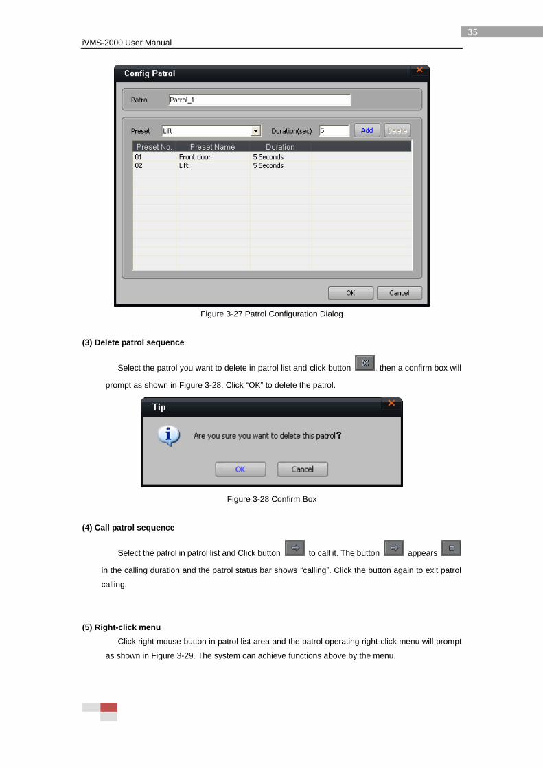
Figure 3-27 Patrol Configuration Dialog
(3) Delete patrol sequence
Select the patrol you want to delete in patrol list and click button , then a confirm box will
prompt as shown in Figure 3-28. Click “OK” to delete the patrol.
Figure 3-28 Confirm Box
(4) Call patrol sequence
Select the patrol in patrol list and Click button to call it. The button appears
in the calling duration and the patrol status bar shows “calling”. Click the button again to exit patrol
calling.
(5) Right-click menu
Click right mouse button in patrol list area and the patrol operating right-click menu will prompt
as shown in Figure 3-29. The system can achieve functions above by the menu.
iVMS-2000 User Manual
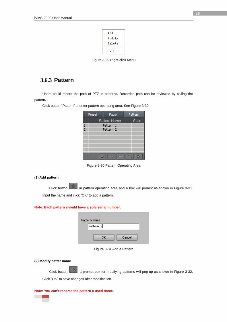
36
Figure 3-29 Right-click Menu
3.6.3 Pattern
Users could record the path of PTZ in patterns. Recorded path can be reviewed by calling the
pattern.
Click button “Pattern” to enter pattern operating area. See Figure 3-30.
Figure 3-30 Pattern Operating Area
(1) Add pattern
Click button in pattern operating area and a box will prompt as shown in Figure 3-31.
Input the name and click “OK” to add a pattern.
Note: Each pattern should have a sole serial number.
Figure 3-31 Add a Pattern
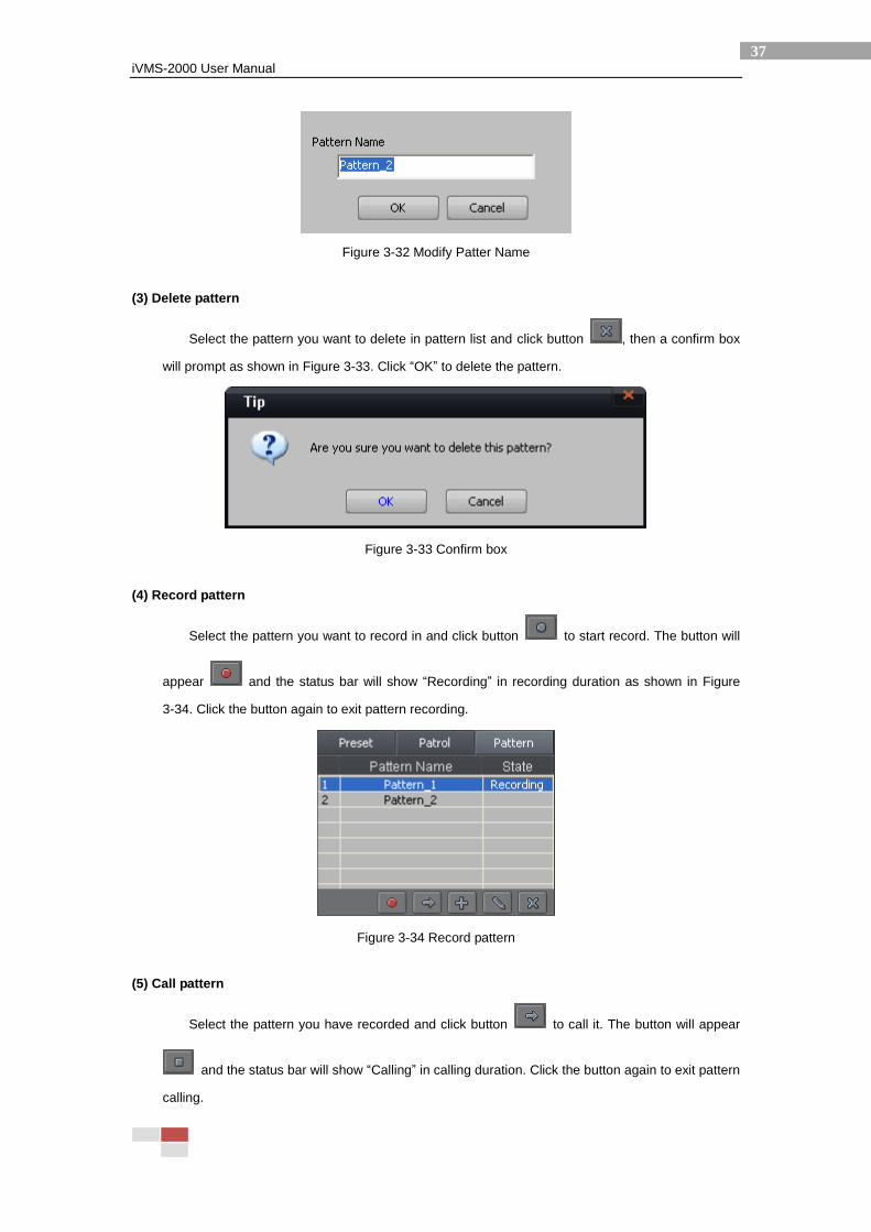
(2) Modify patter name
Click button , a prompt box for modifying patterns will pop up as shown in Figure 3-32.
Click “OK” to save changes after modification.
Note: You can’t rename the pattern a used name.
iVMS-2000 User Manual
37
Figure 3-32 Modify Patter Name
(3) Delete pattern
Select the pattern you want to delete in pattern list and click button , then a confirm box
will prompt as shown in Figure 3-33. Click “OK” to delete the pattern.
Figure 3-33 Confirm box
(4) Record pattern
Select the pattern you want to record in and click button to start record. The button will
appear and the status bar will show “Recording” in recording duration as shown in Figure
3-34. Click the button again to exit pattern recording.
Figure 3-34 Record pattern
(5) Call pattern
Select the pattern you have recorded and click button to call it. The button will appear
and the status bar will show “Calling” in calling duration. Click the button again to exit pattern
calling.
iVMS-2000 User Manual
38
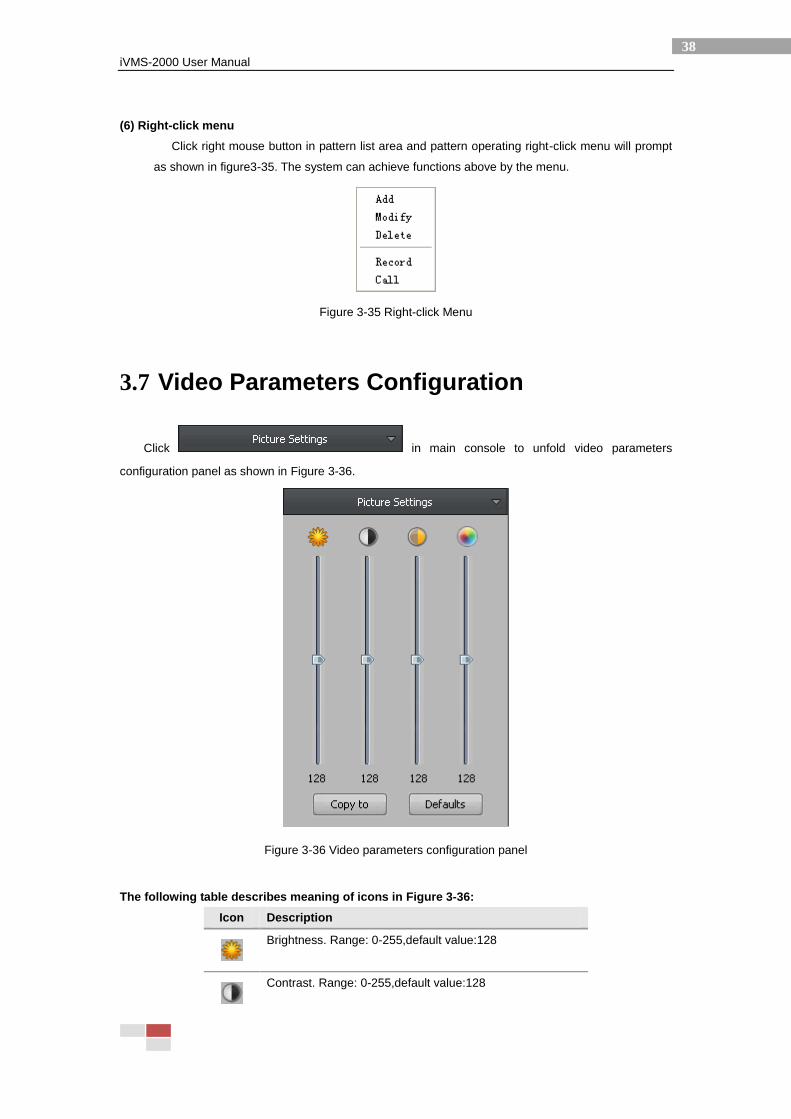
(6) Right-click menu
Click right mouse button in pattern list area and pattern operating right-click menu will prompt
as shown in figure3-35. The system can achieve functions above by the menu.
Figure 3-35 Right-click Menu
3.7 Video Parameters Configuration
Click in main console to unfold video parameters
configuration panel as shown in Figure 3-36.
Figure 3-36 Video parameters configuration panel
The following table describes meaning of icons in Figure 3-36:
Icon Description
Brightness. Range: 0-255,default value:128
Contrast. Range: 0-255,default value:128
iVMS-2000 User Manual
39
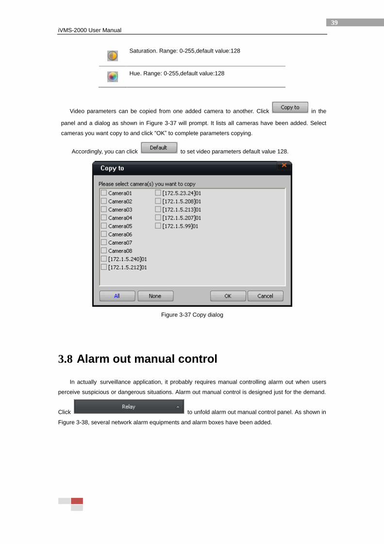
Saturation. Range: 0-255,default value:128
Hue. Range: 0-255,default value:128
Video parameters can be copied from one added camera to another. Click in the
panel and a dialog as shown in Figure 3-37 will prompt. It lists all cameras have been added. Select
cameras you want copy to and click “OK” to complete parameters copying.
Accordingly, you can click to set video parameters default value 128.
Figure 3-37 Copy dialog
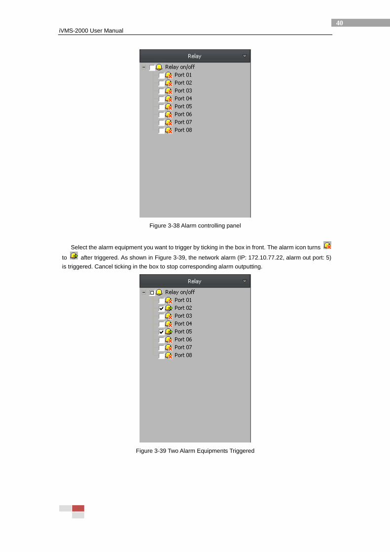
3.8 Alarm out manual control
In actually surveillance application, it probably requires manual controlling alarm out when users
perceive suspicious or dangerous situations. Alarm out manual control is designed just for the demand.
Click to unfold alarm out manual control panel. As shown in
Figure 3-38, several network alarm equipments and alarm boxes have been added.
iVMS-2000 User Manual
40
Figure 3-38 Alarm controlling panel
Select the alarm equipment you want to trigger by ticking in the box in front. The alarm icon turns
to after triggered. As shown in Figure 3-39, the network alarm (IP: 172.10.77.22, alarm out port: 5)
is triggered. Cancel ticking in the box to stop corresponding alarm outputting.
Figure 3-39 Two Alarm Equipments Triggered
iVMS-2000 User Manual
41
3.9 Alarm information bar
When the system receives alarm message, alarm information bar will show red font twinkling with
alarm bell. See Figure 3-40.
Figure 3-40 Alarm information bar
Click alarm information bar to unfold it as shown in Figure 3-41. The list enumerates alarm mode,
occurrence time, alarm source and recording camera. You can reorder these items by clicking
corresponding head column. Click to keep the information bar always visible. Click it again to hide
the alarm information bar.
Figure 3-41 Unfolded Alarm Information Bar
Double click on alarm information enumerated to playback corresponding alarm record in single
playback window mode. The premise is that users have pre-allocated disks for the system.
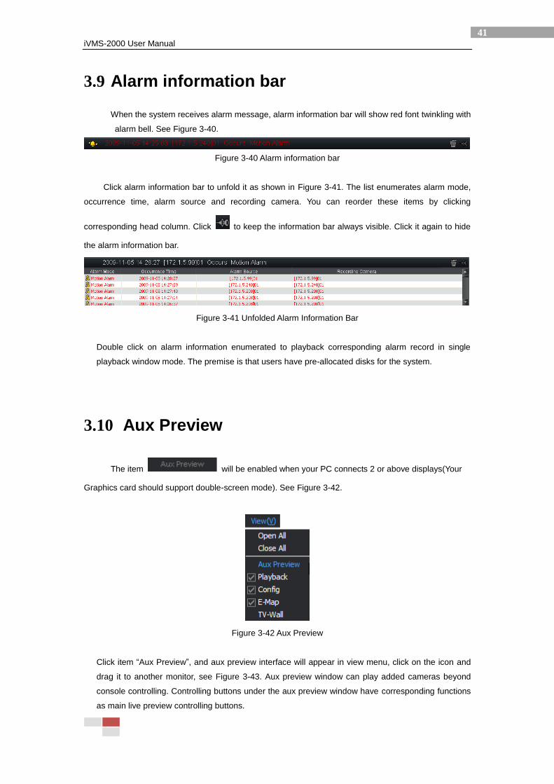
3.10 Aux Preview
The item will be enabled when your PC connects 2 or above displays(Your
Graphics card should support double-screen mode). See Figure 3-42.
Figure 3-42 Aux Preview
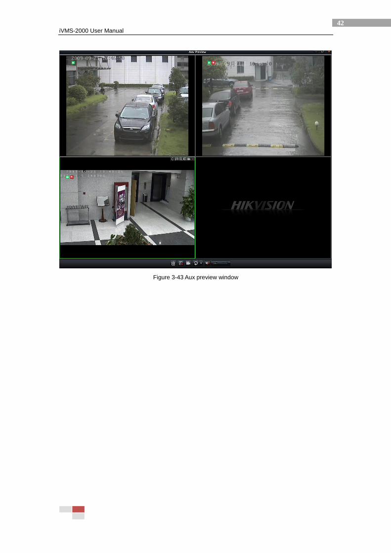
Click item “Aux Preview”, and aux preview interface will appear in view menu, click on the icon and
drag it to another monitor, see Figure 3-43. Aux preview window can play added cameras beyond
console controlling. Controlling buttons under the aux preview window have corresponding functions
as main live preview controlling buttons.
iVMS-2000 User Manual
42
Figure 3-43 Aux preview window
iVMS-2000 User Manual
43
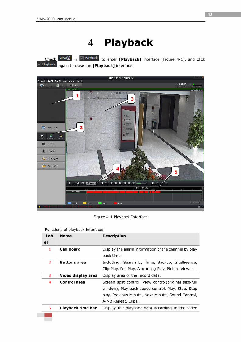
4 Playback
Check in to enter [Playback] interface (Figure 4-1), and click
again to close the [Playback] interface.
Figure 4-1 Playback Interface
Functions of playback interface:
Lab
el
Name Description
1 Call board Display the alarm information of the channel by play
back time
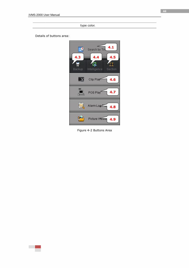
2 Buttons area Including: Search by Time, Backup, Intelligence,
Clip Play, Pos Play, Alarm Log Play, Picture Viewer …
3 Video display area Display area of the record data.
4 Control area Screen split control, View control(original size/full
window), Play back speed control, Play, Stop, Step
play, Previous Minute, Next Minute, Sound Control,
A->B Repeat, Clips…
5 Playback time bar Display the playback data according to the video
3
2
4
1
5
iVMS-2000 User Manual
44
type color.
Details of buttons area:
Figure 4-2 Buttons Area
4.1
1
4.3
1
4.4
1
4.5
1
4.6
1
4.7
1
4.8
1
4.9
1
iVMS-2000 User Manual
45
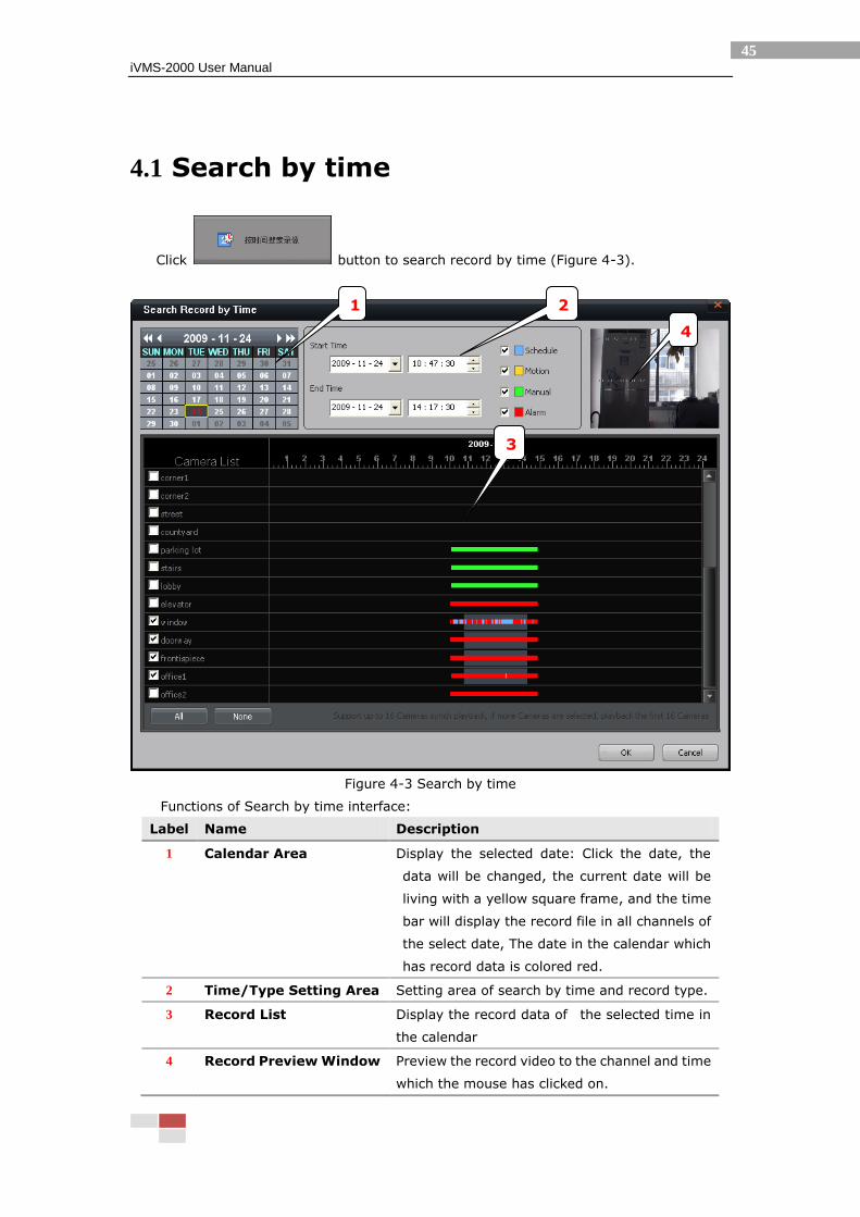
4.1 Search by time
Click button to search record by time (Figure 4-3).
Figure 4-3 Search by time
Functions of Search by time interface:
Label Name Description
1 Calendar Area Display the selected date: Click the date, the
data will be changed, the current date will be
living with a yellow square frame, and the time
bar will display the record file in all channels of
the select date, The date in the calendar which
has record data is colored red.
2 Time/Type Setting Area Setting area of search by time and record type.
3 Record List Display the record data of the selected time in
the calendar
4 Record Preview Window Preview the record video to the channel and time
which the mouse has clicked on.
1 2
3
4
iVMS-2000 User Manual
46
Notes:
The selected time in calendar and the date in the time setting area are equal,
and it is more directly in the calendar.
The record time list can only display the record data in one day.
The record preview window only displays the current selected record data in
the first channel.
Search single-day video data:
1. Set playback time in [Calendar Area] / [Time/Type Setting Area]
2. Set record type in [Time/Type Setting Area] (Selected all default)
3. Select channel in [Record List]
4. Click [OK] button to playback.
Notes: Set the record time, channel by mouse. Select an area in the [Record List]
which has record data by mouse, the start time of the area is the start time of the
replay file. The channel included in the area is the selected replay channel. (Can
select multiple channels)
Search multi-day video data:
1. Can set two days or more only in [Time/Type Setting Area], the multi-day date in
the calendar is colored grey.
2. Set record type in [Time/Type Setting Area]. (Selected all default)
3. Select channel in [Record List].
4. Click [ok] button to playback.
iVMS-2000 User Manual
47
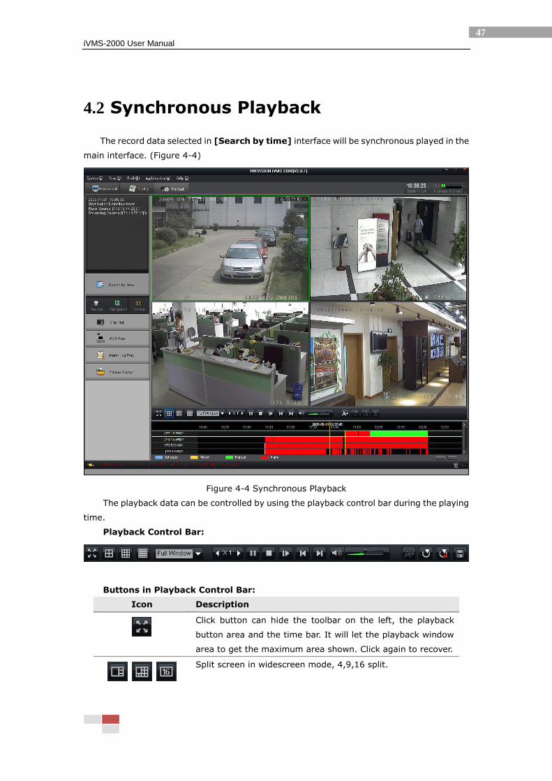
4.2 Synchronous Playback
The record data selected in [Search by time] interface will be synchronous played in the
main interface. (Figure 4-4)
Figure 4-4 Synchronous Playback
The playback data can be controlled by using the playback control bar during the playing
time.
Playback Control Bar:
Buttons in Playback Control Bar:
Icon Description
Click button can hide the toolbar on the left, the playback
button area and the time bar. It will let the playback window
area to get the maximum area shown. Click again to recover.
Split screen in widescreen mode, 4,9,16 split.
iVMS-2000 User Manual
48
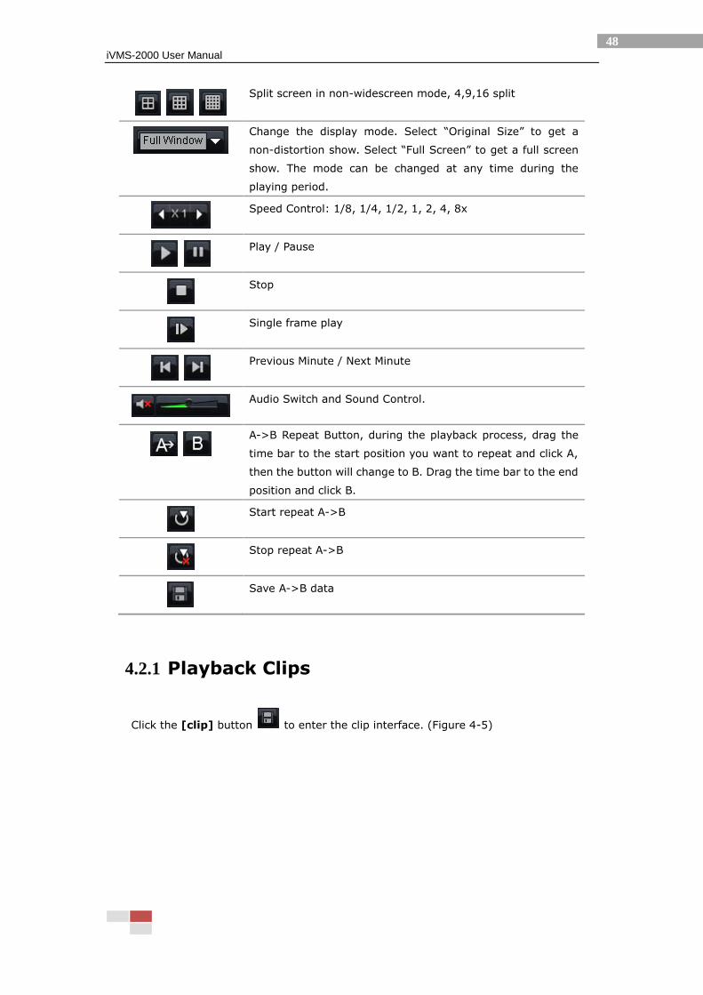
Split screen in non-widescreen mode, 4,9,16 split
Change the display mode. Select “Original Size” to get a
non-distortion show. Select “Full Screen” to get a full screen
show. The mode can be changed at any time during the
playing period.
Speed Control: 1/8, 1/4, 1/2, 1, 2, 4, 8x
Play / Pause
Stop
Single frame play
Previous Minute / Next Minute
Audio Switch and Sound Control.
A->B Repeat Button, during the playback process, drag the
time bar to the start position you want to repeat and click A,
then the button will change to B. Drag the time bar to the end
position and click B.
Start repeat A->B
Stop repeat A->B
Save A->B data
4.2.1 Playback Clips
Click the [clip] button to enter the clip interface. (Figure 4-5)
iVMS-2000 User Manual
49
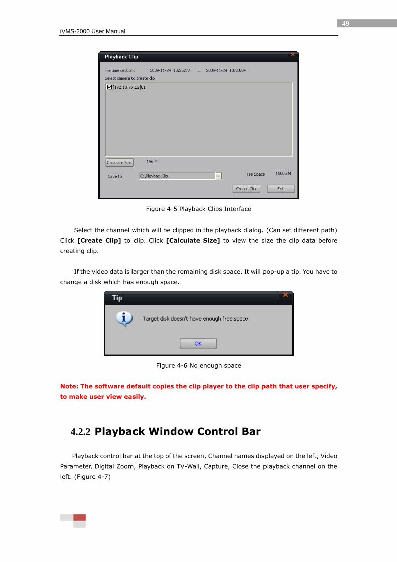
Figure 4-5 Playback Clips Interface
Select the channel which will be clipped in the playback dialog. (Can set different path)
Click [Create Clip] to clip. Click [Calculate Size] to view the size the clip data before
creating clip.
If the video data is larger than the remaining disk space. It will pop-up a tip. You have to
change a disk which has enough space.
Figure 4-6 No enough space
Note: The software default copies the clip player to the clip path that user specify,
to make user view easily.
4.2.2 Playback Window Control Bar
Playback control bar at the top of the screen, Channel names displayed on the left, Video
Parameter, Digital Zoom, Playback on TV-Wall, Capture, Close the playback channel on the
left. (Figure 4-7)

iVMS-2000 User Manual
50
Figure 4-7 Playback Windows
Buttons in the playback window bar:
Icon Name Description
Video Parameter Change the video parameter, including Brightness,
Contrast, Saturation, Hue, and can copy the
configuration to all channels or recover to default
value. (Figure 4-13)
Digital Zoom The same as the digital zoom function of the
preview window in the console platform.
Playback on TV-Wall Output the image of the playback window in the
TV-Wall
Capture Capture in current playback window. It will pop-up
a dialog which have the path (set in the system
parameter) and status (Success or Fail)
information. Click the dialog can view the capture
image.
Close Channel Close the playback window.
iVMS-2000 User Manual
51
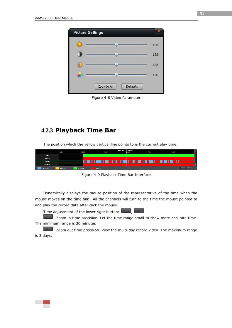
Figure 4-8 Video Parameter
4.2.3 Playback Time Bar
The position which the yellow vertical line points to is the current play time.
Figure 4-9 Playback Time Bar Interface
Dynamically displays the mouse position of the representative of the time when the
mouse moves on the time bar. All the channels will turn to the time the mouse pointed to
and play the record data after click the mouse.
Time adjustment of the lower right button: ,
: Zoom in time precision. Let the time range small to show more accurate time.
The minimum range is 30 minutes
: Zoom out time precision. View the multi-day record video. The maximum range
is 3 days.
iVMS-2000 User Manual
52
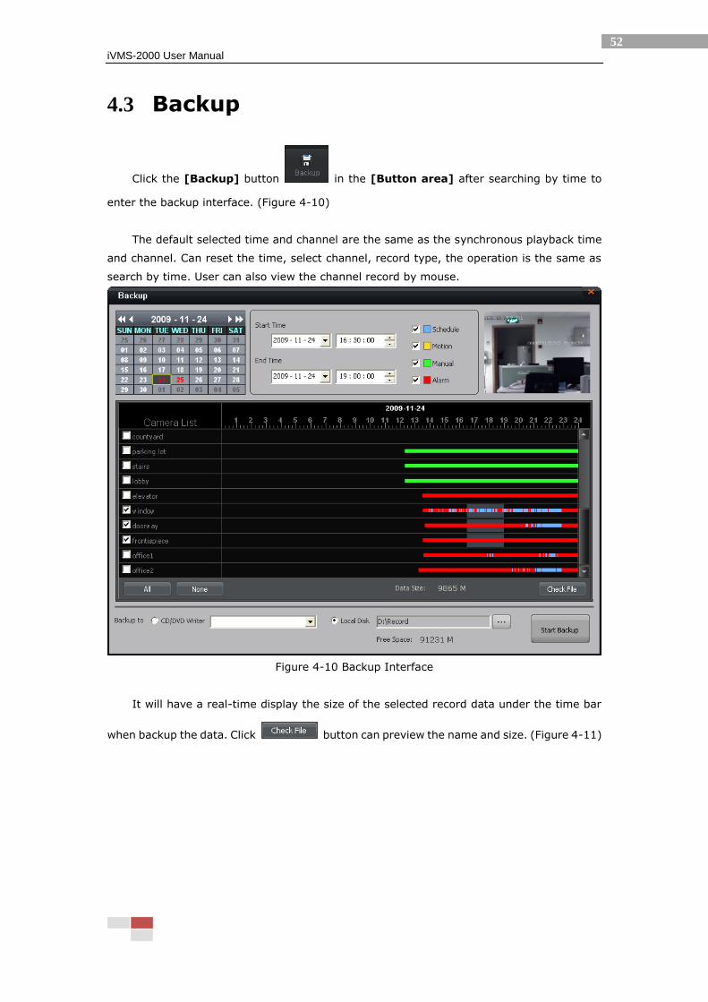
4.3 Backup
Click the [Backup] button in the [Button area] after searching by time to
enter the backup interface. (Figure 4-10)
The default selected time and channel are the same as the synchronous playback time
and channel. Can reset the time, select channel, record type, the operation is the same as
search by time. User can also view the channel record by mouse.
Figure 4-10 Backup Interface
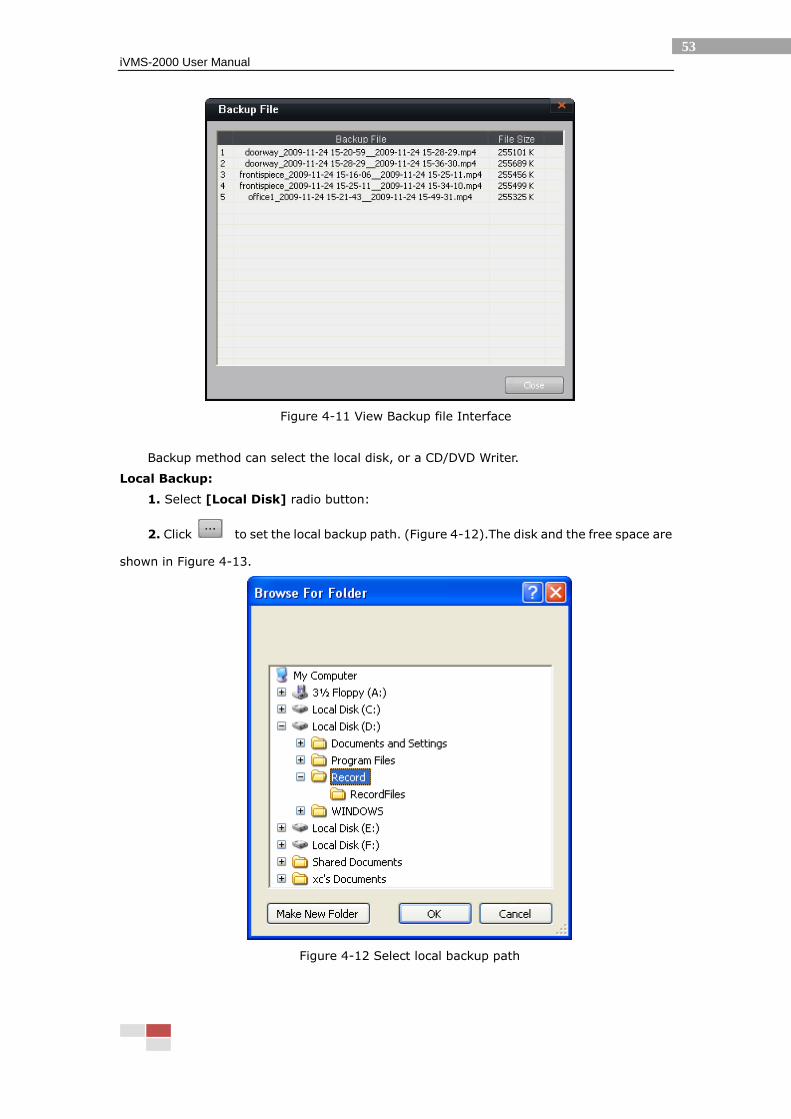
It will have a real-time display the size of the selected record data under the time bar
when backup the data. Click button can preview the name and size. (Figure 4-11)
iVMS-2000 User Manual
53
Figure 4-11 View Backup file Interface
Backup method can select the local disk, or a CD/DVD Writer.
Local Backup:
1. Select [Local Disk] radio button:
2. Click to set the local backup path. (Figure 4-12).The disk and the free space are
shown in Figure 4-13.
Figure 4-12 Select local backup path
iVMS-2000 User Manual
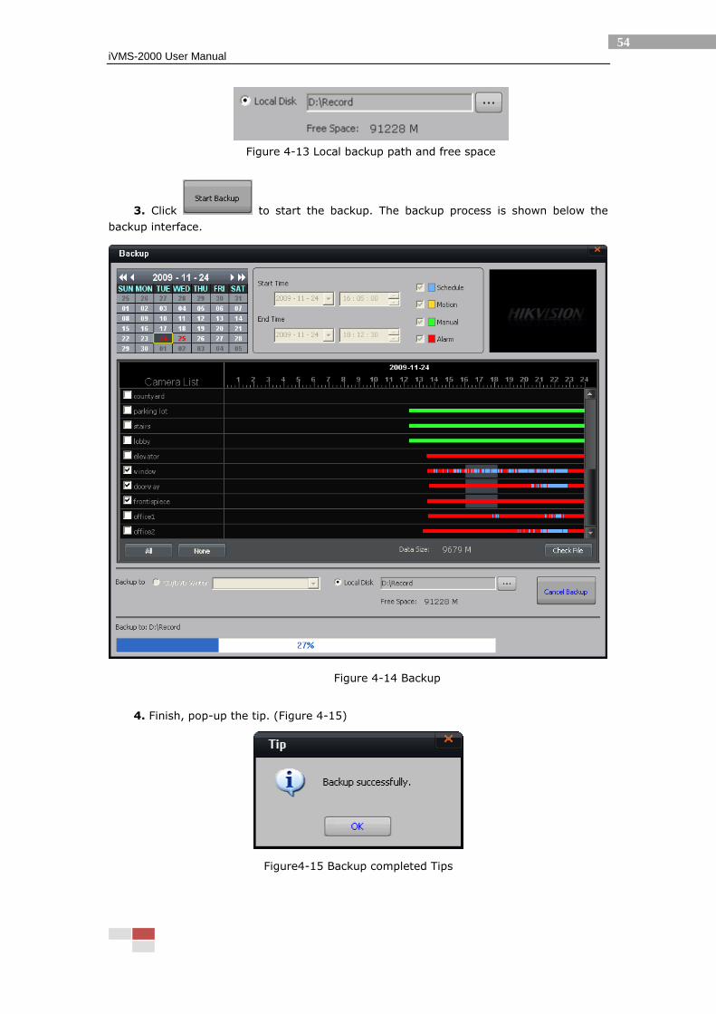
54
Figure 4-13 Local backup path and free space
3. Click to start the backup. The backup process is shown below the
backup interface.
Figure 4-14 Backup
4. Finish, pop-up the tip. (Figure 4-15)
Figure4-15 Backup completed Tips
iVMS-2000 User Manual
55
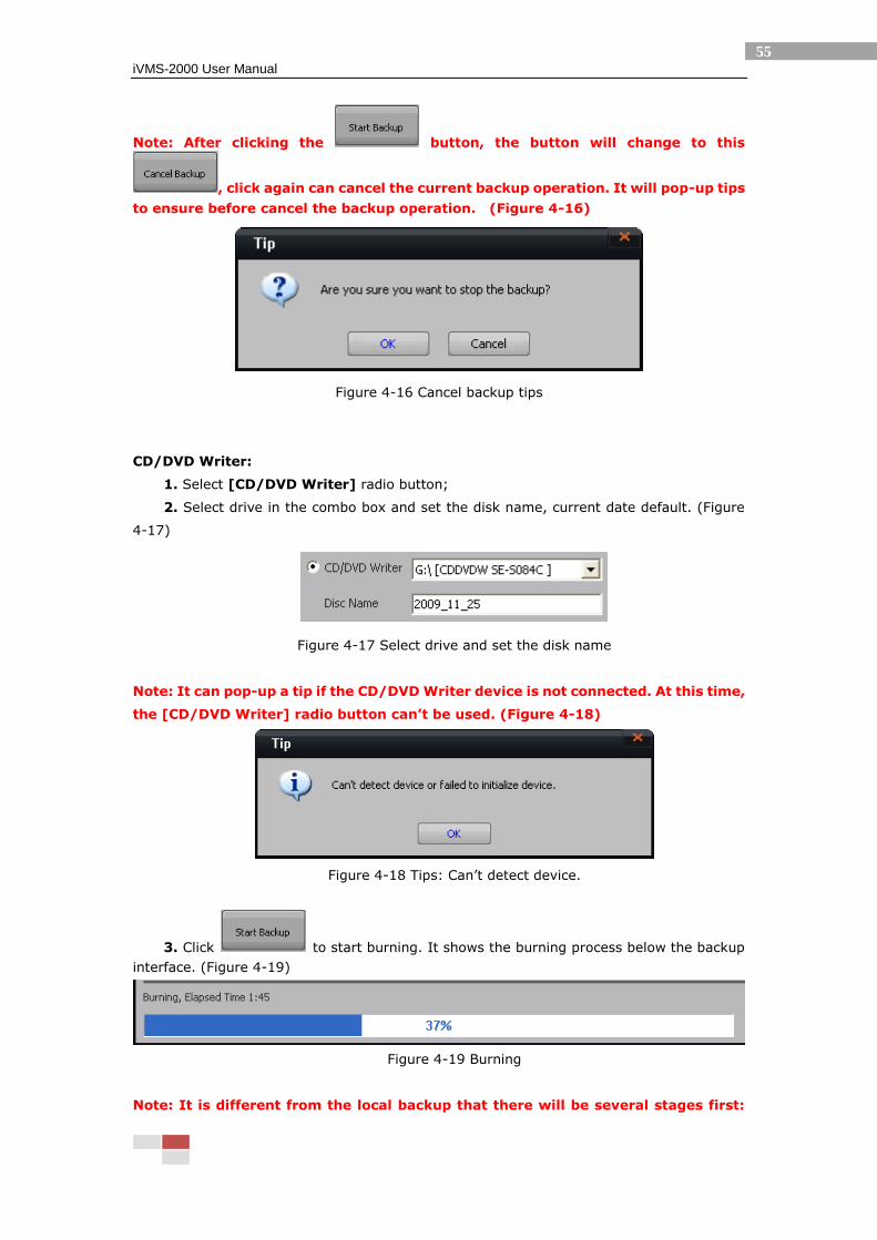
Note: After clicking the button, the button will change to this
, click again can cancel the current backup operation. It will pop-up tips
to ensure before cancel the backup operation. (Figure 4-16)
Figure 4-16 Cancel backup tips
CD/DVD Writer:
1. Select [CD/DVD Writer] radio button;
2. Select drive in the combo box and set the disk name, current date default. (Figure
4-17)
Figure 4-17 Select drive and set the disk name
Note: It can pop-up a tip if the CD/DVD Writer device is not connected. At this time,
the [CD/DVD Writer] radio button can’t be used. (Figure 4-18)
Figure 4-18 Tips: Can’t detect device.
3. Click to start burning. It shows the burning process below the backup
interface. (Figure 4-19)
Figure 4-19 Burning
Note: It is different from the local backup that there will be several stages first:
iVMS-2000 User Manual
56
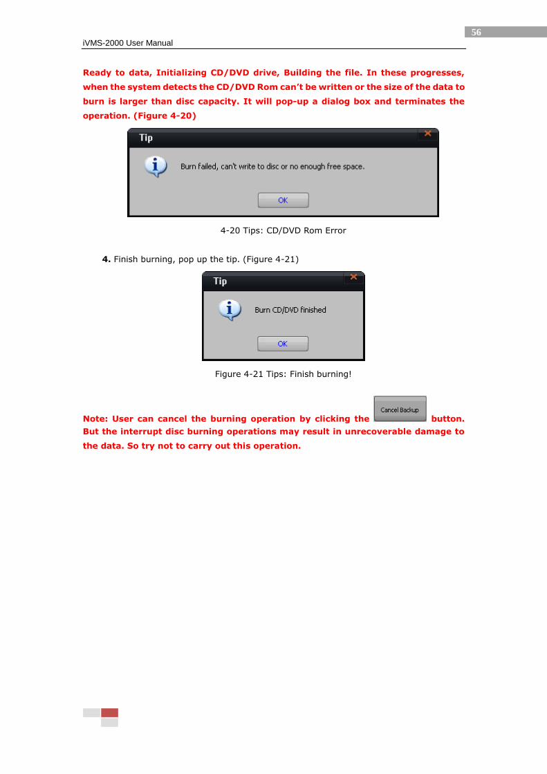
Ready to data, Initializing CD/DVD drive, Building the file. In these progresses,
when the system detects the CD/DVD Rom can’t be written or the size of the data to
burn is larger than disc capacity. It will pop-up a dialog box and terminates the
operation. (Figure 4-20)
4-20 Tips: CD/DVD Rom Error
4. Finish burning, pop up the tip. (Figure 4-21)
Figure 4-21 Tips: Finish burning!
Note: User can cancel the burning operation by clicking the button.
But the interrupt disc burning operations may result in unrecoverable damage to
the data. So try not to carry out this operation.
iVMS-2000 User Manual
57
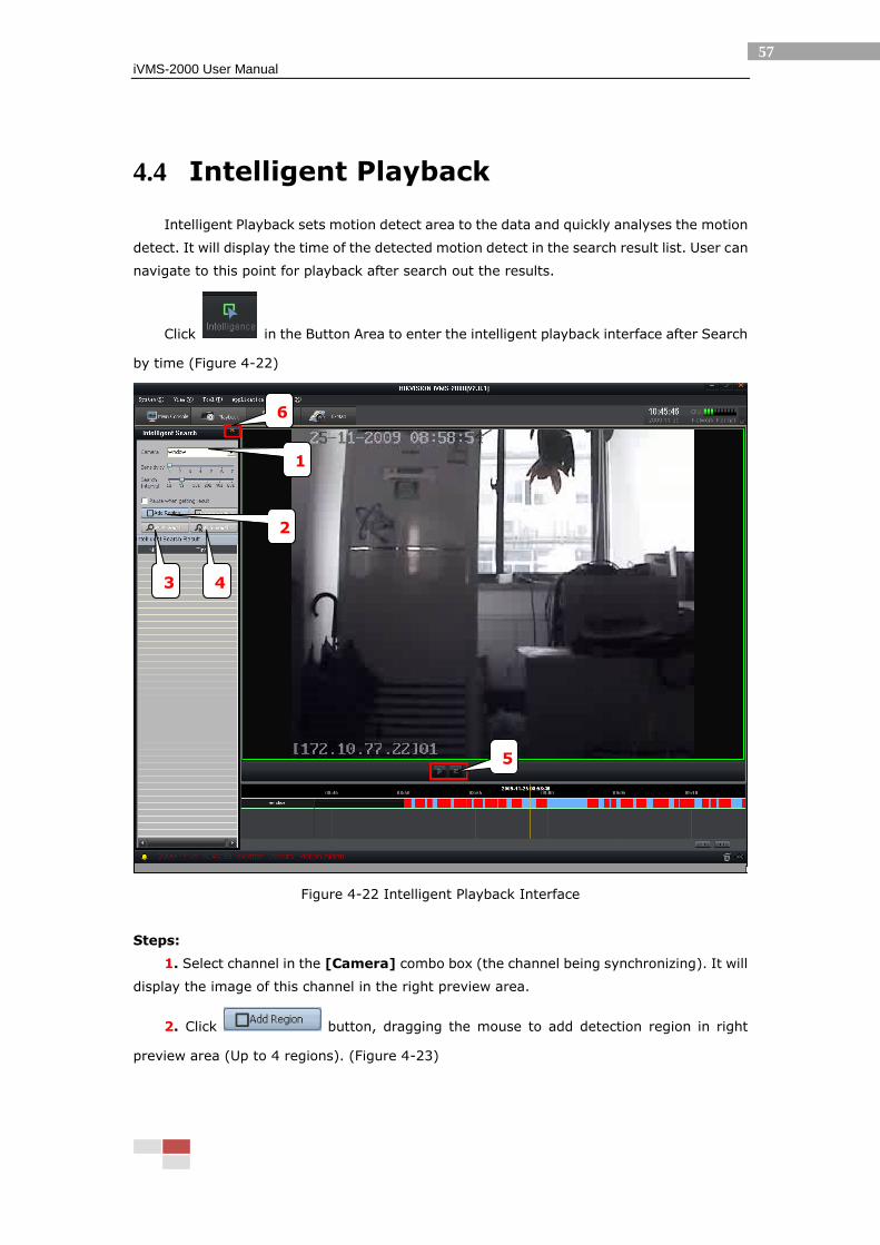
4.4 Intelligent Playback
Intelligent Playback sets motion detect area to the data and quickly analyses the motion
detect. It will display the time of the detected motion detect in the search result list. User can
navigate to this point for playback after search out the results.
Click in the Button Area to enter the intelligent playback interface after Search
by time (Figure 4-22)
Figure 4-22 Intelligent Playback Interface
Steps:
1. Select channel in the [Camera] combo box (the channel being synchronizing). It will
display the image of this channel in the right preview area.
2. Click button, dragging the mouse to add detection region in right
preview area (Up to 4 regions). (Figure 4-23)
6
3
1
5
4
2
iVMS-2000 User Manual
58
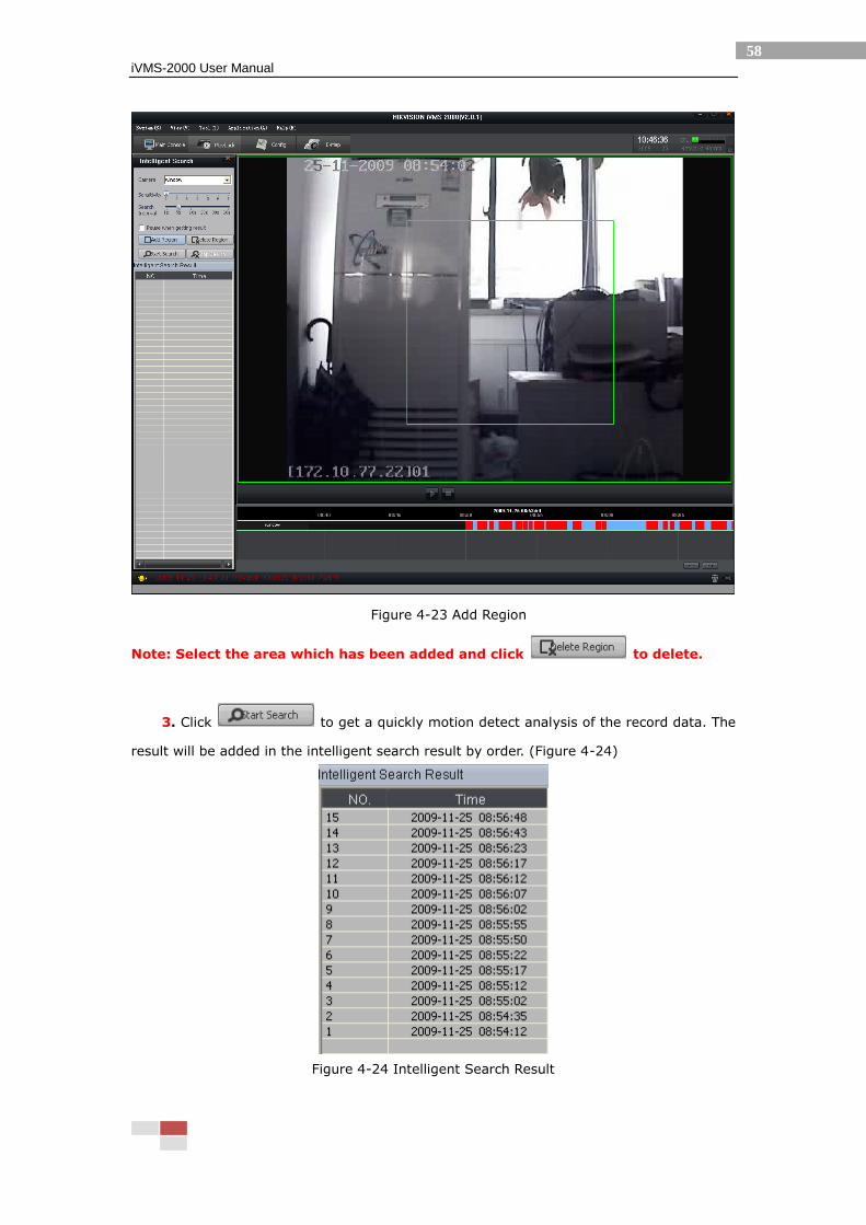
Figure 4-23 Add Region
Note: Select the area which has been added and click to delete.
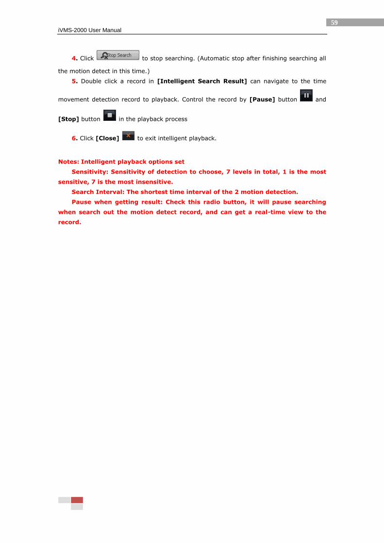
3. Click to get a quickly motion detect analysis of the record data. The
result will be added in the intelligent search result by order. (Figure 4-24)
Figure 4-24 Intelligent Search Result
iVMS-2000 User Manual
59
4. Click to stop searching. (Automatic stop after finishing searching all
the motion detect in this time.)
5. Double click a record in [Intelligent Search Result] can navigate to the time
movement detection record to playback. Control the record by [Pause] button and
[Stop] button in the playback process
6. Click [Close] to exit intelligent playback.
Notes: Intelligent playback options set
Sensitivity: Sensitivity of detection to choose, 7 levels in total, 1 is the most
sensitive, 7 is the most insensitive.
Search Interval: The shortest time interval of the 2 motion detection.
Pause when getting result: Check this radio button, it will pause searching
when search out the motion detect record, and can get a real-time view to the
record.

iVMS-2000 User Manual
60
4.5 Section Playback
Section Playback: In accordance with set starting and ending time, average the
single-channel record to 4/9/16 sections by the record time. Then playback one channel
record data by the segment at the same time.
Click [Section] in the [Button Area] to enter the section playback interface.
(Figure 4-25)
Figure 4-25 Section Playback Interface
Steps:
1. Select channel in the [Camera] combo box (the channel being synchronizing);
2. Set the start time and the end time, and select the number of sections (4/9/16).
3. Click [Play] button to start section playback. The section information is displayed in
the left [Section Info]. Split screen automatically adjust according to the number of
sections.
4. The function of the control bar button is the same as the synchronous playback, can
control the section playback.
5
1
2
3
4

iVMS-2000 User Manual
61
5. Click [Close] to exit Section Playback.
Note: Section playback is non-synchronous play mode. When operate the time bar
by clicking the mouse left button, the control works only to the section that the
mouse operates. When select a playback window, it can display the selected status
of the section and display the current play time in the time bar.
iVMS-2000 User Manual
62
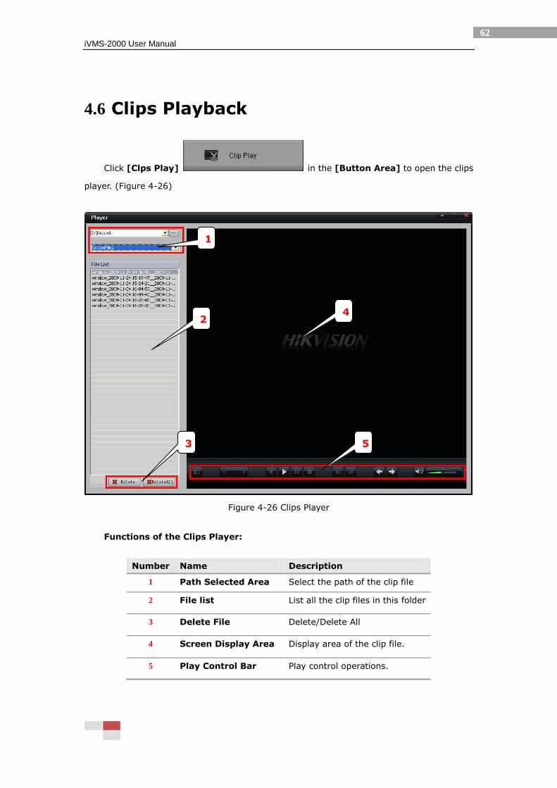
4.6 Clips Playback
Click [Clps Play] in the [Button Area] to open the clips
player. (Figure 4-26)
Figure 4-26 Clips Player
Functions of the Clips Player:
Number Name Description
1 Path Selected Area Select the path of the clip file
2 File list List all the clip files in this folder
3 Delete File Delete/Delete All
4 Screen Display Area Display area of the clip file.
5 Play Control Bar Play control operations.
2
5
4
1
3

iVMS-2000 User Manual
63
Button functions in the Play Control Bar:
Icon Description
Capture. Create a folder named Picture in the program
directory by default, and save the capture file in this folder.
Playback button.
Play button
Pause button
Stop button
Previous frame / Next frame button. Can play the record file by
frame.
Speed Control: 1/8, 1/4, 1/2, 1, 2, 4, 8x
Previous file/ Next file in the file list
Sound control
Short cut key:
Key Control
Double Click Full Window/Exit Full Window
Esc Exit the full window play mode
Space Play/Pause(apply to playback mode)
Up/Down Play previous/ next file
Left/Right Play previous/next frame
iVMS-2000 User Manual
64
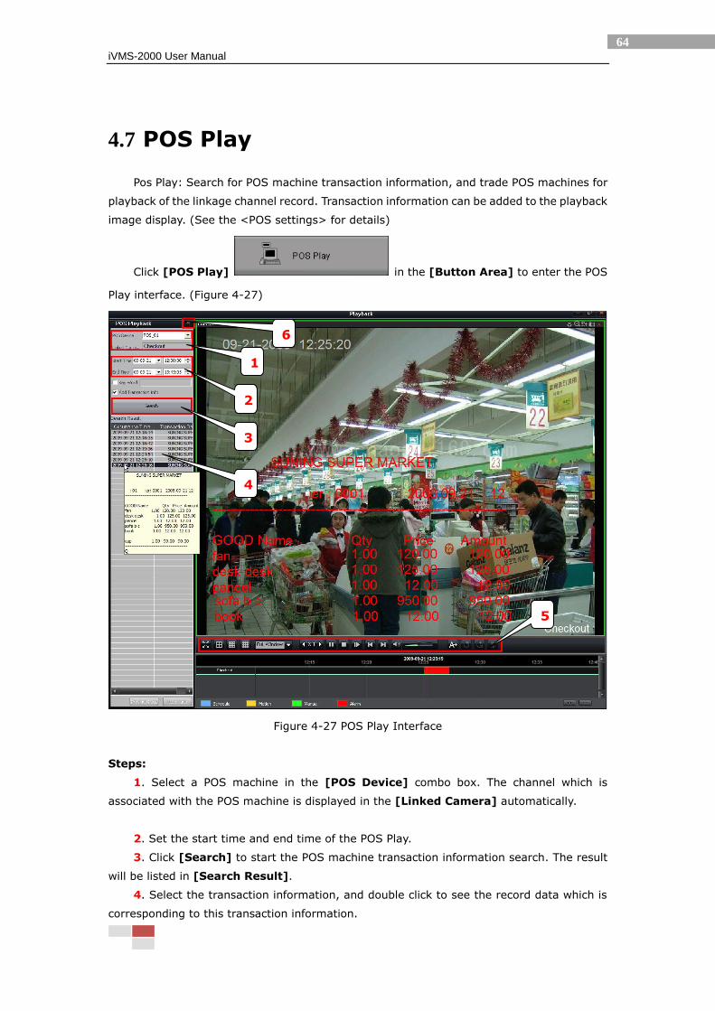
4.7 POS Play
Pos Play: Search for POS machine transaction information, and trade POS machines for
playback of the linkage channel record. Transaction information can be added to the playback
image display. (See the <POS settings> for details)
Click [POS Play] in the [Button Area] to enter the POS
Play interface. (Figure 4-27)
Figure 4-27 POS Play Interface
Steps:
1. Select a POS machine in the [POS Device] combo box. The channel which is
associated with the POS machine is displayed in the [Linked Camera] automatically.
2. Set the start time and end time of the POS Play.
3. Click [Search] to start the POS machine transaction information search. The result
will be listed in [Search Result].
4. Select the transaction information, and double click to see the record data which is
corresponding to this transaction information.
1
2
3
\
6
4
\
5
\
iVMS-2000 User Manual
65
5. The function of the control bar button is the same as the synchronous playback, can
control the POS Play.
6. Click [Close] to exit POS Play.
Notes:
Double click a play, and it will display the POS transaction information for 6 hours
after the start of the data. If you do not want to look this, click a play in the result
list to play other POS transaction data.
Can set the search keywords when set the POS search criteria, check the
[Keywords] option at the top of [search] button, and input the keyword in the edit
box. Then it will only search the transactions which contain the keyword
information.
Can choose whether add the POS machine transaction information to the record
video or not, through the check/uncheck radio button [Add Transaction Info] to
achieve.
Can pop-up a tip that displays the detail transaction information in the mouse
position when the mouse moves to one transaction information in [Transaction
Info] list. It is the same as the information which are added to the record video.
iVMS-2000 User Manual
66
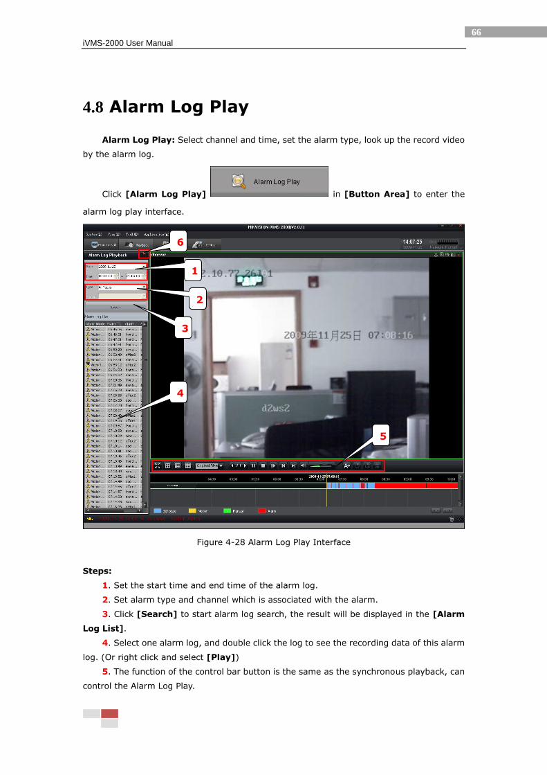
4.8 Alarm Log Play
Alarm Log Play: Select channel and time, set the alarm type, look up the record video
by the alarm log.
Click [Alarm Log Play] in [Button Area] to enter the
alarm log play interface.
Figure 4-28 Alarm Log Play Interface
Steps:
1. Set the start time and end time of the alarm log.
2. Set alarm type and channel which is associated with the alarm.
3. Click [Search] to start alarm log search, the result will be displayed in the [Alarm
Log List].
4. Select one alarm log, and double click the log to see the recording data of this alarm
log. (Or right click and select [Play])
5. The function of the control bar button is the same as the synchronous playback, can
control the Alarm Log Play.
6
1
2
3
\
4
5

iVMS-2000 User Manual
67
6. Click [Close] to exit Alarm Log Play.
Note: It can display the related information of the alarm log by pop-up tips in
[Alarm Log List] when the mouse move to an alarm log.
iVMS-2000 User Manual
68
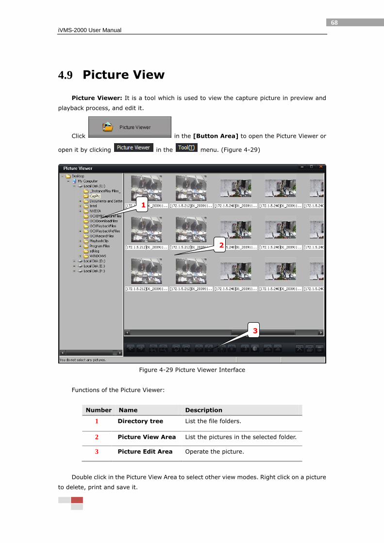
4.9 Picture View
Picture Viewer: It is a tool which is used to view the capture picture in preview and
playback process, and edit it.
Click in the [Button Area] to open the Picture Viewer or
open it by clicking in the menu. (Figure 4-29)
Figure 4-29 Picture Viewer Interface
Functions of the Picture Viewer:
Number Name Description
1 Directory tree List the file folders.
2 Picture View Area List the pictures in the selected folder.
3 Picture Edit Area Operate the picture.
Double click in the Picture View Area to select other view modes. Right click on a picture
to delete, print and save it.
1
2
3
iVMS-2000 User Manual
69
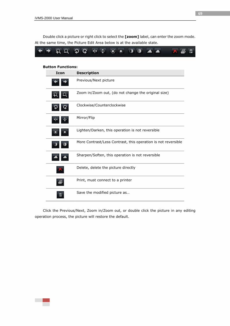
Double click a picture or right click to select the [zoom] label, can enter the zoom mode.
At the same time, the Picture Edit Area below is at the available state.
Button Functions:
Icon Description
Previous/Next picture
Zoom in/Zoom out, (do not change the original size)
Clockwise/Counterclockwise
Mirror/Flip
Lighten/Darken, this operation is not reversible
More Contrast/Less Contrast, this operation is not reversible
Sharpen/Soften, this operation is not reversible
Delete, delete the picture directly
Print, must connect to a printer
Save the modified picture as…
Click the Previous/Next, Zoom in/Zoom out, or double click the picture in any editing
operation process, the picture will restore the default.
iVMS-2000 User Manual
70
5 E-Map
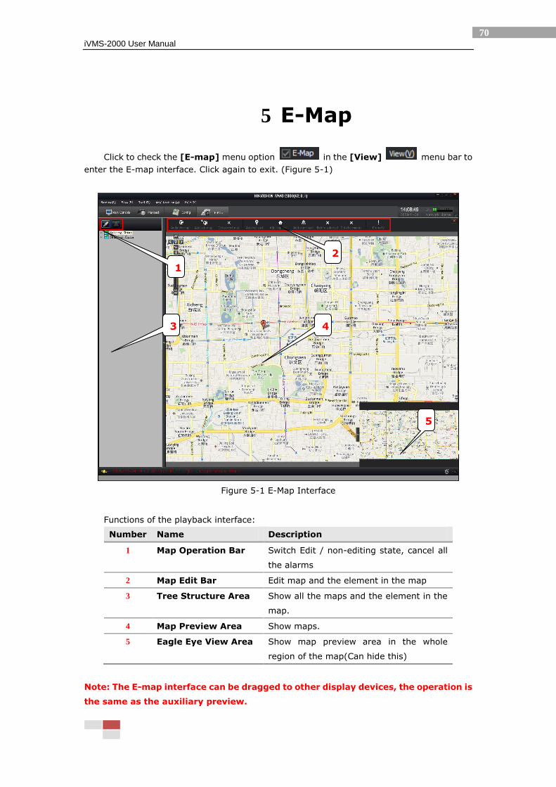
Click to check the [E-map] menu option in the [View] menu bar to
enter the E-map interface. Click again to exit. (Figure 5-1)
Figure 5-1 E-Map Interface
Functions of the playback interface:
Number Name Description
1 Map Operation Bar Switch Edit / non-editing state, cancel all
the alarms
2 Map Edit Bar Edit map and the element in the map
3 Tree Structure Area Show all the maps and the element in the
map.
4 Map Preview Area Show maps.
5 Eagle Eye View Area Show map preview area in the whole
region of the map(Can hide this)
Note: The E-map interface can be dragged to other display devices, the operation is
the same as the auxiliary preview.
2
4 3
5
1
iVMS-2000 User Manual
71
5.1 E-Map Operations
Click [Edit] button to start edit (Figure 5-2) or exit edit (Figure 5-3).
Figure 5-2Edit State
Figure 5-3 Non-editing State
5.1.1 Map Operation
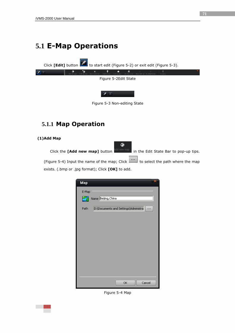
(1)Add Map
Click the [Add new map] button in the Edit State Bar to pop-up tips.
(Figure 5-4) Input the name of the map; Click to select the path where the map
exists. (.bmp or .jpg format); Click [OK] to add.
Figure 5-4 Map
iVMS-2000 User Manual
72
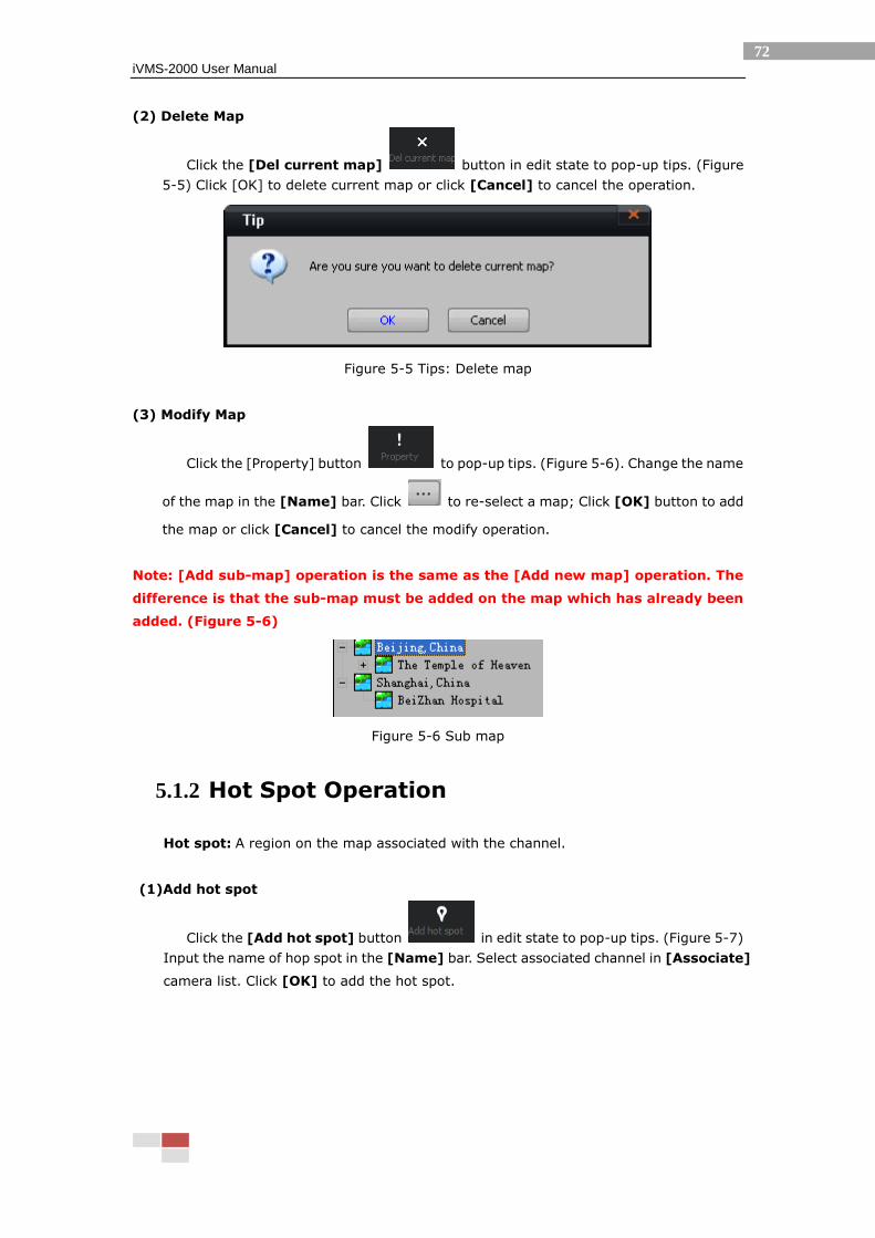
(2) Delete Map
Click the [Del current map] button in edit state to pop-up tips. (Figure
5-5) Click [OK] to delete current map or click [Cancel] to cancel the operation.
Figure 5-5 Tips: Delete map
(3) Modify Map
Click the [Property] button to pop-up tips. (Figure 5-6). Change the name
of the map in the [Name] bar. Click to re-select a map; Click [OK] button to add
the map or click [Cancel] to cancel the modify operation.
Note: [Add sub-map] operation is the same as the [Add new map] operation. The
difference is that the sub-map must be added on the map which has already been
added. (Figure 5-6)
Figure 5-6 Sub map
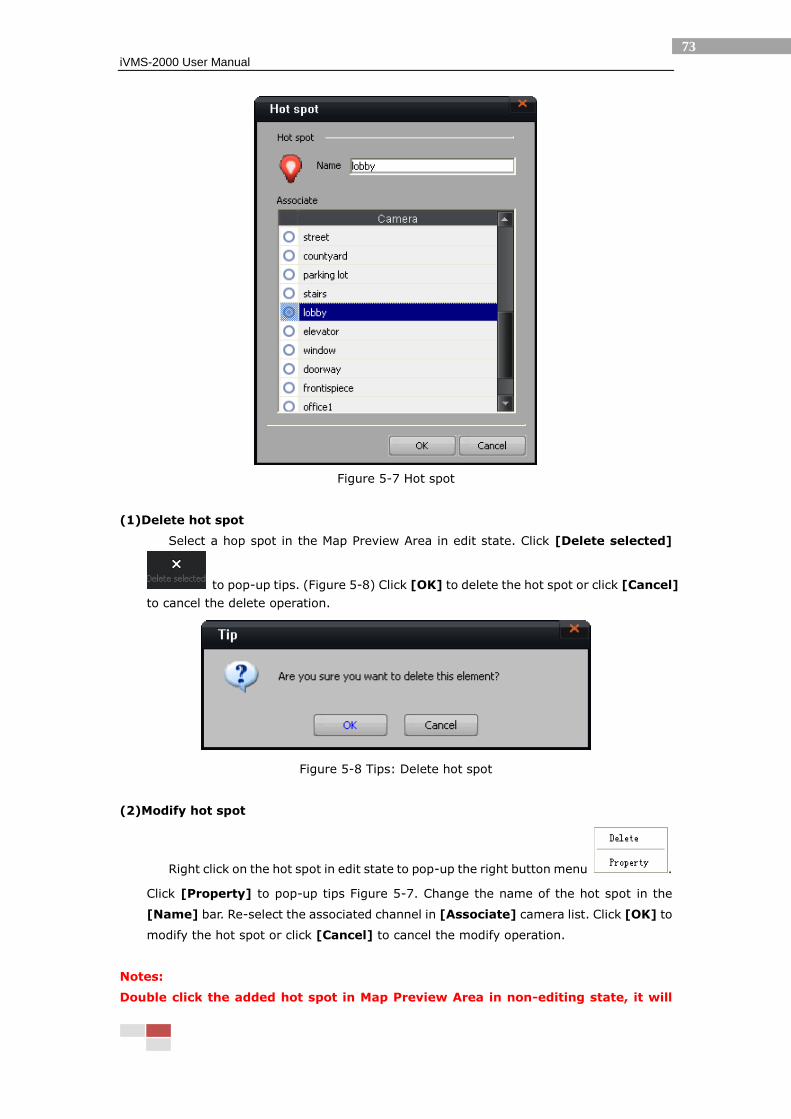
5.1.2 Hot Spot Operation
Hot spot: A region on the map associated with the channel.
(1)Add hot spot
Click the [Add hot spot] button in edit state to pop-up tips. (Figure 5-7)
Input the name of hop spot in the [Name] bar. Select associated channel in [Associate]
camera list. Click [OK] to add the hot spot.
iVMS-2000 User Manual
73
Figure 5-7 Hot spot
(1)Delete hot spot
Select a hop spot in the Map Preview Area in edit state. Click [Delete selected]
to pop-up tips. (Figure 5-8) Click [OK] to delete the hot spot or click [Cancel]
to cancel the delete operation.
Figure 5-8 Tips: Delete hot spot
(2)Modify hot spot
Right click on the hot spot in edit state to pop-up the right button menu .
Click [Property] to pop-up tips Figure 5-7. Change the name of the hot spot in the
[Name] bar. Re-select the associated channel in [Associate] camera list. Click [OK] to
modify the hot spot or click [Cancel] to cancel the modify operation.
Notes:
Double click the added hot spot in Map Preview Area in non-editing state, it will
iVMS-2000 User Manual
74
pop-up tips that displays the associated channel to this hot spot.
The hot spot icon will be lighted when there is an alarm in the associated hot spot
after the linkage alarm configuration is finished. (See 6.6.1 Add Alarm Linkage for
detail)
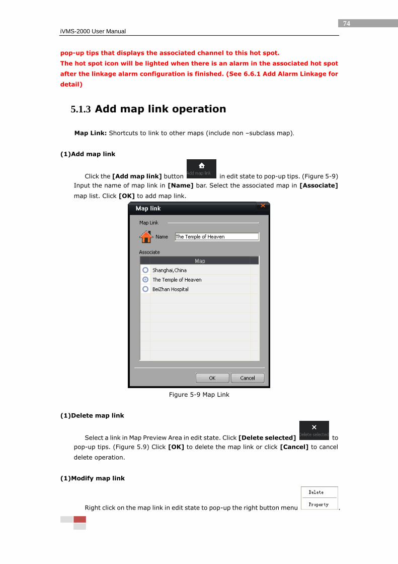
5.1.3 Add map link operation
Map Link: Shortcuts to link to other maps (include non –subclass map).
(1)Add map link
Click the [Add map link] button in edit state to pop-up tips. (Figure 5-9)
Input the name of map link in [Name] bar. Select the associated map in [Associate]
map list. Click [OK] to add map link.
Figure 5-9 Map Link
(1)Delete map link
Select a link in Map Preview Area in edit state. Click [Delete selected] to
pop-up tips. (Figure 5.9) Click [OK] to delete the map link or click [Cancel] to cancel
delete operation.
(1)Modify map link
Right click on the map link in edit state to pop-up the right button menu .
iVMS-2000 User Manual
75
Click [Property] to pop-up tips Figure 5-9. Change the name of the map link in the
[Name] bar. Re-select the associated map in [Associate] camera list. Click [OK] to
modify the map link or click [Cancel] to cancel the modify operation.
Note: Double click the added map link in Map Preview Area in non-editing state can
directly turn to the associated map of the map link.
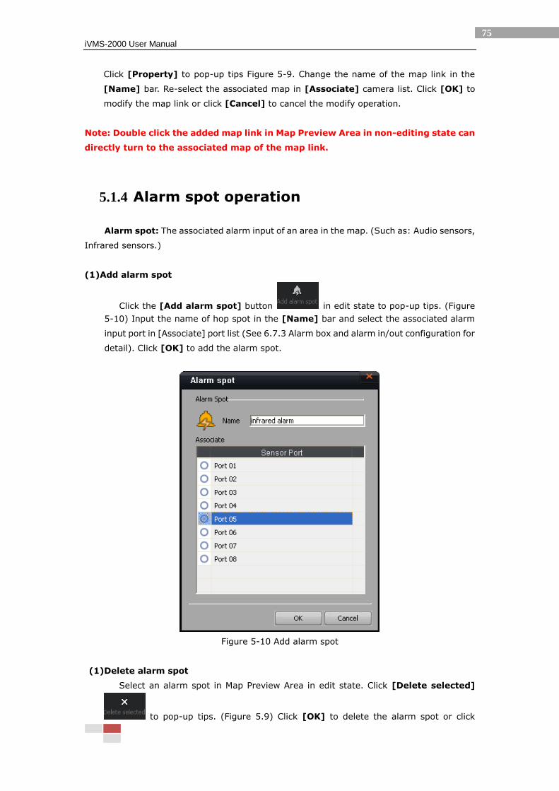
5.1.4 Alarm spot operation
Alarm spot: The associated alarm input of an area in the map. (Such as: Audio sensors,
Infrared sensors.)
(1)Add alarm spot
Click the [Add alarm spot] button in edit state to pop-up tips. (Figure
5-10) Input the name of hop spot in the [Name] bar and select the associated alarm
input port in [Associate] port list (See 6.7.3 Alarm box and alarm in/out configuration for
detail). Click [OK] to add the alarm spot.
Figure 5-10 Add alarm spot
(1)Delete alarm spot
Select an alarm spot in Map Preview Area in edit state. Click [Delete selected]
to pop-up tips. (Figure 5.9) Click [OK] to delete the alarm spot or click
iVMS-2000 User Manual
76
[Cancel] to cancel delete operation.
(1) Modify alarm spot
Right click on the alarm spot in edit state to pop-up the right button menu .
Click [Property] to pop-up tips Figure 5-10. Change the name of the alarm spot in the
[Name] bar. Re-select the associated alarm input port in [Associate] port list. Click
[OK] to modify the alarm spot or click [Cancel] to cancel the modify operation.
Note: The alarm spot icon will be lighted when there is an alarm input in the
associated alarm input spot after the linkage alarm configuration is finished. (See
6.7.3 Alarm box and alarm in/out configuration for detail)
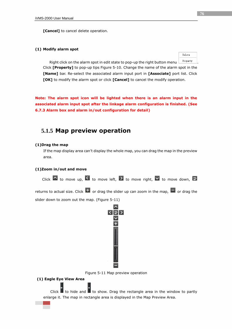
5.1.5 Map preview operation
(1)Drag the map
If the map display area can’t display the whole map, you can drag the map in the preview
area.
(1)Zoom in/out and move
Click to move up, to move left, to move right, to move down,
returns to actual size. Click or drag the slider up can zoom in the map, or drag the
slider down to zoom out the map. (Figure 5-11)
Figure 5-11 Map preview operation
(1) Eagle Eye View Area
Click to hide and to show. Drag the rectangle area in the window to partly
enlarge it. The map in rectangle area is displayed in the Map Preview Area.
iVMS-2000 User Manual
77
Figure 5-12 Eagle Eye View
iVMS-2000 User Manual
78
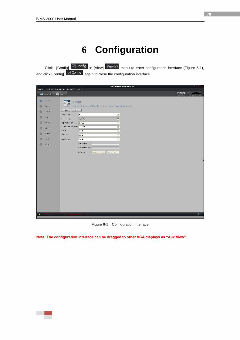
6 Configuration
Click [Config] in [View] menu to enter configuration interface (Figure 6-1),
and click [Config] again to close the configuration interface.
Figure 6-1 Configuration Interface
Note: The configuration interface can be dragged to other VGA displays as “Aux View”.
iVMS-2000 User Manual
79
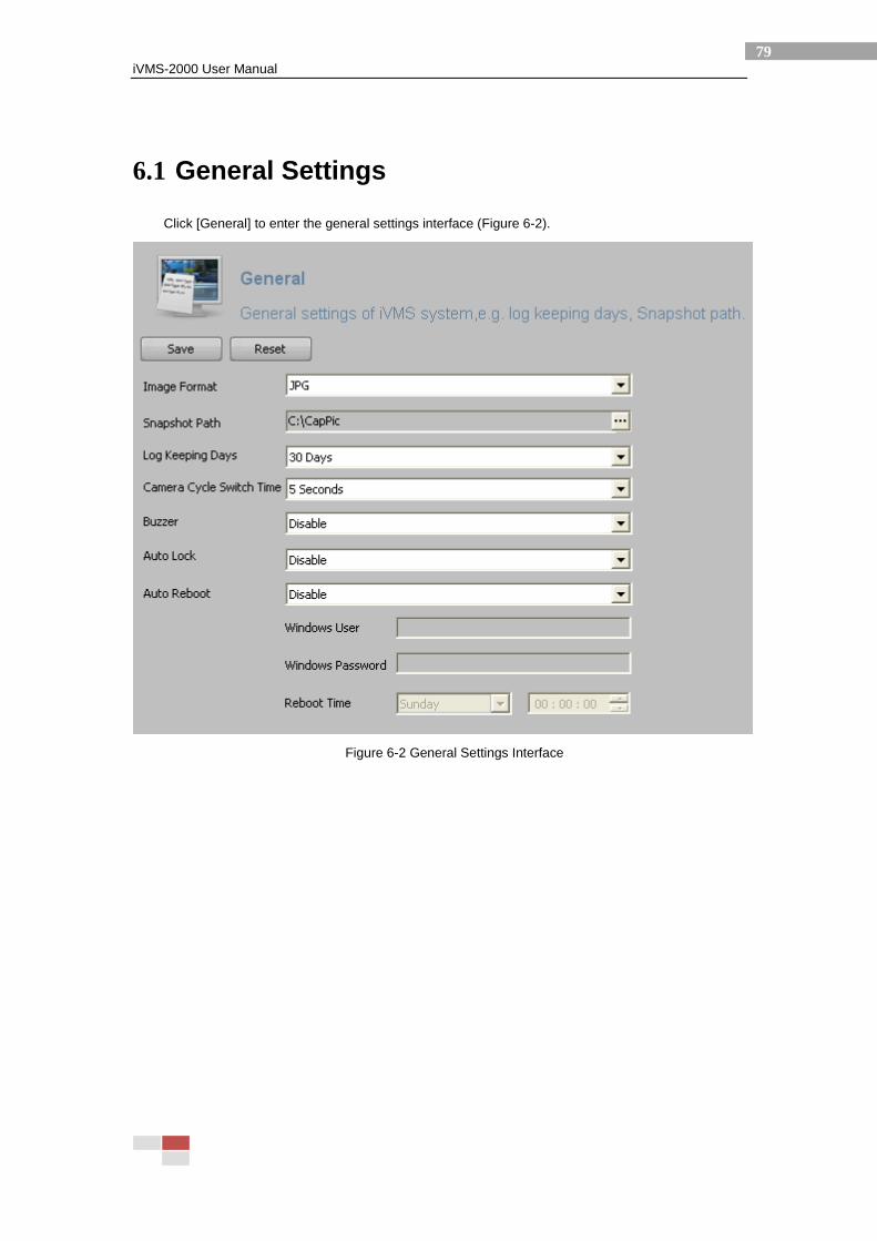
6.1 General Settings
Click [General] to enter the general settings interface (Figure 6-2).
Figure 6-2 General Settings Interface
iVMS-2000 User Manual
80
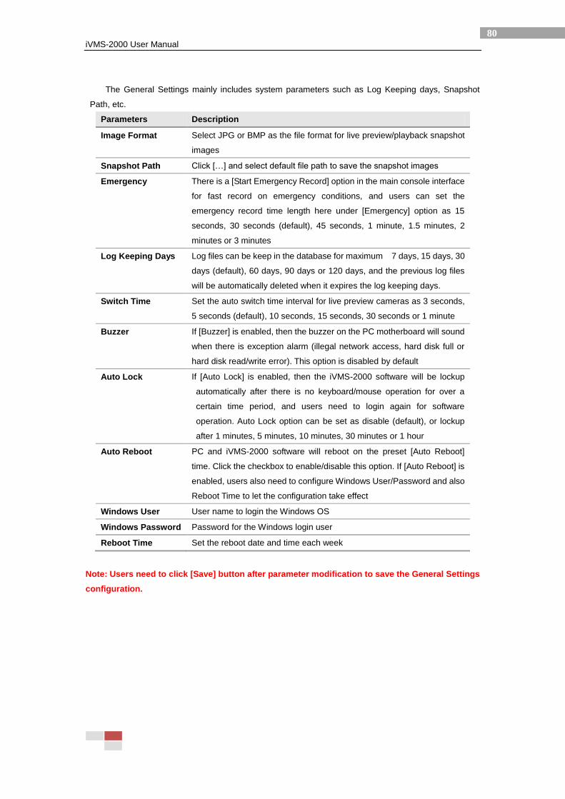
The General Settings mainly includes system parameters such as Log Keeping days, Snapshot
Path, etc.
Parameters Description
Image Format Select JPG or BMP as the file format for live preview/playback snapshot
images
Snapshot Path Click […] and select default file path to save the snapshot images
Emergency There is a [Start Emergency Record] option in the main console interface
for fast record on emergency conditions, and users can set the
emergency record time length here under [Emergency] option as 15
seconds, 30 seconds (default), 45 seconds, 1 minute, 1.5 minutes, 2
minutes or 3 minutes
Log Keeping Days Log files can be keep in the database for maximum 7 days, 15 days, 30
days (default), 60 days, 90 days or 120 days, and the previous log files
will be automatically deleted when it expires the log keeping days.
Switch Time Set the auto switch time interval for live preview cameras as 3 seconds,
5 seconds (default), 10 seconds, 15 seconds, 30 seconds or 1 minute
Buzzer If [Buzzer] is enabled, then the buzzer on the PC motherboard will sound
when there is exception alarm (illegal network access, hard disk full or
hard disk read/write error). This option is disabled by default
Auto Lock If [Auto Lock] is enabled, then the iVMS-2000 software will be lockup
automatically after there is no keyboard/mouse operation for over a
certain time period, and users need to login again for software
operation. Auto Lock option can be set as disable (default), or lockup
after 1 minutes, 5 minutes, 10 minutes, 30 minutes or 1 hour
Auto Reboot PC and iVMS-2000 software will reboot on the preset [Auto Reboot]
time. Click the checkbox to enable/disable this option. If [Auto Reboot] is
enabled, users also need to configure Windows User/Password and also
Reboot Time to let the configuration take effect
Windows User User name to login the Windows OS
Windows Password Password for the Windows login user
Reboot Time Set the reboot date and time each week
Note: Users need to click [Save] button after parameter modification to save the General Settings
configuration.
iVMS-2000 User Manual
81
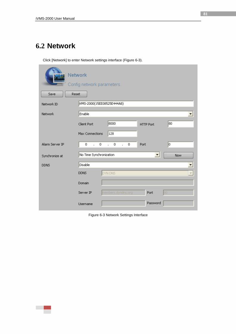
6.2 Network
Click [Network] to enter Network settings interface (Figure 6-3).
Figure 6-3 Network Settings Interface
iVMS-2000 User Manual
82
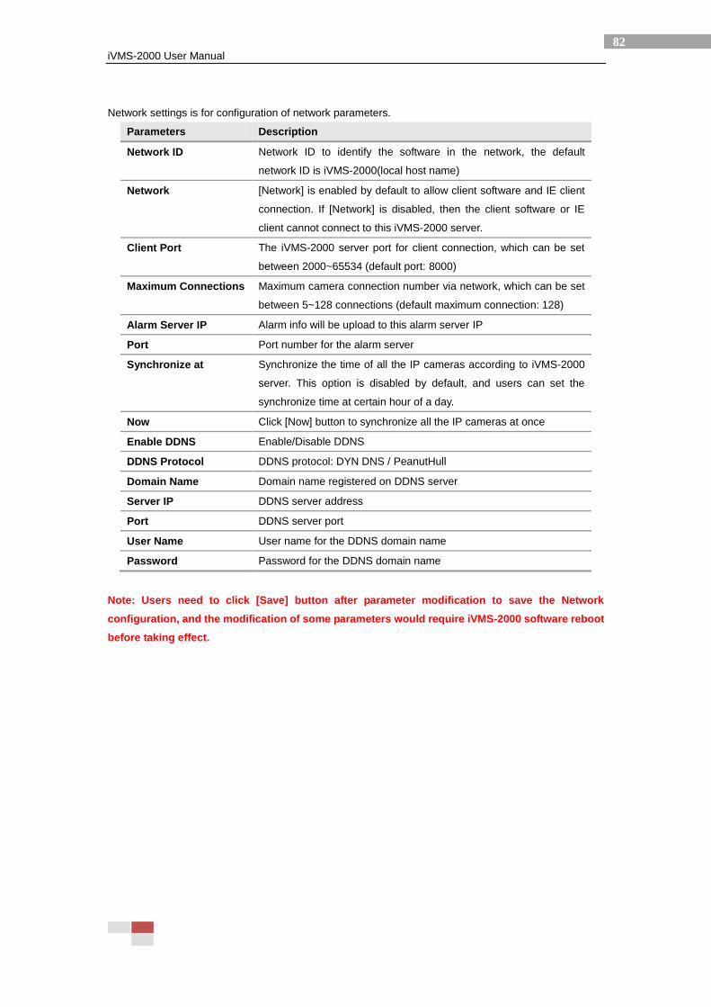
Network settings is for configuration of network parameters.
Parameters Description
Network ID Network ID to identify the software in the network, the default
network ID is iVMS-2000(local host name)
Network [Network] is enabled by default to allow client software and IE client
connection. If [Network] is disabled, then the client software or IE
client cannot connect to this iVMS-2000 server.
Client Port The iVMS-2000 server port for client connection, which can be set
between 2000~65534 (default port: 8000)
Maximum Connections Maximum camera connection number via network, which can be set
between 5~128 connections (default maximum connection: 128)
Alarm Server IP Alarm info will be upload to this alarm server IP
Port Port number for the alarm server
Synchronize at Synchronize the time of all the IP cameras according to iVMS-2000
server. This option is disabled by default, and users can set the
synchronize time at certain hour of a day.
Now Click [Now] button to synchronize all the IP cameras at once
Enable DDNS Enable/Disable DDNS
DDNS Protocol DDNS protocol: DYN DNS / PeanutHull
Domain Name Domain name registered on DDNS server
Server IP DDNS server address
Port DDNS server port
User Name User name for the DDNS domain name
Password Password for the DDNS domain name
Note: Users need to click [Save] button after parameter modification to save the Network
configuration, and the modification of some parameters would require iVMS-2000 software reboot
before taking effect.
iVMS-2000 User Manual
83
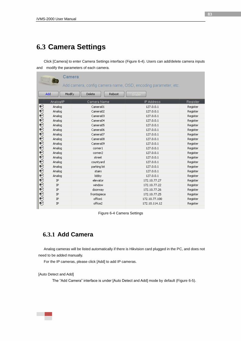
6.3 Camera Settings
Click [Camera] to enter Camera Settings interface (Figure 6-4). Users can add/delete camera inputs
and modify the parameters of each camera.
Figure 6-4 Camera Settings
6.3.1 Add Camera
Analog cameras will be listed automatically if there is Hikvision card plugged in the PC, and does not
need to be added manually.
For the IP cameras, please click [Add] to add IP cameras.
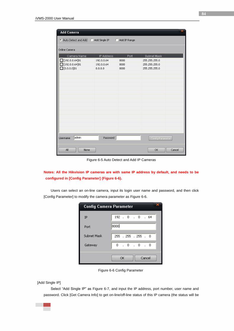
[Auto Detect and Add]
The “Add Camera” interface is under [Auto Detect and Add] mode by default (Figure 6-5).
iVMS-2000 User Manual
84
Figure 6-5 Auto Detect and Add IP Cameras
Notes: All the Hikvision IP cameras are with same IP address by default, and needs to be
configured in [Config Parameter] (Figure 6-6).
Users can select an on-line camera, input its login user name and password, and then click
[Config Parameter] to modify the camera parameter as Figure 6-6.
Figure 6-6 Config Parameter
[Add Single IP]
Select “Add Single IP” as Figure 6-7, and input the IP address, port number, user name and
password. Click [Get Camera Info] to get on-line/off-line status of this IP camera (the status will be
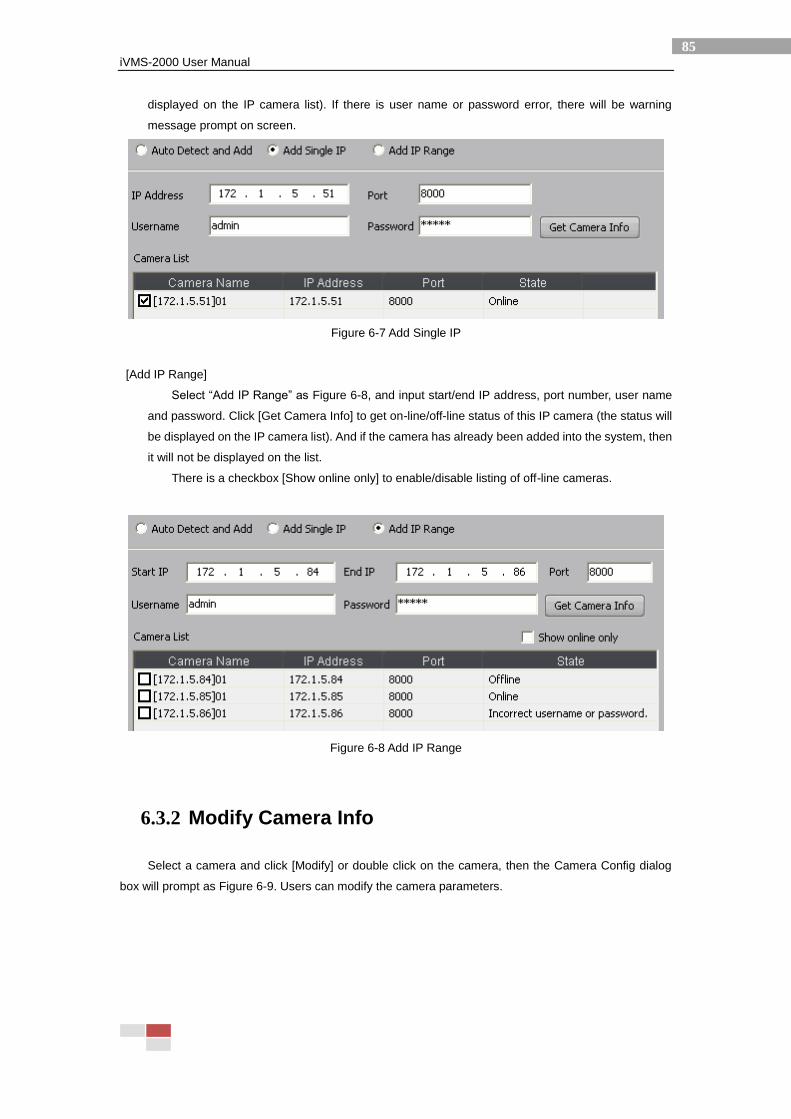
iVMS-2000 User Manual
85
displayed on the IP camera list). If there is user name or password error, there will be warning
message prompt on screen.
Figure 6-7 Add Single IP
[Add IP Range]
Select “Add IP Range” as Figure 6-8, and input start/end IP address, port number, user name
and password. Click [Get Camera Info] to get on-line/off-line status of this IP camera (the status will
be displayed on the IP camera list). And if the camera has already been added into the system, then
it will not be displayed on the list.
There is a checkbox [Show online only] to enable/disable listing of off-line cameras.
Figure 6-8 Add IP Range
6.3.2 Modify Camera Info
Select a camera and click [Modify] or double click on the camera, then the Camera Config dialog
box will prompt as Figure 6-9. Users can modify the camera parameters.
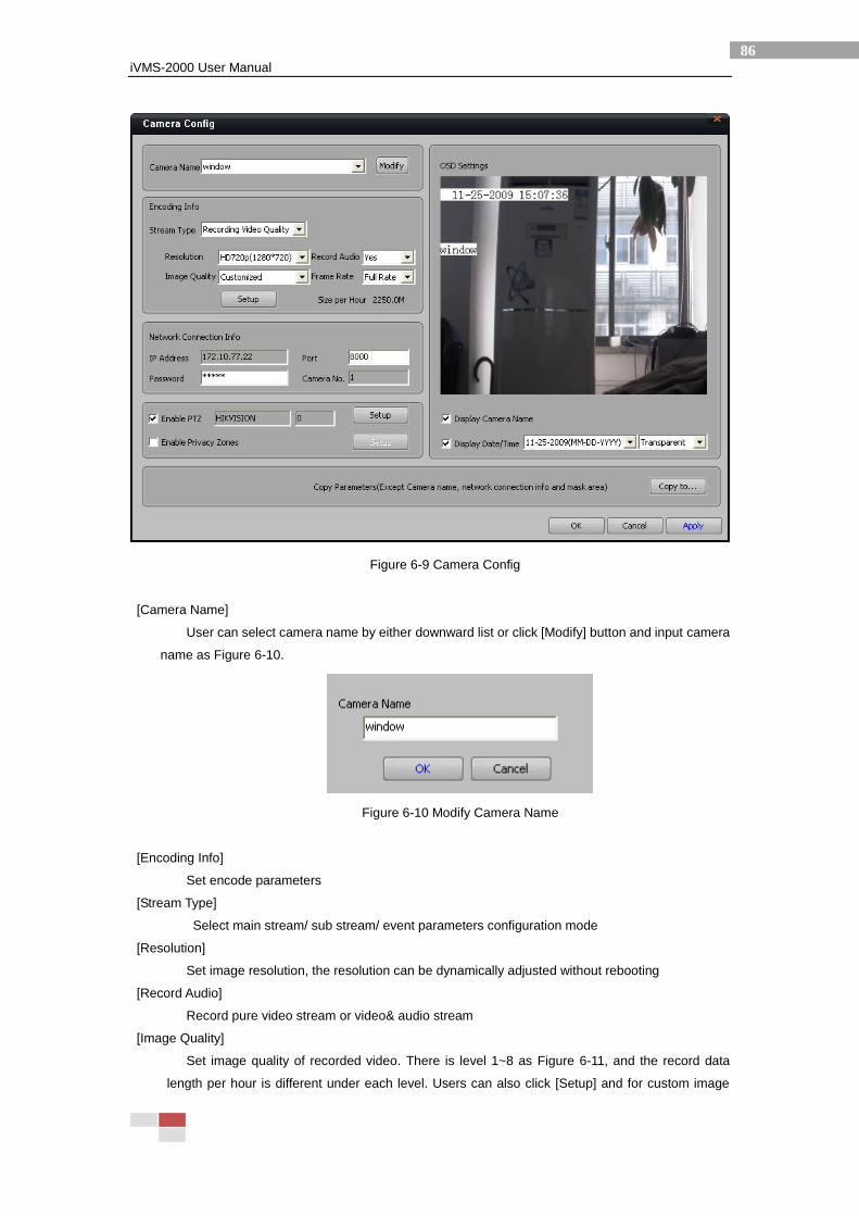
iVMS-2000 User Manual
86
Figure 6-9 Camera Config
[Camera Name]
User can select camera name by either downward list or click [Modify] button and input camera
name as Figure 6-10.
Figure 6-10 Modify Camera Name
[Encoding Info]
Set encode parameters
[Stream Type]
Select main stream/ sub stream/ event parameters configuration mode
[Resolution]
Set image resolution, the resolution can be dynamically adjusted without rebooting
[Record Audio]
Record pure video stream or video& audio stream
[Image Quality]
Set image quality of recorded video. There is level 1~8 as Figure 6-11, and the record data
length per hour is different under each level. Users can also click [Setup] and for custom image
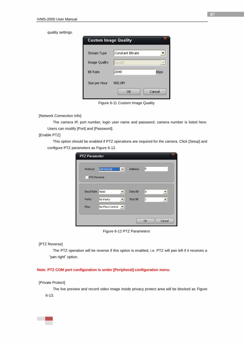
iVMS-2000 User Manual
87
quality settings.
Figure 6-11 Custom Image Quality
[Network Connection Info]
The camera IP, port number, login user name and password, camera number is listed here.
Users can modify [Port] and [Password].
[Enable PTZ]
This option should be enabled if PTZ operations are required for the camera. Click [Setup] and
configure PTZ parameters as Figure 6-12.
Figure 6-12 PTZ Parameters
[PTZ Reverse]
The PTZ operation will be reverse if this option is enabled, i.e. PTZ will pan left if it receives a
“pan right” option.
Note: PTZ COM port configuration is under [Peripheral] configuration menu.
[Private Protect]
The live preview and record video image inside privacy protect area will be blocked as Figure
6-13.
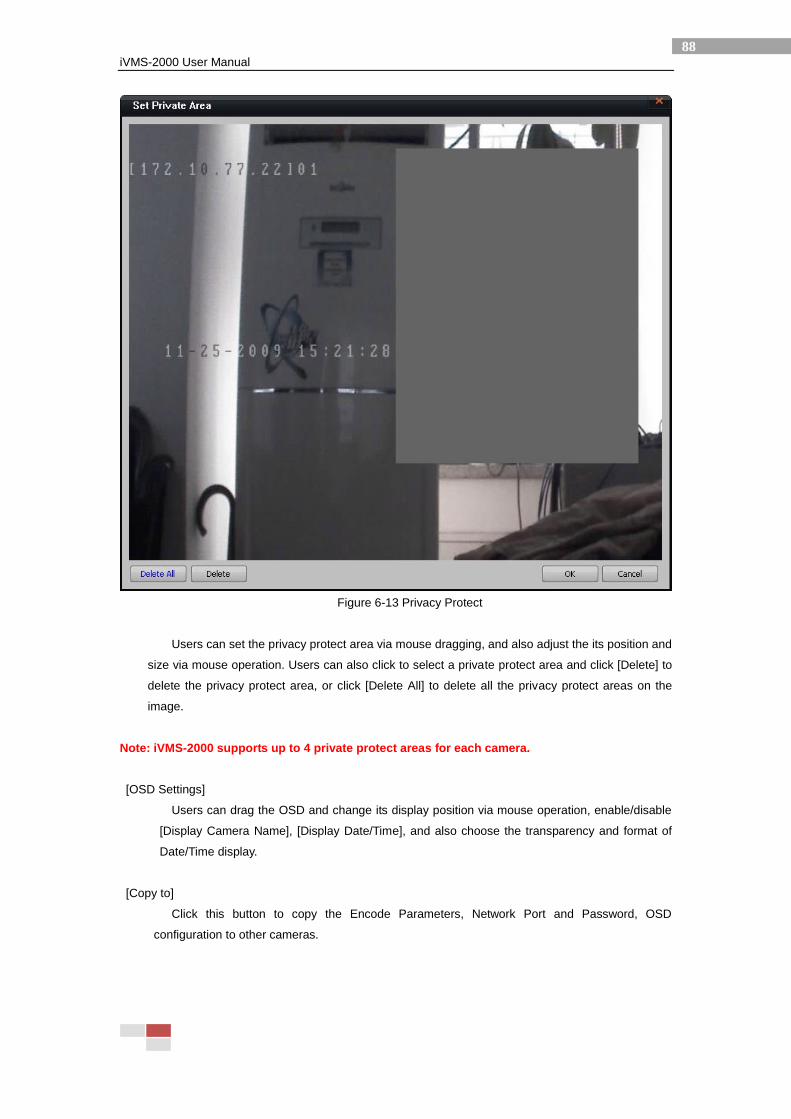
iVMS-2000 User Manual
88
Figure 6-13 Privacy Protect
Users can set the privacy protect area via mouse dragging, and also adjust the its position and
size via mouse operation. Users can also click to select a private protect area and click [Delete] to
delete the privacy protect area, or click [Delete All] to delete all the privacy protect areas on the
image.
Note: iVMS-2000 supports up to 4 private protect areas for each camera.
[OSD Settings]
Users can drag the OSD and change its display position via mouse operation, enable/disable
[Display Camera Name], [Display Date/Time], and also choose the transparency and format of
Date/Time display.
[Copy to]
Click this button to copy the Encode Parameters, Network Port and Password, OSD
configuration to other cameras.
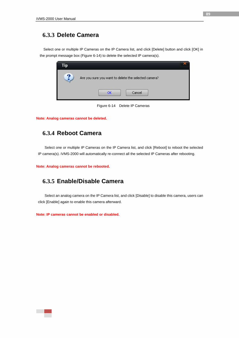
iVMS-2000 User Manual
89
6.3.3 Delete Camera
Select one or multiple IP Cameras on the IP Camera list, and click [Delete] button and click [OK] in
the prompt message box (Figure 6-14) to delete the selected IP camera(s).
Figure 6-14 Delete IP Cameras
Note: Analog cameras cannot be deleted.
6.3.4 Reboot Camera
Select one or multiple IP Cameras on the IP Camera list, and click [Reboot] to reboot the selected
IP camera(s). iVMS-2000 will automatically re-connect all the selected IP Cameras after rebooting.
Note: Analog cameras cannot be rebooted.
6.3.5 Enable/Disable Camera
Select an analog camera on the IP Camera list, and click [Disable] to disable this camera, users can
click [Enable] again to enable this camera afterward.
Note: IP cameras cannot be enabled or disabled.
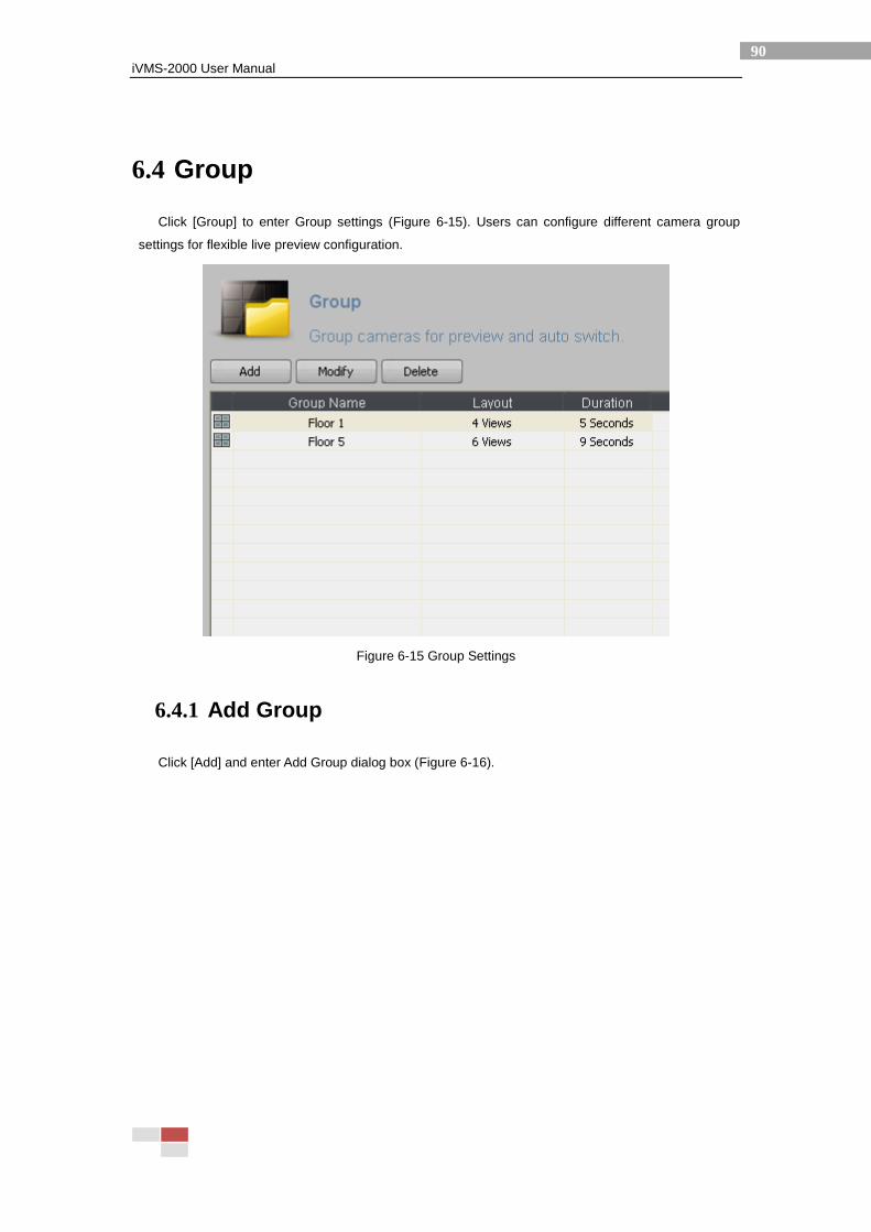
iVMS-2000 User Manual
90
6.4 Group
Click [Group] to enter Group settings (Figure 6-15). Users can configure different camera group
settings for flexible live preview configuration.
Figure 6-15 Group Settings
6.4.1 Add Group
Click [Add] and enter Add Group dialog box (Figure 6-16).
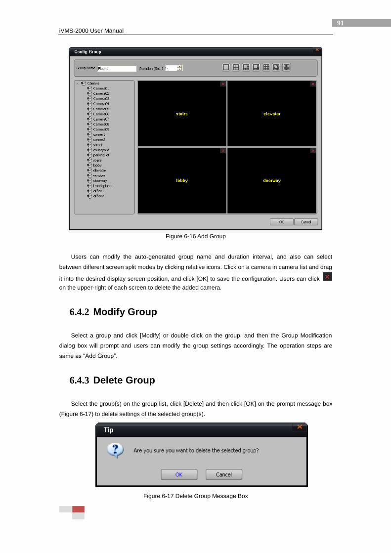
iVMS-2000 User Manual
91
Figure 6-16 Add Group
Users can modify the auto-generated group name and duration interval, and also can select
between different screen split modes by clicking relative icons. Click on a camera in camera list and drag
it into the desired display screen position, and click [OK] to save the configuration. Users can click
on the upper-right of each screen to delete the added camera.
6.4.2 Modify Group
Select a group and click [Modify] or double click on the group, and then the Group Modification
dialog box will prompt and users can modify the group settings accordingly. The operation steps are
same as “Add Group”.
6.4.3 Delete Group
Select the group(s) on the group list, click [Delete] and then click [OK] on the prompt message box
(Figure 6-17) to delete settings of the selected group(s).
Figure 6-17 Delete Group Message Box
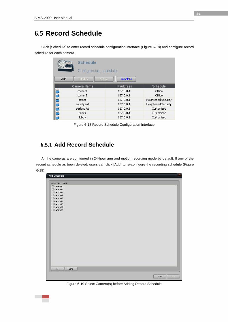
iVMS-2000 User Manual
92
6.5 Record Schedule
Click [Schedule] to enter record schedule configuration interface (Figure 6-18) and configure record
schedule for each camera.
Figure 6-18 Record Schedule Configuration Interface
6.5.1 Add Record Schedule
All the cameras are configured in 24-hour arm and motion recording mode by default. If any of the
record schedule as been deleted, users can click [Add] to re-configure the recording schedule (Figure
6-19).
Figure 6-19 Select Camera(s) before Adding Record Schedule
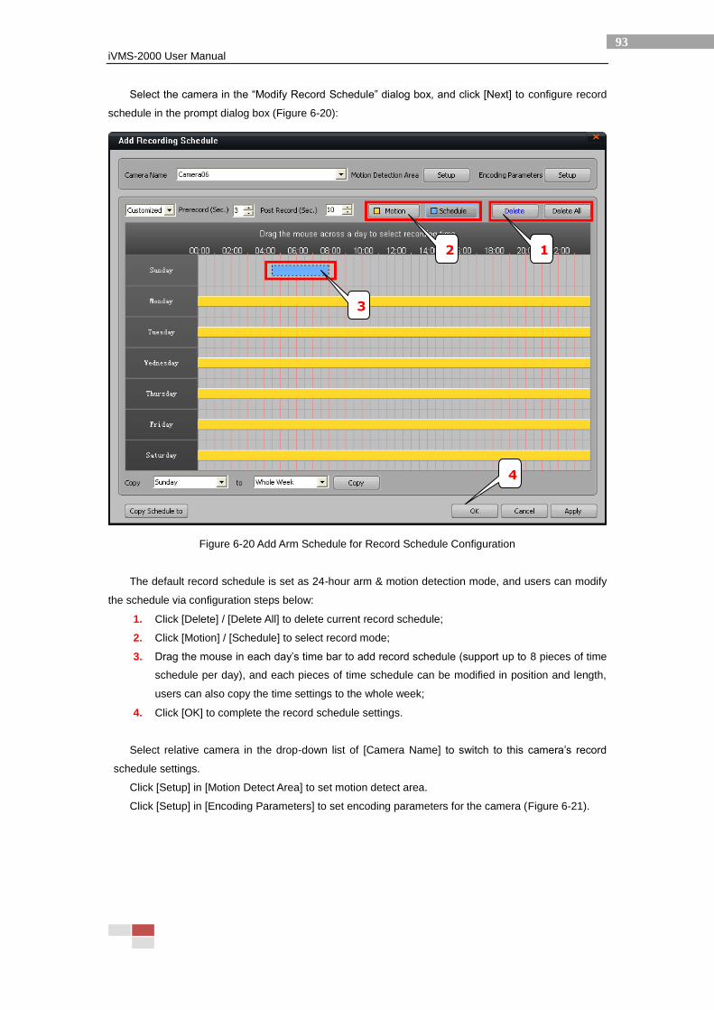
iVMS-2000 User Manual
93
Select the camera in the “Modify Record Schedule” dialog box, and click [Next] to configure record
schedule in the prompt dialog box (Figure 6-20):
Figure 6-20 Add Arm Schedule for Record Schedule Configuration
The default record schedule is set as 24-hour arm & motion detection mode, and users can modify
the schedule via configuration steps below:
1. Click [Delete] / [Delete All] to delete current record schedule;
2. Click [Motion] / [Schedule] to select record mode;
3. Drag the mouse in each day’s time bar to add record schedule (support up to 8 pieces of time
schedule per day), and each pieces of time schedule can be modified in position and length,
users can also copy the time settings to the whole week;
4. Click [OK] to complete the record schedule settings.
Select relative camera in the drop-down list of [Camera Name] to switch to this camera’s record
schedule settings.
Click [Setup] in [Motion Detect Area] to set motion detect area.
Click [Setup] in [Encoding Parameters] to set encoding parameters for the camera (Figure 6-21).
1 2
3
4
iVMS-2000 User Manual
94
Figure 6-21 Encoding Parameters Configuration
Users can select [Customized] or [Template] mode for record schedule setup:
[Customized]
Users can set pre-record time and post-record time under [Customized] mode. Click [Motion]
or [Schedule] to select the record mode for each time period, and then drag the mouse and draw
time schedule on the time bar, and it supports up to 8 record periods per day. Select a certain record
period and click [Delete] to delete this record period, or click [Delete All] directly to delete all the
record period settings for this camera. Click on any of the weekly date to select 24-hour of this day,
and click [Copy Schedule to] to copy the record period settings to other days.
[Template]
Under [Template] mode, users can select record schedule templates which are already edited,
or click [Edit Template] to enter Record Schedule setting dialog box.
[Copy Schedule to]
Copy the record schedule settings to other cameras.
6.5.2 Modify Record Schedule
Select a record schedule and click [Modify] or double click on it to enter Record Schedule setting
dialog box (Figure 6-22) and modify the record schedule.
iVMS-2000 User Manual
95
Figure 6-22 Modify Record Schedule
The modification steps are similar with operation steps in “Add Record Schedule”.
6.5.3 Delete Record Schedule
Select record schedule(s) in the schedule list and click [Delete], click [OK] in the prompt dialog box
(Figure 6-23) to delete the selected record schedule(s).
Figure 6-23 Delete Record Schedule
6.5.4 Record Schedule Template
Click [Template] to enter Record Template dialog box and edit record schedule template (Figure
6-24).
iVMS-2000 User Manual
96
Figure 6-24 Record Schedule Template
There are totally 10 record templates, of which 5 are re-configured (adjustable). Users can select
the template in the drop-down list and edit its content.
Click [Modify] and modify the template name, and edit record period for the template in similar way
as adding record schedule.
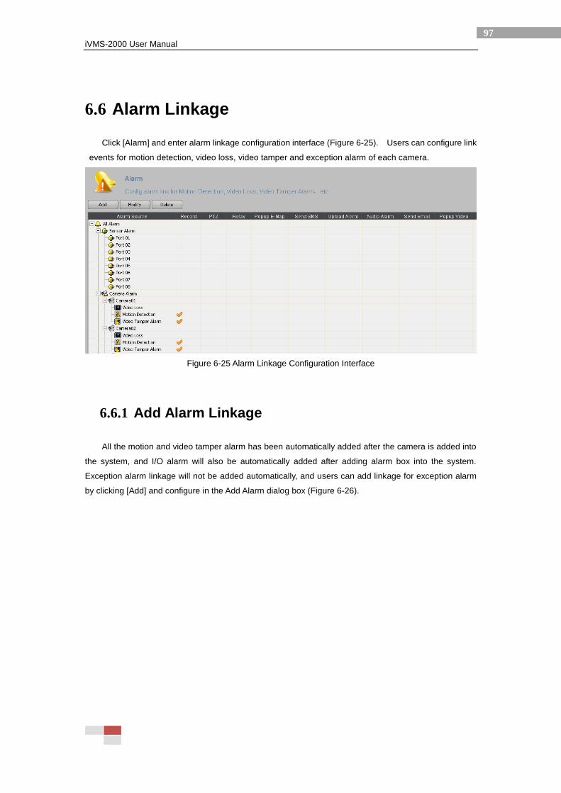
iVMS-2000 User Manual
97
6.6 Alarm Linkage
Click [Alarm] and enter alarm linkage configuration interface (Figure 6-25). Users can configure link
events for motion detection, video loss, video tamper and exception alarm of each camera.
Figure 6-25 Alarm Linkage Configuration Interface
6.6.1 Add Alarm Linkage
All the motion and video tamper alarm has been automatically added after the camera is added into
the system, and I/O alarm will also be automatically added after adding alarm box into the system.
Exception alarm linkage will not be added automatically, and users can add linkage for exception alarm
by clicking [Add] and configure in the Add Alarm dialog box (Figure 6-26).
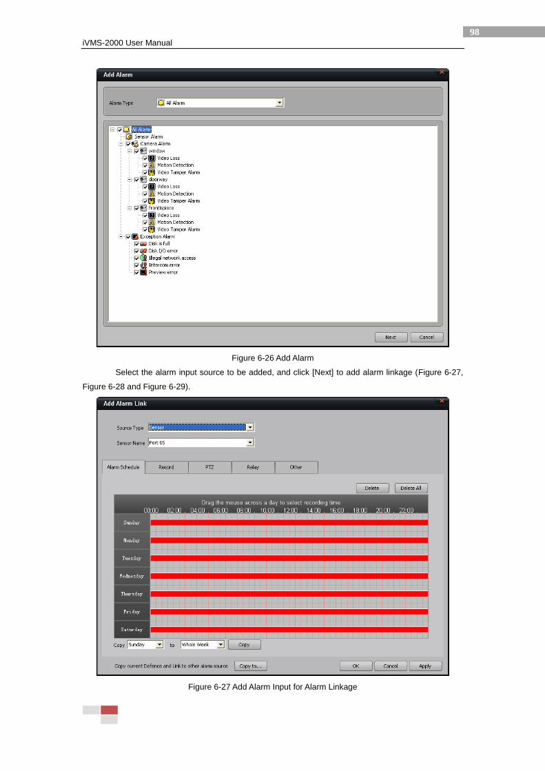
iVMS-2000 User Manual
98
Figure 6-26 Add Alarm
Select the alarm input source to be added, and click [Next] to add alarm linkage (Figure 6-27,
Figure 6-28 and Figure 6-29).
Figure 6-27 Add Alarm Input for Alarm Linkage
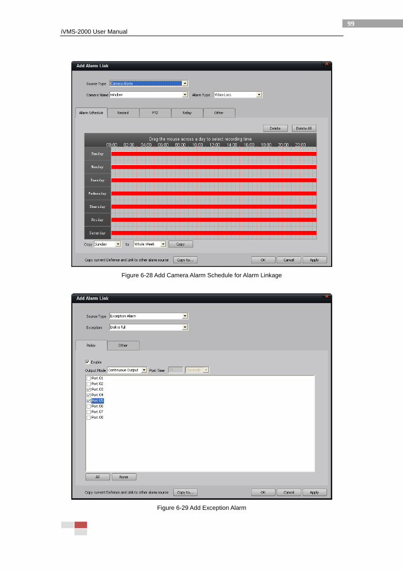
iVMS-2000 User Manual
99
Figure 6-28 Add Camera Alarm Schedule for Alarm Linkage
Figure 6-29 Add Exception Alarm
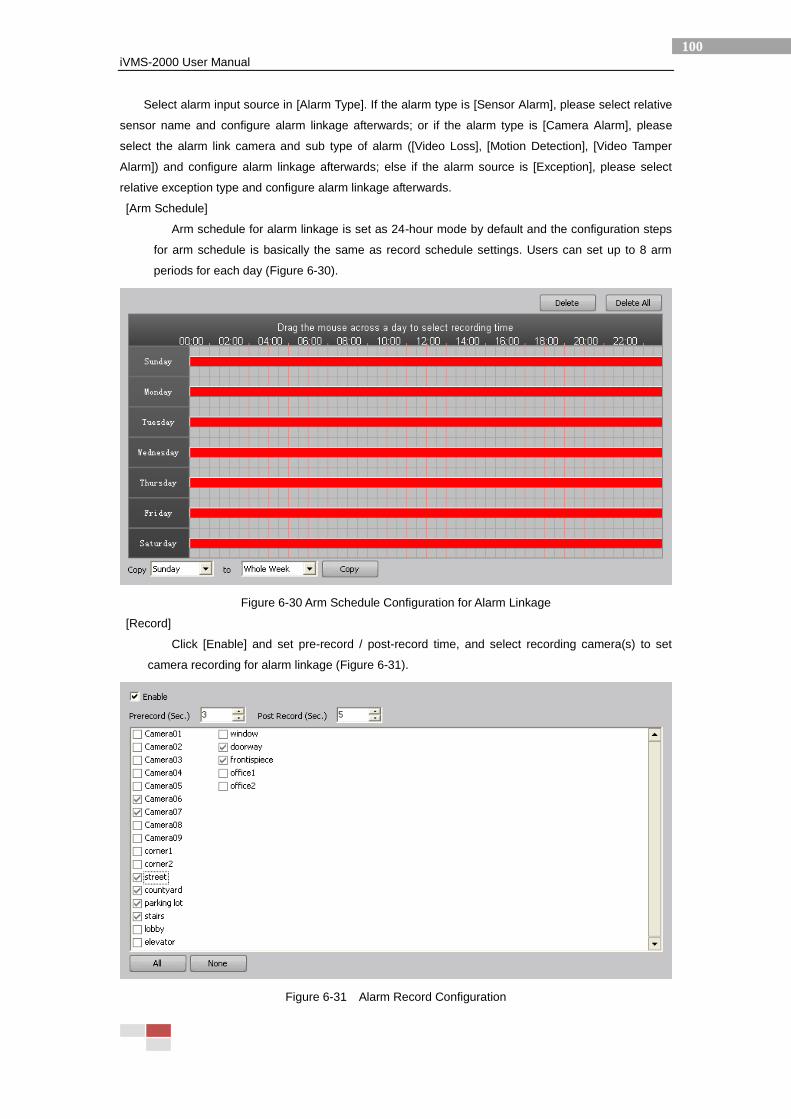
iVMS-2000 User Manual
100
Select alarm input source in [Alarm Type]. If the alarm type is [Sensor Alarm], please select relative
sensor name and configure alarm linkage afterwards; or if the alarm type is [Camera Alarm], please
select the alarm link camera and sub type of alarm ([Video Loss], [Motion Detection], [Video Tamper
Alarm]) and configure alarm linkage afterwards; else if the alarm source is [Exception], please select
relative exception type and configure alarm linkage afterwards.
[Arm Schedule]
Arm schedule for alarm linkage is set as 24-hour mode by default and the configuration steps
for arm schedule is basically the same as record schedule settings. Users can set up to 8 arm
periods for each day (Figure 6-30).
Figure 6-30 Arm Schedule Configuration for Alarm Linkage
[Record]
Click [Enable] and set pre-record / post-record time, and select recording camera(s) to set
camera recording for alarm linkage (Figure 6-31).
Figure 6-31 Alarm Record Configuration
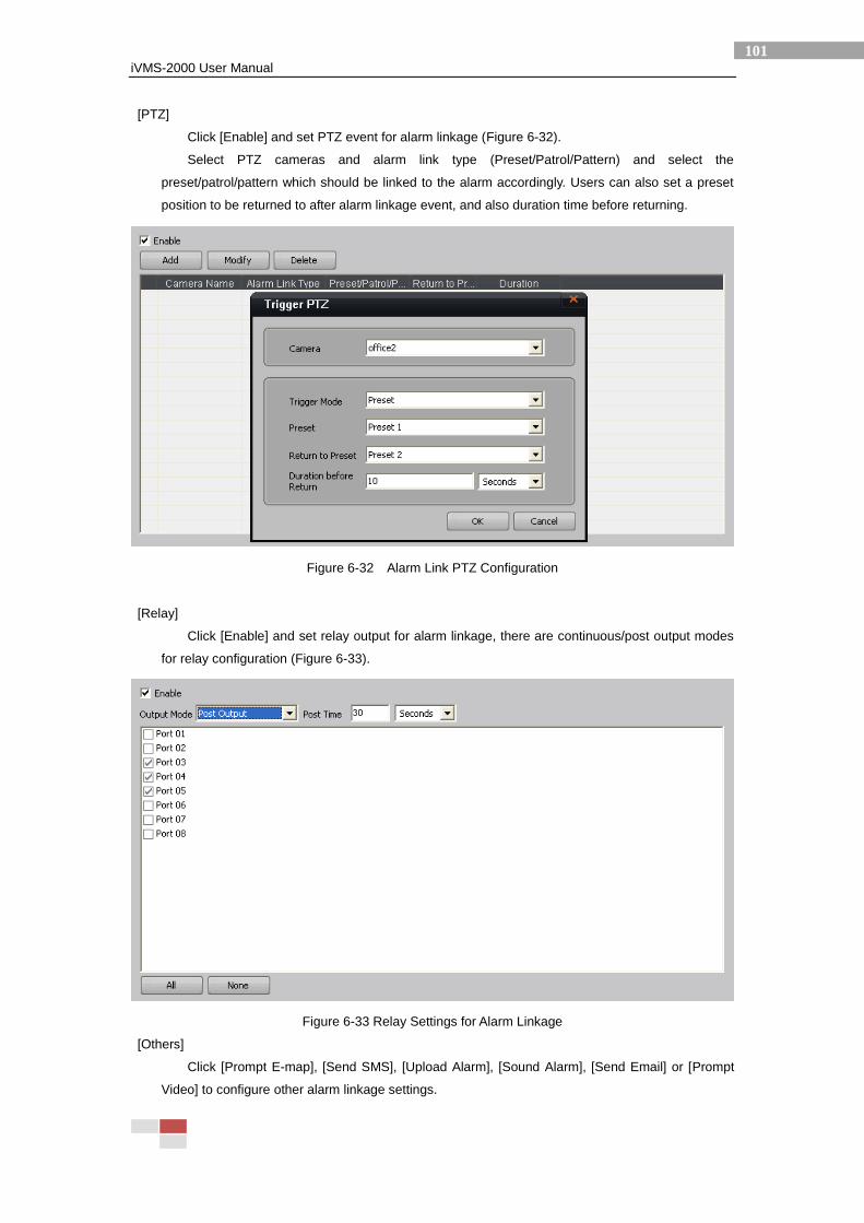
iVMS-2000 User Manual
101
[PTZ]
Click [Enable] and set PTZ event for alarm linkage (Figure 6-32).
Select PTZ cameras and alarm link type (Preset/Patrol/Pattern) and select the
preset/patrol/pattern which should be linked to the alarm accordingly. Users can also set a preset
position to be returned to after alarm linkage event, and also duration time before returning.
Figure 6-32 Alarm Link PTZ Configuration
[Relay]
Click [Enable] and set relay output for alarm linkage, there are continuous/post output modes
for relay configuration (Figure 6-33).
Figure 6-33 Relay Settings for Alarm Linkage
[Others]
Click [Prompt E-map], [Send SMS], [Upload Alarm], [Sound Alarm], [Send Email] or [Prompt
Video] to configure other alarm linkage settings.
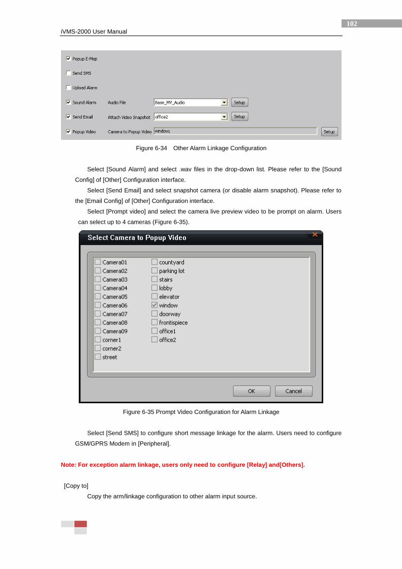
iVMS-2000 User Manual
102
Figure 6-34 Other Alarm Linkage Configuration
Select [Sound Alarm] and select .wav files in the drop-down list. Please refer to the [Sound
Config] of [Other] Configuration interface.
Select [Send Email] and select snapshot camera (or disable alarm snapshot). Please refer to
the [Email Config] of [Other] Configuration interface.
Select [Prompt video] and select the camera live preview video to be prompt on alarm. Users
can select up to 4 cameras (Figure 6-35).
Figure 6-35 Prompt Video Configuration for Alarm Linkage
Select [Send SMS] to configure short message linkage for the alarm. Users need to configure
GSM/GPRS Modem in [Peripheral].
Note: For exception alarm linkage, users only need to configure [Relay] and[Others].
[Copy to]
Copy the arm/linkage configuration to other alarm input source.
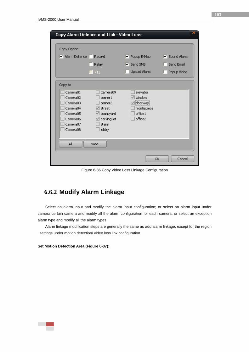
iVMS-2000 User Manual
103
Figure 6-36 Copy Video Loss Linkage Configuration
6.6.2 Modify Alarm Linkage
Select an alarm input and modify the alarm input configuration; or select an alarm input under
camera certain camera and modify all the alarm configuration for each camera; or select an exception
alarm type and modify all the alarm types.
Alarm linkage modification steps are generally the same as add alarm linkage, except for the region
settings under motion detection/ video loss link configuration.
Set Motion Detection Area (Figure 6-37):
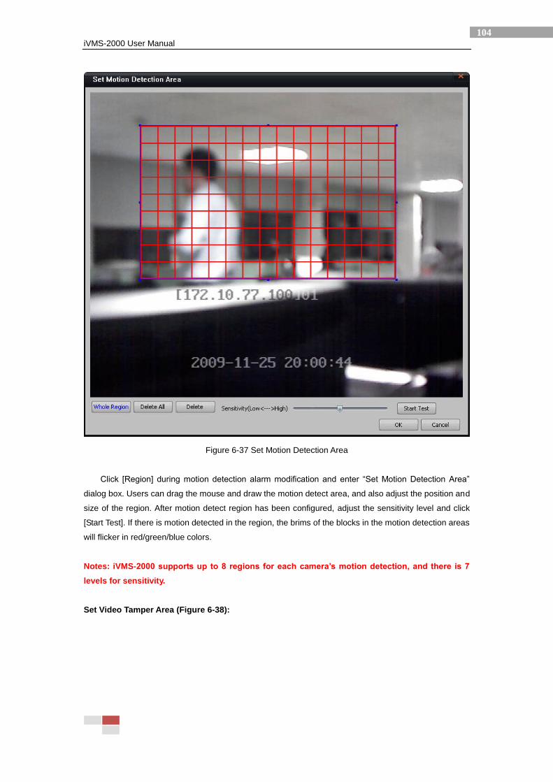
iVMS-2000 User Manual
104
Figure 6-37 Set Motion Detection Area
Click [Region] during motion detection alarm modification and enter “Set Motion Detection Area”
dialog box. Users can drag the mouse and draw the motion detect area, and also adjust the position and
size of the region. After motion detect region has been configured, adjust the sensitivity level and click
[Start Test]. If there is motion detected in the region, the brims of the blocks in the motion detection areas
will flicker in red/green/blue colors.
Notes: iVMS-2000 supports up to 8 regions for each camera’s motion detection, and there is 7
levels for sensitivity.
Set Video Tamper Area (Figure 6-38):
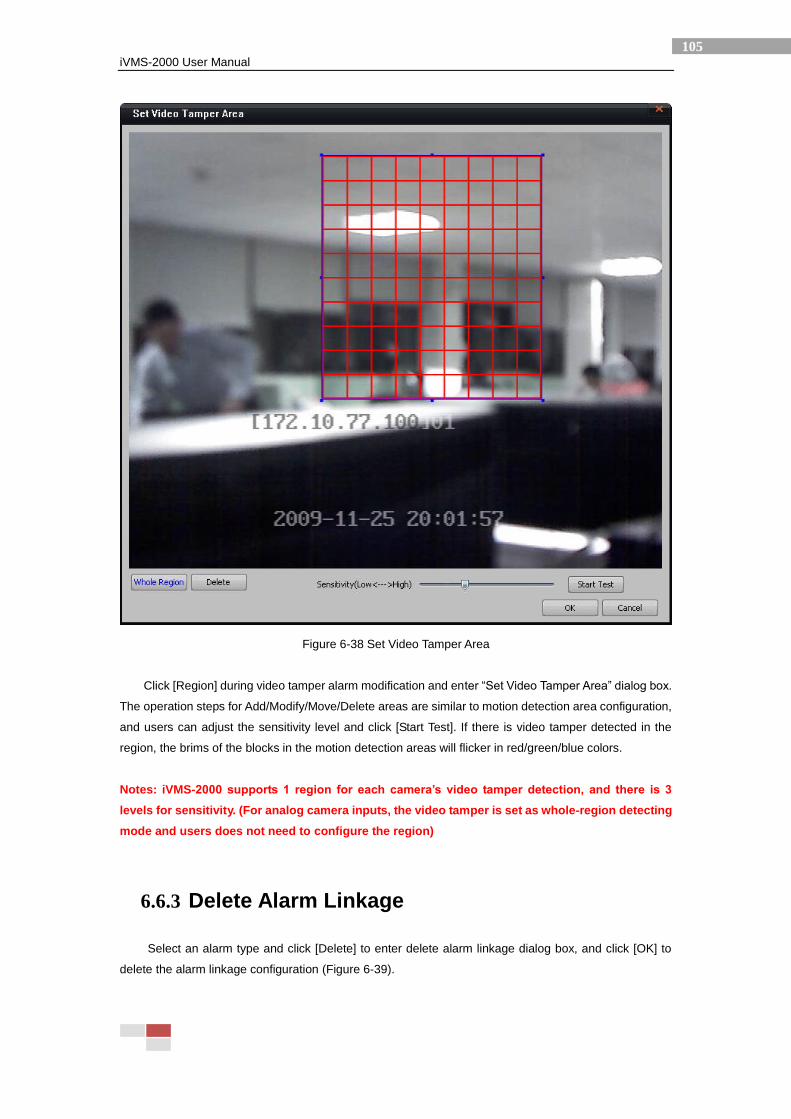
iVMS-2000 User Manual
105
Figure 6-38 Set Video Tamper Area
Click [Region] during video tamper alarm modification and enter “Set Video Tamper Area” dialog box.
The operation steps for Add/Modify/Move/Delete areas are similar to motion detection area configuration,
and users can adjust the sensitivity level and click [Start Test]. If there is video tamper detected in the
region, the brims of the blocks in the motion detection areas will flicker in red/green/blue colors.
Notes: iVMS-2000 supports 1 region for each camera’s video tamper detection, and there is 3
levels for sensitivity. (For analog camera inputs, the video tamper is set as whole-region detecting
mode and users does not need to configure the region)
6.6.3 Delete Alarm Linkage
Select an alarm type and click [Delete] to enter delete alarm linkage dialog box, and click [OK] to
delete the alarm linkage configuration (Figure 6-39).
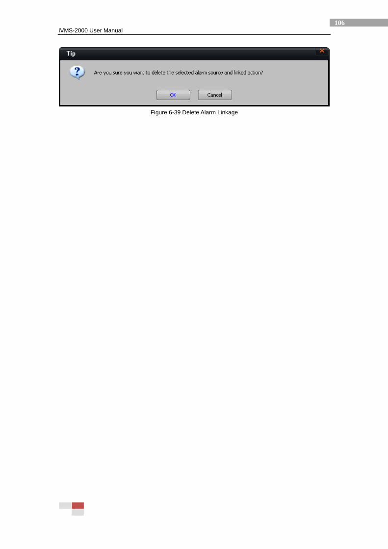
iVMS-2000 User Manual
106
Figure 6-39 Delete Alarm Linkage

iVMS-2000 User Manual
107
6.7 Peripheral
Click [Peripheral] and enter peripheral configuration interface (Figure 6-40), and configure peripheral
devices like serial port, alarm box, etc.
Figure 6-40 Peripherals Configuration Interface
iVMS-2000 User Manual
108
6.7.1 SMS Configuration
Users can configure COM port and mobile phone number to receive the short message in the SMS
configuration interface, and the SMS configuration is related to the SMS alarm linkage configuration.
A GSM/GPRS modem is required for SMS function (Please refer to the installation guide of
GSM/GPRS Modem for its configuration steps). After the modem is connected and its driver is installed,
users can read the COM port number for the modem in “Device Manage” of Windows OS. Please input
the COM port info and mobile phone number in iVMS-2000 configuration interface, and click [OK] after
testing.
Notes: The COM port for SMS cannot be duplicated with COM port for PTZ or alarm box.
6.7.2 PTZ COM Port Configuration
Users need to configure the PTZ connection port for iVMS-2000, and click [Save]. For the other PTZ
configurations, such as PTZ protocol, address and COM port data information can be configured under
Camera configuration.
Notes: The COM port for PTZ cannot be duplicated with COM port for SMS or alarm box.
6.7.3 Alarm Box Configuration
Add/ Modify/ Delete local or network alarm box.
[Add Alarm Box]
Add local sensor input and replay output (Figure 6-41) and configure COM port information,
such as sensor input port and relay output port. Users can test the I/O signals while adding alarm
box information. For [Check Sensor] function, users need to connect sensor input devices on the
alarm box; and for [Check Relay], users need to click each icon under this button to test the relay
output for the alarm box.
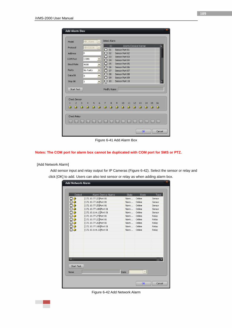
iVMS-2000 User Manual
109
Figure 6-41 Add Alarm Box
Notes: The COM port for alarm box cannot be duplicated with COM port for SMS or PTZ.
[Add Network Alarm]
Add sensor input and relay output for IP Cameras (Figure 6-42). Select the sensor or relay and
click [OK] to add. Users can also test sensor or relay as when adding alarm box.
Figure 6-42 Add Network Alarm

iVMS-2000 User Manual
110
[Modify]
Select any of the network sensor and then modify all the network sensor configuration, or
select any of the network relay and then modify all the network relay configuration, or select any of
the alarm box and then modify all the alarm box configuration.
[Delete]
Select the sensor(s), relay(s) or alarm box(es) and click [Delete] to delete the alarm settings.
Notes: Users need to click [Save] to save the modified alarm configuration before taking effect.
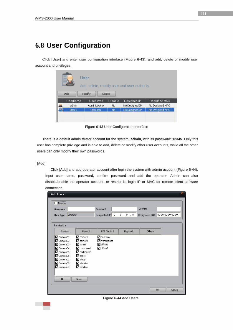
iVMS-2000 User Manual
111
6.8 User Configuration
Click [User] and enter user configuration interface (Figure 6-43), and add, delete or modify user
account and privileges.
Figure 6-43 User Configuration Interface
There is a default administrator account for the system: admin, with its password: 12345. Only this
user has complete privilege and is able to add, delete or modify other user accounts, while all the other
users can only modify their own passwords.
[Add]
Click [Add] and add operator account after login the system with admin account (Figure 6-44).
Input user name, password, confirm password and add the operator. Admin can also
disable/enable the operator account, or restrict its login IP or MAC for remote client software
connection.
Figure 6-44 Add Users
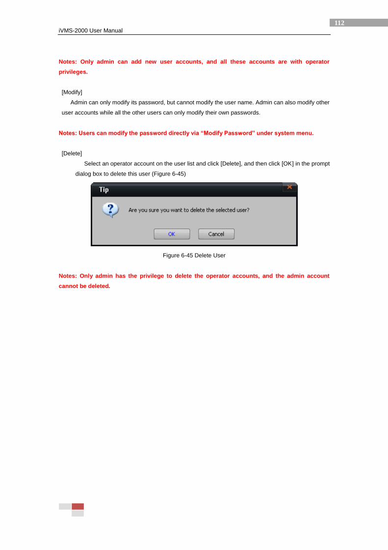
iVMS-2000 User Manual
112
Notes: Only admin can add new user accounts, and all these accounts are with operator
privileges.
[Modify]
Admin can only modify its password, but cannot modify the user name. Admin can also modify other
user accounts while all the other users can only modify their own passwords.
Notes: Users can modify the password directly via “Modify Password” under system menu.
[Delete]
Select an operator account on the user list and click [Delete], and then click [OK] in the prompt
dialog box to delete this user (Figure 6-45)
Figure 6-45 Delete User
Notes: Only admin has the privilege to delete the operator accounts, and the admin account
cannot be deleted.

iVMS-2000 User Manual
113
6.9 Others
Click [Others] to enter other configuration interface (Figure 6-46). This configuration interface is
mainly used for email and alarm audio settings, etc. Users can click the Tabs above to switch between
different setting pages.
Figure 6-46 Other Configuration Interface
[Alarm Audio]
Audio files for alarm linkage configuration. There is 4 default alarm audio files in the iVMS-2000
system, and the users can add no more than 12 audio files (Figure 6-47).
Figure 6-47 Alarm Audio Configuration
[Add]
Add alarm audio file. Click [Add] and select audio files and set its name in the prompt dialog
box (Figure 6-48), and then click [OK].
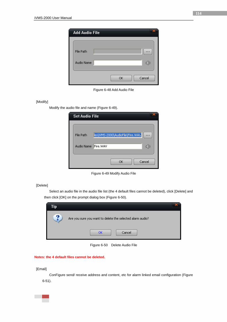
iVMS-2000 User Manual
114
Figure 6-48 Add Audio File
[Modify]
Modify the audio file and name (Figure 6-49).
Figure 6-49 Modify Audio File
[Delete]
Select an audio file in the audio file list (the 4 default files cannot be deleted), click [Delete] and
then click [OK] on the prompt dialog box (Figure 6-50).
Figure 6-50 Delete Audio File
Notes: the 4 default files cannot be deleted.
[Email]
ConFigure send/ receive address and content, etc for alarm linked email configuration (Figure
6-51).
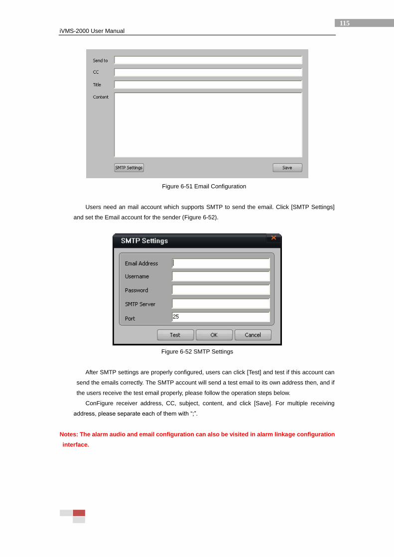
iVMS-2000 User Manual
115
Figure 6-51 Email Configuration
Users need an mail account which supports SMTP to send the email. Click [SMTP Settings]
and set the Email account for the sender (Figure 6-52).
Figure 6-52 SMTP Settings
After SMTP settings are properly configured, users can click [Test] and test if this account can
send the emails correctly. The SMTP account will send a test email to its own address then, and if
the users receive the test email properly, please follow the operation steps below.
ConFigure receiver address, CC, subject, content, and click [Save]. For multiple receiving
address, please separate each of them with “;”.
Notes: The alarm audio and email configuration can also be visited in alarm linkage configuration
interface.
iVMS-2000 User Manual
116
7 Appendix
7.1 Technical Terms
CIF
Common intermediate format, a format of color images, 352*288 pixels (for PAL system)
QCIF
Quarter Common Intermediate Format, a format of color images, 176*144 pixels (for PAL system)
DCIF
Short form of DOUBLE CIF, a format of color images, 528*384 pixels (for PAL system)
2CIF
2-times Common Intermediate Format, a format of color images, 704*288 pixels (for
PAL system)
4CIF
Four-times Common Intermediate Format, a format of color images, 704 x 576 pixels
(for PAL system)
OSD
On Screen Display
CBR
Constant Bit Rate
VBR
Variable Bit Rate
PTZ
Pan, Tilt & Zoom
USB
Universal Serial Bus
H.264
A new digital video encode standard promoted by the joint video team (JVT) which is formed by
the VCEG (Video Coding Experts Group) under ITU-T and MPEG (Moving Picture Experts Group) under
the International Organization for Standardization (ISO).
FAT32
FAT32 (File Allocation Table) is a kind of file allocation table with cluster counts held in a 4-byte
(32-bit) field. For the FAT32 subarea format, each cluster is fixed at 4 KB, and therefore greatly reduces
the waste of disk space and improves the utilization of the disk.
NTFS
NTFS is the standard file system of Windows NT and Windows NT Advanced Server network
operating system.
NTFS is going to provide reliability via the recoverable capacity (event tracing) and the hot-located
fault-tolerant characteristics; a platform to increase functionality; demand for POSIX support; and also
elimination of FAT and HPFS file system limitations.
NTSC
iVMS-2000 User Manual
117
NTSC (National Television Standards Committee) is a color TV broadcast standard with 30 fps
frame rate, and is widely used in North-America, Japan, and South-American countries.
PAL
PAL (Phase Alternation by Line) is is a color TV broadcast standard with 25 fps frame rate, and is
widely used in UK, East and Middle Asia, Europe and African countries which adopts 50Hz AC power
supply.
.WAV
Short for Waveform audio format, a kind of Digital Audio File Formats
Patrol
PTZ moving track
Preset
Preset PTZ position
PTZ
A mechanism device to pan, tilt or zoom the cameras,
Baud Rate
Baud rate is the number of bits transmitted per second, i.e. 300 bit/s stands for 300 bits are sent per
second; and if the PTZ protocol needs 4800 as baud rate, then it represents the clock cycle is 4800Hz,
and the serial port communication sampling rate is also 48000HZ. Usually the baud rate for telephone
wire is 14400, 28800 and 36600, the baud rate can be set as much higher than these values, but the
baud rate is inversely proportional to the maximum transmission distance. High bit rate is usually used for
short distance communication, i.e. GPIB device communication.
Data Bit
Data bit is a measure of the actual data bits in communication. When the computer sends a packet,
the actual data bits is not 8 digits, and the standard value is 5, 7 or 8, depending on how you want to
configure the transmission of information. For instance, the standard ASCII code is 0 to 127 (7 digits),
and the extended ASCII code is 0 to 255 (8 digits). If the data using a simple text (standard ASCII code),
then each data packet uses 7 digits information. Each package stands for 1 byte, including start / stop bit,
data bit and parity bit. As the actual data digits depend on the communication protocol, the term
"package" is for any communications.
Stop Bit
Stop bit is used to mark the last digits of the package, whose typical value is 1, 1.5 or 2. AS data
transmission is schedule on transmission lines, and each device has its own clock, it is likely that
communication between the two devices will not in complete synchronization. Thus the stop bit does not
only stand for end of the transmission, but also provides system clock synchronization checking. The
larger the stop digits, the more endurance of different clock synchronization, yet slower the data
transmission.
Parity Bit
There is a simple error detection way for serial communication which includes 4 detection mode:
even, odd, high and low. (Of course, no parity bit is also allowed.) On even and odd checking, the serial
port will set up a parity bit right, with a value of the data to keep transmission digits in even or odd number.
For example, if data is 011, then the parity bit is 0 to guarantee logic high median is even number. When
in odd check, then the parity bit is 1 so that there are three logical high digits. The high and low bit do not
actually check the data information, but only through a simple logic check. This makes receiving devices
to know if there is a noise interferes in communication or whether transmission and reception of data is
iVMS-2000 User Manual
118
not synchronized by digit status.
Hot Spot
Spot on the E-map which is linked with other E-map
Sensor (for E-map)
Spot on the E-map which is linked with alarm sensor input
Saturation
The intensity of a specific hue of color video
Brightness
Brightness is an attribute of visual perception in which a source appears to be radiating or
reflecting light.
Hue
The degree to which a stimulus can be described as similar to or different from stimuli that are
described as red, green, blue, and yellow.
Contrast
The dissimilarity or difference between color brightness
Alarm Box
Device to pick up sensor input and relay output signals
Local Display
Video output directly from the encoding device
Trigger Replay
Output alarm signals under certain interval
Serial Port
Serial port interface
Port
Port address for the protocol, an integer to represent a process
MAC
Media Access Control
Motion Detect
The whole monitoring image is divided into various small areas, among which users can select any
areas with different sensitivity level, and the movements in these areas will be detected by the camera
and trigger motion record.
Video Tamper Alarm
Alarm when video being tampered
Privacy Mask
Mask certain area of the image.
Pre-record Time
Save recording in a short duration before the scheduled start time
Post-record Time
Save recording in a short duration after the scheduled start time
Bit Rate
Bit rate is the bit number per unit time in data transmission, usually using the unit of kbps (kbit per
second), or to say, the sampling rate. The highest the sampling rate per unit time, the more precise the
data information, and the more close the transmitted file to the original file. But the file size will increase
as the sampling rate increases, thus almost all the encoding standard is focus on acquiring least
iVMS-2000 User Manual
119
distortion with smallest video size, and the CBR (Constant Bit Rate) and VBR (Variable Bit Rate) is
originated from it. On the side of audio encoding, the higher the bit rate, the less the compression ratio
and sound distortion, but the encoding algorithm is different for different audio players, and the bit rate is
not the only measure for audio quality. For instance, it is not exactly that the sound quality of lower bit
rate mp3 files is not as good as higher bit rate wma file, especially after using VBR encoding. In some
occasions, VBR can even achieve better audio quality than CBR on the same encoder.
Stream Type
Compressed stream type containing both video stream and video & audio stream.
Video & Audio Stream
Multimedia stream that contains both video and audio information
Video Stream
Pure video stream
Video Frame Rate
Video frames per second
Frame Rate
FPS, stands for frames per second, the value of information data flow of dynamic images.
Continuous playing of static images will enable the feeling of dynamic video, and the movements will be
much fluent as fps value raises.
Frame Type
I frame (Intra code frame) is intra-frame encoding frame, P(Predicted frame)is forward forecast
coding frame according to I or the previous P frame, B(Bi-direction frame)is interpolation frame calculated
by neighboring I, P or P, P frames.
Dual Stream
It means a camera of video images passing through the video coder, and output 2 independent bit
streams. The resolution, frame rate, bit rate and other parameters of output bit stream can be set
independently. The output dual steam can meet different demands, for example, one for hard disk
storage and the other for network transmission.
Watermark
It means to insert hidden information, i.e. digits, serial number, characters, logo, etc into digitalized
multimedia files by signal processing technology. Such marks are usually invisible, and can only be
extracted by specially designed detectors to get the purpose of copyright protection.
TV Wall
TV wall is formed by integration of multiple display units. A large-screen TV wall system is
consisted of TV wall units, TV wall processor and TV wall interfaces. Generally speaking, any display unit
can be adopted to TV wall system. TV wall processor can do image processing (divide and enlarge) to a
complete standard video input signal and output to M*N standard display devices, and the TV wall
interfaces is device for signal transforming and output between signal input and TV wall output.
Resolution
Resolution types include display resolution, image resolution and pixel resolution.
Display resolution is the largest area shown on the screen in particular display mode, in
representation of horizontal and vertical pixels.
Image resolution refers to the size of digital image, also represented by horizontal and vertical pixels.
If the image resolution is bigger than display resolution, then some images can’t be displayed.
Pixel resolution refers to a ratio of pixel’s width and length. Different ratio will cause the deformation
iVMS-2000 User Manual
120
of images.
Common Image resolution modes in digital surveillance are:
PAL: QCIF (174*144), CIF (352*288), 2CIF (704*288), DCIF (528*384), FULL D1 (704*576) , VGA
(640*480) , SVGA (800*600) , UXGA (1600*1200) , HD720P (1280*720) .
NTSC: QCIF (174*120), CIF (352*240), 2CIF (704*240), DCIF (528*320), FULL D1 (704*480), VGA
(640*480), SVGA (800*600), UXGA (1600*1200), HD720P (1280*720).
Common VGA resolution: 640*480, 800*600, 1024*768,1280*1024, etc.
Dynamically Adjust Encoding Parameters
The dynamically adjusted encoding parameters can take effect at once without pausing or restarting
network transmitting and recording.
In surveillance system, for static monitoring scene, video can be recorded in low bit rate through
reducing resolution, image quality, bit rate and frame rate, while changing of images require higher
resolution , bit rate and frame rate of video, etc to get high quality video stream. Since the above
parameters can be dynamically modified, continuous images can be maintained without switching files
frequently. And it does not only meet the requirement of high-quality images at critical moments, but also
save the disk space and network bandwidth.
File System Fragment
When a file is recorded and scattered in discontinuous clusters, the content in the discontinuous
clusters is called file system fragments. When contents of the files in the hard disk were frequently
deleted and re-written, the file system fragments will appear easily, and thus increase the seeking delay
and rotation delay of the hard disk, and then affect its efficiency and life-span.
If the file is defined beforehand and pre-allocated to consecutive clusters, the generating of file
system fragments can be completely avoided.