Embed Size (px)
Citation preview

Revised Implementor's Guide for the ITU-T H.320 Recommendation series (H.221, H.224, H.230, H.242, H.243)
__________________
IntroductionThis document is a text revision of the Implementor’s Guide for H.320 series recommendations. Changes are made against the 05/99 revision of H.221, H.230 and H.242, and the 02/2000 revision of H.224 and H.243.
Note that Section 7 has been renumbered as follows:
7.1 Technical and editorial corrections to ITU-T Recommendation H.221
7.2 Technical and editorial corrections to ITU-T Recommendation H.224
7.3 Technical and editorial corrections to ITU-T Recommendation H.230
7.4 Technical and editorial corrections to ITU-T Recommendation H.242
7.5 Technical and editorial corrections to ITU-T Recommendation H.243
Changes from the previous published version appear in the following sections:
1. 7.2.1 New section 11 (Q1-A11)

- 2 -
Implementor's Guide for the ITU-T H.320 Recommendation series - Narrow-band visual telephone systems and terminal equipment
AbstractThis document is a compilation of reported defects identified with the 1997-2000 editions of the ITU-T H.320-series Recommendations. It is intended to be read in conjunction with the Recommendations to serve as an additional authoritative source of information for implementors. The changes, clarifications and corrections defined herein are expected to be included in future versions of affected H.320-series Recommendations.
Contact informationITU-T Study Group 16/Question 1 Rapporteur
Patrick Luthi
PictureTel Corp.
100 Minuteman Road
Andover, MA 01810
USA
Tel: +1 978 292 5000Fax: +1 978 292 3309Email: [email protected]
ITU-T Recommendation H.320-series Editor
Patrick Luthi Tel: +1 978 292 5000Fax: +1 978 292 3309Email: [email protected]
Document history
Revision Date Description
1 18 February 2000 Initial version - Reviewed at ITU-T Study Group 16 Rapporteurs meeting.
2 17 November 2000 Second version - Completed at ITU-T Study Group 16 Rapporteurs meeting.
3 8 June 2001 Third version - Completed at ITU-T Study Group 16 Rapporteurs meeting.
- 3 -
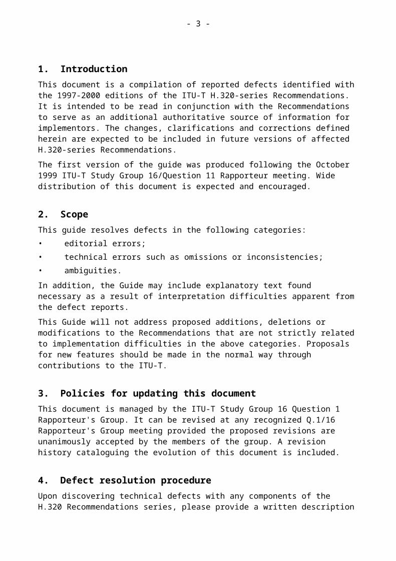
1. IntroductionThis document is a compilation of reported defects identified with the 1997-2000 editions of the ITU-T H.320-series Recommendations. It is intended to be read in conjunction with the Recommendations to serve as an additional authoritative source of information for implementors. The changes, clarifications and corrections defined herein are expected to be included in future versions of affected H.320-series Recommendations.
The first version of the guide was produced following the October 1999 ITU-T Study Group 16/Question 11 Rapporteur meeting. Wide distribution of this document is expected and encouraged.
2. ScopeThis guide resolves defects in the following categories:• editorial errors;• technical errors such as omissions or inconsistencies;• ambiguities.
In addition, the Guide may include explanatory text found necessary as a result of interpretation difficulties apparent from the defect reports.
This Guide will not address proposed additions, deletions or modifications to the Recommendations that are not strictly related to implementation difficulties in the above categories. Proposals for new features should be made in the normal way through contributions to the ITU-T.
3. Policies for updating this documentThis document is managed by the ITU-T Study Group 16 Question 1 Rapporteur's Group. It can be revised at any recognized Q.1/16 Rapporteur's Group meeting provided the proposed revisions are unanimously accepted by the members of the group. A revision history cataloguing the evolution of this document is included.
4. Defect resolution procedureUpon discovering technical defects with any components of the H.320 Recommendations series, please provide a written description directly to the editors of the affected Recommendations with a copy to the Q.1/16 Rapporteur. The template for a defect report is enclosed. Contact information for these parties is included in this document. Return contact information should also be supplied so a dialogue can be established to resolve the matter and an appropriate reply to the defect report can be conveyed. This defect resolution process is open to anyone interested in H.320-series Recommendations. Formal membership in the ITU is not required to participate in this process.
5. ReferencesThis document refers to the following H.320-series Recommendations:
– ITU-T Recommendation H.221 (1999), Frame Structure for a 64 to 1920 kbit/s channel in audiovisual teleservices.

- 4 -
– ITU-T Recommendation H.224 (2000), A real time control protocol for simplex applications using the H.221 LSD/HSD/MLP channels
– ITU-T Recommendation H.230 (1999), Frame-synchronous control and indication signals for audiovisual systems
– ITU-T Recommendation H.242 (1999), System for establishing communication between audiovisual terminals using digital channel up to 2 Mbit/s.
– ITU-T Recommendation H.243 (2000), Procedures for establishing communication between three or more audiovisual terminals using digital channels up to 1920 kbit/s
– ITU-T Recommendation H.320 (1999), Narrow-band visual telephone systems and terminal equipment.
– ITU-T Recommendation T.35 (2000), Procedure for the allocation of ITU-T defined codes for non-standard facilities
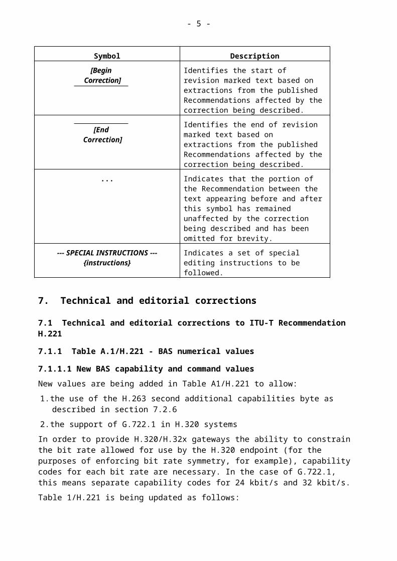
6. NomenclatureIn addition to traditional revision marks, the following marks and symbols are used to indicate to the reader how changes to the text of a Recommendation should be applied:
Symbol Description
[Begin Correction] Identifies the start of revision marked text based on extractions from the published Recommendations affected by the correction being described.
[End Correction]Identifies the end of revision marked text based on extractions from the published Recommendations affected by the correction being described.
... Indicates that the portion of the Recommendation between the text appearing before and after this symbol has remained unaffected by the correction being described and has been omitted for brevity.
--- SPECIAL INSTRUCTIONS --- {instructions}
Indicates a set of special editing instructions to be followed.
7. Technical and editorial corrections
7.1 Technical and editorial corrections to ITU-T Recommendation H.221
7.1.1 Table A.1/H.221 - BAS numerical values
7.1.1.1 New BAS capability and command values
New values are being added in Table A1/H.221 to allow:
1. the use of the H.263 second additional capabilities byte as described in section 7.2.6
- 5 -
2. the support of G.722.1 in H.320 systems
In order to provide H.320/H.32x gateways the ability to constrain the bit rate allowed for use by the H.320 endpoint (for the purposes of enforcing bit rate symmetry, for example), capability codes for each bit rate are necessary. In the case of G.722.1, this means separate capability codes for 24 kbit/s and 32 kbit/s.
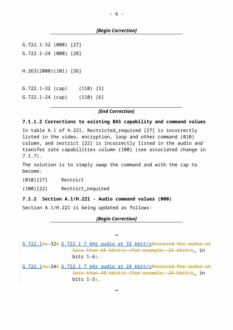
Table 1/H.221 is being updated as follows:
[Begin Correction]
G.722.1-32 (000) [27]
G.722.1-24 (000) [28]
H.263(2000) (101) [26]
G.722.1-32 (cap) (110) [5]
G.722.1-24 (cap) (110) [6]
[End Correction]
7.1.1.2 Corrections to existing BAS capability and command values
In table A.1 of H.221, Restricted_required [27] is incorrectly listed in the video, encryption, loop and other command (010) column, and restrict [22] is incorrectly listed in the audio and transfer rate capabilities column (100) (see associated change in 7.1.7).
The solution is to simply swap the command and with the cap to become:
(010)[27] Restrict
(100)[22] Restrict_required
7.1.2 Section A.1/H.221 - Audio command values (000)
Section A.1/H.221 is being updated as follows:
[Begin Correction]
…
G.722.1Au-32k G.722.1 7 kHz audio at 32 kbit/sReserved for audio at less than 48 kbit/s (for example, 32 kbit/s, in bits 1-4).
G.722.1Au-24k G.722.1 7 kHz audio at 24 kbit/sReserved for audio at less than 48 kbit/s (for example, 24 kbit/s, in bits 1-3).
…
[End Correction]
7.1.3 Section A.5/H.221 - Audio capabilities (100)
- 6 -
Section A.5/H.221 is being updated as follows:
…
G.722-64 Capable of decoding audio to Recommendation G.722 (mode 1) and to Recommendation G.711.
G.722-48 Capable of decoding audio to Recommendation G.722 (modes 1, 2, 3) and to Recommendation G.711.
[Begin Correction]
G.722.1-32 (cap) Capable of decoding audio to Recommendation G.722.1 at 32 kbit/s and to Recommendation G.711.
G.722.1-24 (cap) Capable of decoding audio to Recommendation G.722.1 at 24 kbit/s and to Recommendation G.711.
…
[End Correction]
7.1.4 Bit Position for G.722.1 audio
This new section is being added at the end of Section 4.2 (encoded audio streams) as follows:
[Begin Correction]
…
G.722.1 audio
G.722.1 provides two bit rates, 24 kbit/s or 32 kbit/s, and uses a frame size of 20ms. This results in either 480 bits (60 octets) or 640 bits (80 octets) in any one frame respectively. The bitrate may be changed at any 20 ms audio frame boundary. Alignment of H.221 audio mode changes with a submultiframe boundary is required by section 3.2/H.221.
Figure 1 & 2 illustrate the bit allocation of the two G.722.1 frames for a bitrate of 32 kbit/s and 24 kbit/s respectively.

- 7 -
Figure 1 - Bit positions for G.722.1 audio at 32 kbit/s
H.221
FrameSub-
ChannelBit #
Sub-Channel
1 2 3 4 5 6 7 8
1 1 2 3 4 FAS
2 5 6 7 8 FAS
3 9 10 11 12 FAS
4 13 14 15 16 FAS
First 5 ... ... ... ... FAS
H.221 6 FAS
Frame 7 FAS
8 FAS
9
...
80 317 318 319 320
81 321 322 323 324 FAS
82 ... ... ... ... FAS
83 FAS
84 FAS
Second 85 FAS
H.221 86 FAS
Frame 87 FAS
88 FAS
89
...
160 637 638 639 640

- 8 -
Figure 2 - Bit positions for G.722.1 audio at 24 kbit/s
[End Correction]
7.1.5 Clarifications to include revised T.35 country codes
The revised Recommendation T.35 (2000) extends the number of possible country codes to allow more than 254 countries. This is being achieved by introducing a second byte for new countries being reached by an escape code in the first byte of “1111 1111” (0xFF). Countries defined in the first byte are listed in Annex A/T.35 and countries defined in the second byte are listed in Annex B/T.35.
T.35 country codes are used by NS-cap and NS-comm as described in section A.9 - Escape table values (111). In footnote 4, the following text should be added:
[Begin Correction]
4 Country code consists of two bytes, the first being according to Recommendation T.35 Annex A. The second byte is assigned nationally, unless the first byte is 1111 1111, in which case the second byte shall contain the country code according to T.35 Annex B.and tThe terminal manufacturer code consist of two bytes are assigned nationally.
H.221
FrameBit # Sub-Channel
1 2 3 4 5 6 7 8
1 1 2 3 FAS
2 4 5 6 FAS
3 7 8 9 FAS
4 10 11 12 FAS
First 5 ... ... ... FAS
H.221 6 FAS
Frame 7 FAS
8 FAS
9
...
80 218 219 220
81 221 222 223 FAS
82 224 225 226 FAS
83 ... ... ... FAS
84 FAS
Second 85 FAS
H.221 86 FAS
Frame 87 FAS
88 FAS
89
...
160 478 479 480

- 9 -
[End Correction]
7.1.6 Changes to section A.6/H.221 – Video, MBE and encryption capabilities (101)
Explanatory text is being added to section A.6 to describe the new “H.263 (2000)” capability. Editorial corrections are made to the existing text to synchronize it with the values of table A.1/H.221.
[Begin Correction]
…
4/29.97 Can decode video, having a minimum picture interval of 4/29.97 seconds, to Recommendation H.261.
H.263(2000) Can accept <H.262/H.263> MBE with second additional H.263 capabilities as described in section 5.2.4.6/H.242.
Vid-imp(R) Reserved for future improved recommended video algorithm.
Video-ISOMPEG-1 Can decode video to ISO/IEC 11172-2 ("MPEG-1").
Esc-CF Capability to accept escape code (111) [0].
Encryp. Capable of handling signals on the ECS channel.
MBE-cap Can handle multiple-byte extensions messages in the BAS position, those beginning with codes in the range (111) [25-31], in addition to other values.
Esc-CF Capability to accept escape code (111) [0].
Encryp. Capable of handling signals on the ECS channel.
…
[End Correction]
7.1.7 Changes to section A.7/H.221 - Transfer-rate capabilities (100)
The text in section A.3 correctly describes the [restrict] command, but the text in section A.7 needs to be changed from [restrict] to [restrict_required] (see associated change in 7.1.1.2). The text of section A.7 is corrected as follows:
[Begin Correction]
…
Restrict_required Can work only at p 56 kbit/s, rate-adapted to p 64 kbit/s by moving the SC to bit position 7 and setting bit 8 to "one" in every channel or time-slot; a constant "one", however, may be set in bit 8 if it is known by out-of-band signalling prior to the connection that the restriction exists; this code has the effect of forcing the remote terminal to work in the p 56 kbit/s mode (see Annex B).

- 10 -
…
[End Correction]
7.2 Technical and editorial corrections to ITU-T Recommendation H.224
7.2.1 New section 11 – Generic Capability Object Identifier
To allow the usage of H.281 FECC in H.323, a new section 11 is being added to H.224 as follows:
[Begin Correction]
11. Generic Capability Object Identifier
The object identifier shown in Table 2 shall be used to identify Recommendation H.224 in the signaling procedures of Recommendation H.245.
Table 2/H.224 – Generic Capability identifier
Capability name ITU-T Recommendation H.224
Capability class Data protocolCapability identifier type StandardCapability identifier value itu-t(0) recommendation(0) h(8) 224 generic-
capabilities (1) 0Capability parameter type No parametersMaxBitRate Not used
[End Correction]
7.3 Technical and editorial corrections to ITU-T Recommendation H.230
To support a “videoBadMBs” C&I related to video in H.320 systems, a new BAS capability and command along with associated text need to be added to Recommendation H.230.
To support H.263 Annex U and Annex W, three new messages are introduced, and the associated text is added to the Reccommendation H.230.
7.3.1 Table 1/H.230
A new capability value is being added in Table 1/H.230 (by using a previously “reserved” value).
An editorial correction is being made by replacing the text “Reserved” by VSTRDENCLVL in value [21] (as defined in table 4/H.230 and in section 3.1.9). Table 1/H.230 is updated as follows:

- 11 -
[Begin Correction]
(000) [21] VSTRDENCLVL X X X X 3.1…
[24] VBMBC X X X X 3.1[25]-[30] Reserved for video-related symbols
[End Correction]
7.3.2 Table 2/H.230 - Values assigned to type identification bytes in MBE messages
Four new MBE messages are being added in Table 2/H.230 (by using a previously “reserved” value):
[Begin Correction]
0001 0010 <videoBadMBs>
0001 0011 <lostPicture>
0001 0100 <recoveryReferencePicture>
0001 0101 <lostPartialPicture>
[End Correction]
7.3.3 Table 4/H.230 - Occupancy of escape table reached from (111) [17] of Table A.1/H.221
A new capability value is being added in Table 4/H.230 (as already described in Table 1/H.230):
[Begin Correction]
(000) [24] VBMBC (cap)
[End Correction]
7.3.4 Section 3.1/H.230 - C&I related to video
The following new sections 3.1.19, 3.1.20, 3.1.21, 3.1.22, and 3.1.23 are inserted at the end of H.230 section 3.1:
[Begin Correction]
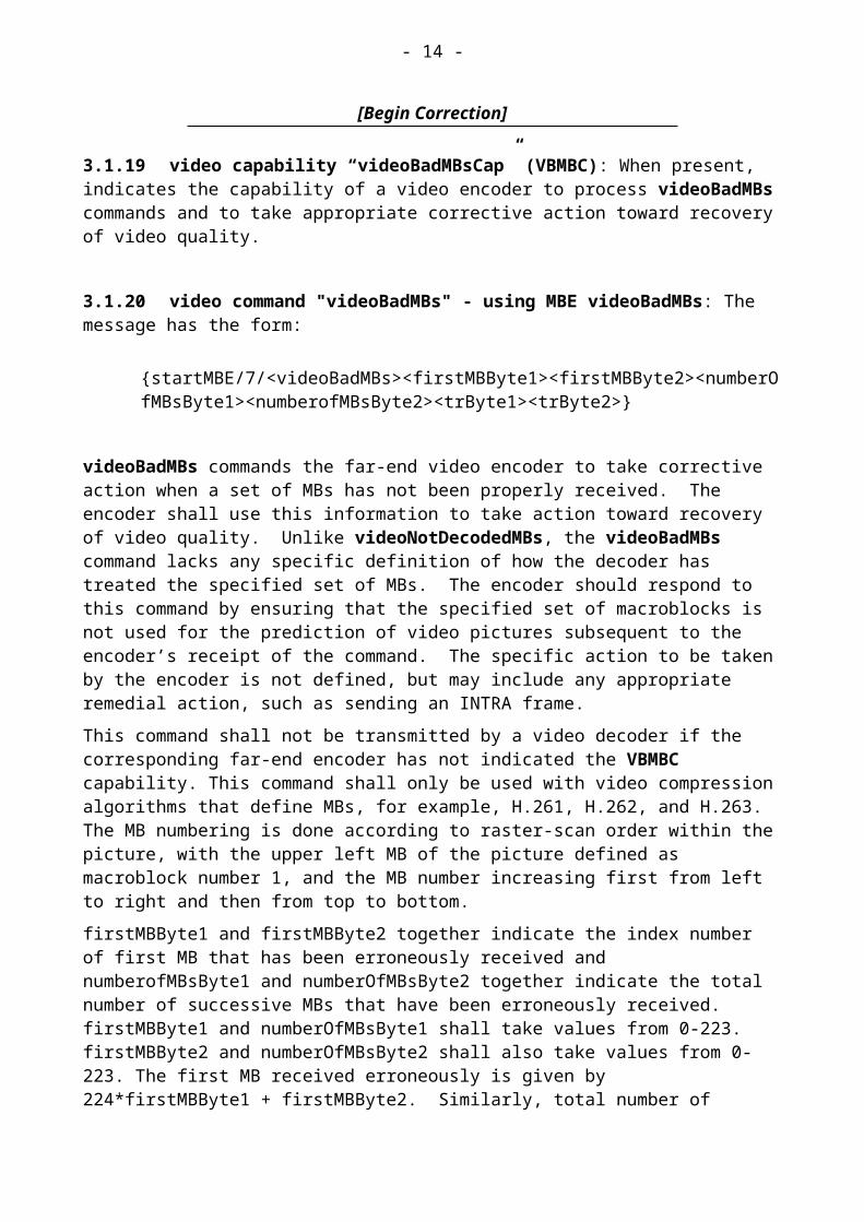
3.1.19 video capability “videoBadMBsCap” (VBMBC): When present, indicates the capability of a video encoder to process videoBadMBs commands and to take appropriate corrective action toward recovery of video quality.

- 12 -
3.1.20 video command "videoBadMBs" - using MBE videoBadMBs: The message has the form:
{startMBE/7/<videoBadMBs><firstMBByte1><firstMBByte2><numberOfMBsByte1><numberofMBsByte2><trByte1><trByte2>}
videoBadMBs commands the far-end video encoder to take corrective action when a set of MBs has not been properly received. The encoder shall use this information to take action toward recovery of video quality. Unlike videoNotDecodedMBs, the videoBadMBs command lacks any specific definition of how the decoder has treated the specified set of MBs. The encoder should respond to this command by ensuring that the specified set of macroblocks is not used for the prediction of video pictures subsequent to the encoder’s receipt of the command. The specific action to be taken by the encoder is not defined, but may include any appropriate remedial action, such as sending an INTRA frame.
This command shall not be transmitted by a video decoder if the corresponding far-end encoder has not indicated the VBMBC capability. This command shall only be used with video compression algorithms that define MBs, for example, H.261, H.262, and H.263. The MB numbering is done according to raster-scan order within the picture, with the upper left MB of the picture defined as macroblock number 1, and the MB number increasing first from left to right and then from top to bottom.
firstMBByte1 and firstMBByte2 together indicate the index number of first MB that has been erroneously received and numberofMBsByte1 and numberOfMBsByte2 together indicate the total number of successive MBs that have been erroneously received. firstMBByte1 and numberOfMBsByte1 shall take values from 0-223. firstMBByte2 and numberOfMBsByte2 shall also take values from 0-223. The first MB received erroneously is given by 224*firstMBByte1 + firstMBByte2. Similarly, total number of successive MBs that have been erroneously received is given by 224*numberofMBsByte1 + numberofMBsByte2. The decoder shall ensure that the first referenced and the total number of successive MBs are within the valid range of the video compression algorithm in use. The encoder should ignore the message if values outside the valid range are received.
The temporal reference of the picture containing erroneously received MBs is indicated by trByte1 and trByte2 which shall take values from 0-223. The temporal reference is given by 224*trByte1 + trByte2. The decoder shall ensure that the temporal reference is valid for the video compression algorithm in use. The encoder should ignore the message if a value outside the valid range is received.
3.1.21 video command "lostPicture" - using MBE lostPicture: The message has the form:{startMBE/3/<lostPicture><Byte1><Byte2>}, where the most significant bits of Byte1 and Byte2 must be set to 0 by the transmitter.
lostPicture message commands the far-end video encoder to take corrective action due to the loss or corruption of the indicated pictures. The message body contains two bytes. The two bytes together represent two parameters: shortOrLongTermPictureIndication, and picNumberOrIndex. shortOrLongTermPictureIndication = (Byte1 >> 6) & 0x1;picNumberOrIndex = ((Byte1 & 0x7) << 7) | (Byte2 & 0x7F);

- 13 -
The first parameter indicates the lost picture is a short-term picture or long-term picture. If shortOrLongTermPictureIndication is 1, the lost picture is a short-term picture, and picNumberOrIndex represents the picture number of the lost picture. If shortOrLongTermPictureIndication is 0, the lost picture is a long-term picture, picNumberOrIndex represents the long-term picture index of the lost picture. An encoder capable of Annex U/H.263 (Enhanced Reference Picture Selection, with or without sub-picture removal) and/or Annex.W.6.3.12/H.263 (Picture Number) shall be capable of understanding this message and taking corrective action.
3.1.22 video command "recoveryReferencePicture" - using MBE recoveryReferencePicture: The message has the form:
{startMBE/3/<recoveryReferencePicture><Byte1><Byte2>}, where the most significant bits of Byte1 and Byte2 must be set to 0 by the transmitter.
recoveryReferencePicture message commands the far-end encoder to use only the indicated pictures for prediction. The message body contains two Bytes, which together represent two parameters: shortOrLongTermPictureIndication, and picNumberOrIndex. shortOrLongTermPictureIndication = (Byte1 >> 6) & 0x1;picNumberOrIndex = ((Byte1 & 0x7) << 7) | (Byte2 & 0x7F);
The first parameter indicates the requested picture is a short-term picture or long-term picture. If shortOrLongTermPictureIndication is 1, the request picture is a short-term picture, and picNumberOrIndex represents the picture number of the requested picture. If shortOrLongTermPictureIndication is 0, the requested picture is a long-term picture, picNumberOrIndex represents the long-term picture index of the requested picture. An encoder capable of Annex U/H.263 (Enhanced Reference Picture Selection, with or without sub-picture removal) and/or Annex.W.6.3.12/H.263 (Picture Number) shall be capable of understanding this message and taking corrective action. It may be sent from a decoder that considers the indicated pictures to have been received and decoded correctly, and considers other (unspecified) pictures to have been corrupted by transmission.
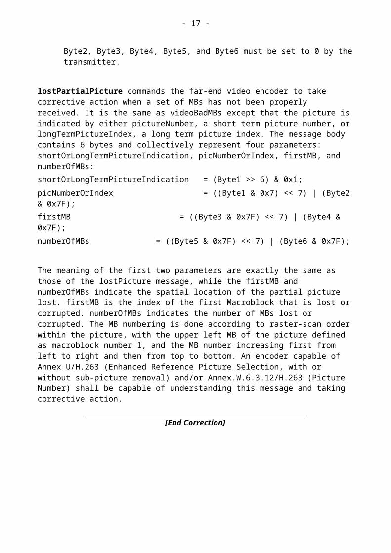
3.1.23 video command "lostPartialPicture" - using MBE lostPartialPicture: The message has the form:
{startMBE/7/<lostPartialPicture><Byte1><Byte2><Byte3><Byte4><Byte5><Byte6>}, where the most significant bits of Byte1, Byte2, Byte3, Byte4, Byte5, and Byte6 must be set to 0 by the transmitter.
lostPartialPicture commands the far-end video encoder to take corrective action when a set of MBs has not been properly received. It is the same as videoBadMBs except that the picture is indicated by either pictureNumber, a short term picture number, or longTermPictureIndex, a long term picture index. The message body contains 6 bytes and collectively represent four parameters: shortOrLongTermPictureIndication, picNumberOrIndex, firstMB, and numberOfMBs:shortOrLongTermPictureIndication = (Byte1 >> 6) & 0x1;
- 14 -
picNumberOrIndex = ((Byte1 & 0x7) << 7) | (Byte2 & 0x7F);firstMB = ((Byte3 & 0x7F) << 7) | (Byte4 & 0x7F);numberOfMBs = ((Byte5 & 0x7F) << 7) | (Byte6 & 0x7F);
The meaning of the first two parameters are exactly the same as those of the lostPicture message, while the firstMB and numberOfMBs indicate the spatial location of the partial picture lost. firstMB is the index of the first Macroblock that is lost or corrupted. numberOfMBs indicates the number of MBs lost or corrupted. The MB numbering is done according to raster-scan order within the picture, with the upper left MB of the picture defined as macroblock number 1, and the MB number increasing first from left to right and then from top to bottom. An encoder capable of Annex U/H.263 (Enhanced Reference Picture Selection, with or without sub-picture removal) and/or Annex.W.6.3.12/H.263 (Picture Number) shall be capable of understanding this message and taking corrective action.
[End Correction]
7.4 Technical and editorial corrections to ITU-T Recommendation H.242
7.4.1 Table 5/H.242 - BAS capabilities that can be included in a valid capability set
Table 5/H.242 is being updated as follows:
[Begin Correction]
…
[End Correction]b) See Appendix VII for interpretation of received audio capabilities.
7.4.2 Appendix 6 - Hierarchical capability BAS codes
Appendix 6 is being updated as follows:
[Begin Correction]
The following capability codes are hierarchically structured:
G.711 (A or or both) < G.722-64 < G.722-48
G.711 (A or or both) < G.728
G.711 (A or or both) < G.723.1
Audio Absent or One or more valuesb) from A-law, m-law, G.722-48, G.722-64, G.728, G.723.1, G.729, G.722.1-24, G.722.1-32

- 15 -
G.711 (A or or both) < G.729
G.711 (A or or both) < G.722.1-24
G.711 (A or or both) < G.722.1-32
…
[End Correction]
Note that, while they have not been included previously, G.723.1 and G.729 have been now added to the list for completeness.
7.4.3 Clarifications to include revised T.35 country codes
In Appendix III, two sections are affected by the extension of T.35 country codes (see details in section 7.1.5).
7.4.3.1 Section III.2 - Subsequent capability exchange, including MBE capability message
Section III.2 is updated as follows:
[Begin Correction]
…
{M} Information will be M-bytes
{byte 1} Country code according to Recommendation T.35 Annex A
{byte 2} Country code assigned nationally, unless the first byte is 1111 1111, in which case this field shall contain the country code according to T.35 Annex B
{bytes 3, 4} Manufacturer code (Company XYZ)
{bytes 5-M} Type identity
…
[End Correction]
7.4.3.2 Section III.3 - Mode switch to non-standard mode using MBE command
Section III.3 is updated as follows:
[Begin Correction]
…
{N} Information will be N-bytes
{byte 1} Country code according to Recommendation T.35 Annex A
{byte 2} Country code assigned nationally, unless the first byte is 1111 1111, in which case this field shall contain the country code according to T.35 Annex B
{bytes 3, 4} Manufacturer code (Company XYZ)

- 16 -
{bytes 5-N}Type identity
…
[End Correction]
7.4.4 Changes to section 5.2.2/H.242 – H.262 and H.263 capabilities MBE message format
The extension codeword described in this section is extended with an additional 01111111 extension codeword to signal the new features of "H.263++" (H.263v3). These new features are described in Annex U, V, and W of H.263. Section 5.2.2/H.242 is being updated as follows:
[Begin Correction]
For H.262, one byte is needed to signal each capability for a particular image format with its associated parameters (see 5.2.3). H.263 capabilities are specified using a variable number of bytes depending on the features and options selected (see 5.2.4). The ordering of the bytes within the single MBE message is as follows:
a. First byte B1 is {highest standard format of H.263} then follow 0, 1 or 2 optional parameter bytes
b. then {further standard formats of H.263 if needed (see 5.2.4) in descending order of resolution with any optional parameter bytes}
C. THEN {HIGHEST FORMAT OF H.262}
d. then {further formats of H.262 if needed (see 5.2.3) in descending order of resolution}
e. then {extension codeword 01111111 if additional H.263 capabilities are to be specified}
f. then {enhancement bytes for additional H.263 capabilities of the highest format of H.263}
g. then {enhancement bytes for additional H.263 capabilities of further formats of H.263 if needed in descending order of resolution}
h. then {extension codeword 01111111 if second additional H.263 capabilities are to be specified}
i. then {enhancement bytes for second additional H.263 capabilities of the highest format of H.263}
j. then {enhancement bytes for second additional H.263 capabilities of further formats of H.263 if needed in descending order of resolution}
As shown above, the H.263 capability bytes for a format are not contiguous. The H.263 capabilities specified for a format prior to the extension codeword 01111111 will be referred to as initial H.263 capabilities. The H.263 capabilities specified after the first extension codeword will be referred to as additional H.263 capabilities and the bytes used to describe them as enhancement bytes. The H.263 capabilities specified after the second extension codeword 01111111 will be referred to as second additional H.263 capabilities and the bytes used to describe them as enhancement bytes.
For future expansion of the H.262/H.263 capabilities the extension codeword 01111111 will be used as follows:.
- 17 -
A decoder shall interpret the extension codeword when encountered for the first time in the H.262/H.263 capabilities message to mean that the following bytes will contain additional H.263 capabilities.
A decoder shall interpret the extension codeword when encountered for the first time within the first byte of additional H.263 capabilities to mean that the following bytes will contain second additional H.263 capabilities.
However, if this extension codeword is encountered again within the first byte of second additional H.263 capabilities of a particular format, all of the data following the extension codeword until the end of this MBE message shall be ignored. The appearance of this code in an MBE message does not affect the meaning of any bytes prior to this code byte.
[End Correction]
7.4.5 Section 5.2.4.4/H.242 - Additional H.263 capabilities
7.4.5.1 Changes to the text associated with refSliceParameters
Text needs to be added to the paragraph describing the refSliceParameters byte to facilitate additional memory negotiation when Annex U/H.263 is used without sub-picture removal. Changes are being made as follows:
[Begin Correction]
…
The following refSliceParameters byte shall be present if either refPictureSelection (optionByte1 bit 8) is 1, or sliceStructuredMode (optionByte2 bit 2) is 1, or enhancedReferencePicSelect (secondAdditionalH.263CapabilitiesByte bit 1-2) is 10 or 11. Its structure is as follows:
1-3 4-6 7-8
videoBackChannel additionalPictureMemory sliceType
…
[End Correction]
7.4.5.2 Clarifying text for dynamicPictureResizingByFour
H.242 signaling requires that custom picture format dimensions (height and width) must both be divisible by 8. The derived resolutions might not have that property; in which case they could not be included in the capset. But there is no such restriction for reference picture resampling. Due to this constraint, many useful resolutions cannot be negotiated to use Reference resampling by a factor of 4. As a solution and to simplify dynamicPictureResizingByFour capability exchange, clarifying text is being added to the original text as described in sections 7.2.5.2.1 to 7.2.5.2.3.

- 18 -
7.4.5.2.1 H.263 profiles (text located after OptionsIndicator table)
New text is being added to the original text as follows:
…H.263 profiles – level 1, 2 and 3 consist of the H.263 options listed below. The Annexes in this paragraph are the Annexes of Recommendation H.263. H.263 profiles – level 1 consists of Advanced Intra Coding (Annex I), Deblocking Filter (Annex J), Supplemental Enhancement Information (Full Frame Freeze Only) (Annex L, Subclauses L.4) and Modified Quantization (Annex T). H.263 profiles – level 2 consists of Unrestricted Motion Vectors (With UUI = "1" Sufficient) (Annex D), Slice Structured Mode (all submodes) (Annex K) and Reference Picture Resampling (Implicit Factor-of-4 Mode only) (Annex P). H.263 profiles – level 3 consists of Advanced Prediction (Annex F), Improved PB-frames (Annex M), Independent Segment Decoding (Annex R) and Alternate Inter VLC (Annex S). These levels are the same as those specified in Appendix II/H.263.
[Begin Correction]
Note that when the dynamicPictureResizingByFour capability is included in any particular profile, support for some “derived picture sizes” is implied, as described for the dynamicPictureResizingByFour capability.
[End Correction]
7.4.5.2.2 OptionByte 1 (text located after optionByte1 table)
New text is being added to the original text as follows:
…
dynamicPictureResizingByFour, when 1, indicates the capability of an encoder or decoder to support the picture resizing-by-four (with clipping) submode of the implicit Reference Picture Resampling Mode (Annex P/H.263).
[Begin Correction]
The declaration of the capability dynamicPictureResizingByFour with a given picture size, referred to here as the native picture size, implies the support for up to two other picture sizes, referred to here as derived picture sizes. Defining the native picture size as having picture width W, and picture height H; the supported derived picture sizes shall have picture width W/2 and picture height H/2, and picture width W/4 and picture height H/4, subject to the following constraint. Each derived picture size shall be supported provided its picture width is not less than 128 and its picture height is not less than 96 (128 and 96 being the picture width and height of the SQCIF format). The derived picture sizes shall be supported with the same optional modes, MPI (Minimum Picture Interval) and clock frequency as supported with the native picture size.
[End Correction]
7.4.5.2.3 OptionByte 3 (text located after optionByte3 table)
New text is being added to the original text as follows:
…

- 19 -
dynamicPictureResizingSixteenthPel, when 1, indicates the capability of an encoder or decoder to support resizing a reference picture to any supported width and height using the implicit Reference Picture Resampling mode [Annex P/H.263 (with clipping)].
[Begin Correction]
The supported picture sizes include all the declared picture sizes through capability exchange and those derived from dynamicPictureResizingByFour.
[End Correction]
If dynamicPictureResizingSixteenthPel is 1 then dynamicPictureResizingByFour shall be 1. If dynamicWarpingSixteenthPel is 1, then dynamicWarpingHalfPel, dynamicPictureResizingByFour, and dynamicPictureResizingSixteenthPel shall be supported.
[Begin Correction]
If dynamicPictureResizingByFour is supported, all the derived picture sizes from this capability shall also be considered supported.
[End Correction]
7.4.6 New section 5.2.4.6/H.242 – Second Additional H.263 capabilities
To support the new features described in Annex U, V, and W of H.263 in H.320 systems, a new section 5.2.4.6/H.242 is being added as follows:
[Begin Correction]
5.2.4.6 Second Additional H.263 capabilities
The second additional H.263 capabilities are specified using a variable number of enhancement bytes from the bytes described in this subclause. The bytes shall be transmitted in the order described in this subclause.
The second additional H.263 capabilities and second extension codeword 01111111 shall not be transmitted unless the “H.263(2000)” capability has been previously received from the far-end terminal, indicating support of the second additional H.263 capabilities described in this subclause.
The leading H.263 enhancement byte – secondAdditionalH.263CapByte – shall be transmitted for all formats larger than or equal to the smallest format for which distinct H.263 second additional capabilities are declared. The secondAdditionalH.263CapByte is structured as shown in table x.42/H.242.

- 20 -
Table x.42/H.242 – Second Additional H.263 Capabilities Byte
Bit Name Value Description1-2 inherit/enhancedReferencePicSelect 00
0110
11
Inherit second additional options from immediately larger formatNot capable of using enhancedReferencePicSelectCapable of using enhancedReferencePicSelect without sub-picture removalCapable of using enhancedReferencePicSelect with sub-picture removal
3 Forbidden 0 Set to 0 to avoid emulation of extension codeword
4 dataPartionedSlices 01
Not capable of using dataPartionedSlicesCapable of using dataPartionedSlices
5 fixedPointIDCT0 01
Not capable of using FixedPointIDCT0Capable of using FixedPointIDCT0
6 interlacedFields 01
Not capable of using interlacedFieldsCapable of using interlacedFields
7 currentPictureHeaderRepetition 01
Not capable of using currentPictureHeaderRepetitionCapable of using currentPictureHeaderRepetition
8 secondOptionExtByteFlag 01
secondOptionExtByte does not followsecondOptionExtByte follows
inherit/enhancedReferencePicSelect, when 00 indicates inheritance of the H.263 second additional options signaled for the immediately larger video format. In this case, the remainder of the Second Additional H.263 Capabilities Byte shall be set to 0.
inherit/enhancedReferencePicSelect, when 01 indicates that the decoder can not use the Enhanced Reference Picture Selection mode of H.263 Annex U.
inherit/enhancedReferencePicSelect, when 10 indicates the capability of the decoder to use the Enhanced Reference Picture Selection mode of H.263 Annex U without sub-picture removal. It also indicates the capability of an encoder to receive and respond to the three new messages: lostPicture, lostPartialPicture, and recoveryReferencePicture.
inherit/enhancedReferencePicSelect, when 11 indicates the capability of the decoder to use the Enhanced Reference Picture Selection mode of H.263 Annex U with sub-picture removal. In this case, mpuHorizMBs, mpuVertMBs, and mpuTotalNumber values shall follow the second additional H.263 capabilities byte or, if present, the second additional H.263 extensions capabilities byte, as specified respectively in tables x.44/H.242, x.45/H.242, x.46/H.242, x.47/H.242, and x.48/H.242. It also indicates the capability of an encoder to receive and respond to the three new messages: lostPicture, lostPartialPicture, and recoveryReferencePicture.
dataPartitionedSlices, when 1, indicates the capability of a decoder to support the Data Partitioned Slice mode defined in Annex V of Recommendation H.263. dataPartitionedSlices shall be 0 if slicesInOrder-NonRect and slicesInOrder-Rect and slicesNoOrder-NonRect and slicesNoOrder-Rect are all 0 in the same H263Options message.

- 21 -
fixedPointIDCT0, when 1, indicates the capability of a decoder to support Reference IDCT 0 defined in Annex W of Recommendation H.263.
interlacedFields, when 1, indicates the capability of a decoder to support interlaced field coding as defined in Annex W of Recommendation H.263.
currentPictureHeaderRepetition, when 1, indicates the capability of a decoder to support repetition of the current picture header as defined in Annex W of Recommendation H.263.
secondOptionExtByteFlag, when 1, indicates the presence of an extension byte immediately following the second additional H.263 capabilities byte, as specified in Table x.43/H.242.
Table x.43/H.242 – Second Additional H.263 Extensions Capabilities Byte
Bit Name Value Description1 previousPictureHeaderRepetition 0
1Not capable of using previousPictureHeaderRepetitionCapable of using previousPictureHeaderRepetition
2 nextPictureHeaderRepetition 01
Not capable of using nextPictureHeaderRepetitionCapable of using nextPictureHeaderRepetition
3 Forbidden 0 Set to 0 to avoid emulation of extension codeword4 pictureNumber 0
1Not capable of using pictureNumberCapable of using pictureNumber
5 spareReferencePictures 01
Not capable of using spareReferencePicturesCapable of using spareReferencePictures
6-8 Reserved 0 Reserved for future use
previousPictureHeaderRepetition, when 1, indicates the capability of a decoder to support repetition of the previous picture header as defined in Annex W of Recommendation H.263.
nextPictureHeaderRepetition, when 1, indicates the capability of a decoder to support repetition of the next picture header (with or without a reliable temporal reference indication) as defined in Annex W of Recommendation H.263.
currentPictureHeaderRepetition, previousPictureHeaderRepetition, and nextPictureHeaderRepetition, when 1 and when part of receiver capabilities, indicate that a decoder can recover from a picture header corruption or loss by replacing the corrupted or lost picture header with a picture header transmitted according to Annex W of Recommendation H.263.
pictureNumber, when 1, indicates the capability of a decoder to detect reference picture losses from transmitted picture numbers according to Annex W of Recommendation H.263. It also indicates the capability of an encoder to receive and respond to the three new messages: lostPicture, lostPartialPicture, and recoveryReferencePicture.
spareReferencePictures, when 1, indicates the capability of a decoder to use a spare reference picture if it lacks the actual reference picture as defined in Annex W of Recommendation H.263.
Table x.44/H.242 - MPU horizontal size in macroblocks (16 luminance samples)
Bit Description

- 22 -
00000000 Forbidden00000001 - 10000000
Valid mpuHorizMBs
10000001 - 11111111
Forbidden
mpuHorizMBs indicates the horizontal size, in units of 16 luminance samples, of the minimum picture unit for sub-picture removal using H.263 Annex U.
Table x.45/H.242 - MPU vertical size in macroblocks (16 luminance samples)
Bit Description00000000 Forbidden00000001 - 01001000
Valid mpuVertMBs
01001001 - 11111111
Forbidden
mpuVertMBs indicates the vertical size, in units of 16 luminance samples, of the minimum picture unit for sub-picture removal using H.263 Annex U.
mpuTotalNumber indicates the total memory, in MPUs, available at the decoder for use in buffering reference frames when using the Enhanced Reference Picture Selection Mode of H.263 Annex U, including that memory which would be assumed for a normal decoder. mpuTotalNumber is transmitted using two or three bytes, mpuTotalByte1 and mpuTotalByte2 and optionally mpuTotalByte3 as specified respectively in tables x.47/H.242, x.48/H.242, and x.49/H.242.
mpuTotalNumber shall take a value between 1 and 65536. mpuTotalNumber is calculated by concatenating mpuTotalBits1, mpuTotalBits2 and mpuTotalBits3 if present, making a 14 or 28 bit word with mpuTotalBits1 as MSB.
Table x.46/H.242 - mpuTotalByte1
Bit Description1 thirdByteIndicator2-8 mpuTotalBits1
thirdByteIndicator, when 1, indicates the presence of mpuTotalByte3 immediately following mpuTotalByte2. mpuTotalByte3 shall be present if mpuTotalNumber is larger than 16383.

- 23 -
Table x.47/H.242 - mpuTotalByte2
Bit Description1 Set to 02-8 mpuTotalBits2
Table x.48/H.242 - mpuTotalByte3
Bit Description1 Set to 02-8 mpuTotalBits3
mpuTotalByte3 is only present if thirdByteIndicator is 1.
[End Correction]
7.5 Technical and editorial corrections to ITU-T Recommendation H.243
A couple of editorial typos in section 5.5 and in Appendix II of the published version H.243 (05/99) were discovered by TTC (a standardization body in Japan) when translating H.243 to Japanese. The editorial corrections needed are described below.
7.5.1 Editorial corrections to section 5.5/H.243
In section 5.5 of H.243, there is a reference to Q.939, but it should read Q.931. The exiting text needs to be corrected as shown below.

- 24 -
[Begin Correction]
5.5 Extension to multiple channels
If the intended SCM of the conference communication involves multiple channels, then the transmitted MCU transfer-rate capability reflects the appropriate rate to all terminals, and the additional channels are set up according to the procedures defined in Recommendations H.242, H.221, and Q.939 931 and/or 7.2 as appropriate.
Having received MCC, the terminals cannot transmit at the higher transfer rate until the MCU does so, which could be when the other terminals are all ready, or after a time-out, or when at least one terminal has all the requested additional channels available; the MCU itself adopts the higher rate and the terminals shall follow suit.
…
[End Correction]
7.5.2 Editorial corrections to Appendix II/H.243
In Appendix II, in the table the values RIR, RID, and RIU have, in addition to the normal values, "#" signs (such as CM# or CM##). These are typos and the “#” signs should be removed.
Since RIR, RID, and RIU are messages sent between Master MCUs and Slave MCUs, the table rows need to be corrected as follows:
[Begin Correction]
[29] RIR NA CM# NA CM H.243
[30] RID NA CM# NA CM## H.243
[31] RIU NA CM# NA CM## H.243
[End Correction]
7.5.3 Editorial corrections to section 2/H.243 – References
While it has not been added previously, a reference to Q.931 is now being added to the list for completeness as follows:
[Begin Correction]
…
- Recommendation Q.931 (1998) - ISDN user-network interface layer 3 specification for basic call control
…
[End Correction]

- 25 -
H.320 Recommendation Series Defect Report Form
DATE:
CONTACT INFORMATION
NAME:COMPANY:
ADDRESS:
TEL:FAX:
EMAIL:
AFFECTED RECOMMENDATIONS:
DESCRIPTION OF PROBLEM:
SUGGESTIONS FOR RESOLUTION:
NOTE - Attach additional pages if more space is required than is provided above.