Embed Size (px)
Citation preview

It’s About Real-Time
RT-Wave Wireless Elevator Video System
EV-L2R5803 Manual Rev-A
OWNER’S MANUAL

WIRELESS ELEVATOR CAMERA SYSTEM REV. A
2
Table of Contents
SAFETY NOTICES.……………………………………………………………………………………………………....3
INTRODUCTION……..…………………………………………………………………………………………………..4
PRE INSTALLATION…………………………………………………………………………………...……………….5
Site Evaluation….………………..…...……………………………………………….………………...5
Tools Required…….………..………...……………………………..………………………………...…6
Camera Parts List………..…………………………………………………………………………….…7
Preparing Camera for Installation….………………………………………………………………....8
CORNER-MOUNT CAMERA INSTALLATION………………………………...……………………………………9
ADJUSTING CAMERA FOCUS & TILT…...………………………………………………………………………...11
SECURING CAMERA FACEPLATE……….……………………………………………………………………...…12
SECURING POWER & VIDEO CABLES TO CAB………..…………………………….…………………………..13
OPENING & CLOSING THE ALL WEATHER ENCLOSURE……………………….………………..…………..14
MOUNTING THE TRANSMITTER……...…………………………………………………………………………....15
VIDEO CABLE CONNECTION TO TRANSMITTER…...………………………………………………………….16
CONNECTING OMNI-DIRECTIONAL ANTENNAS……...……………………………………………..…………17
POWER SUPPLY CONNECTION TO TRANSMITTER…….………..…………………………………………….18
AC/DC Power Terminal Input………………………………………………………...…………..19
ESD Lightning Surge Protection Feature………………………………………………………..19
UN-USED GROMMETS & SEALS…..…………………………………………………………………………...……20
MOUNTING THE RECEIVER…...……………………………………………………………………………………21
VIDEO CABLE CONNECTION TO RECEIVER……………………………………………………………………22
POWER SUPPLY CONNECTION TO RECEIVER…………………………………………………………….……23
AC/DC Power Terminal Input………………………………….………………………………....24
ESD Lightning Surge Protection Feature….…………………..……...………………………...24
ON-SCREEN VIDEO ADJUSTMENTS…………..…………………………..………………………………………..25
Setup Menu………………………………….…………………………………………………….….25
Input Selection………………………………………………………….……………………………26
Output Selection………………………………………………………..……………………………27
Miscellaneous…………………………………………………………..……………………………28
Picture Setup…………………………………………………………………………………………29
WARRANTY INFORMATION & RETURNS………………………………………….…….…………………….....30

WIRELESS ELEVATOR CAMERA SYSTEM REV. A
3
Safety Notice
I. THIS DEVICE COMPLIES WITH FCC RULES PART 15. OPERATION IS SUBJECT TO THE
FOLLOWING TWO CONDITONS:
(1) This device may not cause harmful interference, and
(2) This device must accept any interference, including interference that
may cause undesired operation of the device
II. This equipment has been tested and found to comply with the limits for a Class A digital device,
pursuant to Part 15 of the FCC Rules. These limits are designed to provide reasonable protection
against harmful interference when the equipment is operated in a commercial environment. This
equipment generates, uses, and can radiate radio frequency energy and, if not installed and used in
accordance with the instruction manual, may cause harmful interference to radio communications.
Operation of this equipment in a residential area is likely to cause harmful interference in which case
the user will be required to correct the interference at his own expense.
III. In order to comply with the FCC/IC adopted RF exposure requirements, this transmission system will
be installed by a professional installer. Installation of all antennas must be performed in a manner that
will provide at least 2.4 feet clearance from the front radiating aperture, to any member of the public.
IV. This is NOT an intrinsically safe device. Do not take into an area where intrinsic safety is required.
Bodily harm may result if warning is ignored.
V. DO NOT OPERATE TRANSMITTER OR RECEIVER WITHOUT ANTENNAS CONNECTED TO
ANTENNA PORTS. Failure to do so will result in damage to the unit and void the warranty.
VI. DO NOT OPERATE THE RT-WAVE SYSTEM WHEN the transmitter and receiver are closer than
10 feet to each other. The devices may not work properly and permanent damage can occur.
VII. The RT-WAVE has been certified by the FCC for use with other products without any further
certification (as per FCC section 2.1091).
Warning: Changes or modifications not expressly approved by VideoComm Technologies could void the
user’s authority to operate the equipment
FCC ID: SU5-MSR-RTWAVE INDUSTRY CANADA ID: 3667A-MSR
SSID #
WIRELESS ELEVATOR CAMERA SYSTEM REV. A
4
Introduction
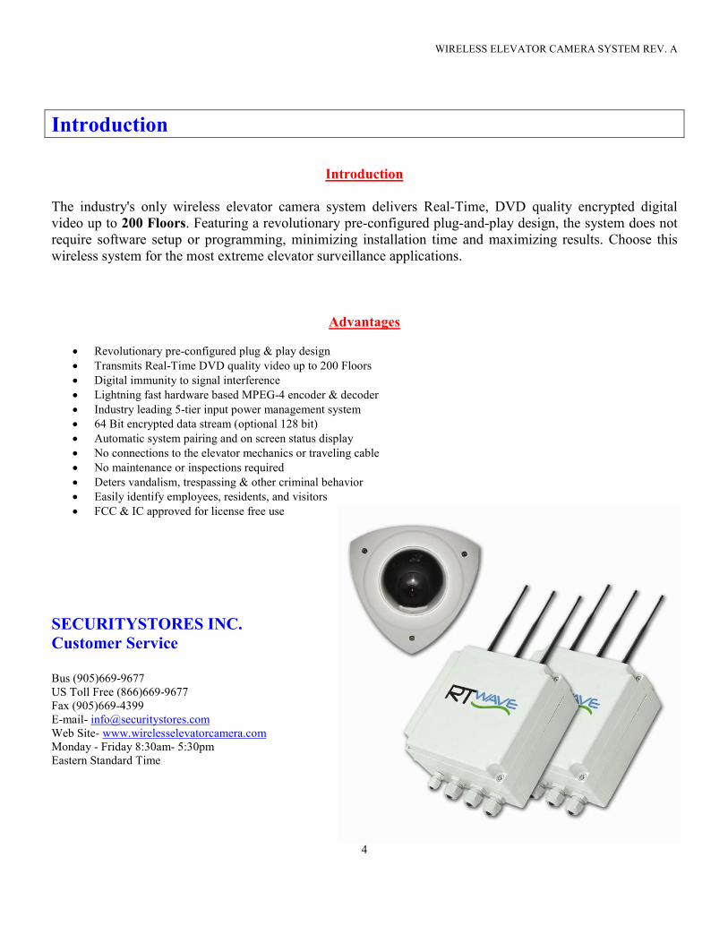
Introduction
The industry's only wireless elevator camera system delivers Real-Time, DVD quality encrypted digital
video up to 200 Floors. Featuring a revolutionary pre-configured plug-and-play design, the system does not
require software setup or programming, minimizing installation time and maximizing results. Choose this
wireless system for the most extreme elevator surveillance applications.
Advantages
• Revolutionary pre-configured plug & play design
• Transmits Real-Time DVD quality video up to 200 Floors
• Digital immunity to signal interference
• Lightning fast hardware based MPEG-4 encoder & decoder
• Industry leading 5-tier input power management system
• 64 Bit encrypted data stream (optional 128 bit)
• Automatic system pairing and on screen status display
• No connections to the elevator mechanics or traveling cable
• No maintenance or inspections required
• Deters vandalism, trespassing & other criminal behavior
• Easily identify employees, residents, and visitors
• FCC & IC approved for license free use
SECURITYSTORES INC.
Customer Service Bus (905)669-9677
US Toll Free (866)669-9677
Fax (905)669-4399
E-mail- [email protected]
Web Site- www.wirelesselevatorcamera.com
Monday - Friday 8:30am- 5:30pm
Eastern Standard Time
WIRELESS ELEVATOR CAMERA SYSTEM REV. A
5
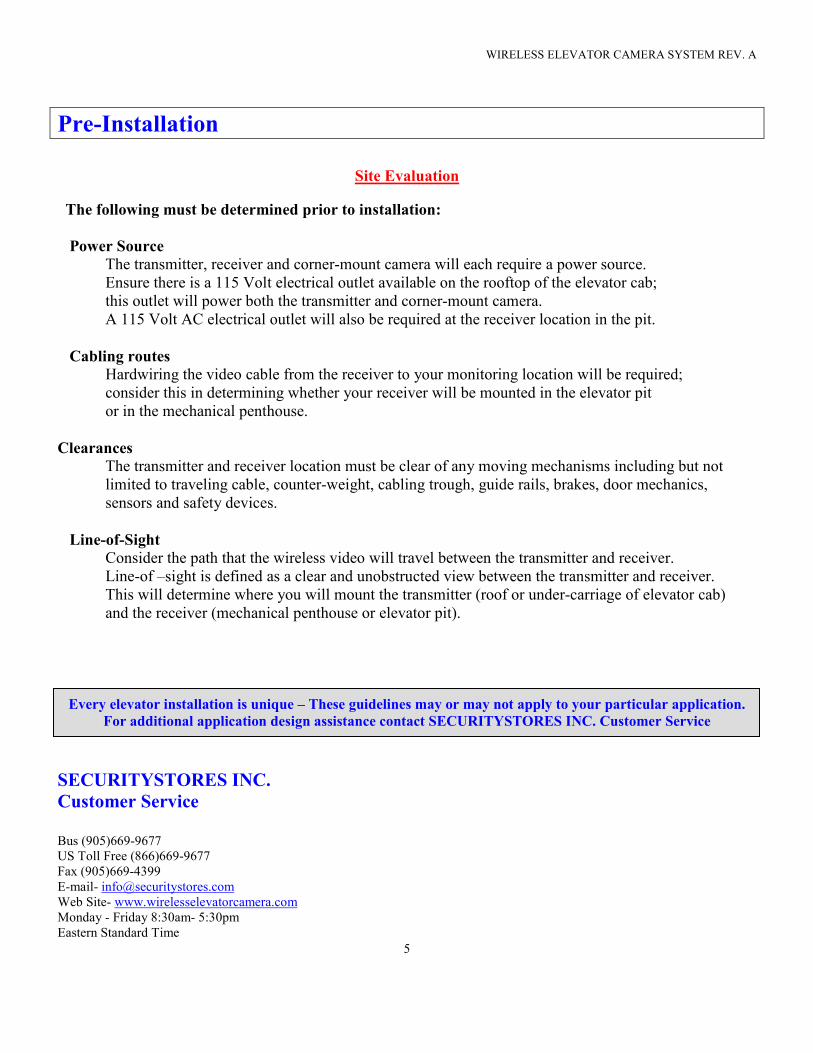
Pre-Installation
Site Evaluation
The following must be determined prior to installation:
Power Source
The transmitter, receiver and corner-mount camera will each require a power source.
Ensure there is a 115 Volt electrical outlet available on the rooftop of the elevator cab;
this outlet will power both the transmitter and corner-mount camera.
A 115 Volt AC electrical outlet will also be required at the receiver location in the pit.
Cabling routes
Hardwiring the video cable from the receiver to your monitoring location will be required;
consider this in determining whether your receiver will be mounted in the elevator pit
or in the mechanical penthouse.
Clearances
The transmitter and receiver location must be clear of any moving mechanisms including but not
limited to traveling cable, counter-weight, cabling trough, guide rails, brakes, door mechanics,
sensors and safety devices.
Line-of-Sight
Consider the path that the wireless video will travel between the transmitter and receiver.
Line-of –sight is defined as a clear and unobstructed view between the transmitter and receiver.
This will determine where you will mount the transmitter (roof or under-carriage of elevator cab)
and the receiver (mechanical penthouse or elevator pit).
Every elevator installation is unique – These guidelines may or may not apply to your particular application.
For additional application design assistance contact SECURITYSTORES INC. Customer Service
SECURITYSTORES INC.
Customer Service
Bus (905)669-9677
US Toll Free (866)669-9677
Fax (905)669-4399
E-mail- [email protected]
Web Site- www.wirelesselevatorcamera.com
Monday - Friday 8:30am- 5:30pm
Eastern Standard Time
WIRELESS ELEVATOR CAMERA SYSTEM REV. A
6
Tools Required
The Wireless Elevator Camera System is designed to be “Plug & Play”
and simple to install with minimal tools. The following is a list
of recommended tools to setup your system.
Drill - Used to create holes for the mounting bracket screws and the video cable,
which will be fed through the roof of the elevator cab.
Drill Bits - Standard drill bit set and ¾” hole saw (used for drilling hole through the roof of the cab)
Wire Stripper – For preparing power wires.
Philips Screw Driver – Used for unscrewing the front cover of the IP-67 enclosure to gain access to video,
audio and power terminations.
Micro-Phillips Screw Driver – Used for adjusting the focus on the camera lens
Metric 20mm Socket & Wrench (Closest Imperial Size – 13/16”) – Used to tighten or loosen the larger all
weather cable glands. Do not use pliers as they may cause damage to the cable glands
Metric 13mm Socket & Wrench (Closest Imperial Size – 5/8”) – Used for tightening or loosening the single
small all weather cable gland. Do not use pliers as they may cause damage to the cable glands
Hand Held LCD Monitor – Recommended for verifying video images at input to transmitter
and output from receiver. Perfect for camera angle and focus adjustment.
Multimeter – Measures voltage output, amperage, resistance and cable continuity.
Do Not Use Pliers - The pliers rigid grip may cause permanent damage to the cable glands
on the all weather IP-67 enclosure.
WIRELESS ELEVATOR CAMERA SYSTEM REV. A
7
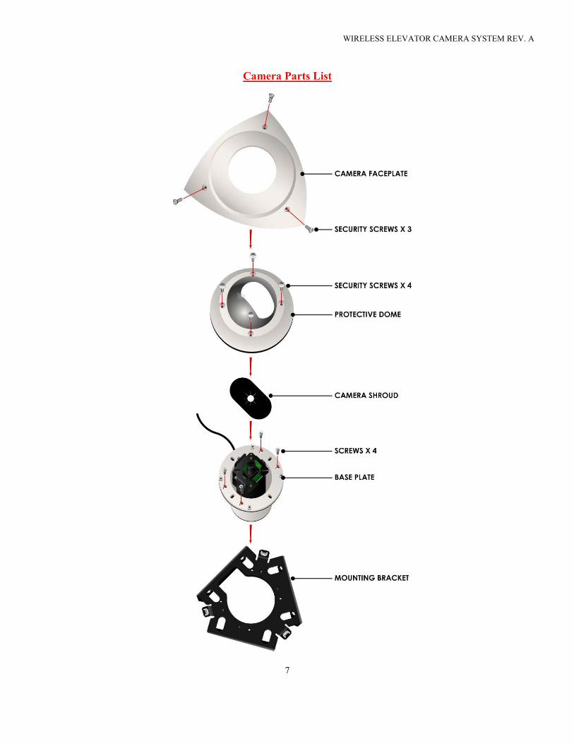
Camera Parts List
WIRELESS ELEVATOR CAMERA SYSTEM REV. A
8
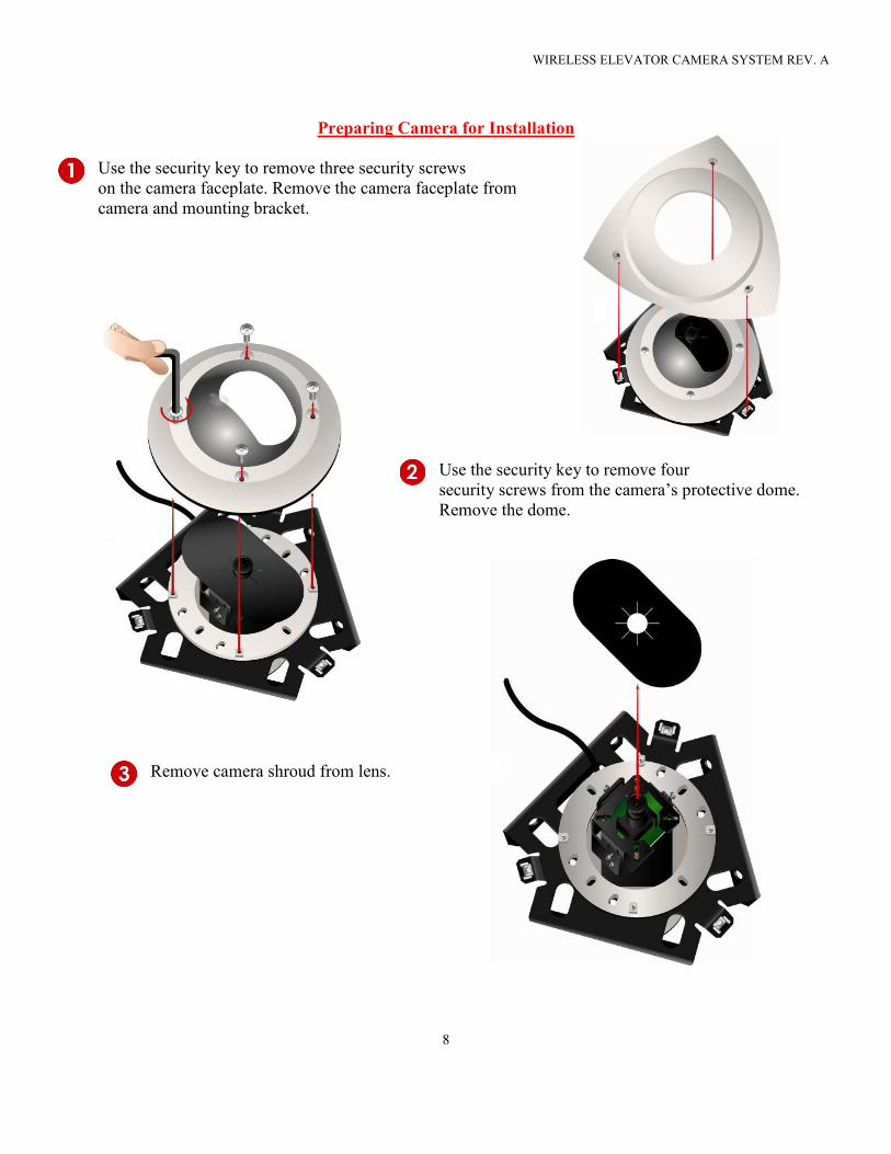
Preparing Camera for Installation
Use the security key to remove three security screws
on the camera faceplate. Remove the camera faceplate from
camera and mounting bracket.
Use the security key to remove four
security screws from the camera’s protective dome.
Remove the dome.
Remove camera shroud from lens.
WIRELESS ELEVATOR CAMERA SYSTEM REV. A
9
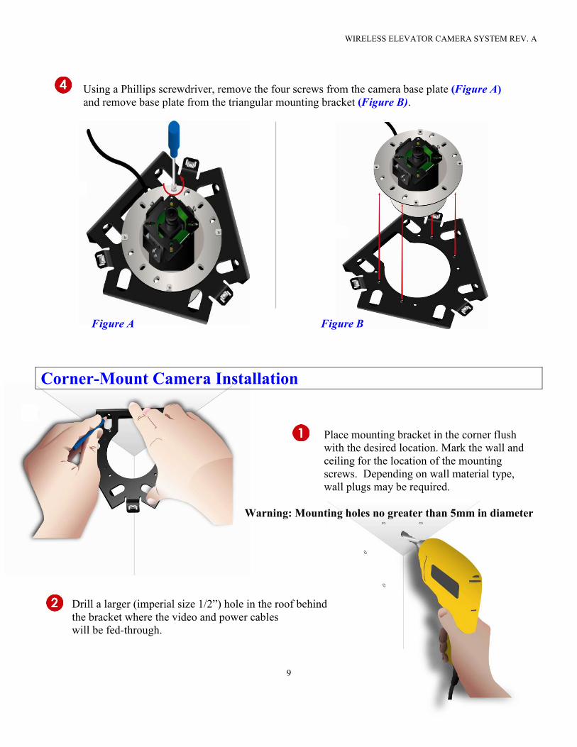
Using a Phillips screwdriver, remove the four screws from the camera base plate (Figure A)
and remove base plate from the triangular mounting bracket (Figure B).
Figure A Figure B
Corner-Mount Camera Installation
Place mounting bracket in the corner flush
with the desired location. Mark the wall and
ceiling for the location of the mounting
screws. Depending on wall material type,
wall plugs may be required.
Warning: Mounting holes no greater than 5mm in diameter
Drill a larger (imperial size 1/2”) hole in the roof behind
the bracket where the video and power cables
will be fed-through.
WIRELESS ELEVATOR CAMERA SYSTEM REV. A
10
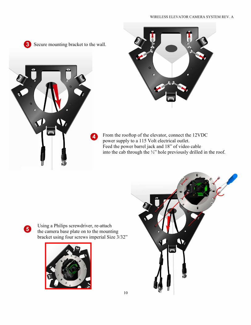
Secure mounting bracket to the wall.
From the rooftop of the elevator, connect the 12VDC
power supply to a 115 Volt electrical outlet.
Feed the power barrel jack and 18” of video cable
into the cab through the ½” hole previously drilled in the roof.
Using a Philips screwdriver, re-attach
the camera base plate on to the mounting
bracket using four screws imperial Size 3/32”
WIRELESS ELEVATOR CAMERA SYSTEM REV. A
11
Adjusting Camera Focus & Tilt
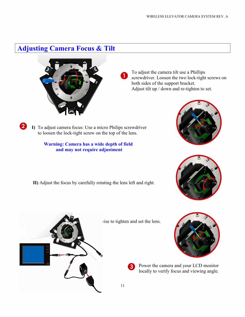
To adjust the camera tilt use a Phillips
screwdriver. Loosen the two lock-tight screws on
both sides of the support bracket.
Adjust tilt up / down and re-tighten to set.
I) To adjust camera focus: Use a micro Philips screwdriver
to loosen the lock-tight screw on the top of the lens.
Warning: Camera has a wide depth of field
and may not require adjustment
II) Adjust the focus by carefully rotating the lens left and right.
III) Turn the lock-tight screw clockwise to tighten and set the lens.
Power the camera and your LCD monitor
locally to verify focus and viewing angle.
WIRELESS ELEVATOR CAMERA SYSTEM REV. A
12
Securing Vandal-Proof Enclosure
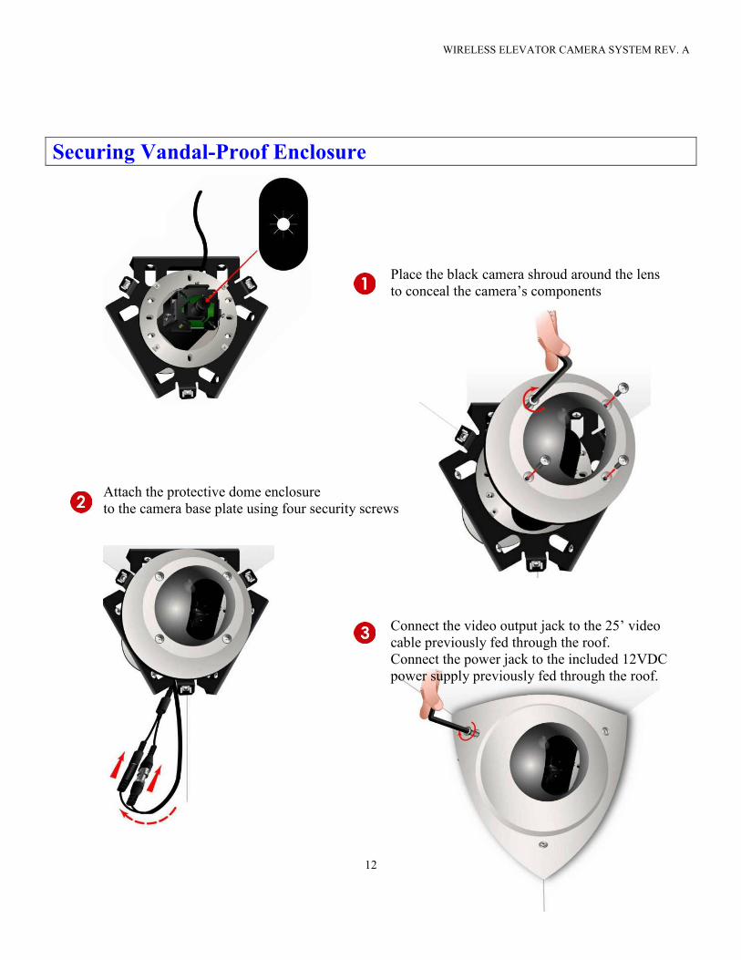
Place the black camera shroud around the lens
to conceal the camera’s components
Attach the protective dome enclosure
to the camera base plate using four security screws
Connect the video output jack to the 25’ video
cable previously fed through the roof.
Connect the power jack to the included 12VDC
power supply previously fed through the roof.
WIRELESS ELEVATOR CAMERA SYSTEM REV. A
13
Using the security key, attach the steel
faceplate to the mounting bracket.
Securing Power & Video Cable to Exterior Cab
Warning!!! The video cable must be clear of any moving mechanisms including but not limited to:
Traveling cable, counter-weight, cabling trough, guide rails, brakes, door mechanics, sensors and safety
devices. To ensure compliance with the safety standards and laws in your Country, State or City, consult
with your local Elevator authority for guidelines pertaining to properly securing cable
to the roof, exterior wall and cab platform prior to installation.
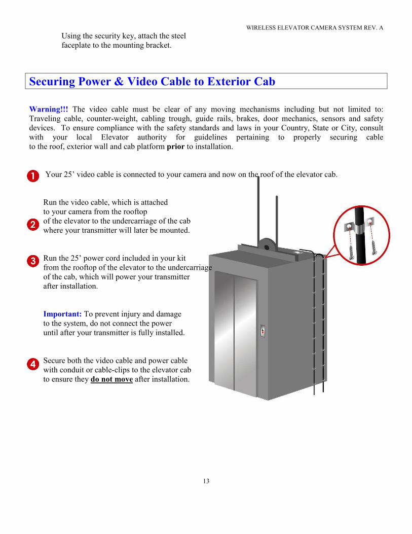
Your 25’ video cable is connected to your camera and now on the roof of the elevator cab.
Run the video cable, which is attached
to your camera from the rooftop
of the elevator to the undercarriage of the cab
where your transmitter will later be mounted.
Run the 25’ power cord included in your kit
from the rooftop of the elevator to the undercarriage
of the cab, which will power your transmitter
after installation.
Important: To prevent injury and damage
to the system, do not connect the power
until after your transmitter is fully installed.
Secure both the video cable and power cable
with conduit or cable-clips to the elevator cab
to ensure they do not move after installation.
WIRELESS ELEVATOR CAMERA SYSTEM REV. A
14
Opening & Closing the All Weather Enclosure
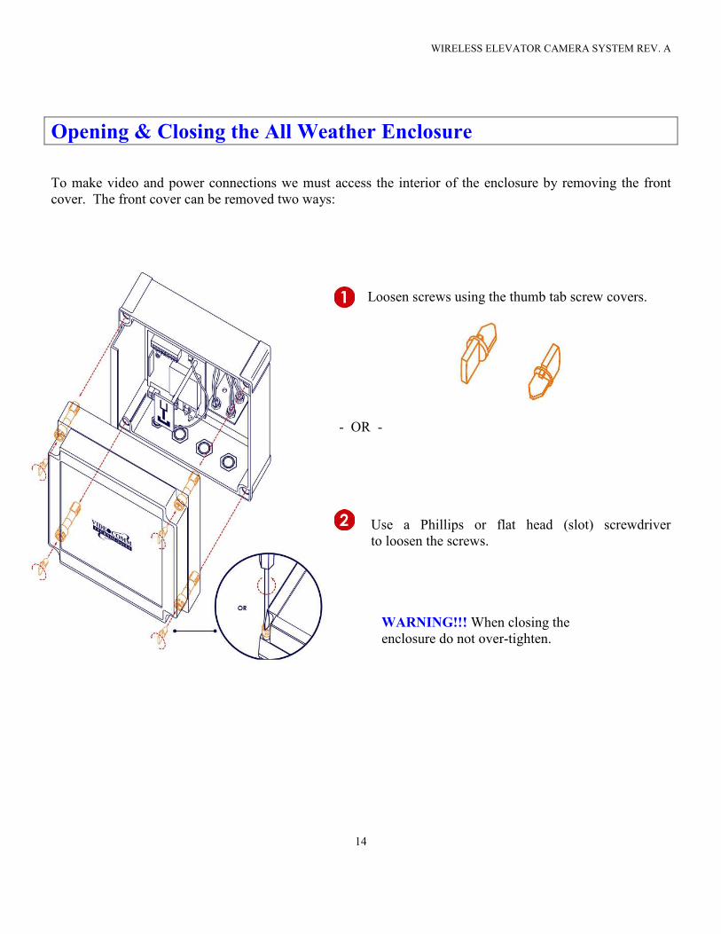
To make video and power connections we must access the interior of the enclosure by removing the front
cover. The front cover can be removed two ways:
Loosen screws using the thumb tab screw covers.
- OR -
Use a Phillips or flat head (slot) screwdriver
to loosen the screws.
WARNING!!! When closing the
enclosure do not over-tighten.
WIRELESS ELEVATOR CAMERA SYSTEM REV. A
15
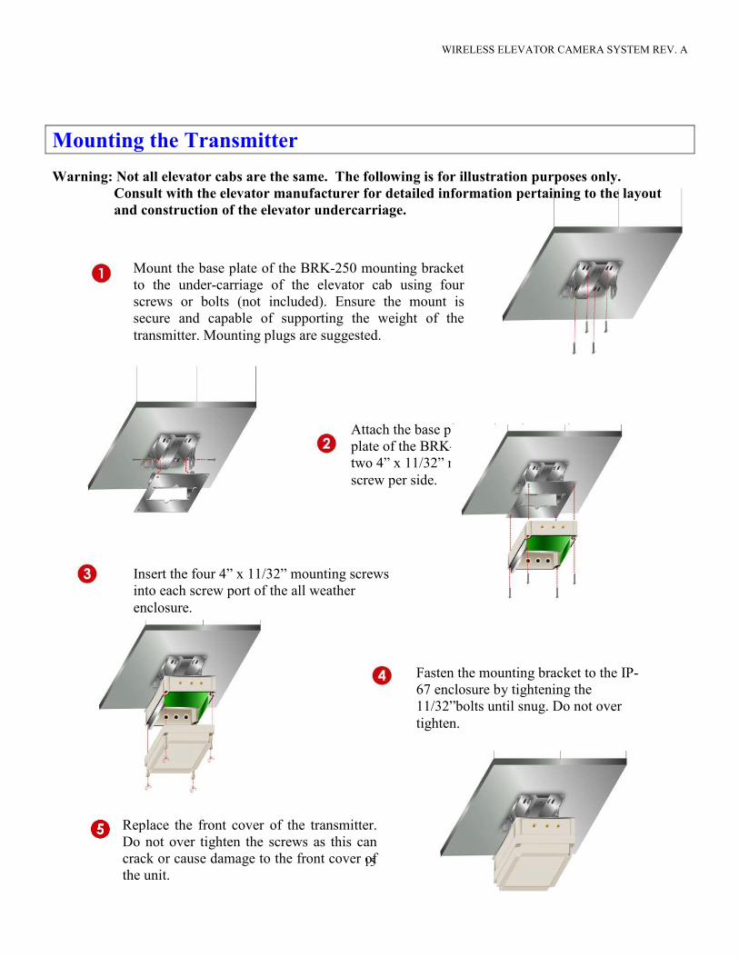
Attach the base plate and enclosure pivot
plate of the BRK-250 bracket using
two 4” x 11/32” mounting screws, one
screw per side.
Mounting the Transmitter
Warning: Not all elevator cabs are the same. The following is for illustration purposes only.
Consult with the elevator manufacturer for detailed information pertaining to the layout
and construction of the elevator undercarriage.
Mount the base plate of the BRK-250 mounting bracket
to the under-carriage of the elevator cab using four
screws or bolts (not included). Ensure the mount is
secure and capable of supporting the weight of the
transmitter. Mounting plugs are suggested.
Insert the four 4” x 11/32” mounting screws
into each screw port of the all weather
enclosure.
Fasten the mounting bracket to the IP-
67 enclosure by tightening the
11/32”bolts until snug. Do not over
tighten.
Replace the front cover of the transmitter.
Do not over tighten the screws as this can
crack or cause damage to the front cover of
the unit.
WIRELESS ELEVATOR CAMERA SYSTEM REV. A
16
Video Cable Connection to Transmitter
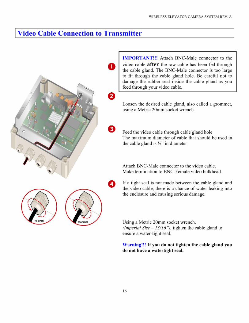
IMPORTANT!!! Attach BNC-Male connector to the
video cable after the raw cable has been fed through the cable gland. The BNC-Male connector is too large
to fit through the cable gland hole. Be careful not to
damage the rubber seal inside the cable gland as you
feed through your video cable.
Loosen the desired cable gland, also called a grommet,
using a Metric 20mm socket wrench.
Feed the video cable through cable gland hole
The maximum diameter of cable that should be used in
the cable gland is ½” in diameter
Attach BNC-Male connector to the video cable.
Make termination to BNC-Female video bulkhead
If a tight seal is not made between the cable gland and
the video cable, there is a chance of water leaking into
the enclosure and causing serious damage.
Using a Metric 20mm socket wrench.
(Imperial Size – 13/16”), tighten the cable gland to
ensure a water-tight seal.
Warning!!! If you do not tighten the cable gland you
do not have a watertight seal.
WIRELESS ELEVATOR CAMERA SYSTEM REV. A
17
Connecting the Omni-Directional Antennas
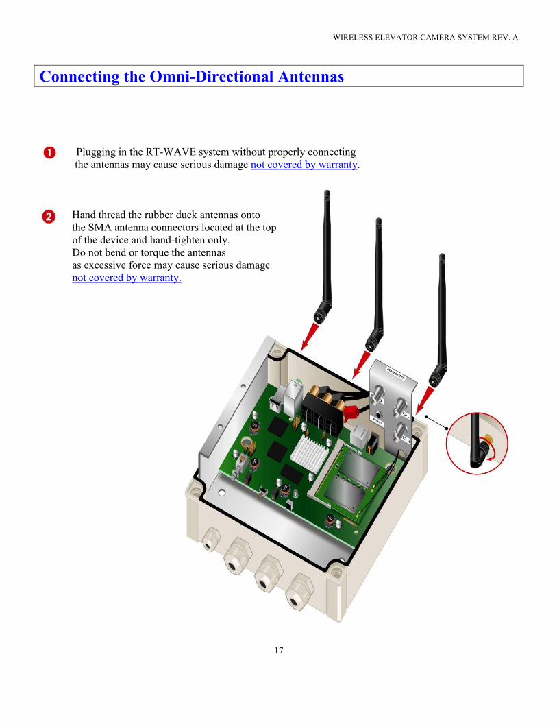
Plugging in the RT-WAVE system without properly connecting
the antennas may cause serious damage not covered by warranty.
Hand thread the rubber duck antennas onto
the SMA antenna connectors located at the top
of the device and hand-tighten only.
Do not bend or torque the antennas
as excessive force may cause serious damage
not covered by warranty.
WIRELESS ELEVATOR CAMERA SYSTEM REV. A
18
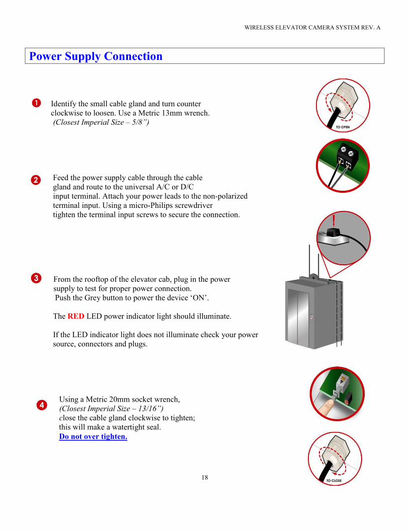
Power Supply Connection
Identify the small cable gland and turn counter
clockwise to loosen. Use a Metric 13mm wrench.
(Closest Imperial Size – 5/8”)
Feed the power supply cable through the cable
gland and route to the universal A/C or D/C
input terminal. Attach your power leads to the non-polarized
terminal input. Using a micro-Philips screwdriver
tighten the terminal input screws to secure the connection.
From the rooftop of the elevator cab, plug in the power
supply to test for proper power connection.
Push the Grey button to power the device ‘ON’.
The RED LED power indicator light should illuminate.
If the LED indicator light does not illuminate check your power
source, connectors and plugs.
Using a Metric 20mm socket wrench,
(Closest Imperial Size – 13/16”)
close the cable gland clockwise to tighten;
this will make a watertight seal.
Do not over tighten.
WIRELESS ELEVATOR CAMERA SYSTEM REV. A
19
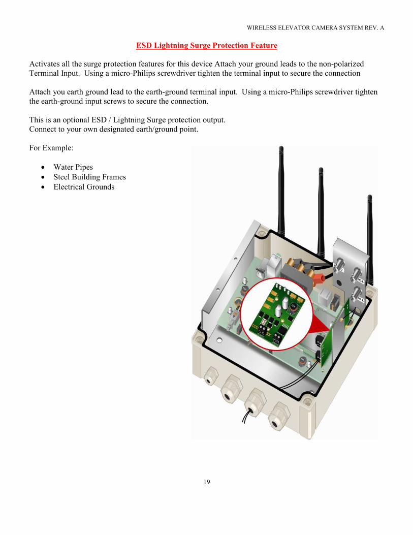
ESD Lightning Surge Protection Feature
Activates all the surge protection features for this device Attach your ground leads to the non-polarized
Terminal Input. Using a micro-Philips screwdriver tighten the terminal input to secure the connection
Attach you earth ground lead to the earth-ground terminal input. Using a micro-Philips screwdriver tighten
the earth-ground input screws to secure the connection.
This is an optional ESD / Lightning Surge protection output.
Connect to your own designated earth/ground point.
For Example:
• Water Pipes
• Steel Building Frames
• Electrical Grounds
WIRELESS ELEVATOR CAMERA SYSTEM REV. A
20
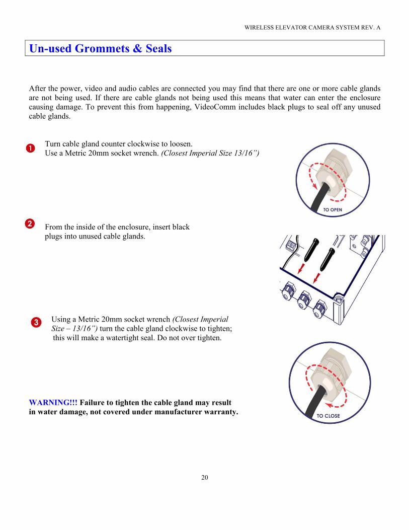
Un-used Grommets & Seals
After the power, video and audio cables are connected you may find that there are one or more cable glands
are not being used. If there are cable glands not being used this means that water can enter the enclosure
causing damage. To prevent this from happening, VideoComm includes black plugs to seal off any unused
cable glands.
Turn cable gland counter clockwise to loosen.
Use a Metric 20mm socket wrench. (Closest Imperial Size 13/16”)
From the inside of the enclosure, insert black
plugs into unused cable glands.
Using a Metric 20mm socket wrench (Closest Imperial
Size – 13/16”) turn the cable gland clockwise to tighten;
this will make a watertight seal. Do not over tighten.
WARNING!!! Failure to tighten the cable gland may result
in water damage, not covered under manufacturer warranty.
WIRELESS ELEVATOR CAMERA SYSTEM REV. A
21
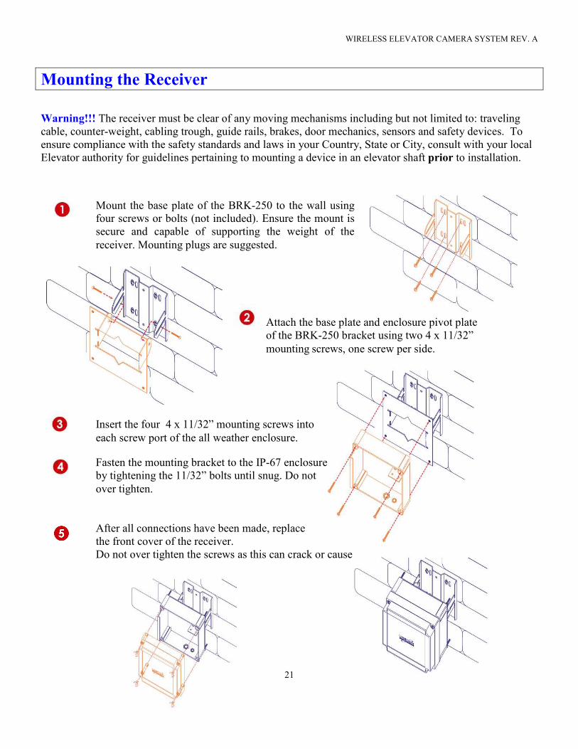
Attach the base plate and enclosure pivot plate
of the BRK-250 bracket using two 4 x 11/32”
mounting screws, one screw per side.
Mounting the Receiver
Warning!!! The receiver must be clear of any moving mechanisms including but not limited to: traveling
cable, counter-weight, cabling trough, guide rails, brakes, door mechanics, sensors and safety devices. To
ensure compliance with the safety standards and laws in your Country, State or City, consult with your local
Elevator authority for guidelines pertaining to mounting a device in an elevator shaft prior to installation.
Mount the base plate of the BRK-250 to the wall using
four screws or bolts (not included). Ensure the mount is
secure and capable of supporting the weight of the
receiver. Mounting plugs are suggested.
Insert the four 4 x 11/32” mounting screws into
each screw port of the all weather enclosure. Fasten the mounting bracket to the IP-67 enclosure
by tightening the 11/32” bolts until snug. Do not
over tighten.
After all connections have been made, replace
the front cover of the receiver.
Do not over tighten the screws as this can crack or cause
damage to the front cover of the unit.
WIRELESS ELEVATOR CAMERA SYSTEM REV. A
22
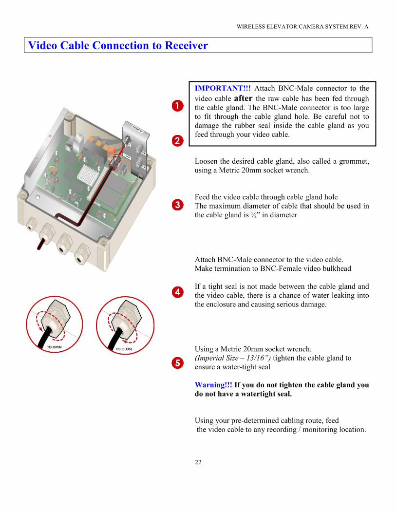
Video Cable Connection to Receiver
IMPORTANT!!! Attach BNC-Male connector to the
video cable after the raw cable has been fed through the cable gland. The BNC-Male connector is too large
to fit through the cable gland hole. Be careful not to
damage the rubber seal inside the cable gland as you
feed through your video cable.
Loosen the desired cable gland, also called a grommet,
using a Metric 20mm socket wrench.
Feed the video cable through cable gland hole
The maximum diameter of cable that should be used in
the cable gland is ½” in diameter
Attach BNC-Male connector to the video cable.
Make termination to BNC-Female video bulkhead
If a tight seal is not made between the cable gland and
the video cable, there is a chance of water leaking into
the enclosure and causing serious damage.
Using a Metric 20mm socket wrench.
(Imperial Size – 13/16”) tighten the cable gland to
ensure a water-tight seal
Warning!!! If you do not tighten the cable gland you
do not have a watertight seal.
Using your pre-determined cabling route, feed
the video cable to any recording / monitoring location.
WIRELESS ELEVATOR CAMERA SYSTEM REV. A
23
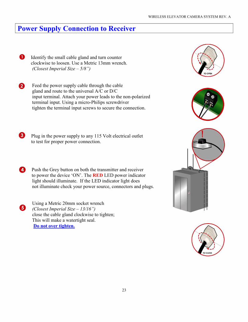
Power Supply Connection to Receiver
Identify the small cable gland and turn counter
clockwise to loosen. Use a Metric 13mm wrench.
(Closest Imperial Size – 5/8”)
Feed the power supply cable through the cable
gland and route to the universal A/C or D/C
input terminal. Attach your power leads to the non-polarized
terminal input. Using a micro-Philips screwdriver
tighten the terminal input screws to secure the connection.
Plug in the power supply to any 115 Volt electrical outlet
to test for proper power connection.
Push the Grey button on both the transmitter and receiver
to power the device ‘ON’. The RED LED power indicator
light should illuminate. If the LED indicator light does
not illuminate check your power source, connectors and plugs.
Using a Metric 20mm socket wrench
(Closest Imperial Size – 13/16”)
close the cable gland clockwise to tighten;
This will make a watertight seal.
Do not over tighten.
WIRELESS ELEVATOR CAMERA SYSTEM REV. A
24
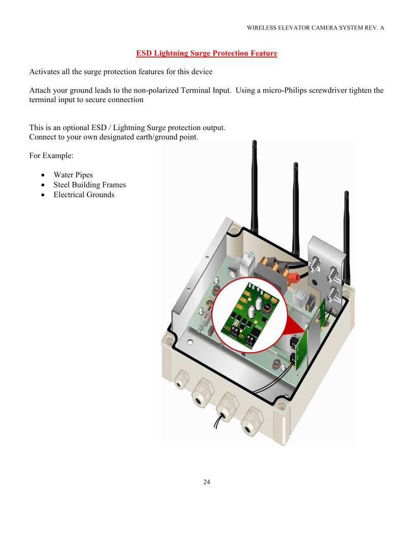
ESD Lightning Surge Protection Feature
Activates all the surge protection features for this device
Attach your ground leads to the non-polarized Terminal Input. Using a micro-Philips screwdriver tighten the
terminal input to secure connection
This is an optional ESD / Lightning Surge protection output.
Connect to your own designated earth/ground point.
For Example:
• Water Pipes
• Steel Building Frames
• Electrical Grounds
WIRELESS ELEVATOR CAMERA SYSTEM REV. A
25
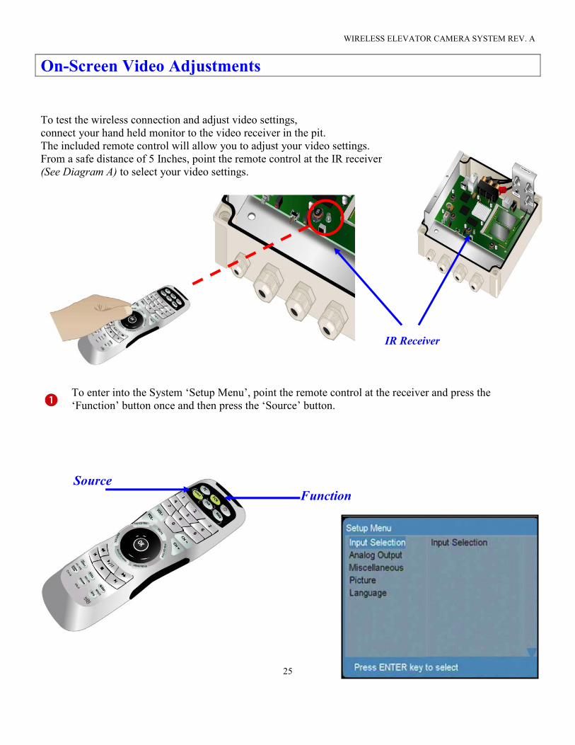
On-Screen Video Adjustments
To test the wireless connection and adjust video settings,
connect your hand held monitor to the video receiver in the pit.
The included remote control will allow you to adjust your video settings.
From a safe distance of 5 Inches, point the remote control at the IR receiver
(See Diagram A) to select your video settings.
IR Receiver
To enter into the System ‘Setup Menu’, point the remote control at the receiver and press the
‘Function’ button once and then press the ‘Source’ button.
Source
Function
WIRELESS ELEVATOR CAMERA SYSTEM REV. A
26
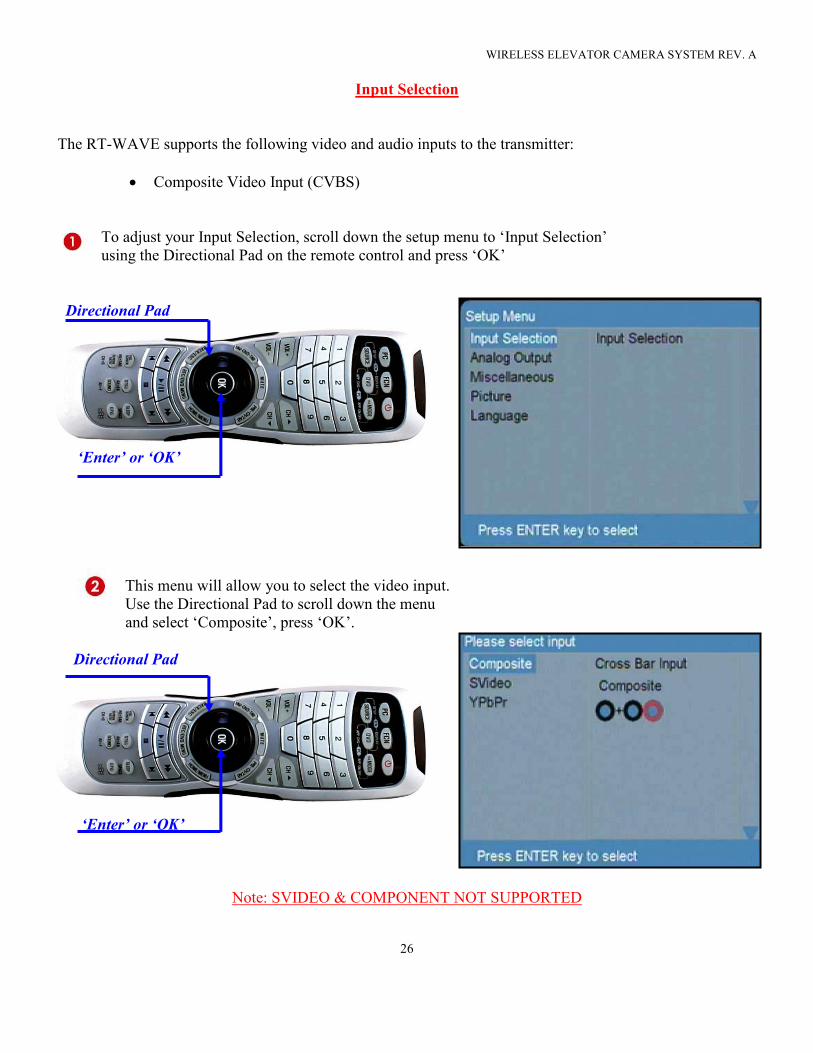
Input Selection
The RT-WAVE supports the following video and audio inputs to the transmitter:
• Composite Video Input (CVBS)
To adjust your Input Selection, scroll down the setup menu to ‘Input Selection’
using the Directional Pad on the remote control and press ‘OK’
Directional Pad
‘Enter’ or ‘OK’
This menu will allow you to select the video input.
Use the Directional Pad to scroll down the menu
and select ‘Composite’, press ‘OK’.
Directional Pad
‘Enter’ or ‘OK’
Note: SVIDEO & COMPONENT NOT SUPPORTED
WIRELESS ELEVATOR CAMERA SYSTEM REV. A
27
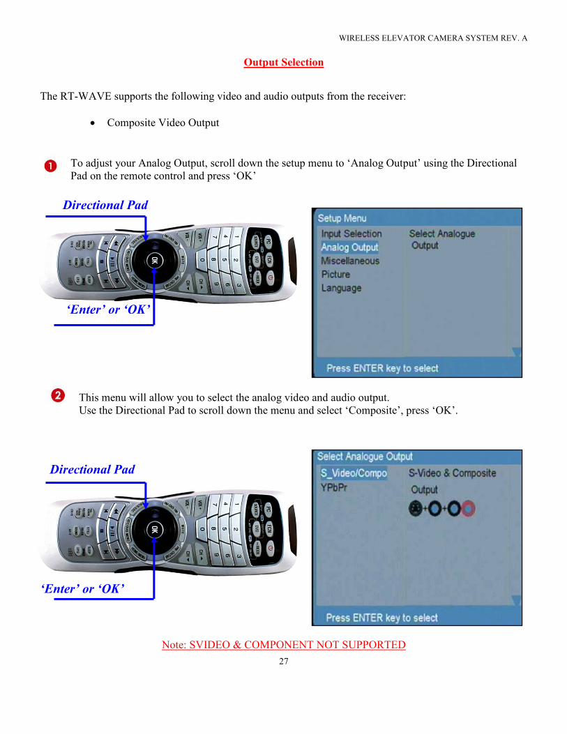
Output Selection
The RT-WAVE supports the following video and audio outputs from the receiver:
• Composite Video Output
To adjust your Analog Output, scroll down the setup menu to ‘Analog Output’ using the Directional
Pad on the remote control and press ‘OK’
Directional Pad
‘Enter’ or ‘OK’
This menu will allow you to select the analog video and audio output.
Use the Directional Pad to scroll down the menu and select ‘Composite’, press ‘OK’.
Directional Pad
‘Enter’ or ‘OK’
Note: SVIDEO & COMPONENT NOT SUPPORTED
WIRELESS ELEVATOR CAMERA SYSTEM REV. A
28
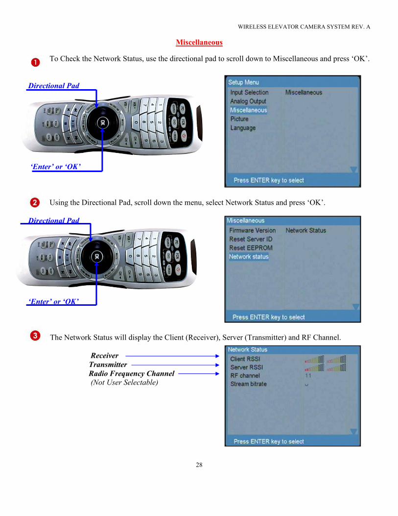
Miscellaneous
To Check the Network Status, use the directional pad to scroll down to Miscellaneous and press ‘OK’.
Directional Pad
‘Enter’ or ‘OK’
Using the Directional Pad, scroll down the menu, select Network Status and press ‘OK’.
Directional Pad
‘Enter’ or ‘OK’
The Network Status will display the Client (Receiver), Server (Transmitter) and RF Channel.
Receiver
Transmitter
Radio Frequency Channel
(Not User Selectable)
WIRELESS ELEVATOR CAMERA SYSTEM REV. A
29
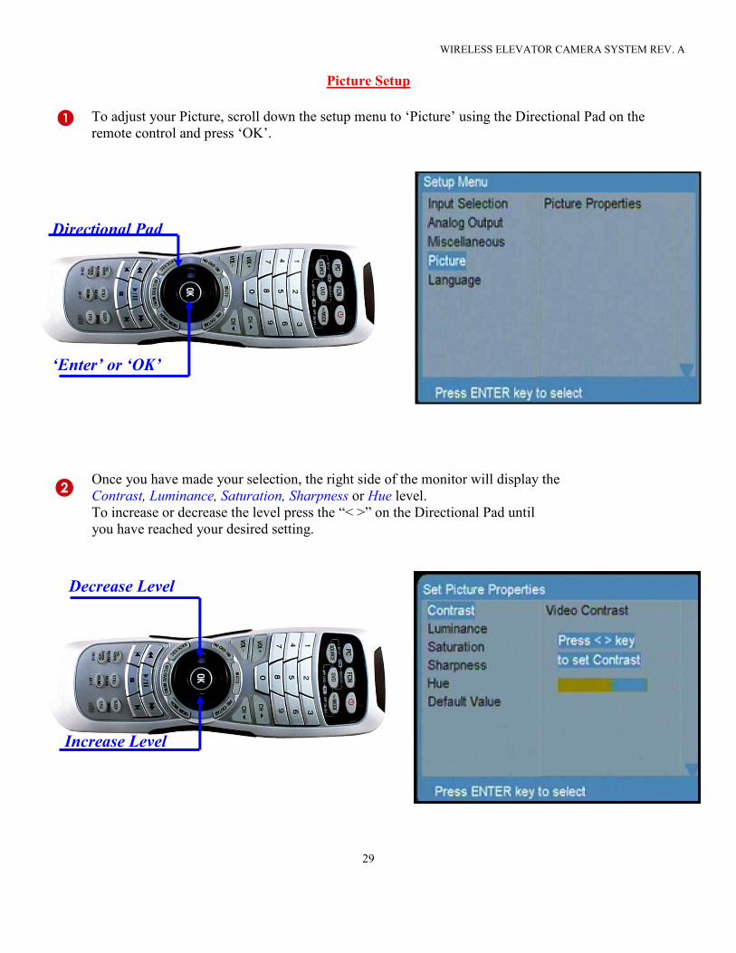
Picture Setup
To adjust your Picture, scroll down the setup menu to ‘Picture’ using the Directional Pad on the
remote control and press ‘OK’.
Directional Pad
‘Enter’ or ‘OK’
Once you have made your selection, the right side of the monitor will display the
Contrast, Luminance, Saturation, Sharpness or Hue level.
To increase or decrease the level press the “< >” on the Directional Pad until
you have reached your desired setting.
Decrease Level
Increase Level

WIRELESS ELEVATOR CAMERA SYSTEM REV. A
30
This page is intentionally left blank