Embed Size (px)
Citation preview
ITR/2-2
- 1 -
Review of the ITER Fuel Cycle
D. Babineau1, S. Maruyama
1, R. Pearce
1, M. Glugla
1, Li Bo
2, B. Rogers
3, S. Willms
4,
G. Piazza5, T. Yamanishi
6, S. H. Yun
7, L. Worth
1 and W. Shu
1
E-mail: [email protected] 1ITER Organization Bldg 525A, Route de Vinon sur Verdon, 13115 Cadarache, France
2Southwest Institute of Physics, Chengdu, China
3Savannah River National Laboratory, Aiken, SC USA
4Los Alamos National Laboratory, Los Alamos, NM, USA
5Fusion for Energy, Barcelona, Spain
6JAEA, Directorates of Fusion Energy Research, Shirakata-Shirane, Tokai, Ibaraki, Japan
7National Fusion Research Institute, Daejeon, Korea
Abstract. ITER is a fusion tokamak, being fully designed for deuterium/tritium operation. The ITER Fuel Cycle
consists of three major sections which are Vacuum, the Tritium Plant and Fuelling and Wall Conditioning. In
general the Fuel Cycle supplies the fuel particles and impurities into the tokamak for stable plasma operation
and processes all the exhaust gases from the Torus. The ITER Fuel Cycle must be capable of delivering,
exhausting and purifying fuel particles (H2, D2 and DT) at rates that are orders of magnitude higher than have
been done previously in industrial applications with fluids containing tritium. The plasma will be fuelled in the
forms of hydrogenic ice pellet injection and gas puffing. The Fuelling system also provides hydrogen and
deuterium to the diagnostics and heating Neutral Beam injectors respectively. The ITER vacuum pumping
systems are used for initial evacuation, continuous maintenance of the required conditions in the torus, plasma
density control and neutral particle exhaust. The Tritium Plant supplies deuterium and tritium from external
sources and treats all tritiated fluids from ITER operation through Tokamak Exhaust Processing, Isotope
Separation and Storage and Delivery Systems to remove and recover deuterium and tritium for refuelling. The
Fuel Cycle also provides tritium confinement systems for the Tokamak Complex and the Hot Cell Facility.
Confinement of tritium is achieved through multiple passive barriers and the use of active systems such as the
Detritiation systems. Another challenging aspect for the Fuel Cycle is tritium accountancy and tracking. To
satisfy safety criteria it will be necessary to track and trend the inventory within the vacuum vessel and other
major Fuel Cycle systems. In order to perform this inventory measurement, tritium must be moved to hydride
storage beds and measured. The ITER research plan encompasses four operational phases: hydrogen (protium),
hydrogen / helium, deuterium / trace tritium and full deuterium/tritium operations. The Fuel Cycle systems are
not all required to be available at the beginning; however each of the operational phases requires an increasing
number of the systems to be available with increasing duties as time progresses in each phase. An initial
coherent strategy to commission each of these systems as they are needed has been developed.
1. Introduction
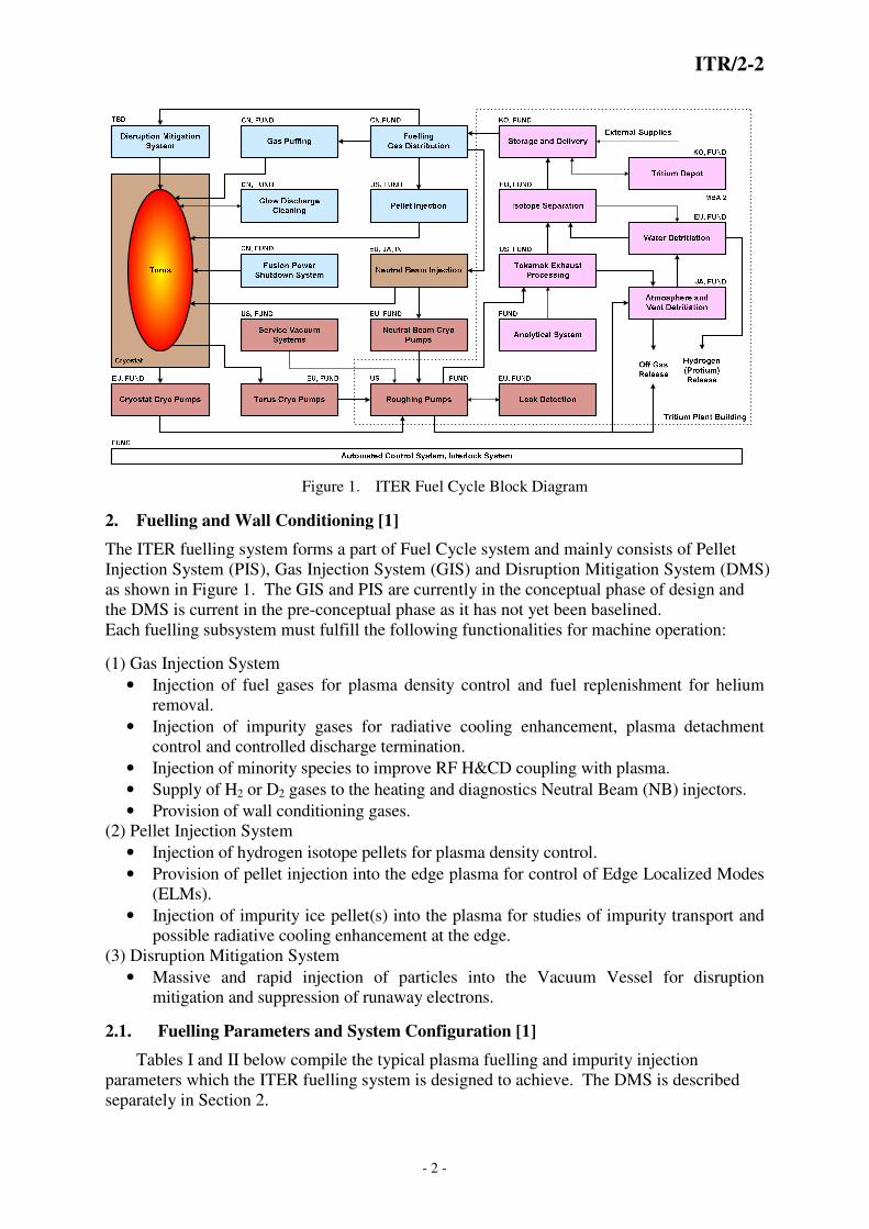
The ITER Fuel Cycle consists of three major systems; Vacuum, Tritium Plant and Fuelling. .
It can be further divided into 19 sub-systems as outlined in Figure 1. The Fuel Cycle supplies
the fuel particles and into the tokamak for stable plasma operation and processes all the
exhaust gases from the Torus. It must be capable of delivering, exhausting and purifying fuel
particles (H2, D2 and DT) at an average rate of 200 Pa·m3s
-1 and peak of 400 Pa·m
3s
-1 , as
well as supply inert gas s such Ne, Ar and N2 with rates up to 100 Pa·m3s
-1 for radiating heat
from the plasma. Such flows are orders of magnitude higher than have been done previously
with tritium processes. This paper describes the major interfaces between these systems, the
overall design status, schedule strategy and challenges associated with design of the ITER
Fuel Cycle systems.
ITR/2-2
- 2 -
Figure 1. ITER Fuel Cycle Block Diagram
2. Fuelling and Wall Conditioning [1]
The ITER fuelling system forms a part of Fuel Cycle system and mainly consists of Pellet
Injection System (PIS), Gas Injection System (GIS) and Disruption Mitigation System (DMS)
as shown in Figure 1. The GIS and PIS are currently in the conceptual phase of design and
the DMS is current in the pre-conceptual phase as it has not yet been baselined.
Each fuelling subsystem must fulfill the following functionalities for machine operation:
(1) Gas Injection System
• Injection of fuel gases for plasma density control and fuel replenishment for helium
removal.
• Injection of impurity gases for radiative cooling enhancement, plasma detachment
control and controlled discharge termination.
• Injection of minority species to improve RF H&CD coupling with plasma.
• Supply of H2 or D2 gases to the heating and diagnostics Neutral Beam (NB) injectors.
• Provision of wall conditioning gases.
(2) Pellet Injection System
• Injection of hydrogen isotope pellets for plasma density control.
• Provision of pellet injection into the edge plasma for control of Edge Localized Modes
(ELMs).
• Injection of impurity ice pellet(s) into the plasma for studies of impurity transport and
possible radiative cooling enhancement at the edge.
(3) Disruption Mitigation System
• Massive and rapid injection of particles into the Vacuum Vessel for disruption
mitigation and suppression of runaway electrons.
2.1. Fuelling Parameters and System Configuration [1]
Tables I and II below compile the typical plasma fuelling and impurity injection
parameters which the ITER fuelling system is designed to achieve. The DMS is described
separately in Section 2.

TABLE I - PLASMA FUELLING PARAM
Parameters Unit
Fuelling gas
Average/Peak fuelling rate for H2, D2,
DT for gas puffing Pa
Average/Peak fuelling rate for Tritium1)
for pellet injection Pa
Average/Peak fuelling rate for other
hydrogen species for pellet injection Pa
Average/Peak fuelling rate for 3He or 4He
Pa
Duration at peak fuelling rate s
GIS response time to 63% at 20 Pa
m3/s s
1) 90% tritium + 10% deuterium.
The ITER fuelling system has the following configuration and is distributed around tokamak
(Figure 2).
(1) Gas Injection System
• Upper port level: 4 gas valve boxes (GVB) to provide uniform toroidal distribution.
• Divertor port level: 6 GVBs at every
• Dedicated manifold for fuel supply to the heating and diagnostic NB injectors.
(2) Pellet Injection System
• Three divertor ports, same as those for GIS, are allocated. (Each port
one PIS cask which can accommodate 2 injectors.)
• Two injectors will be installed for the beginning of machine operations.
• Six injectors will be available
(3) Disruption Mitigation System
• Two locations at upper port level a
Figure 2.
2.2. Disruption Mitigation System [
Mitigation of thermal and electromagnetic (EM) loads due to major disruptions, vertical
displacement events (VDE) and runaway electrons (RE) is
protection in ITER. During the machine lifetime, these events are expected to occur roughly
3000, 3000 and 300 times respectively for disrup
having the potential to cause serious damage to p
circuits, etc, it is critical that ITER be equipped with a sufficiently reliable mitigation system.
This system must also ensure that its use does not lead to long periods of machine down time
(to evacuate the particles which must be injecte
- 3 -
LASMA FUELLING PARAMETERS TABLE II - IMPURITY GAS
INJECTION FOR RADIAT
Unit 3He, 4He
H2, D2,
DT, T2
Pa·m3/s 200/400
Pa·m3/s 111/111
Pa·m3/s 100/100
Pa·m3/s 60/
120
< 10
< 1
ITER fuelling system has the following configuration and is distributed around tokamak
Upper port level: 4 gas valve boxes (GVB) to provide uniform toroidal distribution.
GVBs at every 60° in toroidal direction.
for fuel supply to the heating and diagnostic NB injectors.
Three divertor ports, same as those for GIS, are allocated. (Each port
PIS cask which can accommodate 2 injectors.)
Two injectors will be installed for the beginning of machine operations.
Six injectors will be available at the start of DT plasma operation.
(3) Disruption Mitigation System
Two locations at upper port level are presently allocated.
Figure 2. Toroidal distribution of tokamak fuelling
Disruption Mitigation System [1,5]
Mitigation of thermal and electromagnetic (EM) loads due to major disruptions, vertical
displacement events (VDE) and runaway electrons (RE) is indispensable for machine
protection in ITER. During the machine lifetime, these events are expected to occur roughly
3000, 3000 and 300 times respectively for disruptions, RE generation and VDEs.
having the potential to cause serious damage to plasma-facing components, water cooling
circuits, etc, it is critical that ITER be equipped with a sufficiently reliable mitigation system.
This system must also ensure that its use does not lead to long periods of machine down time
les which must be injected to mitigate the disruption).
Parameters
Impurity gases
Maximum number of impurity gases to
be injected simultaneously
Average/Peak injection rate for each gas
Average/Peak simultaneous injection rate
all gases
Duration at peak fuelling rate
Response time to 63% at 5 Pa m
ITR/2-2
MPURITY GAS
INJECTION FOR RADIATIVE COOLING
ITER fuelling system has the following configuration and is distributed around tokamak
Upper port level: 4 gas valve boxes (GVB) to provide uniform toroidal distribution.
for fuel supply to the heating and diagnostic NB injectors.
Three divertor ports, same as those for GIS, are allocated. (Each port is equipped with
Two injectors will be installed for the beginning of machine operations.
Toroidal distribution of tokamak fuelling
Mitigation of thermal and electromagnetic (EM) loads due to major disruptions, vertical
indispensable for machine
protection in ITER. During the machine lifetime, these events are expected to occur roughly
tions, RE generation and VDEs. With each
facing components, water cooling
circuits, etc, it is critical that ITER be equipped with a sufficiently reliable mitigation system.
This system must also ensure that its use does not lead to long periods of machine down time
d to mitigate the disruption). A reasonable
Unit Value
N2, Ar,
Ne
Maximum number of impurity gases to 2
Average/Peak injection rate for each gas Pa·m3/s 10/100
Average/Peak simultaneous injection rate Pa·m3/s 10/100
Duration at peak fuelling rate s < 10
Response time to 63% at 5 Pa m3/s s < 1

ITR/2-2
- 4 -
recovery time of ~3 hours is currently specified. Physics studies are currently underway to
define the DMS requirements and are being conducted in parallel with an engineering
assessment of candidate systems. Table III compares 3 possible candidate systems – Massive
Pellet Injection (MPI), Massive Gas Injection (MGI) and Massive Beryllium Injection (MBI)
– from the engineering standpoint. Important elements to judge the feasibility of the system
are: (1) environmental condition of the possible location of DMS installation, (2) gas load to
vacuum system and tritium plant, (3) heat load to cryoplant, (4) repeatability and
reproducibility of mitigation operation, and (5) safety concerns. Requirements on DMS,
specifically impurity species and their quantities, have significant impacts on the Vacuum
and Tokamak Exhaust Systems. Considering uncertainties in roughing pump design, and
avoiding any impact on TEP design and operation, it is advised to avoid a prompt
regeneration of torus cryopumps. This allows regulating the off-gas flow to the TEP. The
following gas species and quantities seem not to require prompt cryopump regeneration: Ne -
40 kPa m3; He - 40 ~ 50 kPa m
3 ; D2 - 30 kPa m
3 (additional 20~30 kPa m
3 of Ne as mixture)
TABLE III - Comparison of advantage (+) and Disadvantage (–) of candidate DMS
Priority DMS Species & Quantity Comments
1 Massive pellet injection (MPI)
Neon (40 kPa·m3)
+ Less gas load to VS and TP due to high assimilation � Short recovery time and less heat load to cryoplant
+ Moderate environment in port cell for dedicated pellet injector + Easy to refill the gas + Easy to maintain (hands-on maintenance in port cell) – Not applicable for He
2 Massive gas injection (MGI)
Helium (500 kPa·m3) or Neon (100 kPa·m3)
+ Easy to refill the gas – Severe environmental condition in port plug (neutron and gamma
irradiation, high magnetic field and high temperature) for dedicated MGI valves
– Remote handling maintenance together with port plug – Higher gas load to VS and TP � Long recovery time and higher heat
load to cryoplant
3 Massive beryllium injection
Beryllium (400 g)
+ No impact on VS and TP + Moderate environment in port cell dedicated for Be injector + Easy to maintain (hands on maintenance in port cell) – Beryllium dust issue – Tritium inventory and recovery issue – Refill of beryllium for repetitive injection
3. Vacuum System [2,3]
The ITER Vacuum System consists of a number of large or distributed vacuums
including the torus vacuum, neutral injection vacuums, cryostat vacuum, cryogenic guard
vacuum system, transmission line vacuums, and diagnostic vacuums. These are served by
custom cryopumps ( Torus (TCP), Neutral Beam (NCP), Cryostat (CCP)), and a mixture of
standard and custom pumps in the Roughing Pump System (RPS), diagnostic, transmission
line and Service Vacuum System (SVS). . In plasma operations the torus cryopumps operate
in a fast regenerative mode cyclically pumping the tokamak and releasing the exhaust gas to
the roughing system. In addition to the proven techniques for plasma density control it will be
possible to control the neutral particle exhaust on ITER by varying the opening of the TCP’s.
All pumping systems apart from the cryogenic guard vacuum system discharge via the RPS
to the Tritium Plant systems. Each of the vacuum systems fulfils the following functionalities
to support machine operation:
(1) Torus Cryopumps
• Evacuation of the torus from the crossover pressure to the pre-bake base pressures.
• Pump-out of gases released from vacuum facing surfaces during baking and
conditioning.
• Intra-pulse pumping to remove excess of fuelling gas, impurities and helium.

ITR/2-2
- 5 -
• Pumping between pulses to attain a low enough pressure for pre-fill and breakdown.
• Leak detection of Vacuum Vessel.
(2) Cryostat Cryopumps - Identical design to Torus Cryopumps.
• Evacuation of the cryostat to high vacuum prior to the cool-down of the magnet.
• Pumping of helium leaks
• Pumping of protium from outgassing metallic surfaces and gasses generated by
irradiation of exposed epoxy (e.g. protium and alkanes).
• Leak detection of the Cryostat.
(3) Neutral Beam Cryopumps
• Evacuation of the Neutral Beams vessel from the crossover pressure to operation
requirement base pressure.
• Pumping of excess gas and impurities during dwell time.
• Ensure the gas density distribution and the gas flow necessary for effective beamline
operation.
• Pumping the gas that is fed into the ion source and the neutraliser for production of
the ion beam.
• Controlling the pressure to minimise stripping losses.
(4) Roughing Pump System
• Roughing of the torus, Cryostat, NB, Service Vacuum System (SVS), diagnostics,
transmission lines, from atmosphere,
• Evacuation of released gases from the torus, NB, and cryostat cryopumps during
partial and total regeneration and from the Service Vacuum System (SVS) and
Diagnostics.
• Sequential pumping/purging to dehydrate the cryostat internals prior to magnet cool-
down
• Pumping of Torus, NB, Service Vacuum System or cryostat during leak testing
• Pumping of potentially wet volumes, to assist with drying following incident or air
venting.
(5) Service Vacuum System is designed to provide vacuum service to more than 1500 clients:
• Interspaces of vulnerable components with double containment (double bellows,
double seals interspaces)
• Systems requiring vacuum to operate (diagnostics, waveguides)
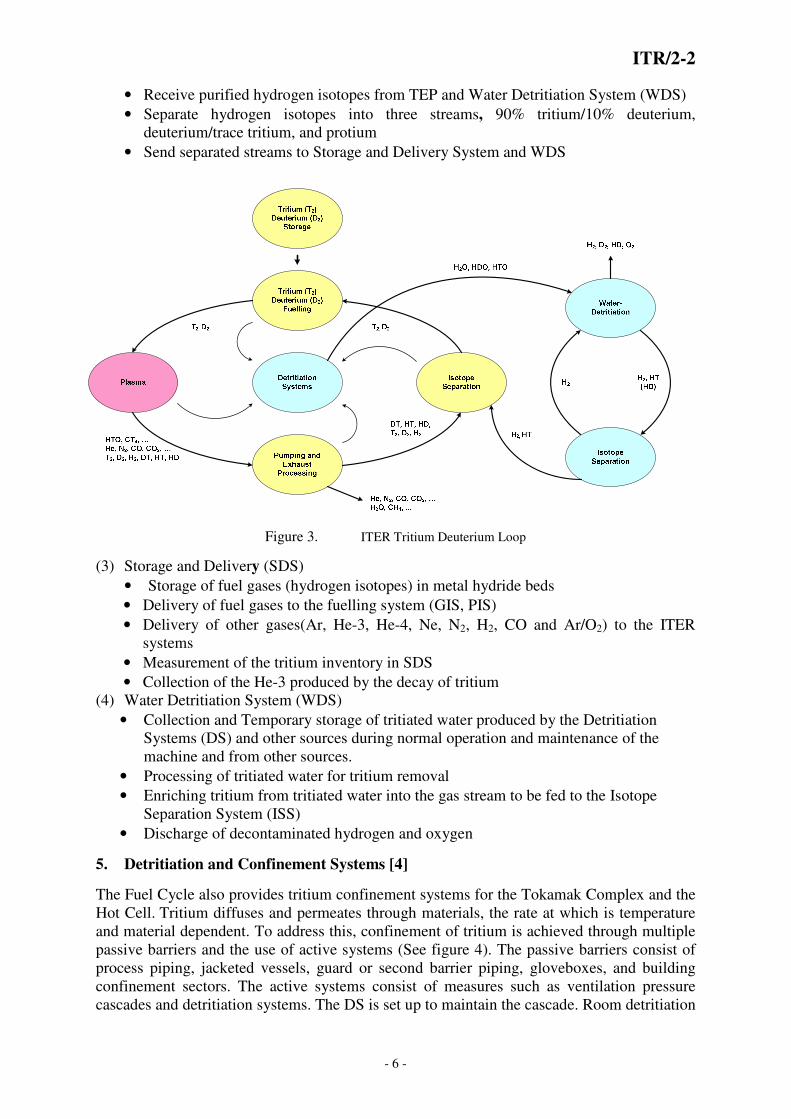
4. Tritium Plant Systems [4]
The Tritium Plant supplies deuterium and tritium from external sources and treats all tritiated
fluids from ITER operation through Tokamak Exhaust Processing, Isotope Separation and
Storage and Delivery Systems to remove and recover deuterium and tritium for refuelling.
See Figure 3 for graphic depiction of Fuel Cycle and Tritium Plant systems interaction. Each
of the Tritium Plant systems fulfils the following functionalities to support machine
operation:
(1) Tokamak Exhaust Processing (TEP)
• Receive exhaust gases from Roughing Pump System
• Purify hydrogen isotopes through a combination of catalytic conversion of tritiated
hydrocarbon compounds and permeation membranes
• Send detritiated (< 7.4 x 10⁻⁸
Bq/day) byproduct gases to Detritiation Systems for
further processing
• Send purified hydrogen isotopes to Isotope Separation for further processing
(2) Isotope Separation (ISS)
ITR/2-2
- 6 -
• Receive purified hydrogen isotopes from TEP and Water Detritiation System (WDS)
• Separate hydrogen isotopes into three streams, 90% tritium/10% deuterium,
deuterium/trace tritium, and protium
• Send separated streams to Storage and Delivery System and WDS
Figure 3. ITER Tritium Deuterium Loop
(3) Storage and Delivery (SDS)
• Storage of fuel gases (hydrogen isotopes) in metal hydride beds
• Delivery of fuel gases to the fuelling system (GIS, PIS)
• Delivery of other gases(Ar, He-3, He-4, Ne, N2, H2, CO and Ar/O2) to the ITER
systems
• Measurement of the tritium inventory in SDS
• Collection of the He-3 produced by the decay of tritium
(4) Water Detritiation System (WDS)
• Collection and Temporary storage of tritiated water produced by the Detritiation
Systems (DS) and other sources during normal operation and maintenance of the
machine and from other sources.
• Processing of tritiated water for tritium removal
• Enriching tritium from tritiated water into the gas stream to be fed to the Isotope
Separation System (ISS)
• Discharge of decontaminated hydrogen and oxygen
5. Detritiation and Confinement Systems [4]
The Fuel Cycle also provides tritium confinement systems for the Tokamak Complex and the
Hot Cell. Tritium diffuses and permeates through materials, the rate at which is temperature
and material dependent. To address this, confinement of tritium is achieved through multiple
passive barriers and the use of active systems (See figure 4). The passive barriers consist of
process piping, jacketed vessels, guard or second barrier piping, gloveboxes, and building
confinement sectors. The active systems consist of measures such as ventilation pressure
cascades and detritiation systems. The DS is set up to maintain the cascade. Room detritiation

ITR/2-2
- 7 -
is only utilized as needed and if it is called upon the HVAC to the affected room is isolated
and the DS is brought online. The glovebox detritiation is continuous and the gloveboxes are
also maintained in a negative pressure cascade with respect to the room. To address potential
flammability issues, the gloveboxes are also maintained inert with a nitrogen atmosphere.
Figure 4. ITER Confinement Strategy
Detritiation Systems (DS) Functions:
• Detritiation of tritium process effluents, purge and vent gases, etc.
• Tritium confinement by maintaining a lower pressure inside the buildings and their
parts than atmospheric pressure
• Together with the HVAC isolation and radiological trigger monitors, provide
detection of tritium and mitigation of its impact on the plant, workers and general
public
6. Tritium Accountancy and Tracking
Another aspect for the Fuel Cycle is tritium accountancy and tracking which is challenging
due to the high tritium throughput. As stated earlier, the Fuel Cycle will be dealing with
unprecedented flows of fluids containing tritium. To satisfy safety criteria it will be necessary
to track and trend the inventory within the Vacuum Vessel and within other primary fueling
components such as the Cryopumps, the Pellet Injection System, the Isotope Separation
System and the Storage and Delivery System hydride storage beds. The components ofthe
ISS, the PIS and the Cryopumps will have their tritium moved to the SDS. The residual
inventory in the Vacuum Vessel will then be determined by difference. The hydride storage
beds will utilize what is known as In-Bed Calorimetry. In order to perform this inventory
measurement tritium must be moved to the hydride storage beds and measured.
Depending on the physical or chemical appearance of tritium, the following four categories
can be classified: (1) tritium in process; (2) tritium retained; (3) tritium removed; and (4)
ITR/2-2
- 8 -
tritium bred. The various categories of tritium require different measurement technologies or
estimation methods. Tritium in process can be measured by In-Bed Calorimetry or PVTc
measurements. It is a challenging to sample and measure tritium retained, which consists of
tritium retained in the vacuum vessel, in retrieved divertor cassettes and dust, in processing
pipes and components and in cooling water. Tritium removed includes tritium decayed,
tritium burned by D-T fusion reaction (measured by neutron diagnosis), tritium released to
the environments and tritium in solid waste and liquid waste. Tritium will be bred
predominantly in the beryllium first wall and the amount will be estimated from neutron
diagnosis and modeling; whereas tritium bred in the test blanket modules will be measured in
its tritium recovery system.
7. Commissioning Strategy
The ITER research plan encompasses four operational phases: Hydrogen (Protium),
Hydrogen / Helium, Deuterium / Trace Tritium and Full Deuterium/Tritium Operations. The
Fuel Cycle systems are not all required to be available at the beginning; however each of the
operational phases requires an increasing number of the systems to be available with
increasing duties as time progresses in each phase. As the various systems come on line, the
interfaces between these systems will change and so the challenges associated with the
integration of these systems. An initial coherent strategy to commission each of these systems
as they are needed has been developed, taking the changing requirements into account to
support the ITER research plan. One of the challenges associated with this commissioning
strategy is to address the appropriate time to introduce tritium into the fuel cycle and how
quickly to ramp up the inventory. As certain systems are brought on line, there are cliff edge
effects in terms of the amount of inventory required to operate them. For instance, prior to
operation of the Isotope Separation System (ISS), tens of grams of tritium could be processed
throughout the fuel cycle with great efficiency, but once the ISS is brought on line hundreds
of grams will be required.
8. Summary of Design Progress
The Fuel Cycle of ITER is still in the early phases of design in most cases with some of the
systems transitioning into preliminary and final design. The Gas and Pellet Injection systems
are still in the conceptual design phase while the Disruption Mitigation System has yet to be
accepted into the baseline and is still pre-conceptual. The Roughing Pump and Service
Vacuum Systems are in conceptual design while the Neutral Beam Cryopumps and the Torus
and Cryostat Cryopumps are in the final design phase. The Tritium Plant systems are all in
the conceptual design phase with the exception of the Tokamak Exhaust Processing system
which has just begun the preliminary design phase. The different phases of design presents
challenges with interfaces and change control on the interfacing systems, however, ITER
now has a well structured change control and design review process to track and maintain
interfaces, especially with regard to changes.
The views and opinions expressed herein do not necessarily reflect those of the ITER Organization
REFERENCES
[1] S. Maruyama, et. al., “Fuelling and Disruption Mitigation in ITER” SOFE 2009, San Diego CA
[2] C Mayaux, et al., “Status of the Cryogenic Interface of the ITER Cryopumps” SOFT 2008, Rasvack,
Germany
[3] R. Pearce et. al., “The realization of the ITER Vacuum Systems” , International Vacuum Congress 18, 2010,
Bejing China
[4] M. Glugla et. al., “Review of the Fuel Cycle Systems and Recent Progess”, SOFE 2009, San Diego CA
[5] S. Putvinski et al., “Disruption Mitigation in ITER”, IAEA Fusion Energy Conference, 2010, Dajeon, South
Korea


![[IAEA_2009] Nuclear Fuel Cycle](https://img.pdfslide.us/doc/110x75/54f458884a7959a1318b45c3/iaea2009-nuclear-fuel-cycle.jpg)