Embed Size (px)
Citation preview
Three-Dimensional Neutronics Analysisfor
ITER Divertor Cassette Design Options
M.E. SawanUniversity of Wisconsin-Madison
and
R.T. SantoroITER JCT, Garching Co-Center
Presented at the 13th Topical Meeting on the Technology of Fusion Energy, June 7-11, 1998, Nashville TN
ITER Final Design
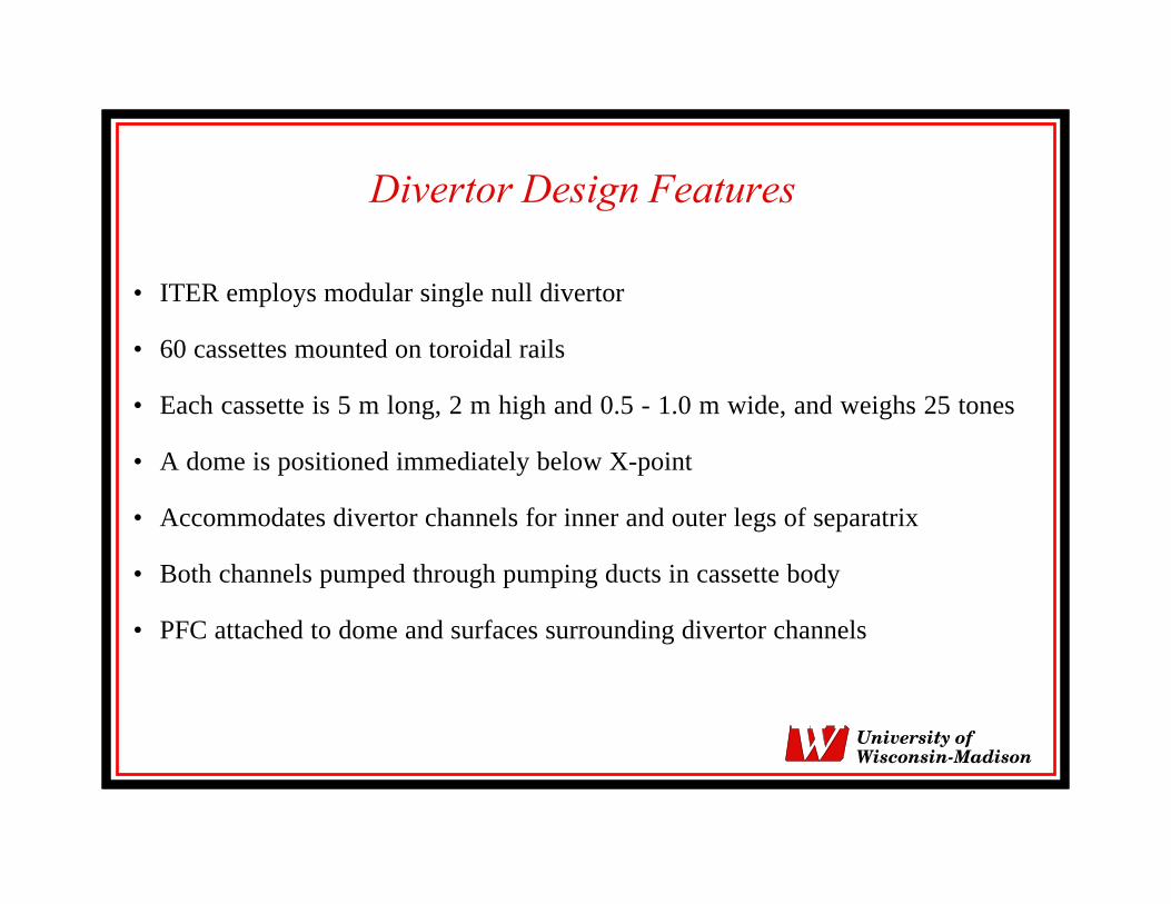
Divertor Design Features
• ITER employs modular single null divertor
• 60 cassettes mounted on toroidal rails
• Each cassette is 5 m long, 2 m high and 0.5 - 1.0 m wide, and weighs 25 tones
• A dome is positioned immediately below X-point
• Accommodates divertor channels for inner and outer legs of separatrix
• Both channels pumped through pumping ducts in cassette body
• PFC attached to dome and surfaces surrounding divertor channels
University ofWisconsin-Madison
Divertor Cassette Design Options
Divertor cassette design has undergone several changes to improveits performance
Two design options considered:
– Design option with wings and gas boxes under dome– The reference design including extended dome, elimination of
wings, and using a thick liner in front of pumping duct
University ofWisconsin-Madison
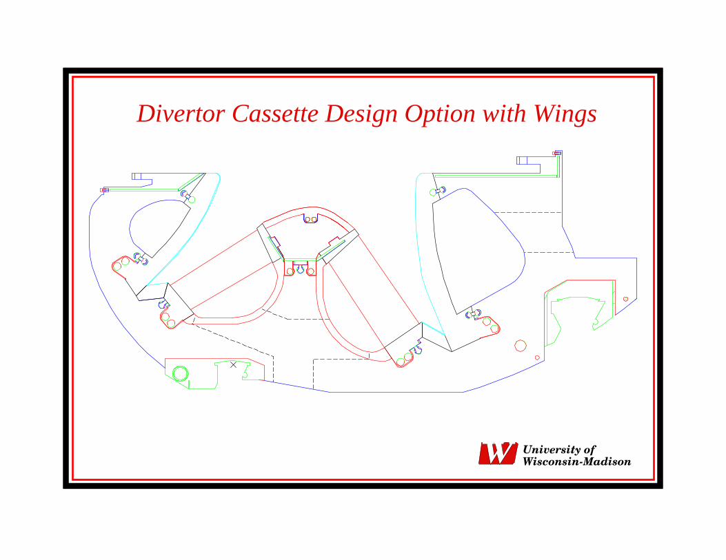
Divertor Cassette Design Option with Wings
University ofWisconsin-Madison
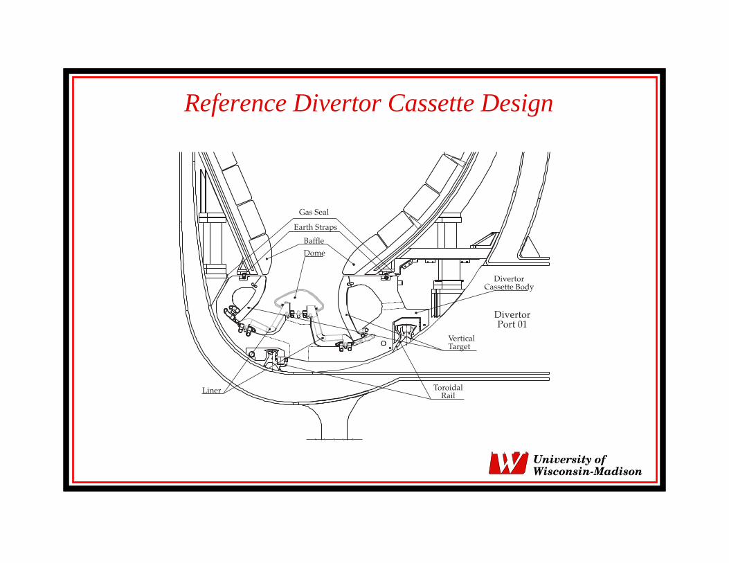
Reference Divertor Cassette Design
University ofWisconsin-Madison
Objectives
• Determine neutron wall loading distribution
• Calculate nuclear parameters in the divertor cassette options
• Assess feasibility of vacuum vessel rewelding in the divertor region
• Evaluate damage and heating in the TF coils due to streaming in divertorports
• Results presented for the cassette design option with gas boxes and wingsand for the current reference design taking into account changes ingeometry and material composition
University ofWisconsin-Madison
Calculation Procedure
• Detailed 3-D geometrical configuration of ITER divertor cassette modeled
• Continuous energy Monte Carlo code MCNP-4A
• Cross section data based on FENDL-1
• Source sampled from pointwise source distribution in ITER plasma
• Used 50,000 source particles yielding statistical uncertainties less than 5%
• Results normalized to nominal fusion power of 1500 MW
• End of life parameters normalized to fluence of 1 MW.a/m2
University ofWisconsin-Madison
3-D Divertor Cassette Model
• Geometrical complexity mandates 3-D modeling
• Model represents a nine degree toroidal sector (1/40) of ITER
• It includes one and half cassettes with associated 1 cm gaps
• Each cassette divided into 103 regions to provide detailed spatialdistribution of nuclear heating and radiation damage
• Layered configurations of dome PFC and vertical targets modeledaccurately
• Separate regions included to represent mechanical attachments andcoolant pipe connections
University ofWisconsin-Madison
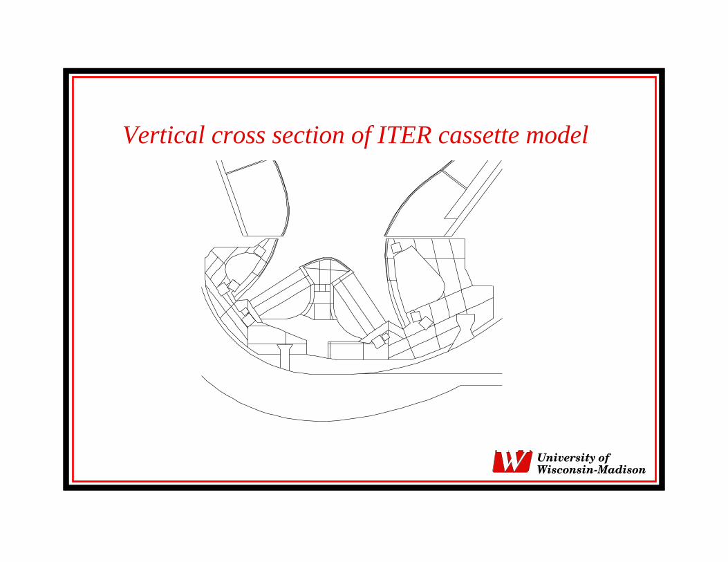
Vertical cross section of ITER cassette model
University ofWisconsin-Madison
Integrated 3-D Model
• Integrated model includes FW, blanket with coolant manifolds and back plates,VV, TF coils, central solenoid, and PF coils
• While Be is used as PFC at FW, tungsten is used for baffle modules above thedivertor cassette
• All toroidal and poloidal gaps included
• Major VV penetrations included
• Model includes half a TF coil and half a divertor port
• Divertor port wall is 20 cm thick and consist of 80% 316SS and 20% water. Noadditional shielding is included
University ofWisconsin-Madison
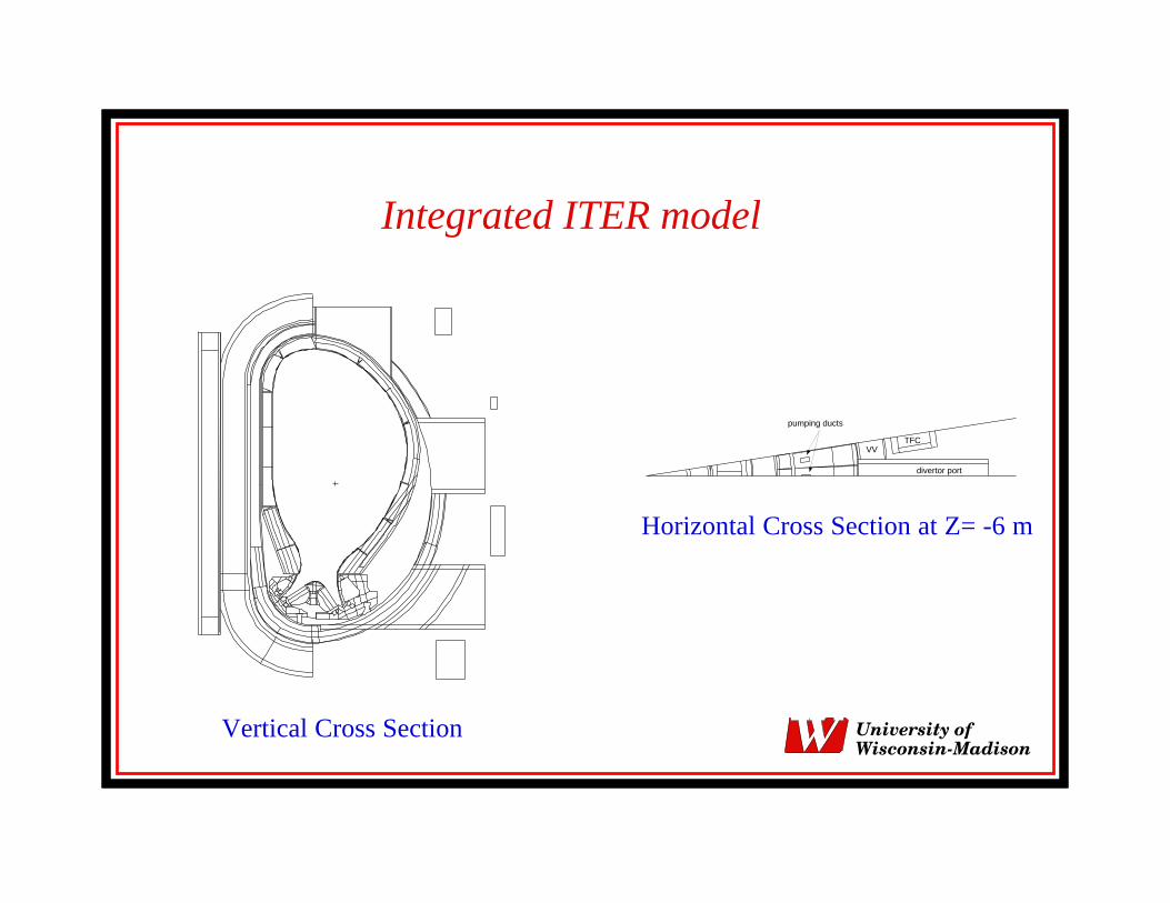
Integrated ITER model
Vertical Cross Section
divertor port
pumping ducts
TFCVV
Horizontal Cross Section at Z= -6 m
University ofWisconsin-Madison
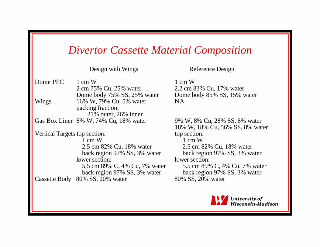
Divertor Cassette Material Composition
Design with Wings Reference Design
Dome PFC 1 cm W 1 cm W2 cm 75% Cu, 25% water 2.2 cm 83% Cu, 17% waterDome body 75% SS, 25% water Dome body 85% SS, 15% water
Wings 16% W, 79% Cu, 5% water NApacking fraction:
21% outer, 26% innerGas Box Liner 8% W, 74% Cu, 18% water 9% W, 8% Cu, 28% SS, 6% water
18% W, 18% Cu, 56% SS, 8% waterVertical Targets top section: top section:
1 cm W 1 cm W2.5 cm 82% Cu, 18% water 2.5 cm 82% Cu, 18% waterback region 97% SS, 3% water back region 97% SS, 3% water
lower section: lower section:5.5 cm 89% C, 4% Cu, 7% water 5.5 cm 89% C, 4% Cu, 7% waterback region 97% SS, 3% water back region 97% SS, 3% water
Cassette Body 80% SS, 20% water 80% SS, 20% water
University ofWisconsin-Madison
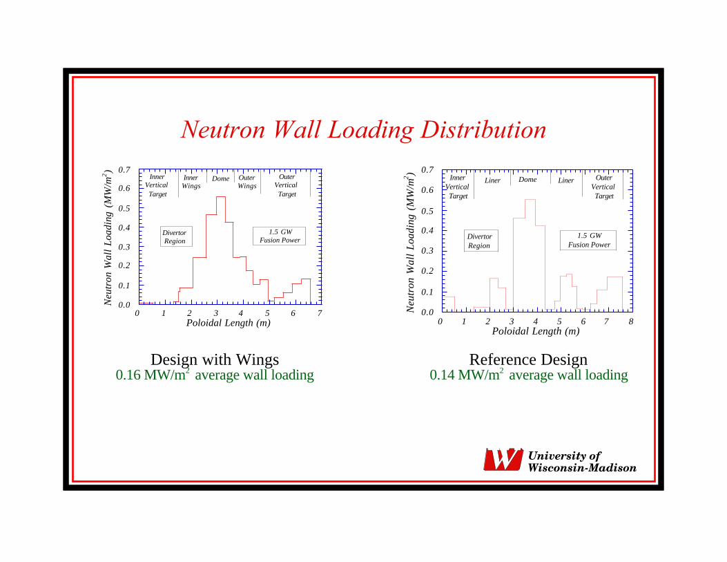
Neutron Wall Loading Distribution
0.0
0.1
0.2
0.3
0.4
0.5
0.6
0.7
0 1 2 3 4 5 6Poloidal Length (m)
7
OuterVertical Target
DivertorRegion
Ne
utr
on
Wa
ll L
oa
din
g (
MW
/m2)
1.5 GWFusion Power
Inner Vertical Target
InnerWings
Dome Outer Wings
Design with Wings0.16 MW/m2 average wall loading
0.0
0.1
0.2
0.3
0.4
0.5
0.6
0.7
0 1 2 3 4 5 6 7 8Poloidal Length (m)
OuterVertical Target
DivertorRegion
Ne
utr
on
Wa
ll L
oa
din
g (
MW
/m2 )
1.5 GWFusion Power
Inner Vertical Target
Liner Dome Liner
Reference Design0.14 MW/m2 average wall loading
University ofWisconsin-Madison
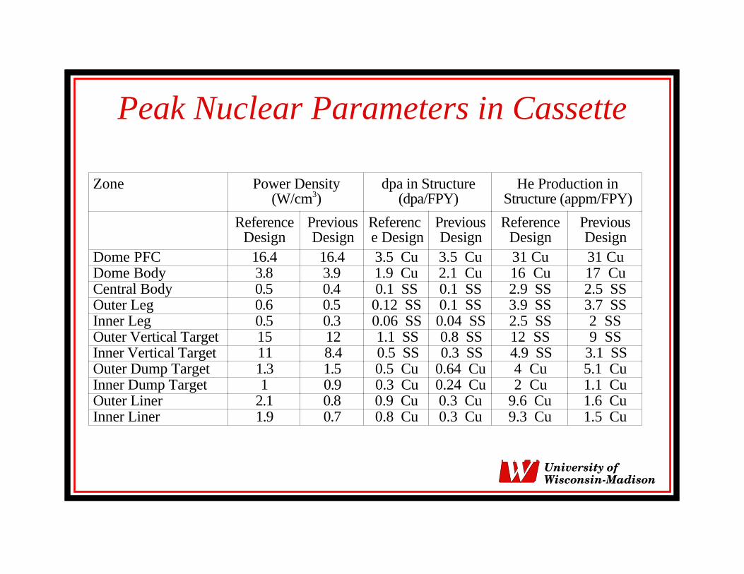
Peak Nuclear Parameters in Cassette
Zone Power Density(W/cm3)
dpa in Structure(dpa/FPY)
He Production inStructure (appm/FPY)
ReferenceDesign
PreviousDesign
Reference Design
PreviousDesign
ReferenceDesign
PreviousDesign
Dome PFC 16.4 16.4 3.5 Cu 3.5 Cu 31 Cu 31 CuDome Body 3.8 3.9 1.9 Cu 2.1 Cu 16 Cu 17 CuCentral Body 0.5 0.4 0.1 SS 0.1 SS 2.9 SS 2.5 SSOuter Leg 0.6 0.5 0.12 SS 0.1 SS 3.9 SS 3.7 SSInner Leg 0.5 0.3 0.06 SS 0.04 SS 2.5 SS 2 SSOuter Vertical Target 15 12 1.1 SS 0.8 SS 12 SS 9 SSInner Vertical Target 11 8.4 0.5 SS 0.3 SS 4.9 SS 3.1 SSOuter Dump Target 1.3 1.5 0.5 Cu 0.64 Cu 4 Cu 5.1 CuInner Dump Target 1 0.9 0.3 Cu 0.24 Cu 2 Cu 1.1 CuOuter Liner 2.1 0.8 0.9 Cu 0.3 Cu 9.6 Cu 1.6 CuInner Liner 1.9 0.7 0.8 Cu 0.3 Cu 9.3 Cu 1.5 Cu
University ofWisconsin-Madison
Nuclear Parameters in Divertor Cassette
• Largest heating and damage occurs in the dome PFC with fullview of the plasma. Power density in the W PFC at the domeis 16.4 W/cm3
• W PFC at top of vertical targets experience relatively highlevels of heating and damage
• Heating and damage values drop rapidly as one moves deeperin cassette body
• Nuclear parameters in inboard side of cassette are lower thanin outboard side
University ofWisconsin-Madison
Impact of Changes in Reference Design
• Nuclear heating and damage in dome PFC of reference design aresimilar to those in design option with wings
• Coolant connections and mechanical attachments at bottom ofdome experience a factor of 20 lower heating and damage
• Configuration of outer vertical target results in upper part havingfull view of plasma and higher nuclear parameters
• Nuclear parameters in dump targets slightly different due todifferent configurations of vertical targets and dump targets
• Liners exposed to direct source neutrons except for top regionsshielded by extended dome
University ofWisconsin-Madison
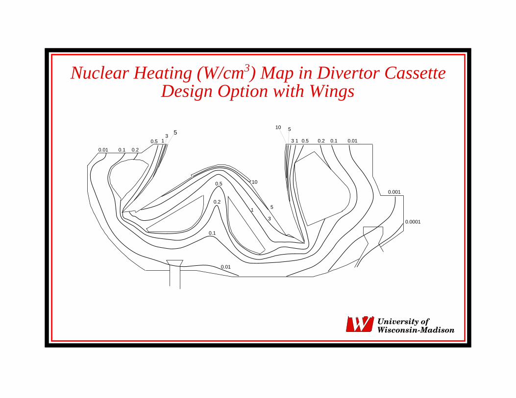
Nuclear Heating (W/cm3) Map in Divertor CassetteDesign Option with Wings
10
5
3
1
0.5
0.2
0.1
0.01
0.01 0.1 0.2
0.5 13
0.010.10.20.513
5105
0.001
0.0001
University ofWisconsin-Madison
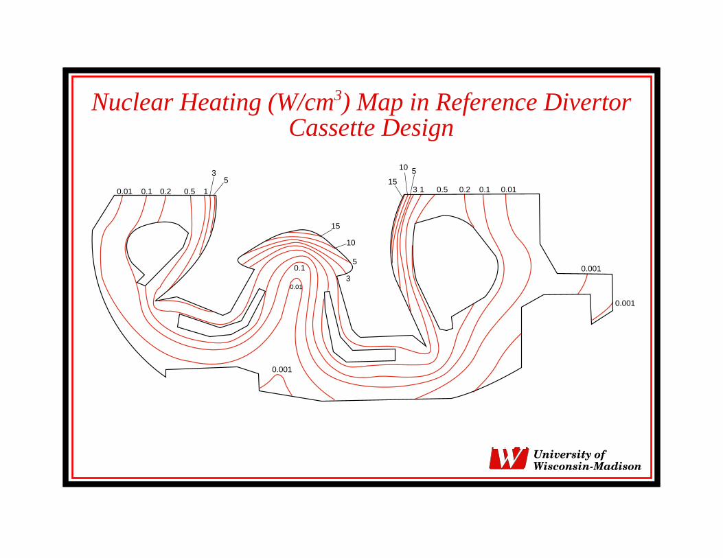
Nuclear Heating (W/cm3) Map in Reference DivertorCassette Design
0.01 0.1 0.2 0.5 1
35
0.001
15
10 5
3 1 0.5
15
10
5
30.1
0.01
0.001
0.001
0.010.10.2
University ofWisconsin-Madison
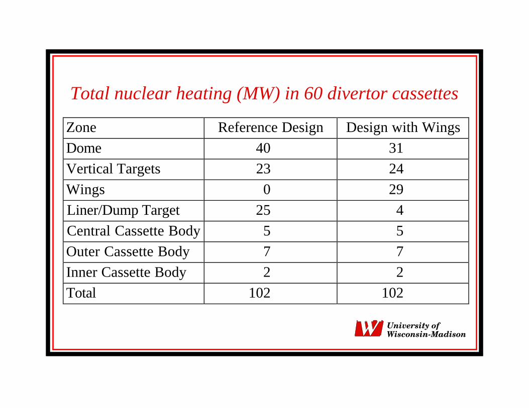
Total nuclear heating (MW) in 60 divertor cassettes
Zone Reference Design Design with Wings
Dome 40 31
Vertical Targets 23 24
Wings 0 29
Liner/Dump Target 25 4
Central Cassette Body 5 5
Outer Cassette Body 7 7
Inner Cassette Body 2 2
Total 102 102
University ofWisconsin-Madison
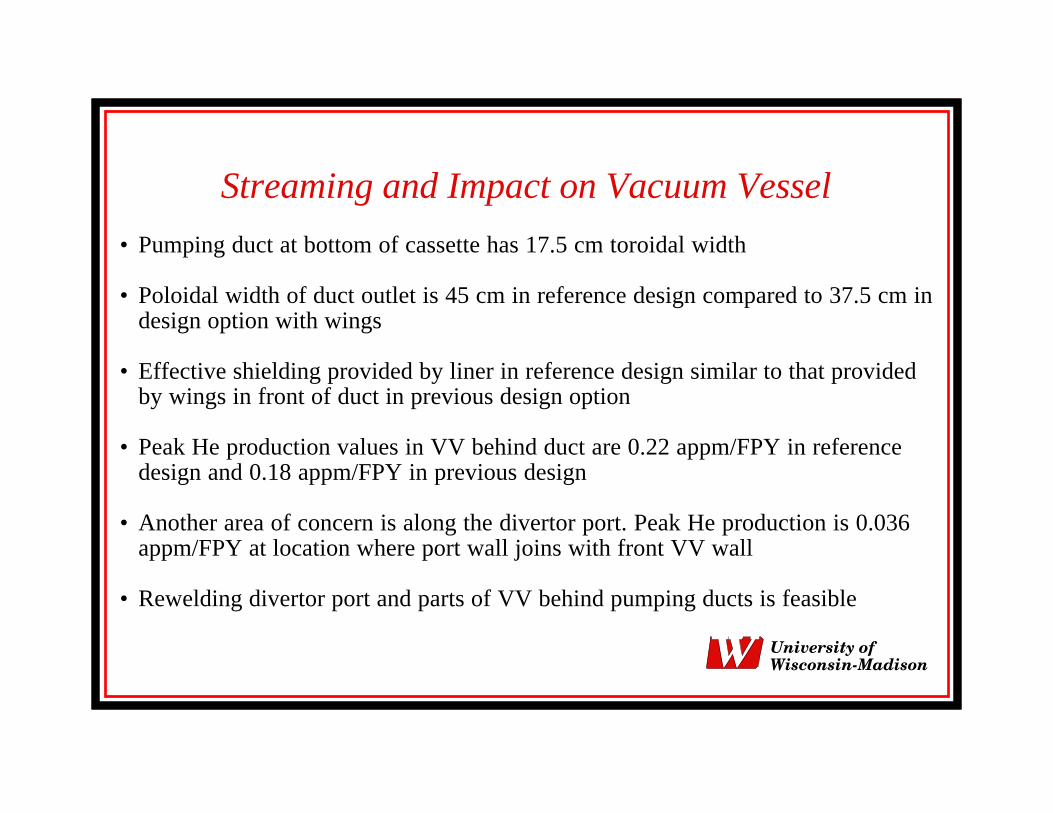
Streaming and Impact on Vacuum Vessel
• Pumping duct at bottom of cassette has 17.5 cm toroidal width
• Poloidal width of duct outlet is 45 cm in reference design compared to 37.5 cm indesign option with wings
• Effective shielding provided by liner in reference design similar to that providedby wings in front of duct in previous design option
• Peak He production values in VV behind duct are 0.22 appm/FPY in referencedesign and 0.18 appm/FPY in previous design
• Another area of concern is along the divertor port. Peak He production is 0.036appm/FPY at location where port wall joins with front VV wall
• Rewelding divertor port and parts of VV behind pumping ducts is feasible
University ofWisconsin-Madison
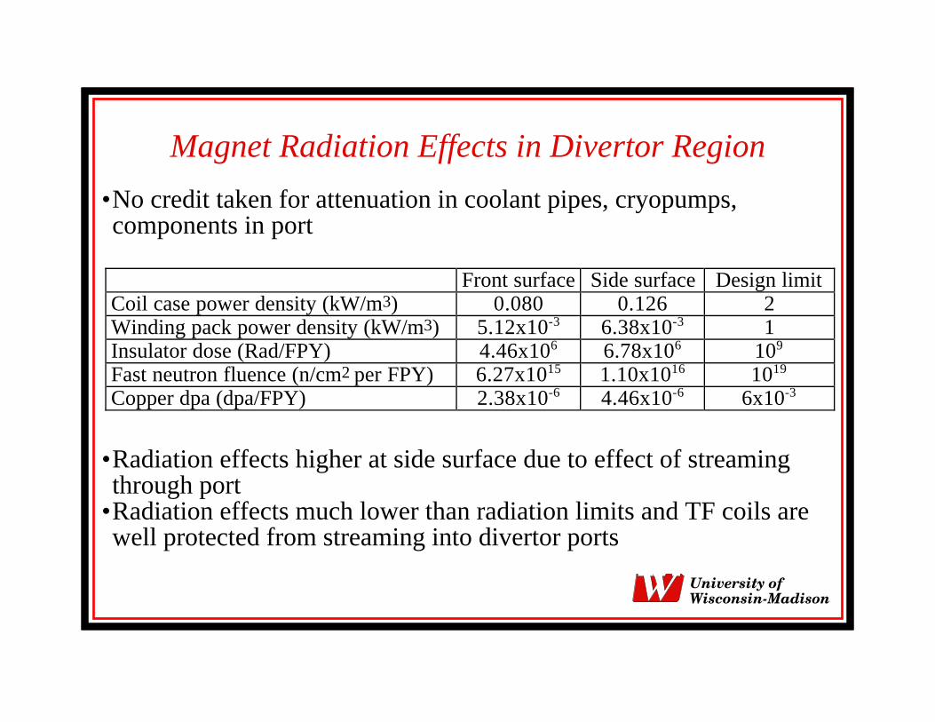
Magnet Radiation Effects in Divertor Region
•No credit taken for attenuation in coolant pipes, cryopumps,components in port
Front surface Side surface Design limitCoil case power density (kW/m3) 0.080 0.126 2Winding pack power density (kW/m3) 5.12x10⁻³ 6.38x10⁻³ 1Insulator dose (Rad/FPY) 4.46x10⁶ 6.78x10⁶ 109
Fast neutron fluence (n/cm2 per FPY) 6.27x10¹⁵ 1.10x10¹⁶ 1019
Copper dpa (dpa/FPY) 2.38x10⁻⁶ 4.46x10⁻⁶ 6x10⁻³
•Radiation effects higher at side surface due to effect of streamingthrough port
•Radiation effects much lower than radiation limits and TF coils arewell protected from streaming into divertor ports
University ofWisconsin-Madison
Total Nuclear Heating in TF Coils
• Total nuclear heating in parts of 20 TF coils in divertor region is 2.1 kW with 1.6kW contributed by parts adjacent to divertor port
• Calculations that included inter-coil structures and midplane port streaming gavetotal heating of 7.6 kW in TF coils and inter-coil structure in divertor region
• A 23 cm thick plate (75% SS and 25% water) is needed between VV and blanketto allow personnel access two weeks after shutdown in area around divertor port
• This shield reduces nuclear heating in divertor region to 0.5 kW
• Total nuclear heating in TF coils should not exceed 17 kW
• Adding calculated nuclear heating for different regions of the TF coils includingstreaming through all VV ports yields total nuclear heating of about 7 kW
University ofWisconsin-Madison
Conclusions• Peak neutron wall loading is 0.56 MW/m2 at dome
• Largest heating and damage is in dome PFC with power density of 16.4 W/cm3
• Nuclear parameters in inboard side of cassette lower than in outboard side
• Local nuclear parameters in components of reference cassette design are similaror lower than in cassette design option with wings
• Total nuclear heating in the 60 divertor cassettes is 102 MW for both designs
• Peak helium production in VV and divertor port implies that rewelding is feasible
• TF coils are well protected from radiation streaming into divertor ports
• Total heating in TF coils and inter-coil structure in divertor region is only 0.5 kWwhen a 23 cm plate shield used between the VV and blanket above divertor port
University ofWisconsin-Madison