Embed Size (px)
Citation preview
J A Snipes, 28th IAEA Fusion Energy Conference, Nice 10 – 15 May 2021
© 2021, ITER Organization
Page 1
IDM: 4ZL4T2
ITER PLASMA CONTROL SYSTEM FINAL DESIGN AND PREPARATION FOR FIRST
PLASMA
Joseph A Snipes
on behalf of the ITER PCS Design Team and
ITER Organization
Disclaimer: The views and opinions expressed herein do not necessarily reflect those of the ITER Organization
J A Snipes, 28th IAEA Fusion Energy Conference, Nice 10 – 15 May 2021
© 2021, ITER Organization
Page 2
IDM: 4ZL4T2
Outline Plasma Control System (PCS) Final Design for First
Plasma• Nominal control and Exception Handling• PCS Configuration and Architecture• Systems engineering and design assessment• PCS commissioning
ITER Research Plan – first operation phase• Integrated Commissioning (IC)• First Plasma Campaign (FP)• Engineering Operation (EO)
Conclusion
J A Snipes, 28th IAEA Fusion Energy Conference, Nice 10 – 15 May 2021
© 2021, ITER Organization
Page 3
IDM: 4ZL4T2
ITER Plasma Control System Final Design Scope The PCS is key to integrated ITER operation The PCS Final Design for FP was performed by ITER Organization and
a team of external plasma control experts from EU, Russian Federation and US, building on the Conceptual and Preliminary designs
The PCS Final Design for FP includes:
• Basic magnetic control of Central Solenoid (CS) and Poloidal Field (PF) coils
• Kinetic control of gas injection system (GIS) & Electron Cyclotron Heating (ECH)
• Exception handling due to plasma or plant system events
• Pulse schedule requirements to reconfigure the PCS for each pulse
• Architecture required for FP up through Fusion Power Operation (FPO)
• Systems engineering approach and design assessment
• PCS commissioning plans
J A Snipes, 28th IAEA Fusion Energy Conference, Nice 10 – 15 May 2021
© 2021, ITER Organization
Page 4
IDM: 4ZL4T2
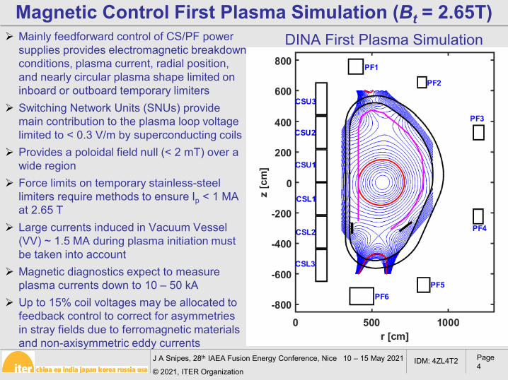
Mainly feedforward control of CS/PF power supplies provides electromagnetic breakdown conditions, plasma current, radial position, and nearly circular plasma shape limited on inboard or outboard temporary limiters
Switching Network Units (SNUs) provide main contribution to the plasma loop voltage limited to < 0.3 V/m by superconducting coils
Provides a poloidal field null (< 2 mT) over a wide region
Force limits on temporary stainless-steel limiters require methods to ensure Ip < 1 MA at 2.65 T
Large currents induced in Vacuum Vessel (VV) ~ 1.5 MA during plasma initiation must be taken into account
Magnetic diagnostics expect to measure plasma currents down to 10 – 50 kA
Up to 15% coil voltages may be allocated to feedback control to correct for asymmetries in stray fields due to ferromagnetic materials and non-axisymmetric eddy currents
Magnetic Control First Plasma Simulation (Bt = 2.65T)DINA First Plasma Simulation
J A Snipes, 28th IAEA Fusion Energy Conference, Nice 10 – 15 May 2021
© 2021, ITER Organization
Page 5
IDM: 4ZL4T2
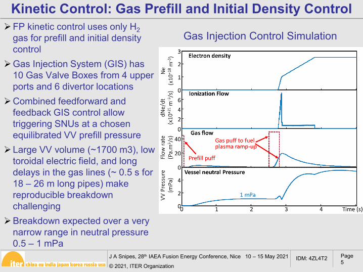
FP kinetic control uses only H2gas for prefill and initial density control
Gas Injection System (GIS) has 10 Gas Valve Boxes from 4 upper ports and 6 divertor locations
Combined feedforward and feedback GIS control allow triggering SNUs at a chosen equilibrated VV prefill pressure
Large VV volume (~1700 m3), low toroidal electric field, and long delays in the gas lines (~ 0.5 s for 18 – 26 m long pipes) make reproducible breakdown challenging
Breakdown expected over a very narrow range in neutral pressure 0.5 – 1 mPa
Kinetic Control: Gas Prefill and Initial Density Control
Gas Injection Control Simulation
J A Snipes, 28th IAEA Fusion Energy Conference, Nice 10 – 15 May 2021
© 2021, ITER Organization
Page 6
IDM: 4ZL4T2
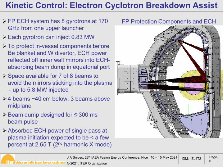
Kinetic Control: Electron Cyclotron Breakdown Assist
FP ECH system has 8 gyrotrons at 170 GHz from one upper launcher
Each gyrotron can inject 0.83 MWTo protect in-vessel components before
Be blanket and W divertor, ECH power reflected off inner wall mirrors into ECH-absorbing beam dump in equatorial port
Space available for 7 of 8 beams to avoid the mirrors sticking into the plasma – up to 5.8 MW injected
4 beams ~40 cm below, 3 beams above midplane
Beam dump designed for ≤ 300 msbeam pulse
Absorbed ECH power of single pass at plasma initiation expected to be < a few percent at 2.65 T (2nd harmonic X-mode)
FP Protection Components and ECH
J A Snipes, 28th IAEA Fusion Energy Conference, Nice 10 – 15 May 2021
© 2021, ITER Organization
Page 7
IDM: 4ZL4T2
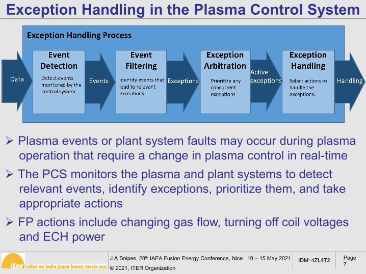
Exception Handling in the Plasma Control System
Plasma events or plant system faults may occur during plasma operation that require a change in plasma control in real-time
The PCS monitors the plasma and plant systems to detect relevant events, identify exceptions, prioritize them, and take appropriate actions
FP actions include changing gas flow, turning off coil voltages and ECH power
J A Snipes, 28th IAEA Fusion Energy Conference, Nice 10 – 15 May 2021
© 2021, ITER Organization
Page 8
IDM: 4ZL4T2
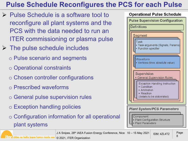
Pulse Schedule is a software tool to reconfigure all plant systems and the PCS with the data needed to run an ITER commissioning or plasma pulse
The pulse schedule includeso Pulse scenario and segments
o Operational constraints
o Chosen controller configurations
o Prescribed waveforms
o General pulse supervision rules
o Exception handling policies
o Configuration information for all operational plant systems
Pulse Schedule Reconfigures the PCS for each Pulse
J A Snipes, 28th IAEA Fusion Energy Conference, Nice 10 – 15 May 2021
© 2021, ITER Organization
Page 9
IDM: 4ZL4T2
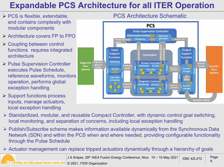
PCS is flexible, extendable, and contains complexity withmodular components
Architecture covers FP to FPO Coupling between control
functions requires integrated architecture
Pulse Supervision Controller executes Pulse Schedule, reference waveforms, monitors operation, performs global exception handling
Support functions process inputs, manage actuators, local exception handling
Expandable PCS Architecture for all ITER Operation
Standardized, modular, and reusable Compact Controller, with dynamic control goal switching, local monitoring, and separation of concerns, including local exception handling
Publish/Subscribe scheme makes information available dynamically from the Synchronous Data Network (SDN) and within the PCS when and where needed, providing configurable functionality through the Pulse Schedule
Actuator management can replace tripped actuators dynamically through a hierarchy of goals
PCS Architecture Schematic
J A Snipes, 28th IAEA Fusion Energy Conference, Nice 10 – 15 May 2021
© 2021, ITER Organization
Page 10
IDM: 4ZL4T2
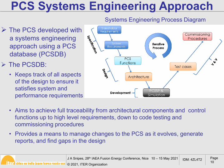
PCS Systems Engineering Approach
The PCS developed with a systems engineering approach using a PCS database (PCSDB)
The PCSDB:• Keeps track of all aspects
of the design to ensure it satisfies system and performance requirements
Systems Engineering Process Diagram
• Aims to achieve full traceability from architectural components and control functions up to high level requirements, down to code testing and commissioning procedures
• Provides a means to manage changes to the PCS as it evolves, generate reports, and find gaps in the design
J A Snipes, 28th IAEA Fusion Energy Conference, Nice 10 – 15 May 2021
© 2021, ITER Organization
Page 11
IDM: 4ZL4T2
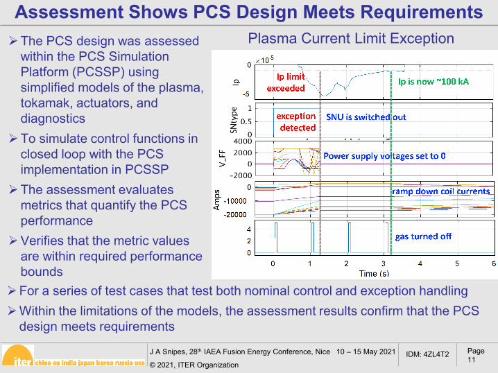
Assessment Shows PCS Design Meets RequirementsPlasma Current Limit Exception
For a series of test cases that test both nominal control and exception handlingWithin the limitations of the models, the assessment results confirm that the PCS
design meets requirements
The PCS design was assessed within the PCS Simulation Platform (PCSSP) using simplified models of the plasma, tokamak, actuators, and diagnostics
To simulate control functions in closed loop with the PCS implementation in PCSSP
The assessment evaluates metrics that quantify the PCS performance
Verifies that the metric values are within required performance bounds
J A Snipes, 28th IAEA Fusion Energy Conference, Nice 10 – 15 May 2021
© 2021, ITER Organization
Page 12
IDM: 4ZL4T2
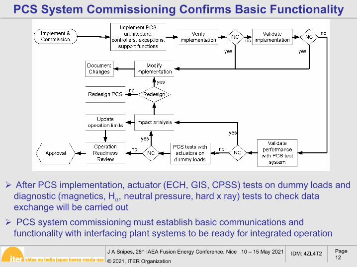
PCS System Commissioning Confirms Basic Functionality
After PCS implementation, actuator (ECH, GIS, CPSS) tests on dummy loads and diagnostic (magnetics, Hα, neutral pressure, hard x ray) tests to check data exchange will be carried out
PCS system commissioning must establish basic communications and functionality with interfacing plant systems to be ready for integrated operation
J A Snipes, 28th IAEA Fusion Energy Conference, Nice 10 – 15 May 2021
© 2021, ITER Organization
Page 13
IDM: 4ZL4T2
ITER Research Plan (https://www.iter.org/technical-reports?id=9) begins with1. Integrated Commissioning
Central control systems: CODAC, PCS, Central Interlock System(CIS) and Central Safety System (CSS) must be commissionedto ensure control and protection systems function correctly
Integrated Commissioning begins with VV and Cryostat closure,pump down, baking, Gas Injection System and Glow DischargeCleaning (GDC)
Commission magnets and power supplies to half current and halfTF of 2.65 T
Magnetic diagnostic commissioning Commission ECH
2. First Plasma to achieve Ip > 100 kA for > 100 ms3. Engineering Operation to commission magnets to full
current
ITER Research Plan First Operation Phase
J A Snipes, 28th IAEA Fusion Energy Conference, Nice 10 – 15 May 2021
© 2021, ITER Organization
Page 14
IDM: 4ZL4T2
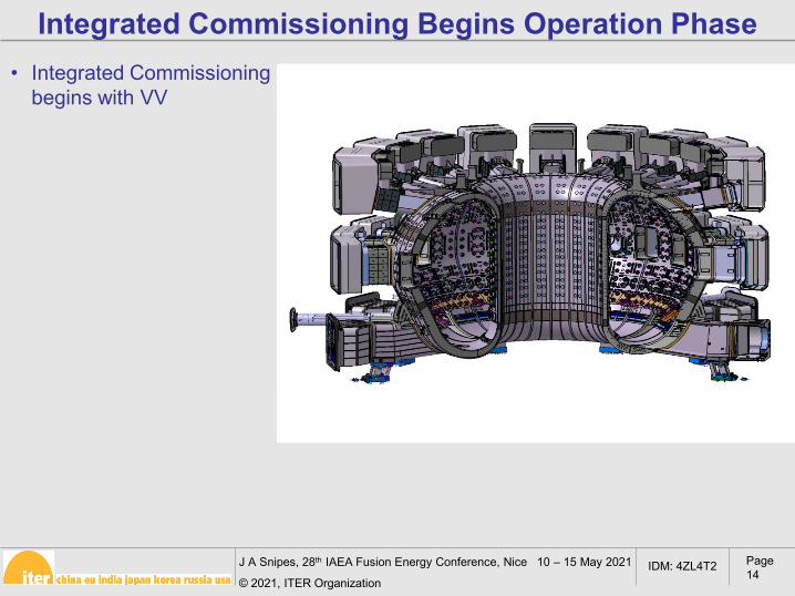
Integrated Commissioning Begins Operation Phase• Integrated Commissioning
begins with VV
J A Snipes, 28th IAEA Fusion Energy Conference, Nice 10 – 15 May 2021
© 2021, ITER Organization
Page 15
IDM: 4ZL4T2
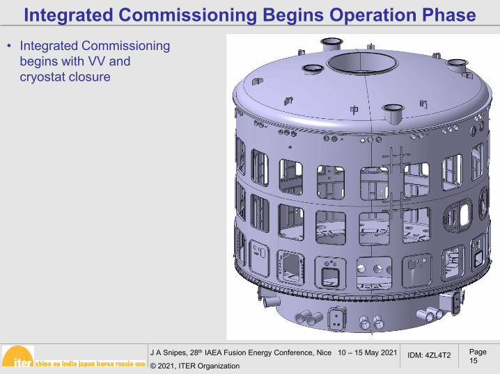
Integrated Commissioning Begins Operation Phase• Integrated Commissioning
begins with VV and cryostat closure
J A Snipes, 28th IAEA Fusion Energy Conference, Nice 10 – 15 May 2021
© 2021, ITER Organization
Page 16
IDM: 4ZL4T2
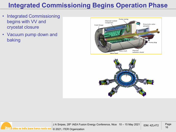
Integrated Commissioning Begins Operation Phase• Integrated Commissioning
begins with VV and cryostat closure
• Vacuum pump down and baking
J A Snipes, 28th IAEA Fusion Energy Conference, Nice 10 – 15 May 2021
© 2021, ITER Organization
Page 17
IDM: 4ZL4T2
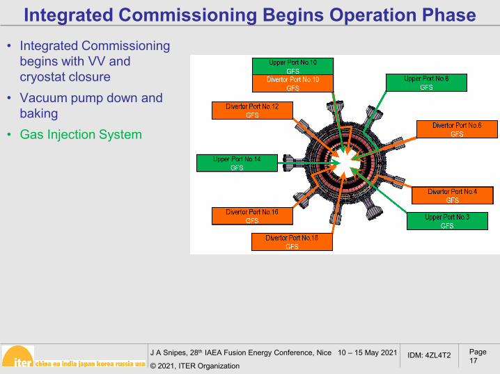
Integrated Commissioning Begins Operation Phase• Integrated Commissioning
begins with VV and cryostat closure
• Vacuum pump down and baking
• Gas Injection System
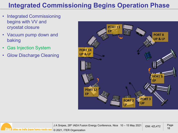
J A Snipes, 28th IAEA Fusion Energy Conference, Nice 10 – 15 May 2021
© 2021, ITER Organization
Page 18
IDM: 4ZL4T2
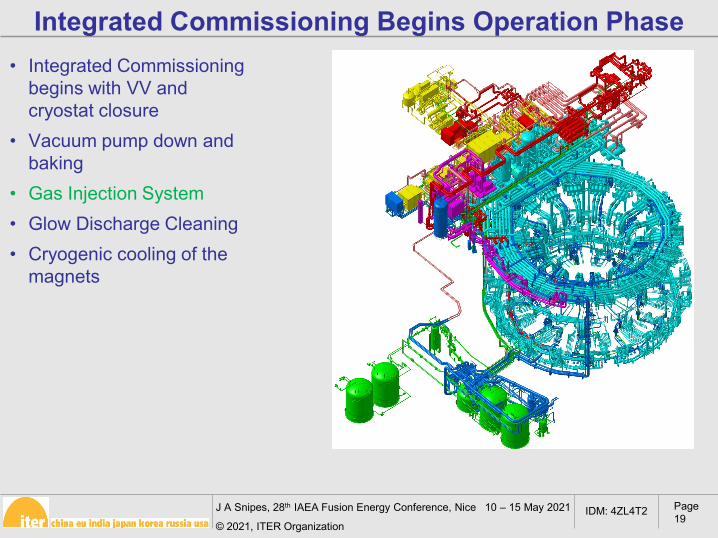
Integrated Commissioning Begins Operation Phase• Integrated Commissioning
begins with VV and cryostat closure
• Vacuum pump down and baking
• Gas Injection System• Glow Discharge Cleaning
J A Snipes, 28th IAEA Fusion Energy Conference, Nice 10 – 15 May 2021
© 2021, ITER Organization
Page 19
IDM: 4ZL4T2
Integrated Commissioning Begins Operation Phase• Integrated Commissioning
begins with VV and cryostat closure
• Vacuum pump down and baking
• Gas Injection System• Glow Discharge Cleaning • Cryogenic cooling of the
magnets
J A Snipes, 28th IAEA Fusion Energy Conference, Nice 10 – 15 May 2021
© 2021, ITER Organization
Page 20
IDM: 4ZL4T2
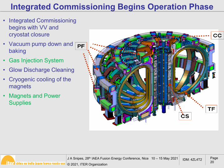
Integrated Commissioning Begins Operation Phase• Integrated Commissioning
begins with VV and cryostat closure
• Vacuum pump down and baking
• Gas Injection System• Glow Discharge Cleaning • Cryogenic cooling of the
magnets• Magnets and Power
Supplies
J A Snipes, 28th IAEA Fusion Energy Conference, Nice 10 – 15 May 2021
© 2021, ITER Organization
Page 21
IDM: 4ZL4T2
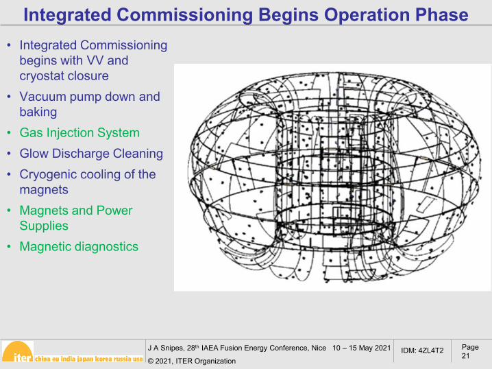
Integrated Commissioning Begins Operation Phase• Integrated Commissioning
begins with VV and cryostat closure
• Vacuum pump down and baking
• Gas Injection System• Glow Discharge Cleaning • Cryogenic cooling of the
magnets• Magnets and Power
Supplies• Magnetic diagnostics
J A Snipes, 28th IAEA Fusion Energy Conference, Nice 10 – 15 May 2021
© 2021, ITER Organization
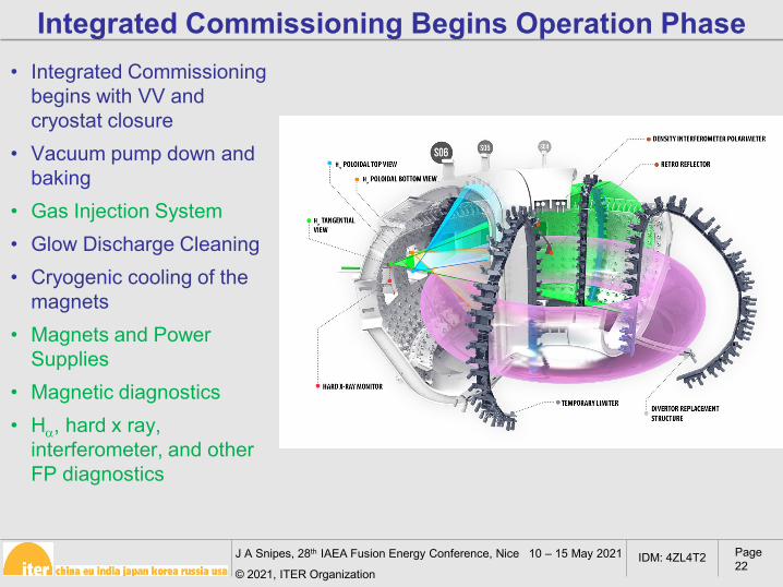
Page 22
IDM: 4ZL4T2
Integrated Commissioning Begins Operation Phase• Integrated Commissioning
begins with VV and cryostat closure
• Vacuum pump down and baking
• Gas Injection System• Glow Discharge Cleaning • Cryogenic cooling of the
magnets• Magnets and Power
Supplies• Magnetic diagnostics • Hα, hard x ray,
interferometer, and other FP diagnostics
J A Snipes, 28th IAEA Fusion Energy Conference, Nice 10 – 15 May 2021
© 2021, ITER Organization
Page 23
IDM: 4ZL4T2
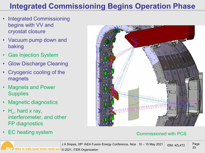
• Integrated Commissioning begins with VV and cryostat closure
• Vacuum pump down and baking
• Gas Injection System• Glow Discharge Cleaning • Cryogenic cooling of the
magnets• Magnets and Power
Supplies• Magnetic diagnostics • Hα, hard x ray,
interferometer, and other FP diagnostics
• EC heating system
Integrated Commissioning Begins Operation Phase
Commissioned with PCS
J A Snipes, 28th IAEA Fusion Energy Conference, Nice 10 – 15 May 2021
© 2021, ITER Organization
Page 24
IDM: 4ZL4T2
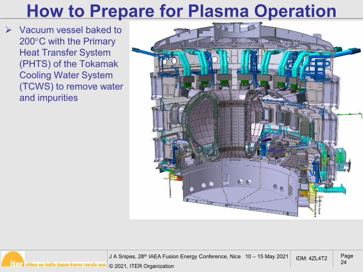
How to Prepare for Plasma Operation Vacuum vessel baked to
200°C with the Primary Heat Transfer System (PHTS) of the Tokamak Cooling Water System (TCWS) to remove water and impurities
J A Snipes, 28th IAEA Fusion Energy Conference, Nice 10 – 15 May 2021
© 2021, ITER Organization
Page 25
IDM: 4ZL4T2
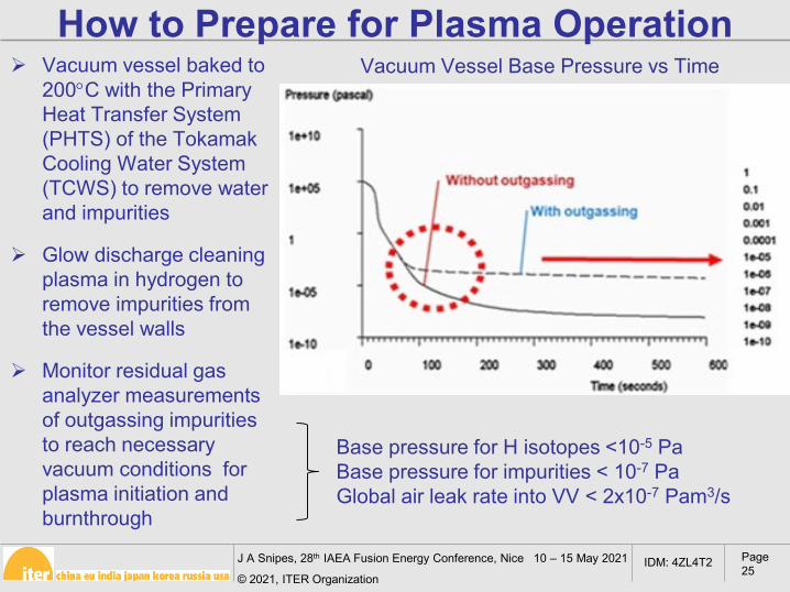
Vacuum vessel baked to 200°C with the Primary Heat Transfer System (PHTS) of the Tokamak Cooling Water System (TCWS) to remove water and impurities
Glow discharge cleaning plasma in hydrogen to remove impurities from the vessel walls
Monitor residual gas analyzer measurements of outgassing impurities to reach necessary vacuum conditions for plasma initiation and burnthrough
Vacuum Vessel Base Pressure vs Time
Base pressure for H isotopes <10-5 PaBase pressure for impurities < 10-7 PaGlobal air leak rate into VV < 2x10⁻⁷ Pam3/s
How to Prepare for Plasma Operation
J A Snipes, 28th IAEA Fusion Energy Conference, Nice 10 – 15 May 2021
© 2021, ITER Organization
Page 26
IDM: 4ZL4T2
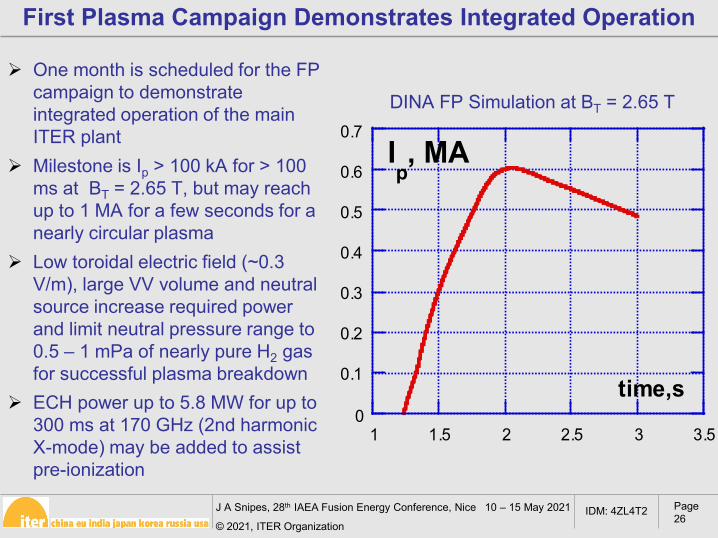
One month is scheduled for the FP campaign to demonstrate integrated operation of the main ITER plant
Milestone is Ip > 100 kA for > 100 ms at BT = 2.65 T, but may reach up to 1 MA for a few seconds for a nearly circular plasma
Low toroidal electric field (~0.3 V/m), large VV volume and neutral source increase required power and limit neutral pressure range to 0.5 – 1 mPa of nearly pure H2 gas for successful plasma breakdown
ECH power up to 5.8 MW for up to 300 ms at 170 GHz (2nd harmonic X-mode) may be added to assist pre-ionization
0
0.1
0.2
0.3
0.4
0.5
0.6
0.7
1 1.5 2 2.5 3 3.5
Ip, MA
time,s
First Plasma Campaign Demonstrates Integrated Operation
DINA FP Simulation at BT = 2.65 T

J A Snipes, 28th IAEA Fusion Energy Conference, Nice 10 – 15 May 2021
© 2021, ITER Organization
Page 27
IDM: 4ZL4T2
EO campaign will commission the TF, CS, PF, and CC magnets to full current to demonstrate capability to achieve nominal plasma current of 15 MA at 5.3 T
Characterize magnet hydraulic, thermal and mechanical behavior
Commission quench detection, interlock fast discharge and tokamak systems monitoring structural stresses
Magnetic axis alignment measurement to position the blanket modules during Assembly Phase II (Pitts, EX/P5-1, Thurs)
Engineering Operation Demonstrates Full Current Capability
If FP was not achieved at 2.65 T, attempts will be made at 5.3 T with improved breakdown conditions
Superconducting Magnet System
J A Snipes, 28th IAEA Fusion Energy Conference, Nice 10 – 15 May 2021
© 2021, ITER Organization
Page 28
IDM: 4ZL4T2
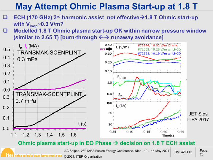
ECH (170 GHz) 3rd harmonic assist not effective1.8 T Ohmic start-up with Vloop~0.3 V/m?
Modelled 1.8 T Ohmic plasma start-up OK within narrow pressure window (similar to 2.65 T) [burn-through runaway avoidance]
.
May Attempt Ohmic Plasma Start-up at 1.8 T
Ohmic plasma start-up in EO Phase decision on 1.8 T ECH assist
Ip
t,s
MA0.5
0.4
0.3
0.2
0.1
0
Ir
TRANSMAK-SCENPLINT0.3 mPa
p
t,s
1.1 1.2 1.3 1.4 1.5 1.6
0.350.3
0.250.2
0.150.1
0.050
TRANSMAK-SCENTPLINT0.7 mPa
0.50.40.30.20.10.00.3
0.2
0.1
0.01.1 1.2 1.3 1.4 1.5 1.6
t (s)
Ip Ir (MA)
JET SipsITPA 2017
J A Snipes, 28th IAEA Fusion Energy Conference, Nice 10 – 15 May 2021
© 2021, ITER Organization
Page 29
IDM: 4ZL4T2
Conclusions ITER tokamak assembly has begun for first VV sector
PF coils 5 and 6 are nearly ready to be installed in the cryostat
The Steady State Electrical Network has been commissioned and Cooling Water System commissioning has begun
The PCS Final Design for First Plasma was approved The ITER Research Plan first operational phase will
begin with Integrated Commissioning, First Plasma and Engineering Operation to commission systems for full current operation to demonstrate capability to achieve 15 MA, 5.3 T in later operation phases