Embed Size (px)
Citation preview

IT6810/IT6811/IT6812 IMPACT TRANSMITTER
Installation Manual
OVERVIEW
The Model IT6810/IT6811/IT6812 Im-pact Transmitter uses new technology to measure impact severity on reciprocating machinery. Impact is a proven method of detecting mechanical looseness on large reciprocating compressors. The Impact Transmitter combines the benefits of this measurement with the convenience of 4-20 mA loop powered sensor technology. It has a built-in piezoelectric crystal sensing element, and uses a timing function as part of its severity determination. An impact event counter and memory device is used to record events meeting a preset amplitude threshold level.
This manual should be used by experienced personnel as a guide to the installation of the Model IT6810/IT6811/IT6812 Impact Transmitter. Selection or installation of equipment should always be accompanied by competent technical assistance. We encourage you to contact the Metrix Instru-ment Co. or its local representative if you require further information..
DOC# M9261 • REV N (July 2017)
IT6810
IT6811
IT6812
NOTE: Before proceeding to install and wire the transmitter, read and thoroughly understand these instructions. Confirm that the
hazardous area rating of the transmitter meets or exceeds that of the area the unit is to be installed in.

Doc# M9261 • REV N (July 2017) Page 2 of 12
MECHANICAL
Mounting LocationThe Impact Transmitter is designed to detect mechanical looseness, not vibration. Therefore, it is mounted with its center bolt perpendicular to the direction of rod motion (figure 1), on top of the crosshead or extension piece, or for a power cylinder (figure 2) mounted on the side of the cylinder, where it will be out of the way of routine inspection or maintenance.
The Impact Transmitter includes both a 1/4-28 and a metric M6 x 1 threaded bolt. Once threaded through the top half of the housing, the bolt becomes captive and will not inadver-tently fall out. It can be bolted to a machined surface, using a 9338 spot face kit, or it can be attached using an optional 1/4-18 NPT threaded adapter. Tighten or remove any loose items on or near the compressor cylinder. Never install on bolted covers or access doors. Since the Impact Transmitter detects mechanical looseness, “rattle noise” from loose external parts can be mistaken for internal loose parts. This will result in false indications of compressor running condition. Ensure that the maximum ambient temperature is not exceeded.
The Impact Transmitter should be mounted such that the recommended baseline reading is 500 mV (rms) or less. For example, in Figure 1 the Separable Compressor (engine separate from compressor), the optimum location for mounting the Impact Transmitter would be on the Crosshead, however, if the baseline reading is greater than 500 mV it is recommended to move the Impact Transmitter to the Distance Piece as shown in Figure 1. For Integral Recip-rocating Compressors (engine is integrated with the compressor), Figure 2, shows the typical mounting locations of the Impact Transmitters. The same methodology for the Compression Cylinder is used for the Integral Compressor as the Separable Compressor. For the Power Cylinder the Impact Transmitter should be mounted on the side of each cylinder, preferably in a location with a baseline reading of 500 mV or less, with height at the top of the travel of the wrist pin (see figure 2). In some applications locating the Impact Transmitters on top of each end of the cylinder banks has proven effective at identifying stuck engine valves.
OUTLINE & DIMENSIONS
UNITS: mm [in]Aprox. Weight: 0.3 kg (0.66 lbs)
Refer to Metrix Datasheet 1009518 for specifications, ordering information, and outlines.

Doc# M9261 • REV N (July 2017) Page 3 of 12
Crankshaft Crosshead
IMPACT TRANSMITTER (Possible Locations)
Distance PieceCompressorCylinder
Figure 1: Sketch of a separable compressor cylinder showing Impact Transmitter location
Figure 2: Sketch of an internal compressor cylinder and engine with Impact Transmitter locations
Machined surfacePrepare a flat surface using an aircraft counter bore* with a minimum 1.0 inch diameter and then tap the center hole for a ¼-28 or M6 x 1 thread allowing for a minimum threaded depth of 3/8 inch (10mm). The tapped hole must be perpendicular to the flat surface within 1.0 degree. Apply a small amount of grease to the mating surface of the transmitter to allow for proper machine contact. With the connector pointed in a convenient direction, thread the appropriate mounting bolt through the housing and into the tapped hole. Torque the bolt to 75 inch-pounds maximum.
NPT Threaded AdapterThis method allows a standard pipe thread to be drilled and tapped into the compressor body. The threaded adapter (Metrix Part Number 9272) has the needed machined surface to insure proper mounting of the transmitter. Install the transmitter as described in the previous para-graph.
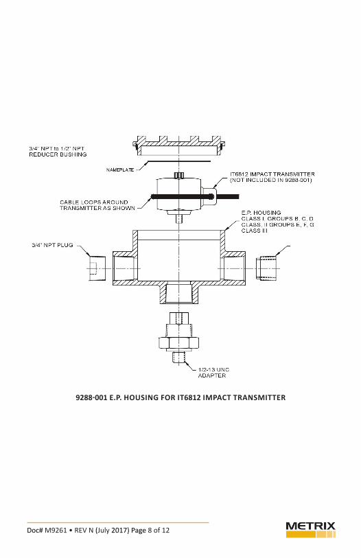
Explosion-proof housing for IT6812: The Metrix p/n 9288-XXX explosion-proof housing allows the transmitter to be installed into a Class I, Div. 1 (Groups B, C, D) area without the use of an intrinsically safe barrier. This housing is available from Metrix. Install the transmitter and housing in a similar manner as described in the previous sections.
*Aircraft counter bores are available from most machine tool suppliers.
Doc# M9261 • REV N (July 2017) Page 4 of 12
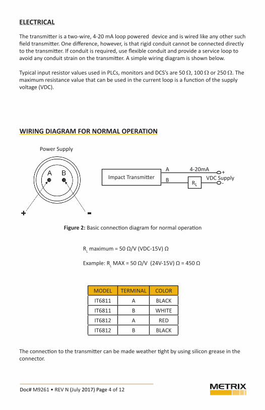
WIRING DIAGRAM FOR NORMAL OPERATION
Power Supply
MODEL TERMINAL COLOR
IT6811 A BLACK
IT6811 B WHITE
IT6812 A RED
IT6812 B BLACK
Impact TransmitterA 4-20mA
B RLVDC Supply
+
-
RL maximum = 50 Ω/V (VDC-15V) Ω
Example: RL MAX = 50 Ω/V (24V-15V) Ω = 450 Ω
The connection to the transmitter can be made weather tight by using silicon grease in the connector.
ELECTRICAL
The transmitter is a two-wire, 4-20 mA loop powered device and is wired like any other such field transmitter. One difference, however, is that rigid conduit cannot be connected directly to the transmitter. If conduit is required, use flexible conduit and provide a service loop to avoid any conduit strain on the transmitter. A simple wiring diagram is shown below.
Typical input resistor values used in PLCs, monitors and DCS’s are 50 W, 100 W or 250 W. The maximum resistance value that can be used in the current loop is a function of the supply voltage (VDC).
Figure 2: Basic connection diagram for normal operation

Doc# M9261 • REV N (July 2017) Page 5 of 12
FIELD ADJUSTMENTS
The impact level threshold adjustment and the impact counter reset-time adjustment should be made in the field. Adjustments are usually done during initial installation and normally do not have to be changed. Both of these adjustments are made by removing the small cap screws located on the top of the transmitter. Small potentiometers become visible when you remove these screws. A miniature screwdriver (Jewelers 1.4 mm slotted) is required to make adjustments to these potentiometers.
Adjustments to the Impact Transmitter should only be made while it is connected to the 6850 Impact Meter.
Setting Threshold LevelWith the impact transmitter installed with the Impact Meter (6850-001) connected to it, and the compressor running, measure the baseline Peak in mV (rms) of the impact transmitter. Each cylinder, whether power or compression, will have its own unique baseline value. Do not average or guess at the value, one needs to measure baseline Peak value in each impact transmitter application. This value should be less than 500 mV. If the baseline Peak value is greater than 500 mV an alternative location for the impact transmitter is recommended, or a different impact transmitter may be required.
Assuming a smooth running compressor, adjust the Threshold Level to 2 to 3 times the baseline Peak value. For high baseline Peak locations (>400 mV) a 2x the baseline would be a better starting point and for lower baseline Peak locations (<300 mV) a 3x baseline Peak value would be appropriate. Remember use the actual baseline Peak value measured for the particular measurement location to obtain the Threshold Level.
Examples: An impact transmitter measuring the impact on a compression cylinder has a baseline Peak value of 250 mV as measured with the Impact Meter (6850-001), the Thresh-old Level should be set at 750 mV (3 x 250 mV = 750 mV). An impact transmitter measuring the impact on a power cylinder has a baseline Peak value of 350 mV as measured with the Impact Meter (6850-001), the Threshold Level should be set at 875 mV (2.5 x 350 mV = 875 mV). An impact transmitter measuring the impact on a power cylinder has a baseline Peak value of 450 mV as measured with the Impact Meter (6850-001), the Threshold Level should be set at 900 mV (2 x 450 mV = 900 mV). Note: The Threshold Level has a maximum setting of 1200 mV.
Figure 3: Transmitter top view, illustrating adjustment cover screw locations.

Doc# M9261 • REV N (July 2017) Page 6 of 12
Setting Reset TimeUse the Impact Meter (6850-001) to adjust the reset time. This setting is used to allow for the predominant running speed of the machine, that is, the speed that it runs most of the time. The transmitter is factory set to one of the three compressor speed ranges shown in the following table.
Factory settings: Model No. Speed Range Reset Time/Pulse Time IT68XX-001 Low 300 RPM 3.2 sec. IT68XX-002 Medium 600 RPM 1.6 sec. IT68XX-003 High 1200 RPM 0.8 sec.
Other compressor speeds can be accommodated by interpolating the data in the table or by applying the following guideline:• Calculate: 960/ RPM = Reset Time in seconds• For a compressor that normally runs at 300 RPM, then:960/300 = 3.2 sec. Reset Time• One turn of the ‘TIME’ potentiometer provides approximately 0.3 seconds change in the
time period. The time delay can be set from 0.8 to 3.2 seconds.
USING IMPACT SEVERITY
In normal operation the loop current from the Impact Transmitter is proportional to the num-ber of impacts which exceed the threshold level during the reset time period. The current will increase 1mA for each impact above the threshold level up to a maximum of 20mA. The current output is updated at the end of the each reset time period. The Impact Transmitter is not synchronized with the machine rotation. The loop current may vary from one time period to the next. On a smooth running machine the output current should remain at 4mAfor extended operating periods. In the illustration below, the transmitter’s internal impact counter reset pulses and threshold level are superimposed on the machine’s vibration signal. This illustrates that only vibration impacts that exceed the previously set threshold level are counted by the impact counter. The reset pulses are not present on the current loop in nor-mal operation. As a safety feature, if sixteen or more impacts above the threshold level are detected before the end of the reset time period the current will immediately go to 20mA.

Doc# M9261 • REV N (July 2017) Page 7 of 12
After setting reset time and threshold level, return the proper power connections to the trasmitter. After applying power, a simple check can be performed by tapping the transmitter with a coin or small screw driver. The 4-20 mA signal should increase proportionally with the rate of tapping.
Figure 4: Example of current output vs. number of impacts per time period.
Impacts mA0 41 52 63 74 85 96 107 118 129 1310 1411 1512 1613 1714 1815 1916 20
NOTE: Setting high alarm/shut down levels on the PLC or DCSThe early warning (high alarm) should be set to respond to a current value at or above 8.0 mA (4 impacts). An urgent warning (high-high alarm or trip) should be set to respond to a current value at or above 12.0 mA (8 impacts).
Operating experience might provide data supporting some variance from these values. Remember, the threshold level that is set will affect the number of impact counts. If the threshold is set low, then set the count criterion for alarms higher.
Doc# M9261 • REV N (July 2017) Page 8 of 12
9288-001 E.P. HOUSING FOR IT6812 IMPACT TRANSMITTER

Doc# M9261 • REV N (July 2017) Page 9 of 12
Baseefa Special Conditions for Safe Use:
In order to ensure temperature classification and safety, the power supply should adhere to the following: Uo ≤ 30V, Io ≤ 100mA, and Po ≤ 0.75W

Doc# M9261 • REV N (July 2017) Page 10 of 12
HAZARDOUS AREA INSTALLATION GUIDELINES
Impact Transmitter IT6810
IT6811
IT6812
Hazardous Area Rating
UL (US& CN) Class 1, Div 2, Groups A-D
CSA - Class I, Div 1, Groups A-DATEX Ex ia IIC T4 Ga (-40°C ≤ Ta ≤ +100°C)
UL (US& CN) Class I, Div 2, Groups A-D
CSA - Class I, Div 1, Groups A-DATEX Ex ia IIC T4 Ga (-40°C ≤ Ta ≤ +100°C)
CSA - Class I, Div 1, Groups B-D
Installation Requirements
1 Intrinsic Safety Barries Per drawing # 9366 or 9683 (Page 9)
2 Armored Cable Assembly p/n 9334-211-XXXX or equal
1 Wiring contained within Div 2 Flex & Rigid Conduit
2 Intrinsic Safety Barries Per drawing # 9366 or 9683 (Page 9) Div 2 Flex & Rigid Conduit
9288-XXX
+
+ =
=
=
=

Doc# M9261 • REV N (July 2017) Page 11 of 12
This electronic equipment was manufactured according to high quality stan-dards to ensure safe and reliable operation when used as intended. Due to its nature, this equipment may contain small quantities of substances known to be hazardous to the environment or to human health if released into the environ-ment. For this reason, Waste Electrical and Electronic Equipment (commonly known as WEEE) should never be disposed of in the public waste stream. The “Crossed-Out Waste Bin” label affixed to this product is a reminder to dispose of this product in accordance with local WEEE regulations. If you have questions about the disposal process, please contact Metrix Customer Services.
ENVIRONMENTAL INFORMATION

Doc# M9261 • REV N (July 2017) Page 12 of 12
8824 Fallbrook Dr. Houston, TX 77064, USATel: 1.281.940.1802 • Fax: 1.713.559.9421
After Hours (CST) Technical Assistance: 1.713.452.9703