Embed Size (px)
Citation preview

MODEL NO SPECIFICATIONS ( DSG-01/03 Solenoid Operated DirectionalValves )
Spool Type & Graphic Symbols Rated Flow Capacity -Maximum Flow Capacityr DSG(X) -01 (1 /8 ' ) I DSG-03 (3 /8 " )
SYMBOLS MODEL NO ; nc I nnc DC AC I RAC '-"DC
i ,A1 A2 rR1 R2 lD1 D2 iA1 A2 ,R1 R2 D1 D2A B
1,, L. , DSG-282-** IA s i' i i ' l i , b DsG-283-*n iA B J
".i,,r,. 0 . DSG-288-** i !P T i '
. A Ba"_-r r r " ' . / l |b DSG_2D2_** i i , i- _ ' " l l t r . . \ 1 . 1
i t I" i r , l ' r l l I '1 i : : : :o DSG-2D3-*" i , ;'
I . . - . t l l l i r \ - . : v v v - l ,
lP TA B j
tcz-** i.- . .F.1_ i
! : - t r As i is | . ' t b DSG-3C3-** elr . I rJo\J-\ _ .10-63 lpm 70-120 lpmP T . . ]
ii-:.i A B i:il
"; i : i iX|;b DSG-3'4_"" (10.3-16.6USgpm) (18.5-31.7USgpm)
A 3' . , l ' ; . : . ,1. o DSG-3C40-** jl
A B^ 1 ,' l r b. r. .. \ DSG-3C7-**' - - " " n ; - -
1 i
" -1 i l i : : l . l i j . i . o lDsG.3ca- - - i . . ; ;5 i ,1 . i : - : ' ] ; ; i ' ' ' . ; . . , ,. P T
P"
"
i t D S G - 3 C 1 0 - . "P T ;
a I i l i l - l r - r1 . . b, : - j i i , . 1 f : , . D S G - 3 C 1 1 - * * i j I
- - - , . - . . P ' r lA B i : : : r f
";lii ;itlir b DsG-3c12-.. ]P TA B
" -l i ; 1,-- o DSG-3C5-"" lP T l* - -
_-.-+. ' ̂ p, . ._,=.. i 30-45 tpm 70-100 lpm". , , - l t i . - : . , , .1 ; . - .b DSG-3C6-.* i . - ̂
P T
^ ; . , 4 8" i : j " ' i o DSG-3C60-" .
P T
Max. Operating Pressure ( P.A.B ) ( bar ) i 315 ( 4500 PSI )Max. Operating Pressure 3C5/3CO Types ( bar ) 250 ( 3600 PSI )
pg"Fj1-9iol9 a1_ct Preslule ( r ) ( lar ) 160 ( 2300 PSI )
weisht ( Kgs ) Dggple $"i-!q9
l 1 ? ', 2,0 4'0 4'8
/ Singte Sotenoid 1.5 1.6 t.e 3.8Switching Frequency ( times/min ) 280 1ZO 280 Z4O 1ZO 240
orerat!r re_mqggtu19__ ope
Fiftration 25 Microns Absolute or FinerDSGX series mini. type solenoid valves.Max. pressure ( P.A.B ) : 200bar ( 2900PSl )., 3C5/3CO spooltypes : 160bar ( 2300PSl ).Permissible Back Pressure ( T ) r 100bar ( 1430PSl )Weight: Double Solenoid : 1.6kgs.,Single Solenoid : 1.1kgs
(D FUJI HYDRAULIo "system"".Sole Exlusive Distributor: PT. DYCOM ENGINEERING
Tel.: + 62 - 21 - 56978889 (4 lines) Fax. : + 62 - 21 - 5672037 / 56977718 E-mail: [email protected]

I Ordering Code
Pilot Plug(1t16,1t8,114)
fi'/,f,:
-DDrain Plug
(1t16,118,114)
For \ottaoB8 oihd than spacifcad, consut IryKNG tor dstatls'
VALVE SIZE01-(1/8') 03{V8') 04-(1/?) 06-(v4') 10-{.1-1t4'.t
ELECTRICAL CONDUIT CONNECTIONN: DIN connocbrwlth lighl DIN 43850.1so6952,Y: SwPoonn*tof.t{ono: Tsrdnd boxtypswiih indioator lqmp.
SPOOLTYPES
SERIES NUMBERD$G: Solenoid opsmt€d diFdional v&lv€8, subglaie moun{ng,DSGX: Sdmoid opsratgd direcdonal vslvs, minityp6.DSGH: $ol6noid oontollcd pilot oporaled diredimal vatrroe.DHG: l|l/dffiulb Operal€d Dlrecdonal Valvs.
PILOT/PRAIN CONNECTION (DSHG ONLY)lP'lD lntffil ptlot,intemal dEin1P2D: Intemal Dilotddaml d|aln2P1D: Extsmsl gilolintsmal drain2P2D: Extoilel pilo{,axldrt8l dEin
MODEL wlTll SPECIAL KITS {OPTION - Omit r t&{ Requir€d)C: ChockvalvePPort(6bar) V: WonsealsS: $hocld$€typ6 RB: $aokelimiter"B'strolcRA: Stoketknitor'A"suoka SK: $utg€l€ffi(Suq€Kirler)R!V; Sfokelimiter"A+B'8toke WP: Waterprcottype.PK: Sparlds (Spark l(lbtr) ttpo. VP: VlbEtion prcodtyp€-
DESIGN NO30: wlFlDlN0l2botb3O9O: wlth UNC (l'lorlhAmsi€n) bolb
Design number is changed from 20 to 30 (2090 to 3090).N (DlN Types), all parts are int€rchangeable with 20(2090)Terminal box type equipped with new conduit box design, feference page 35 for details.
fUF HYDRAULIo "system"" lDSole Exlusive Distributor: PT. DYCOM ENGINEERING
Tel.: + 62 - 21 - 56978889 (4 lines) Fax. : + 62 - 21 - 5672037 / 56977718 E-mail: [email protected]
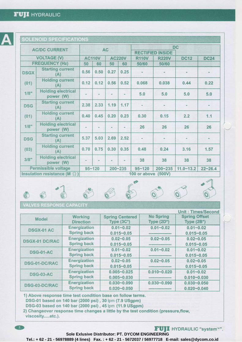
ACIDC CURRENT AC DCffi
VoLTAGE M AC{ 0v AC220V Rl10V R220V nel2 DG24FREQUENCY (Hz) 50 60 s0 t0 50160 50/60
DSGX
{01}
1lg"
Starting current{A}
0.56 0.50 0.27 0.25
flolding current(A) Q.12 0.12 0.56 0.52 0.068 0.038 0.u 0.22
Holding ele*tricalpower {W}
5.0 5.0 5.0 5.0
D$G
t01)
1/8*
$tarting currenttA) 2.38 2.33 1 .19 1 .17
Holding currenttA)
0.40 0.45 0.20 0.23 0.30 0 .15 2.2 1 .1
Holding electricalpower {W}
26 26 2S 26
DSG
(03)
3/8'
$tarting current{A}
5.37 5.03 2.69 2.52
Holding currenttA) 0.70 0.75 0.30 0.35 0.48 0.24 3 .16 1.57
Holding electricalpower {\tY}
38 38 38 38
Permissible voltage 95- 20 209-235 95-120 200-235 11.0-13.2 22*26.4Ineulation resistance tnil A ) 00 orabove {500V)
@
s"& ##&
1) Above response time test condition base on follow terms.DSG-01 based on 140 bar (2000 psi) , 30lpm {7.9 USgpm}DSG-03 based on 140 bar (2000 psi) ,45lpm {11.9 USgpm)
2) Changeover response time changes a little by the test condition {pressure,flow,viscosity.....etc.).
ftilodel WorkingDirection
$pring SenteredType {3C.}
No $pringType {2D"}
$pring OffsetType flB*l
DSGX.0l ACEnergizationSpring back
0.01-0.020.015-0.05
0.0{-0.02 0.01-0.020.015-0.05
D$GX.O1 DC/RACEnergization$pring back
0.02-0.050.015-0.05
0.02*0.05 0.02-0.050.015-0.05
DSG-$1-ACEnergizationSpring back
0.01-0.020.015-0.05
0.01-0.02 0.01-0.020.015-0.05
DSG41.DC/RACEnergization$pring back
0.02-0.050.015-0.05
0.02-0.05 0.02-0.050.015-0.05
D$G-03-ACEnergization$pring back
0.005-0.0250.005-0.030
0.010-0.020 0.01-0.020.010-0.030
nsG-03-DcIRAC EnergizationSpring back
0.030-0.0900.020-0.050
0.030-0.090 0.030*0.0500.020-0.040
FUJI HYDRAULIC "system'""Sole Exlusive Distributor: PT. DYCOM ENGINEERING
Tel.: + 62 - 21 - 56978889 (4 lines) Fax. : + 62 - 21 - 5672037 / 56977718 E-mail: [email protected]

*=5 ; i { iF : : *a !s & ; i ;= : * i i J ; i : * i { i
: i"il*N"f FL*tuVThe high f low rate 63 clnt" (16.6 gpm) of the DSG-(N)-01 valves corresponds to conventional 03 valves.DSG-(N)-03 is capable of control l ing oi l f low up to 120 i l*. , . (31 .7 gpm)DSHG-(N)-04 are capable of control l ing oi l f low up to 300 t lar4.(79.3 1pm)DSHG-(N)-06 are capable of control l ing oi l f low up to 500 t l*a. (132 gpm)And DSHG-(N) -10 are capab le o f con t ro l l ing o i l f low up to 1000 t l * t * , (291 gpm)
IFlow rate is a l i t t le dif ferent between dif ferent spool type.]= i i i G i i - = : - = i r . : ' t - =
The DSG-(N) -01 /03 so leno id va lves , DSHG-(N) -04106/10 Max opera t ing pressure up to 315 bar (4500 PSI ) .il l,-ilMffi #:lfaii,/1fi[: t.1$:sriDurab le L i fe : Durab i l i t y to 50 mi l l ion spoo l sh i f t s . (Average)L i fe Of Sea l ing : No o i l leaks due to use o f no-dynamic sea ls .: : - i iSlt===*i. Gaji=--: ' ; :1i":" i ;3i : . 'nir .- :*= : i l i . fr tr i : :*.Total ly enclosed molded coi l . Special ly treated pressure resistant inner tube(SU5304). High grade steel cored(C2503) coi l withwet solenoid. Al l moving parts are immersed in operating oi l and muff led to provide low noise operation.i: $,ifi [r:i, :-.il,jq$4;$.i:ilSpec ia l des ign o f over - r ide p ins and sea ls p revent o i l leakage.:*- i.,.il!fl''i i:.=ttl;l',fl iJ t.:= -::;rt::;:
See technical data of pressure drop for detai ls. (P-25):. r i 'X1i l i r i : i , , i i l i l { f}{ i i#r!$Ufl$r ,SI- l i l \ r 'wi l" [ . ] in I r : l i f r i { l ; i j1.r; i \ l ; t , . l , . i$The DSG-(N) -01 i03 can be used w i th back pressure up to 160 bars (2300 PSI ) on the tank por t "T" .DSHG-(N) -04106/10 permiss ib le backpressure , in te rna l d ra in 160 bars (2300 PSI ) ,and 210 bar {3000 PSI ) fo r ex te rna l d ra in type . P ipe the re tu rn back to tank be low the o i l leve l .i...1 { f( il I {;r JiT'il iq ["t 1S i"t "i il ii l. fl ]:;1 li ]So leno id ind ica tor l igh ts a re s tandard , a l l DSG-0 '1 /03 { te rmina l box type) , DSG-N-01103 (D lN type) w i th a l l vo l tages , ensur ingeasy tes t ing and main tenance a t a g lance.DIN connector meet CE, lP 65 , DIN 40050, ISO 6952 water p roo f s tandard .(AC: Red led . , DC:Ye l low led . RAC: Green led . )i : i l r i i t -Insu la t ion h igh vo l tage tes t : 1500 V/min . (1800 V/sec . )Doub le insu la t ion w i r ing , hermet ica l l y sea led fo r mo is tu re- res is tance. Insu la t ion c lass : HMax imum a l lowab le co i l tempera ture : + 150C (+300F)Do not exceed permiss ib le vo l tage range o f the co i l used.Do no t supp ly e lec t r i c power to the AC so leno id un less the co i l i s mounted to the va lve .DIN type co i lw i th 360 poss ib le o r ien ta t ion .No-spr ing type (DSHG-2N--04 /06 i 10) one o f the co i l shou ld be energ ized cont inuous ly to avo id mal func t ion .On doub le so leno id va lves , do no t energ ize bo th a t the same t ime as i t w i l l resu l t in co i l s burn ing ou t .l. l-{$.Tffi!{*t1...ffi trdr 3 itt{}tu {fl* 1,fr1Bodies are of high tensi le cast iron with large shel l cored passages. Spool bores are precision honed with accurately machinedland locations.i-j ft p){l 4:1 ri"- iiSpoo ls a re hardened a l loy s tee l (SCM21) , p rec is ion ground and incorpora te ba lanc ing grooves . A l l spoo ls a re in te rchangeab lewi th va lve body s imp l i f y ing main tenance. Many op t ions in spoo l type se lec t ion .= : S f . 4 . = : = . : , * * = , . = = = - l R i t : * - 1 . ' : r , 1 * 1 = a : O l ; : ' a i = = . ; j 3 . = : = i j : C G I : - ! , ' , : L i i i = = = .There are 3 types (DlN, Terminal Box, SWP) for standard electr ical connection and variety of AC,DC & RAC coi l voltages. Coilvoltages. AC:AC 100V/AC11OV/AC200V/AC22OV/AC240V (50/60H2) DC:OC12124136148RAC : RAC 1 00V/AC 1 1 0V/AC 200V I ACzzOV I AC240Vl : l lYS i i==L:L i S+5*= i {LH5= :Y-* i : i : := L i : 'Cr I i i : := t1 1 ' f i :aThe DC/RAC type solenoid valves with a cushion device, results in a smooth com- mutation from a posit ion to another posit ion(smooth start and stop performance). This wil l greatly reduce the noise which comes from changing over and vibrat ing pipes,The op t ionaf s t roke l im i te r (RW/RA/RB) can be 114. ,1 !3 . ,1 /2 mic ro ad jus tments search fo r the bes t so f t smooth cush ion . Whenthe stroke l imiter is screwed in, the main spool stroke becomes shorter and f low rate becomes lower.The max adjustment rangedetai ls as fol low.
DSGX-(N) -01-DC/RAC: max. ' l .4 mmDSG-(N) -01-DC/RAC: max. 1 .4 mmDSG-(N) -03-DC/RAC: max. 2 .2 mmDSHG-(N) -04-AC/DC/RAC: max. 7 mmDSHG-(N) -06-AC/DC/RAC: max. 12 mm
i: fiilH{:iii,,E-. f Vfl[,], iVfii lrfr,{;: f;:ti "i'\Flff y'nli:riii..ili[*,""8(A) Shockless + shif t ing t ime adjustable. (B) Stroke l imiter adjustable.(RA/RB/RW types)(C) Lead w i re type (SWP connector te rmina ls ) fo r mar ine , mob i le par ts .(D) Exp los ion proo f ( f lame proo f ) type . (E) Surge less (Surge K i l le r ) t ype .(F) Sparkless (Spark Ki l ler) type. (G) Water proof type. (H) Vibrat ion proof type.( l ) A C 2 4 . , D C 1 4 . 5 0 . , D C 2 8 . , D C 3 6 . , D C 4 8 . , D C 1 1 0 . . . . . " ( J ) V i t o n s e a l $ w e r e a v a i l a b l e .Consu l t loca l agent fo r de ta i l s .
= .1!t i i :==l ' t i in::=:+i. , ' { ' i :=: ' :The no-spr ing va lves (DSHG-2N-04/06 /10 TYPE) sha l l mounted w i th long i tud ina l ax is hor izon ta l as they work under impu lse .Spr ing centered (3C. ) ,spr ing o f fse t (2B" ) and de ten ted (2D- ) va lves have no or ien ta t ion l im i ta t ion . The DSG-(N) -01 /03 & DSHG-(N) -04106/10 mount ing sur face d imens ions conform to ISO 4401 , Hydrau l i c f lu id power -Four -por t d i rec t iona l con t ro l va lves-Mount ing sur face . The ins ta l la t ion sur face shou ld be f iner than 6 .3 S .= *iji::+:,,.=-4il ij. :::e--::r':.1: -==;Comprehens ive range o f sub-p la tes , mu l t i -s ta t ion man i fo lds and s tackab le modu les .i,..: ffil{'}x;194, rit{;1, ftjI.:r,i^l'l'r r ,,firrll(.;l:li:ilrir-lifriiri';'.Hexagona l socket head cap screw (Met r ic o rAmer ican f i x ing bo l ts ) , and DIN connector + led as s tandard w i th no ex t ra cos t .
FUJI HYDRAULIo "system"" (oSole Exlusive Distributor: PT. DYCOM ENGINEERING
Tel.: + 62 - 21 - 56978889 (4 lines) Fax. : + 62 - 21 - 5672037 / 56977718 E-mail: [email protected]

DIMENSIONS MTLLTMETERS(TNCHES)
. : - l - ] . : : - : ? * ; " ' l * :
4 - 5.5(.22) Dia. Thru9.5(.37) Dia. C'Bore
Pressure Port "P"
Cylinder Port"A
141 .5(5.57)
65(2.56)
l ^
No 5 -
I
T------ --*-----tl ^ r J l ^
f f r I EN Io - l r l
r- L- t- ---)i ' ' , r
Cylinde. Port"B"13 5_
(.53)
Tank Port'T"
-. 40.5 _(1 .5e)
135* - 40.5 _( .53) (1.5e)
27 mpm Connector
:, "; with Indi;tor Light( r . uo )
Lock Nut I
o ,@ o I
-o o
Manual Override
65(2 56)193
(7.60)
48- (1 89)
Mounting Surface(O-Rin9 P9X4pcs)
Coil With 360 Possible Orientation
Attachment Name Description Tiqhteninq Torque Code
Soc. Hd. Cap Screw M5 X45LgX4pcs 5-7 Nm 30Soc. Hd. Cao Screw 10-24UNCX1-3/4"Lox4ocs 43-60 in.lbs 3090
4 - 5.5(.22) Dia. Thru.9.5( .37)Dia. C'Bore
Pressure Port "P"
Cylinder Port"A"
152 .5(6.00)
65(2 56)
t ^q P
o 5I
l ^
nfro 9
I
t ^N
. : :I
Cylindef Port'8"13 .5
( 53)
Tank Port"T"
40.5 _(1.se)
13 5_( 53)
i
40.5(1 .5e )
27 mpm Connector
1''.ouT wth lndi;tor Lishl
Lock Nut
o@ o I
v
Manual Override
65(2.56)215
(8.46)
- 4 8(1 .8e )
Mounting Surface(O-Ring P9X4pcs)
Coil With 360 Possible Orientation
-1I99UreSoc. Hd. Cap $crew M5 X45LgX4pcs 5-7 Nm 30Soc. Hd. Cap Screw 10-24UNCX1-3/4"LeX4pcs 43-60 in.lbs 3090
lD FU|I HYDRAULIG "system""Sole Exlusive Distributor: PT. DYCOM ENGINEERING
Tel.: + 62 - 21 - 56978889 (4 lines) Fax. : + 62 - 21 - 5672037 / 56977718 E-mail: [email protected]

D IMENSIONS MTLLTMETERS( INCHES)
4 - 5.5\ .221 Dia. ThruI 5( .37) Dia. C'Bore
Pressure Port ' 'P"
Cylinder Port"A
I ^q KNo =
I
l ^ I ^- 3 i : 3
o -t * f -
iN̂
- N
t
CvLlnder Por t "B"
(Tank Port"T"
i1 3 . 5 | 4 0 5
i r rgr-
Elec t r i ca l Condu i t Connect lon
G 1 1 2 T h d \ B o r n E n d )
53j (1 ss)
s0(3 54)
( 53)
Lock FJut
lvlairlalOvelllde
65(2 56)
1 93(7 60)
A O \
lvlountrng Surface(O-Rlng PgX4pcs)
C o i l
Attachment Name I Oescription I Tightening Torque ' Code
$oc Hd, C.qn !91ew . N45 X45LgX4pcs 5-7 Nm 30
Soc. Hd. Cap Screw I lO-zqut ' tCx1 3/4"Lgx4pcs 43-60 in. lbs 3090
4 - 5 5\ :22) Dia. Thru9 5( 37) Dia. C'Bore
Pressure Port "P"
Cylrnder Port''A"
152 5!6 00)
65(2 s6)
l ^t": N
' I 6 i
f -
Cvl inder Port"B"! .
13 5 40 5> - _ 4 _ _
_ ( 53) {1 5s)
r f a 1 n A
/ 6 ? \ 1 1 6 0 \
q n / ? 5 d \ Elec t r i ca l Condu i t Connect ion
G1/? Thd ( Both End )
€o f
o ld aO O
:o
t l
lvlanual Override
48(1 89)
cglr
Attachment Name Descraption : Tightening Torque
s9.: .t-r9r clp, Sglgy , J'r5 x45Lgx4p9s s-7 NrnSoc. Hd. Capsctew 10-24UNCX1-3/4"Lgx4pcs 43'60 in ibs
FUJI HYDRAULIo "system'*"(D
Sole Exlusive Distributor: PT. DYCOM ENGINEERINGTel.: + 62 - 21 - 56978889 (4 lines) Fax. : + 62 - 21 - 5672037 / 56977718 E-mail: [email protected]

DIMENSION$ MTLLTMETERS(TNCHES)
4 - 6.5(.26) Dia, Thru
11(.37) Dia. SpotfaceTank Port "T"
(ot
^ l
-Y l
Cylinder Port "B" -54(2.13)-.
92(3.62)
Cylinder Port "A"
Pressure Port "P"_54(2.13)
175.5(6 .91)
-27* mPm Connecior(1.0s) With Indicator Light
Lock Nut
$o ) l;O
f)0
f l
234(9 21) 70(2 76)Manual Override
Mounting Surface coilwnr, 360' Possible orientation
{O-Ring P12xspcs)
Attachment Name Sescription Tightening Torque CodeSoo" Hd. Cap Screw M6 X3SLgX4pcs 12-15 Nm 30Soc. Hd. Cas Screw 114-20UNCX1- tOS-tSO in.tus 3090
4 - 6.5(.26) Dia. Thru
11(.37) Dia. SpotfaceTank Port'T"
^l a' ^l6 9 6- \ : *= c o =$ t : + t
Cylinder Port "8" -54(2.13)
e2(3.62)
Cylind€r P0rt "A"
Pressure Port "P"
54(2"13)_
201(7 .e1)
2T mPm Connector
ii.od With Indicatot Light
Lock Nut
g ) l
o - 1
n
70(2 76)Manual Override
Mouniing Surface
(O-Ring P'12Xspcs)
coitwitl-soo Possibleorientation
Attachment Name Description Tightening Torqile Code$oc. Hd. Cap $crew M6 X35LgX4pcs 12-15 Nm 30
Soc. Hd. Cap Screw 1/4-20UNCX1-1/2'LgX4pcs 105-130 in.lbs 3090
285(11 22)
(D FUII HYDRAULIo "system'""Sole Exlusive Distributor: PT. DYCOM ENGINEERING
Tel.: + 62 - 21 - 56978889 (4 lines) Fax. : + 62 - 21 - 5672037 / 56977718 E-mail: [email protected]
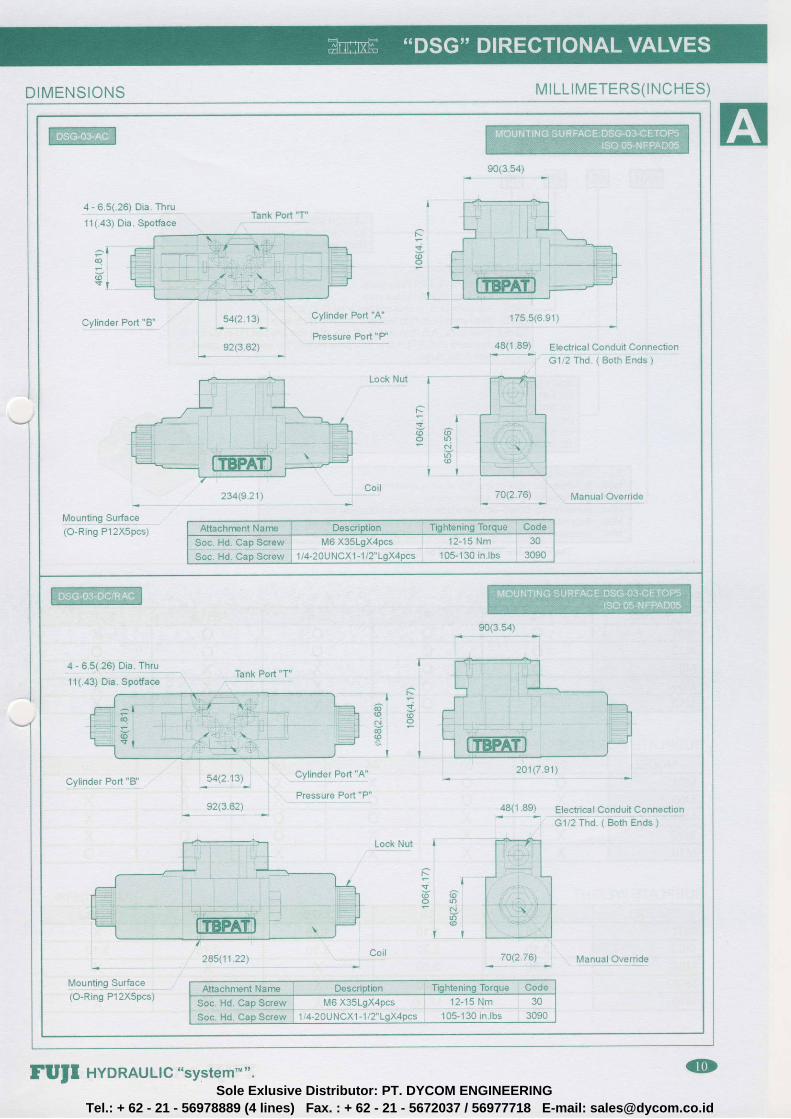
D IMEN S IONS MILL IMETERS( INCHES)
90(3 54)
4 - 615(126) Dia Thq
11(.43) Dia. SpotfaceTank Port "T"
^ loq
6s t
r$(oO
Cyl inder Pod "B"cylildei Port I'A'
Pressure Port "P"
175 .5 (6 .91 ) ;
48(1 .89) Electrical Conduit ConnecttonG1 2 Thd 1 Both Ends )
Lock Nut
Nr iv( o ( oO U ?
6@
t r
Mounting Sur{aJ(O-Ring P12X5pcs)
234(9 21) 7O(2.76) Manual Overr ide
Attachment Name I Description I Tightening Torque Code
$oc. Hd. Cap Screw i wt6 X3SLgX4pcs 12-15 Nm 30
Soc . Hd . CapSc rew j 114 -20UNCX1-1 / s 105-130 in. lbs 3090
90(3:s4)
4 - 6 5(126) Dla Thlu
11(.43) Dia. Spotfacel f
6 6N O
@(o$
l t
Cyl inder Pod "B' -54(2.13)_
92(3.62)
cyllnder Port llAl
Pressure Port "P"Electr ical Condui t Connect ionc112 Thcl . t eoth Endi j
48(1 8e)
Lock Nut i
t'--
( o ( oO I { ). N
Lr)
285(11 22)
H,,touning su*ac"(O-Ring P12X5pcs)
2O1(7 91 )
Attachment l,{arne Description r Tightening Torque ' Code
So9 Hd. cap s91-glirSoc. Hd. Cap Screw
M6 X35LgX4pcs 12-15 Nm 30'1 /4-20U NCXl -112"LgX4pcs 105-130 in. lbs 3090
70{2 76) Manual Overr ide
FUJI HYDRAULIc "system"". (DSole Exlusive Distributor: PT. DYCOM ENGINEERING
Tel.: + 62 - 21 - 56978889 (4 lines) Fax. : + 62 - 21 - 5672037 / 56977718 E-mail: [email protected]

SERIES NUMBERM01: Subplatas for D$G-01 and D$GX-0{ solenoid valvesM03: $ubplates for DSG43 eol*noid valvssM04; $ubplates for 0$HG-04 $olenoid contfolled pilot ope€ted valvesM06: Subplates *cr SSHG-0S solenoid contfolled pilot operated valve$M10: Subplates tor D$HG-06 solenoid controlled pilot operated valves
PORT SIZE02:.114'03;3/8'M:712 'S6;314"10:1-114"
45: four potts {A,B,P.T} side ports48: four ports (A,B,RT) back ports2$28: two ports (A,B) in side and two ports (P,T) in back3$18: three port* (4,8,P) in side and ons port (T) in ba*3$182: three ports tA,8,p) in side {A+B on6 sid€) snd one port (f) in back4$48: faur pons (A,B,P,T) in side ,four ports (A,B,flT) in baek and supplied
PESIGN NO3S: with FTthread3090: with NPT thresd
The installation surfacs should be finer than
ii, i-.ri#r r*,'\T il fp#ilqT F'#s 1-l I i: l';MODEL 4$ 4B 2$28 3S1B 3S182
M01 o o o o XM03 o O o o oM04 o o X X XM06 o o X X XM 1 0 X o X X X
lli-j iliFr1.",,rif il ff {.}irtl" ii ;;:ii
MODFL 02 03 04 06 08 10M01 o o X X X XM03 X o o X X XM04 X X o o X XM06 X X X o o XM 1 0 X X X X X o
1-Jnif: +tp*iprr
MODEL 4S 4.8 2$28 3S1fi 3S182M01 1 . 1 0 1 . 1 0 1 . 1 0 1 . 1 0 XM03 3 . 1 0 2"20 J . I U 3 " 1 0 3 . 1 0M04 4.80 3.00 X X XM06 9.50 4.60 X X XM 1 0 X 17.00 X X X
fUJI HYDRAULIo "system'""Sole Exlusive Distributor: PT. DYCOM ENGINEERING
Tel.: + 62 - 21 - 56978889 (4 lines) Fax. : + 62 - 21 - 5672037 / 56977718 E-mail: [email protected]

SUBPLATE D lM EN S IONS:M ILL IM ETE RS( INCH ES)
_ 4 0 . 5 ( 1 . 5 9 ) 1 4 2' ( .56)
3 0 . 2 ( 1 . 1 9 )
2 1 . 5-t.aoi
{ 5oi-
4 - C T h d- ? o - D T h d
( . 7 e )4 - 6(.24, Dia.
I E T h d
II
- € - f l= a N
' :-
a o L
rI
l ^q RN j
, - l -- ' = i i S
c r a o i : f i < i j to l & c i b N = : 9
Y : l - I " l *I
i ^ ro o
6.1:di
€ 't^ <2
- J N I
I
N
7 1 ( 2 . 8 0 )
8 5 ( 3 . 3 5 )
l
7( . 2 8 )
4 - 7 ( .28) O ia . Thru
11( .43) D ia . Spot face
l ^
t *
( 4 e )3 5 . 5 i 1 . 4 0 )
s8 .5(2 .30)E Thd
- 4 2 . 5 ( 1 . 6 7 ) _
coDE cThd. D Thd. E Thd
M01-02- " -30 M5XP0.8 Pr1 t4 PT1t4
1 ,401-02- - - -3090 10-24UNC t ' tp r t la NPTl /4
M01-03- - ' -30 M5XP0.8 PT3/8 PT3/B
M01-0C-- - -3090 10-24uNC Npr3 /B r ' rp rs la
4 - 1 1 ( . 4 3 ) D i a .
- 50 .8(2 .00)
_
3 7 . 3 ( 1 . 4 7 )
2 7 ( 1 . 0 6 )
1 6 . 7( .66) i
4 - C T h d
i
D Thd
^ tf P ^
6 - - o -o * : t 6 - l ;-
| ' - r - : 1 9
I
: 3 0
IC i
N ! r
i N
Gj 6' !ax @ Y
N$
l r
I
l l J
54\2.13)
90{3 .54 )
1 1 0 ( 4 . 3 3 )
j 1 8 ,( . 7 1 )
I
4 - 9 ( ,35) D ia . Thru
141.55) Oia. Spotface20-(.7et
4 0 ( 1 . 5 7 )2 8 ( 1 . 1 0 )
- . s0(1 .97)
_
- 74 t2 .91)
E T h d .
I
t ^ -. \
! - I
CODF C Thd, D Thd. E Thd. F
M03-03- . . -30 M6XP1.0 PT3/8 PT3/B 30(1 .18)
M03-03- - . -3090 1 /4-20UNC NPT3/8 NPT3/8 30(1 .18)
M 0 3 - 0 4 - - . - 3 0 r M O X P ' 1 . 0 P T 1 1 2 P T 1 / 2 3 0 ( 1 . 1 8 )
M03-04- - " -3090 1 /4-20UNC NPTl /2 NPTl /2 30(1 .18)
" F " i s fo r por t pos i t ion " 4B " type on ly .
FUJI HYDRAULIC "system'"" lDSole Exlusive Distributor: PT. DYCOM ENGINEERING
Tel.: + 62 - 21 - 56978889 (4 lines) Fax. : + 62 - 21 - 5672037 / 56977718 E-mail: [email protected]

DESIGN NO30: with PT thread
NUMBER OF STATION$13: 1 $tation25 : 2 $iations35 : 3 $iations45 :4 Stations$$ : 5 $tations6S :6 Statisns7S : 7 StationsBS : I $tations95 ; 0 Stations
$HRIFS NUMtsERMM01r Manifolds for D$G-01 and D$GX^01 solenoid valve$MM03: Manifolds for DSG43 $olenoid valves
t . i , j . , " . ' i . , r ' . , 1; t : .
: ' " . ;
1. The installation surface should be finer than ffi2. Material:Casting iron FC 30 ( or steel or aluminium )3. Max Working Pressure: 315 bar
T-1- - * --i
I l-" -i - i- -i-l
(P) ' i i ,1 , i i , i t ' . i iPl , ; i i '
r l . i ' ) i j , l . r tL- - - - - iL - - - - - - l
B A B A
fUfI HYDRAULIC "system""Sole Exlusive Distributor: PT. DYCOM ENGINEERING
Tel.: + 62 - 21 - 56978889 (4 lines) Fax. : + 62 - 21 - 5672037 / 56977718 E-mail: [email protected]

ffiTank Port "T'
D Thd.
T--';*-ll r {
l '-,-.1t ll ' r l
Cylinder Port "A"
E Thd.
4 - 7(.28) Dia.
c rhd
31(1.U) 14.s(.57)
1o!l:19
I
q
- ti
ts
-20-(.7e)
Cylindor Pod "B''E Thd-
23 1< l
i .e1) l63(2.48) l
80(3.1 5)
42.5I 1r.oz1
-
o X 42.5(1.67j32.5
: l : f 2 - ss i . z2 )D ia l h ruoutz .sJ* 10{.39) Dia. C'Bore
6(.24) nep
Pressure Port "P"
D Thd.
( P ) . I P/ T \| \ , /
in
I
I
CODE cThd. , DThd. EThd.
MM01-1S-30 M5XP0.8 PT3/8 PT'UZ
MM01-15-3090 10-24UNC NPT3/B NPTl/2
Cylinder Pin "A"E Thd.Each Station
4 - Port HolesEach Sfation
40.5(1.59)4 - C T h d .Each Station
Tank P{n'f
D Thd.
Cylinder Port'B'E Thd.Each Station
^ lNg?5o 1 4s r q : 3
, i N -
h t -
* r <v
^ l iFq
i ^ 5
o J I
t1
Fq a
P XS i
t 4
i I
$ s !
I
PHsure Port "P"
D Thd.
Tank Pofi "T.D Thd,
* 15__(.5e)
_ 3 0 _(1.18) 2 - 9(.35) Dia. Thru
- 60(236)
- i4 { .sb)o ia .c Bore14(.55) Deep
Pressure Port'P"
D Thd.
Tank Poil "T"
D Thd,
50(1 .97)
35(1.3S)
^ i
- q
4" o l *t I + .
I
c Thd. DThd. EThd. F N L
PT3l8 PTll2 50 . 130NFT3/B NpT,1/2 (1.97) '
1s.tt1
PT3/8 PT1l2 100 I 180
NPTS/B NpT1l2 (3 %) ' 1z.oe;
PT3/B PT\A 150 230r.rprere Niive {5.91) 4 (9.00)
PT3/E Prltz zoo ^ iaoNP-r3r8 NPrll2 (7 87) " (1]:021
FT3/8 PT1lz 250 A 330NPT3/B NpTl/2 (9.&4) " 1tz.ss;
PT3/8 PT1l2 300 7 380r ' rp is la NpTt/z (11.s1) '
1t+.eo;
MANIFOLDS DIMTNSION$:MILLIMETERS(INCHES)
FUJI HYDRAULIc "system''"" (!)Sole Exlusive Distributor: PT. DYCOM ENGINEERING
Tel.: + 62 - 21 - 56978889 (4 lines) Fax. : + 62 - 21 - 5672037 / 56977718 E-mail: [email protected]

MANIFOLDS DIMENSIONS: M ILLIMETERS(INCHES)
P r e s s u r e P o n " P "
D T h d ,
Tank Port "T"
D T h d .
I
, r 4 , 1 0 ( . 3 9 )
4 - C T h d4 6 ( 1 8 1 ) i 7
{ . 6 7 )
P r e s s u r e P o r t - P '
D T h d
^ ^ l
' tN l :
' l *
C y l i n d e r P o r t ' A "
D T h d .
Cyl inder Poft "8"D Thd
l 6I
4 B ( 1 . 8 9 )
T A A P B
- 3 2 -(1 26)
60(2 .36) *
- 6412 52)
8 0 ( 3 . 1 s )
8
{ . 3 1 ) 4 - 7 1 . 2 8 ) D i a . T h r u
1 0 1 . 3 9 ) D i a . C ' B o f €6 . 5 ( 2 6 ) D e e p
T
( P )
( r )Y
c o D E c T h d . D T h d .
MM03,1S-- . -30 M6XP0.8 PT3/8
MM03-15 - ' - - 3090 1 /4 -20UNC r . r p r3 l 8
[T-TTI] C y l i n d e r P o r t ' A " C y l i n d e r P o r l ' 8 "
E a c h S t a t i o n E a c h S l a t i o nD T h d D T h d
54(2 .1 3 l4 - Pod Ho les
Each Sta t ion
4 - C T h d .
E a c h S t a t i o n
_ l a l ri t 5
i ^I
a Po 6
I
t
Pf€ssure Port "P"
r D l h d .
5 :
I
Tank Port "T'
D T h d .
I
!
I
' t 5-i set
- 5 0 ( 1 9 7 )
8 2 1 3 . 2 3 1
1 6
{ . 6 3 )
j 6 (1 42J 4 , s ( .35) D ia . Thru14( 55) D ia . C 'Bore
9 0 1 3 5 4 ) 1 ? / d 7 \ n F a r ,
3 5 ( 1 . 3 8 )
P r e s s u r e P o d " P "
D T h d
Tank Port "T"
D Thd
r - 6
P
( r )( P )
T .t 2 7 6 )
4 1- ( 2 . 7 6 )
6 2
A B A B
CODE C Thd . D Thd . LMM03-2S-30
MM03-2S-3090MM03-3S-30
MM03-3S-3090Mf,,1OS- S-eO
MM0345-3090MM03-SS-30
MM03-55-3090MM03-6S-30
MM03-65-3090
M 6 X P 1 . 0 P 7 1 1 2 1 6 01 /4 -20UNC NPT l / 2 ( 6 .30 )
M 6 X P 1 . 0 P r 1 1 2 2 3 S1 /4 -2ouNC NPT l / , ( 9 . 25 )
M 6 X P 1 . 0 P I 1 1 2 3 1 01 /4 -20UNC xp1112 (12 .20 )
M6XP1 .0 PT1 l2 3Ss1 / 4 - 2 0 U N C N p r y Z ( 1 5 . 1 6 )
M6XP1 .0 PT112 4601 / 4 - 2 0 U N C N P T l 1 2 ( 1 8 . 1 1 )
(D fUJI HYDRAULIC "system'u"Sole Exlusive Distributor: PT. DYCOM ENGINEERING
Tel.: + 62 - 21 - 56978889 (4 lines) Fax. : + 62 - 21 - 5672037 / 56977718 E-mail: [email protected]