Embed Size (px)
Citation preview
Kennedy Valve/UL/FM Butterfly Valves 11-1
11-2 Kennedy Valve/UL/FM Butterfly Valves
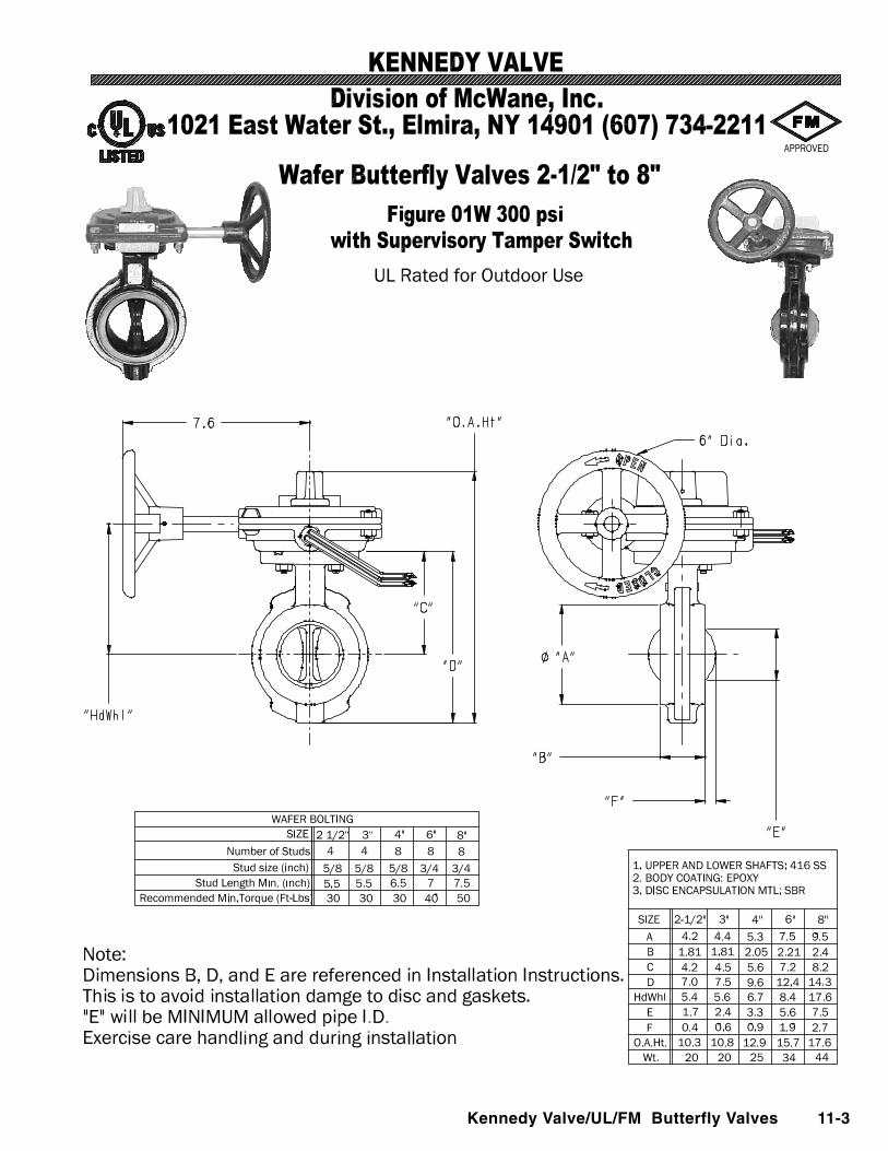
Kennedy Valve/UL/FM Butterfly Valves 11-3
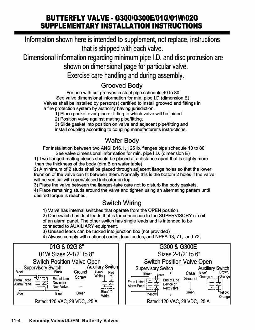
11-4 Kennedy Valve/UL/FM Butterfly Valves
Kennedy Valve / Check Valves 15-1
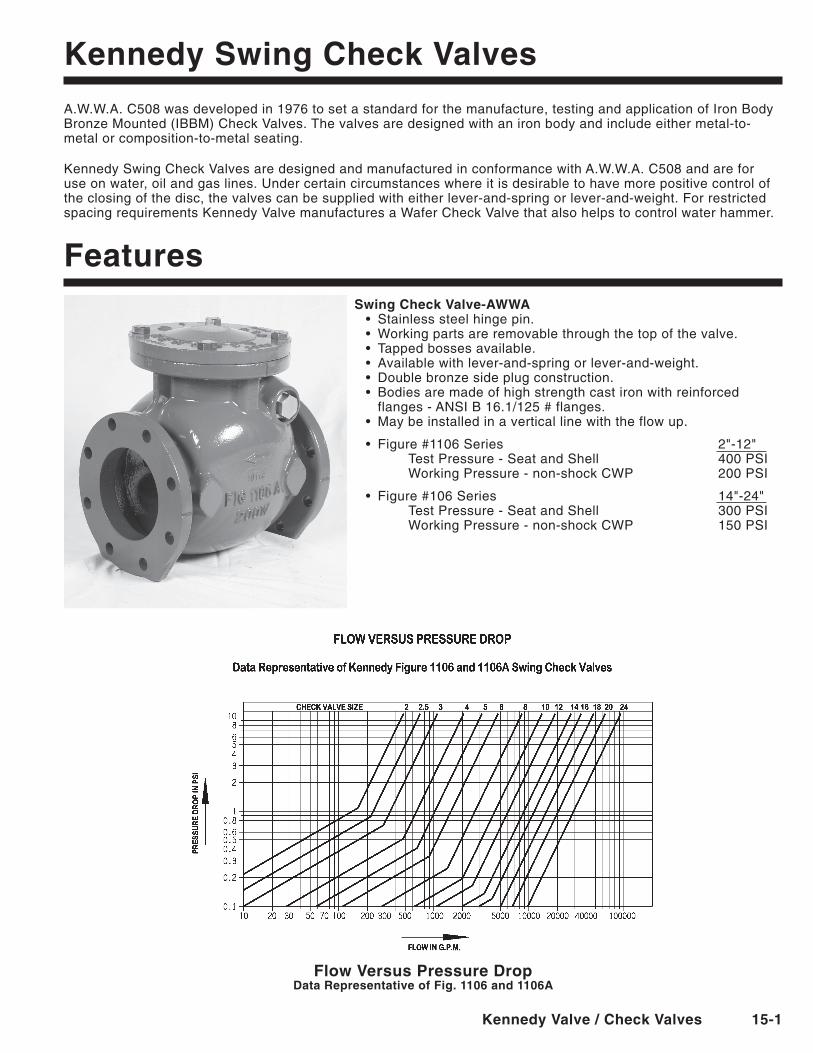
Kennedy Swing Check Valves
A.W.W.A. C508 was developed in 1976 to set a standard for the manufacture, testing and application of Iron Body Bronze Mounted (IBBM) Check Valves. The valves are designed with an iron body and include either metal-to-metal or composition-to-metal seating.
Kennedy Swing Check Valves are designed and manufactured in conformance with A.W.W.A. C508 and are for use on water, oil and gas lines. Under certain circumstances where it is desirable to have more positive control of the closing of the disc, the valves can be supplied with either lever-and-spring or lever-and-weight. For restricted spacing requirements Kennedy Valve manufactures a Wafer Check Valve that also helps to control water hammer.
FeaturesSwing Check Valve-AWWA• Stainlesssteelhingepin.• Workingpartsareremovablethroughthetopofthevalve.• Tappedbossesavailable.• Availablewithlever-and-springorlever-and-weight.• Doublebronzesideplugconstruction.• Bodiesaremadeofhighstrengthcastironwithreinforced
flanges - ANSI B 16.1/125 # flanges.• Maybeinstalledinaverticallinewiththeflowup.
• Figure#1106Series 2"-12" Test Pressure - Seat and Shell 400 PSI Working Pressure - non-shock CWP 200 PSI
• Figure#106Series 14"-24" Test Pressure - Seat and Shell 300 PSI Working Pressure - non-shock CWP 150 PSI
Flow Versus Pressure DropData Representative of Fig. 1106 and 1106A
15-2 Kennedy Valve / Check Valves
KenneDy CheCK VAlVeS
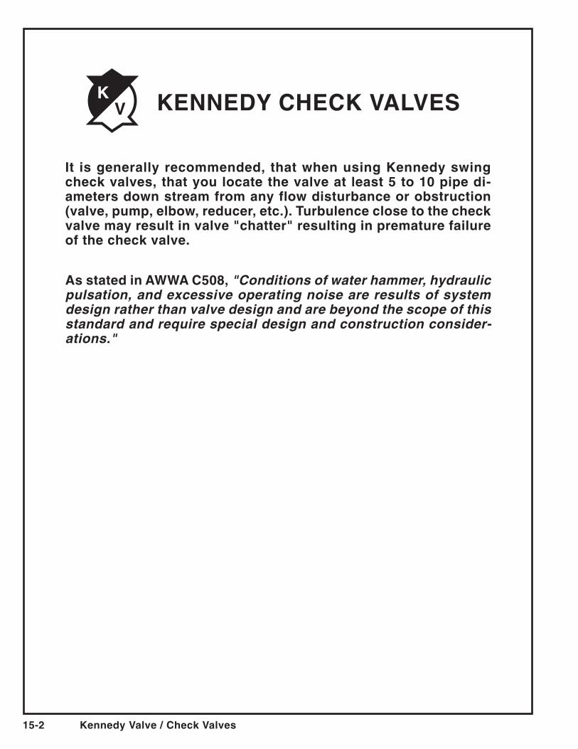
It is generally recommended, that when using Kennedy swing check valves, that you locate the valve at least 5 to 10 pipe di-ameters down stream from any flow disturbance or obstruction (valve, pump, elbow, reducer, etc.). Turbulence close to the check valve may result in valve "chatter" resulting in premature failure of the check valve.
As stated in AWWA C508, "Conditions of water hammer, hydraulic pulsation, and excessive operating noise are results of system design rather than valve design and are beyond the scope of this standard and require special design and construction consider-ations."
Kennedy Valve / Check Valves 15-3
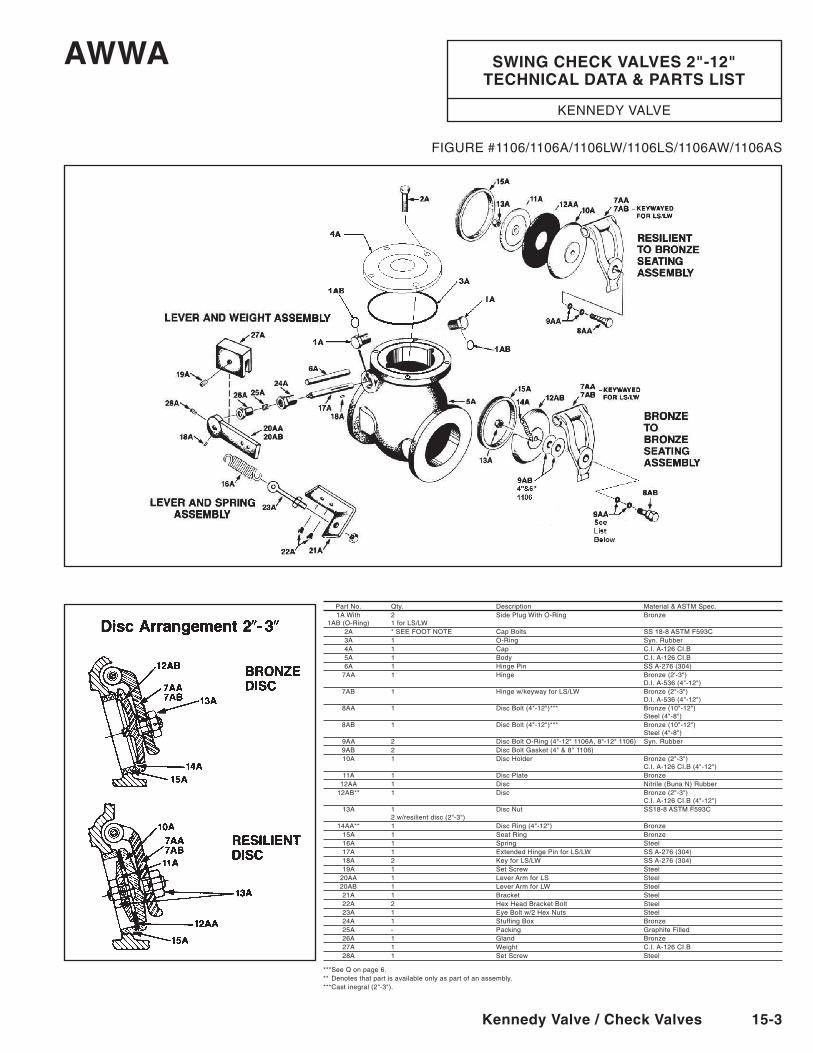
PartNo. Qty. Description Material&ASTMSpec. 1A With 2 Side Plug With O-Ring Bronze 1AB (O-Ring) 1 for LS/LW 2A * SEE FOOT NOTE Cap Bolts SS 18-8 ASTM F593C 3A 1 O-Ring Syn. Rubber 4A 1 Cap C.I. A-126 CI.B 5A 1 Body C.I. A-126 CI.B 6A 1 Hinge Pin SS A-276 (304) 7AA 1 Hinge Bronze(2'-3") D.I.A-536(4"-12") 7AB 1 Hingew/keywayforLS/LW Bronze(2"-3") D.I.A-536(4"-12") 8AA 1 DiscBolt(4"-12")*** Bronze(10"-12") Steel(4"-8") 8AB 1 DiscBolt(4"-12")*** Bronze(10"-12") Steel(4"-8") 9AA 2 DiscBoltO-Ring(4"-12"1106A,8"-12"1106) Syn.Rubber 9AB 2 DiscBoltGasket(4"&8"1106) 10A 1 DiscHolder Bronze(2"-3") C.I.A-126CI.B(4"-12") 11A 1 DiscPlate Bronze 12AA 1 Disc Nitrile(BunaN)Rubber 12AB** 1 Disc Bronze(2"-3") C.I.A-126CI.B(4"-12") 13A 1 DiscNut SS18-8ASTMF593C 2w/resilientdisc(2"-3") 14AA** 1 DiscRing(4"-12") Bronze 15A 1 Seat Ring Bronze 16A 1 Spring Steel 17A 1 Extended Hinge Pin for LS/LW SS A-276 (304) 18A 2 Key for LS/LW SS A-276 (304) 19A 1 Set Screw Steel 20AA 1 Lever Arm for LS Steel 20AB 1 Lever Arm for LW Steel 21A 1 Bracket Steel 22A 2 Hex Head Bracket Bolt Steel 23A 1 Eye Bolt w/2 Hex Nuts Steel 24A 1 Stuffing Box Bronze 25A - Packing GraphiteFilled 26A 1 Gland Bronze 27A 1 Weight C.I. A-126 CI.B 28A 1 Set Screw Steel
* **See Q on page 6.** *Denotesthatpartisavailableonlyaspartofanassembly.***Castinegral(2"-3").
AWWA SWInG CheCK VAlVeS 2"-12" TeChnICAl DATA & PARTS lIST
KENNEDYVALVE
FIGURE#1106/1106A/1106LW/1106LS/1106AW/1106AS
15-4 Kennedy Valve / Check Valves
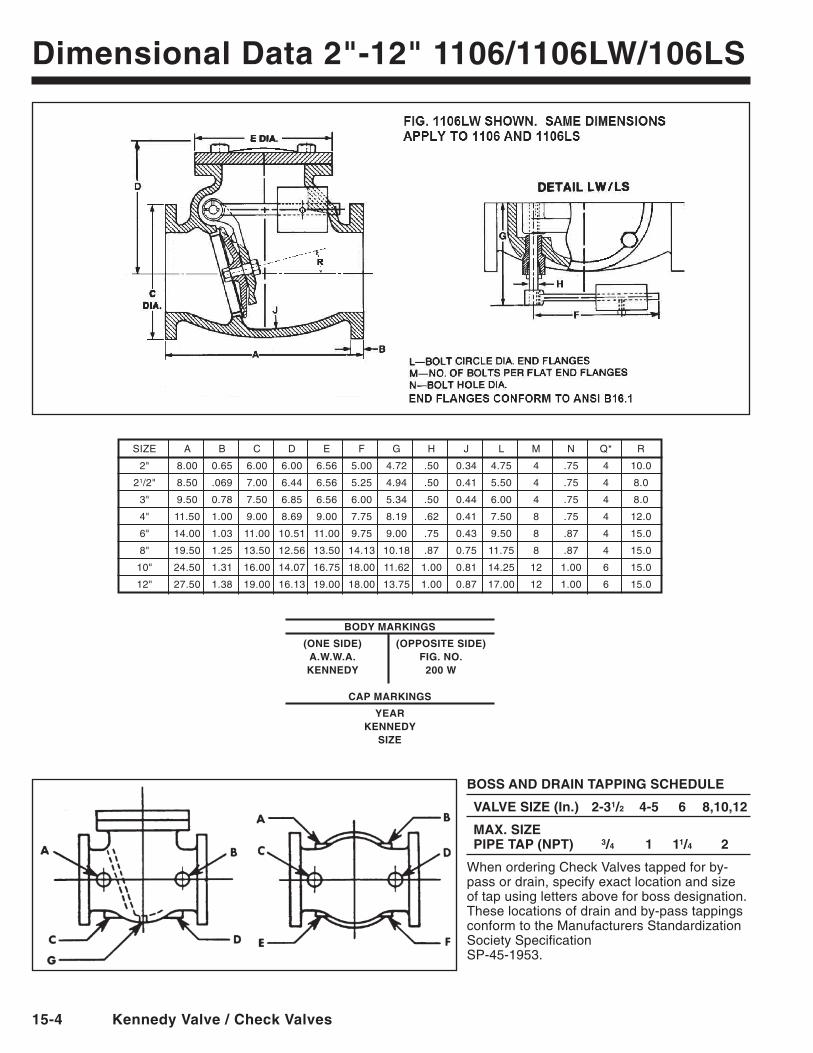
Dimensional Data 2"-12" 1106/1106lW/106lS
BOSS AnD DRAIn TAPPInG SCheDUle
VAlVe SIZe (In.) 2-31/2 4-5 6 8,10,12
MAX. SIZe PIPe TAP (nPT) 3/4 1 11/4 2
When ordering Check Valves tapped for by-pass or drain, specify exact location and size of tap using letters above for boss designation. These locations of drain and by-pass tappings conform to the Manufacturers Standardization Society Specification SP-45-1953.
BODy MARKInGS
(One SIDe) (OPPOSITe SIDe) A.W.W.A. FIG. nO. KenneDy 200 W
CAP MARKInGS
yeARKenneDy
SIZe
SIZE A B C D E F G H J L M N Q* R
2" 8.00 0.65 6.00 6.00 6.56 5.00 4.72 .50 0.34 4.75 4 .75 4 10.0
21/2" 8.50 .069 7.00 6.44 6.56 5.25 4.94 .50 0.41 5.50 4 .75 4 8.0
3" 9.50 0.78 7.50 6.85 6.56 6.00 5.34 .50 0.44 6.00 4 .75 4 8.0
4" 11.50 1.00 9.00 8.69 9.00 7.75 8.19 .62 0.41 7.50 8 .75 4 12.0
6" 14.00 1.03 11.00 10.51 11.00 9.75 9.00 .75 0.43 9.50 8 .87 4 15.0
8" 19.50 1.25 13.50 12.56 13.50 14.13 10.18 .87 0.75 11.75 8 .87 4 15.0
10" 24.50 1.31 16.00 14.07 16.75 18.00 11.62 1.00 0.81 14.25 12 1.00 6 15.0
12" 27.50 1.38 19.00 16.13 19.00 18.00 13.75 1.00 0.87 17.00 12 1.00 6 15.0
Kennedy Valve / Check Valves 15-5
DRAW
N BY
CHEC
KED
APPR
oVED
DATE
SCAL
E
DWG
No.
REV.
Kenn
edy
Valv
e
14" S
WIN
G C
HEC
K VA
LVE-
RU
BBER
FAC
ED-
FLAN
GED
EN
D
KM
2/
28/7
4
No
NE
11
802
SP
RIn
G A
nD
le
Ve
R C
he
CK
V
AlV
eS
Ty
le
nO
. 25
9-02
/106
Al
S
le
Ve
R A
nD
We
IGh
T C
he
CK
V
AlV
eS
Ty
le
nO
. 15
9-02
/106
AlW
FP
lA
In C
he
CK
VA
lVe
14"
ST
yl
e n
O.
59-0
2/10
6A
21
011
14 9 8 3 12 4 22
13
23 1
7255
15
21
16
18
17
21
19
2026
PAR
T N
O.
A.S.
T.M
.
NO
. R
EQ’D
PA
RT
MAT
ERIA
L SP
EC.
NO
.
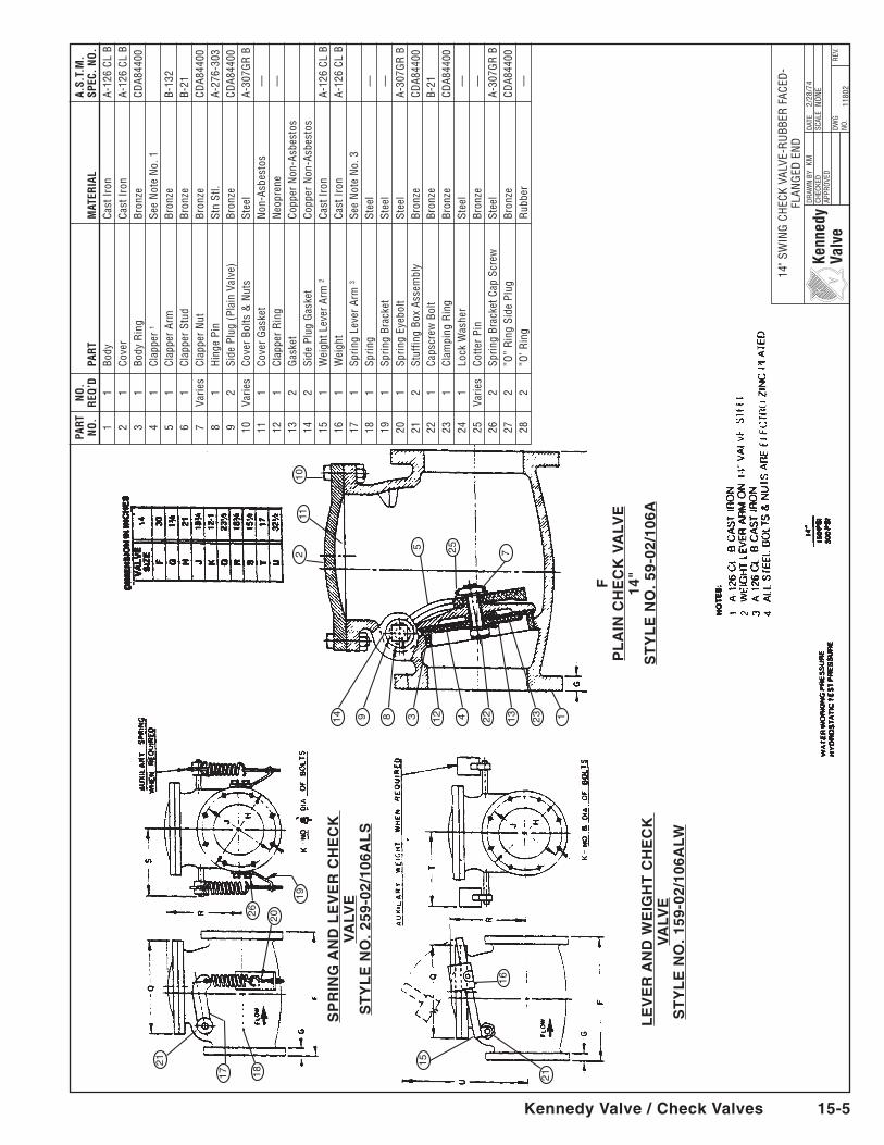
1 1
Body
Ca
st Ir
on
A-12
6 CL
B
2 1
Cove
r Ca
st Ir
on
A-12
6 CL
B
3 1
Body
Rin
g Br
onze
CD
A844
00
4 1
Clap
per
1 Se
e N
ote
No.
1
5 1
Clap
per
Arm
Br
onze
B-
132
6
1 Cl
appe
r St
ud
Bron
ze
B-21
7
Varie
s Cl
appe
r N
ut
Bron
ze
CDA8
4400
8
1 H
inge
Pin
St
n St
l. A-
276-
303
9
2 Si
de P
lug
(Pla
in V
alve
) Br
onze
CD
A844
00
10
Varie
s Co
ver
Bolts
& N
uts
Stee
l A-
307G
R B
11
1
Cove
r G
aske
t N
on-A
sbes
tos
—
12
1
Clap
per
Rin
g N
eopr
ene
—
13
2
Gas
ket
Copp
er N
on-A
sbes
tos
14
2
Side
Plu
g G
aske
t Co
pper
Non
-Asb
esto
s
15
1 W
eigh
t Lev
er A
rm 2
Cast
Iron
A-
126
CL B
16
1
Wei
ght
Cast
Iron
A-
126
CL B
17
1
Sprin
g Le
ver
Arm
3 Se
e N
ote
No.
3
18
1 Sp
ring
Stee
l
—
19
1 Sp
ring
Brac
ket
Stee
l
—
20
1 Sp
ring
Eyeb
olt
Stee
l A-
307G
R B
21
2
Stuf
fing
Box
Asse
mbl
y Br
onze
CD
A844
00
22
1 Ca
pscr
ew B
olt
Bron
ze
B-21
23
1
Clam
ping
Rin
g Br
onze
CD
A844
00
24
1 Lo
ck W
ashe
r St
eel
—
25
Va
ries
Cotte
r Pi
n Br
onze
—
26
2 Sp
ring
Brac
ket C
ap S
crew
St
eel
A-30
7GR
B
27
2 ”o
” R
ing
Side
Plu
g Br
onze
CD
A844
00
28
2 ”o
’ Rin
g
Rub
ber
—
15-6 Kennedy Valve / Check Valves
DRAW
N BY
CHEC
KED
APPR
oVED
DATE
SCAL
E
DWG
No.
REV.
Kenn
edy
Valv
e
16"-
30" S
WIN
G C
HEC
K VA
LVE-
RU
BBER
FAC
ED-
FLAN
GED
EN
D
KM
10
-22-
73
No
NE
11
804
PAR
T N
O.
A.S.
T.M
.
NO
. R
EQ’D
PA
RT
MAT
ERIA
L SP
EC.
NO
.
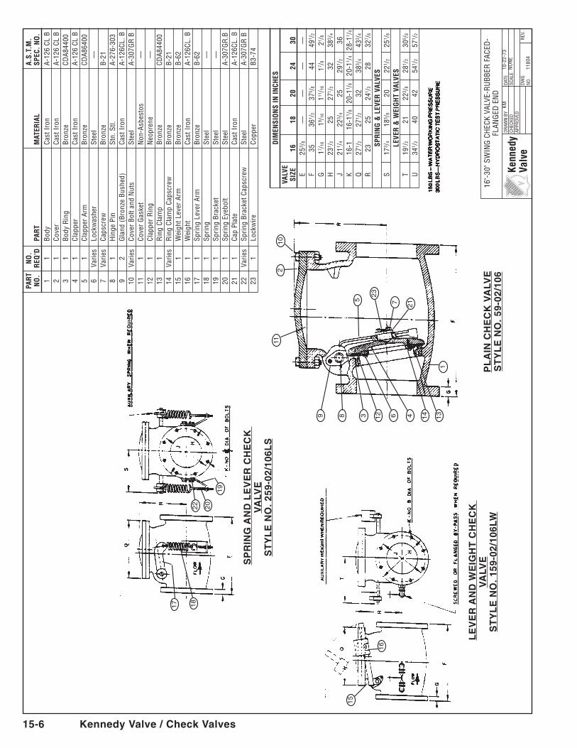
1 1
Body
Ca
st Ir
on
A-12
6 CL
B
2 1
Cove
r Ca
st Ir
on
A-12
6 CL
B
3 1
Body
Rin
g Br
onze
CD
A844
00
4 1
Clap
per
Cast
Iron
A-
126
CL B
5
1 Cl
appe
r Ar
m
Bron
ze
CDA8
6400
6
Varie
s Lo
ckw
ashe
r St
eel
—
7
Varie
s Ca
pscr
ew
Bron
ze
B-21
8
1 H
inge
Pin
St
n. S
tl.
A-27
6-30
3
9 2
Gla
nd (
Bron
ze B
ushe
d)
Cast
Iron
A-
126C
L. B
10
Va
ries
Cove
r Bo
lt an
d N
uts
Stee
l A-
307G
R B
11
1
Cove
r G
aske
t N
on-A
sbes
tos
—
12
1
Clap
per
Rin
g N
eopr
ene
—
13
1
Rin
g Cl
amp
Bron
ze
CDA8
4400
14
Va
ries
Rin
g Cl
amp
Caps
crew
Br
onze
B-
21
15
1 W
eigh
t Lev
er A
rm
Bron
ze
B-62
16
1
Wei
ght
Cast
Iron
A-
126C
L. B
17
1
Sprin
g Le
ver
Arm
Br
onze
B-
62
18
1 Sp
ring
Stee
l
—
19
1 Sp
ring
Brac
ket
Stee
l
—
20
1 Sp
ring
Eyeb
olt
Stee
l A-
307G
R.B
21
1
Cap
Plat
e Ca
st Ir
on
A-12
6CL.
B
22
Varie
s Sp
ring
Brac
ket C
apsc
rew
St
eel
A-30
7GR
B
23
1 Lo
ckw
ire
Copp
er
B3-7
4S
PR
InG
An
D l
eV
eR
Ch
eC
K
VA
lVe
ST
yl
e n
O.
259-
02/1
06l
S
le
Ve
R A
nD
We
IGh
T C
he
CK
V
AlV
eS
Ty
le
nO
. 15
9-02
/106
lWP
lA
In C
he
CK
VA
lVe
ST
yl
e n
O.
59-0
2/10
6
112
10
5
23
7 21
9 8 3 12 6 4 14
13
1
15
16
18
17
19
20
22
D
IMEN
SIO
NS
IN IN
CHES
VAL
VE
SI
ZE
16
18
20
24
30
E 25
3 /8
—
—
—
—
F 35
36
1 /2
375 /8
44
49
1 /2
G
17 /16
19 /16
111/16
17 /8
21 /8
H
23
1 /2
25
271 /2
32
38
3 /4
J 21
1 /4
223 /4
25
29
1 /2
36
K 16
-1
16-1
1 /8
20-1
1 /8
20-1
1 /4
28-1
1 /4
Q
271 /2
27
1 /2
32
383 /4
43
3 /4
R
23
25
241 /2
28
32
7 /8SP
RIN
G &
LEV
ER V
ALVE
S
S 17
3 /4
185 /8
20
22
1 /2
251 /8
LEVE
R &
WEI
GH
T VA
LVES
T
191 /2
21
22
3 /8
281 /2
30
5 /8
U
341 /2
40
42
54
1 /2
571 /2
Kennedy Valve / Check Valves 15-7
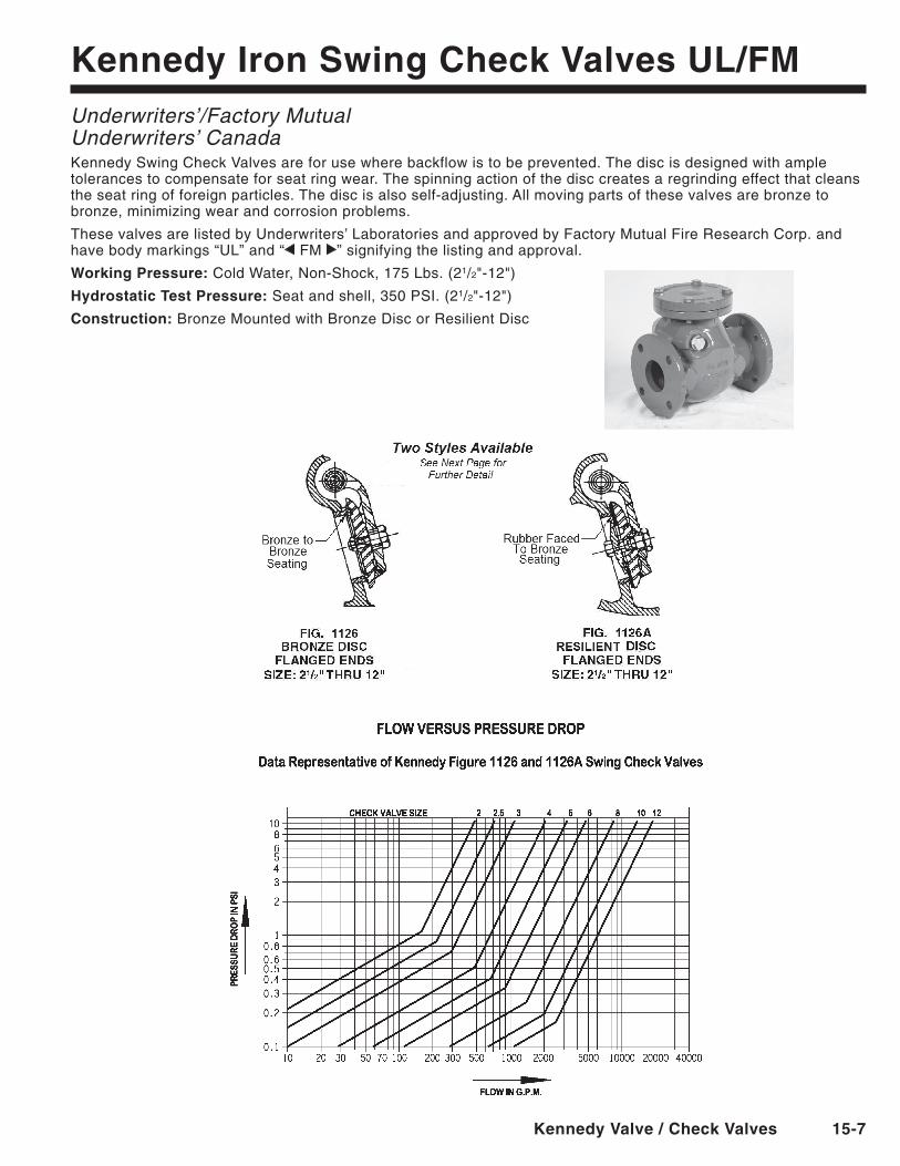
Kennedy Iron Swing Check Valves Ul/FMUnderwriters’/Factory MutualUnderwriters’ CanadaKennedy Swing Check Valves are for use where backflow is to be prevented. The disc is designed with ample tolerances to compensate for seat ring wear. The spinning action of the disc creates a regrinding effect that cleans the seat ring of foreign particles. The disc is also self-adjusting. All moving parts of these valves are bronze to bronze, minimizing wear and corrosion problems.
These valves are listed by Underwriters’ Laboratories and approved by Factory Mutual Fire Research Corp. and have body markings “UL” and “ FM ” signifying the listing and approval.
Working Pressure: Cold Water, Non-Shock, 175 Lbs. (21/2"-12")
hydrostatic Test Pressure: Seat and shell, 350 PSI. (21/2"-12")
Construction: BronzeMountedwithBronzeDiscorResilientDisc
15-8 Kennedy Valve / Check Valves
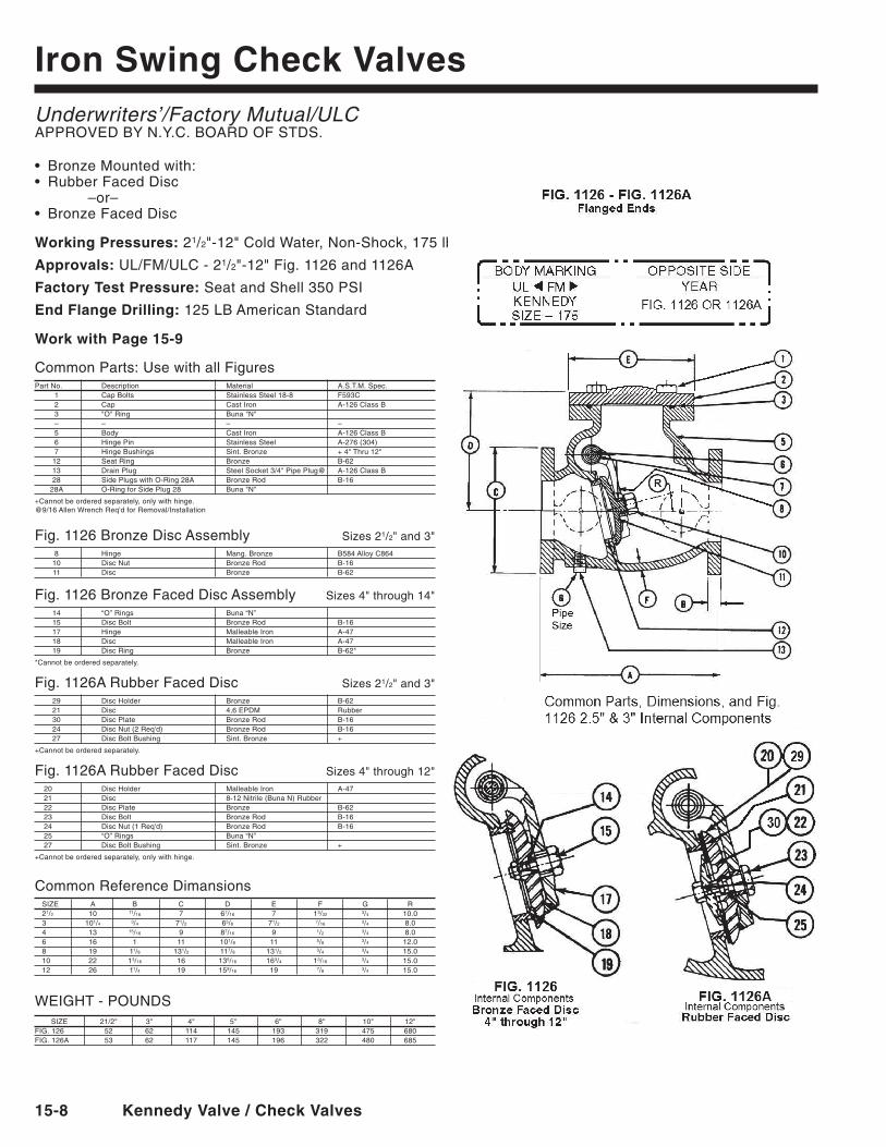
Iron Swing Check ValvesUnderwriters’/Factory Mutual/ULCAPPROVEDBYN.Y.C.BOARDOFSTDS.
• BronzeMountedwith:• RubberFacedDisc –or–• BronzeFacedDisc
Working Pressures: 21/2"-12"ColdWater,Non-Shock,175lbs.
Approvals: UL/FM/ULC - 21/2"-12"Fig.1126and1126A
Factory Test Pressure: Seat and Shell 350 PSI
end Flange Drilling: 125 LB American Standard
Work with Page 15-9
CommonParts:UsewithallFiguresPartNo. Description Material A.S.T.M.Spec. 1 Cap Bolts Stainless Steel 18-8 F593C 2 Cap Cast Iron A-126 Class B 3 "O"Ring Buna"N" – – – – 5 Body Cast Iron A-126 Class B 6 Hinge Pin Stainless Steel A-276 (304) 7 HingeBushings Sint.Bronze +4"Thru12" 12 Seat Ring Bronze B-62 13 DrainPlug SteelSocket3/4"PipePlug@ A-126ClassB 28 Side Plugs with O-Ring 28A Bronze Rod B-16 28A O-RingforSidePlug28 Buna"N"
+ Cannot be ordered separately, only with hinge.@9/16AllenWrenchReq'dforRemoval/Installation
Fig.1126BronzeDiscAssembly Sizes 21/2"and3" 8 Hinge Mang. Bronze B584 Alloy C864 10 DiscNut BronzeRod B-16 11 Disc Bronze B-62
Fig.1126BronzeFacedDiscAssemblySizes4"through14" 14 “O” Rings Buna “N” 15 DiscBolt BronzeRod B-16 17 Hinge Malleable Iron A-47 18 Disc MalleableIron A-47 19 DiscRing Bronze B-62*
*Cannot be ordered separately.
Fig.1126ARubberFacedDisc Sizes 21/2"and3" 29 DiscHolder Bronze B-62 21 Disc 4,6EPDM Rubber 30 DiscPlate BronzeRod B-16 24 DiscNut(2Req'd) BronzeRod B-16 27 DiscBoltBushing Sint.Bronze +
+Cannot be ordered separately.
Fig.1126ARubberFacedDisc Sizes4"through12" 20 DiscHolder MalleableIron A-47 21 Disc 8-12Nitrile(BunaN)Rubber 22 DiscPlate Bronze B-62 23 DiscBolt BronzeRod B-16 24 DiscNut(1Req'd) BronzeRod B-16 25 “O” Rings Buna “N” 27 DiscBoltBushing Sint.Bronze +
+Cannot be ordered separately, only with hinge.
CommonReferenceDimansions SIZE A B C D E F G R 21/2 10 11/16 7 67/16 7 13/32 3/4 10.0 3 101/4 3/4 71/2 65/8 71/2 7/16 3/4 8.0 4 13 15/16 9 87/16 9 1/2 3/4 8.0 6 16 1 11 101/8 11 5/8 3/4 12.0 8 19 11/8 131/2 117/8 131/2 3/4 3/4 15.0 10 22 13/16 16 135/16 163/4 13/16 3/4 15.0 12 26 11/4 19 159/16 19 7/8 3/4 15.0
WEIGHT-POUNDS SIZE 21/2" 3" 4" 5" 6" 8" 10" 12"FIG.126 52 62 114 145 193 319 475 680FIG.126A 53 62 117 145 196 322 480 685
FIG. 126 - FIG. 126AFlanged ends
Kennedy Valve / Check Valves 15-9
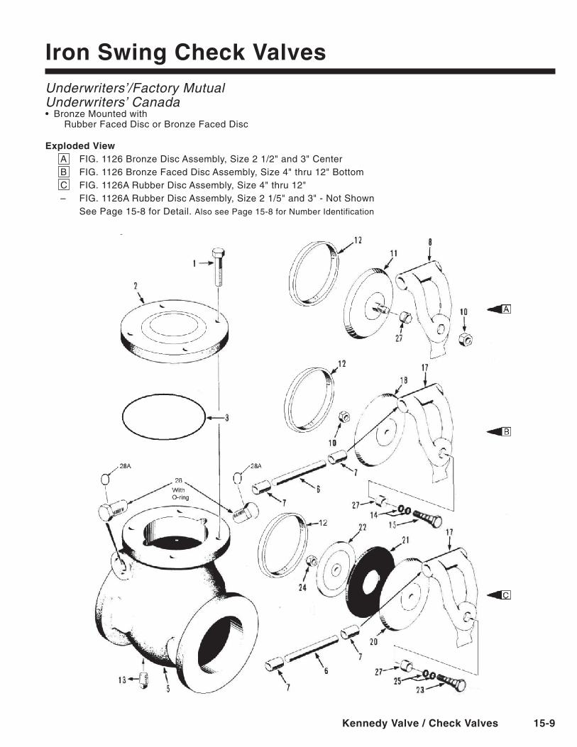
Iron Swing Check ValvesUnderwriters’/Factory MutualUnderwriters’ Canada• BronzeMountedwith RubberFacedDiscorBronzeFacedDisc
exploded ViewA FIG.1126BronzeDiscAssembly,Size21/2"and3"CenterB FIG.1126BronzeFacedDiscAssembly,Size4"thru12"BottomC FIG.1126ARubberDiscAssembly,Size4"thru12"– FIG.1126ARubberDiscAssembly,Size21/5"and3"-NotShown SeePage15-8forDetail.Also see Page 15-8 for Number Identification
15-10 Kennedy Valve / Check Valves
Features
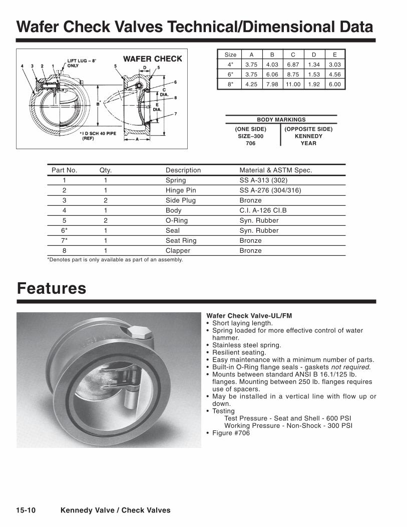
Wafer Check Valve-Ul/FM• Shortlayinglength.• Springloadedformoreeffectivecontrolofwater
hammer.• Stainlesssteelspring.• Resilientseating.• Easymaintenancewithaminimumnumberofparts.• Built-inO-Ringflangeseals-gasketsnot required.• MountsbetweenstandardANSIB16.1/125lb.
flanges. Mounting between 250 lb. flanges requires use of spacers.• May be installed in a vertical linewith flow up or
down.• Testing Test Pressure - Seat and Shell - 600 PSI Working Pressure - Non-Shock - 300 PSI• Figure#706
Size A B C D E
4" 3.75 4.03 6.87 1.34 3.03
6" 3.75 6.06 8.75 1.53 4.56
8" 4.25 7.98 11.00 1.92 6.00
BODy MARKInGS
(One SIDe) (OPPOSITe SIDe) SIZe–300 KenneDy 706 yeAR
Wafer Check Valves Technical/Dimensional Data
PartNo. Qty. Description Material&ASTMSpec.
1 1 Spring SS A-313 (302)
2 1 Hinge Pin SS A-276 (304/316)
3 2 Side Plug Bronze
4 1 Body C.I. A-126 CI.B
5 2 O-Ring Syn. Rubber
6* 1 Seal Syn. Rubber
7* 1 Seat Ring Bronze
8 1 Clapper Bronze*Denotespartisonlyavailableaspartofanassembly.
Kennedy Valve / Check Valves 15-11
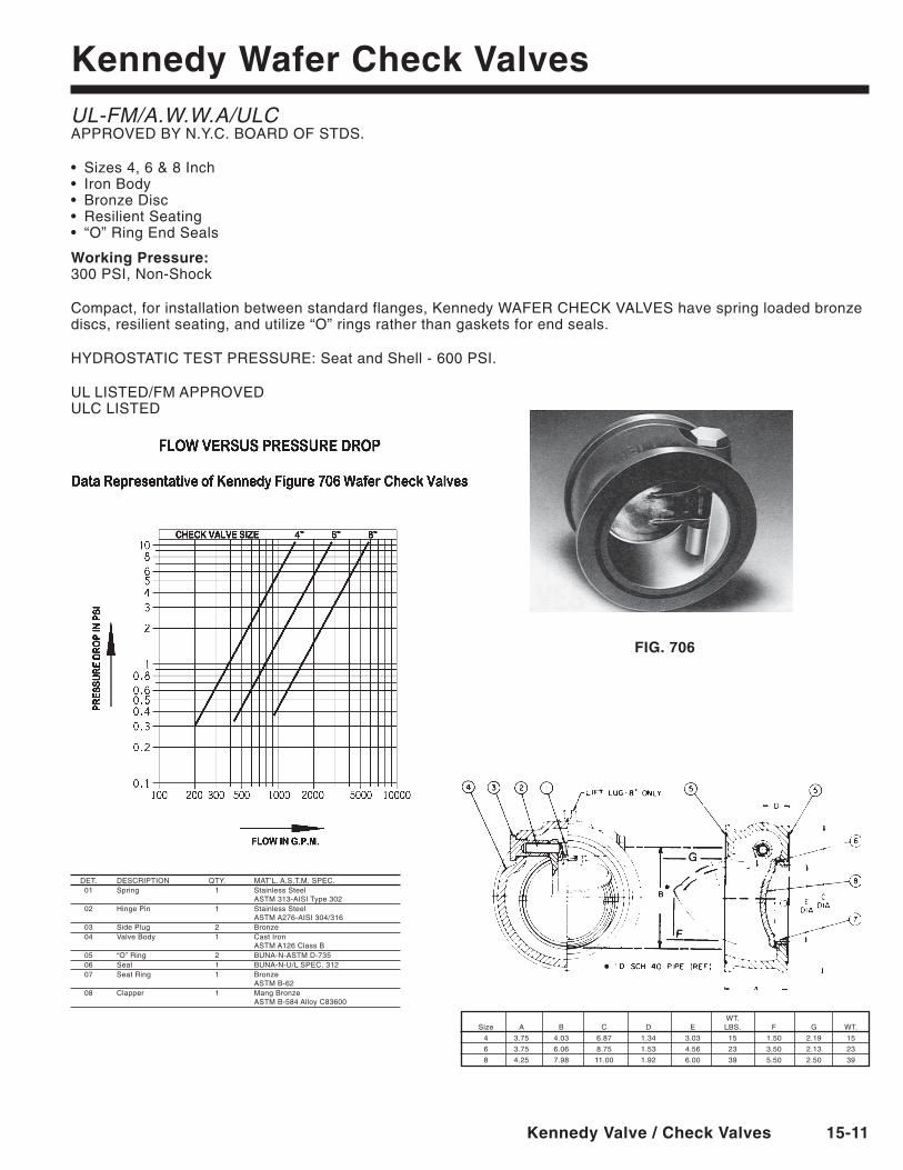
DET. DESCRIPTION QTY. MAT’L.A.S.T.M.SPEC. 01 Spring 1 Stainless Steel ASTM 313-AISI Type 302 02 Hinge Pin 1 Stainless Steel ASTM A276-AISI 304/316 03 Side Plug 2 Bronze 04 Valve Body 1 Cast Iron ASTM A126 Class B 05 “O”Ring 2 BUNA-N-ASTMD-735 06 Seal 1 BUNA-N-U/L SPEC. 312 07 Seat Ring 1 Bronze ASTM B-62 08 Clapper 1 Mang Bronze ASTM B-584 Alloy C83600
WT. Size A B C D E LBS. F G WT.
4 3.75 4.03 6.87 1.34 3.03 15 1.50 2.19 15
6 3.75 6.06 8.75 1.53 4.56 23 3.50 2.13 23
8 4.25 7.98 11.00 1.92 6.00 39 5.50 2.50 39
FIG. 706
Kennedy Wafer Check ValvesUL-FM/A.W.W.A/ULCAPPROVEDBYN.Y.C.BOARDOFSTDS.
• Sizes4,6&8Inch• IronBody• BronzeDisc• ResilientSeating• “O”RingEndSeals
Working Pressure:300 PSI, Non-Shock
Compact, for installation between standard flanges, Kennedy WAFER CHECK VALVES have spring loaded bronze discs, resilient seating, and utilize “O” rings rather than gaskets for end seals.
HYDROSTATICTESTPRESSURE:SeatandShell-600PSI.
ULLISTED/FMAPPROVED ULCLISTED

15-12 Kennedy Valve / Check Valves
PARTS lIST ITeM nO. QTy. PART nAMe MATeRIAl 1 1 ValveBody DuctileIron 2 3 Nut Plated 3 1 Cover Cast Iron 4 3 Bolt Plated 5 1 CoverSeal SBRDuro55-65 6 1 Hinge Support Stainless Steel 7 2 Nut Stainless Steel 8 2 Washer Red Fiber 9 2 Hinge Support Bolt Stainless Steel 10 1 Hinge Pin Stainless Steel 11 1 Hinge Stainless Steel 12 1 ValveDisk EPDM 13 1 DiskPlate StainlessSteel 14 1 DiskHolder CastIron* 15 1 DiskNut StainlessSteel 16 1 Seal Washer Red Fiber ** 17 1 DiskBolt StainlessSteel 18 1 Seat Ring Tin Plated Bronze 19 1 DrainPlug ZincPlated
**6 and 8 in. sizes only (others are integral to hinge)**2.5, 3 and 4 in. sizes only
Grooved Check Valves
FIGURE 426UL LISTED/FM APPROVEDSIZES 21/2", 3", 4", 6", 8"Working Pressure: 250 PSI
TheKennedyFigure426GroovedEndSwingCheckValveisalightweightunitthatfeaturesatopaccesscoverforfield maintenance. The valves are intended to be easily installed with approved grooved couplings. They may be installed either with the flow in a vertical position or horizontally. All valves have a 1/2"NPTconnectionontheinletside for installation of a 1/2"Balldrip.
DIMenSIOnAl DATA Height Width A B 2.5" = 7.22 8.625 3" = 7.68 9.120 4" = 8.54 9.990 6" = 11.34 13.280 8" = 12.86 14.500
WeIGhT/POUnDS 2.5" = 19lb. 3" = 21lb. 4" = 29lb. 6" = 61lb. 8" = 81lb.
Kennedy Valve / Check Valves 15-13
Kennedy Grooved Check Valves
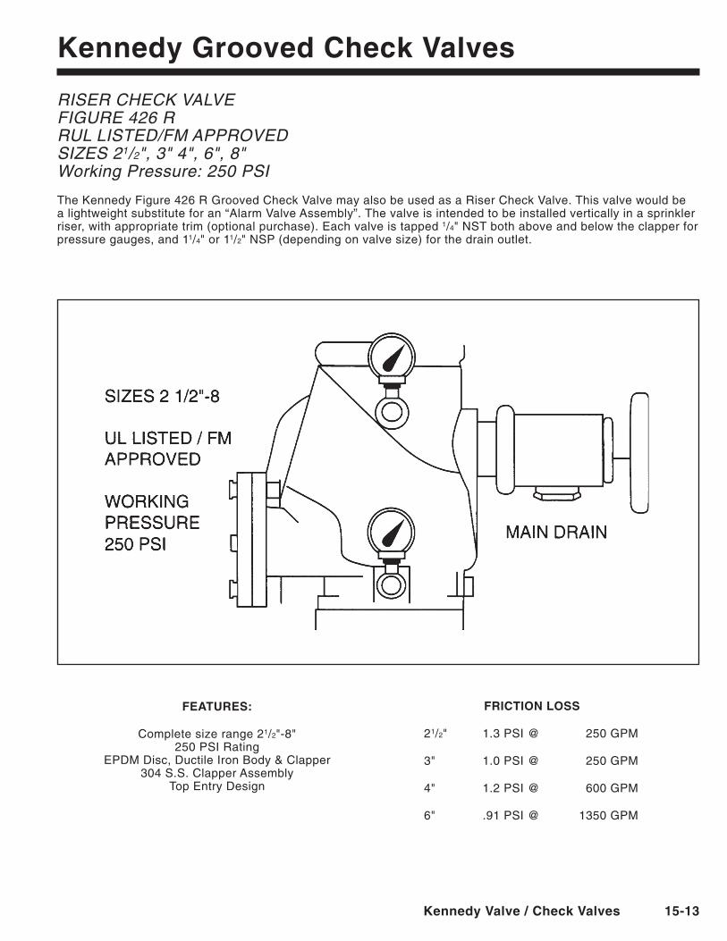
RISER CHECK VALVEFIGURE 426 RRUL LISTED/FM APPROVEDSIZES 21/2", 3" 4", 6", 8"Working Pressure: 250 PSI
TheKennedyFigure426RGroovedCheckValvemayalsobeusedasaRiserCheckValve.Thisvalvewouldbea lightweight substitute for an “Alarm Valve Assembly”. The valve is intended to be installed vertically in a sprinkler riser, with appropriate trim (optional purchase). Each valve is tapped 1/4"NSTbothaboveandbelowtheclapperforpressure gauges, and 11/4"or11/2"NSP(dependingonvalvesize)forthedrainoutlet.
FeATUReS:
Complete size range 21/2"-8"250 PSI Rating
EPDMDisc,DuctileIronBody&Clapper304 S.S. Clapper Assembly
TopEntryDesign
FRICTIOn lOSS
21/2" 1.3PSI@ 250GPM
3" 1.0PSI@ 250GPM
4" 1.2PSI@ 600GPM
6" .91PSI@ 1350GPM
15-14 Kennedy Valve / Check Valves
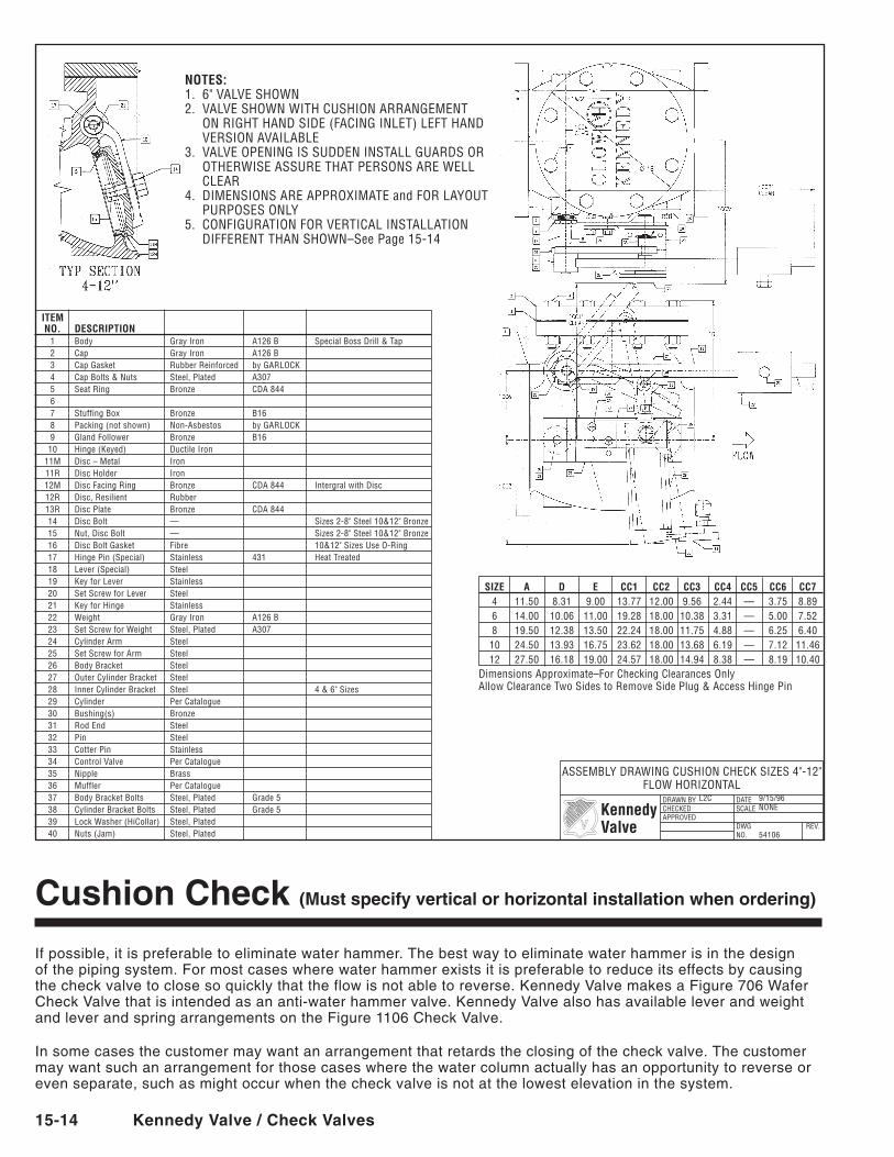
Cushion Check (Must specify vertical or horizontal installation when ordering)
If possible, it is preferable to eliminate water hammer. The best way to eliminate water hammer is in the design of the piping system. For most cases where water hammer exists it is preferable to reduce its effects by causing the check valve to close so quickly that the flow is not able to reverse. Kennedy Valve makes a Figure 706 Wafer Check Valve that is intended as an anti-water hammer valve. Kennedy Valve also has available lever and weight and lever and spring arrangements on the Figure 1106 Check Valve.
In some cases the customer may want an arrangement that retards the closing of the check valve. The customer may want such an arrangement for those cases where the water column actually has an opportunity to reverse or even separate, such as might occur when the check valve is not at the lowest elevation in the system.
NOTES:1. 6" VALVE SHoWN2. VALVE SHoWN WITH CUSHIoN ARRANGEMENT
oN RIGHT HAND SIDE (FACING INLET) LEFT HAND VERSIoN AVAILABLE
3. VALVE oPENING IS SUDDEN INSTALL GUARDS oR oTHERWISE ASSURE THAT PERSoNS ARE WELL CLEAR
4. DIMENSIoNS ARE APPRoXIMATE and FoR LAYoUT PURPoSES oNLY
5. CoNFIGURATIoN FoR VERTICAL INSTALLATIoN DIFFERENT THAN SHoWN–See Page 15-14
DRAWN BYCHECKEDAPPRoVED
DATESCALE
DWGNo.
REV.
KennedyValve
ASSEMBLY DRAWING CUSHIoN CHECK SIZES 4"-12" FLoW HoRIZoNTAL
L2C 9/15/96 NoNE 54106
SIZE A D E CC1 CC2 CC3 CC4 CC5 CC6 CC7 4 11.50 8.31 9.00 13.77 12.00 9.56 2.44 — 3.75 8.89 6 14.00 10.06 11.00 19.28 18.00 10.38 3.31 — 5.00 7.52 8 19.50 12.38 13.50 22.24 18.00 11.75 4.88 — 6.25 6.40 10 24.50 13.93 16.75 23.62 18.00 13.68 6.19 — 7.12 11.46 12 27.50 16.18 19.00 24.57 18.00 14.94 8.38 — 8.19 10.40Dimensions Approximate–For Checking Clearances only Allow Clearance Two Sides to Remove Side Plug & Access Hinge Pin
ITEM NO. DESCRIPTION 1 Body Gray Iron A126 B Special Boss Drill & Tap 2 Cap Gray Iron A126 B 3 Cap Gasket Rubber Reinforced by GARLoCK 4 Cap Bolts & Nuts Steel, Plated A307 5 Seat Ring Bronze CDA 844 6 7 Stuffing Box Bronze B16 8 Packing (not shown) Non-Asbestos by GARLoCK 9 Gland Follower Bronze B16 10 Hinge (Keyed) Ductile Iron 11M Disc – Metal Iron 11R Disc Holder Iron 12M Disc Facing Ring Bronze CDA 844 Intergral with Disc 12R Disc, Resilient Rubber 13R Disc Plate Bronze CDA 844 14 Disc Bolt — Sizes 2-8" Steel 10&12" Bronze 15 Nut, Disc Bolt — Sizes 2-8" Steel 10&12" Bronze 16 Disc Bolt Gasket Fibre 10&12" Sizes Use o-Ring 17 Hinge Pin (Special) Stainless 431 Heat Treated 18 Lever (Special) Steel 19 Key for Lever Stainless 20 Set Screw for Lever Steel 21 Key for Hinge Stainless 22 Weight Gray Iron A126 B 23 Set Screw for Weight Steel, Plated A307 24 Cylinder Arm Steel 25 Set Screw for Arm Steel 26 Body Bracket Steel 27 outer Cylinder Bracket Steel 28 Inner Cylinder Bracket Steel 4 & 6" Sizes 29 Cylinder Per Catalogue 30 Bushing(s) Bronze 31 Rod End Steel 32 Pin Steel 33 Cotter Pin Stainless 34 Control Valve Per Catalogue 35 Nipple Brass 36 Muffler Per Catalogue 37 Body Bracket Bolts Steel, Plated Grade 5 38 Cylinder Bracket Bolts Steel, Plated Grade 5 39 Lock Washer (HiCollar) Steel, Plated 40 Nuts (Jam) Steel, Plated
Kennedy Valve / Check Valves 15-15
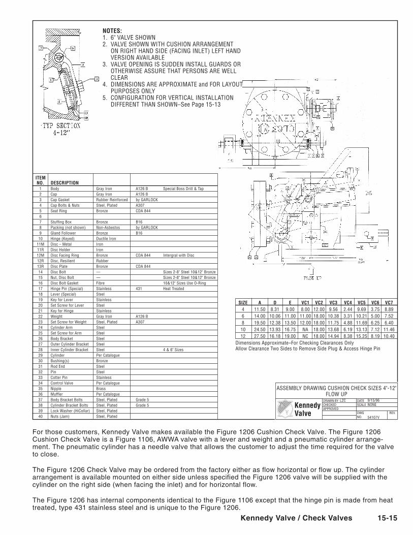
For those customers, Kennedy Valve makes available the Figure 1206 Cushion Check Valve. The Figure 1206 Cushion Check Valve is a Figure 1106, AWWA valve with a lever and weight and a pneumatic cylinder arrange-ment. The pneumatic cylinder has a needle valve that allows the customer to adjust the time required for the valve to close.
The Figure 1206 Check Valve may be ordered from the factory either as flow horizontal or flow up. The cylinder arrangement is available mounted on either side unless specified the Figure 1206 valve will be supplied with the cylinder on the right side (when facing the inlet) and for horizontal flow.
The Figure 1206 has internal components identical to the Figure 1106 except that the hinge pin is made from heat treated, type 431 stainless steel and is unique to the Figure 1206.
NOTES:1. 6" VALVE SHoWN2. VALVE SHoWN WITH CUSHIoN ARRANGEMENT
oN RIGHT HAND SIDE (FACING INLET) LEFT HAND VERSIoN AVAILABLE
3. VALVE oPENING IS SUDDEN INSTALL GUARDS oR oTHERWISE ASSURE THAT PERSoNS ARE WELL CLEAR
4. DIMENSIoNS ARE APPRoXIMATE and FoR LAYoUT PURPoSES oNLY
5. CoNFIGURATIoN FoR VERTICAL INSTALLATIoN DIFFERENT THAN SHoWN–See Page 15-13
DRAWN BYCHECKEDAPPRoVED
DATESCALE
DWGNo.
REV.
KennedyValve
ASSEMBLY DRAWING CUSHIoN CHECK SIZES 4"-12" FLoW UP
L2C 9/15/96 NoNE
54107V
ITEM NO. DESCRIPTION 1 Body Gray Iron A126 B Special Boss Drill & Tap 2 Cap Gray Iron A126 B 3 Cap Gasket Rubber Reinforced by GARLoCK 4 Cap Bolts & Nuts Steel, Plated A307 5 Seat Ring Bronze CDA 844 6 7 Stuffing Box Bronze B16 8 Packing (not shown) Non-Asbestos by GARLoCK 9 Gland Follower Bronze B16 10 Hinge (Keyed) Ductile Iron 11M Disc – Metal Iron 11R Disc Holder Iron 12M Disc Facing Ring Bronze CDA 844 Intergral with Disc 12R Disc, Resilient Rubber 13R Disc Plate Bronze CDA 844 14 Disc Bolt — Sizes 2-8" Steel 10&12" Bronze 15 Nut, Disc Bolt — Sizes 2-8" Steel 10&12" Bronze 16 Disc Bolt Gasket Fibre 10&12" Sizes Use o-Ring 17 Hinge Pin (Special) Stainless 431 Heat Treated 18 Lever (Special) Steel 19 Key for Lever Stainless 20 Set Screw for Lever Steel 21 Key for Hinge Stainless 22 Weight Gray Iron A126 B 23 Set Screw for Weight Steel, Plated A307 24 Cylinder Arm Steel 25 Set Screw for Arm Steel 26 Body Bracket Steel 27 outer Cylinder Bracket Steel 28 Inner Cylinder Bracket Steel 4 & 6" Sizes 29 Cylinder Per Catalogue 30 Bushing(s) Bronze 31 Rod End Steel 32 Pin Steel 33 Cotter Pin Stainless 34 Control Valve Per Catalogue 35 Nipple Brass 36 Muffler Per Catalogue 37 Body Bracket Bolts Steel, Plated Grade 5 38 Cylinder Bracket Bolts Steel, Plated Grade 5 39 Lock Washer (HiCollar) Steel, Plated 40 Nuts (Jam) Steel, Plated
SIZE A D E VC1 VC2 VC3 VC4 VC5 VC6 VC7 4 11.50 8.31 9.00 8.00 12.00 9.56 2.44 9.69 3.75 8.89 6 14.00 10.06 11.00 11.00 18.00 10.38 3.31 10.21 5.00 7.52 8 19.50 12.38 13.50 12.00 18.00 11.75 4.88 11.69 6.25 6.40 10 24.50 13.93 16.75 NA 18.00 13.68 6.19 13.13 7.12 11.46 12 27.50 16.18 19.00 NC 18.00 14.94 8.38 15.25 8.19 10.40Dimensions Approximate–For Checking Clearances only Allow Clearance Two Sides to Remove Side Plug & Access Hinge Pin
15-16 Kennedy Valve / Check Valves
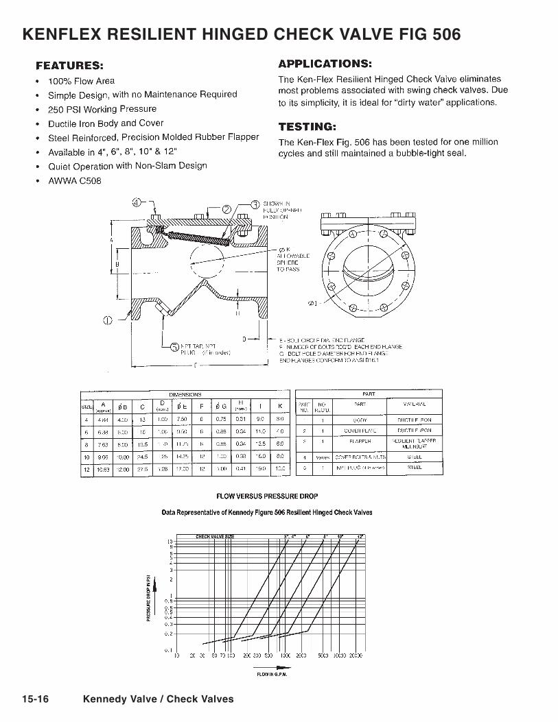
KenFleX ReSIlIenT hInGeD CheCK VAlVe FIG 506
Kennedy Valve / Check Valves 15-17
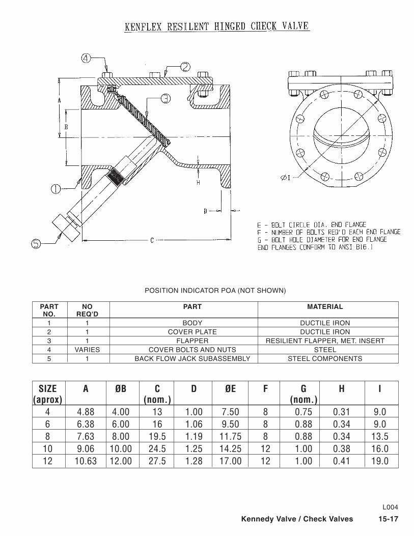
SIZE A ØB C D ØE F G H I (aprox) (nom.) (nom.) 4 4.88 4.00 13 1.00 7.50 8 0.75 0.31 9.0 6 6.38 6.00 16 1.06 9.50 8 0.88 0.34 9.0 8 7.63 8.00 19.5 1.19 11.75 8 0.88 0.34 13.5 10 9.06 10.00 24.5 1.25 14.25 12 1.00 0.38 16.0 12 10.63 12.00 27.5 1.28 17.00 12 1.00 0.41 19.0
L004
POSITIONINDICATORPOA(NOTSHOWN)
PART nO PART MATeRIAl nO. ReQ'D 1 1 BODY DUCTILEIRON 2 1 COVERPLATE DUCTILEIRON 3 1 FLAPPER RESILIENT FLAPPER, MET. INSERT 4 VARIES COVERBOLTSANDNUTS STEEL 5 1 BACKFLOWJACKSUBASSEMBLY STEELCOMPONENTS
15-18 Kennedy Valve / Check Valves
DRAW
N BY
CHEC
KED
APPR
oVED
DATE
SCAL
E
DWG
No.
REV.
Kenn
edy
Valv
e
INCR
EASI
NG
CH
ECK
DIM
ENSI
oN
S W
/LEV
ER &
WEI
GH
T
PM
P 5-
2-01
N
oN
E
31
946
FE
AT
UR
ES
:
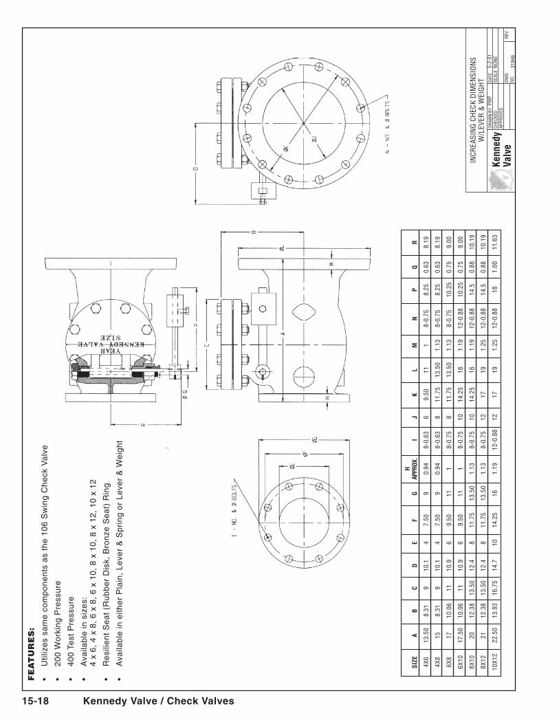
•Utilizessamecomponentsasthe106SwingCheckValve
•200WorkingPressure
•400TestPressure
•Availableinsizes:
4
x 6
, 4
x 8
, 6
x 8
, 6
x 1
0,
8 x
10
, 8
x 1
2,
10
x 1
2
•ResilientSeat(RubberDisk,BronzeSeat)Ring
•AvailableineitherPlain,Lever&SpringorLever&Weight
H
SI
ZE
A B
C D
E
F G
AP
PROX
. I
J K
L M
N
P
Q
R
4X
6 13
.50
8.31
9
10.1
4
7.50
9
0.94
8-
0.63
6
9.50
11
1
8-0.
75
8.25
0.
63
8.19
4X
8 15
8.
31
9 10
.1
4 7.
50
9 0.
94
8-0.
63
8 11
.75
13.5
0 1.
13
8-0.
75
8.25
0.
63
8.19
6X
8 17
10
.06
11
10.9
6
9.50
11
1
8-0.
75
8 11
.75
13.5
0 1.
13
8-0.
75
10.2
5 0.
75
9.00
6X
10
17.5
0 10
.06
11
10.9
6
9.50
11
1
8-0.
75
10
14.2
5 16
1.
19
12-0
.88
10.2
5 0.
75
9.00
8X
10
20
12.3
8 13
.50
12.4
8
11.7
5 13
.50
1.13
8-
0.75
10
14
.25
16
1.19
12
-0.8
8 14
.5
0.88
10
.19
8X
12
21
12.3
8 13
.50
12.4
8
11.7
5 13
.50
1.13
8-
0.75
12
17
19
1.
25
12-0
.88
14.5
0.
88
10.1
9
10
X12
22.5
0 13
.93
16.7
5 14
.7
10
14.2
5 16
1.
19
12-0
.88
12
17
19
1.25
12
-0.8
8 18
1.
00
11.6
3
Kennedy Valve / Check Valves 15-19
DRAW
N BY
CHEC
KED
APPR
oVED
DATE
SCAL
E
DWG
No.
REV.
Kenn
edy
Valv
e
INCR
EASI
NG
CH
ECK
DIM
ENSI
oN
S W
/SPR
ING
& L
EVER
PMP
5-2-
01
No
NE
31
935
SI
ZE
A B
C D
E
F G
H
I
J K
L M
N
4X
6 13
.50
8.31
9
8.19
4
7.50
9
0.94
8-
0.63
6
9.50
11
1
8-0.
75
4X
8 15
8.
31
9 8.
19
4 7.
50
9 0.
94
8-0.
63
8 11
.75
13.5
0 1.
13
8-0.
75
6X
8 17
10
.06
11
9 6
9.50
11
1
8-0.
75
8 11
.75
13.5
0 1.
13
8-0.
75
6X
10
17.5
0 10
.06
11
9 6
9.50
11
1
8-0.
75
10
14.2
5 16
1.
19
12-0
.88
8X
10
20
12.3
8 13
.50
10.1
9 8
11.7
5 13
.50
1.13
8-
0.75
10
14
.25
16
1.19
12
-0.8
8
8X
12
21
12.3
8 13
.50
10.1
9 8
11.7
5 13
.50
1.13
8-
0.75
12
17
19
1.
25
12-0
.88
10
X12
22.5
0 13
.93
16.7
5 11
.63
10
14.2
5 16
1.
19
12-0
.88
12
17
19
1.25
12
-0.8
8
FE
AT
UR
ES
:
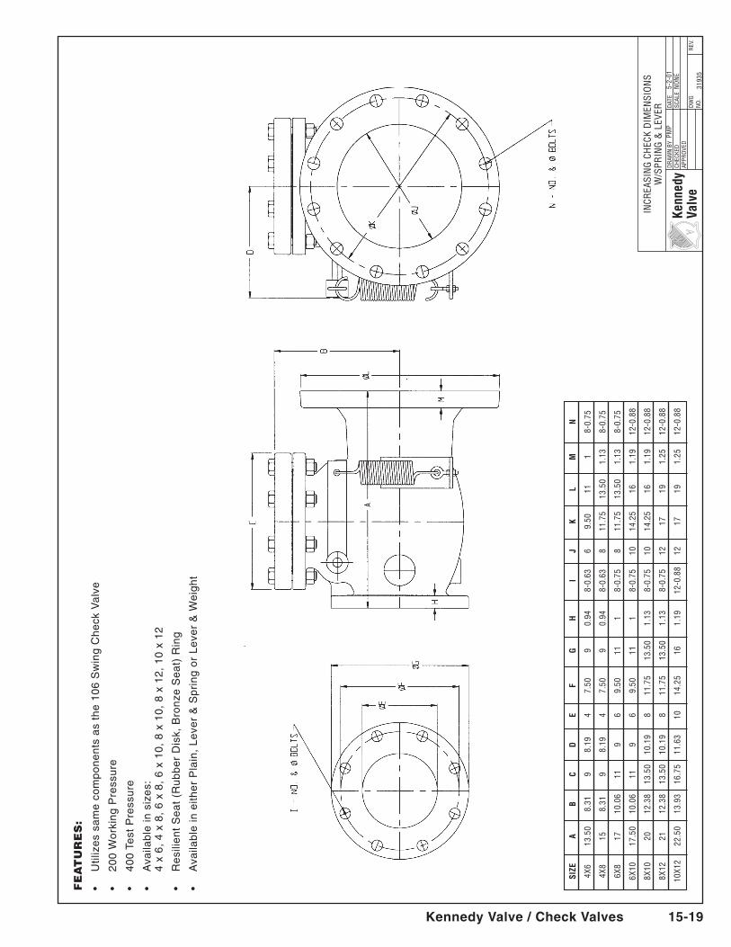
•Utilizessamecomponentsasthe106SwingCheckValve
•200WorkingPressure
•400TestPressure
•Availableinsizes:
4
x 6
, 4
x 8
, 6
x 8
, 6
x 1
0,
8 x
10
, 8
x 1
2,
10
x 1
2
•ResilientSeat(RubberDisk,BronzeSeat)Ring
•AvailableineitherPlain,Lever&SpringorLever&Weight
KENNEDY VALVE MODEL KS-FW
Kennedy Valve/KS-FW C509 3-1
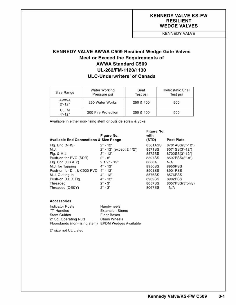
KENNEDY VALVE AWWA C509 Resilient Wedge Gate ValvesMeet or Exceed the Requirements of
AWWA Standard C509UL-262/FM-1120/1130
ULC-Underwriters’ of Canada
Water Working Seat Hydrostatic Shell Size Range Pressure psi Test psi Test psi
AWWA 2"-12" 250 Water Works 250 & 400 500
ULFM 4"-12" 200 Fire Protection 250 & 400 500
Available in either non-rising stem or outside screw & yoke.
Figure No. Figure No. with Available End Connections & Size Range (STD) Post Plate
Flg. End (NRS) 2" - 12" 8561ASS 8701ASS(3"-12")M.J. 2" - 12" (except 2 1/2") 8571SS 8071SS(3"-12")Flg. & M.J. 3" - 12" 8572SS 8702SS(3"-12")Push-on for PVC (SDR) 2" - 8" 8597SS 8597PSS(3"-8")Flg. End (OS & Y) 2 1/2" - 12" 8068A N/AM.J. for Tapping 4" - 12" 8950SS 8950PSSPush-on for D.I. & C900 PVC 4" - 12" 8901SS 8901PSSM.J. Cutting-in 4" - 12" 8576SS 8576PSSPush-on D.I. X Flg. 4" - 12" 8902SS 8902PSSThreaded 2" - 3" 8057SS 8057PSS(3"only)Threaded (OS&Y) 2" - 3" 8067SS N/A
Accessories
Indicator Posts Handwheels“T” Handles Extension StemsStem Guides Floor Boxes2" Sq. Operating Nuts Chain WheelsFloorstands (non-rising stem) EPDM Wedges Available
2" size not UL Listed
KENNEDY VALVE KS-FW RESILIENT
WEDGE VALVES
KENNEDY VALVE
KENNEDY VALVE MODEL KS-FW
3-2 Kennedy Valve/KS-FW C509
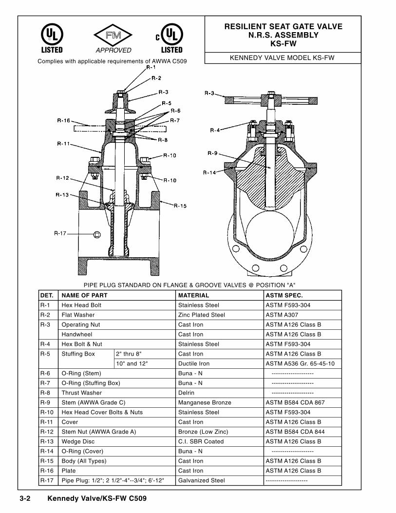
DET. NAME OF PART MATERIAL ASTM SPEC.
R-1 Hex Head Bolt Stainless Steel ASTM F593-304
R-2 Flat Washer Zinc Plated Steel ASTM A307
R-3 Operating Nut Cast Iron ASTM A126 Class B
Handwheel Cast Iron ASTM A126 Class B
R-4 Hex Bolt & Nut Stainless Steel ASTM F593-304
R-5 Stuffing Box 2" thru 8" Cast Iron ASTM A126 Class B
10" and 12" Ductile Iron ASTM A536 Gr. 65-45-10
R-6 O-Ring (Stem) Buna - N --------------------
R-7 O-Ring (Stuffing Box) Buna - N --------------------
R-8 Thrust Washer Delrin --------------------
R-9 Stem (AWWA Grade C) Manganese Bronze ASTM B584 CDA 867
R-10 Hex Head Cover Bolts & Nuts Stainless Steel ASTM F593-304
R-11 Cover Cast Iron ASTM A126 Class B
R-12 Stem Nut (AWWA Grade A) Bronze (Low Zinc) ASTM B584 CDA 844
R-13 Wedge Disc C.I. SBR Coated ASTM A126 Class B
R-14 O-Ring (Cover) Buna - N --------------------
R-15 Body (All Types) Cast Iron ASTM A126 Class B
R-16 Plate Cast Iron ASTM A126 Class B
R-17 Pipe Plug: 1/2"; 2 1/2"-4"--3/4"; 6'-12" Galvanized Steel --------------------
RESILIENT SEAT GATE VALVEN.R.S. ASSEMbLY
KS-FW
Complies with applicable requirements of AWWA C509
PIPE PLUG STANDARD ON FLANGE & GROOVE VALVES @ POSITION "A"
KENNEDY VALVE MODEL KS-FW
Kennedy Valve/KS-FW C509 3-3
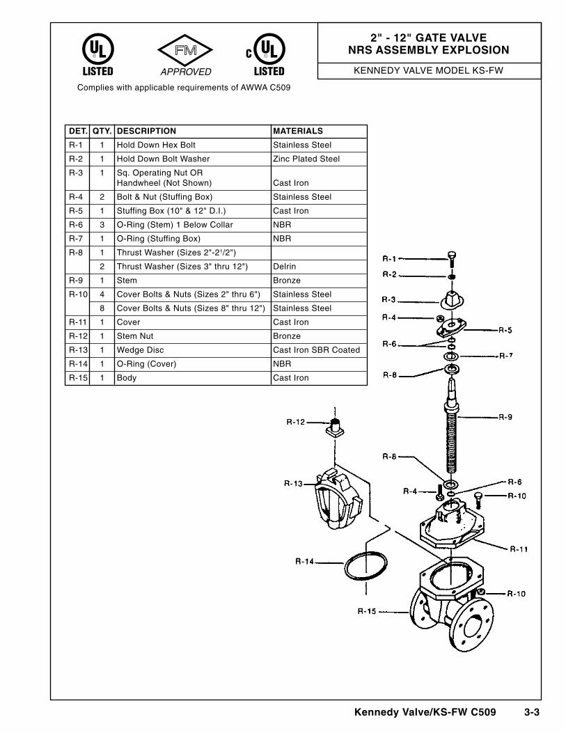
2" - 12" GATE VALVENRS ASSEMbLY ExPLOSION
DET. QTY. DESCRIPTION MATERIALS
R-1 1 Hold Down Hex Bolt Stainless Steel
R-2 1 Hold Down Bolt Washer Zinc Plated Steel
R-3 1 Sq. Operating Nut OR Handwheel (Not Shown) Cast Iron
R-4 2 Bolt & Nut (Stuffing Box) Stainless Steel
R-5 1 Stuffing Box (10" & 12" D.I.) Cast Iron
R-6 3 O-Ring (Stem) 1 Below Collar NBR
R-7 1 O-Ring (Stuffing Box) NBR
R-8 1 Thrust Washer (Sizes 2"-21/2")
2 Thrust Washer (Sizes 3" thru 12") Delrin
R-9 1 Stem Bronze
R-10 4 Cover Bolts & Nuts (Sizes 2" thru 6") Stainless Steel
8 Cover Bolts & Nuts (Sizes 8" thru 12") Stainless Steel
R-11 1 Cover Cast Iron
R-12 1 Stem Nut Bronze
R-13 1 Wedge Disc Cast Iron SBR Coated
R-14 1 O-Ring (Cover) NBR
R-15 1 Body Cast Iron
Complies with applicable requirements of AWWA C509
KENNEDY VALVE MODEL KS-FW
3-4 Kennedy Valve/KS-FW C509
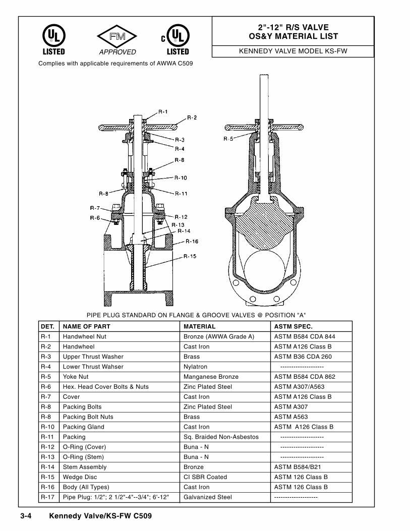
2"-12" R/S VALVEOS&Y MATERIAL LIST
Complies with applicable requirements of AWWA C509
PIPE PLUG STANDARD ON FLANGE & GROOVE VALVES @ POSITION "A"
DET. NAME OF PART MATERIAL ASTM SPEC.
R-1 Handwheel Nut Bronze (AWWA Grade A) ASTM B584 CDA 844
R-2 Handwheel Cast Iron ASTM A126 Class B
R-3 Upper Thrust Washer Brass ASTM B36 CDA 260
R-4 Lower Thrust Wahser Nylatron --------------------
R-5 Yoke Nut Manganese Bronze ASTM B584 CDA 862
R-6 Hex. Head Cover Bolts & Nuts Zinc Plated Steel ASTM A307/A563
R-7 Cover Cast Iron ASTM A126 Class B
R-8 Packing Bolts Zinc Plated Steel ASTM A307
R-8 Packing Bolt Nuts Brass ASTM A563
R-10 Packing Gland Cast Iron ASTM A126 Class B
R-11 Packing Sq. Braided Non-Asbestos --------------------
R-12 O-Ring (Cover) Buna - N --------------------
R-13 O-Ring (Stem) Buna - N --------------------
R-14 Stem Assembly Bronze ASTM B584/B21
R-15 Wedge Disc CI SBR Coated ASTM 126 Class B
R-16 Body (All Types) Cast Iron ASTM 126 Class B
R-17 Pipe Plug: 1/2"; 2 1/2"-4"--3/4"; 6'-12" Galvanized Steel --------------------
KENNEDY VALVE MODEL KS-FW
Kennedy Valve/KS-FW C509 3- 5
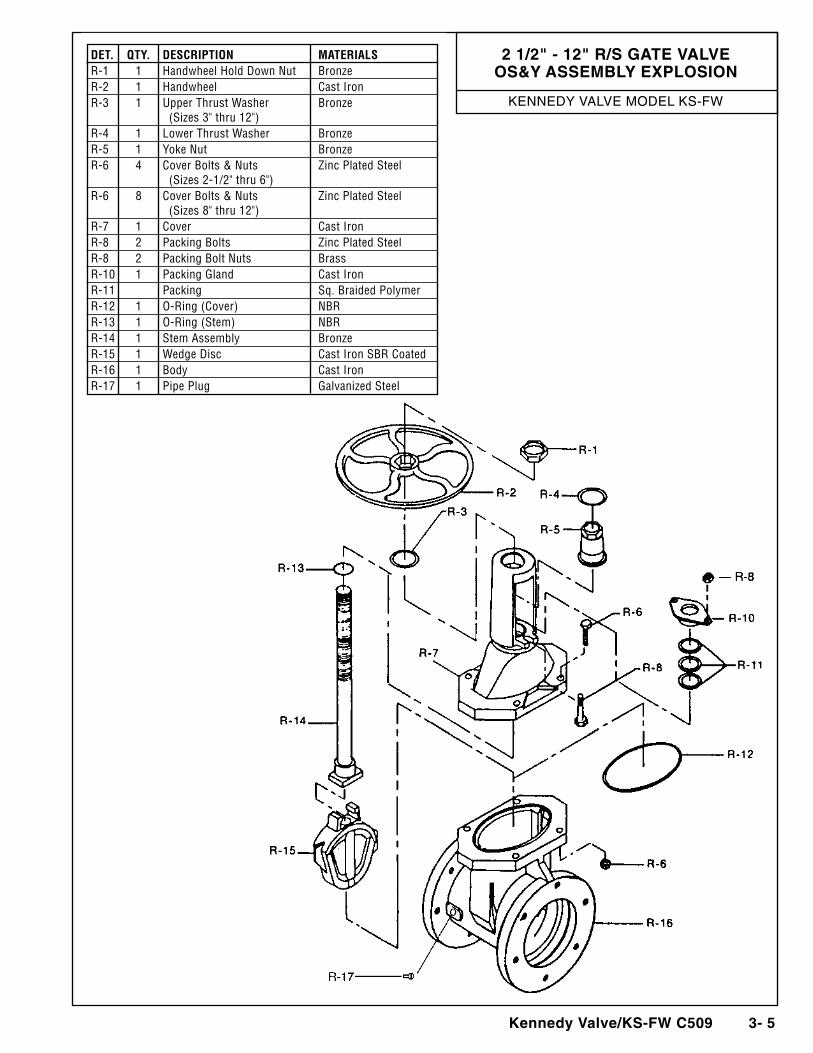
2 1/2" - 12" R/S GATE VALVEOS&Y ASSEMbLY ExPLOSION
DET. QTY. DESCRIPTION MATERIALSR-1 1 Handwheel Hold Down Nut BronzeR-2 1 Handwheel Cast IronR-3 1 Upper Thrust Washer Bronze (Sizes 3" thru 12")R-4 1 Lower Thrust Washer BronzeR-5 1 Yoke Nut BronzeR-6 4 Cover Bolts & Nuts Zinc Plated Steel (Sizes 2-1/2" thru 6")R-6 8 Cover Bolts & Nuts Zinc Plated Steel (Sizes 8" thru 12")R-7 1 Cover Cast IronR-8 2 Packing Bolts Zinc Plated SteelR-8 2 Packing Bolt Nuts BrassR-10 1 Packing Gland Cast IronR-11 Packing Sq. Braided PolymerR-12 1 O-Ring (Cover) NBRR-13 1 O-Ring (Stem) NBRR-14 1 Stem Assembly BronzeR-15 1 Wedge Disc Cast Iron SBR CoatedR-16 1 Body Cast IronR-17 1 Pipe Plug Galvanized Steel
KENNEDY VALVE MODEL KS-FW
3-6 Kennedy Valve/KS-FW C509
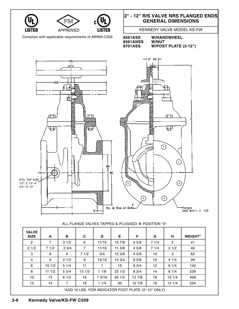
2" - 12" R/S VALVE NRS FLANGED ENDSGENERAL DIMENSIONS
Complies with applicable requirements of AWWA C509 8561ASS W/HANDWHEEL8561ANSS W/NUT8701ASS W/POST PLATE (3-12")
ALL FLANGE VALVES TAPPED & PLUGGED @ POSITION "A"
STD. TAP SIZE1/2": 2 1/2"-4"3/4": 6"-12"
VALVE SIZE A b C D E F G H WEIGHT*
2 7 3 1/2 6 11/16 10 7/8 4 5/8 7 1/4 2 41
2 1/2 7 1/2 3 3/4 7 11/16 11 3/8 4 5/8 7 1/4 2 1/2 49
3 8 4 7 1/2 3/4 12 3/8 4 5/8 10 3 62
4 9 4 1/2 9 15/16 14 3/4 8 5/8 10 4 1/4 99
6 10 1/2 5 1/4 11 1 19 8 3/4 12 6 1/4 142
8 11 1/2 5 3/4 13 1/2 1 1/8 22 1/2 8 3/4 14 8 1/4 239
10 13 6 1/2 16 1 3/16 26 1/2 12 7/8 18 10 1/4 408
12 14 7 19 1 1/4 30 12 7/8 18 12 1/4 554
*ADD 16 LBS. FOR INDICATOR POST PLATE (3"-12" ONLY)
KENNEDY VALVE MODEL KS-FW
Kennedy Valve/KS-FW C509 3- 7
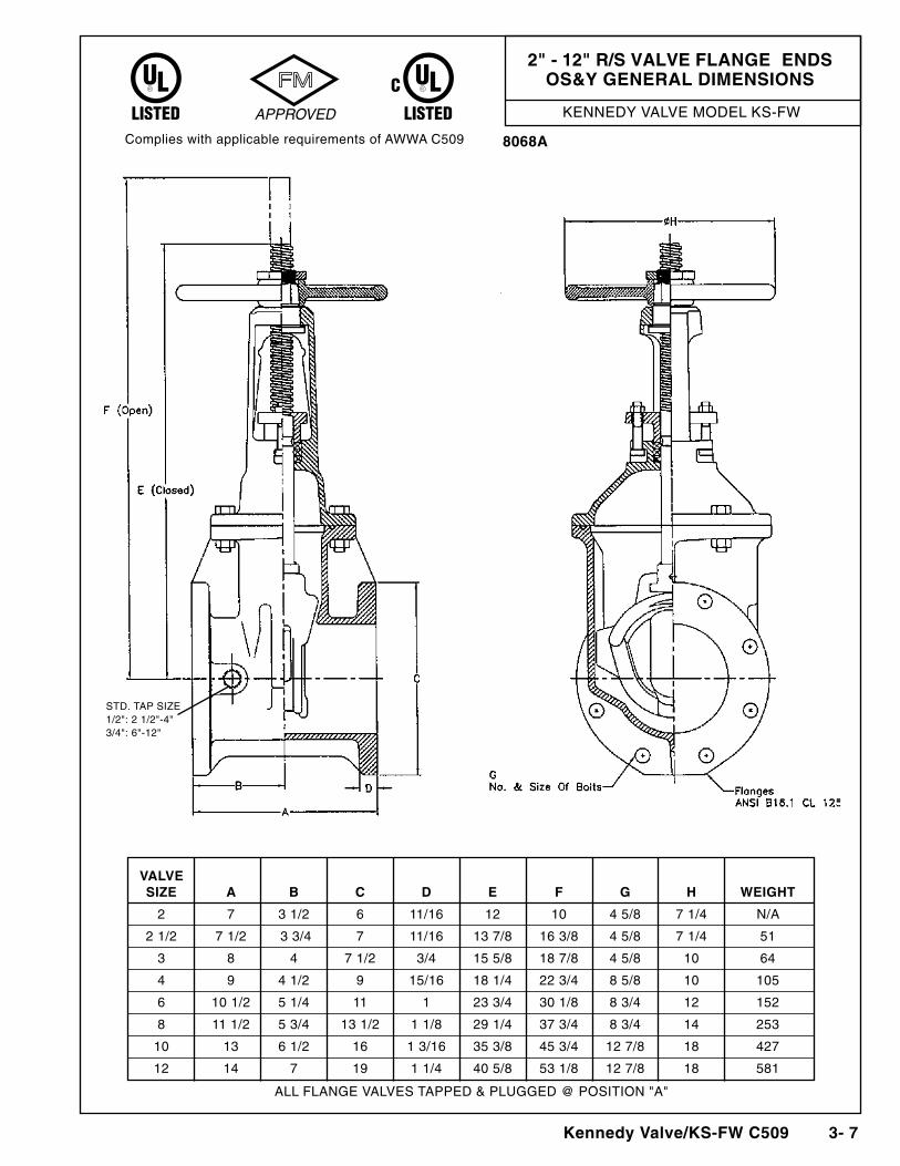
2" - 12" R/S VALVE FLANGE ENDSOS&Y GENERAL DIMENSIONS
Complies with applicable requirements of AWWA C509 8068A
STD. TAP SIZE1/2": 2 1/2"-4"3/4": 6"-12"
ALL FLANGE VALVES TAPPED & PLUGGED @ POSITION "A"
VALVE SIZE A b C D E F G H WEIGHT
2 7 3 1/2 6 11/16 12 10 4 5/8 7 1/4 N/A
2 1/2 7 1/2 3 3/4 7 11/16 13 7/8 16 3/8 4 5/8 7 1/4 51
3 8 4 7 1/2 3/4 15 5/8 18 7/8 4 5/8 10 64
4 9 4 1/2 9 15/16 18 1/4 22 3/4 8 5/8 10 105
6 10 1/2 5 1/4 11 1 23 3/4 30 1/8 8 3/4 12 152
8 11 1/2 5 3/4 13 1/2 1 1/8 29 1/4 37 3/4 8 3/4 14 253
10 13 6 1/2 16 1 3/16 35 3/8 45 3/4 12 7/8 18 427
12 14 7 19 1 1/4 40 5/8 53 1/8 12 7/8 18 581
KENNEDY VALVE MODEL KS-FW
3-8 Kennedy Valve/KS-FW C509
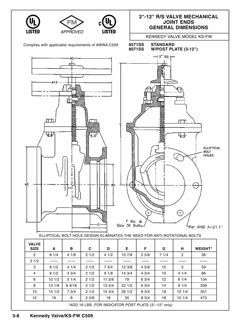
2"-12" R/S VALVE MECHANICAL JOINT ENDS
GENERAL DIMENSIONS
Complies with applicable requirements of AWWA C509 8571SS STANDARD8071SS W/POST PLATE (3-12")
ELLIPTICAL BOLT HOLE DESIGN ELIMINATES THE NEED FOR ANTI-ROTATIONAL BOLTS
ELLIPTICALBOLTHOLES
ELLIPTICALBOLTHOLES
VALVE SIZE A b C D E F G H WEIGHT*
2 8 1/4 4 1/8 2 1/2 4 1/2 10 7/8 2 5/8 7 1/4 2 36
2 1/2 —— —— —— —— —— —— —— —— ——
3 8 1/2 4 1/4 2 1/2 7 3/4 12 3/8 4 5/8 10 3 59
4 9 1/2 4 3/4 2 1/2 9 1/8 14 3/4 4 3/4 10 4 1/4 86
6 10 1/2 5 1/4 2 1/2 11 3/8 19 6 3/4 12 6 1/4 134
8 13 1/8 6 9/16 2 1/2 13 3/4 22 1/2 6 3/4 14 8 1/4 206
10 15 1/2 7 3/4 2 1/2 15 3/4 26 1/2 8 3/4 18 10 1/4 351
12 16 8 2 5/8 18 30 8 3/4 18 12 1/4 473
*ADD 16 LBS. FOR INDICATOR POST PLATE (3"–12" only)
KENNEDY VALVE MODEL KS-FW
Kennedy Valve/KS-FW C509 3-9
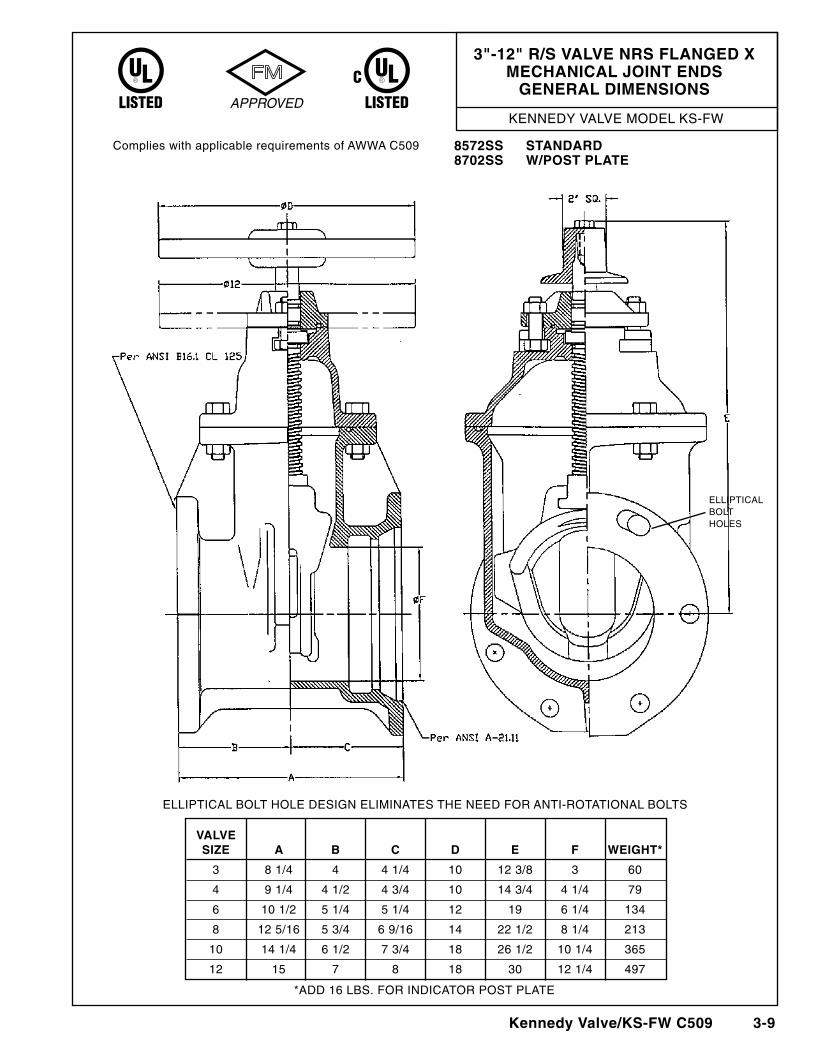
3"-12" R/S VALVE NRS FLANGED x MECHANICAL JOINT ENDS
GENERAL DIMENSIONS
Complies with applicable requirements of AWWA C509 8572SS STANDARD8702SS W/POST PLATE
ELLIPTICAL BOLT HOLE DESIGN ELIMINATES THE NEED FOR ANTI-ROTATIONAL BOLTS
ELLIPTICALBOLTHOLES
VALVE SIZE A b C D E F WEIGHT*
3 8 1/4 4 4 1/4 10 12 3/8 3 60
4 9 1/4 4 1/2 4 3/4 10 14 3/4 4 1/4 79
6 10 1/2 5 1/4 5 1/4 12 19 6 1/4 134
8 12 5/16 5 3/4 6 9/16 14 22 1/2 8 1/4 213
10 14 1/4 6 1/2 7 3/4 18 26 1/2 10 1/4 365
12 15 7 8 18 30 12 1/4 497
*ADD 16 LBS. FOR INDICATOR POST PLATE
KENNEDY VALVE MODEL KS-FW
3-10 Kennedy Valve/KS-FW C509
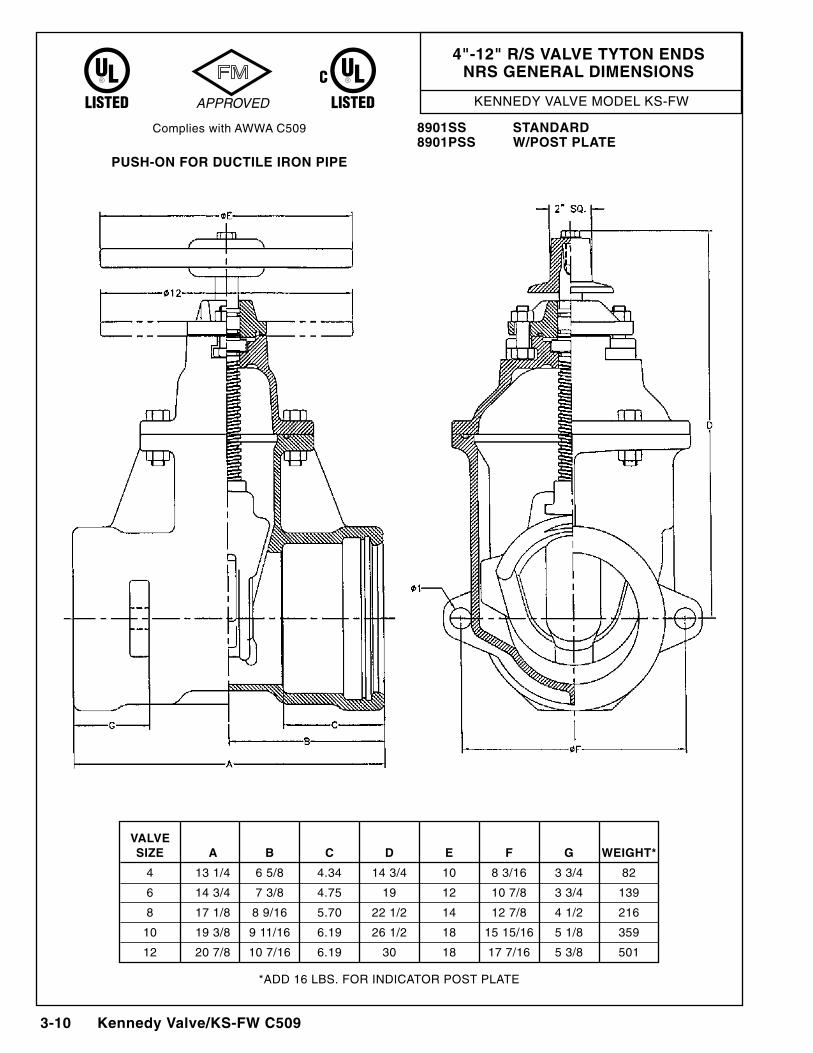
4"-12" R/S VALVE TYTON ENDSNRS GENERAL DIMENSIONS
Complies with AWWA C509 8901SS STANDARD8901PSS W/POST PLATE
PUSH-ON FOR DUCTILE IRON PIPE
VALVE SIZE A b C D E F G WEIGHT*
4 13 1/4 6 5/8 4.34 14 3/4 10 8 3/16 3 3/4 82
6 14 3/4 7 3/8 4.75 19 12 10 7/8 3 3/4 139
8 17 1/8 8 9/16 5.70 22 1/2 14 12 7/8 4 1/2 216
10 19 3/8 9 11/16 6.19 26 1/2 18 15 15/16 5 1/8 359
12 20 7/8 10 7/16 6.19 30 18 17 7/16 5 3/8 501
*ADD 16 LBS. FOR INDICATOR POST PLATE
KENNEDY VALVE MODEL KS-FW
Kennedy Valve/KS-FW C509 3- 11
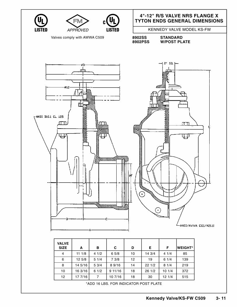
4"-12" R/S VALVE NRS FLANGE xTYTON ENDS GENERAL DIMENSIONS
Valves comply with AWWA C509 8902SS STANDARD8902PSS W/POST PLATE
VALVE SIZE A b C D E F WEIGHT*
4 11 1/8 4 1/2 6 5/8 10 14 3/4 4 1/4 85
6 12 5/8 5 1/4 7 3/8 12 19 6 1/4 139
8 14 5/16 5 3/4 8 9/16 14 22 1/2 8 1/4 219
10 16 3/16 6 1/2 9 11/16 18 26 1/2 10 1/4 372
12 17 7/16 7 10 7/16 18 30 12 1/4 515
*ADD 16 LBS. FOR INDICATOR POST PLATE
KENNEDY VALVE MODEL KS-FW
3-12 Kennedy Valve/KS-FW C509
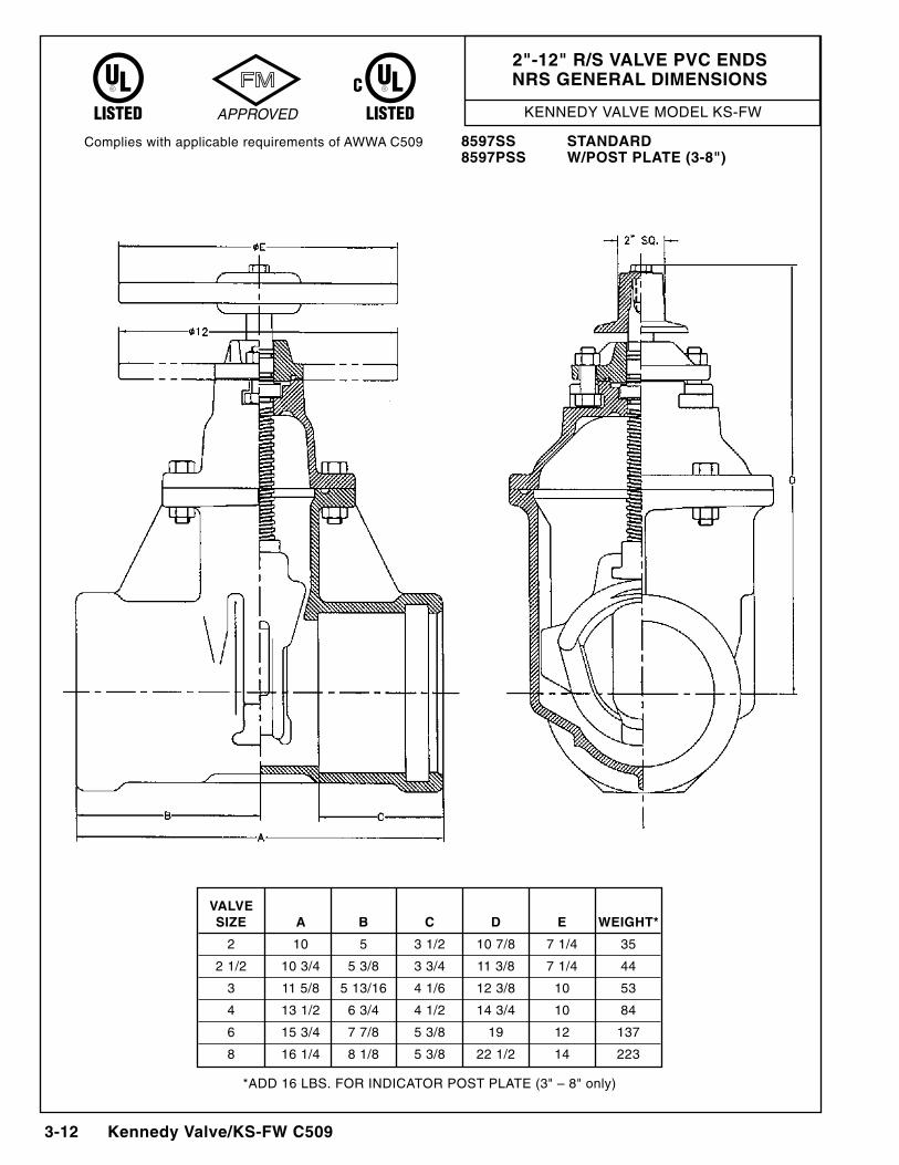
2"-12" R/S VALVE PVC ENDSNRS GENERAL DIMENSIONS
Complies with applicable requirements of AWWA C509 8597SS STANDARD8597PSS W/POST PLATE (3-8")
VALVE SIZE A b C D E WEIGHT*
2 10 5 3 1/2 10 7/8 7 1/4 35
2 1/2 10 3/4 5 3/8 3 3/4 11 3/8 7 1/4 44
3 11 5/8 5 13/16 4 1/6 12 3/8 10 53
4 13 1/2 6 3/4 4 1/2 14 3/4 10 84
6 15 3/4 7 7/8 5 3/8 19 12 137
8 16 1/4 8 1/8 5 3/8 22 1/2 14 223
*ADD 16 LBS. FOR INDICATOR POST PLATE (3" – 8" only)
KENNEDY VALVE MODEL KS-FW
Kennedy Valve/KS-FW C509 3- 13
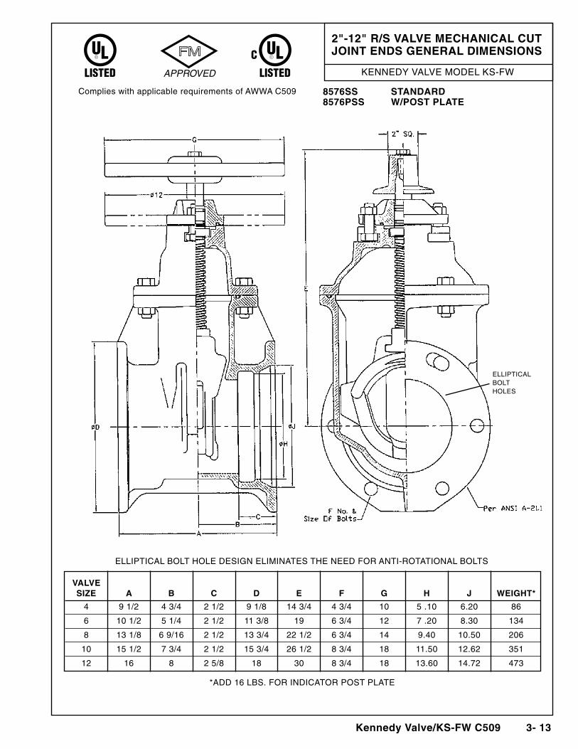
2"-12" R/S VALVE MECHANICAL CUTJOINT ENDS GENERAL DIMENSIONS
Complies with applicable requirements of AWWA C509 8576SS STANDARD8576PSS W/POST PLATE
ELLIPTICAL BOLT HOLE DESIGN ELIMINATES THE NEED FOR ANTI-ROTATIONAL BOLTS
ELLIPTICALBOLTHOLES
VALVE SIZE A b C D E F G H J WEIGHT*
4 9 1/2 4 3/4 2 1/2 9 1/8 14 3/4 4 3/4 10 5 .10 6.20 86
6 10 1/2 5 1/4 2 1/2 11 3/8 19 6 3/4 12 7 .20 8.30 134
8 13 1/8 6 9/16 2 1/2 13 3/4 22 1/2 6 3/4 14 9.40 10.50 206
10 15 1/2 7 3/4 2 1/2 15 3/4 26 1/2 8 3/4 18 11.50 12.62 351
12 16 8 2 5/8 18 30 8 3/4 18 13.60 14.72 473
*ADD 16 LBS. FOR INDICATOR POST PLATE
KENNEDY VALVE MODEL KS-FW
3-14 Kennedy Valve/KS-FW C509
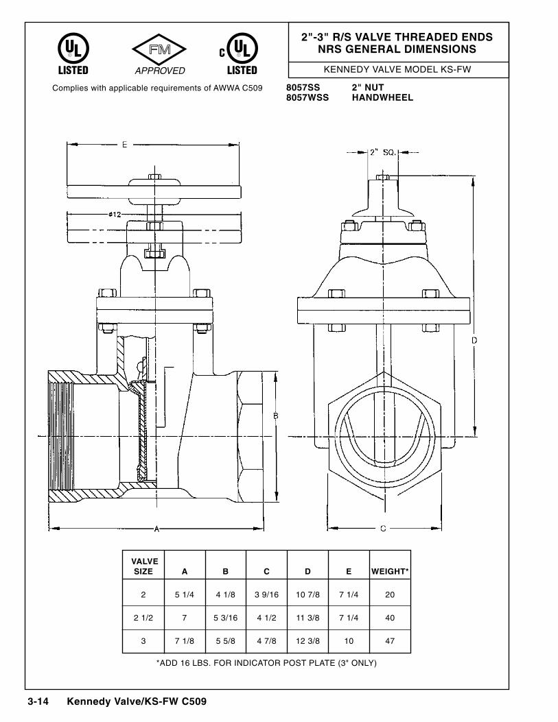
2"-3" R/S VALVE THREADED ENDSNRS GENERAL DIMENSIONS
Complies with applicable requirements of AWWA C509 8057SS 2" NUT8057WSS HANDWHEEL
VALVE SIZE A b C D E WEIGHT*
2 5 1/4 4 1/8 3 9/16 10 7/8 7 1/4 20
2 1/2 7 5 3/16 4 1/2 11 3/8 7 1/4 40
3 7 1/8 5 5/8 4 7/8 12 3/8 10 47
*ADD 16 LBS. FOR INDICATOR POST PLATE (3" ONLY)
Kennedy Valve/KS-FW C509 3-15
KENNEDY VALVE MODEL KS-FW
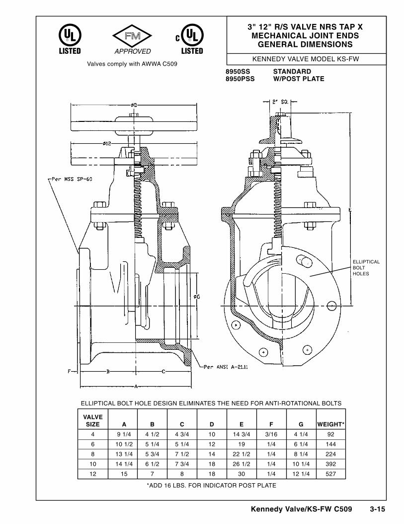
3" 12" R/S VALVE NRS TAP xMECHANICAL JOINT ENDS
GENERAL DIMENSIONS
Valves comply with AWWA C5098950SS STANDARD8950PSS W/POST PLATE
ELLIPTICAL BOLT HOLE DESIGN ELIMINATES THE NEED FOR ANTI-ROTATIONAL BOLTS
ELLIPTICALBOLTHOLES
VALVE SIZE A b C D E F G WEIGHT*
4 9 1/4 4 1/2 4 3/4 10 14 3/4 3/16 4 1/4 92
6 10 1/2 5 1/4 5 1/4 12 19 1/4 6 1/4 144
8 13 1/4 5 3/4 7 1/2 14 22 1/2 1/4 8 1/4 224
10 14 1/4 6 1/2 7 3/4 18 26 1/2 1/4 10 1/4 392
12 15 7 8 18 30 1/4 12 1/4 527
*ADD 16 LBS. FOR INDICATOR POST PLATE
KENNEDY VALVE MODEL KS-FW
3-16 Kennedy Valve/KS-FW C509
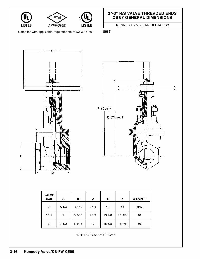
2"-3" R/S VALVE THREADED ENDSOS&Y GENERAL DIMENSIONS
Complies with applicable requirements of AWWA C509 8067
*NOTE: 2" size not UL listed
VALVE SIZE A b D E F WEIGHT*
2 5 1/4 4 1/8 7 1/4 12 10 N/A
2 1/2 7 5 3/16 7 1/4 13 7/8 16 3/8 40
3 7 1/2 5 3/16 10 15 5/8 18 7/8 50
Kennedy Valve/Indicator Posts 17-1
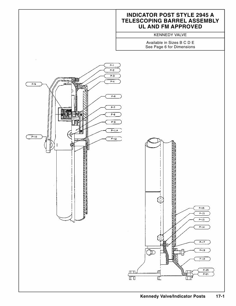
IndIcator Post style 2945 a telescoPIng Barrel assemBly
Ul and Fm aPProVedKennedy ValVe
available in Sizes B C d eSee Page 6 for dimensions
17-2 Kennedy Valve/Indicator Posts
46 3/4"
1 1/4" sq.
1" sq. stem
9"
36 3/4"
5 1/8"
30"
10"
12" dia.
trenchdepth
Kennedy
ground line
telescopingBarrel
top section6" dia.max. = 10"min. = 7"
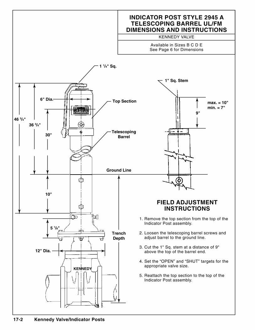
IndIcator Post style 2945 a telescoPIng Barrel Ul/Fm
dImensIons and InstrUctIonsKennedy ValVe
available in Sizes B C d eSee Page 6 for dimensions
FIeld adjUstment InstrUctIons
1. Remove the top section from the top of the Indicator Post assembly.
2. loosen the telescoping barrel screws and adjust barrel to the ground line.
3. Cut the 1" Sq. stem at a distance of 9" above the top of the barrel end.
4. Set the “OPen” and “SHUT” targets for the appropriate valve size.
5. Reattach the top section to the top of the Indicator Post assembly.
Kennedy Valve/Indicator Posts 17-3
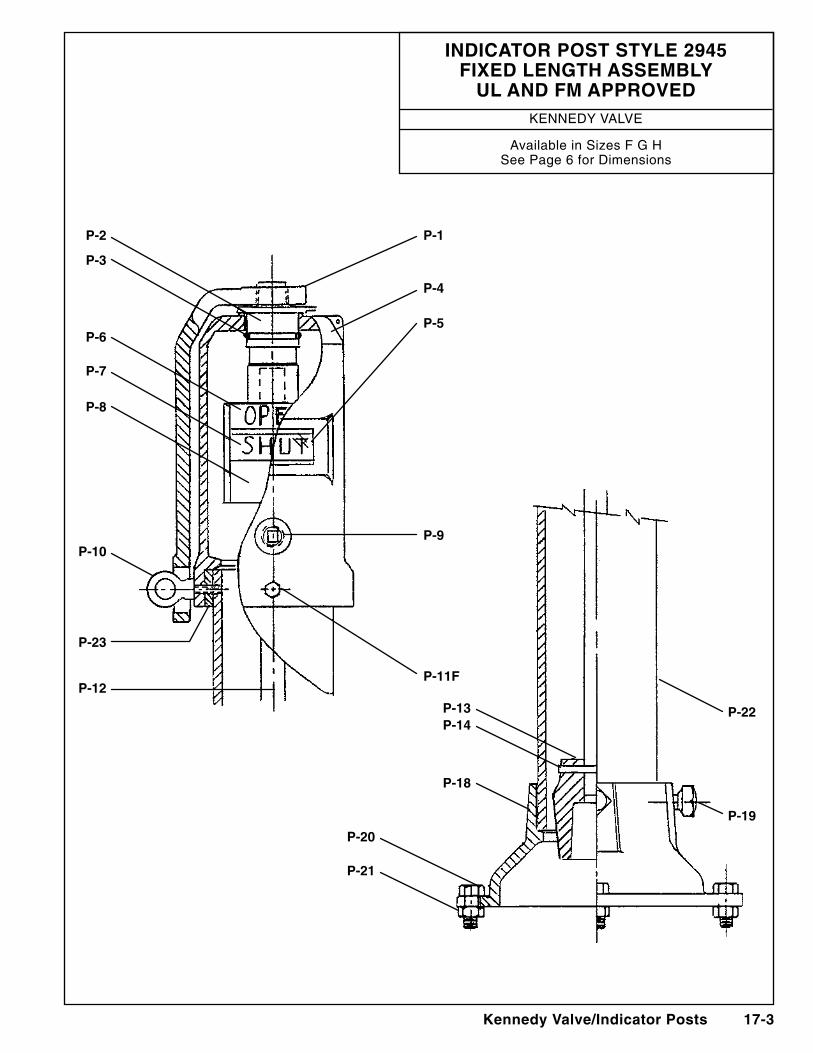
P-2 P-1
P-4
P-5
P-9
P-11F
P-22
P-19
P-3
P-6
P-7
P-8
P-10
P-13P-14
P-18
P-20
P-21
P-23
P-12
IndIcator Post style 2945 FIxed length assemBly
Ul and Fm aPProVedKennedy ValVe
available in Sizes F G HSee Page 6 for dimensions
17-4 Kennedy Valve/Indicator Posts
1 1/4" sq.
1" sq. stem
9"
36 3/4"
5 1/8"
30"
6" dia.
12" dia.
trenchdepth
Kennedy
ground line
standpipe(painted red)
standpipe(painted black)
top sectionmax. = 10"min. = 7"
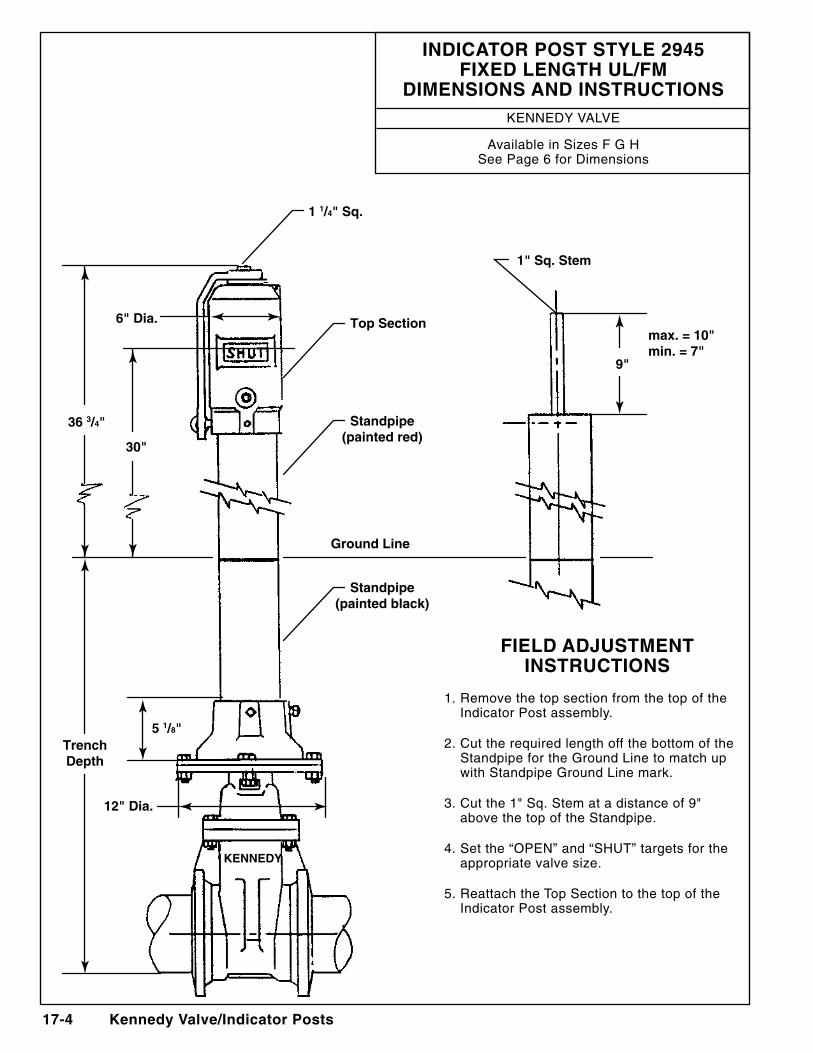
IndIcator Post style 2945 FIxed length Ul/Fm
dImensIons and InstrUctIonsKennedy ValVe
available in Sizes F G HSee Page 6 for dimensions
FIeld adjUstment InstrUctIons
1. Remove the top section from the top of the Indicator Post assembly.
2. Cut the required length off the bottom of the Standpipe for the Ground line to match up with Standpipe Ground line mark.
3. Cut the 1" Sq. Stem at a distance of 9" above the top of the Standpipe.
4. Set the “OPen” and “SHUT” targets for the appropriate valve size.
5. Reattach the Top Section to the top of the Indicator Post assembly.
Kennedy Valve/Indicator Posts 17-5
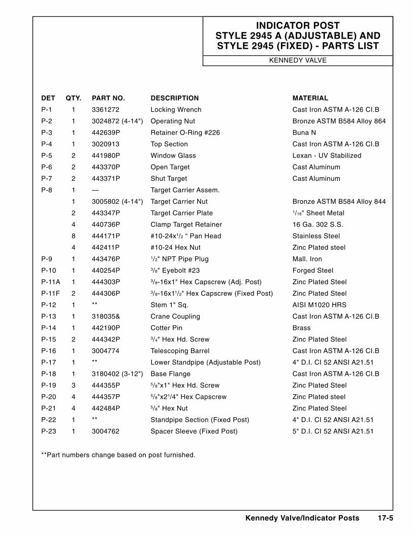
IndIcator Post style 2945 a (adjUstaBle) and style 2945 (FIxed) - Parts lIst
Kennedy ValVe
det Qty. Part no. descrIPtIon materIal
P-1 1 3361272 locking Wrench Cast Iron aSTM a-126 CI.B
P-2 1 3024872 (4-14") Operating nut Bronze aSTM B584 alloy 864
P-3 1 442639P Retainer O-Ring #226 Buna n
P-4 1 3020913 Top Section Cast Iron aSTM a-126 CI.B
P-5 2 441980P Window Glass lexan - UV Stabilized
P-6 2 443370P Open Target Cast aluminum
P-7 2 443371P Shut Target Cast aluminum
P-8 1 — Target Carrier assem.
1 3005802 (4-14") Target Carrier nut Bronze aSTM B584 alloy 844
2 443347P Target Carrier Plate 1/16" Sheet Metal
4 440736P Clamp Target Retainer 16 Ga. 302 S.S.
8 444171P #10-24x1/2 “ Pan Head Stainless Steel
4 442411P #10-24 Hex nut Zinc Plated steel
P-9 1 443476P 1/2" nPT Pipe Plug Mall. Iron
P-10 1 440254P 3/8" eyebolt #23 Forged Steel
P-11a 1 444303P 3/8-16x1" Hex Capscrew (adj. Post) Zinc Plated Steel
P-11F 2 444306P 3/8-16x11/2" Hex Capscrew (Fixed Post) Zinc Plated Steel
P-12 1 ** Stem 1" Sq. aISI M1020 HRS
P-13 1 318035& Crane Coupling Cast Iron aSTM a-126 CI.B
P-14 1 442190P Cotter Pin Brass
P-15 2 444342P 3/4" Hex Hd. Screw Zinc Plated Steel
P-16 1 3004774 Telescoping Barrel Cast Iron aSTM a-126 CI.B
P-17 1 ** lower Standpipe (adjustable Post) 4" d.I. CI 52 anSI a21.51
P-18 1 3180402 (3-12") Base Flange Cast Iron aSTM a-126 CI.B
P-19 3 444355P 5/8"x1" Hex Hd. Screw Zinc Plated Steel
P-20 4 444357P 5/8"x21/4" Hex Capscrew Zinc Plated steel
P-21 4 442484P 5/8" Hex nut Zinc Plated Steel
P-22 1 ** Standpipe Section (Fixed Post) 4" d.I. CI 52 anSI a21.51
P-23 1 3004762 Spacer Sleeve (Fixed Post) 5" d.I. CI 52 anSI a21.51
**Part numbers change based on post furnished.
17-6 Kennedy Valve/Indicator Posts
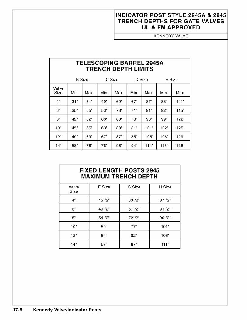
FIxed length Posts 2945 maxImUm trench dePth
Valve F Size G Size H Size Size
4" 451/2" 631/2" 871/2"
6" 491/2" 671/2" 911/2"
8" 541/2" 721/2" 961/2"
10" 59" 77" 101"
12" 64" 82" 106"
14" 69" 87" 111"
telescoPIng Barrel 2945a trench dePth lImIts
B Size C Size d Size e Size
Valve Size Min. Max. Min. Max. Min. Max. Min. Max.
4" 31" 51" 49" 69" 67" 87" 88" 111"
6" 35" 55" 53" 73" 71" 91" 92" 115"
8" 42" 62" 60" 80" 78" 98" 99" 122"
10" 45" 65" 63" 83" 81" 101" 102" 125"
12" 49" 69" 67" 87" 85" 105" 106" 129"
14" 58" 78" 76" 96" 94" 114" 115" 138"
IndIcator Post style 2945a & 2945 trench dePths For gate ValVes
Ul & Fm aPProVedKennedy ValVe
Kennedy Valve/Indicator Posts 17-7
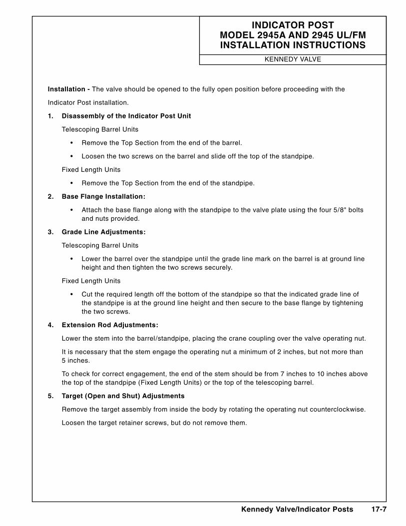
IndIcator Post model 2945a and 2945 Ul/Fm InstallatIon InstrUctIons
Kennedy ValVe
Installation - The valve should be opened to the fully open position before proceeding with the
Indicator Post installation.
1. disassembly of the Indicator Post Unit
Telescoping Barrel Units
• RemovetheTopSectionfromtheendofthebarrel.
• Loosenthetwoscrewsonthebarrelandslideoffthetopofthestandpipe.
Fixed length Units
• RemovetheTopSectionfromtheendofthestandpipe.
2. Base Flange Installation:
• Attachthebaseflangealongwiththestandpipetothevalveplateusingthefour5/8"boltsand nuts provided.
3. grade line adjustments:
Telescoping Barrel Units
• Lowerthebarreloverthestandpipeuntilthegradelinemarkonthebarrelisatgroundlineheight and then tighten the two screws securely.
Fixed length Units
• Cuttherequiredlengthoffthebottomofthestandpipesothattheindicatedgradelineof the standpipe is at the ground line height and then secure to the base flange by tightening the two screws.
4. extension rod adjustments:
lower the stem into the barrel/standpipe, placing the crane coupling over the valve operating nut.
It is necessary that the stem engage the operating nut a minimum of 2 inches, but not more than 5 inches.
To check for correct engagement, the end of the stem should be from 7 inches to 10 inches above the top of the standpipe (Fixed length Units) or the top of the telescoping barrel.
5. target (open and shut) adjustments
Remove the target assembly from inside the body by rotating the operating nut counterclockwise.
loosen the target retainer screws, but do not remove them.
17-8 Kennedy Valve/Indicator Posts
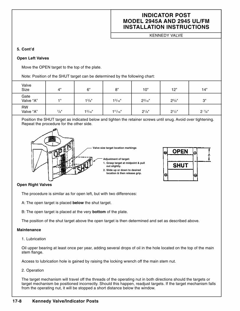
5. cont’d
open left Valves
Move the OPen target to the top of the plate.
note: Position of the SHUT target can be determined by the following chart:
Valve Size 4" 6" 8" 10" 12" 14"
Gate Valve “a” 1" 13/8" 13/16" 23/16" 25/8" 3"
RW Valve “a” 7/8" 15/16" 111/16" 21/8" 21/2" 2 7/8"
Position the SHUT target as indicated below and tighten the retainer screws until snug. avoid over tightening. Repeat the procedure for the other side.
open right Valves
The procedure is similar as for open left, but with two differences:
a: The open target is placed below the shut target.
B: The open target is placed at the very bottom of the plate.
The position of the shut target above the open target is then determined and set as described above.
maintenance
1. lubrication
Oil upper bearing at least once per year, adding several drops of oil in the hole located on the top of the main stem flange.
access to lubrication hole is gained by raising the locking wrench off the main stem nut.
2. Operation
The target mechanism will travel off the threads of the operating nut in both directions should the targets or target mechanism be positioned incorrectly. Should this happen, readjust targets. If the target mechanism falls from the operating nut, it will be stopped a short distance below the window.
IndIcator Post model 2945a and 2945 Ul/Fm InstallatIon InstrUctIons
Kennedy ValVe
45
6
19 16
Valve size target location markings
adjustment of target:
1. grasp target at midpoint & pull out slightly.
2. slide up or down to desired location & then release grip.
Kennedy Valve/Indicator Posts 17-9
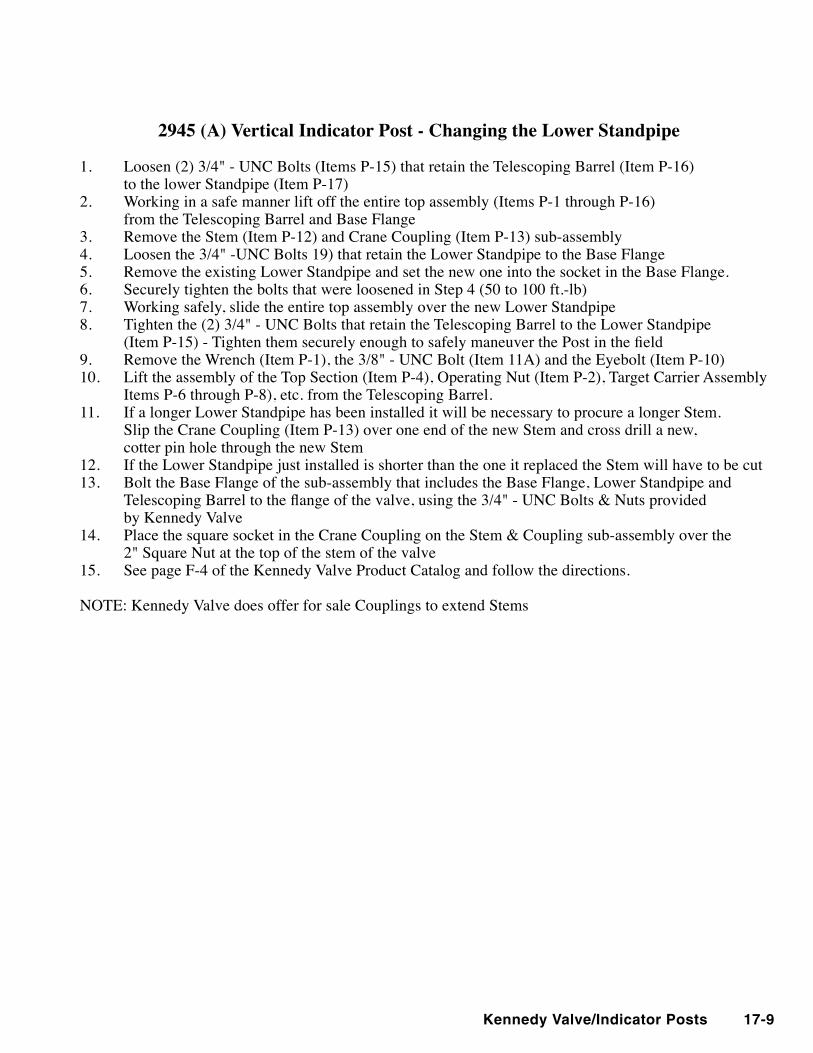
2945 (A) Vertical Indicator Post - Changing the Lower Standpipe
1. Loosen (2) 3/4" - UNC Bolts (Items P-15) that retain the Telescoping Barrel (Item P-16) to the lower Standpipe (Item P-17)2. Working in a safe manner lift off the entire top assembly (Items P-1 through P-16) from the Telescoping Barrel and Base Flange3. Remove the Stem (Item P-12) and Crane Coupling (Item P-13) sub-assembly4. Loosen the 3/4" -UNC Bolts 19) that retain the Lower Standpipe to the Base Flange5. Remove the existing Lower Standpipe and set the new one into the socket in the Base Flange.6. Securely tighten the bolts that were loosened in Step 4 (50 to 100 ft.-lb)7. Working safely, slide the entire top assembly over the new Lower Standpipe8. Tighten the (2) 3/4" - UNC Bolts that retain the Telescoping Barrel to the Lower Standpipe (ItemP-15)-TightenthemsecurelyenoughtosafelymaneuverthePostinthefield9. Remove the Wrench (Item P-1), the 3/8" - UNC Bolt (Item 11A) and the Eyebolt (Item P-10)10. Lift the assembly of the Top Section (Item P-4), Operating Nut (Item P-2), Target Carrier Assembly
Items P-6 through P-8), etc. from the Telescoping Barrel. 11. If a longer Lower Standpipe has been installed it will be necessary to procure a longer Stem. Slip the Crane Coupling (Item P-13) over one end of the new Stem and cross drill a new, cotter pin hole through the new Stem12. If the Lower Standpipe just installed is shorter than the one it replaced the Stem will have to be cut13. Bolt the Base Flange of the sub-assembly that includes the Base Flange, Lower Standpipe and TelescopingBarreltotheflangeofthevalve,usingthe3/4"-UNCBolts&Nutsprovided by Kennedy Valve14. PlacethesquaresocketintheCraneCouplingontheStem&Couplingsub-assemblyoverthe 2" Square Nut at the top of the stem of the valve15. See page F-4 of the Kennedy Valve Product Catalog and follow the directions.
NOTE: Kennedy Valve does offer for sale Couplings to extend Stems
17-10 Kennedy Valve/Indicator Posts
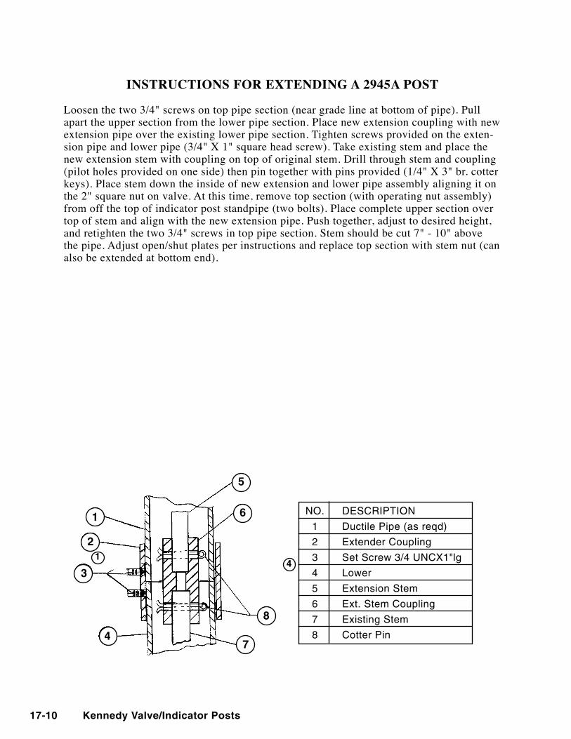
INSTRUCTIONS FOR EXTENDING A 2945A POST
Loosen the two 3/4" screws on top pipe section (near grade line at bottom of pipe). Pull apart the upper section from the lower pipe section. Place new extension coupling with new extension pipe over the existing lower pipe section. Tighten screws provided on the exten-sion pipe and lower pipe (3/4" X 1" square head screw). Take existing stem and place the new extension stem with coupling on top of original stem. Drill through stem and coupling (pilot holes provided on one side) then pin together with pins provided (1/4" X 3" br. cotter keys). Place stem down the inside of new extension and lower pipe assembly aligning it on the 2" square nut on valve. At this time, remove top section (with operating nut assembly) from off the top of indicator post standpipe (two bolts). Place complete upper section over top of stem and align with the new extension pipe. Push together, adjust to desired height, and retighten the two 3/4" screws in top pipe section. Stem should be cut 7" - 10" above the pipe. Adjust open/shut plates per instructions and replace top section with stem nut (can also be extended at bottom end).
1
2
3
4
5
6
8
7
14
nO. deSCRIPTIOn
1 ductile Pipe (as reqd)
2 extender Coupling
3 Set Screw 3/4 UnCX1"lg
4 lower
5 extension Stem
6 ext. Stem Coupling
7 existing Stem
8 Cotter Pin
Kennedy Valve/Indicator Posts 17-11
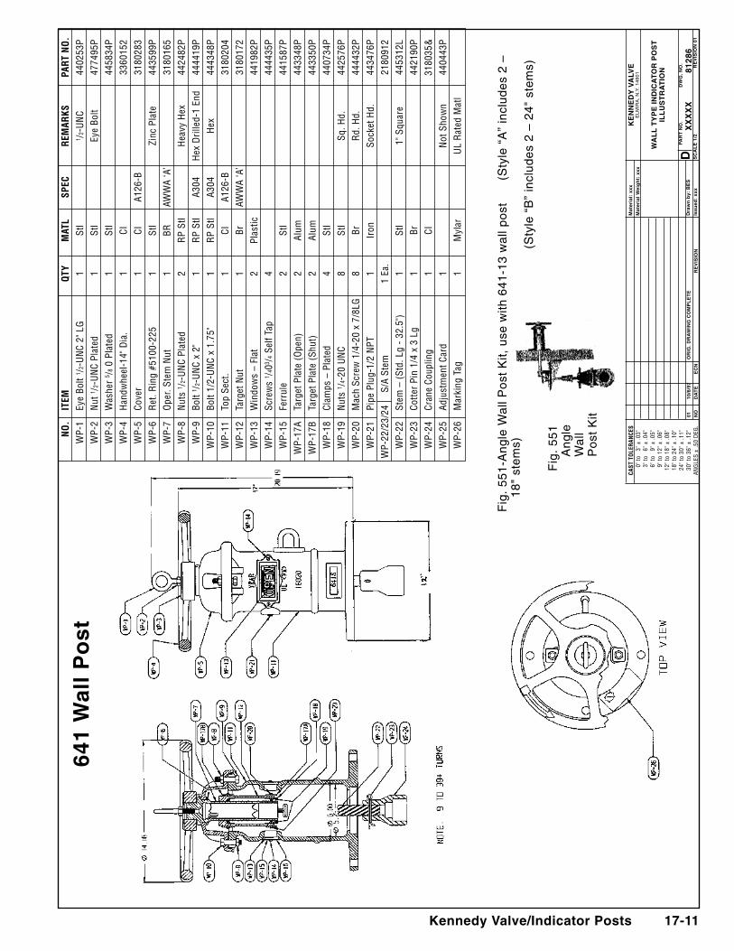
641
Wal
l P
ost
Fig
. 5
51
-an
gle
Wa
ll P
ost
Kit,
use
with
64
1-1
3 w
all
po
st
(Sty
le “
a”
incl
ud
es
2 –
1
8"
ste
ms)
(Sty
le “
B”
incl
ud
es
2 –
24
" st
em
s)
Fig
. 5
51
an
gle
W
all
Po
st K
it
CAST
TO
LER
ANCE
S 0
" to
3" ±
.03"
3" t
o 6
" ± .0
4" 6
" to
9" ±
.05"
9" t
o 12
" ± .0
6"12
" to
18" ±
.08"
18" t
o 24
" ± .1
0"24
" to
30" ±
.11"
30" t
o 36
" ± .1
2"AN
GLE
S ±
.50
DEG
.
Ke
nn
ed
y V
alV
ee
lM
IRa
, n
.y.
14
90
1
Wa
ll
ty
Pe
In
dIc
at
or
Po
st
Ill
Us
tr
at
Ion
Pa
rt
no
. d
Wg
. n
o.
x
xx
xx
8128
6s
ca
le
1/2
re
VIs
Ion
01
mat
eria
l: x
xx
mat
eria
l W
eig
ht:
xxx
dra
wn
by:
Be
s
Issu
ed:
xxx
or
Ig.
dr
aW
Ing
co
mP
le
te
r
eV
IsIo
n
01
10/6
/97
no
d
at
e
ec
n
N
O.
ITEM
Q
TY
MAT
L SP
EC
REM
ARKS
PA
RT N
O.
W
P-1
Eye
Bolt
1 /2-U
NC
2" L
G
1 St
l
1 /2-U
NC
4402
53P
W
P-2
Nut
1 /2-U
NC
Plat
ed
1 St
l
Eye
Bolt
4774
95P
W
P-3
Was
her
5 /8 0
Pla
ted
1 St
l
44
5834
P
WP-
4 H
andw
heel
-14"
Dia
. 1
CI
3360
152
W
P-5
Cove
r 1
CI
A126
-B
31
8028
3
WP-
6 R
et. R
ing
#510
0-22
5 1
Stl
Zi
nc P
late
44
3599
P
WP-
7 O
per.
Stem
Nut
1
BR
AWW
A ‘A
’
3180
165
W
P-8
Nut
s 1 /2
-UN
C Pl
ated
2
RP
Stl
H
eavy
Hex
44
2482
P
WP-
9 Bo
lt 1 /2
-UN
C x
2"
1 R
P St
l A3
04
Hex
Dril
led-
1 En
d 44
4419
P
WP-
10
Bolt
1/2-
UN
C x
1.75
" 1
RP
Stl
A304
H
ex
4443
48P
W
P-11
To
p Se
ct.
1 CI
A1
26-B
3180
204
W
P-12
Ta
rget
Nut
1
Br
AWW
A ‘A
’
3180
172
W
P-13
W
indo
ws
– Fl
at
2 Pl
astic
44
1982
P
WP-
14
Scre
ws
1 /403 /4
Sel
f Tap
4
44
4435
P
WP-
15
Ferr
ule
2 St
l
44
1587
P
WP-
17A
Targ
et P
late
(O
pen)
2
Alum
44
3348
P
WP-
17B
Targ
et P
late
(Sh
ut)
2 Al
um
4433
50P
W
P-18
Cl
amps
– P
late
d 4
Stl
4407
34P
W
P-19
N
uts
1 /4-2
0 U
NC
8 St
l
Sq. H
d.
4425
76P
W
P-20
M
ach
Scre
w 1
/4-2
0 x
7/8L
G
8 Br
Rd.
Hd.
44
4432
P
WP-
21
Pipe
Plu
g-1/
2 N
PT
1 Ir
on
So
cket
Hd.
44
3476
P W
P-22
/23/
24
S/A
Stem
1
Ea.
21
8091
2
WP-
22
Stem
– (
Std.
Lg
- 32
.5")
1
Stl
1"
Squ
are
4453
12L
W
P-23
Co
tter
Pin
1/4
x 3
Lg
1 Br
44
2190
P
WP-
24
Cran
e Co
uplin
g 1
CI
3180
35&
W
P-25
Ad
just
men
t Car
d 1
Not
Sho
wn
4404
43P
W
P-26
M
arki
ng T
ag
1 M
ylar
UL
Rat
ed M
atl
17-12 Kennedy Valve/Indicator Posts
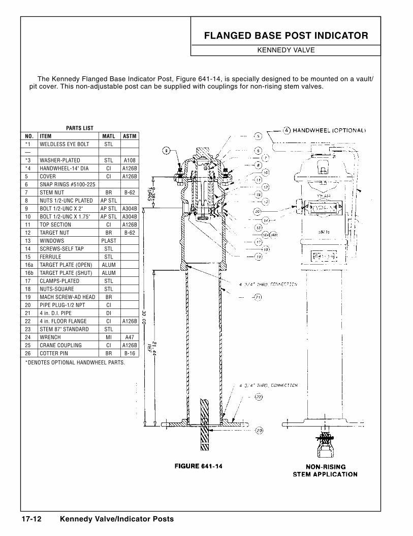
Flanged Base Post IndIcatorKennedy ValVe
The Kennedy Flanged Base Indicator Post, Figure 641-14, is specially designed to be mounted on a vault/pit cover. This non-adjustable post can be supplied with couplings for non-rising stem valves.
PARTS LIST NO. ITEM MATL ASTM *1 WELDLESS EYE BOLT STL — *3 WASHER-PLATED STL A108 *4 HANDWHEEL-14" DIA CI A126B 5 COVER CI A126B 6 SNAP RINGS #5100-225 7 STEM NUT BR B-62 8 NUTS 1/2-UNC PLATED AP STL 9 BOLT 1/2-UNC X 2" AP STL A304B 10 BOLT 1/2-UNC X 1.75" AP STL A304B 11 TOP SECTION CI A126B 12 TARGET NUT BR B-62 13 WINDOWS PLAST 14 SCREWS-SELF TAP STL 15 FERRULE STL 16a TARGET PLATE (OPEN) ALUM 16b TARGET PLATE (SHUT) ALUM 17 CLAMPS-PLATED STL 18 NUTS-SQUARE STL 19 MACH SCREW-AD HEAD BR 20 PIPE PLUG-1/2 NPT CI 21 4 in. D.I. PIPE DI 22 4 in. FLOOR FLANGE CI A126B 23 STEM 87" STANDARD STL 24 WRENCH MI A47 25 CRANE COUPLING CI A126B 26 COTTER PIN BR B-16
*DENOTES OPTIONAL HANDWHEEL PARTS.