Embed Size (px)
Citation preview
INDUCTION 6J – 1
INDUCTIONCONTENTS
General Description . . . . . . . . . . . . . . . . . . 6J–2
Air Cleaner . . . . . . . . . . . . . . . . . . . . . . . . . 6J–3
Turbocharger . . . . . . . . . . . . . . . . . . . . . . . 6J–4
Intercooler . . . . . . . . . . . . . . . . . . . . . . . . . 6J–9
Intake Throttle Valve . . . . . . . . . . . . . . . . . . 6J–10
Intake Manifold . . . . . . . . . . . . . . . . . . . . . . 6J–11
Main Data and Specifications . . . . . . . . . . . 6J–12
6J – 2 INDUCTION
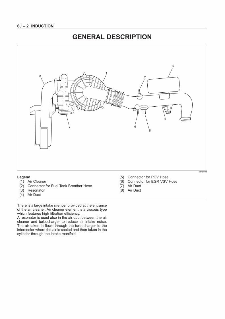
There is a large intake silencer provided at the entranceof the air cleaner. Air cleaner element is a viscous typewhich features high filtration efficiency.A resonator is used also in the air duct between the aircleaner and turbocharger to reduce air intake noise.The air taken in flows through the turbocharger to theintercooler where the air is cooled and then taken in thecylinder through the intake manifold.
7
1
2
3
4
8
5
6
Legend
(1) Air Cleaner
(2) Connector for Fuel Tank Breather Hose
(3) Resonator
(4) Air Duct
(5) Connector for PCV Hose
(6) Connector for EGR VSV Hose
(7) Air Duct
(8) Air Duct
130R200003
GENERAL DESCRIPTION
INDUCTION 6J – 3
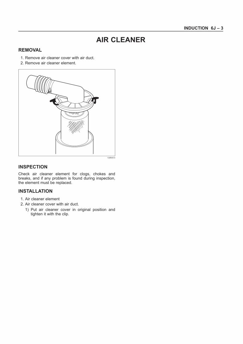
REMOVAL
1. Remove air cleaner cover with air duct.
2. Remove air cleaner element.
INSPECTION
Check air cleaner element for clogs, chokes andbreaks, and if any problem is found during inspection,the element must be replaced.
INSTALLATION
1. Air cleaner element
2. Air cleaner cover with air duct.
1) Put air cleaner cover in original position andtighten it with the clip.
130RW010
AIR CLEANER
6J – 4 INDUCTION
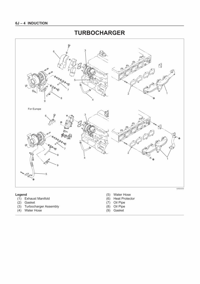
TURBOCHARGER
9
5
9
8
For Europe
8
7
5
6 3
2 1
4
7
4
2
1
36
Legend
(1) Exhaust Manifold
(2) Gasket
(3) Turbocharger Assembly
(4) Water Hose
(5) Water Hose
(6) Heat Protector
(7) Oil Pipe
(8) Oil Pipe
(9) Gasket
025R200004
INDUCTION 6J – 5
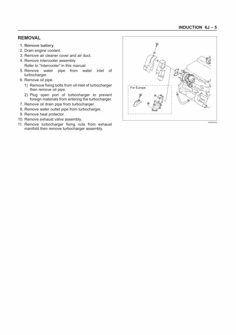
REMOVAL
1. Remove battery.2. Drain engine coolant.
3. Remove air cleaner cover and air duct.
4. Remove intercooler assembly.
Refer to “Intercooler” in this manual.
5. Remove water pipe from water inlet ofturbocharger.
6. Remove oil pipe.
1) Remove fixing bolts from oil inlet of turbochargerthen remove oil pipe.
2) Plug open port of turbocharger to preventforeign materials from entering the turbocharger.
7. Remove oil drain pipe from turbocharger.
8. Remove water outlet pipe from turbocharger.
9. Remove heat protector.
10. Remove exhaust valve assembly.
11. Remove turbocharger fixing nuts from exhaustmanifold then remove turbocharger assembly.
For Europe
025R200006
6J – 6 INDUCTION
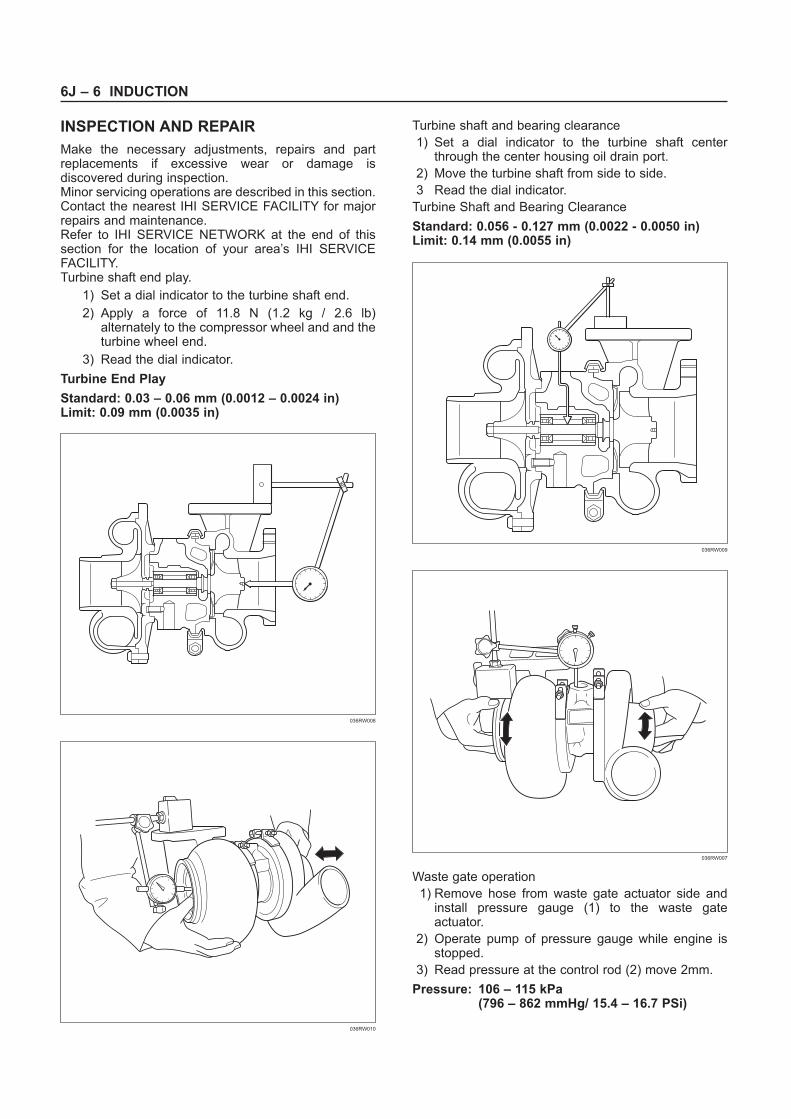
INSPECTION AND REPAIR
Make the necessary adjustments, repairs and partreplacements if excessive wear or damage isdiscovered during inspection.Minor servicing operations are described in this section.Contact the nearest IHI SERVICE FACILITY for majorrepairs and maintenance.Refer to IHI SERVICE NETWORK at the end of thissection for the location of your area’s IHI SERVICEFACILITY.Turbine shaft end play.
1) Set a dial indicator to the turbine shaft end.
2) Apply a force of 11.8 N (1.2 kg / 2.6 lb)alternately to the compressor wheel and and theturbine wheel end.
3) Read the dial indicator.
Turbine End Play
Standard: 0.03 – 0.06 mm (0.0012 – 0.0024 in)Limit: 0.09 mm (0.0035 in)
Turbine shaft and bearing clearance
1) Set a dial indicator to the turbine shaft centerthrough the center housing oil drain port.
2) Move the turbine shaft from side to side.
3 Read the dial indicator.
Turbine Shaft and Bearing Clearance
Standard: 0.056 - 0.127 mm (0.0022 - 0.0050 in)Limit: 0.14 mm (0.0055 in)
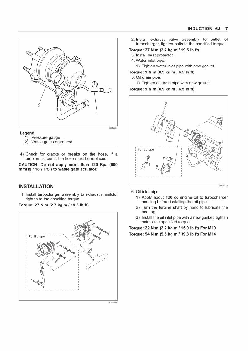
Waste gate operation
1) Remove hose from waste gate actuator side andinstall pressure gauge (1) to the waste gateactuator.
2) Operate pump of pressure gauge while engine isstopped.
3) Read pressure at the control rod (2) move 2mm.
Pressure: 106 – 115 kPa (796 – 862 mmHg/ 15.4 – 16.7 PSi)
036RW008
036RW010
036RW009
036RW007
INDUCTION 6J – 7
Legend(1) Pressure gauge(2) Waste gate control rod
4) Check for cracks or breaks on the hose, if aproblem is found, the hose must be replaced.
CAUTION: Do not apply more than 120 Kpa (900mmHg / 18.7 PSi) to waste gate actuator.
INSTALLATION
1. Install turbocharger assembly to exhaust manifold,tighten to the specified torque.
Torque: 27 N·m (2.7 kg·m / 19.5 lb ft)
2. Install exhaust valve assembly to outlet ofturbocharger, tighten bolts to the specified torque.
Torque: 27 N·m (2.7 kg·m / 19.5 lb ft)
3. Install heat protector.
4. Water inlet pipe.
1) Tighten water inlet pipe with new gasket.
Torque: 9 N·m (0.9 kg·m / 6.5 lb ft)
5. Oil drain pipe.
1) Tighten oil drain pipe with new gasket.
Torque: 9 N·m (0.9 kg·m / 6.5 lb ft)
6. Oil inlet pipe.
1) Apply about 100 cc engine oil to turbochargerhousing before installing the oil pipe.
2) Turn the turbine shaft by hand to lubricate thebearing.
3) Install the oil inlet pipe with a new gasket, tightenbolt to the specified torque.
Torque: 22 N·m (2.2 kg·m / 15.9 lb ft) For M10
Torque: 54 N·m (5.5 kg·m / 39.8 lb ft) For M14
2
1
036RW011
For Europe
025R200007
For Europe
025R200006
6J – 8 INDUCTION
7. Water inlet pipe.
1) Install water inlet pipe with a new gasket, tightenbolts to the specified torque.
Torque: 9 N·m (0.9 kg·m / 6.5 lb ft)
8. Install intercooler assembly.
Refer to “Intercooler” in this manual.
9. Install air cleaner cover with air duct.
10. Fill engine coolant to full level.
11. Install battery and connect battery cable.
For Europe
025R200007
INDUCTION 6J – 9
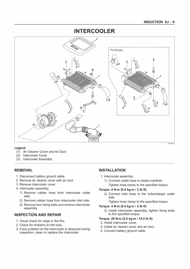
INTERCOOLER
REMOVAL
1. Disconnect battery ground cable.
2. Remove air cleaner cover with air duct.
3. Remove intercooler cover.
4. Intercooler assembly.
1) Remove rubber hose from intercooler outletside.
2) Remove rubber hose from intercooler inlet side.
3) Remove four fixing bolts and remove intercoolerassembly.
INSPECTION AND REPAIR
1. Visual check for clogs in the fins.
2. Check for brokens on the tube.
3. If any problem on the intercooler is observed duringinspection, clean or replace the intercooler.
INSTALLATION
1. Intercooler assembly.
1) Connect outlet hose to intake manifold.
Tighten hose clamp to the specified torque.
Torque: 4 N·m (0.4 kg·m / 3 lb ft)
2) Connect inlet hose to the turbocharger outletside.
Tighten hose clamp to the specified torque.
Torque: 4 N·m (0.4 kg·m / 3 lb ft)
3) Install intercooler assembly, tighten fixing boltsto the specified torque.
Torque: 20 N·m (2.0 kg·m / 14.5 lb ft)
2. Install intercooler cover.
3. Install air cleaner cover and air duct.
4. Connect battery ground cable.
For Europe
2
3 3
1
Legend
(1) Air Cleaner Cover and Air Duct
(2) Intercooler Cover
(3) Intercooler Assembly
135R200003
6J – 10 INDUCTION
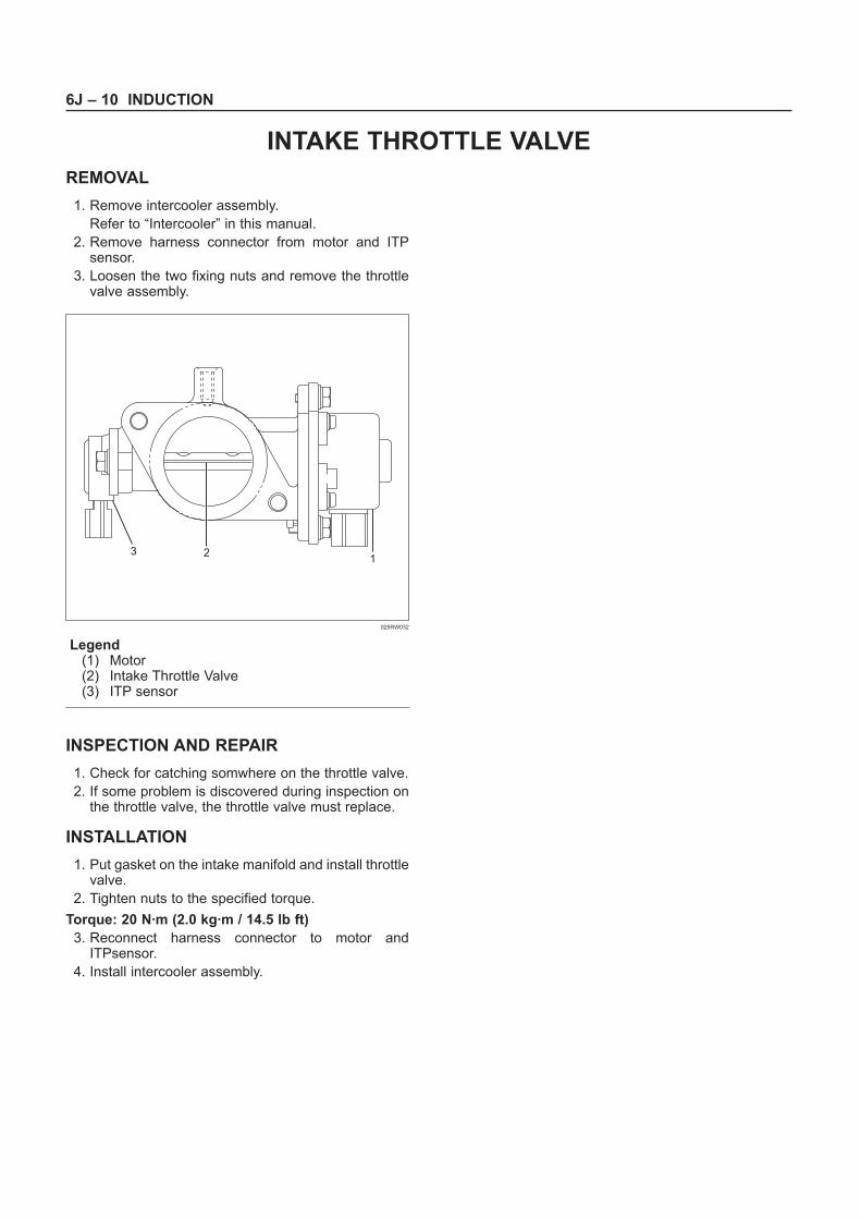
REMOVAL
1. Remove intercooler assembly.
Refer to “Intercooler” in this manual.
2. Remove harness connector from motor and ITPsensor.
3. Loosen the two fixing nuts and remove the throttlevalve assembly.
Legend(1) Motor(2) Intake Throttle Valve(3) ITP sensor
INSPECTION AND REPAIR
1. Check for catching somwhere on the throttle valve.
2. If some problem is discovered during inspection onthe throttle valve, the throttle valve must replace.
INSTALLATION
1. Put gasket on the intake manifold and install throttlevalve.
2. Tighten nuts to the specified torque.
Torque: 20 N·m (2.0 kg·m / 14.5 lb ft)
3. Reconnect harness connector to motor andITPsensor.
4. Install intercooler assembly.
123
025RW032
INTAKE THROTTLE VALVE
INDUCTION 6J – 11
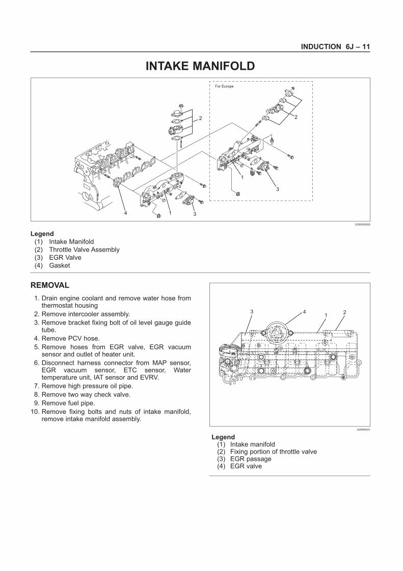
INTAKE MANIFOLD
REMOVAL
1. Drain engine coolant and remove water hose fromthermostat housing
2. Remove intercooler assembly.
3. Remove bracket fixing bolt of oil level gauge guidetube.
4. Remove PCV hose.
5. Remove hoses from EGR valve, EGR vacuumsensor and outlet of heater unit.
6. Disconnect harness connector from MAP sensor,EGR vacuum sensor, ETC sensor, Watertemperature unit, IAT sensor and EVRV.
7. Remove high pressure oil pipe.
8. Remove two way check valve.
9. Remove fuel pipe.
10. Remove fixing bolts and nuts of intake manifold,remove intake manifold assembly.
Legend(1) Intake manifold(2) Fixing portion of throttle valve(3) EGR passage(4) EGR valve
For Europe
2
1
3
314
2
Legend
(1) Intake Manifold
(2) Throttle Valve Assembly
(3) EGR Valve
(4) Gasket
025R200005
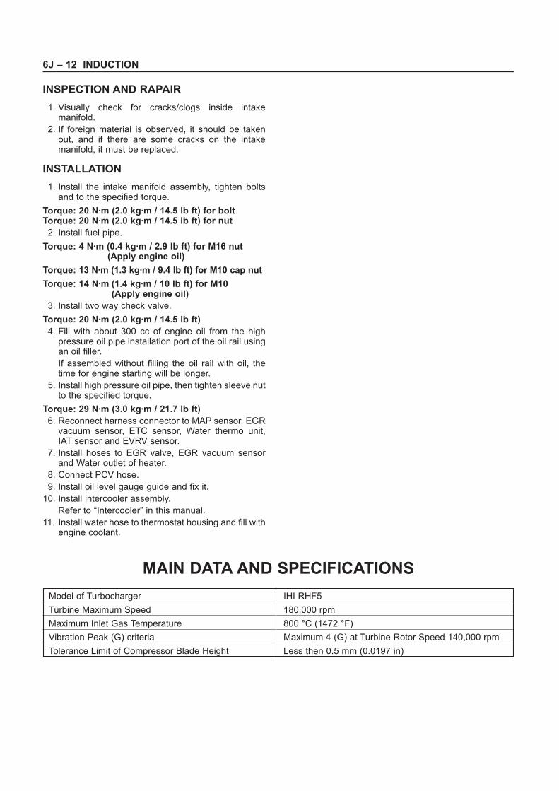
31
24
025RW031
6J – 12 INDUCTION
INSPECTION AND RAPAIR
1. Visually check for cracks/clogs inside intakemanifold.
2. If foreign material is observed, it should be takenout, and if there are some cracks on the intakemanifold, it must be replaced.
INSTALLATION
1. Install the intake manifold assembly, tighten boltsand to the specified torque.
Torque: 20 N·m (2.0 kg·m / 14.5 lb ft) for boltTorque: 20 N·m (2.0 kg·m / 14.5 lb ft) for nut
2. Install fuel pipe.
Torque: 4 N·m (0.4 kg·m / 2.9 lb ft) for M16 nut(Apply engine oil)
Torque: 13 N·m (1.3 kg·m / 9.4 lb ft) for M10 cap nut
Torque: 14 N·m (1.4 kg·m / 10 lb ft) for M10(Apply engine oil)
3. Install two way check valve.
Torque: 20 N·m (2.0 kg·m / 14.5 lb ft)
4. Fill with about 300 cc of engine oil from the highpressure oil pipe installation port of the oil rail usingan oil filler.
If assembled without filling the oil rail with oil, thetime for engine starting will be longer.
5. Install high pressure oil pipe, then tighten sleeve nutto the specified torque.
Torque: 29 N·m (3.0 kg·m / 21.7 lb ft)
6. Reconnect harness connector to MAP sensor, EGRvacuum sensor, ETC sensor, Water thermo unit,IAT sensor and EVRV sensor.
7. Install hoses to EGR valve, EGR vacuum sensorand Water outlet of heater.
8. Connect PCV hose.
9. Install oil level gauge guide and fix it.
10. Install intercooler assembly.
Refer to “Intercooler” in this manual.
11. Install water hose to thermostat housing and fill withengine coolant.
Model of Turbocharger IHI RHF5
Turbine Maximum Speed 180,000 rpm
Maximum Inlet Gas Temperature 800 °C (1472 °F)
Vibration Peak (G) criteria Maximum 4 (G) at Turbine Rotor Speed 140,000 rpm
Tolerance Limit of Compressor Blade Height Less then 0.5 mm (0.0197 in)
MAIN DATA AND SPECIFICATIONS