Embed Size (px)
Citation preview

NEON TECHNOLOGY
InternationalSpecialised Skills Institute Inc
ISS Institute Inc.FEBRUARY 2005 ©
John CraddockVictoria University/ISS Institute Fellowship
Fellowship funded by Victoria University (TAFE)
ISS Institute/TAFE Fellowship Neon Technology John Craddock
2
1.0 ACKNOWLEDGEMENTS I would like to acknowledge the ISS Institute for their support and guidance leading up to my Fellowship program, especially Carolynne Bourne for passing on her expertise and making her valuable time available to me. 1.2 FELLOWSHIP SPONSOR I would like to thank Victoria University senior management for their support and encouragement to apply for the ISS Fellowship, to be able to fill the “skills and knowledge” gap that exists with the Sign Industry. 1.3 PARTICIPANTS I would like to acknowledge the following companies and organisations for their support by allowing me to visit and exchange ideas and information and to be able to gain the necessary skills and knowledge required for my Fellowship program. Masonlite 36 Second Avenue Chatham Kent, England BSGA (British Sign and Graphics Association) 5 Orton Enterprise Centre Bakewell Road, Orton South Gate Peterborough Cambridgeshire, England Avenue Signs Ltd. 216-222 Luton Road Chatham Kent, England Kemps Neon Unit 2 Matrix Court Middleton Grove Leeds, England Hitech Signmakers Ltd. 65 Townsend Street Port Douglas Glasgow, Scotland AM Neon 28A Greenville Street Belfast, Northern Ireland
ISS Institute/TAFE Fellowship Neon Technology John Craddock
3
1.4 INDIVIDUAL AKNOWLWDGEMENTS I would like to thank Mark Vincent, Victorian President of the Victorian branch of the “Sign Association of Australia”, and Deidre Beck from “Beck Signage” for their support of my Fellowship application and identifying the skills gap within the Sign Industry. 2.0 INTRODUCTION 2.1 ISS INTRODUCTION The International Specialist Skills Institute Inc. fills gaps in industries and enterprises where the means of doing so are not available through government programs or Australian TAFE Institutes and Universities. Operations are directed towards rebuilding specialised skills and knowledge, which are disappearing, or have been lost and brings leading edge technologies to Australia. The way in which this is achieved is by building global partnerships through the Fellowship program, then the fellow sharing what he/she has learnt overseas through education and training activities – one Fellowship many benefits. 2.2 VICTORIA UNIVERSITY INTRODUCTION Victoria University is one of the largest of its kind in Australia; it has both a Higher Education component and a TAFE sector, with approximately 50,000 students spread across 14 campuses from the central business district to campuses in the western suburbs of Melbourne. The University also has links with signed agreements with Universities in Italy, Japan, Kuala Lumpa and Vietnam. The Sign Departments role in training is based on a broad range of students of various ages and multi cultural backgrounds; we are the only provider of Sign Industry training in the state of Victoria and also provide training for students from Tasmania, and a small number of students from New South Wales.

ISS Institute/TAFE Fellowship Neon Technology John Craddock
4
2.3 THE AUSTRALIAN CONTEXT Over the last 10 years or so the sign industry has seen the move away from traditional “Signwriting” to the introduction of computer generated signage, such as the cutting of vinyl to produce text and graphics to be applied to substrates to produce the final product. This method of sign production has gain wide acceptance in Australia and overseas. The most recent development in the Sign Industry is large format digital printing; this has also proved to be a very popular method of sign production, as this technology is being developed rapidly I predict that this will be the main method of producing most types of signage in the very near future. The methods that I have just mentioned requires sign companies to have a highly skilled and qualified workforce, as it stands at the moment most of the states in Australia can deliver training and assessment based on competency standards, excluding Neon fabrication and manufacture. After making my initial enquiries for my ISS Fellowship application it has come to my attention that to the best of my knowledge there is no training facility or organisation in Australia or the Southern Hemisphere able to check the competency of people working in this highly skilled area. Although Neon has been produced using basically the same techniques for many years there have been a changes in the following areas, OH&S of people working with the components, also the chemicals and gasses used for neon manufacture. It would appear that many companies who produce Neon lighting are using staff from overseas or people who have been trained in house over many years with skills being passed on from one worker to another. This has led to a situation where even though staff may be competent they have no formal qualifications and no means of gaining a certificate of competency. From my research while undertaking the overseas Fellowship I hope to gain first hand information on the latest designs, applications, methods, materials and components available, also to see where Neon is being used in areas other than for producing signage, for example, stage lighting and architectural uses.

ISS Institute/TAFE Fellowship Neon Technology John Craddock
5
2.4 ORGANISATIONS THAT HAVE AN IMPACT ON THE SIGN
INDUSTRY
Currently the only organisation for the Sign Industry is the “Sign Association of Australia”. The Association has branches in all states and Territories. The Sign Association is in the process of overseeing the implementation of registration for Sign Companies who erect signage so as to be able to be covered by insurance, once they have been deemed “competent”. Hopefully the need for workers to be deemed competent will eventually flow onto the Neon sector of our industry.
Training facilities are based in the following states: Victoria - Victoria University, TAFE division South Australia- Gillies Plains TAFE, Adelaide New South Wales- Ultimo TAFE, Sydney Queensland- Kangaroo Point, Brisbane Western Australia- Swan TAFE. Perth No training organisations exist in Tasmania or the Northern Territory at this time.
2.5 AIM OF THE FELLOWSHIP
The aim of the Fellowship is to gain valuable skills and knowledge that are not available to people working within the Neon Industry in Australia, and then to be able to pass that knowledge onto interested parties.

ISS Institute/TAFE Fellowship Neon Technology John Craddock
6
2.6 SKILLS OR KNOWLEDGE GAP Training in the art of neon sign design, and fabrication techniques.
There has been a gap in the training sector of the Australian sign industry for many years for tradespeople wanting to learn the history, theory and practice of neon sign design and fabrication techniques. By being granted the ISS Fellowship I hope to:
• Gain knowledge from state of the art technology and delivery methods as
provided by industry experts in the United Kingdom. • Develop skills and understanding in neon sign design from the concept to
the finished product. • Gain knowledge and understanding of modern materials and gasses used
to produce neon signage. • Gain knowledge in correct mounting methods for electrical components
and sign installation. • Gain knowledge of the history of neon in the form of signage.

ISS Institute/TAFE Fellowship Neon Technology John Craddock
7
3.0 THE FELLOWSHIP PROGRAM
3.1 INTRODUCTION The Fellowship program will be undertaken in the United Kingdom, Scotland, and Northern Ireland. There will be a workshop component in Australia to share my skills and knowledge on my return.
Thursday 25th March Arrive in London Targeted sightseeing in London as suggested by Masonlite: Piccadilly Circus Oxford Street
Friday 26th March Targeted sightseeing 30th March – 1st Apri l My Fellowship will start with a visit to SignUK Expo in Birmingham from the 30 March to the 1st April. By visiting the Expo I will be exposed to many facets of the Sign Industry on a world wide scale thus giving me the opportunity to make contacts with Neon Suppliers and producers and also view new release products. Monday 5th Apri l Visit Masonlite in Chatham, Kent www.masonlite.co.uk Masonlite are a major component manufacturer based in the UK exporting to many parts of the world, including Australia. A tour of their factory, warehouse facilities and Neon School in the morning, and have discussion with Tony Ralph who is the person in charge of “Technical sales”. In the afternoon I have a meeting with Mike Hall – Technical Support Scientist to discuss the technical aspects of neon design and relevant specifications.
Tuesday 6th Apri l Meeting with Kerry Wright – Glass shop manager Discuss the training of students in the School that is based at Masonlite
Wednesday 7th Apri l Meeting with Mike Skilton – Materials Scientist Discuss the input he has had in developing the Masonlite brand of electrode, and see where he predicts the future of Neon components are heading.

ISS Institute/TAFE Fellowship Neon Technology John Craddock
8
Thursday 8th Apri l Industry visit arranged by Masonlite. Visit Avenue Signs, who are based in Chatham, Kent www.avenuesigns.co.uk Contact person is Steve Archer Discuss design process and manufacturing procedures for various situations.
Friday 16th Apri l Industry visit – Kemps Neon, Leeds www.kempsneon.com Contact person – Geoff Clarke Discuss architectural us eof neon and site location
Monday 19th Apri l Industry visit – Hitech Signmakers Ltd., Port Douglas, Glasgow www.hitechsigns.co.uk Contact person – Michael Dally Discuss Hitech’s role of design and partnership for architects and advertising agencies.
Wednesday 28th Apri l Industry visit – AM Neon – Belfast www.amneon.co.uk Contact person – Adrian McNevison Visit the company and discuss AM Neon’s work with architects, lighting designers and television studios.
3.2 Educational institutions/Host organisations Although not part of my Fellowship program I have undertaken to contact Sign Industry Training Departments in the UK, form a network Sign Industry Training providers to allow for the exchange of ideas and information, I believe this to be the first time this has been achieved internationally. The following Schools and people were kind enough to allow me to visit: Walsall College - Walsall Andy Evans www.walcat.ac.uk Castle College – Sheffield Dave Gregory www.sheffcoll.ac.uk Castlereagh College - Belfast Martin Manley www.castlereagh.ac.uk

ISS Institute/TAFE Fellowship Neon Technology John Craddock
9
Images of Neon gathered on my Fellowship journey.
LONDON

ISS Institute/TAFE Fellowship Neon Technology John Craddock
10

ISS Institute/TAFE Fellowship Neon Technology John Craddock
11
BIRMINGHAM

ISS Institute/TAFE Fellowship Neon Technology John Craddock
12

ISS Institute/TAFE Fellowship Neon Technology John Craddock
13
MANCHESTER

ISS Institute/TAFE Fellowship Neon Technology John Craddock
14

ISS Institute/TAFE Fellowship Neon Technology John Craddock
15

ISS Institute/TAFE Fellowship Neon Technology John Craddock
16
SignUK Expo – Birmingham
The SignUK Expo was chosen as my starting point for my Fellowship as it had a reputation for being one of the largest of its type in Europe. The “SignUK” exhibition was broken up into three areas that reflect what I believe to be current trends in the Sign Industry, they are: “SignUK” The UK’s premier Sign and Visual Communications exhibition. “Digital Expo” – Design, Graphics, Pre-press, Screen Print, Sign The UK’s digital print and services exhibition. “Outdoor Media” The UK’s specialist event for the outdoor visual communications industry To be honest and say that the exhibition was not what I had expected or let to believe from my research prior to my registration for the event and what I mean by that is, that with the current worldwide trend for most signage to be produced using digital printing technology or production methods the show was overwhelmingly made up of printers. All the manufactures from around the globe were there to show off there latest machines and new generation of inks and print media to the huge European market.

ISS Institute/TAFE Fellowship Neon Technology John Craddock
17
Another factor to the show not having a broad range of displays from other sectors of the industry, such as OH&S or scaffold for example, was that fact that in the UK all buildings that have a certain amount of pedestrian traffic must under legislation have Braille signage on all directional signs, therefore many of the companies who were taking part in the exhibition were promoting there ability to produce Braille signs. Even so I did manage to make some valuable contacts and gain much needed information during my three day visit to the exhibition. THREATS TO NEON – LED’s Neon is facing a threat for the first time in many years; with the advent of LED’s as a light source for signage I was keen to gather information to see the advantages as well as the disadvantages of this development. I was fortunate to be able to take part in a lecture given by Roger Sexton, of Philips based in the Netherlands. The seminar focused on the following areas:
LED’s – a technological update
LED’s in sign lighting- an applications overview
LED’s as a neon alternative for channel letters- a review of benefits
An illustrated case study
His lecture contained the following information: LED’s technology has been available since 1962 but development has continued to this day to provide LED’s that can be used in a broader range of applications. Advances in LED’s are that there are more colours available than before and are now even more efficient than ever. LED’s can be programmed to dim and when used in conjunction with the colours Red, Green and Blue can be made to produce the colours of the rainbow in the same way as colour television works.
ISS Institute/TAFE Fellowship Neon Technology John Craddock
18
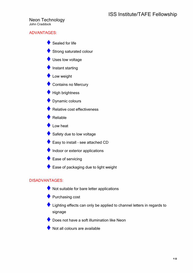
ADVANTAGES:
Sealed for life
Strong saturated colour
Uses low voltage
Instant starting
Low weight
Contains no Mercury
High brightness
Dynamic colours
Relative cost effectiveness
Reliable
Low heat
Safety due to low voltage
Easy to install – see attached CD
Indoor or exterior applications
Ease of servicing
Ease of packaging due to light weight
DISADVANTAGES:
Not suitable for bare letter applications
Purchasing cost
Lighting effects can only be applied to channel letters in regards to
signage
Does not have a soft illumination like Neon
Not all colours are available

ISS Institute/TAFE Fellowship Neon Technology John Craddock
19
APPLICATIONS FOR LED’s:
Paths and stairs
Lifts
Traffic management – in the Netherlands LED’s are placed in roadways
to indicate to motorists which lanes are to be used depending on the
amount of traffic at any given time. This leads to less congestion and a
fuel saving and less pollution.
Torches
Fridges
Edge lit signs – plastic
Matrix signs – Road traffic, all colours available, controllable,
Miniaturised, can operate from mains power, battery, or solar power,
energy saving.
POS – (point of sale) Bright, can match colours or change colours
Emergency situations – Reliable and cost effective

ISS Institute/TAFE Fellowship Neon Technology John Craddock
20
Contacts and information made at SignUK: Malcolm Lant PSS (Professional Sign Systems) 237 Dukesway, TVTE Gateshead Tyne & Wear NE11 OPZ www.pssdigital.com After introducing myself to Malcolm he was more than helpful with his time and information, Malcolm was able to supply me with a CD showing installation methods and advantages of the GE “Tetra” brand of LED’s that PSS were promoting at the exhibition. See attached copy of the CD and please visit www.gelcore.com for further information on the GE brand LED’s.
Malcolm informed me of the popularity of LED’s for channel lettering and that was the main focus of their promotion, LED’s can be installed easily by unskilled workers as the link system can be made to follow any channel shape as long as the LED’s are spaced correctly so as not to produce any dark spots when viewed from the front once the acrylic face has been fitted.

ISS Institute/TAFE Fellowship Neon Technology John Craddock
21
As shown below the components needed to produce LED lighting for channel lettering is minimal and easy to use.
ISS Institute/TAFE Fellowship Neon Technology John Craddock
22
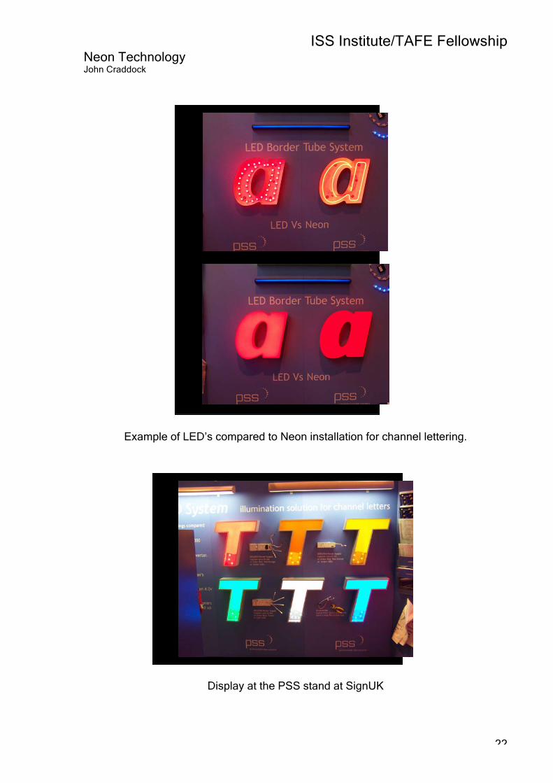
Example of LED’s compared to Neon installation for channel lettering.
Display at the PSS stand at SignUK

ISS Institute/TAFE Fellowship Neon Technology John Craddock
23
Martin Delaney Graphex Limited Lancaster Road Dunston Industrial Estate Gateshead Tyne and Wear NE11 9JG www.graphex.co.uk Graphex is along established company producing a wide range of signage they also were promoting their own brand of LED lighting system “Lightchain”, their system is very similar if not the same as the GE “Tetra” system with the exception being their “Letterbrite” system that incorporates LED’s that are grouped together to provide lengths of LED light as opposed to spots. See illustration below.

ISS Institute/TAFE Fellowship Neon Technology John Craddock
24
“Lightchain” LED system Lightchain is one of the fastest growing methods of illumination according to Graphex and has already converted many companies who have traditionally used Neon as the method of lighting channel lettering. At this stage “Lightchain” is only available in The UK and Ireland from Graphex Ltd. And is promoted as a system that virtually eliminates maintenance costs and reduces running costs substantially, when this factor alone is taken into account the saving can accumulate to a large some depending on the size of the installation. This method of illumination is virtually fit and forget due to high quality of the components used such as the 3M VHB (very high bond) adhesive tape for surface mounting to the substrate.
Image on the left shows a cutaway view of the channel letter above and clearly shows the size and placement of the LED’s required to illuminate this large fabricated letter.

ISS Institute/TAFE Fellowship Neon Technology John Craddock
25
Alan Wilson Saltwell Signs Team Valley Trading Estate Gateshead Tyne & Wear NE11 0TU www.saltwellsigns.co.uk Another contact was Alan Wilson from Saltwater Signs a company that has been established for over 33 years and was one of the first to attain ISO9002, Saltwell Signs were promoting neon as a form of signage over the new LED technology as they felt that it allowed for more creativity in the design and manufacturing process, they see the advantage of neon being in the “Quality of the light” i.e. the soft glow that can only be achieved using neon as a light source. This was clearly shown by the emphasis shown on their stand with neon and edge lit signage being predominate, as shown in the image below.
On the left is a sample of a mirrored 3 dimensional letter with an acrylic back panel backlit with neon lighting.

ISS Institute/TAFE Fellowship Neon Technology John Craddock
26
INDUSTRY VISITS Masonlite Ltd. 36 Second Avenue Chatham Kent ME4 5AX www.masonlite.com Masonlite was chosen as the cornerstone of my Fellowship journey as I knew they were a well established cold cathode lighting components manufacturer supplying products, including cold cathode electrodes, rare gases, and processing tools all over the globe since 1948. To the best of my knowledge the only company providing training in neon fabrication in Europe through the “British School of Neon”, based at the factory in Kent. As much as 75% of Masonlite’s production is exported around the world including the Middle East and Russia. Initial contact was made many months in advance with Becky Devine and Masonlite were kind enough to allow me to visit their factory and school over three days and also organised a visit to a local Sign company “Avenue Signs” who as part of their operation have a small but productive neon workshop. My time at the factory was divided between Chris Skilton who is the Materials Scientist in charge of quality control, and Kerry Wright who teaches at the British School of Neon. I was greeted by Becky on my arrival where she outlined the structure of the company and informed me of some recent changes that have taken place since the original owner Mr. Mason had retired and the company was sold to an American company. Cold Cathode or Neon lighting in not restricted to just signage, it is also used for automotive, avionics, beacons, and architectural lighting.

ISS Institute/TAFE Fellowship Neon Technology John Craddock
27
So how does Neon (Cold Cathode) lighting work? Cold Cathode is a low pressure gas discharge form of lighting, very similar to the Fluorescent lighting so common and popular in our homes and buildings. Another form of gas discharge lighting is seen during a lightning storm. When the high voltage electricity passes through the air, a very bright light is produced.
A Cold cathode tube is very simple. It consists of an evacuated glass tube with electrodes attached to the ends. A small amount of inert gas is added, such as Neon (produces a red light) and Argon (blue light). When the electrodes are connected to a high voltage power source the tube glows. A wide range of colours can be obtained by the use of coloured glass, and/or coating the inside of the tube with a phosphor powder, which emits the required colour when it is excited by the discharge. What is happening inside the tube? When the lamp is turned on, electrons, which have a negative charge, are knocked off neutral gas atoms which become positive ions. The process is called ionization. The electrons move toward the positive electrode, and the positive ions toward the negative electrode. Collisions occur with other atoms which gain some energy. They later release this energy in the form of light. The energy/colour of the light depends upon the gas atom involved in the collision.
The Masonlite factory

ISS Institute/TAFE Fellowship Neon Technology John Craddock
28
The following photographs were taken over two days at the factory in Kent, I was surprised to see how much of the manufacturing process was produced or controlled by people as opposed to being carried out by robotics or mass production devices. It was explained to me that because of the nature of glass depending on the batch or the conditions on any given day the materials need to be monitored closely for breakages or cracks as well as setting the machines to ensure, for example that the correct amount of pressure is applied when crimping glass around electrode wires.
The entrance to the Masonlite facility
An overview of the factory floor

ISS Institute/TAFE Fellowship Neon Technology John Craddock
29
Burnishing the ends of glass tubing that will be made into electrodes.
This is an “emitting” machine; its used to apply Barium based liquid coating to the electrode shell that allows the use of a
lower voltage during operation.
Soldering wire to electrode shells

ISS Institute/TAFE Fellowship Neon Technology John Craddock
30
Electrodes being prepared

ISS Institute/TAFE Fellowship Neon Technology John Craddock
31
The electrode is annealed prior to removal
from the crimping machine.
Annealing reduces the possibility of stress fractures at a later stage of neon production.
Removing electrodes after the shell has been crimped; this is a crucial stage in
production as the wires must bond with the glass to form a seal once the electrode is joined to the ends of tube length.

ISS Institute/TAFE Fellowship Neon Technology John Craddock
32
Masonlite purchase the glass tubing from companies such as “Osram” then go through the process of coating the inside of the glass tube with liquid Phosphor and later put the tubing through a furnace at 400deg. C to remove any impurities, the following images will show that process.
The device on the left measures and pour the phosphor coating to the inside of the
tubes to the right hand side of the picture is the collecting trays the catch any excess coating that can be reused. In the image on the right the tubes are left to dry, all of
this procedure is carried out manually.
These are barrels of the liquid Phosphorus on a turning rack to ensure it is thoroughly mixed prior to use.

ISS Institute/TAFE Fellowship Neon Technology John Craddock
33
The furnace used to bake the phosphor coating and to burn off any impurities from
the glass.
In this image you can clearly see the tubes
glowing red hot from the 400 deg C that they must be heated to effectively remove
any impurities from the coating.
This conveyer is put in place one the glass
starts coming out of the furnace to allow time to cool down prior to being inspected.

ISS Institute/TAFE Fellowship Neon Technology John Craddock
34
Glass tube being inspected for faults such
as cracks or impurities.
Tube being stacked and readied for dispatching.

ISS Institute/TAFE Fellowship Neon Technology John Craddock
35
As part of the quality control procedure batches of electrodes are viewed using
Polarisation to see if there are faults such as the electrode wires not bonding with the
glass during manufacture.

ISS Institute/TAFE Fellowship Neon Technology John Craddock
36
Questions posed to Tony Ralph JC: It would appear from what people have told me that the “British School of
Neon” run by Masonlite was flourishing some time ago but for some reason interest has dropped off, at least for the moment, would you agree with that and do you feel there is any particular reason for it?
TR: Yes the intake at the school has dropped off for various reasons, some decline
in the neon side of the industry, companies not wanting to invest in training, individuals not having sufficient funds to finance their training and our recent cut back in advertising the school due to reorganisation of both the school and the company structure.
JC: How would you recommend attracting people to learn the art of neon
fabrication? TR: The best way ti attract interest is by advertising in trade magazines like “Signs
of the Times” and maybe having a feature column in such magazines. JC: Where do you feel that the neon industry is finding neon fabricators if only a
few people are being trained? TR: Because of the geographical difficulties and in an effort to save money many
companies are trying to train in house. JC: In general terms is the neon industry growing as a market? TR: I would say the biggest areas of growth are in the Middle East, Far East and
Russia and its former satellite countries. Other countries tend to wax and wain in terms of the size or growth. It is true to say that LED’s have had an impact and this will continue and may grow as they improve.
JC: Is there an area that will be affected by new technologies, such as materials fro
example, or any way of making the art of neon easier to fabricate therefore requiring a lesser degree of skill?
TR: Currently other than using jigs or moulds for bending multiple type lettering as
for POP/beer signage the traditional methods still apply.
Continued next page

ISS Institute/TAFE Fellowship Neon Technology John Craddock
37
JC: Is there a reason that glass is used instead of say plastic for example, as there
are so many different types of plastic available for a wide range of applications?
TR: It would seem logical that plastic could be used instead of glass but:- The electrodes would need to have a plastic envelope. The electrodes need to be processed at high temperatures, the plastic would
need to be airtight to keep air out and the rare gas in, Glass is a relatively inexpensive material any plastic which would be suitable would probably be expensive because of the properties it would need and the relatively small market.
Questions posed to Chris Skilton (Materials Scientist) JC: What is the difference between neon lighting and a fluorescent tube? CS: The main difference between neon and fluorescent lamps are the electrodes.
Neon or cold cathode electrodes tend to be large hollow cylinders internally coated with an electron emissive material. Fluorescent or hot cathodic electrodes are usually wire filaments coated in a similar material. The purpose of the electrodes is to release electrons into the lamp to maintain the discharge. During lamp operation, the electrodes, when cathodic (every 1/50 second if running at mains frequency), are bombarded by Argon and Mercury ions. Cold cathode electrodes release electrons from the internal surface of the electrode via secondary emission, usually requiring a voltage drop (cathode fall) of 150 volts. Hot cathode electrons become heated at one point and release thermionic electrons. The cathode fall is usually around 15 volts, but a minimum current is usually required to provide enough heating of the electrode, hot cathode lamps tend to be larger in diameter running at higher currents compared to cold cathode lamps.
JC: Is there any particular reason that tube has to be made from glass? CS: The tube has to be vacuum tight, have a low out gassing rate, transparent,
resistant to ion bombardment, resistant to UV radiation, non conductive, be able to withstand 150c degrees at the electrode, mechanically strong enough to withstand atmospheric pressure, suitable for internal coating with phosphor powders, which currently need baking at over 400c degrees. We are not currently aware of any plastic that meets these criteria.
Continued next page

ISS Institute/TAFE Fellowship Neon Technology John Craddock
38
JC: Do you see a time when Mercury will not be part of neon manufacture, or are
the new electrodes that have enclosed the Mercury sufficient to meet standards around the world?
CS: I don’t see a time when Mercury will be not be part of the process, keeping in
mind that Mercury is only required when Argon is used and for the colours that are produced using it.
Enclosed capsules greatly reduce the amount of Mercury used in the
manufacturing process, no more guessing.
In some parts of Europe, Germany for example, there are strict laws for the disposal of failed tubes. Mercury is not always desirable in neon as in some very cold countries the Mercury can condense to the point that a heater is designed into the construction of the installation.
JC: The basic design seems to have changed little from the time when neon was
first invented. What are the issues that have arisen that have influenced/made changes? Technology? Design? Legislation? Client needs and wants? Marketing?
CS: Because of its basic primitive design it’s unlikely to evolve, there have been
almost no changes to the process used to bend and pump neon from its inception.
Ceramic collars used as a component for electrodes and Mercury enclosed
electrodes have been the most significant changes other than an improvement in the over all quality of glass that is manufactured now.
ISS Institute/TAFE Fellowship Neon Technology John Craddock
39
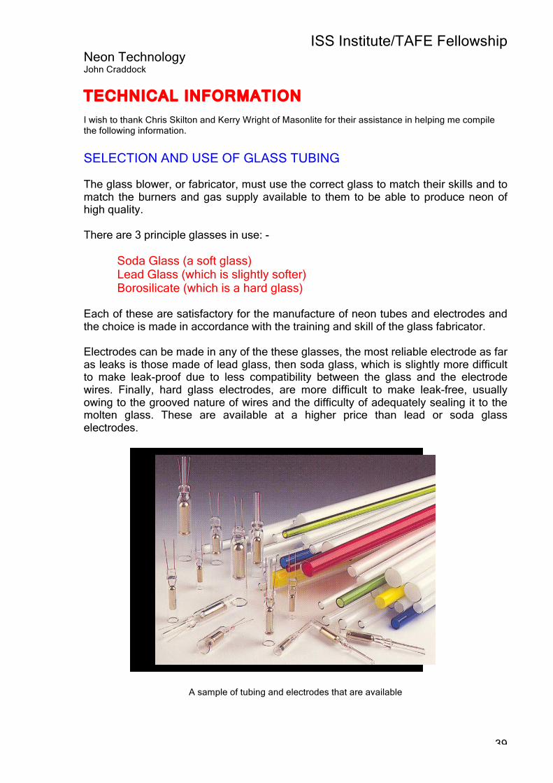
TECHNICAL INFORMATION I wish to thank Chris Skilton and Kerry Wright of Masonlite for their assistance in helping me compile the following information.
SELECTION AND USE OF GLASS TUBING
The glass blower, or fabricator, must use the correct glass to match their skills and to match the burners and gas supply available to them to be able to produce neon of high quality. There are 3 principle glasses in use: - Soda Glass (a soft glass) Lead Glass (which is slightly softer) Borosilicate (which is a hard glass) Each of these are satisfactory for the manufacture of neon tubes and electrodes and the choice is made in accordance with the training and skill of the glass fabricator. Electrodes can be made in any of the these glasses, the most reliable electrode as far as leaks is those made of lead glass, then soda glass, which is slightly more difficult to make leak-proof due to less compatibility between the glass and the electrode wires. Finally, hard glass electrodes, are more difficult to make leak-free, usually owing to the grooved nature of wires and the difficulty of adequately sealing it to the molten glass. These are available at a higher price than lead or soda glass electrodes.
A sample of tubing and electrodes that are available

ISS Institute/TAFE Fellowship Neon Technology John Craddock
40
Burners for Glass Bending Soda Glass Soda glass is of very high quality and comes in 1.5m lengths in a range of diameters from 5 – 25mm, with a wall thickness of 1.1/1.2mm. Soda glass can be worked in the flame, using natural gas mixed with air, in specially designed burners. The use of oxygen is not essential but it does improve flame control as it raises the flame temperature, therefore permitting faster work. Very little oxygen is needed and it is a common practice to introduce it into the air line by means of a small valve and injector, so that the air becomes enriched from its normal oxygen content of 20% to 30-35%.
The image above shows a ribbon burner being used at its full length.
If this method of enrichment is used, it is vital that no oil is present in the pipe lines or valves used for the air supply and that the air blower is a carbon vane type which requires no lubrication. Should these precautions be ignored, the inter-action between oxygen and oil can be highly dangerous. The usual choice of burner for soda glass is the bench burner to give a range of flames from a small sharp blue-tipped one used for joining small diameter tubes to a large yellowish soft flame used for annealing the work. A hard torch is also used for sealing-on electrodes and for use on the pump bench. Finally, a ribbon burner is a necessary piece of equipment and is often available in a length of 60cm or more should be equipped with a slide, enabling the length of the flame to be adjusted according to the work requirements. Soda glass requires careful annealing after a join or bend is made and this should start in a hot flame so that the necessary slow rate of cooling is achieved and any serious stress can be reduced.

ISS Institute/TAFE Fellowship Neon Technology John Craddock
41
Lead Glass The types of burners required for lead glass work are different from those used in soda glass working with the exception of the ribbon burners which are the same for all types of glass. The bench burner is usually a set of cross-fires in which 4 or 5 jets of flame are directed towards a central point from either side from a stand supporting the jets. This type of burner needs a pre-mix of gas and air, which is achieved by the use of a mixing valve containing a suitable injector and controls for varying the size of the flame. The work is carried out at the final point of the flame and the distance between the two sets of opposing flame. Less annealing is required with lead glass than with soda glass, but some should always be applied with a soft flame. When lead glass is heated to melting point in a vacuum, the lead oxide content of the glass will be reduced to metallic lead, which will show up at the point of work as a black band. Hard Glass (Borosilicate Glass) This glass is commonly known as ‘Pyrex’ it has the advantage of being subject to less thermal stress and thus requires very little annealing but it is susceptible to mechanical strain, just as any other type of glass. It is necessary to use oxygen while working with hard glass and for this purpose specially designed burners are available.
Coloured Glass The coloured glasses available are limited to those with a soda glass base, the lead-based coloured glasses having been abandoned. All coloured glass is now hand-made and is of a reasonably good quality from the point of view of dimensional tolerances, straightness and uniformity of colour. It is of course more expensive than clear glass. It is available in a range of diameters from 8mm to 22mm and the diameter tolerances are usually a little greater than those of machine-drawn clear tubing. Coloured glass can be worked with the same type of burners as are used for soda glass, although considerably more care is required when annealing coloured glass. They can be joined successfully directly to soda or lead glass tubes.

ISS Institute/TAFE Fellowship Neon Technology John Craddock
42
FLUORESCENT COATED TUBES The wide range of colours of ‘neon’ tubes used today is obtained by using various fluorescent powders or phosphors in conjunction with a neon filling or an argon and mercury filling. The use of coloured glass, in addition to clear glass with these phosphors, further extends the range of colours of light that can be produced. The coating of the glass tubes with phosphors is generally done in one of two ways: -
a) Manufactured pre-coated tubes b) Glass bead method
a) Manufactured Pre-Coated Tubes The following method is the only type used by Masonlite as it is far more efficient when producing coated tube on a large scale. This type of coated tube is available in a wide variety of diameters, lengths, and colours. The method of manufacture involved is to first clean the clear glass tubes with a special agent, thoroughly wash and dry them and store them in a warm atmosphere in low humidity. The liquid used for coating is a suspension of the phosphor in a solution of nitro-cellulose in butyl-acetate with added binding agents. The suspension is pumped up the vertical tubes and allowed to drain back. A slow current of warm air passes down the tubes to dry them in approximately 30 minutes, after which they are baked to burn away the organic binding agents. This process leaves a clean tube, uniformly coated which can be pumped much more quickly and easily since impurities have to a large extent, have already been baked out before the glass fabricator starts work with it. After baking and cooling, the tube ends are taped up to prevent any dust entering at the open ends and also to indicate the colour of light given in use. White, blue, green, rose and yellow tapes are used in addition to the catalogue code numbers and manufacture’s reference which are stamped on the tube at both ends and burnt into the glass. Tubes are then tied up in bundles of 50, labelled and packed in a sealed polythene envelope to exclude dirt and dust.

ISS Institute/TAFE Fellowship Neon Technology John Craddock
43
(b) The Glass Bead Method The following method is not commonly used Masonlite sell bottles of phosphor powder suitable for the following coating method, it has the advantage of potentially producing a more uniform coating within the tube with no thinning at the bends as it is introduced after the tube is bent. However, it does require a degree of skill and there can be tube contamination problems if not carried out properly. Solid glass beads should be used of an average diameter of 1½ - 2mm. Before use, these must be thoroughly cleaned. If new, the beads should be cleaned in a dilute solution of 3% of hydrofluoric acid for a few minutes, the acid should be removed by running tap water and finally rinsed with the distilled water before the beads are dried thoroughly. It is important to keep the clean beads in a clean and dust-free container. Transfer ¼kg of the clean beads to a ½ kg clean polythene bottle, roughly half-filling it, and add 1 ½ ml of our 2% fluorescent binder and thoroughly shake the beads to achieve even distribution.
Cleaning the Glass Tubes It is very important that the tubes are perfectly clean before the binder is introduced, to prevent blemishes which will worsen during the life of the tube. The glass should be cleaned by thoroughly washing with a dilute acid, such as nitric, or hydrofluoric acid. The acid is removed first by tap water and a final rinse with distilled or demineralised water is recommended. The tubes are then dried and inspected. If spots or patches can be seen, cleaning was unsatisfactory and must be repeated. Applying the Binder to the Tube The glass tube to be dust-coated is closed at one end and the binder-coated beads are poured through a funnel into the other end, until one third of the tube is filled. Then the open tube end is also closed, and the glass beads are gently shaken about in the tube to transfer the binder from the beads to the glass wall. It is important that the beads come into contact with every part of the tube and an experienced operator can discern an even bluish tinge when this part of the process has been completed. Then the beads are poured out of the tube into a suitable container, in which they are soaked in acetone for some hours for cleaning. They are removed from the acetone bath and washed in tap water, finally with distilled water, dried, and are then ready once more for the addition of binder and the beginning of the coating cycle.

ISS Institute/TAFE Fellowship Neon Technology John Craddock
44
Applying the Powder Tubes coated with a film of binder should be powdered with the fluorescent compounds as soon as practical, an excess of fluorescent powder is introduced into the tube and this is made to adhere to the glass wall by a combined shaking and tapping operation, the excess powder being allowed to escape. Baking is not normally required, unless the tube is a particularly large volume one, in which case a pump might be inadequate to cope with the vapour given off. In this case baking can be carried out in an oven at about 250°C for half an hour, or alternatively, the tube can be heated progressively from one end to the other by means of a large hand torch flame, whilst both ends are open to the atmosphere.
ISS Institute/TAFE Fellowship Neon Technology John Craddock
45
SELECTION OF TUBING
TUBING – Diameter and running current in milliamperes (m/A) The common diameters of tubing currently in use are 12mm, 15mm, 18mm and 20mm. It is possible to obtain tubing in diameters from 3mm to 40mm in, In the United Kingdom the most popular diameter is 15mm, followed by 12mm and then 18mm, although for cold cathode lighting purposes 20mm diameter tubing is standard almost everywhere. There appears no clear cut explanation of these choices but two important factors appear to be that in the cold weather countries, a short wide tube is less susceptible to cold weather fading and, in addition, the maximum permitted transformer voltage. In countries where cold weather can be experienced the smaller tube diameters are more common. The selection of the diameter of tube to be used in the construction of a neon sign should be decided depending on the size and complexity. A small letter with complex bends should be produced using a small diameter tube, and very large designs could employ banks of straight or gently curved tubes of 20mm diameter. The next factor to be decided is the operating current of the tube. This can be 25 to 35mA, 50 to 60mA or 90 to 120mA and should be decided according to the surrounding circumstances in which the tube it to be operated. For long life and trouble free operation a lower current is preferable, such as 25 – 35mA, but where tubes are concealed within plastic-faced letters or boxes, it may be necessary to counter-act the absorption of light by these materials by running the tubes at 50 – 60mA. In relatively few cases it is necessary to run sign tubing at 90 – 120mA.

ISS Institute/TAFE Fellowship Neon Technology John Craddock
46
ELECTRODES
Once the tube current has been selected, then the electrode an can be chosen to suit, it’s not necessary that the diameter of the glass of the electrode should be equal a skilled glass-blower can produce a good join between tubes of various diameters. A well trained and experienced Neon fabricator should be able to join a lead glass electrode to a soda glass tube and vice versa, but with hard glass tubing you must use a hard glass electrode.
A typical electrode
Most countries of the world use 20% lead glass for sign tubing and lead glass electrodes to match. This combination originated in America in the 1930’s, and gradually spread all round the world with an exception of Europe. It is the most logical choice, the tubing is easy to bend for sign work especially in the thicker wall (1.4mm) normally used; it requires less annealing than soda glass and can be fluorescent coated or bent with less damage to the phosphors since it can be bent at 80-100°C lower temperature than soda glass. Lead glass is also more suitable for electrode making than soda, since the sealing wire commonly available- Dumet wire, an alloy of Nickel and Iron mechanically coated with copper, and then coated with borax as a flux – was originally designed to match the thermal expansion properties of lead glass rather than soda glass. It’s ideal for sealing into a lead glass tube to form lead glass external pinch electrodes, the pinch can be made virtually strain free and can even have a 4mm diameter tube sealed into the pinch between the two. Typically electrodes are catalogued with for size and rating, for eg. 16/50c, 16 represents the diameter of the tube and 50 represents the mA rating. Electrodes with self contained Mercury

ISS Institute/TAFE Fellowship Neon Technology John Craddock
47
Until fairly recently when a Neon fabricator was producing a section of tube that was to be filled with Argon gas (only Argon requires the addition of Mercury) they needed to introduce a small amount of Mercury inside the tube, this was done using what is called a Mercury trap, which was really just a bubble made in the pipet tube leading from the pumping station to the tube section. When the tube had been pumped and bombarded the Mercury would be gently shaken into the tube, this meant that the Neon fabricator had to handle small amounts of Mercury, perhaps over many years. The problem is that Mercury evaporates and the vapour is toxic, this is where the term “Mad as a Hatter” came from as in early times Hatters used Mercury around the brim of hats they made, allegedly leading to mental illness! Today, technology allows Neon fabricators to use electrodes that have a small amount of Mercury enclosed in the electrode that can be released by placing a high frequency coil around the electrode once the tube has been separated from the pumping station, prior to aging the tube.
Note the Mercury enclosed capsule inside the electrode
The advantages of electrodes with enclosed Mercury are:
No loose Mercury in the workplace
Accurate quantity of Mercury
Increased productivity
No Mercury traps
No contamination risks almost eliminated
No Mercury contamination to the pump system

ISS Institute/TAFE Fellowship Neon Technology John Craddock
48
Activated and non activated electrodes Activated electrodes have the internal electron emissive coating which lowers the cathode fall voltage and aids bombarding by slowing down electrode heating. You can see an image of the “emitting” machine on page 30; it coats the inside of the electrode shell with Barium Fluoride. Unactivated electrodes run at a lower current for a given size due to the higher cathode fall. However, a small number of Neon fabricators use them because they believe the risk of tube contamination is reduced from having no emitter coating,

ISS Institute/TAFE Fellowship Neon Technology John Craddock
49
TECHNIQUES OF PUMPING The purpose of pumping is to heat the tube and electrodes to a sufficiently high temperature for a long enough time under vacuum to remove all impurities and to activate the electrode coating. Following this, the tube is allowed to cool slightly while obtaining the best possible vacuum, and is then filled with the required gas to the correct pressure. The detail of the procedure varies according to whether a high voltage Bombarder or a high-frequency generator (oven pump) is used. It also varies according to the diameter and length of the tube, the size of the electrodes, whether they are activated or not and the type of the activation. PUMPING WITH THE HIGH-FREQUENCY GENERATOR (H.F.OVEN PUMPING) The equipment required for this type of pumping is a large oven which can accommodate multiple tubes, either straight or curved, a pumping unit with a rotary oil pump backing a two or three stage diffusion pump and vacuum stopcocks, gauges and gas-filling facilities and finally the high frequency generator itself, these are sometimes referred to as an “eddy current heater”. This should have a power capacity of 0.5 to 1.0kva, should be on castors to permit moving it around the oven, and it may have an air-cooled or water-cooled work coil with 2 to 2.5 meters of cable and rely control button on the handle.
View of High Frequency oven pump with the oven door open, it has the capacity to
pump multiple sections.

ISS Institute/TAFE Fellowship Neon Technology John Craddock
50
Tubes fitted with inactivated electrodes may be pumped in the oven without the use of the H.F. generator, if so desired. In this case the heat of the oven at a temperature just below that of the softening point of the glass is sufficient to out-gas the electrode shells if they are of the usual standard of purity and cleanliness.
Diffusion pumps use a high speed jet of fluid to direct residual gas molecules in the pump throat down into the bottom of the pump and out the exhaust. The high speed jet is generated by boiling the fluid (typically silicone oil) and directing the vapor through a multistage jet assembly. Often several jets are used in series to enhance the pumping action.
Unlike mechanical pumps, diffusion pumps have no moving parts and as a result are quite durable and reliable. They can function over pressures ranging from about 10-10 torr to about 10-2 torr. Diffusion pumps cannot discharge directly into the atmosphere, so a mechanical forepump is typically used to maintain an outlet pressure around 0.1 torr.
With all tubes sealed carefully open the main tap to vacuum and check for leaks, when all is in order as indicated by the vacuum gauge, switch on the heat and bring the work load up to 420°C in about 45 minutes. When a good vacuum is showing 5x10¯ ³ torr or better, switch off the heat, lift the oven lid carefully and apply the H.F. heating coil to the electrodes one after the other. The pump main stopcock is open all the time. This will bring the shells to a uniform bright cherry red heat. Take care not to heat the lead-in wires. An ON-OFF push button on the coil handle is necessary here to avoid the risk of under or over heating the shell. It is a good idea to have the vacuum gauge visible to the pumper as he goes round with the coil so he can see the gases coming off the electrodes and knows when the emission is finished. When all are done, and a good vacuum is once again obtained, it is a safeguard to go round a second time with the coil bringing the shell up to red heat for a second or two and watching the gauge to ensure no more gas remains trapped. Then, after restoring a good vacuum close the oven lid apply the heat and bake for half hour not exceeding 420°C, pumping continuously. The oven may then be switched off and cooled and by the time the temperature is down to 50-60°C, the vacuum should be 1 x 10¯³ or 5x10 ^-4 torr. Fill with the correct pressure of argon or blue gas and seal off. This method of pumping produces the best quality cold cathode lamps for lighting purposes giving the highest light output, and the longest life since there is no electron stream bombarding the phosphors. It is not suitable for Neon filled tubes since a good neon red colour is rarely obtained. For these the bombardment must be used.

ISS Institute/TAFE Fellowship Neon Technology John Craddock
51
PUMPING WITH A HIGH VOLTAGE BOMBARDER
Activated Shell Electrodes (Barium Fluoride) This kind of activation is suitable for the “closed stopcock” method of pumping because very little gas is produced when the electrode shell is red hot. Sealing-On Seal the tube to the pump, open to vacuum, and switch on Bombarder, set to minimum.
Preliminary Pumping When pressure is sufficiently reduced, the tube will light up and should run at a minimum, approximately 100-150mA, until the pressure is no longer enough to support the discharge. The main tap should be closed at this precise moment or the tube may shatter if the discharge is allowed to continue at too low a pressure. The pressure is now allowed to build up whilst the current is raised to 400-500mA.
Heating Glass Work This build-up of gases should not be allowed to continue for too long, or it will extinguish the discharge, the main tap should be open fractionally or momentarily, to pump out impurities as they are freed by the rising temperature of the tube. After a few moments the tube will be seen to be heating up, the temperature reached should be about 250°C.
The tube temperature is best indicated by a portable pyrometer as shown n the image below, many Neon fabricators that I spoke to preferred the method of laying a small strip of newspaper over the tube and gauging the temperature as being correct when the paper starts to turn brown, some tried and true methods are still more popular than some modern technology.
A portable pyrometer used to keep a check on tube temperature during pumping.

ISS Institute/TAFE Fellowship Neon Technology John Craddock
52
Heating Electrodes At this point the electrodes will be approaching a dull red heat and should start degassing. Momentarily open the stopcock to pump away this gas as fast as it is formed, failure to do this will result in dark bands developing early during tube life. The electric current may now be increased until the electrodes are bright red, at which they should be maintained for a few seconds, or until no further gas is formed. Now open the main vacuum tap fully, switch off the current and allow it to pump out.
This procedure should be varied according to the size of the electrodes being pumped. Larger electrodes will require a higher current for a longer time than smaller ones. If 20kV is necessary to start with, it may be desirable to switch off momentarily after the initial stage when the glass has become hot, and turn the selector from 20kV to 10kV then switch on and proceed. Generally, longer tubes are easier to pump than short ones, since there is a tendency to overheat the electrode on very short tubes, often resulting in a black deposit of sputtered metal at each bend in the tubes, and around the tip of the electrode shell.
Pumping Activated Shell Electrodes (Mixed Carbonates) This activation requires a more “open stopcock” method owing to the higher temperature required to decompose the carbonates and the considerable volume of carbon dioxide generated in the process. Although taking a few seconds longer, it has the advantage of allowing the glass tube to become hotter whilst the main stopcock is open or partly open, a condition desirable with some kinds of phosphates to avoid discolouring or damaging them during the pumping process. Sealing-On Seal the tube to the pump, open to vacuum, and switch on Bombarder, set to minimum.
Preliminary Pumping When pressure is sufficiently reduced, the tube will light up and should run at a minimum, approximately 100-150mA, until the pressure is no longer enough to support the discharge. The main tap should be closed at this precise moment as the tube may be shattered if the discharge is allowed to continue at too low a pressure. The pressure is now allowed to build up whilst the current is raised to 400-500mA.
Heating Glass Work The additional build up of gas pressure from this activation will extinguish the tube, as can be seen by rapidly falling milliamps. Open the main stopcock until m/A rise to about 500-700, depending on the tube diameter, then close it. As more gas is produced the m/A will fall and should be kept up by opening and closing the stopcock. When it seems steady and no more gas is produced, the tube temperature should be about 250°C.

ISS Institute/TAFE Fellowship Neon Technology John Craddock
53
Heating Electrodes At this point the electrodes will be approaching a dull-red heat and should start de-gassing freely; the gas is mostly carbon dioxide and should be pumped away as fast as it is formed by opening the main stopcock. Failure to do this will result in dark bands or shadows developing in the tube section which will affect the light output and the life of the section. At this point you may see that the electrode shells are red hot and the current may now be increased by a small amount, 50-100mA, to give the final clean. They should be maintained at bright red for a few moments or until no further gas is formed. If gas is liberated, then the milliamps will be automatically reduced and should be restored by momentarily opening the main tap. When the section us stabilised, that is, tube temperature around 250°C, electrode shells red-hot and milliamps steady with no further evolution of gases, then the bombardment is finished. Open the main stopcock fully, switch off the current and allow the tube to pump out and cool.
Testing After a few moments, when the tube is cooled down to approximately 100°C and a high vacuum obtained at least 5x10¯ ³ torr, 3-4 torr of cleaning gas or Helium can be admitted and the Bombarder switched on at three times the rated current loading of the electrodes (e.g. for 16/50C this will be 150mA). The tube should run at this current for at least two minutes without any material change in the golden colour of the discharge. If a rapid change in colour does occur, it means either there is a leak or that impurities are still being released from the section and it is then necessary to repeat the previous bombardment. The tube may then be pumped out to high vacuum, not forgetting to hand-torch the mercury pocket and the stem-tube between it and the section carefully with a soft flame to avoid any sucking-in. This serves to remove impurities from the glass and also the mercury.
Filling The tube should now have cooled to 50°C or less. After checking the final vacuum is 1x10¯ ³ torr or better, there should be no continuous glow using high frequency tester, fill with required gas after reference to the following table and seal off. The required gas depends on the requirements of the tubes; fluorescent tubes may be filled with pure Argon or any mixture of Argon and neon up to pure Neon. This, with mercury vapour generates the ultra-violet radiation necessary to activate the various phosphors used to produce the wide range of whites and colours in popular use today. Mercury vapours, however, like all vapours are affected by changes of temperature, and will condense to form liquid mercury as the temperature is lowered. When a mercury sign is first switched on it may not therefore reach its full brilliance until the heat of the discharge has vaporised sufficient mercury.

ISS Institute/TAFE Fellowship Neon Technology John Craddock
54
The heat of the discharge may be varied by varying the composition of the filling gas. Pure argon has the lowest effective resistance and consequently generates the least amount of heat. It is used in hot cathode lamps or in cold cathode lamps or signs used indoors above 10°C. For signs used outdoors from 0°C to 10°C, a popular mixture is 75% Argon + 25% Neon, and for outdoor temperatures of 0°C to –10°C the best mixture is 75% Neon + 25% Argon. Recommended Filling Pressure Older gauges were calibrated in millimetres of mercury or in torrs.
The later ones are in millibars – 1,000 millibars = 1 atmosphere = approx. 760 mms. 1 Torr = 1mm mercury pressure = 1.33 millibar.
Neon Gas Tube Diameter Argon Gas Torr Millibar Torr Millibar
20 17 15 12 9 6 6
27 23 20 16 12 8 8
8/9mm 9/10mm
11/12mm 14/15mm 17/18mm 20/21mm 24/25mm
12 12 10 8 8 6 5
16 16 13 11 11 8 7
Where the length of a tube is 30cm or less, we recommend increasing the figure for neon-filling by one third. Tubes should be filled warm 30°C – 50°C. Each gas flask should be fitted with 2 high-vacuum stopcocks, having bore of 3mm and spaced about 100mm apart. Before each filling, this space must be thoroughly evacuated, then after closing the main vacuum stopcock, the upper gas flask stopcock is closed and gas admitted to the evacuated space by opening and closing the lower stopcock nearest the flask. This gas is then transferred to the manifold and pumped tube by opening and closing the upper stopcock. The operator will observe the reading on the manometer or the capsule dial gauge and repeat the operation until the required gas filling pressure is obtained. When the gas flask is new and under almost atmospheric pressure one transfer may be enough, as the gas is used its pressure drops and more and more transfers are needed until it is possible to leave open the lower stopcock and carefully to open the upper stopcock valve while watching the gauge, until the correct filling pressure is obtained.

ISS Institute/TAFE Fellowship Neon Technology John Craddock
55
Frequent use of the H.F. testing coil is recommend, first of all, to check that the gas flask is not contaminated, then to check that a good vacuum is obtained in the manifold and space between stopcocks and finally, to check that the gas colour in the tubes after filling is correct. When using a high frequency testing coil, the contact between its electrode point and the glass should be very brief for two reasons. One is that a long contact time can puncture the glass unless the coil output is of a very high frequency and the second reason is that, at the point of contact, the glass will heat up and will release further impurities into the system.

ISS Institute/TAFE Fellowship Neon Technology John Craddock
56
Aging Aging consists of operating tubes on a high-tension circuit, using a current which is a little higher than the normal rating for the electrodes – 20-25% over-running is usually adequate. Aging of tubes filled with Neon should be almost immediate, although in the case of short tubes, less than about 30-40cm, it is often found that the discharge will at first have a slightly bluish tinge, which will disappear after 10 minutes of aging, leaving the correct Neon colour. Sometimes it will be found that tubes exhibit snaking and wriggling. This is due to small traces of impurities remaining in the electrodes or possibly in the mercury and can usually be cured by switching the circuit on and off a few times and allowing the tube to run at about 25% over standard rating. If snaking persists, it is usually necessary to re-pump the tubes. It is a good idea to touch the tubes by hand to detect whether they are running at normal temperatures or too hot, since a tube which has a slow leak may be pumped satisfactorily and survive a short aging period before the leak begins to be apparent. In addition to an increase in tube temperature, a very small leak will also influence the intensity of light produced and the colour of the light. A larger leak produces the familiar purple discharge attributed to air and will soon cause the tube to flicker and extinguish. Re-pumping of Old Tubes It is possible to re-pump old tubes but it is generally not a practical exercise depending on the condition of the tube for example there is no way of detecting areas of stress in the tube sections and may not be durable after re-pumping. Also the condition of all the electrical components needs to be taken into consideration. In most cases it is far more reliable and practical to make new sections and replace the electrical components.

ISS Institute/TAFE Fellowship Neon Technology John Craddock
57
PUMP MAINTENANCE If a pump fails completely, then it must have some repair of maintenance done on an urgent or remedial basis, but long before that stage is reached, the poor vacuum given by such pumps can seriously affect the life and quality of the tubes produced on it. The purpose of pumping can be briefly summarised by saying that the tube is heated under vacuum to remove impurities, and having done this, the tube is then filled with the correct gas, wether neon or argon, or a mixture of both. For the purpose of neon sign manufacture, a pump has two main characteristics. Its rate of pumping (so many litres per second) and its ultimate vacuum – usually measured in Torr or Millibars. If either of these characteristics is not up to its best, then poor results will be obtained. For instance, if the pumping speed is too slow, then impurities which should be removed quickly are left in the tube long enough to react with important constituents of the fluorescent powder perhaps, or with the activation materials in the electrodes, and could do damage to either or both of these. Poor ultimate vacuum which is usually associated also with slow pumping can affect the life of the tube, in that impurities are still left behind even behind even under the best vacuum the pump can produce. Thus the filling gas is introduced into a tube, which has already got a small quantity of various unknown gases in it, and they tend to affect colour of the tube and also give rise to black discharges or bands of discolouration along the electrode and the tube. This effect of poor ultimate vacuum can be mitigated to some extent by flashing the tube out with cleaning gas (a mixture of neon and helium), thereby diluting the impurities substantially before the final filling gas is introduced, but it is only a temporary stop-gap measure, and is no substitute for an overhaul of the pump and the pump system. On new equipment such a vacuum can be obtained rapidly, for example, on the new units Masonlite produce, the standard test is to seal on a tube 25mm in diameter and 3m long and measure the time between opening the vacuum tap and reaching the 10¯ ³ torr. The time on new equipment should be approximately 30 seconds. As its life continues, the pump probably takes longer to reach this ultimate vacuum, but, provided it does reach it, another few moments or even few minutes need not make any difference. It is when the pump can no longer produce such a vacuum and takes a longer time, for example, 3 or 4 minutes before reaching even 5x10¯ ³ torr that you may encounter trouble when pumping. The correct treatment is to dismantle the two pumps, both rotary oil pump and diffusion pump, and to clean them both carefully in accordance with the manufacture’s instructions.

ISS Institute/TAFE Fellowship Neon Technology John Craddock
58
Any further overhauling, or repair work that may need to be done, should be referred to the manufacturer or to a company such as ourselves who can offer this service. The cost is usually small in relation to the value of the pumps and to the value to the work they produce. Every Neon fabricator should be able to do some maintenance on their equipment, and this could be on the basis of an oil change in the rotary pump once a year and a check on the diffusion pump that the diffusion fluid has not been lost through evaporation into the system. Any accidents on the pumps such as a section breaking suddenly whilst being pumped, usually forces powder and other impurities (perhaps broken glass) into the pumps which may give rise to contamination or damage and after such an incident every pumper should inspect his pump for signs of such damage. Cleaning a diffusion pump, whether it is oil diffusion or mercury vapour diffusion, calls for a very high degree of cleanliness on the part of the operator. Really meticulous cleanliness on the part of the operator is necessary, to the extent of avoiding finger printing any of the components during the final assembly, and of course in using grease solvents of the highest purity in themselves. With the best possible care, it is still necessary to operate a diffusion pump for a period of around 8 hours continuously after the cleaning so that traces of vapour, which have become absorbed in the metal surfaces, can be fully removed. The various pump manufacturers all provide detailed instructions for such a cleaning operation. In addition to the pumps, there is of course the system, the network of glass tubes and stopcocks connecting it altogether. Too often this is allowed to grow in length and diminish in diameter; both factors have a bad influence on pumping speeds. Ideally, a pumping system should be very short and very wide. For example, 20mm diameter at the pump itself, for a length of no more than 300mm to 500mm to the section being pumped. The main stopcock should, of course, be as wide a bore as is practicable in order to keep the flow path unobstructed. Side entries, such as for the gas bottle line, or any measuring equipment, can be of small bore tubing which does not waste gas in a way a wide bore tube would do. Since ever stopcock is a potential leak, pumping units have the minimum number necessary for proper operation. There is only one large stopcock with a bore of at least 10mm; 15mm bore is preferable. The two or three pairs of gas filling stopcocks, the blow-rubber stopcock and the manometer (pressure gauge) stopcock can all be of the same type and bore – 3mm. These must be re-greased frequently depending on usage and temperature and must be constantly checked for leaks. Before greasing a stopcock, it is necessary to clean out the old grease with a lint-free cloth and a grease-solvent, to dry and slightly warm the stopcock key, and with a finger smear a small amount of grease all over the surface of the key only, taking care

ISS Institute/TAFE Fellowship Neon Technology John Craddock
59
not to allow any into the bore passage of the key. The key is then re-inserted into the stopcock and turned a few times until the thin layer of air is excluded and the stopcock appears transparent. Excess grease should be avoided, since it blocks up the bore and is exuded from the ends of the key. Only high-grade vacuum stopcocks should be employed for this work. Metal valves require little maintenance, provided they are not roughly used. The seal is made by means of a rubber diaphragm which can be burred or cut if over-much forced is used. These diaphragms are replaceable but should have a life in excess of one year with average care. From time to time, the whole glass manifold should be cut off from the pump and either renewed with clean glass, or carefully cleaned out to remove broken glass, fluorescent powder, mercury and the various other impurities that usually accumulate. After re-assembling, the manifold should be closed and allowed to pump for some time being warmed slightly with a hand torch to ensure that there are no vapours remaining to contaminate the rare gases. Oil manometers need a change of oil occasionally; using only the special grade oil made specifically for the purpose and here again the oil may contain air, which will bubble up the first time it is under vacuum Capsule dial gauges, which have been fitted to pump systems for many years, need very little maintenance but, if found to be reading incorrectly or sticking; they should be returned to the factory for maintenance. The latest models are calibrated in millibars and this should be kept in mind when filling, since 1 torr = 1mm mercury pressure = 1.33 millibars. An electric vacuum gauge should be used from time to time to check the final vacuum the pump can achieve and, if this is not up to standard, then some maintenance work is required. It is not necessary to constantly check vacuum, since a good Neon fabricator can tell by the use of his high-frequency testing coil whether the vacuum is of the required standard or not, and his check can be substantiated with the occasional use of an electric vacuum gauge.

ISS Institute/TAFE Fellowship Neon Technology John Craddock
60
INSTALLATION OF NEON TUBES Each country has its own regulations concerning the installation of Neon or High Voltage Lighting, and it must be assumed that every installation engineer is properly qualified and is familiar with the local requirements. The way in which an installation is made does have a large bearing on the efficiency and life of the sign. To illustrate good working practices and to help in avoiding the pitfalls, it is useful to divide installations into three Groups: -
1. Interior signs and cold cathode lighting.
2. Smaller exterior signs completely assembled in the workshop.
3. Larger signs assembled on site. 1. Interior Signs These take the form of a set of neon tubes mounted on a glass or acrylic or metal panel, which may be sign-written or silk-screened to emphasise the wording, design or colour. a) Blacking- out The tubes may have to be blacked-out, or blocked-out, between letters etc., and for this a specially prepared paint is used, having a high electrical resistance, i.e. a poor conductor, otherwise high voltage discharges can occur which produce ozone gas which will attack cables and parts and have a damaging effect on the sign. For the same reason, blacking out electrodes should be carried out only up to the open edge of the electrode shell, and not right up to the pitch or lead wire. If a colour is required on top of the black-out paint, it too should have insulating properties.

ISS Institute/TAFE Fellowship Neon Technology John Craddock
61
b) Tube Supports These should be of glass or porcelain, ceramic or plastic. Supports for tubing are available in many varieties to suit many various applications.
It is recommended that the transformer used to supply tubes supported on an acrylic panel be fitted with an earth leakage protection switch and spark gap. This device will automatically disconnect the transformer supply, in the event of an earth leakage current flowing or if a tube breaks. Where a panel is not enclosed, as in a box sign, the rear connections should be out of reach of the general public and the electrodes and cables covered by suitable insulator. Window framing border tubes, likewise, must have their series connections carefully protected by an insulator or other effective means, to prevent any danger to the public. Risks arising from moisture in shop windows should be given special consideration. Frequently, window signs are fed from a transformer mounted on the ceiling above the panel. Such panels must always be supported by at least two well-fixed chains or chords such that, if one should break, the other can support the weight temporarily, high tension cables must be as direct and short as possible and proper attention given to their end terminations.

ISS Institute/TAFE Fellowship Neon Technology John Craddock
62
c) Portable Signs Portable signs fed from a low-power wall socket, must be earthed if the casing is of metal. If they are wholly enclosed in insulating material and have no exposed metal parts, then neither the transformer secondary circuit nor the core need to be earthed. Where electronic invertors or high-frequency circuits are used to light the tubes, the use of all insulating material is recommended for the casing, and earthing is not necessary. Manufacturer’s recommendations, however, should always be followed. Often these invertors supply power at less than 1000 Volts (1500v for DC) between conductors or 600 Volts (900v for DC) between conductors and earth, if so, the Regulations pertaining to ‘Low Voltage’ apply. Whether electronic invertors or traditional transformers are used in portable signs, care must be taken to prevent the possibility of fingers touching any live metal should the tubing be removed or accidentally broken. One method is to support the tube on its electrodes in insulating tubes being part of the base and of sufficient length and diameter to avoid this risk. Another is to enclose the whole sign in a transparent plastic case.
Smaller Exterior Signs Whether these be illuminated by neon tubes or hot cathode lamps, it is customary to finish the sign completely in the workshop, leaving only the fixing of sign brackets and low tension mains wiring to be done on the site. This gives an excellent opportunity for the inspection of quality control people to ensure that everything is in order, and that early maintenance calls will be avoided. Plastic panel box signs must be checked for the appearance and spacing of letters, for the spacing of hot cathode lamps to avoid shadows or uneven illumination, for the correct wiring, good contact between lamp pins and socket, and especially in the case of multiple lamp circuits check for adequate power factor correction. Metal box signs using neon tubes should have electrode holes fitted with porcelain or glass bushes, and be accurately made so that the tube can be central in its hole, inter tube connections are preferably made in nickel wire in 6mm series glass tubing. The transformer can be mounted in the roof of the box or on the vertical side wall nearest the brackets so that their weight is not supported only by thin sheet metal or plastic but has a re-enforcing plate held by the brackets. Even in small box signs, transformers need to be ventilated and at the same time kept dry. A combination of louvres and drain holes can be made to achieve this safety. The

ISS Institute/TAFE Fellowship Neon Technology John Craddock
63
metal box and transformers must be properly earthed electrically back to its distribution boar. Larger Signs assembled on site First of all let’s consider large box signs, and long runs of fascia signs lit by Neon tubes. It will be assumed that factors such as number of tubes to give the required light output will uniformly illuminate the plastic fascia panel, have already been decided by reference tables, or from experience. Of course competition from surrounding signs must be a factor and this must be considered at an early stage so that the right number of tubes is selected and that these are spaced properly from each other and from the fascia panel. This together with summer heat, certainly in Australia, could easily raise the temperatures inside a box from an outside ambient of 20°C to temperatures in excess of 80°C if proper ventilation is not provided. Such excessive temperatures can be very damaging and the lamps will operate at a lower efficiency (optimum is obtained about 25/30°C) The colour of the light will change with temperature The electrodes may overheat and shorten tube life The ballasts may overheat and or leak compound or burn out, the high power factor capacitors may also fail under high temperatures causing failure of the ballast also. Ventilation is thus of prime concern and should be built in during design in relation to the volume of the box, the electrical load and the site conditions. Where fascia box signs are constructed of aluminium extrusions the acrylic panels may be either suspended from a top rail in the box, or if not too deep may be supported in a channel formed by the bottom rail. Allowance must at all times be made for the expansion of the acrylic panel to avoid buckling in the sun. Where very large panels are used, additional interior supports will be needed. Such panels offer very high wind resistance and can crack or damage lamps, if they deflect too far into the box. Conversely swirling gusts of wind can create a vacuum strong enough to suck panels from the box and fling them to the ground. Adequate depth of edge covering together with a properly designed top suspension of the panel can overcome this risk. Easy access to the lighting tubes for cleaning and maintenance must be designed into every fascia box, and the site must be surveyed with this in mind. Particular importance should be given to the following points:

ISS Institute/TAFE Fellowship Neon Technology John Craddock
64
1. Proper use of high tension cables.
2. Restrict length of high tension cables to about 5m maximum from each pole of transformer.
3. Adequate spacing around electrodes to nearest earthed metal.
4. Continuous earthing of transformer, cables and metal letters.
5. Installation of transformers to avoid water entering.
6. Cables ends properly made in correct size high tension ends.
7. Correct calibration of transformer with the load of tubes, and this should include measurement and recording of the mains supply voltage on the site and the tube current in milliamps.
CONCLUSION The successful construction and installation of neon is based on good design principles and understanding the science required to produce neon. Workers need to be both designers and technicians who must work in close harmony, and have practical workshop experience. The technician in particular, whether they are concerned with the glass shop, the manufacturing and assembly, installation, or in some cases all three together, should have had a good understanding of electricity and general science.

ISS Institute/TAFE Fellowship Neon Technology John Craddock
65
How is a working piece of Neon created? The following set of images aim to give a basic overview of how a working piece of Neon is fabricated, the images are of Kerry Wright, Teacher at the British School of Neon, Kerry has spent the majority of her life working as a Neon fabricator and moved from Yorkshire to take up the position at Masonlite.
The first step is to attach electrodes at each end of the tube.
To do this the tube must be plugged at one end with an air line attached, so the fabricator can apply air pressure to the tube by blowing air
down the line from her mouth.
Here the other end of the tube is being sealed off
In this image a hole has been blown into the top part of
the tube and an electrode is being attached over the hole, at this stage the electrode is placed at right angles
to the tube.
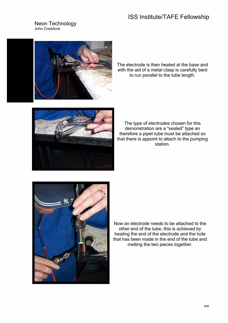
ISS Institute/TAFE Fellowship Neon Technology John Craddock
66
The electrode is then heated at the base and with the aid of a metal clasp is carefully bent
to run parallel to the tube length.
The type of electrodes chosen for this demonstration are a “sealed” type an
therefore a pipet tube must be attached so that there is appoint to attach to the pumping
station.
Now an electrode needs to be attached to the other end of the tube, this is achieved by
heating the end of the electrode and the hole that has been made in the end of the tube and
melting the two pieces together.

ISS Institute/TAFE Fellowship Neon Technology John Craddock
67
The pipet is attached to the glass tubes of the manifold on the pumping station.
At all times care must be taken so that there are
no stress fractures, this is achieved in part by annealing the glass as is seen here where a
gentle flame is used over the joins.
Here a temperature sensor (Pyrometer) is set up to allow the operator to keep check as the pumping takes place as the glass cannot be allowed to get too hot as the electrodes may
burn and in extreme cases the tube may implode.
A temperature of no more than 250c is ideal.
In this image you can see that an electrical connecter has been clipped to the wires of the electrode, another connection has been made
to the electrode at the other end. The tube is now ready for bombarding.

ISS Institute/TAFE Fellowship Neon Technology John Craddock
68
An electric current is now being passed through the tube and at the same time a degree of
vacuum is applied gradually, all the time keeping an eye on the temperature of the glass.
The purpose of bombarding is to burn off any impurities in the glass and the electrode, it can
take years of experience to know when the right time is to close the power supply and close off
the vacuum.
Once the desired vacuum and temperature have been reached the electric current is turned
off, you can see here that the electrode is still glowing red hot.
At this stage no gas has been added to the
tube.

ISS Institute/TAFE Fellowship Neon Technology John Craddock
69
Here the gas is being added, in this case a Neon gas, the gas pressure is measured in millibars i.e. an extremely small amount is all that’s need to create an
effective result.
This is an overhead view of the pumping station; the glass manifold can be seen
at the top. The bottles of gas are stored and
connected in the cabinet below the controls.
The tube is disconnected from the manifold thereby sealing the tube.

ISS Institute/TAFE Fellowship Neon Technology John Craddock
70
At this point the tube can be check for leaks
using a “Teslar” high frequency tester, as you can see in this image that simply holding the tester at the electrode is sufficient to make
the neon tube light up.
The final step is to “age” the tube by connecting it to a power supply and leaving it for a period of time perhaps as little as half
an hour.
You can see here that this clear tube was filled with Neon gas, as the colour emitted is
red.
All of the steps shown here are explained in more detail in the previous text under the heading “Technical information”.

ISS Institute/TAFE Fellowship Neon Technology John Craddock
71
I posed the following are questions to Chris Skilton, Materials Scientist at Masonlite. Question Chris what is the difference between Neon and Fluorescent lights that are so common in buildings and houses, I know they both forms of gas discharge lighting. Answer The main difference between Neon and Fluorescent lamps is the electrodes. Neon or cold cathode electrodes tend to be large hollow cylinders, internally coated with an electron emissive material, Fluorescent, or hot cathode electrodes are usually wire filaments coated in a similar material. The purpose of the electrodes is to release electrons into the lamp to maintain the discharge, during lamp operation, the electrodes when cathodic (every 1/50 second if running at mains frequency), are bombarded by argon and mercury ions. Cold cathode electrons release electrons from the internal surface of the electrode via secondary emission, usually requiring a voltage drop (cathode fall) of 15 volts. Hot cathode electrodes become heated at one point and release thermionic electrons. The cathode fall is usually only around 15 volts, but a minimum current is usually required to provide enough heating of the electrode. Hot cathode lamps tend to be larger in diameter running at higher currents compared to cold cathode lamps. Question With the advances in plastic technology is it possible that plastic could be used in place of glass as a medium to produce Neon. Answer The tube has to be vacuum tight, have a low out gassing rate, be transparent, resistant to ion bombardment, resistant to UV radiation, non conductive, be able to withstand 150 deg C at the electrode, mechanically strong enough to withstand atmospheric pressure, suitable for internal coating with phosphor powders, which currently require baking at over 400 deg C. Masonlite are not currently aware of any plastic that meets the criteria.

ISS Institute/TAFE Fellowship Neon Technology John Craddock
72
Industry visits
Avenue Signs Steve Archer 222 Luton Road Chatham Kent ME4 5BS www.avenuesigns.co.uk The visit to Avenue Signs was organised by Becky Devine at Masonlite at my request to make contact with a Neon shop while I was in Kent. The manager Steve Archer had previously been employed as a Neon fabricator at Masonlite for many years before being given the opportunity to take over the Family Sign business (Avenue Signs) that his Father had run successfully for many years. Although a relatively small sign shop it was obvious that the company was kept very busy and had plenty of work that had to be produced and delivered to a deadline. As part of their operation they produced fabricated designs from Acrylic, Aluminium, including Plastic and of course Neon this includes supplying signage all over the United Kingdom if required, using their own sign installation crew who are skilled in the installation of Neon. They primarily produce signage for shopping centres and architectural applications such as lighting on buildings but the majority of their work is in backlit acrylic designs. They use a very traditional method of producing neon choosing not to use the Mercury enclosed electrodes and prefer to use a Bombarding pump rather than an oven pump system. Their work rarely requires the use of flashers and dimmers for no specific reason it’s just that the customer base they have don’t require there use. Steve apologised for the state of the workshop during my visit as he explained that they do have plans to redesign the whole workshop but due to the huge workload they have it’s just not practical at the moment. I assured Steve that I fully understood as I have also worked in similar conditions and no apology was necessary.
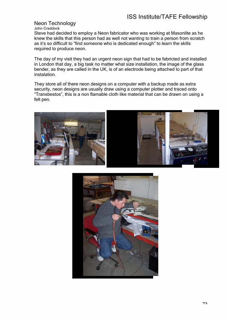
ISS Institute/TAFE Fellowship Neon Technology John Craddock
73
Steve had decided to employ a Neon fabricator who was working at Masonlite as he knew the skills that this person had as well not wanting to train a person from scratch as it’s so difficult to “find someone who is dedicated enough” to learn the skills required to produce neon. The day of my visit they had an urgent neon sign that had to be fabricted and installed in London that day, a big task no matter what size installation, the image of the glass bender, as they are called in the UK, is of an electrode being attached to part of that instalation. They store all of there neon designs on a computer with a backup made as extra security, neon designs are usually draw using a computer plotter and traced onto “Transbestos”, this is a non flamable cloth like material that can be drawn on using a felt pen.

ISS Institute/TAFE Fellowship Neon Technology John Craddock
74
Industry visits Kemps Neon Geoff Clarke Unit 2 Matrix Court Middleton Grove Leeds LS11 5WB www.kempsneon.com Firstly I have to give many thanks to Geoff Clarke at Kemps for his wiliness to share his experience and knowledge of cold cathode lighting with me, I would urge people reading this report to visit Kemps web site as it is one of the best sites I’ve seen with some fantastic examples of their work on display, as shown below. Kemps is one of very few companies in the UK specifically set up for neon fabrication in all its forms, Signage, Architectural, and Lighting and as an Art form.

ISS Institute/TAFE Fellowship Neon Technology John Craddock
75
The Neon workshop at Kemps was specifically designed to meet the requirements for producing Neon of the highest quality; this included ensuring sufficient ventilation, (as with a number of burners working for many hours it’s possible to rob oxygen from the air), adequate lighting, movable burners to allow for flexibility when working on sections of various size and shape. Also providing a large workshop helps reduce the level of noise that is produced from the burners as they run on a pressurised gas mixture, the level of noise in a neon workshop can be surprisingly high. Each of the Neon fabricators is provided with a sufficient work space to help reduce breakages and accidents and to allow for large sections of tube to be produced safely.
Kemps have a large workspace for their neon fabricators, with ample
ventilation good lighting.
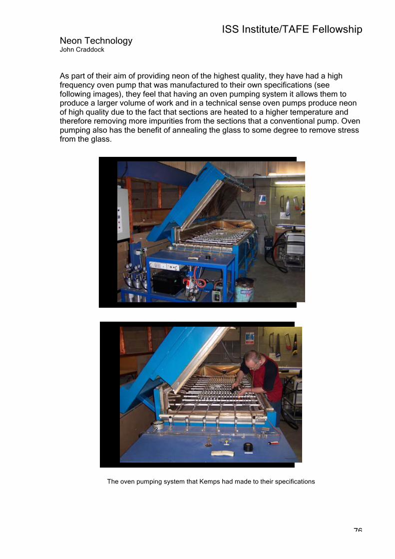
ISS Institute/TAFE Fellowship Neon Technology John Craddock
76
As part of their aim of providing neon of the highest quality, they have had a high frequency oven pump that was manufactured to their own specifications (see following images), they feel that having an oven pumping system it allows them to produce a larger volume of work and in a technical sense oven pumps produce neon of high quality due to the fact that sections are heated to a higher temperature and therefore removing more impurities from the sections that a conventional pump. Oven pumping also has the benefit of annealing the glass to some degree to remove stress from the glass.
The oven pumping system that Kemps had made to their specifications

ISS Institute/TAFE Fellowship Neon Technology John Craddock
77
This section of tube is being heated using a ribbon burner.
The same section being laid down over a design that has been
drawn on “Transbestos”, at this point the tube will be carefully
bent to the required shape.
This is the area that is designed to age the sections prior to installation.
This area has an optic sensor that
turns off the power supply if someone accidentally walks into the
area in case the tubes shatter.
A view of the electrical section used for fitting high voltage wiring
and the installation of flashers, DMX control systems and faders.

ISS Institute/TAFE Fellowship Neon Technology John Craddock
78
Industry visit Hitech Signs Michael Dally 65-81 Port Dundas Industrial Estate Glasgow G4 OLA Scotland www.hitechsigns.co.uk I have to say that in all my time working in the Sign Industry and visiting sign companies in Australia over many years I have only seen a few companies that are as well planed and organised as Hitech Signs in Glasgow. After entering the reception area I was instantly aware that this was a very professional company, with many of their clients represented in a display in their large reception area, this enabled prospective clients to view a sample of the type of work that Hitech Signs could offer.
A corner of the reception area at Hitech Signs in Glasgow I was greeted by the company owner and Managing Director Michael Dally, it was refreshing to be able to exchange information on many aspects of our industry and to find someone who allowed me to have open access of the workshop to talk to all of the people employed there. The following quote was taken from their web page:
“Since our foundation in 1983 we have been a family owned business with one simple aim: to become one of the UK's leading sign companies.”
From what I saw at Hitech Signs they are well on their way to achieving that goal.

ISS Institute/TAFE Fellowship Neon Technology John Craddock
79
I asked Managing Director Michael Dally what was the key to the success of Hitech Signs, his reply was refreshing and informative: From the beginning of the company Michael’s philosophy has been to provide attention to detail at every step of the way from the client brief, the critical design stage and the manufacturing process, this as well as a the use of only the finest quality materials that are available to be used in production. This is followed up by quality installation and service to complete the package that is offered to clients. The other part of this outstanding company is its team work; this has been built on over many years with a commitment to offering staff a career path and training in the latest technologies in the industry. This is coupled with friendly staff who offer their clients a personal touch that can be so lacking in many companies today they have a commitment to listen to what their clients are seeking and offer recommendations from their experience and knowledge. This philosophy has led to many long lasting business associations with major corporations in the UK and Ireland.

ISS Institute/TAFE Fellowship Neon Technology John Craddock
80
Hitech Signs work with a wide range of materials such as, Neon, decorative glass, Acrylic, Aluminium, and Stainless steel. All of these materials are used to create a wide variety of high quality signage, for example, Neon, Channel lettering, Engraved signage, Vinyl, Computer routed designs, and digital printed designs.
The Neon component has been part of Hitech Signs since it started business in 1984, both Michael Dally and George Swift (who is their Neon fabricator), have a background in neon from their previous employers and have a close working relationship as well as being friends as well. Hitech have chosen to use a pumping station instead of an oven pump as they believe it to be a tried and trusted method to produce neon, George told me that over the years he has been bending glass he has had very few failures and that Hitech have a strong emphasis on quality signage, of all types, for their customers as part of the Hitech philosophy. If they thought an oven pump would work better than the current system being used they would think of changing over but feel completely satisfied with the work being produced, he did stress the importance of maintenance of the pumping station as being essential to quality work to ensure that as many impurities as possible are removed from the sections prior to filling. The other area that he felt was important was the installation to ensure that there was no stress on the sections of glass, they therefore have a wide range of tube supports to suit various applications and requirements.

ISS Institute/TAFE Fellowship Neon Technology John Craddock
81
The designs that George works with are all prepared on “Transbestos” as that the sections can be laid down on the work bench to help form the desired shape, many of the designs are stored on a data base and plotted only when they are required.
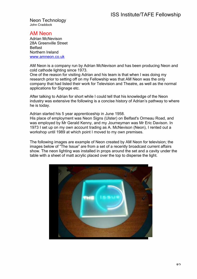
ISS Institute/TAFE Fellowship Neon Technology John Craddock
82
AM Neon Adrian McNevison 28A Greenville Street Belfast Northern Ireland www.amneon.co.uk AM Neon is a company run by Adrian McNevison and has been producing Neon and cold cathode lighting since 1973. One of the reason for visiting Adrian and his team is that when I was doing my research prior to setting off on my Fellowship was that AM Neon was the only company that had listed their work for Television and Theatre, as well as the normal applications for Signage etc. After talking to Adrian for short while I could tell that his knowledge of the Neon industry was extensive the following is a concise history of Adrian’s pathway to where he is today. Adrian started his 5 year apprenticeship in June 1958. His place of employment was Neon Signs (Ulster) on Belfast's Ormeau Road, and was employed by Mr Gerald Kenny, and my Journeyman was Mr Eric Davison. In 1973 I set up on my own account trading as A. McNevison (Neon), I rented out a workshop until 1989 at which point I moved to my own premises. The following images are example of Neon created by AM Neon for television; the images below of “The Issue” are from a set of a recently broadcast current affairs show. The neon lighting was installed in props around the set and a cavity under the table with a sheet of matt acrylic placed over the top to disperse the light.

ISS Institute/TAFE Fellowship Neon Technology John Craddock
83
“The Issue” set seen from a different angle
These next set of images are more examples of work from Adrian, this time for a chat show called “May N You”. The set appeared as a back yard which transformed into a stage area with the aid of Neon lighting, the lighting was used to uplift drainage guttering, a hose reel, bicycle, stage steps and various wall features.
Scenes from the chat show “May N You”
Summary/Recommendations

ISS Institute/TAFE Fellowship Neon Technology John Craddock
84
How to bring Neon into a modern environment? As can be seen from the previous information neon has been created much the same way as it was a century ago, sure there have been improvements in the quality of the materials used to construct a working piece of neon, such as the quality of the glass, and improved electrodes. But without imagination used in the design stage it could be seen as just another form of lighting to compete with the fast evolving LED’s for example. So how should the neon industry react? My answer would be by being more creative! With the new generation of electronics, the way neon behaves can be programmed to meet modern applications, see attached CD containing video of the “New World Centre” in Hong Kong as an example of what could be achieved. With creative companies such as “Mode Lighting” in the UK making a wide range of dimmable transformers and more importantly DMX units, these are digital data protocol devices that allow for mixing of neon tube colour to produce all the colours of the rainbow using the same principle as RGB televisions or computer screens.
With the new generation of electronic controllers it is relatively easy to create a program using a computer and download it to the controller to produce gentle crossfading of colours to something more suited to a discotheque.
These images show the imaginative
ways in which neon can be used for
creating an attractive and
modern look; neon doesn’t need to just
be used for Signage.

ISS Institute/TAFE Fellowship Neon Technology John Craddock
85
Note the neat and tidy way that the tube ends have been hidden in the image on the right, clever and effective thinking in practice. Digital protocol was introduced around 1990 to control complex lighting effects for theatrical and entertainment settings and has now found its way into the area of Architectural lighting. With this technology the lighting designer can create a lighting sequence or sequences that can be easily recalled using a hand held controller.
Mode Lighting “Colourtran-350”, note the input for the DMX unit and the three separate output channels for the Red, Green and Blue lights used in combination to produce colour fades.

ISS Institute/TAFE Fellowship Neon Technology John Craddock
86
Summary/Recommendations Training It would appear that the Neon component of the Sign Industry is fragmented, as to the best of my knowledge and after making enquires there is no Neon Association in Australia or the United Kingdom for that matter. This is not to say that their aren’t progressive companies producing quality neon and using it in new and exciting ways, such as the companies I visited in the UK, but there appears to be no single body working together to promote neon as a career for people looking to work in a highly skilled job such as neon fabricating. As far as training goes, there is no Neon School in the Southern Hemisphere yet after my visit to the Hong Kong and to see how neon is used on such a vast scale there must be a lot of people working in the industry, and with so many of our Asian and New Zealand neighbours being in such relative close proximity to Australia, perhaps that is an untapped market for training. Not only could this apply to Asia but to the Middle East and Russia as well, while visiting Masonlite I was told that they are the two countries where export has grown at a rapid rate, again both of these markets only have the British School of Neon that can offer training in the United Kingdom, I believe these are markets that could be looked at in addition to Asia and New Zealand. With world markets putting an ever increasing emphasis on having trained and qualified staff, Victoria could take on the role of providing RPL, (Recognition of Prior Learning), to people already working in the industry. The other point of concern is finding the right person to teach students the full range of skills required to become competent as a neon fabricator, many of the people producing neon have told me that even after five or six months full time tuition that a person would require at least four or five years working in the field to become a true master. Many companies have staff who are only involved in one aspect of neon fabrication, i.e. one person that bends the tube and attaches the electrodes another that carries out the pumping and bombarding followed by an electrician to calculate transformer requirements and produce the necessary cabling and others to do on site installation. Other issues in regard to training: So who has a vested interest in training? TAFE institutes around Australia could take up the challenge to set up and provide training and assessment for people in the neon industry, this would provide a much needed service to the industry an in turn the industry would have a skilled workforce that had quality training provided in Australia rather than travel overseas.

ISS Institute/TAFE Fellowship Neon Technology John Craddock
87
Industry training and education: There are some industry bodies that could benefit from an understanding of the broad applications that neon can be used for such as, architects and interior designers. Some of these industry groups are: RAIA Royal Australian Institute of Architects www.architecture.com.au DIA Design Institute Australia www.dia.org.au AGDA Australian Graphic Design Association www.agda.asn.au Some of the areas that I believe must be taught as part of the training to become qualified as a neon fabricator is based on “Design” principals: Areas such as: COLOUR TYPOGRAPHY STREET SCAPES GRAPHIC DESIGN INTERIOR DESIGN MARKETING Colour With the ability to create neon in almost any colour it is vital to have an understanding of how colour works in setting moods and creating an atmosphere, no only for signage but for architectural and interior lighting applications. Typography This is and area close to my heart as I have admired and studied Typography for many years, when designing signage for neon applications there are certain technical elements that must be understood by the designer and the fabricator. These can be, for example, the diameter of the tube required to produce the design may not produce the desired lighting effect, and also the design if too complicated may increase the production time dramatically. Street scapes One of the things that struck me in the United Kingdom was how neon was incorporated into villages and cities that had medieval buildings and structures; this was achieved by the designer having an understanding of the two areas that I have touched on, that is, colour and typography. Without and understanding of these fundamental elements of the design process neon would look brash and well out of place. This principal would apply in other situations where something bright and bold would be required such as an amusement park or night club.
ISS Institute/TAFE Fellowship Neon Technology John Craddock
88
Graphic Design Again a cornerstone to becoming the professional neon fabricator and designer, this area would encompass the elements mentioned above as well as gaining an insight into proportion and balance in design. Interior design With the modern electronic control systems that are available to alter how neon can be used as a lighting form I see the use of neon for restaurants, galleries, and night clubs becoming the norm. People studying interior design at the moment may not be being educated in the amazing possibilities that neon can offer. Marketing The neon industry as a whole needs to ensure that there is a marketing philosophy established to promote the use of neon in all the areas that I have mentioned previously. It is one thing to be a master designer and fabricator but if there is not marketing aspect to your work then the opportunities to sell your skills may be lost. I feel that it would be very difficult to give an estimate of the numbers of students that could be in the market for training but you would have to assume it to be substantial. What would be required is prolonged aggressive marketing as well as educating people about the neon industry as most people just have no idea how neon in any form is produced, this was underlined by the presentation I gave to a group of 250 people from the TAFE staff at Victoria University, after my presentation people were coming up to me and telling me that they had never stopped and thought “how was that made” or that was interesting “as I had no idea that there even was an industry making neon” Costs involved in setting up a Neon workshop could be substantial, depending on the number of students, type, and the scale of workshop that was decided on keeping in mind the amount of heat generated and the lose of oxygen in a workshop with multiple burners operating. Also the material costs could be high as much of the pieces produced while learning to bend glass would end up being thrown in the bin, experienced benders make it look so easy but believe me it’s requires a high degree of practice and patience even to produce a bend of average quality. I haven’t gone into gathering prices as I would need to gauge the level of support from industry suppliers and distributors and I felt that was best left until it was agreed to look at the feasibility of such an undertaking. With the current climate to encourage departments to be more entrepreneurial and the benefits gained from providing training for overseas fee paying students it may be worth looking into further.

ISS Institute/TAFE Fellowship Neon Technology John Craddock
89
What is the role of the ISS? The role of the ISS is to act as a vehicle to open up areas that otherwise would not normally be available to designers in many areas. To be able to facilitate conferences to pass on the information that ISS recipients have gained on their Fellowship journey, this in turn will inspire others to use the knowledge passed on to them to become leaders in their chosen field. I have said from the outset of my Fellowship that I feel that I have become an advocate for the Neon Industry and I see my role to promote the technology and the design aspects of this wonderful light form. I hope to be seen as an industry speaker and to be able to showcase the skills and knowledge that I have gained during my Fellowship. I hope you have enjoyed reading my report and would appreciate any feedback or comments that you would like make.