Embed Size (px)
Citation preview
ISOBUS Hydraulic Down Force
At a Glance—Universal TerminalPlanter Average Run Screen
Gauge Wheel Load Bar Graph
Status Indicator
blue = active
yellow = inactive
Input Hydraulic Pressure
Run Screen
Down Force Adjustment
Settings
Diagnostices
Tools
Automatic Control
Manual Control
Supplemental Force Bar Graph
Gauge Wheel Load Bar Graph
Planter Average
Supplemental Force
Gauge Wheel Load
Gauge Wheel Load Settings
Gauge Wheel Load
Medium
Row
AUTO
1PN 2006027–ENG Rev. H
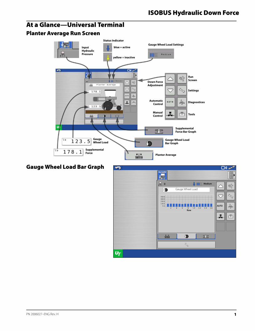
Supplemental Force Bar Graph
At a Glance – With Ag Leader InCommand 1200Gauge Wheel Load Map(A) Gauge Wheel Load Legend
(B) Mapped Gauge Wheel Load
÷ NOTE!: Planter rows that do not have a gauge wheel sensor installed will not map or log gauge wheel load for that row.
Supplemental Force
Medium
Channel
AUTO
2
ISOBUS Hydraulic Down Force
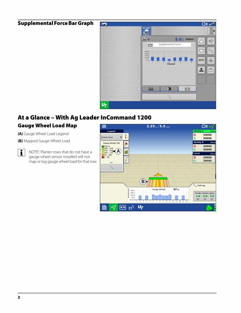
Supplemental Down Force Map(A) Supplemental Down Force Legend
(B) Mapped Supplemental Down Force
÷ NOTE!: Mapped Supplemental Force will reflect the ISOBUS Down Force configuration setup.
Bar GraphTapping subsequently will toggle the bar graph between the following graphs. (Seed placement performance graphs will also appear if a seed/planter monitor module is installed)
Supplemental Down Force and Gauge Wheel Load graphs are available in the Advanced Seed Monitoring screen. (This screen will only be available when an Ag Leader Seed Tube Monitoring Module is installed).
3 PN 2006027–ENG Rev. H
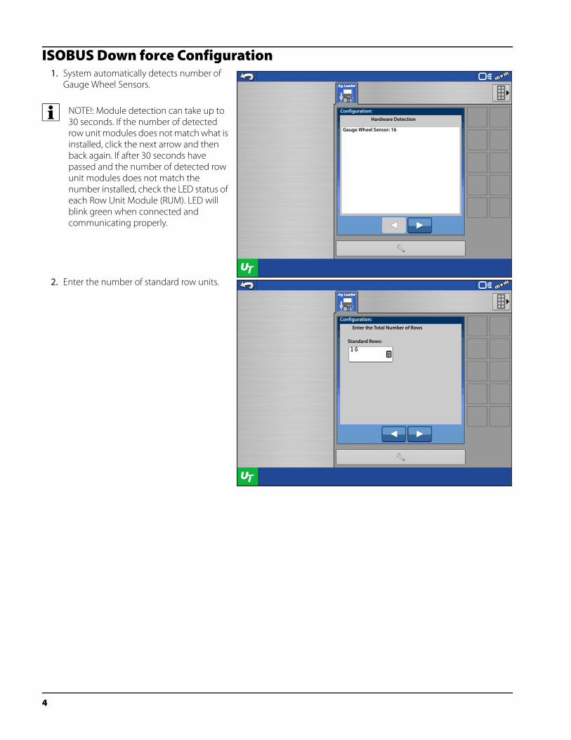
ISOBUS Down force Configuration1. System automatically detects number of
Gauge Wheel Sensors.
÷ NOTE!: Module detection can take up to 30 seconds. If the number of detected row unit modules does not match what is installed, click the next arrow and then back again. If after 30 seconds have passed and the number of detected row unit modules does not match the number installed, check the LED status of each Row Unit Module (RUM). LED will blink green when connected and communicating properly.
2. Enter the number of standard row units.
Configuration:
Hardware Detection
Gauge Wheel Sensor: 16
Configuration:
Enter the Total Number of Rows
Standard Rows:
4
ISOBUS Hydraulic Down Force
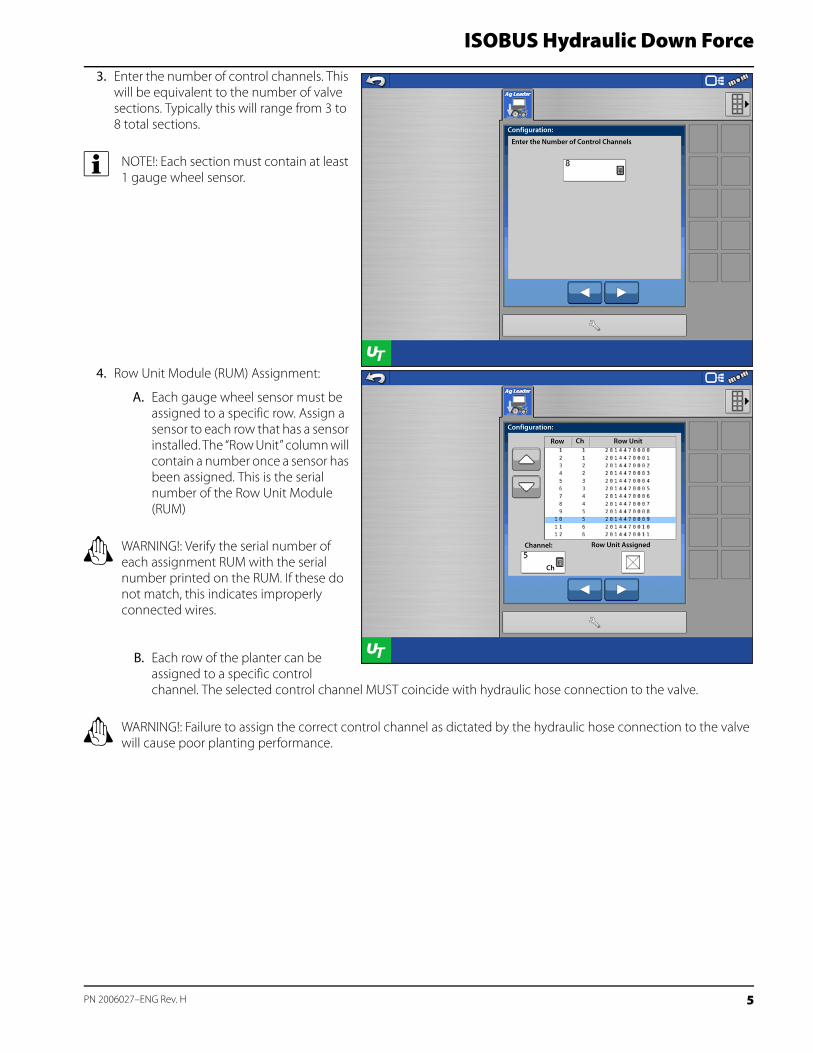
3. Enter the number of control channels. This will be equivalent to the number of valve sections. Typically this will range from 3 to 8 total sections.
÷ NOTE!: Each section must contain at least 1 gauge wheel sensor.
4. Row Unit Module (RUM) Assignment:
A. Each gauge wheel sensor must be assigned to a specific row. Assign a sensor to each row that has a sensor installed. The “Row Unit” column will contain a number once a sensor has been assigned. This is the serial number of the Row Unit Module (RUM)
± WARNING!: Verify the serial number of each assignment RUM with the serial number printed on the RUM. If these do not match, this indicates improperly connected wires.
B. Each row of the planter can be assigned to a specific control channel. The selected control channel MUST coincide with hydraulic hose connection to the valve.
± WARNING!: Failure to assign the correct control channel as dictated by the hydraulic hose connection to the valve will cause poor planting performance.
Configuration:
Enter the Number of Control Channels
Configuration:
Row Ch Row Unit
Channel:
Ch
Row Unit Assigned
5 PN 2006027–ENG Rev. H
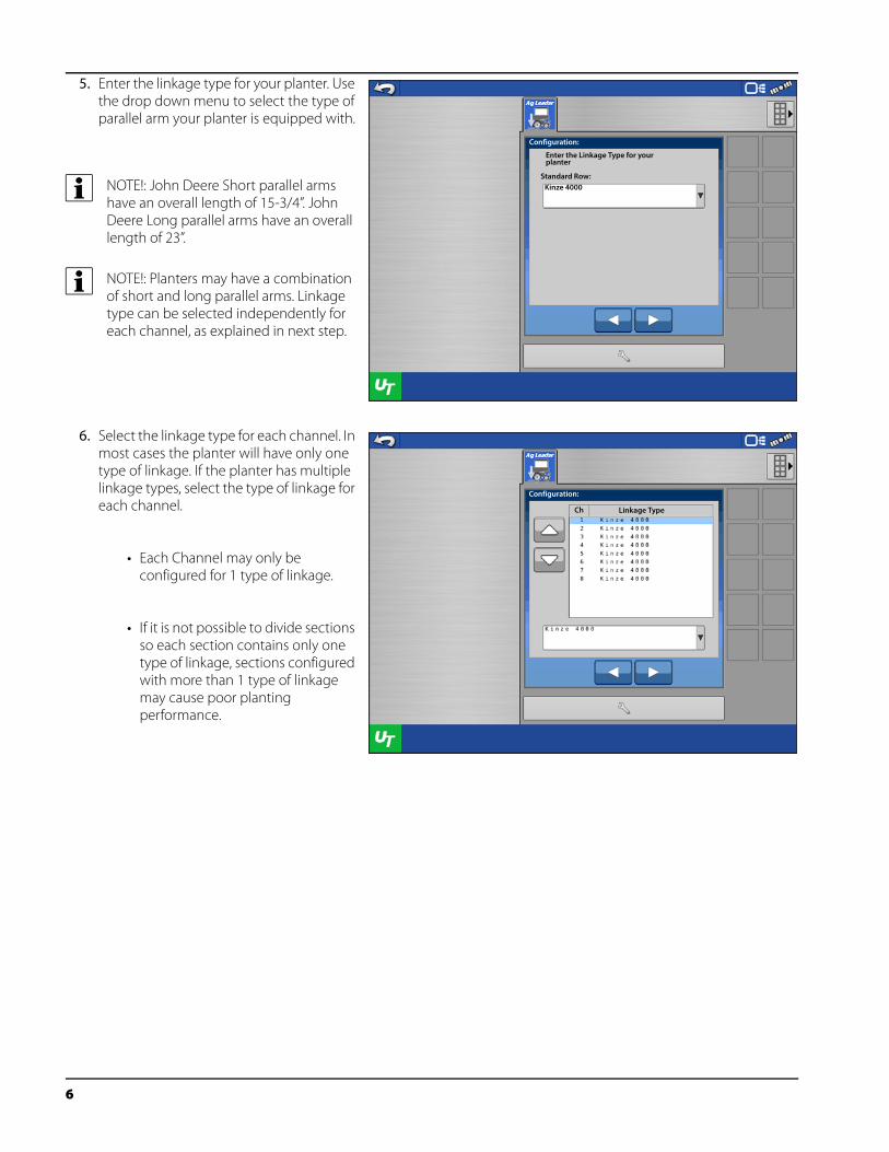
5. Enter the linkage type for your planter. Use the drop down menu to select the type of parallel arm your planter is equipped with.
÷ NOTE!: John Deere Short parallel arms have an overall length of 15-3/4”. John Deere Long parallel arms have an overall length of 23”.
÷ NOTE!: Planters may have a combination of short and long parallel arms. Linkage type can be selected independently for each channel, as explained in next step.
6. Select the linkage type for each channel. In most cases the planter will have only one type of linkage. If the planter has multiple linkage types, select the type of linkage for each channel.
• Each Channel may only be configured for 1 type of linkage.
• If it is not possible to divide sections so each section contains only one type of linkage, sections configured with more than 1 type of linkage may cause poor planting performance.
Configuration:
Enter the Linkage Type for your planter
Kinze 4000Standard Row:
Configuration:
Ch Linkage Type
6
ISOBUS Hydraulic Down Force
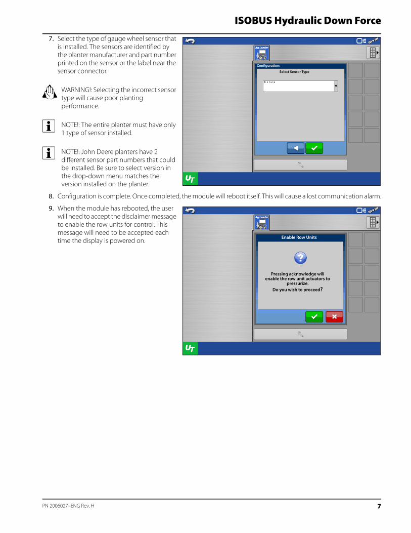
7. Select the type of gauge wheel sensor that is installed. The sensors are identified by the planter manufacturer and part number printed on the sensor or the label near the sensor connector.
± WARNING!: Selecting the incorrect sensor type will cause poor planting performance.
÷ NOTE!: The entire planter must have only 1 type of sensor installed.
÷ NOTE!: John Deere planters have 2 different sensor part numbers that could be installed. Be sure to select version in the drop-down menu matches the version installed on the planter.
8. Configuration is complete. Once completed, the module will reboot itself. This will cause a lost communication alarm.
9. When the module has rebooted, the user will need to accept the disclaimer message to enable the row units for control. This message will need to be accepted each time the display is powered on.
Configuration:
Select Sensor Type
Pressing acknowledge willenable the row unit actuators to
pressurize.Do you wish to proceed?
Enable Row Units
7 PN 2006027–ENG Rev. H
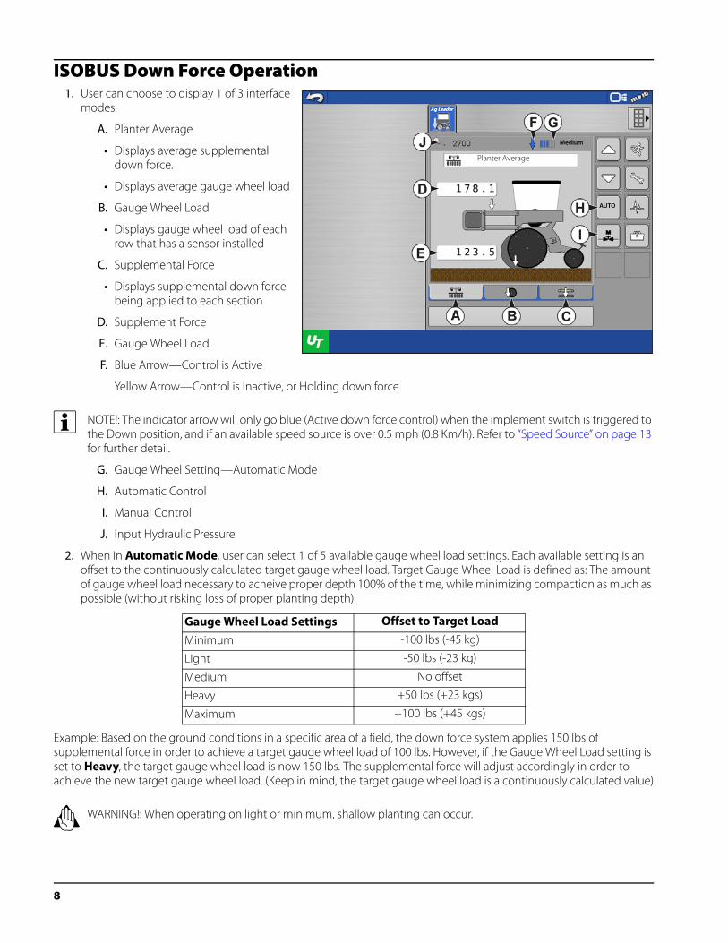
ISOBUS Down Force Operation1. User can choose to display 1 of 3 interface
modes.
A. Planter Average
• Displays average supplemental down force.
• Displays average gauge wheel load
B. Gauge Wheel Load
• Displays gauge wheel load of each row that has a sensor installed
C. Supplemental Force
• Displays supplemental down force being applied to each section
D. Supplement Force
E. Gauge Wheel Load
F. Blue Arrow—Control is Active
Yellow Arrow—Control is Inactive, or Holding down force
÷ NOTE!: The indicator arrow will only go blue (Active down force control) when the implement switch is triggered to the Down position, and if an available speed source is over 0.5 mph (0.8 Km/h). Refer to “Speed Source” on page 13 for further detail.
G. Gauge Wheel Setting—Automatic Mode
H. Automatic Control
I. Manual Control
J. Input Hydraulic Pressure
2. When in Automatic Mode, user can select 1 of 5 available gauge wheel load settings. Each available setting is an offset to the continuously calculated target gauge wheel load. Target Gauge Wheel Load is defined as: The amount of gauge wheel load necessary to acheive proper depth 100% of the time, while minimizing compaction as much as possible (without risking loss of proper planting depth).
Example: Based on the ground conditions in a specific area of a field, the down force system applies 150 lbs of supplemental force in order to achieve a target gauge wheel load of 100 lbs. However, if the Gauge Wheel Load setting is set to Heavy, the target gauge wheel load is now 150 lbs. The supplemental force will adjust accordingly in order to achieve the new target gauge wheel load. (Keep in mind, the target gauge wheel load is a continuously calculated value)
± WARNING!: When operating on light or minimum, shallow planting can occur.
Gauge Wheel Load Settings Offset to Target Load
Minimum -100 lbs (-45 kg)
Light -50 lbs (-23 kg)
Medium No offset
Heavy +50 lbs (+23 kgs)
Maximum +100 lbs (+45 kgs)
Medium
Planter Average
AUTO
8
ISOBUS Hydraulic Down Force
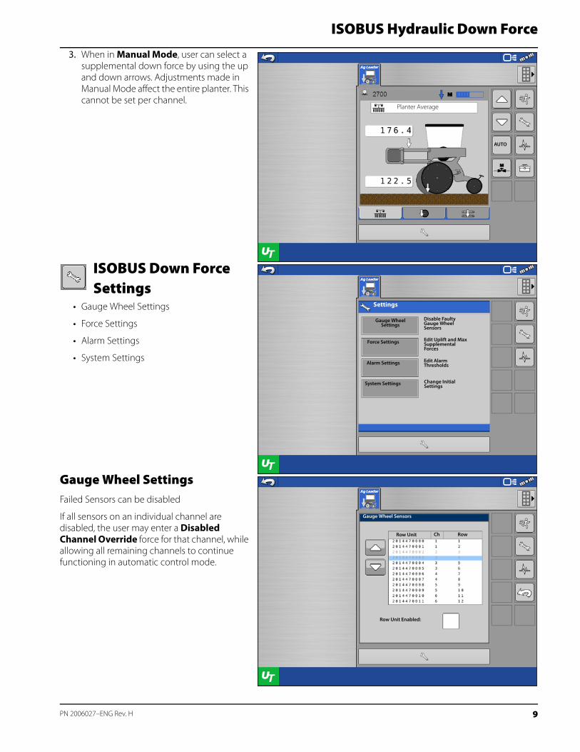
3. When in Manual Mode, user can select a supplemental down force by using the up and down arrows. Adjustments made in Manual Mode affect the entire planter. This cannot be set per channel.
ISOBUS Down Force Settings
• Gauge Wheel Settings
• Force Settings
• Alarm Settings
• System Settings
Gauge Wheel SettingsFailed Sensors can be disabled
If all sensors on an individual channel are disabled, the user may enter a Disabled Channel Override force for that channel, while allowing all remaining channels to continue functioning in automatic control mode.
Planter Average
AUTO
Gauge Wheel Settings
Settings
Force Settings
Alarm Settings
System Settings
Disable Faulty Gauge Wheel Sensors
Edit Uplift and Max Supplemental Forces
Edit Alarm Thresholds
Change Initial Settings
Gauge Wheel Sensors
ChRow Unit Row
Row Unit Enabled:
9 PN 2006027–ENG Rev. H
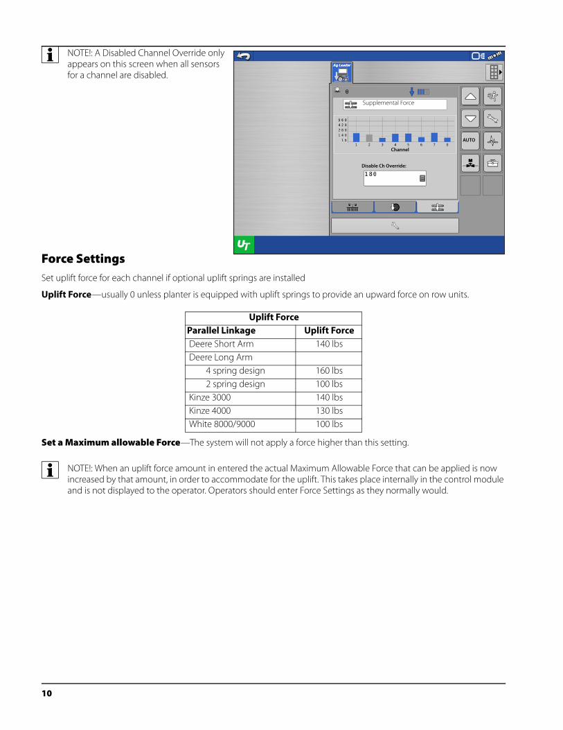
÷ NOTE!: A Disabled Channel Override only appears on this screen when all sensors for a channel are disabled.
Force SettingsSet uplift force for each channel if optional uplift springs are installed
Uplift Force—usually 0 unless planter is equipped with uplift springs to provide an upward force on row units.
Set a Maximum allowable Force—The system will not apply a force higher than this setting.
÷ NOTE!: When an uplift force amount in entered the actual Maximum Allowable Force that can be applied is now increased by that amount, in order to accommodate for the uplift. This takes place internally in the control module and is not displayed to the operator. Operators should enter Force Settings as they normally would.
Uplift ForceParallel Linkage Uplift Force Deere Short Arm 140 lbs Deere Long Arm 4 spring design 160 lbs 2 spring design 100 lbs Kinze 3000 140 lbs Kinze 4000 130 lbs White 8000/9000 100 lbs
Supplemental Force
AUTO
Channel
Disable Ch Override:
10
ISOBUS Hydraulic Down Force
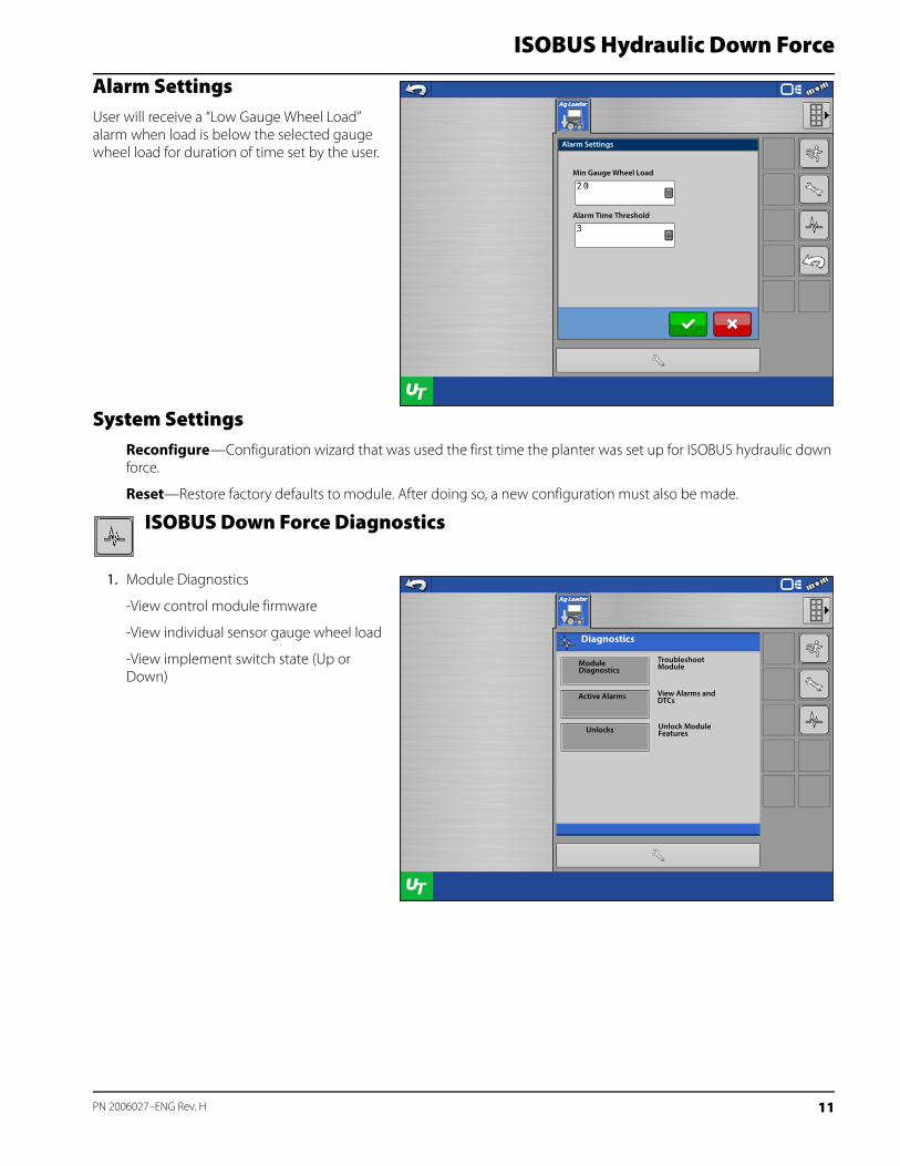
Alarm SettingsUser will receive a “Low Gauge Wheel Load” alarm when load is below the selected gauge wheel load for duration of time set by the user.
System SettingsReconfigure—Configuration wizard that was used the first time the planter was set up for ISOBUS hydraulic down force.
Reset—Restore factory defaults to module. After doing so, a new configuration must also be made.
ISOBUS Down Force Diagnostics
1. Module Diagnostics
-View control module firmware
-View individual sensor gauge wheel load
-View implement switch state (Up or Down)
Alarm Settings
Min Gauge Wheel Load
Alarm Time Threshold
Module Diagnostics
Diagnostics
Active Alarms
Unlocks
Troubleshoot Module
Unlock Module Features
View Alarms and DTCs
11 PN 2006027–ENG Rev. H
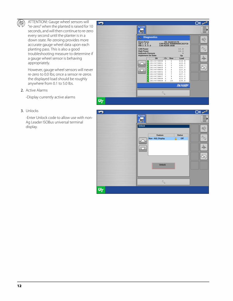
μ ATTENTION!: Gauge wheel sensors will “re-zero” when the planted is raised for 10 seconds, and will then continue to re-zero every second until the planter is in a down state. Re-zeroing provides more accurate gauge wheel data upon each planting pass. This is also a good troubleshooting measure to determine if a gauge wheel sensor is behaving appropriately.
However, gauge wheel sensors will never re-zero to 0.0 lbs; once a sensor re-zeros the displayed load should be roughly anywhere from 0.1 to 5.0 lbs.
2. Active Alarms
-Display currently active alarms
3. Unlocks
-Enter Unlock code to allow use with non-Ag Leader ISOBus universal terminal display.
Diagnostics
Down ForceSW: 1 . 4 . 0HW: 3 . 0 . 0 . 0
SN: 2620010179CAN Name: A06884000C2027C8CAN ADDR: 0X08
CAN PowerHigh PowerHydraulic PressureImplement Sw State Up
SN Ch Row Load
Unlock
Feature Status
Non - AGL Display Off
Unlock
12
ISOBUS Hydraulic Down Force
ISOBUS Down Force Tools
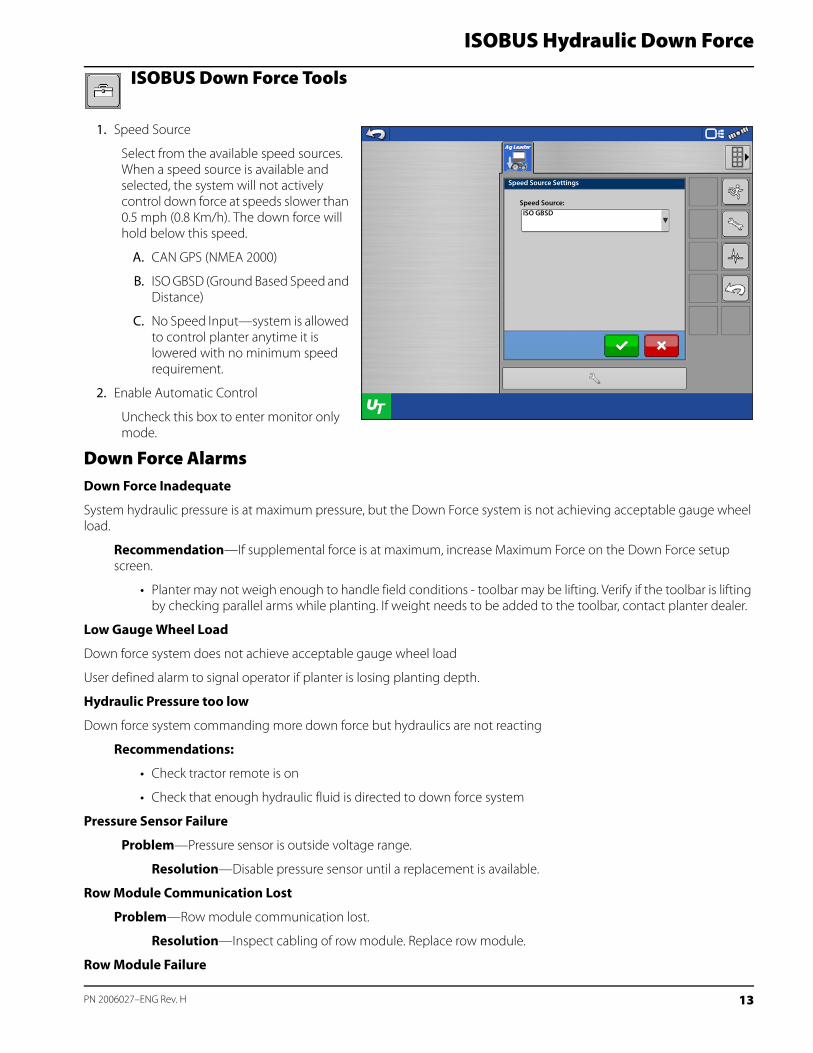
1. Speed Source
Select from the available speed sources. When a speed source is available and selected, the system will not actively control down force at speeds slower than 0.5 mph (0.8 Km/h). The down force will hold below this speed.
A. CAN GPS (NMEA 2000)
B. ISO GBSD (Ground Based Speed and Distance)
C. No Speed Input—system is allowed to control planter anytime it is lowered with no minimum speed requirement.
2. Enable Automatic Control
Uncheck this box to enter monitor only mode.
Down Force AlarmsDown Force Inadequate
System hydraulic pressure is at maximum pressure, but the Down Force system is not achieving acceptable gauge wheel load.
Recommendation—If supplemental force is at maximum, increase Maximum Force on the Down Force setup screen.
• Planter may not weigh enough to handle field conditions - toolbar may be lifting. Verify if the toolbar is lifting by checking parallel arms while planting. If weight needs to be added to the toolbar, contact planter dealer.
Low Gauge Wheel Load
Down force system does not achieve acceptable gauge wheel load
User defined alarm to signal operator if planter is losing planting depth.
Hydraulic Pressure too low
Down force system commanding more down force but hydraulics are not reacting
Recommendations:
• Check tractor remote is on
• Check that enough hydraulic fluid is directed to down force system
Pressure Sensor Failure
Problem—Pressure sensor is outside voltage range.
Resolution—Disable pressure sensor until a replacement is available.
Row Module Communication Lost
Problem—Row module communication lost.
Resolution—Inspect cabling of row module. Replace row module.
Row Module Failure
Speed Source Settings
Speed Source:ISO GBSD
13 PN 2006027–ENG Rev. H
Problem—Row module is not sensing inputs. Row module is power cycling at intervals of less than 2 seconds
Resolution—Swap module with different row. If problem follows, replace module. If problem exists on same row, inspect or replace load sensor.
How to use Manual OverrideManual Override of the control valve may be needed if all electronic control of the Down Force System is lost, or the operating display becomes unusable. Manual Override allows the Down Force system to apply a constant force in order to achieve planting depth (similar to down force springs). If the need arises to put the control valve into Manual Override, follow these steps.
Steps:
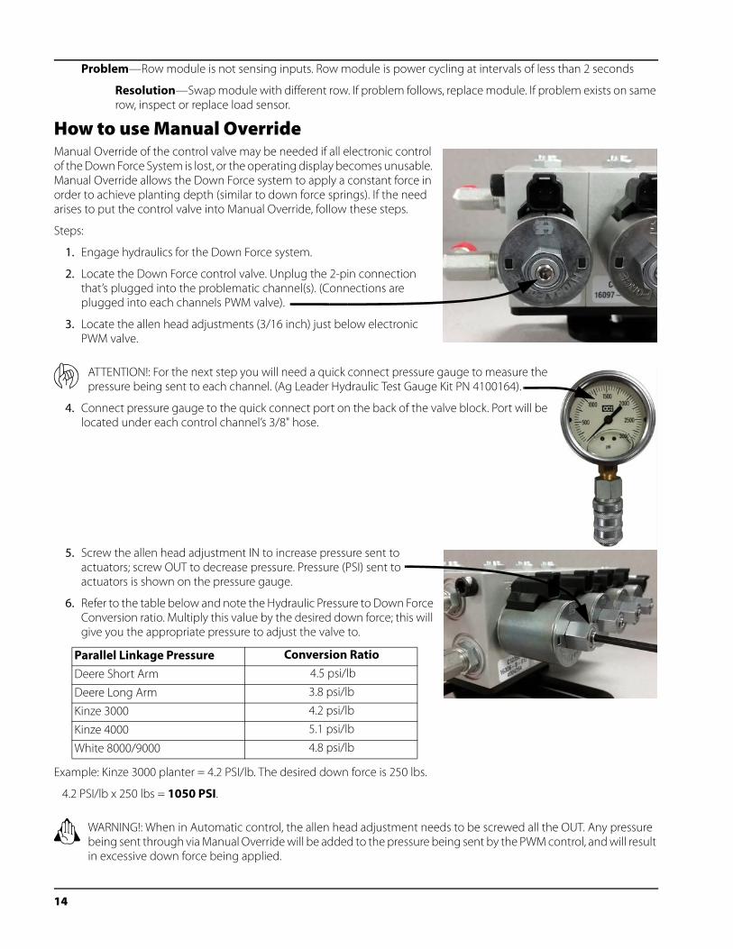
1. Engage hydraulics for the Down Force system.
2. Locate the Down Force control valve. Unplug the 2-pin connection that’s plugged into the problematic channel(s). (Connections are plugged into each channels PWM valve).
3. Locate the allen head adjustments (3/16 inch) just below electronic PWM valve.
μ ATTENTION!: For the next step you will need a quick connect pressure gauge to measure the pressure being sent to each channel. (Ag Leader Hydraulic Test Gauge Kit PN 4100164).
4. Connect pressure gauge to the quick connect port on the back of the valve block. Port will be located under each control channel’s 3/8" hose.
5. Screw the allen head adjustment IN to increase pressure sent to actuators; screw OUT to decrease pressure. Pressure (PSI) sent to actuators is shown on the pressure gauge.
6. Refer to the table below and note the Hydraulic Pressure to Down Force Conversion ratio. Multiply this value by the desired down force; this will give you the appropriate pressure to adjust the valve to.
Example: Kinze 3000 planter = 4.2 PSI/lb. The desired down force is 250 lbs.
4.2 PSI/lb x 250 lbs = 1050 PSI.
± WARNING!: When in Automatic control, the allen head adjustment needs to be screwed all the OUT. Any pressure being sent through via Manual Override will be added to the pressure being sent by the PWM control, and will result in excessive down force being applied.
Parallel Linkage Pressure Conversion Ratio
Deere Short Arm 4.5 psi/lb
Deere Long Arm 3.8 psi/lb
Kinze 3000 4.2 psi/lb
Kinze 4000 5.1 psi/lb
White 8000/9000 4.8 psi/lb
14
ISOBUS Hydraulic Down Force
FAQ-What should my input hydraulic pressure (PSI) be set at?
2500 to 3000 PSI (with the vehicle hydraulic source set to max flow)
-Where do I plug in an implement switch(s)?
Into the Implement Switch Module(s).
-What if I don’t have any free SCV connections for the down force valve?
Teeing into existing lines is acceptable. Do not tee into the vacuum fan line if adjusting fan RPM on the tractor with a knob or dial. Teeing into the line before a flow limiter on the planter would be acceptable. Teeing into the hydraulic drive supply line would be the best option. Do not tee into Rawson Drive supply line.
-What if my hydraulic oil gets too hot?
Ag Leader sells a Load Sense kit (P/N 4101225) to help manage oil temperatures. Note: This system will not help if using SCV to control hydraulic drives. In this case, an auxiliary oil cooler may need to be installed.
-What if my hydraulic actuator does not extend far enough to reach the lower bracket with row unit at bottom travel?
Purchase one spacer kit (P/N 4101201) per row. This will install at the bottom of the ram. (Commonly used on John Deere long parallel arms)
-My Kinze 3000 planter has rows that are offset 4” back, causing the upper actuator bracket to not line up with the lower actuator bracket.
Purchase one spacer kit (P/N 4101204) per row. This will move the upper bracket 4” rearward.
-Why is the gauge wheel load bar graph constantly spiking and then going to 0?
This can happen if control channel lines are routed incorrectly. Ensure channel components (hydraulic hoses, control valve cable, gauge wheel sensor wiring) are installed per the instructions.
-Why does the system need 3 hydraulic lines (Pressure, Return and Tank)
Under normal operation, pressure in the down force system is increased through the Pressure line and relieved through the Return line. When the planter runs over a terrace or a water way, the access pressure is released through the Tank line. All three lines MUST be connected.
-What happens if my Pressure and Return hoses are connected backwards on my Hydraulic Down Force valve block?
If the Pressure and Return hoses are connected backwards on the Hydraulic Down Force valve block, the hydraulic flow will be sent directly to the channels connected to the valve block. Once this happens, the actuators on all of the channels will be applying max supplemental force. On the screen of the controlling display, this may likely result in very high gauge wheel load. This will occur on all variations of valve blocks that Ag Leader supports.
-What is a CAN Repeater Module; and when is it required?
A CAN Repeater Module is a component that is used on Ag Leaders ISOBUS Hydraulic Down Force system. It is only installed on systems with a Local CANBUS that exceeds a certain length. The modules purpose is to “repeat” CAN messages on these longer BUS lines to ensure communication between all of the modules connected. Ag Leader will supply the CAN Repeater Module in appropriate kits as needed.
-Can an open-center tractor be used for Ag Leaders Hydraulic Down Force?
Open-center tractors are not recommended for use with Ag Leaders Hydraulic Down Force.
TroubleshootingProblem: - Down Force will not adjust in Auto Control while planting (Down Force Holds)
- Down Force indicator arrow stays Yellow while planting.
Solution A:
- Verify implement switch(s) polarity is correct.
15 PN 2006027–ENG Rev. H
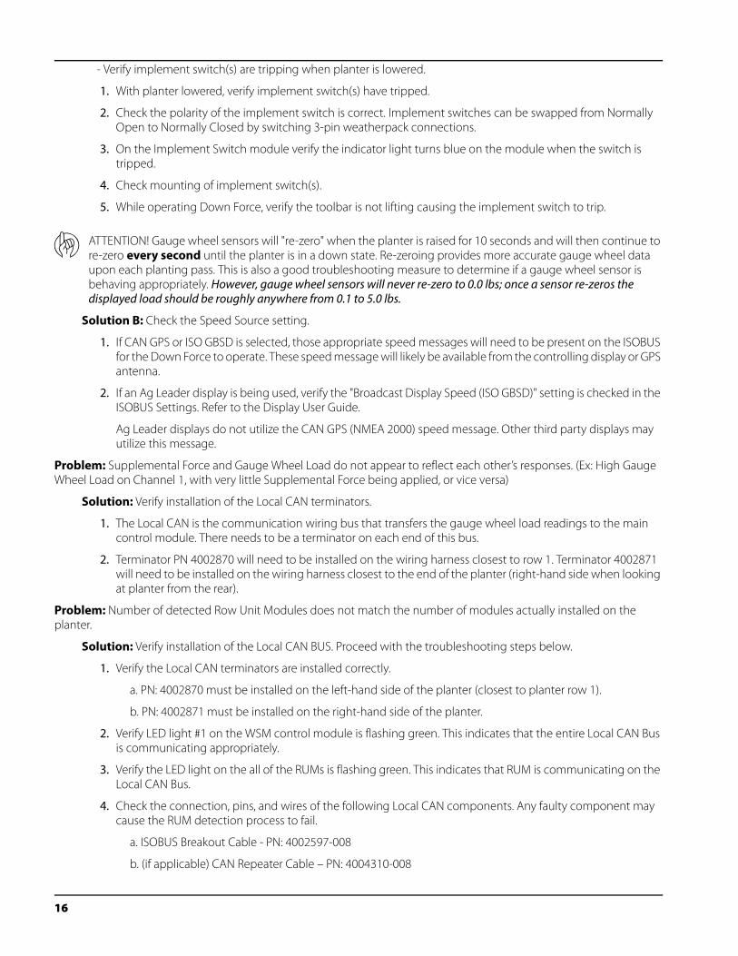
- Verify implement switch(s) are tripping when planter is lowered.
1. With planter lowered, verify implement switch(s) have tripped.
2. Check the polarity of the implement switch is correct. Implement switches can be swapped from Normally Open to Normally Closed by switching 3-pin weatherpack connections.
3. On the Implement Switch module verify the indicator light turns blue on the module when the switch is tripped.
4. Check mounting of implement switch(s).
5. While operating Down Force, verify the toolbar is not lifting causing the implement switch to trip.
μ ATTENTION! Gauge wheel sensors will "re-zero" when the planter is raised for 10 seconds and will then continue to re-zero every second until the planter is in a down state. Re-zeroing provides more accurate gauge wheel data upon each planting pass. This is also a good troubleshooting measure to determine if a gauge wheel sensor is behaving appropriately. However, gauge wheel sensors will never re-zero to 0.0 lbs; once a sensor re-zeros the displayed load should be roughly anywhere from 0.1 to 5.0 lbs.
Solution B: Check the Speed Source setting.
1. If CAN GPS or ISO GBSD is selected, those appropriate speed messages will need to be present on the ISOBUS for the Down Force to operate. These speed message will likely be available from the controlling display or GPS antenna.
2. If an Ag Leader display is being used, verify the "Broadcast Display Speed (ISO GBSD)" setting is checked in the ISOBUS Settings. Refer to the Display User Guide.
Ag Leader displays do not utilize the CAN GPS (NMEA 2000) speed message. Other third party displays may utilize this message.
Problem: Supplemental Force and Gauge Wheel Load do not appear to reflect each other’s responses. (Ex: High Gauge Wheel Load on Channel 1, with very little Supplemental Force being applied, or vice versa)
Solution: Verify installation of the Local CAN terminators.
1. The Local CAN is the communication wiring bus that transfers the gauge wheel load readings to the main control module. There needs to be a terminator on each end of this bus.
2. Terminator PN 4002870 will need to be installed on the wiring harness closest to row 1. Terminator 4002871 will need to be installed on the wiring harness closest to the end of the planter (right-hand side when looking at planter from the rear).
Problem: Number of detected Row Unit Modules does not match the number of modules actually installed on the planter.
Solution: Verify installation of the Local CAN BUS. Proceed with the troubleshooting steps below.
1. Verify the Local CAN terminators are installed correctly.
a. PN: 4002870 must be installed on the left-hand side of the planter (closest to planter row 1).
b. PN: 4002871 must be installed on the right-hand side of the planter.
2. Verify LED light #1 on the WSM control module is flashing green. This indicates that the entire Local CAN Bus is communicating appropriately.
3. Verify the LED light on the all of the RUMs is flashing green. This indicates that RUM is communicating on the Local CAN Bus.
4. Check the connection, pins, and wires of the following Local CAN components. Any faulty component may cause the RUM detection process to fail.
a. ISOBUS Breakout Cable - PN: 4002597-008
b. (if applicable) CAN Repeater Cable – PN: 4004310-008
16
ISOBUS Hydraulic Down Force
c. Local CAN Bus Extension Cable – PN: 4002807-X
d. Row Unit CAN Stub Cable – PN: 4004311-4
5. To narrow down a faulty component, begin with a fewer amount of RUMs on the Local Bus. The Local CAN terminators may be moved inward and connected to any Local CAN stub or extension cable. (i.e. Terminate after the middle 2 RUMs; therefore only 2 RUMs will now detect when the WSM control module is powered on) Cycle power each time the terminators are moved.
a. Proceed to move the terminators inward or back-out depending on the results of the new detection.
6. Verify that the WSM control module firmware is up to date.
7. A module Reset may be required if the WSM control module keeps booting to Demo Mode or with the incorrect number of RUMs detected.
8. If schematics are available, check continuity and/or power on suspect components.
Implement Switch Adjustment ProblemsProblem A: Down Force is too high at the beginning of a pass after the planter has been raised.
This problem can be caused by the implement switch tripping too late when the planter is being raised. If a row with a gauge wheel sensor comes off the ground before the implement switch trips, there is the chance the sensor will register no gauge wheel load and the system will react to it and apply down force. Once the switch trips, this higher down force is now held. When the planter resumes, down force may be initially excessive until it can relieve pressure.
Solution: Adjust the implement switch mounting so that it trips sooner when raising the planter. This will allow the system to hold the appropriate amount of down force.
Problem B: Low gauge wheel load is witnessed on a row causing the system to apply Max down force; but after inspection of the seed trench, the problem row appears to be receiving adequate gauge wheel load.
This problem can be caused by the implement switch tripping too late when the planter is being lowered. If a row with a gauge wheel sensor makes contact with the ground before the implement switch trips, there is the chance the sensor will register a load. Since the implement switch has not tripped yet, the gauge wheel sensors are still continuously re-zeroing every second, after the initial 10 seconds. (Ex: 50 lbs of actual load may be displayed as 0 lbs). The down force system will detect the “lower gauge wheel load” and react to it by applying more down force until the sensor reaches an acceptable load.
Solution: Raise the planter to allow the sensors to re-zero with no load on the gauge wheels. Adjust the implement switch so that it trips sooner when lowering the planter. This will prevent the false gauge wheel load readings.
17 PN 2006027–ENG Rev. H
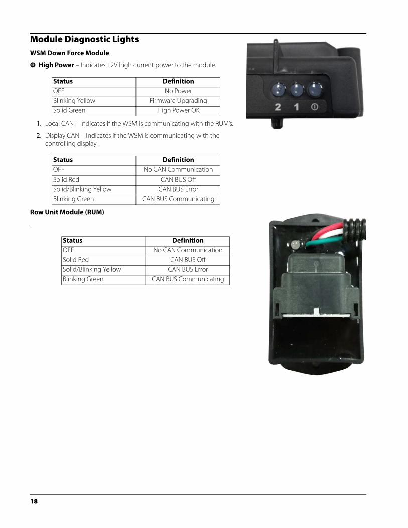
Module Diagnostic LightsWSM Down Force Module
Φ High Power – Indicates 12V high current power to the module.
1. Local CAN – Indicates if the WSM is communicating with the RUM’s.
2. Display CAN – Indicates if the WSM is communicating with the controlling display.
Row Unit Module (RUM)
.
Status DefinitionOFF No PowerBlinking Yellow Firmware UpgradingSolid Green High Power OK
Status DefinitionOFF No CAN CommunicationSolid Red CAN BUS OffSolid/Blinking Yellow CAN BUS ErrorBlinking Green CAN BUS Communicating
Status DefinitionOFF No CAN CommunicationSolid Red CAN BUS OffSolid/Blinking Yellow CAN BUS ErrorBlinking Green CAN BUS Communicating
18
ISOBUS Hydraulic Down Force
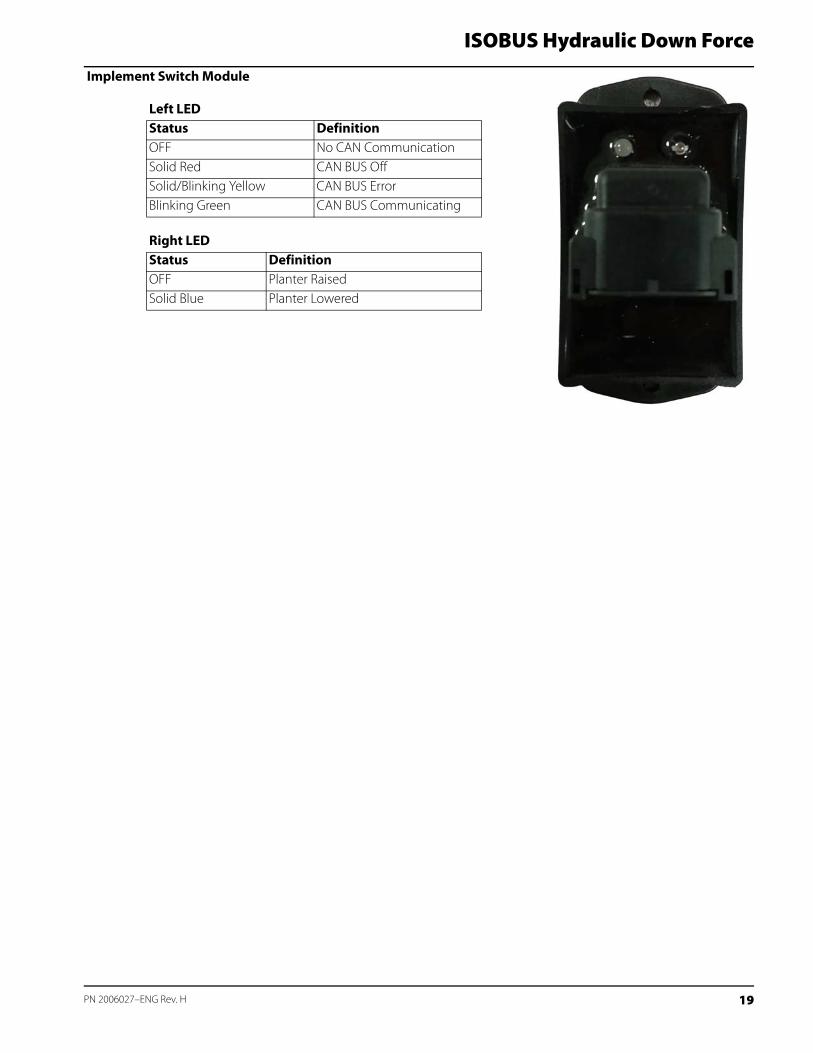
Implement Switch Module
Left LEDStatus DefinitionOFF No CAN CommunicationSolid Red CAN BUS OffSolid/Blinking Yellow CAN BUS ErrorBlinking Green CAN BUS Communicating
Right LEDStatus DefinitionOFF Planter RaisedSolid Blue Planter Lowered
19 PN 2006027–ENG Rev. H

20