Embed Size (px)
Citation preview
1
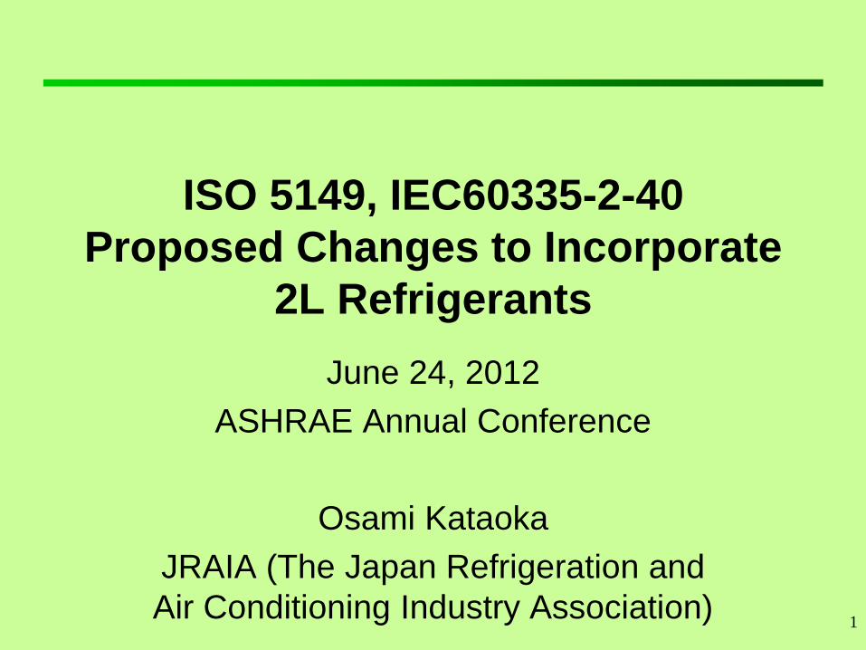
ISO 5149, IEC60335-2-40
Proposed Changes to Incorporate
2L Refrigerants
June 24, 2012
ASHRAE Annual Conference
Osami Kataoka
JRAIA (The Japan Refrigeration and
Air Conditioning Industry Association)
2
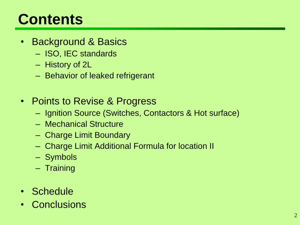
Contents
• Background & Basics – ISO, IEC standards
– History of 2L
– Behavior of leaked refrigerant
• Points to Revise & Progress – Ignition Source (Switches, Contactors & Hot surface)
– Mechanical Structure
– Charge Limit Boundary
– Charge Limit Additional Formula for location II
– Symbols
– Training
• Schedule
• Conclusions
3
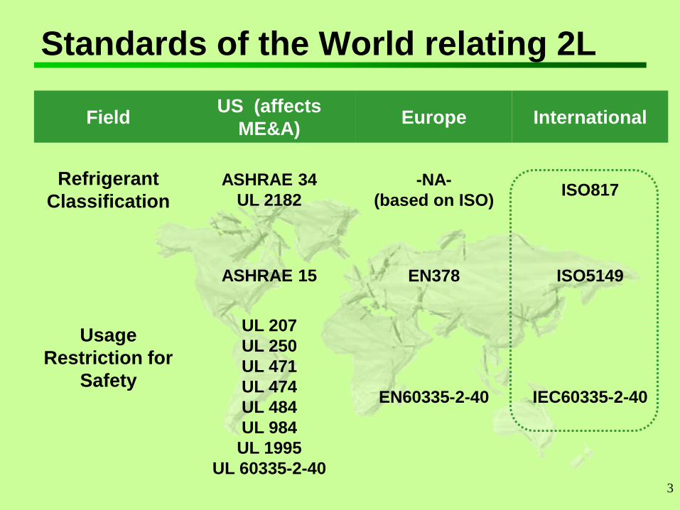
Standards of the World relating 2L
Field US (affects
ME&A) Europe International
Refrigerant
Classification
ASHRAE 34
UL 2182
-NA-
(based on ISO) ISO817
Usage
Restriction for
Safety
ASHRAE 15 EN378 ISO5149
UL 207
UL 250
UL 471
UL 474
UL 484
UL 984
UL 1995
UL 60335-2-40
EN60335-2-40 IEC60335-2-40
4
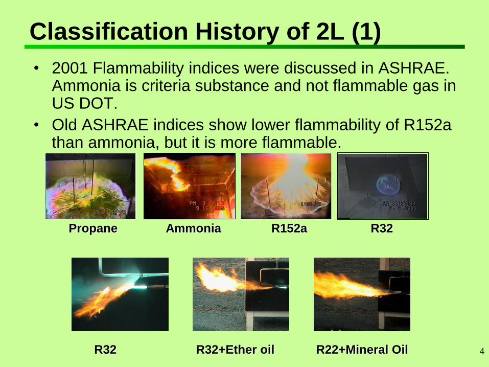
Classification History of 2L (1)
• 2001 Flammability indices were discussed in ASHRAE. Ammonia is criteria substance and not flammable gas in US DOT.
• Old ASHRAE indices show lower flammability of R152a than ammonia, but it is more flammable.
Propane R152a Ammonia R32
R32 R22+Mineral Oil R32+Ether oil
5
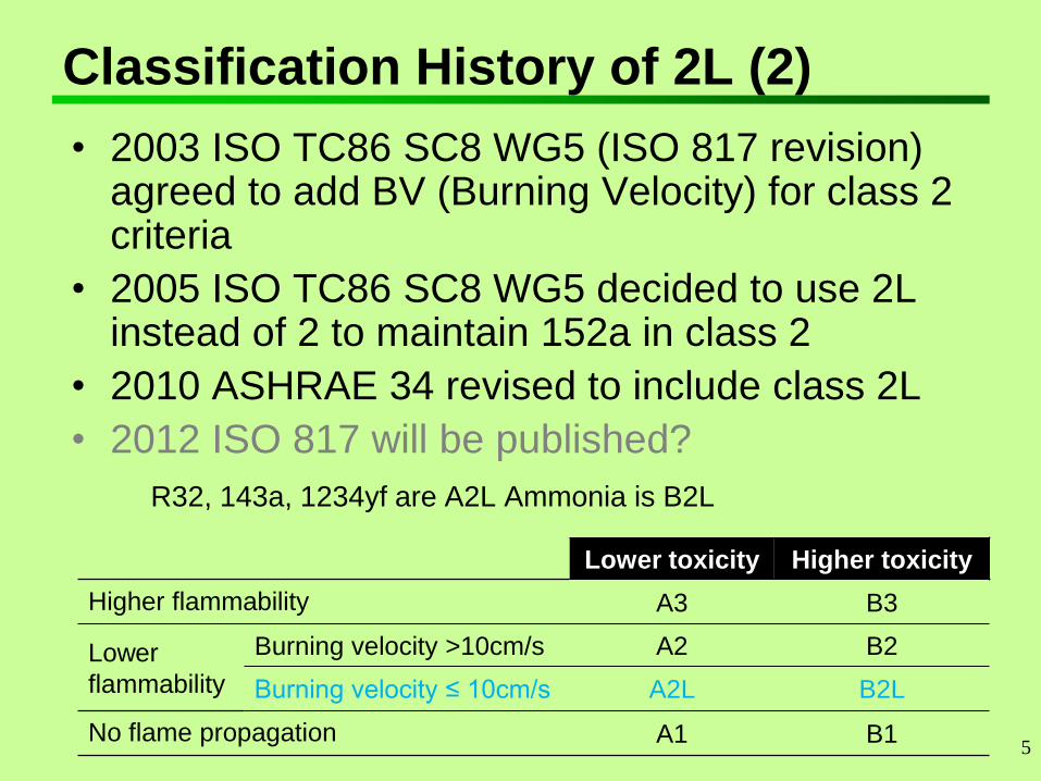
Classification History of 2L (2)
• 2003 ISO TC86 SC8 WG5 (ISO 817 revision) agreed to add BV (Burning Velocity) for class 2 criteria
• 2005 ISO TC86 SC8 WG5 decided to use 2L instead of 2 to maintain 152a in class 2
• 2010 ASHRAE 34 revised to include class 2L
• 2012 ISO 817 will be published?
R32, 143a, 1234yf are A2L Ammonia is B2L
Lower toxicity Higher toxicity
Higher flammability A3 B3
Lower
flammability
Burning velocity >10cm/s A2 B2
Burning velocity ≤ 10cm/s A2L B2L
No flame propagation A1 B1
6
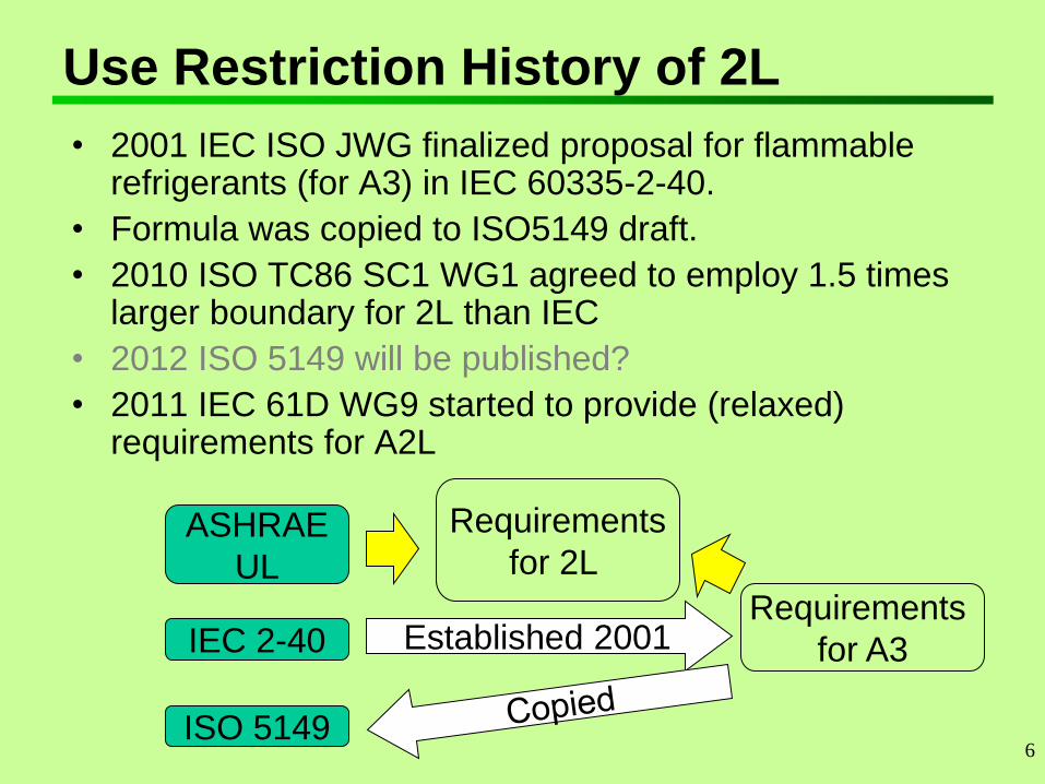
Use Restriction History of 2L
• 2001 IEC ISO JWG finalized proposal for flammable refrigerants (for A3) in IEC 60335-2-40.
• Formula was copied to ISO5149 draft.
• 2010 ISO TC86 SC1 WG1 agreed to employ 1.5 times larger boundary for 2L than IEC
• 2012 ISO 5149 will be published?
• 2011 IEC 61D WG9 started to provide (relaxed) requirements for A2L
ASHRAE
UL
IEC 2-40
Requirements
for 2L
Requirements
for A3 Established 2001
ISO 5149
7
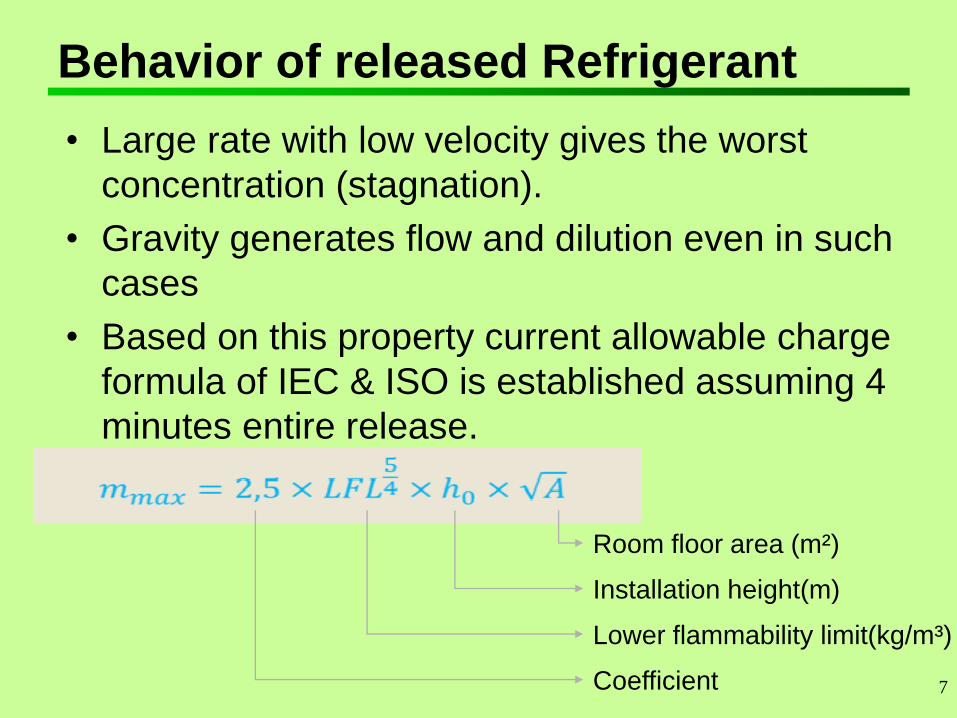
Behavior of released Refrigerant
• Large rate with low velocity gives the worst
concentration (stagnation).
• Gravity generates flow and dilution even in such
cases
• Based on this property current allowable charge
formula of IEC & ISO is established assuming 4
minutes entire release.
Room floor area (m²)
Installation height(m)
Lower flammability limit(kg/m³)
Coefficient
8
Points to Revise and Progress
1. Ignition Source (Switches, Contactors & Hot
surfaces)
2. Charge Limit Boundary
3. Charge Limit Additional Formula
4. Mechanical Structure
5. Symbols and Marking
6. Training
9
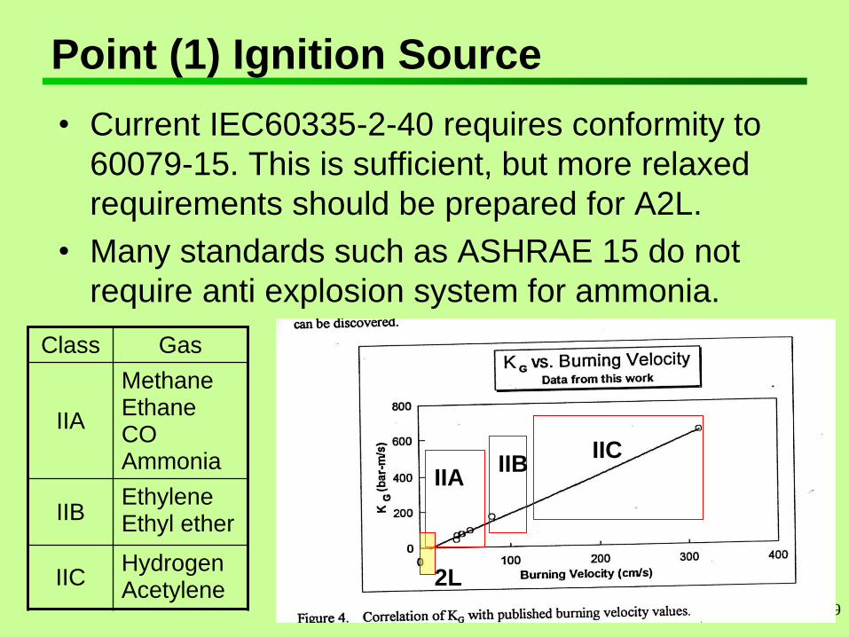
Point (1) Ignition Source
• Current IEC60335-2-40 requires conformity to
60079-15. This is sufficient, but more relaxed
requirements should be prepared for A2L.
• Many standards such as ASHRAE 15 do not
require anti explosion system for ammonia.
Class Gas
IIA
Methane Ethane CO Ammonia
IIB Ethylene Ethyl ether
IIC Hydrogen Acetylene
IIC IIB
IIA
2L
10
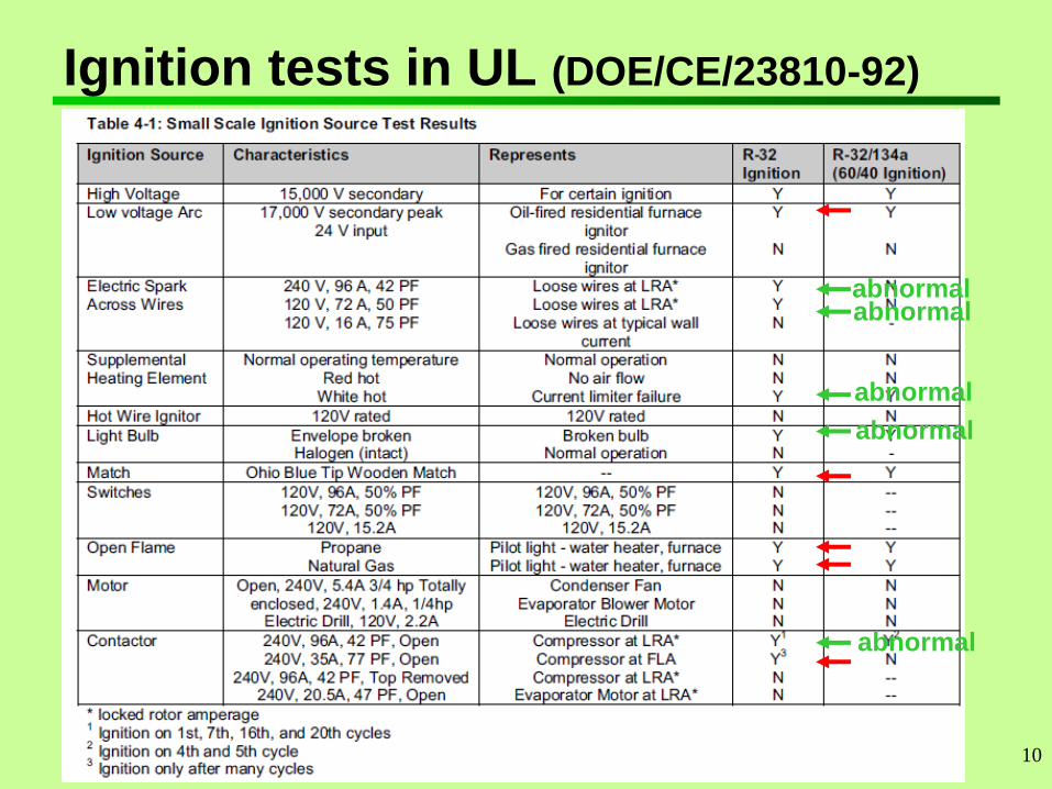
Ignition tests in UL (DOE/CE/23810-92)
abnormal abnormal
abnormal
abnormal
abnormal
11
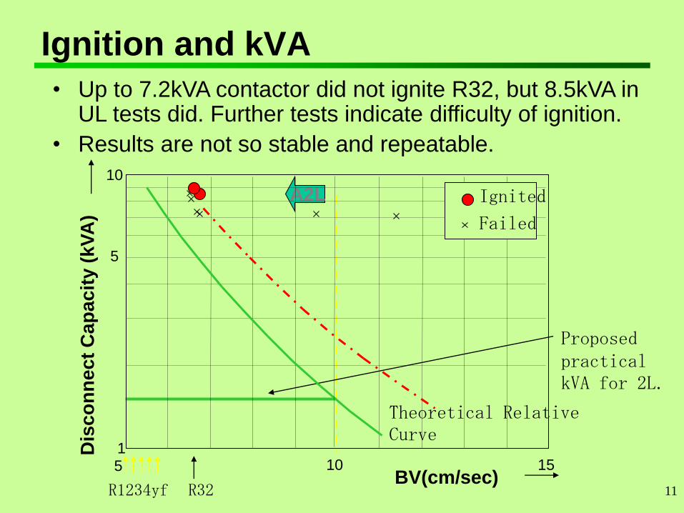
Ignition and kVA
• Up to 7.2kVA contactor did not ignite R32, but 8.5kVA in UL tests did. Further tests indicate difficulty of ignition.
• Results are not so stable and repeatable.
BV(cm/sec)
Dis
co
nn
ec
t C
ap
ac
ity (
kV
A)
A2L
R32 R1234yf
Theoretical Relative Curve
Proposed practical kVA for 2L.
1
10
5 10 15
5
Ignited
Failed
12
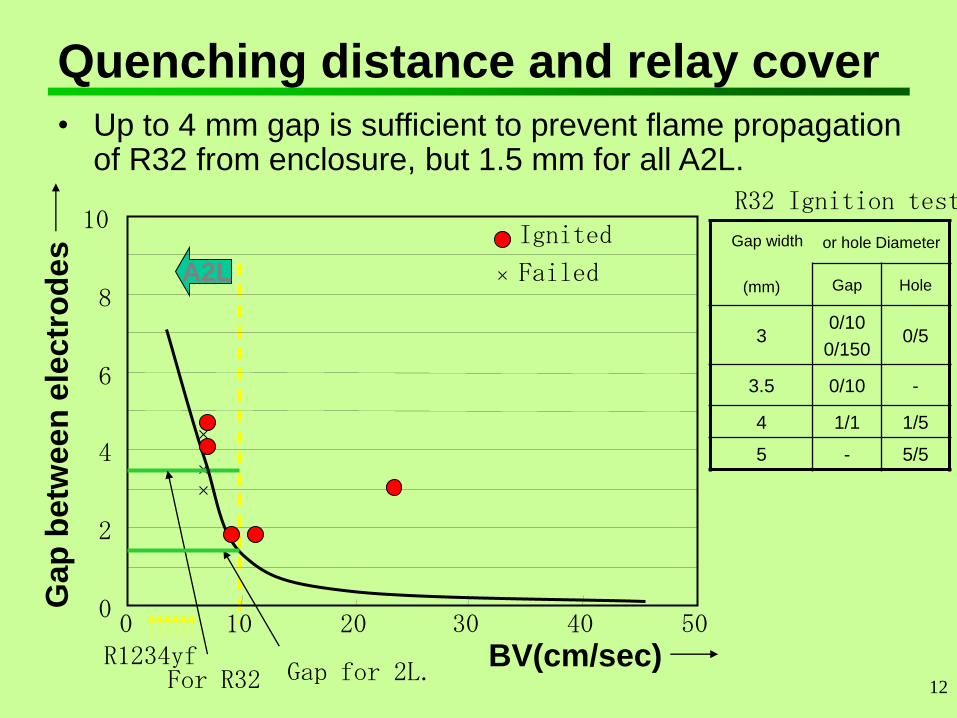
Quenching distance and relay cover
• Up to 4 mm gap is sufficient to prevent flame propagation of R32 from enclosure, but 1.5 mm for all A2L.
BV(cm/sec)
Ga
p b
etw
een
ele
ctr
od
es
A2L
0
2
4
6
8
10
0 10 20 30 40 50
For R32 R1234yf
Ignited
Failed
Gap for 2L.
Gap width
(mm)
or hole Diameter
Gap Hole
3 0/10
0/150 0/5
3.5 0/10 -
4 1/1 1/5
5 - 5/5
R32 Ignition test
13
Hot surface
• IEC 60335-2-40 requires
AIT –100 °K> hot surface temperature
AIT: Auto Ignition Temperature
• 700 °C is proposed for A2.
• AIT test is not for hot surface limit. Much higher
temperature hot surface than AIT cannot ignite
even hydrocarbon.
• No objection, but confirming other data. Limiting
known substance only.
14
Point (2) Boundary of Formula
• Only very small flammable cloud is allowed for
A3. Theoretical relative calculation gives around
5 times larger amount of 2L could generate the
same pressure rise.
• The same level of risk to HC equipment appears
too high for real public use.
• Proposal is to increase 2 times for formula use
limit and maximum charge with measures, but
1.5 times for no restriction amount.
15
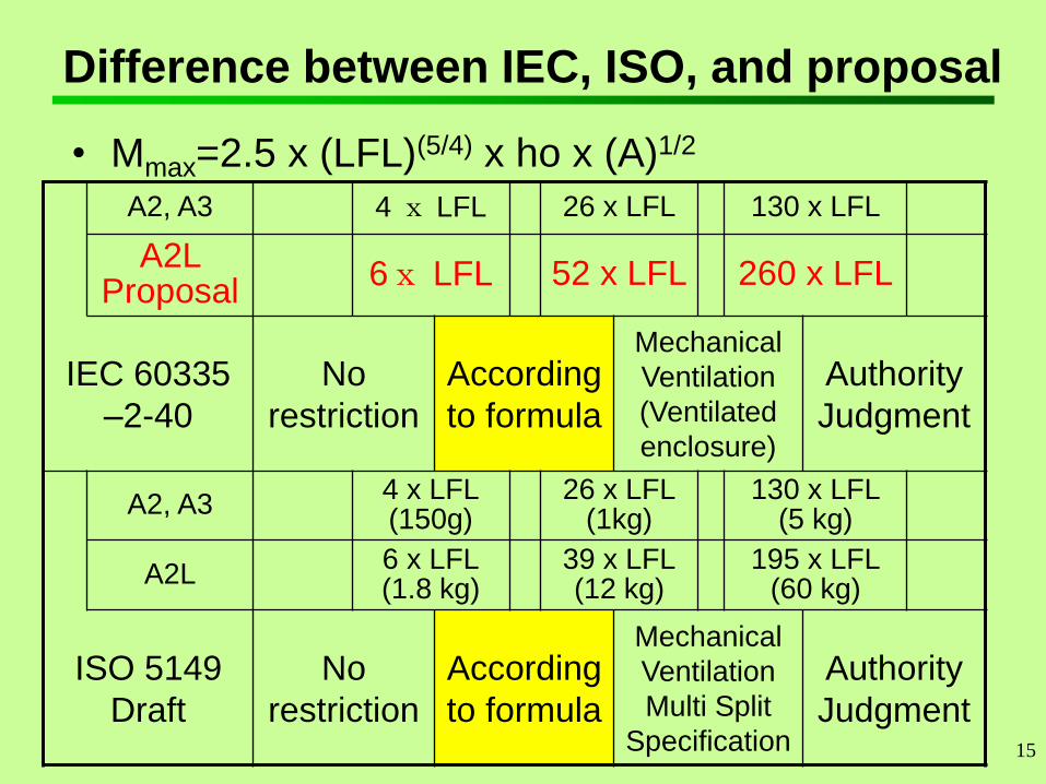
Difference between IEC, ISO, and proposal
• Mmax=2.5 x (LFL)(5/4) x ho x (A)1/2
A2, A3 4 x LFL 26 x LFL 130 x LFL
A2L Proposal
6x LFL 52 x LFL 260 x LFL
IEC 60335
–2-40
No
restriction
According
to formula
Mechanical
Ventilation
(Ventilated
enclosure)
Authority
Judgment
A2, A3 4 x LFL (150g)
26 x LFL (1kg)
130 x LFL (5 kg)
A2L 6 x LFL (1.8 kg)
39 x LFL (12 kg)
195 x LFL (60 kg)
ISO 5149
Draft
No
restriction
According
to formula
Mechanical
Ventilation
Multi Split
Specification
Authority
Judgment
16
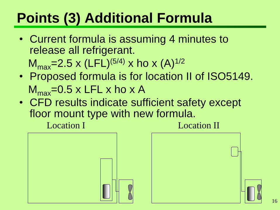
Points (3) Additional Formula
• Current formula is assuming 4 minutes to release all refrigerant.
Mmax=2.5 x (LFL)(5/4) x ho x (A)1/2
• Proposed formula is for location II of ISO5149.
Mmax=0.5 x LFL x ho x A
• CFD results indicate sufficient safety except floor mount type with new formula.
Location I Location II
17
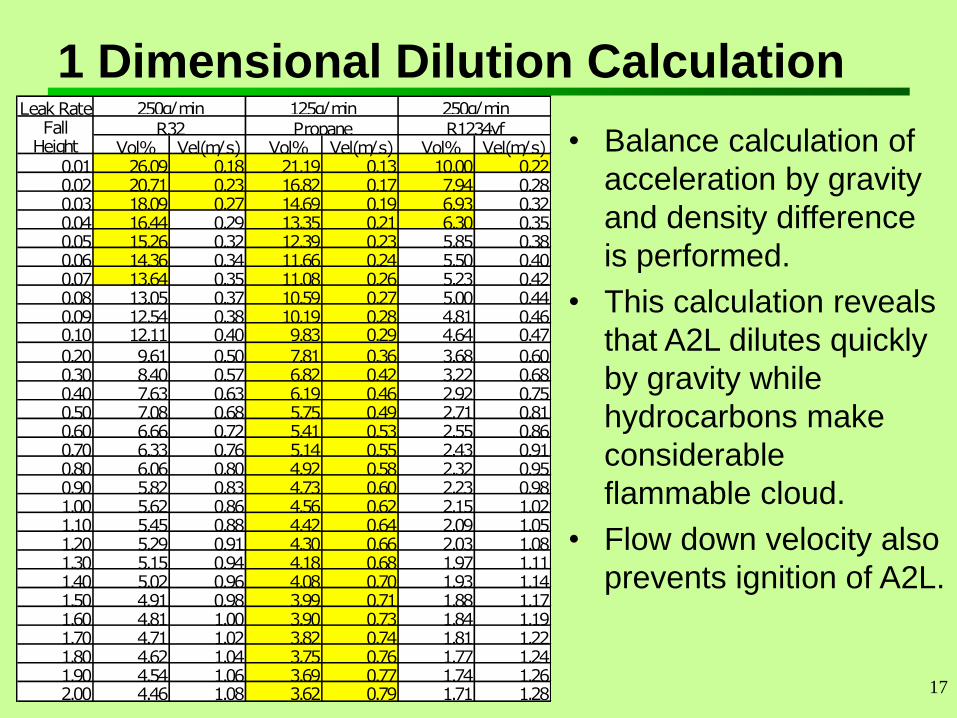
1 Dimensional Dilution Calculation Leak Rate
Vol% Vel(m/s) Vol% Vel(m/s) Vol% Vel(m/s)0.01 26.09 0.18 21.19 0.13 10.00 0.220.02 20.71 0.23 16.82 0.17 7.94 0.280.03 18.09 0.27 14.69 0.19 6.93 0.320.04 16.44 0.29 13.35 0.21 6.30 0.350.05 15.26 0.32 12.39 0.23 5.85 0.380.06 14.36 0.34 11.66 0.24 5.50 0.400.07 13.64 0.35 11.08 0.26 5.23 0.420.08 13.05 0.37 10.59 0.27 5.00 0.440.09 12.54 0.38 10.19 0.28 4.81 0.460.10 12.11 0.40 9.83 0.29 4.64 0.470.20 9.61 0.50 7.81 0.36 3.68 0.600.30 8.40 0.57 6.82 0.42 3.22 0.680.40 7.63 0.63 6.19 0.46 2.92 0.750.50 7.08 0.68 5.75 0.49 2.71 0.810.60 6.66 0.72 5.41 0.53 2.55 0.860.70 6.33 0.76 5.14 0.55 2.43 0.910.80 6.06 0.80 4.92 0.58 2.32 0.950.90 5.82 0.83 4.73 0.60 2.23 0.981.00 5.62 0.86 4.56 0.62 2.15 1.021.10 5.45 0.88 4.42 0.64 2.09 1.051.20 5.29 0.91 4.30 0.66 2.03 1.081.30 5.15 0.94 4.18 0.68 1.97 1.111.40 5.02 0.96 4.08 0.70 1.93 1.141.50 4.91 0.98 3.99 0.71 1.88 1.171.60 4.81 1.00 3.90 0.73 1.84 1.191.70 4.71 1.02 3.82 0.74 1.81 1.221.80 4.62 1.04 3.75 0.76 1.77 1.241.90 4.54 1.06 3.69 0.77 1.74 1.262.00 4.46 1.08 3.62 0.79 1.71 1.28
250g/min 125g/min 250g/minFall
HeightR32 Propane R1234yf
• Balance calculation of
acceleration by gravity
and density difference
is performed.
• This calculation reveals
that A2L dilutes quickly
by gravity while
hydrocarbons make
considerable
flammable cloud.
• Flow down velocity also
prevents ignition of A2L.
18
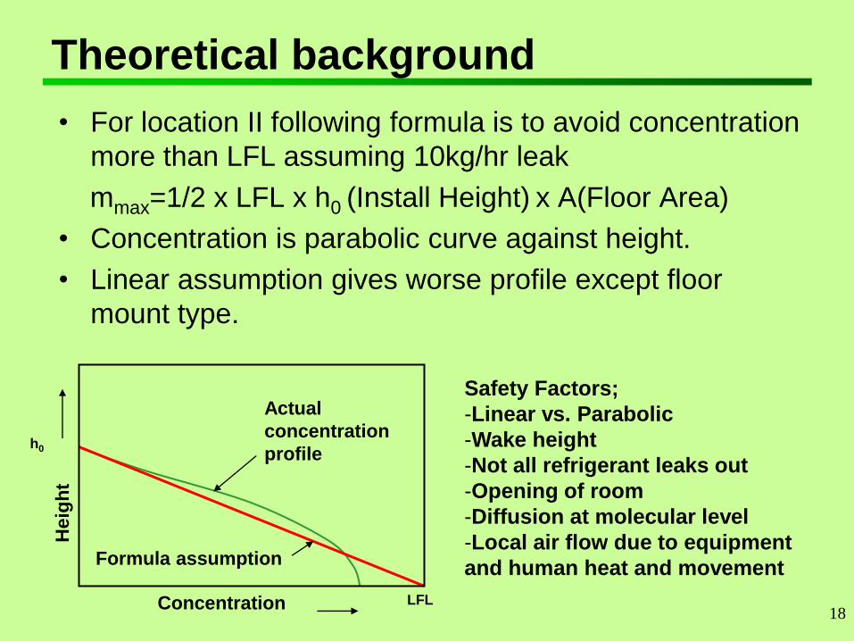
Theoretical background
• For location II following formula is to avoid concentration
more than LFL assuming 10kg/hr leak
mmax=1/2 x LFL x h0 (Install Height) x A(Floor Area)
• Concentration is parabolic curve against height.
• Linear assumption gives worse profile except floor
mount type.
Concentration
Heig
ht
Formula assumption
Actual
concentration
profile
LFL
h0
Safety Factors;
-Linear vs. Parabolic
-Wake height
-Not all refrigerant leaks out
-Opening of room
-Diffusion at molecular level
-Local air flow due to equipment
and human heat and movement
19
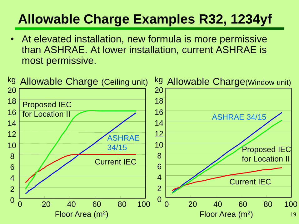
Allowable Charge Examples R32, 1234yf
• At elevated installation, new formula is more permissive than ASHRAE. At lower installation, current ASHRAE is most permissive.
Allowable Charge (Ceiling unit)
0
2
4
6
8
10
12
14
16
18
20
0 20 40 60 80 100
Floor Area (m2)
Allowable Charge(Window unit)
0
2
4
6
8
10
12
14
16
18
20
0 20 40 60 80 100
Floor Area (m2)
Current IEC
Proposed IEC
for Location II
ASHRAE 34/15
Current IEC
Proposed IEC
for Location II
ASHRAE
34/15
kg kg
20
Point (4) Mechanical Structure
• Detachable joints at indoor are not allowed in
current IEC for flammable refrigerants
• ISO5149 draft does not require permanent joints
for A2L
• IEC 61D WG7 agreed to remove this
requirement, but the proposal was accidentally
eliminated
• IEC 61D WG9 agreed to follow ISO5149 draft.
21
Point (5) Symbols & Marking
• Marking should be different from A3, but
marking standard is not clear.
• Transportation marking from GHS that requires
“extremely flammable gas: danger” marking and
flame symbol may be another problem.
Ammonia requires just “warning; flammable
gas” marking.
• The Label to require the minimum area does not
apply below 1.8 kg of A2L charge.
22
Point (6) Training
• Current text of Annex DD is for A3.
Understanding of A2L flammability is necessary,
but not easy to ignite A2L.
• Flammability risk of lubricant may be higher
than A2L refrigerant.
• LFL of A2L is higher than RCL of R22. Number
of people is more than ignition source of A2L.
That means much higher risk of R22 toxicity
than A2L flammability. Training for toxicity of
R22 was very limited, but accident was rare.
• Relaxed requirements are proposed.
23
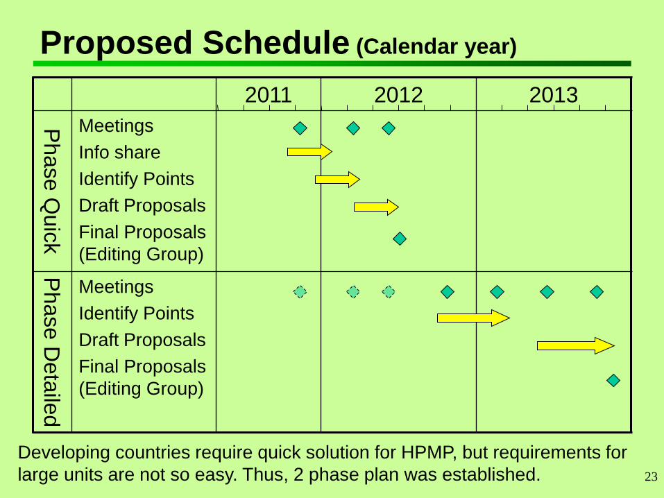
Proposed Schedule (Calendar year)
2011 2012 2013
Phase Q
uic
k
Meetings
Info share
Identify Points
Draft Proposals
Final Proposals
(Editing Group)
Phase D
eta
iled
Meetings
Identify Points
Draft Proposals
Final Proposals
(Editing Group)
Developing countries require quick solution for HPMP, but requirements for
large units are not so easy. Thus, 2 phase plan was established.
24
Conclusions
• IEC SC61D WG 9 is taking leading role to establish requirements for A2L in ISO/IEC (and EN) standards.
• Requirements for A2L are proposed and are being established in IEC SC 61D WG9 for smaller or simpler products quickly.
• Relaxation from A3 requirements appear reasonable, specifically for the following points.
(1) Ignition Source (Switches, Contactors & Hot surfaces)
(2) Charge Limit Boundary
(3) Charge Limit Additional Formula
(4) Mechanical Structure
(5) Symbols & Marking
(6) Training
• The standard IEC60335-2-40 will hopefully be revised according to the proposals of WG9 in one year.
• Further requirements will be developed for larger and more complex products in 2 years.
25
END
Thank you for your attention!


![Hungary [2l]](https://img.pdfslide.us/doc/110x75/5583e360d8b42aaa5a8b4cf4/hungary-2l.jpg)