Embed Size (px)
Citation preview
Reference numberISO 14644-4:2001(E)
© ISO 2001
INTERNATIONALSTANDARD
ISO14644-4
First edition2001-04-01
Cleanrooms and associated controlledenvironments —
Part 4:Design, construction and start-up
Salles propres et environnements maîtrisés apparentés —
Partie 4: Conception, construction et mise en fonctionnement
Copyright International Organization for Standardization Provided by IHS under license with ISO
Not for ResaleNo reproduction or networking permitted without license from IHS
--`,,`,-`-`,,`,,`,`,,`---
ISO 14644-4:2001(E)
PDF disclaimer
This PDF file may contain embedded typefaces. In accordance with Adobe's licensing policy, this file may be printed or viewed but shall notbe edited unless the typefaces which are embedded are licensed to and installed on the computer performing the editing. In downloading thisfile, parties accept therein the responsibility of not infringing Adobe's licensing policy. The ISO Central Secretariat accepts no liability in thisarea.
Adobe is a trademark of Adobe Systems Incorporated.
Details of the software products used to create this PDF file can be found in the General Info relative to the file; the PDF-creation parameterswere optimized for printing. Every care has been taken to ensure that the file is suitable for use by ISO member bodies. In the unlikely eventthat a problem relating to it is found, please inform the Central Secretariat at the address given below.
© ISO 2001
All rights reserved. Unless otherwise specified, no part of this publication may be reproduced or utilized in any form or by any means, electronicor mechanical, including photocopying and microfilm, without permission in writing from either ISO at the address below or ISO's member bodyin the country of the requester.
ISO copyright officeCase postale 56 � CH-1211 Geneva 20Tel. + 41 22 749 01 11Fax + 41 22 749 09 47E-mail [email protected] www.iso.ch
Printed in Switzerland
ii © ISO 2001 – All rights reservedCopyright International Organization for Standardization Provided by IHS under license with ISO
Not for ResaleNo reproduction or networking permitted without license from IHS
--`,,`,-`-`,,`,,`,`,,`---
ISO 14644-4:2001(E)
© ISO 2001 – All rights reserved iii
Contents
Foreword.....................................................................................................................................................................iv
Introduction .................................................................................................................................................................v
1 Scope ..............................................................................................................................................................1
2 Normative references ....................................................................................................................................1
3 Terms and definitions ...................................................................................................................................2
4 Requirements.................................................................................................................................................3
5 Planning and design......................................................................................................................................45.1 Planning procedure .......................................................................................................................................45.2 Design .............................................................................................................................................................5
6 Construction and start-up.............................................................................................................................5
7 Testing and approval.....................................................................................................................................67.1 General............................................................................................................................................................67.2 Construction approval ..................................................................................................................................67.3 Functional approval.......................................................................................................................................67.4 Operational approval.....................................................................................................................................6
8 Documentation...............................................................................................................................................68.1 General............................................................................................................................................................68.2 Record of an installation...............................................................................................................................68.3 Operational instructions ...............................................................................................................................68.4 Instructions for performance monitoring....................................................................................................78.5 Maintenance instructions .............................................................................................................................78.6 Maintenance record.......................................................................................................................................78.7 Record of operation and maintenance training..........................................................................................8
Annex A (informative) Control and segregation concepts......................................................................................9
Annex B (informative) Classification examples .....................................................................................................16
Annex C (informative) Approval of an installation.................................................................................................19
Annex D (informative) Layout of an installation.....................................................................................................23
Annex E (informative) Construction and materials................................................................................................27
Annex F (informative) Environmental control of cleanrooms ..............................................................................32
Annex G (informative) Control of air cleanliness...................................................................................................35
Annex H (informative) Additional specification of requirements to be agreed upon betweenpurchaser/user and designer/supplier ......................................................................................................37
Bibliography ..............................................................................................................................................................50
Copyright International Organization for Standardization Provided by IHS under license with ISO
Not for ResaleNo reproduction or networking permitted without license from IHS
--`,,`,-`-`,,`,,`,`,,`---
ISO 14644-4:2001(E)
iv © ISO 2001 – All rights reserved
Foreword
ISO (the International Organization for Standardization) is a worldwide federation of national standards bodies (ISOmember bodies). The work of preparing International Standards is normally carried out through ISO technicalcommittees. Each member body interested in a subject for which a technical committee has been established hasthe right to be represented on that committee. International organizations, governmental and non-governmental, inliaison with ISO, also take part in the work. ISO collaborates closely with the International ElectrotechnicalCommission (IEC) on all matters of electrotechnical standardization.
International Standards are drafted in accordance with the rules given in the ISO/IEC Directives, Part 3.
Draft International Standards adopted by the technical committees are circulated to the member bodies for voting.Publication as an International Standard requires approval by at least 75 % of the member bodies casting a vote.
Attention is drawn to the possibility that some of the elements of this part of ISO 14644 may be the subject ofpatent rights. ISO shall not be held responsible for identifying any or all such patent rights.
International Standard ISO 14644-4 was prepared by Technical Committee ISO/TC 209, Cleanrooms andassociated controlled environments.
ISO 14644 consists of the following parts, under the general title Cleanrooms and associated controlledenvironments:
� Part 1: Classification of air cleanliness
� Part 2: Specifications for testing and monitoring to prove continued compliance with ISO 14644-1
� Part 3: Metrology and test methods
� Part 4: Design, construction and start-up
� Part 5: Operations
� Part 6: Vocabulary
� Part 7: Separative enclosures (clean air hoods, glove boxes, isolators, mini-environments)
Users should note that the titles listed for parts 3 and 5 to 7 are working titles at the time of the release of part 4. Inthe event that one or more of these parts are deleted from the work programme, the remaining parts may berenumbered.
Annexes A to H of this part of ISO 14644 are for information only.
Copyright International Organization for Standardization Provided by IHS under license with ISO
Not for ResaleNo reproduction or networking permitted without license from IHS
--`,,`,-`-`,,`,,`,`,,`---
ISO 14644-4:2001(E)
© ISO 2001 – All rights reserved v
Introduction
Cleanrooms and associated controlled environments provide for the control of airborne particulate contamination tolevels appropriate for accomplishing contamination-sensitive activities. Products and processes that benefit fromthe control of airborne contamination include those in such industries as aerospace, microelectronics,pharmaceuticals, medical devices and healthcare.
This part of ISO 14644 specifies the requirements for the design and construction of cleanroom facilities. It isintended for use by purchasers, suppliers and designers of cleanroom installations and provides a check list ofimportant parameters of performance. Construction guidance is provided, including requirements for start-up andqualification. Basic elements of design and construction needed to ensure continued satisfactory operation areidentified through the consideration of relevant aspects of operation and maintenance.
This part of ISO 14644 is one of a series of standards concerned with cleanrooms and associated subjects. Manyfactors besides design, construction and start-up should be considered in the operation and control of cleanroomsand other controlled environments. These are covered in some detail in other International Standards prepared byISO/TC 209.
Copyright International Organization for Standardization Provided by IHS under license with ISO
Not for ResaleNo reproduction or networking permitted without license from IHS
--`,,`,-`-`,,`,,`,`,,`---

Copyright International Organization for Standardization Provided by IHS under license with ISO
Not for ResaleNo reproduction or networking permitted without license from IHS
--`,,`,-`-`,,`,,`,`,,`---
INTERNATIONAL STANDARD ISO 14644-4:2001(E)
© ISO 2001 – All rights reserved 1
Cleanrooms and associated controlled environments
Part 4:Design, construction and start-up
1 Scope
This part of ISO 14644 specifies requirements for the design and construction of cleanroom installations but doesnot prescribe specific technological or contractual means to meet these requirements. It is intended for use bypurchasers, suppliers and designers of cleanroom installations and provides a checklist of important parameters ofperformance. Construction guidance is provided, including requirements for start-up and qualification. Basicelements of design and construction needed to ensure continued satisfactory operation are identified through theconsideration of relevant aspects of operation and maintenance.
NOTE Further guidance in respect of the above requirements is given in annexes A to H. Other parts of ISO 14644 mayprovide complementary information.
Application of this part of ISO 14644 is restricted in the following:
� user requirements are represented by purchaser or specifier;
� specific processes to be accommodated in the cleanroom installation are not specified;
� fire and safety regulations are not considered specifically; the appropriate national and local requirementsshould be respected;
� process media and utility services are only considered with respect to their routing between and in the differentzones of cleanliness;
� regarding initial operation and maintenance, only cleanroom construction-specific requirements areconsidered.
2 Normative references
The following normative documents contain provisions which, through reference in this text, constitute provisions ofthis part of ISO 14644. For dated references, subsequent amendments to, or revisions of, any of these publicationsdo not apply. However, parties to agreements based on this part of ISO 14644 are encouraged to investigate thepossibility of applying the most recent editions of the normative documents indicated below. For undatedreferences, the latest edition of the normative document referred to applies. Members of ISO and IEC maintainregisters of currently valid International Standards.
ISO 14644-1:1999, Cleanrooms and associated controlled environments — Part 1: Classification of air cleanliness.
ISO 14644-2:2000, Cleanrooms and associated controlled environments — Part 2: Specifications for testing andmonitoring to prove continued compliance with ISO 14644-1.
Copyright International Organization for Standardization Provided by IHS under license with ISO
Not for ResaleNo reproduction or networking permitted without license from IHS
--`,,`,-`-`,,`,,`,`,,`---
ISO 14644-4:2001(E)
2 © ISO 2001 – All rights reserved
ISO 14644-3:— 1�, Cleanrooms and associated controlled environments — Part 3: Metrology and test methods.
ISO 14698-1:— 1), Cleanrooms and associated controlled environments — Biocontamination control —Part 1: General principles
ISO 14698-2:— 1), Cleanrooms and associated controlled environments — Biocontamination control —Part 2: Evaluation and interpretation of biocontamination data.
ISO 14698-3:— 1), Cleanrooms and associated controlled environements — Biocontamination control —Part 3: Measurement of the efficiency of processes of cleaning and/or disinfection of inert surfaces bearingbiocontaminated wet soiling or biofilms.
3 Terms and definitions
For the purposes of this part of ISO 14644, the terms and definitions given in ISO 14644-1 and the following apply.
3.1changing roomroom where people using a cleanroom may change into, or out of, cleanroom apparel
3.2clean air devicestand-alone equipment for treating and distributing clean air to achieve defined environmental conditions
3.3cleanlinesscondition of a product, surface, device, gas, fluid, etc. with a defined level of contamination
NOTE Contamination can be particulate, non-particulate, biological, molecular or of other consistency.
3.4commissioningplanned and documented series of inspections, adjustments and tests carried out systematically to set theinstallation into correct technical operation as specified
3.5contaminantany particulate, molecular, non-particulate and biological entity that can adversely affect the product or process
3.6non-unidirectional airflowair distribution where the supply air entering the clean zone mixes with the internal air by means of induction
3.7particleminute piece of matter with defined physical boundaries
NOTE For classification purposes refer to ISO 14644-1.
3.8pre-filterair filter fitted upstream of another filter to reduce the challenge on that filter
1� To be published.
Copyright International Organization for Standardization Provided by IHS under license with ISO
Not for ResaleNo reproduction or networking permitted without license from IHS
--`,,`,-`-`,,`,,`,`,,`---
ISO 14644-4:2001(E)
© ISO 2001 – All rights reserved 3
3.9process corelocation at which the process and the interaction between the environment and the process occurs
3.10start-upact of preparing and bringing an installation into active service, including all systems
EXAMPLE Systems may include procedures, training requirements, infrastructure, support services, statutory under-takings requirements.
3.11unidirectional airflowcontrolled airflow through the entire cross-section of a clean zone with a steady velocity and approximately parallelstreamlines
NOTE This type of airflow results in a directed transport of particles from the clean zone.
4 Requirements
4.1 The parameters listed in 4.2 to 4.18 shall be defined and agreed between purchaser and supplier:
NOTE In the requirements stated below, references are made to annexes A to H which are for information only.
4.2 The number, edition and date of publication of this part of ISO 14644 shall be given.
4.3 The role of other relevant parties to the project (e.g. consultants, designers, regulatory authorities, serviceorganizations) shall be established (see examples in annex C).
4.4 The general purpose for which the cleanroom is to be used, the operations to be carried out therein and anyconstraint imposed by the operating requirements (see examples in annexes A, B and D).
4.5 The required airborne particulate cleanliness class or demands for cleanliness in accordance with therelevant International Standard (ISO 14644-1, ISO 14698-1, ISO 14698-2 and ISO 14698-3) (see examples inannex B).
4.6 The critical environmental parameters, including their specified set points, alert and action levels to bemeasured to ensure compliance, together with the measurement methods to be used, including calibration(ISO 14644-2 and ISO 14644-3) (see examples in annex F).
4.7 The contamination control concept, including installation, operating and performance criteria, to be used toachieve the required cleanliness level (see examples in annex A).
4.8 The methods of measurement, control, monitoring and documentation required to meet the parametersagreed (see examples in annexes C and F).
4.9 The entry or exit of equipment, apparatus, supplies and personnel required to support the installation (seeexamples in annex D).
4.10 The specified occupancy states selected from "as-built", "at-rest" and "operational" under which the requiredparameters shall be achieved and maintained including variations with time, and the methods of control (seeexamples in annex C).
4.11 The layout and configuration of the installation (see examples in annex D).
4.12 Critical dimensions and mass restrictions, including those related to available space (see examples inannex D).
Copyright International Organization for Standardization Provided by IHS under license with ISO
Not for ResaleNo reproduction or networking permitted without license from IHS
--`,,`,-`-`,,`,,`,`,,`---
ISO 14644-4:2001(E)
4 © ISO 2001 – All rights reserved
4.13 The process and product requirements that affect the installation (see examples in annexes B and G).
4.14 The process equipment list with utility requirements (see examples in annexes D, E and H).
4.15 The maintenance requirements of the installation (see examples in annexes D and E).
4.16 The assignment of tasks for the preparation, approval, execution, supervision, documentation, statement ofcriteria, basis of design, detailed design, construction, testing, commissioning and qualification (including theperformance and witnessing) of tests (see examples in annexes E and G).
4.17 The identification and evaluation of external environmental influences (see examples in annex H).
4.18 Additional information required by the particular application (see examples in annex H).
5 Planning and design
5.1 Planning procedure
5.1.1 A project plan shall be developed, in consultation with the user and all other involved parties, to define therequirements of the products, the processes and the scope of the installation.
5.1.2 In order to determine the needs of an installation, a process equipment list shall be compiled, and shallinclude the critical requirements for each piece of process equipment.
5.1.3 Diversity factors shall be defined, considering peak and average demand for each utility and environmentalcontrol system.
NOTE A system may include multiple subsystems which require individual diversity-factor determination.
5.1.4 A contamination control concept shall be developed for each zone of an installation (see examples inannex A).
5.1.5 The specifications as defined in clause 4 shall be reviewed and refined based on financial and timescalerequirements.
5.1.6 The project plan shall include the following elements:
a) design documentation with support calculations;
b) cost evaluation;
c) timescale evaluation;
d) an outline of anticipated project complications;
e) design options with records of advantages and disadvantages and any recommendations;
f) a review of maintenance requirements of the installation;
g) a review of the degree of flexibility to be included in the installation;
h) a review of the stand-by capacities to be included in the installation;
i) a review of the constructability of the design of the installation;
j) a quality plan.
Copyright International Organization for Standardization Provided by IHS under license with ISO
Not for ResaleNo reproduction or networking permitted without license from IHS
--`,,`,-`-`,,`,,`,`,,`---
ISO 14644-4:2001(E)
© ISO 2001 – All rights reserved 5
The use of a quality system, such as the ISO 9000 family of international standards (e.g. ISO 9000 andISO 9001), should be considered, in conjunction with industry-specific quality assurance strategies.
5.1.7 The completed project plan shall be reviewed and agreed upon between purchaser and supplier.
5.2 Design
5.2.1 The design shall accommodate all of the relevant product and process requirements in conjunction with theselected contamination control concept (see examples in annex A).
5.2.2 The purchaser and supplier shall formally accept the design in accordance with predetermined acceptancecriteria.
5.2.3 The design shall conform to an agreed list of requirements, such as building, environmental and safetyregulations, good manufacturing practice guidelines (e.g. ISO 14001 and ISO 14004).
The design should be reviewed at periodic stages of development, including final completion, to ensure compliancewith the specifications and the acceptance criteria.
6 Construction and start-up
6.1 Construction of an installation shall comply with the drawings and specifications.
6.2 Any changes required during the course of construction shall be checked for acceptance, approved anddocumented prior to implementation of the change in accordance with a change control procedure.
6.3 Construction work, whether performed at a manufacturing location or in situ, shall observe the specificcontamination control requirements of the quality plan.
6.4 A clean construction protocol and cleaning procedures shall be developed as part of the quality plan andenforced to achieve the specified contamination control requirements. Security and access control is essential tomaintain the clean construction protocol.
6.5 The cleaning methods and methods to determine and approve the achieved cleanliness shall be defined anddocumented in the quality plan.
6.6 The cleaning of the air systems shall be specified and shall be carried out at assembly, before initialoperation and whenever rebuilding work, repair work and maintenance work are performed.
6.7 In the case of start-up of new installations or re-starting existing installations after repair or modification, finalcleaning of the cleanroom is necessary and provisions shall be made for the removal of adherent, imported orreleased contamination.
6.8 Before commencing any operational activities, the complete and satisfactory function of the installation shallbe determined by tests carried out in accordance with clause 7.
NOTE In the case of packaged units, such as clean air devices, a manufacturer's certificate of compliance with therequirements of this part of ISO 14644 may be sufficient, provided that the supplier is qualified (i.e. knowledgeable of orcompetent in cleanroom requirements) and the risk of damage during transport, storage and installation can be controlledadequately.
6.9 During acceptance testing, commissioning and initial operation, the personnel in charge of the installationshall be trained. Testing, approval of the installation and training shall include all relevant practices for propercleanroom operation, maintenance and in-process control. The responsibility for providing training shall be defined.
When training is carried out, all relevant persons such as operators, maintenance and service personnel should beincluded.
Copyright International Organization for Standardization Provided by IHS under license with ISO
Not for ResaleNo reproduction or networking permitted without license from IHS
--`,,`,-`-`,,`,,`,`,,`---
ISO 14644-4:2001(E)
6 © ISO 2001 – All rights reserved
7 Testing and approval
7.1 General
During and upon completion of the construction of an installation, an agreed series of documented tests shall bespecified and undertaken prior to operational use of the installation. Annex C gives examples of the design, testingand approval processes.
7.2 Construction approval
A systematic range of inspections, adjustments, measurements and tests shall be carried out to ensure that eachpart of the installation complies with the design requirements.
7.3 Functional approval
A series of tests and measurements shall be carried out to determine that all parts of the installation operatetogether to achieve the required conditions in the "as-built" or "at-rest" states.
7.4 Operational approval
A series of tests and measurements shall be carried out to determine that the complete installation achieves therequired "operational" performance with the specified process or activity functioning, and with the specified numberof personnel present working in the agreed manner.
8 Documentation
8.1 General
Details of a completed installation (including instrumentation calibration) and all operation and maintenanceprocedures shall be documented. Documents shall be made readily available to all personnel responsible for start-up, operation and maintenance of the installation.
Such personnel should fully understand the documentation.
8.2 Record of an installation
Details of the completed installation shall be provided and shall contain:
a) a description of the installation and its function;
b) a set of final and approved performance test data, derived from the tests carried out in accordance withclause 7 of this part of ISO 14644, recording the values of all conditions defined in the specification for theinstallation and achieved during the commissioning, testing and start-up procedures;
c) a set of drawings, diagrams (e.g. layout of wiring, piping and instrumentation) and specifications describing thecompleted and approved "as-built" installation and its components;
d) a list of parts and equipment and any recommendation for stocking spare parts.
8.3 Operational instructions
Each installation or system shall be provided with a clear set of operating instructions. Such operating instructionsshall contain:
a) schedules of checks and inspections to be completed prior to the start-up of an installation;
Copyright International Organization for Standardization Provided by IHS under license with ISO
Not for ResaleNo reproduction or networking permitted without license from IHS
--`,,`,-`-`,,`,,`,`,,`---
ISO 14644-4:2001(E)
© ISO 2001 – All rights reserved 7
b) schedules of the acceptance range of the critical performance parameters specified;
c) procedures to start and stop the installation under normal and failure mode situations;
d) procedures to be adopted in the event of alert or action levels being reached.
8.4 Instructions for performance monitoring
Performance-monitoring of an installation is essential to demonstrate satisfactory operation. Documentation shallinclude:
a) test and measurement frequency;
b) description of test and measurement methods, (or reference to standards and guidelines);
c) action plan in the event of non-compliance;
d) frequency required for assembly, analysis and retention of performance data to enable trends to be analysed.
8.5 Maintenance instructions
Maintenance shall be implemented in accordance with a specified method and programme.
Maintenance and repairs shall be carried out during the construction, commissioning, testing, start-up and normaloperation of an installation. The following items shall be considered:
a) definition of safety procedures prior to carrying out maintenance or repairs;
b) specification of maintenance actions to be taken when the acceptance range of any critical performanceparameter is exceeded;
c) agreed definition of permitted adjustments;
d) methods of making permitted adjustments;
e) methods of checking and calibrating control, safety and monitoring devices;
f) requirements for checking and replacing all wearing parts (e.g. driving belts, bearings, filters);
g) specification for cleaning of the installation or components prior to, during and after maintenance work;
h) definition of actions, procedures and tests required after maintenance is completed;
i) inclusion of any user-specific or relevant regulatory authority requirements.
8.6 Maintenance record
A documented record of any maintenance carried out upon the installation during construction, commissioning andstart-up shall be maintained. The following items shall form part of the record:
a) definition of the maintenance tasks;
b) identification and approval of personnel undertaking the maintenance;
c) date of carrying out the maintenance;
d) a condition report prior to undertaking the maintenance;
Copyright International Organization for Standardization Provided by IHS under license with ISO
Not for ResaleNo reproduction or networking permitted without license from IHS
--`,,`,-`-`,,`,,`,`,,`---
ISO 14644-4:2001(E)
8 © ISO 2001 – All rights reserved
e) a list of spare parts used;
f) a report upon completion of the maintenance.
8.7 Record of operation and maintenance training
A documented record of training shall be maintained. The following items shall form part of the record:
a) definition of the training content;
b) identification of personnel providing and receiving the training;
c) training date and duration;
d) a report upon each period of training as it is completed.
Copyright International Organization for Standardization Provided by IHS under license with ISO
Not for ResaleNo reproduction or networking permitted without license from IHS
--`,,`,-`-`,,`,,`,`,,`---
ISO 14644-4:2001(E)
© ISO 2001 – All rights reserved 9
Annex A(informative)
Control and segregation concepts
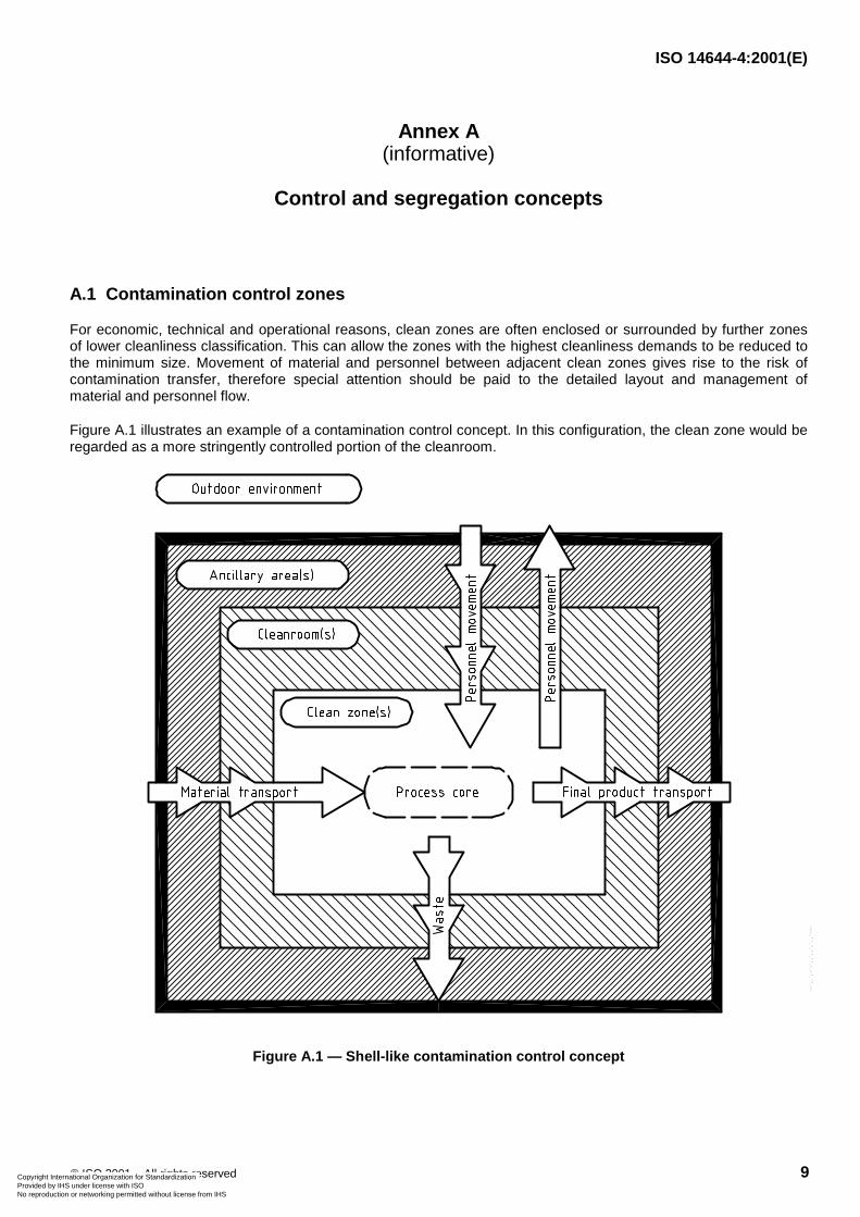
A.1 Contamination control zones
For economic, technical and operational reasons, clean zones are often enclosed or surrounded by further zonesof lower cleanliness classification. This can allow the zones with the highest cleanliness demands to be reduced tothe minimum size. Movement of material and personnel between adjacent clean zones gives rise to the risk ofcontamination transfer, therefore special attention should be paid to the detailed layout and management ofmaterial and personnel flow.
Figure A.1 illustrates an example of a contamination control concept. In this configuration, the clean zone would beregarded as a more stringently controlled portion of the cleanroom.
Figure A.1 — Shell-like contamination control concept
Copyright International Organization for Standardization Provided by IHS under license with ISO
Not for ResaleNo reproduction or networking permitted without license from IHS
--`,,`,-`-`,,`,,`,`,,`---
ISO 14644-4:2001(E)
10 © ISO 2001 – All rights reserved
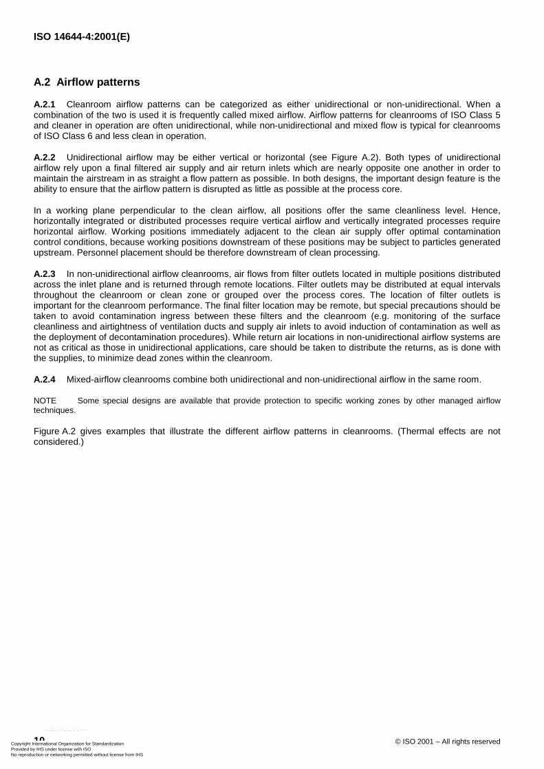
A.2 Airflow patterns
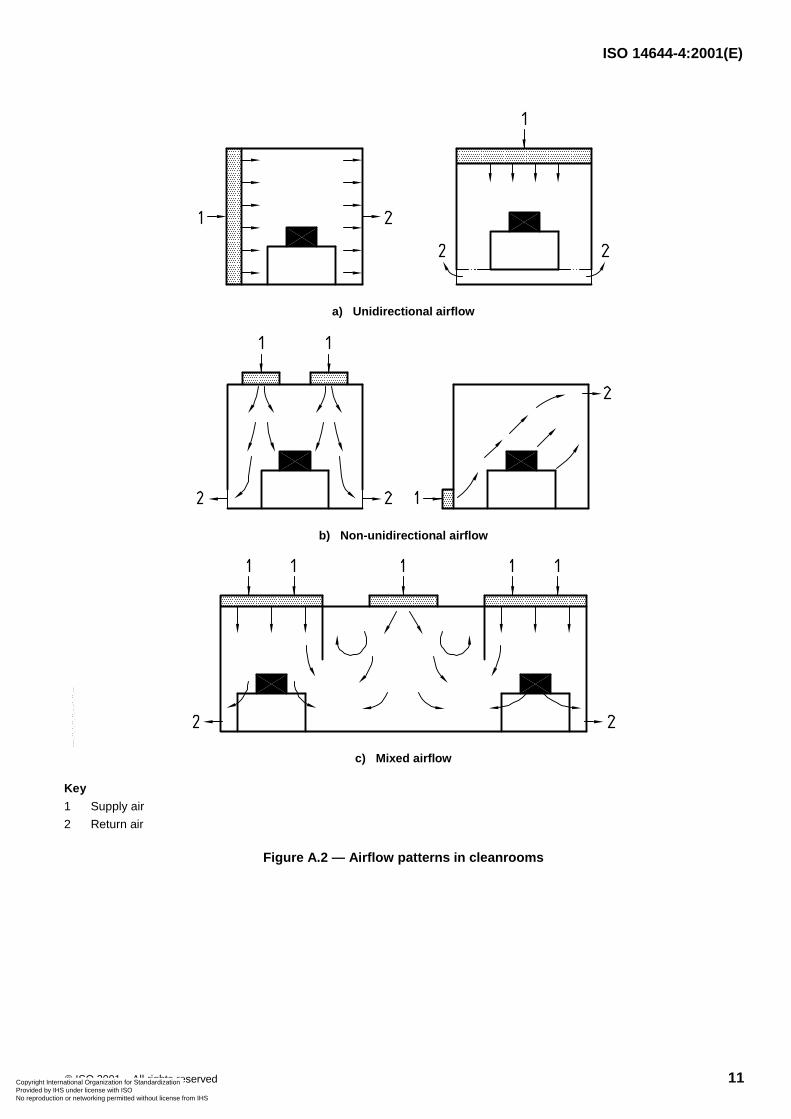
A.2.1 Cleanroom airflow patterns can be categorized as either unidirectional or non-unidirectional. When acombination of the two is used it is frequently called mixed airflow. Airflow patterns for cleanrooms of ISO Class 5and cleaner in operation are often unidirectional, while non-unidirectional and mixed flow is typical for cleanroomsof ISO Class 6 and less clean in operation.
A.2.2 Unidirectional airflow may be either vertical or horizontal (see Figure A.2). Both types of unidirectionalairflow rely upon a final filtered air supply and air return inlets which are nearly opposite one another in order tomaintain the airstream in as straight a flow pattern as possible. In both designs, the important design feature is theability to ensure that the airflow pattern is disrupted as little as possible at the process core.
In a working plane perpendicular to the clean airflow, all positions offer the same cleanliness level. Hence,horizontally integrated or distributed processes require vertical airflow and vertically integrated processes requirehorizontal airflow. Working positions immediately adjacent to the clean air supply offer optimal contaminationcontrol conditions, because working positions downstream of these positions may be subject to particles generatedupstream. Personnel placement should be therefore downstream of clean processing.
A.2.3 In non-unidirectional airflow cleanrooms, air flows from filter outlets located in multiple positions distributedacross the inlet plane and is returned through remote locations. Filter outlets may be distributed at equal intervalsthroughout the cleanroom or clean zone or grouped over the process cores. The location of filter outlets isimportant for the cleanroom performance. The final filter location may be remote, but special precautions should betaken to avoid contamination ingress between these filters and the cleanroom (e.g. monitoring of the surfacecleanliness and airtightness of ventilation ducts and supply air inlets to avoid induction of contamination as well asthe deployment of decontamination procedures). While return air locations in non-unidirectional airflow systems arenot as critical as those in unidirectional applications, care should be taken to distribute the returns, as is done withthe supplies, to minimize dead zones within the cleanroom.
A.2.4 Mixed-airflow cleanrooms combine both unidirectional and non-unidirectional airflow in the same room.
NOTE Some special designs are available that provide protection to specific working zones by other managed airflowtechniques.
Figure A.2 gives examples that illustrate the different airflow patterns in cleanrooms. (Thermal effects are notconsidered.)
Copyright International Organization for Standardization Provided by IHS under license with ISO
Not for ResaleNo reproduction or networking permitted without license from IHS
--`,,`,-`-`,,`,,`,`,,`---
ISO 14644-4:2001(E)
© ISO 2001 – All rights reserved 11
a) Unidirectional airflow
b) Non-unidirectional airflow
c) Mixed airflow
Key
1 Supply air
2 Return air
Figure A.2 — Airflow patterns in cleanrooms
Copyright International Organization for Standardization Provided by IHS under license with ISO
Not for ResaleNo reproduction or networking permitted without license from IHS
--`,,`,-`-`,,`,,`,`,,`---
ISO 14644-4:2001(E)
12 © ISO 2001 – All rights reserved
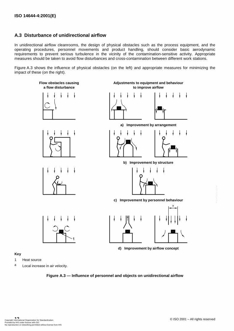
A.3 Disturbance of unidirectional airflow
In unidirectional airflow cleanrooms, the design of physical obstacles such as the process equipment, and theoperating procedures, personnel movements and product handling, should consider basic aerodynamicrequirements to prevent serious turbulence in the vicinity of the contamination-sensitive activity. Appropriatemeasures should be taken to avoid flow disturbances and cross-contamination between different work stations.
Figure A.3 shows the influence of physical obstacles (on the left) and appropriate measures for minimizing theimpact of these (on the right).
Flow obstacles causinga flow disturbance
Adjustments to equipment and behaviourto improve airflow
a) Improvement by arrangement
b) Improvement by structure
c) Improvement by personnel behaviour
d) Improvement by airflow concept
Key
1 Heat sourcea Local increase in air velocity.
Figure A.3 — Influence of personnel and objects on unidirectional airflow
Copyright International Organization for Standardization Provided by IHS under license with ISO
Not for ResaleNo reproduction or networking permitted without license from IHS
--`,,`,-`-`,,`,,`,`,,`---
ISO 14644-4:2001(E)
© ISO 2001 – All rights reserved 13
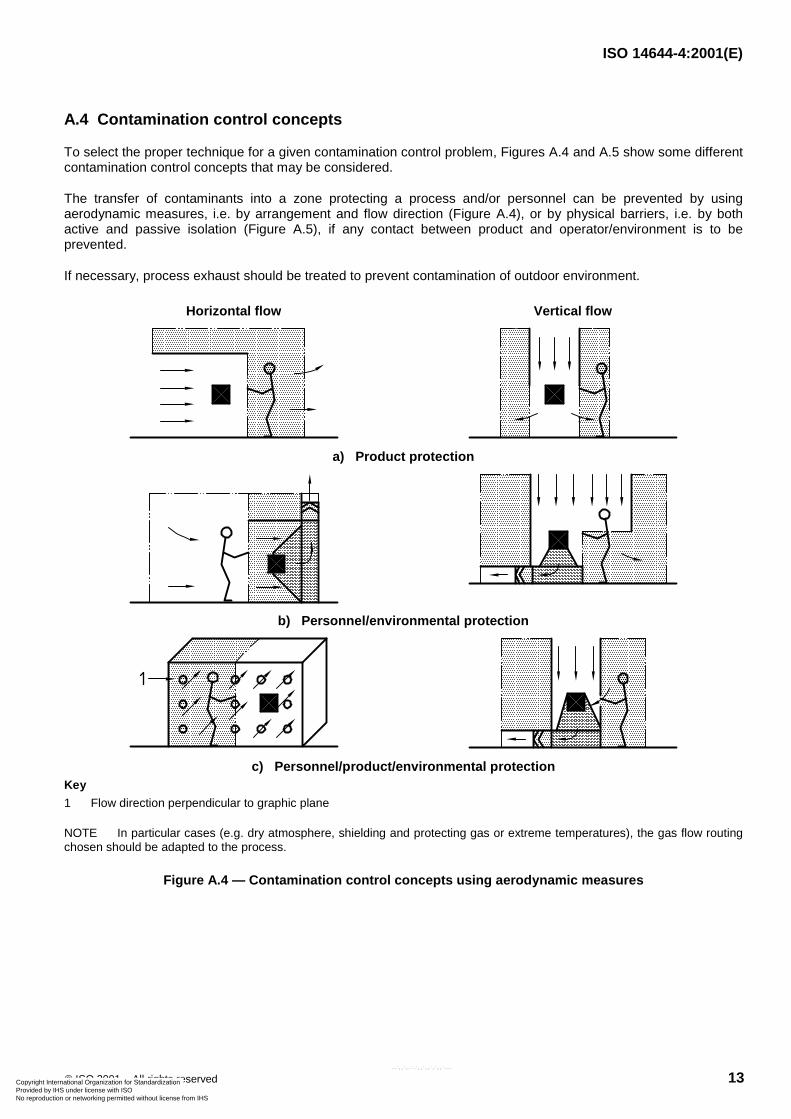
A.4 Contamination control concepts
To select the proper technique for a given contamination control problem, Figures A.4 and A.5 show some differentcontamination control concepts that may be considered.
The transfer of contaminants into a zone protecting a process and/or personnel can be prevented by usingaerodynamic measures, i.e. by arrangement and flow direction (Figure A.4), or by physical barriers, i.e. by bothactive and passive isolation (Figure A.5), if any contact between product and operator/environment is to beprevented.
If necessary, process exhaust should be treated to prevent contamination of outdoor environment.
Horizontal flow Vertical flow
a) Product protection
b) Personnel/environmental protection
c) Personnel/product/environmental protectionKey
1 Flow direction perpendicular to graphic plane
NOTE In particular cases (e.g. dry atmosphere, shielding and protecting gas or extreme temperatures), the gas flow routingchosen should be adapted to the process.
Figure A.4 — Contamination control concepts using aerodynamic measures
Copyright International Organization for Standardization Provided by IHS under license with ISO
Not for ResaleNo reproduction or networking permitted without license from IHS
--`,,`,-`-`,,`,,`,`,,`---
ISO 14644-4:2001(E)
14 © ISO 2001 – All rights reserved
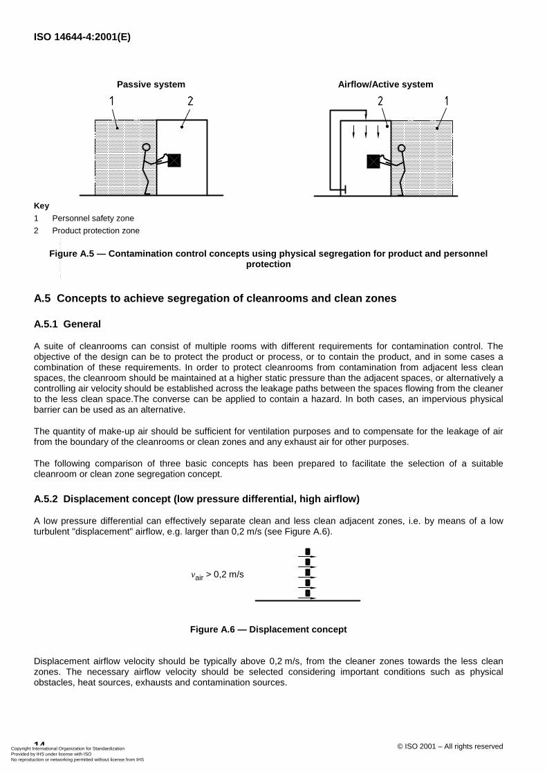
Passive system Airflow/Active system
Key
1 Personnel safety zone
2 Product protection zone
Figure A.5 — Contamination control concepts using physical segregation for product and personnelprotection
A.5 Concepts to achieve segregation of cleanrooms and clean zones
A.5.1 General
A suite of cleanrooms can consist of multiple rooms with different requirements for contamination control. Theobjective of the design can be to protect the product or process, or to contain the product, and in some cases acombination of these requirements. In order to protect cleanrooms from contamination from adjacent less cleanspaces, the cleanroom should be maintained at a higher static pressure than the adjacent spaces, or alternatively acontrolling air velocity should be established across the leakage paths between the spaces flowing from the cleanerto the less clean space.The converse can be applied to contain a hazard. In both cases, an impervious physicalbarrier can be used as an alternative.
The quantity of make-up air should be sufficient for ventilation purposes and to compensate for the leakage of airfrom the boundary of the cleanrooms or clean zones and any exhaust air for other purposes.
The following comparison of three basic concepts has been prepared to facilitate the selection of a suitablecleanroom or clean zone segregation concept.
A.5.2 Displacement concept (low pressure differential, high airflow)
A low pressure differential can effectively separate clean and less clean adjacent zones, i.e. by means of a lowturbulent "displacement" airflow, e.g. larger than 0,2 m/s (see Figure A.6).
vair > 0,2 m/s
Figure A.6 — Displacement concept
Displacement airflow velocity should be typically above 0,2 m/s, from the cleaner zones towards the less cleanzones. The necessary airflow velocity should be selected considering important conditions such as physicalobstacles, heat sources, exhausts and contamination sources.
Copyright International Organization for Standardization Provided by IHS under license with ISO
Not for ResaleNo reproduction or networking permitted without license from IHS
--`,,`,-`-`,,`,,`,`,,`---
ISO 14644-4:2001(E)
© ISO 2001 – All rights reserved 15
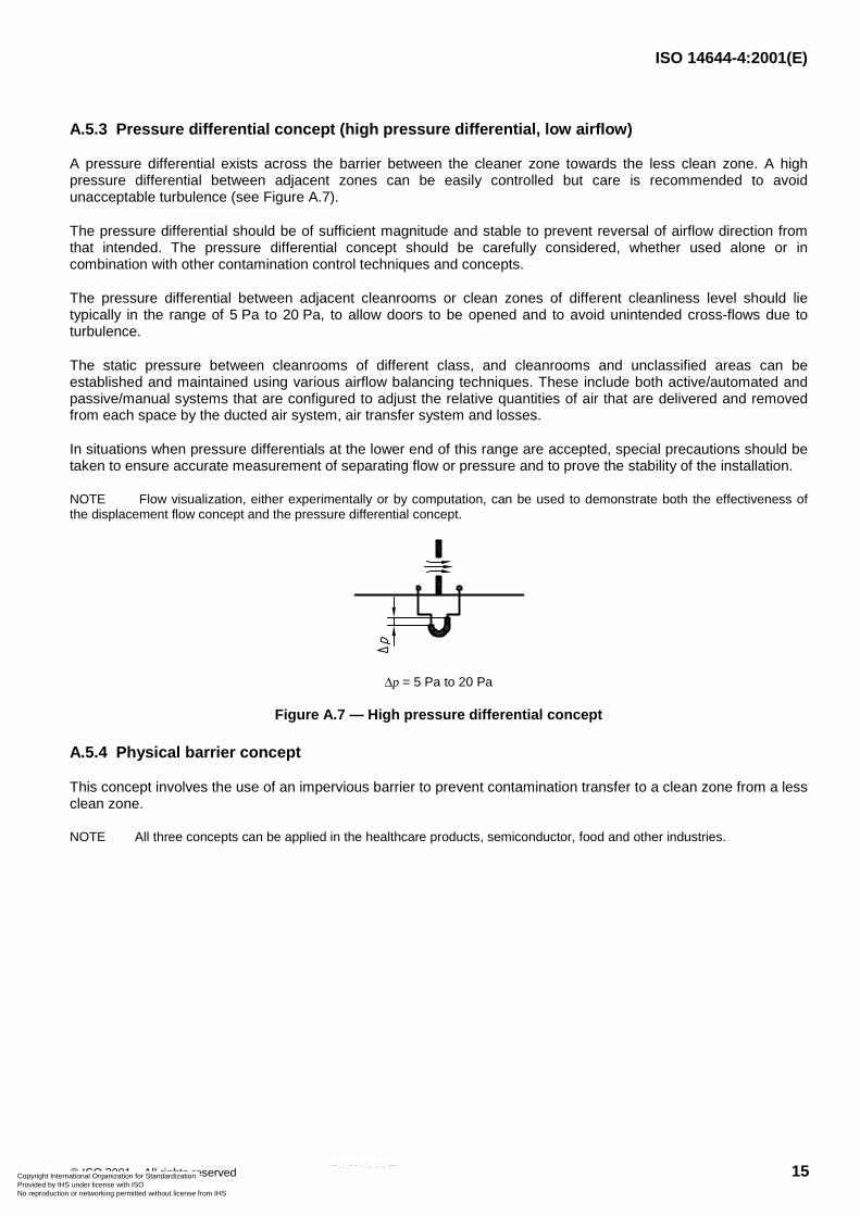
A.5.3 Pressure differential concept (high pressure differential, low airflow)
A pressure differential exists across the barrier between the cleaner zone towards the less clean zone. A highpressure differential between adjacent zones can be easily controlled but care is recommended to avoidunacceptable turbulence (see Figure A.7).
The pressure differential should be of sufficient magnitude and stable to prevent reversal of airflow direction fromthat intended. The pressure differential concept should be carefully considered, whether used alone or incombination with other contamination control techniques and concepts.
The pressure differential between adjacent cleanrooms or clean zones of different cleanliness level should lietypically in the range of 5 Pa to 20 Pa, to allow doors to be opened and to avoid unintended cross-flows due toturbulence.
The static pressure between cleanrooms of different class, and cleanrooms and unclassified areas can beestablished and maintained using various airflow balancing techniques. These include both active/automated andpassive/manual systems that are configured to adjust the relative quantities of air that are delivered and removedfrom each space by the ducted air system, air transfer system and losses.
In situations when pressure differentials at the lower end of this range are accepted, special precautions should betaken to ensure accurate measurement of separating flow or pressure and to prove the stability of the installation.
NOTE Flow visualization, either experimentally or by computation, can be used to demonstrate both the effectiveness ofthe displacement flow concept and the pressure differential concept.
�p = 5 Pa to 20 Pa
Figure A.7 — High pressure differential concept
A.5.4 Physical barrier concept
This concept involves the use of an impervious barrier to prevent contamination transfer to a clean zone from a lessclean zone.
NOTE All three concepts can be applied in the healthcare products, semiconductor, food and other industries.
Copyright International Organization for Standardization Provided by IHS under license with ISO
Not for ResaleNo reproduction or networking permitted without license from IHS
--`,,`,-`-`,,`,,`,`,,`---
ISO 14644-4:2001(E)
16 © ISO 2001 – All rights reserved
Annex B(informative)
Classification examples
B.1 Healthcare products
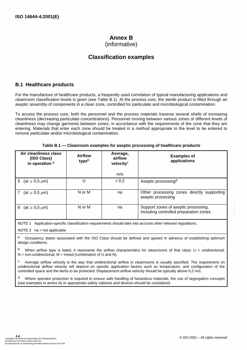
For the manufacture of healthcare products, a frequently used correlation of typical manufacturing applications andcleanroom classification levels is given (see Table B.1). At the process core, the sterile product is filled through anaseptic assembly of components in a clean zone, controlled for particulate and microbiological contamination.
To access the process core, both the personnel and the process materials traverse several shells of increasingcleanliness (decreasing particulate concentrations). Personnel moving between various zones of different levels ofcleanliness may change garments between zones, in accordance with the requirements of the zone that they areentering. Materials that enter each zone should be treated in a method appropriate to the level to be entered toremove particulate and/or microbiological contamination.
Table B.1 — Cleanroom examples for aseptic processing of healthcare products
Air cleanliness class(ISO Class)
in operation a
Airflowtypeb
Average,airflow
velocityc
Examples ofapplications
m/s
5 (at W 0,5 �m) U > 0,2 Aseptic processingd
7 (at W 0,5 �m) N or M na Other processing zones directly supportingaseptic processing
8 (at W 0,5 �m) N or M na Support zones of aseptic processing,including controlled preparation zones
NOTE 1 Application-specific classification requirements should take into account other relevant regulations.
NOTE 2 na = not applicable
a Occupancy states associated with the ISO Class should be defined and agreed in advance of establishing optimumdesign conditions.
b When airflow type is listed, it represents the airflow characteristics for cleanrooms of that class: U = unidirectional;N = non-unidirectional; M = mixed (combination of U and N).
c Average airflow velocity is the way that unidirectional airflow in cleanrooms is usually specified. The requirement onunidirectional airflow velocity will depend on specific application factors such as temperature, and configuration of thecontrolled space and the items to be protected. Displacement airflow velocity should be typically above 0,2 m/s.
d Where operator protection is required to ensure safe handling of hazardous materials, the use of segregation concepts(see examples in annex A) or appropriate safety cabinets and devices should be considered.
Copyright International Organization for Standardization Provided by IHS under license with ISO
Not for ResaleNo reproduction or networking permitted without license from IHS
--`,,`,-`-`,,`,,`,`,,`---
ISO 14644-4:2001(E)
© ISO 2001 – All rights reserved 17
B.2 Microelectronics
In the microelectronics industry, the minimum device feature size or film thickness dictates the target level ofcontamination control and the corresponding cleanliness class.
The cleanliness class with the lowest particle concentration is often selected with reference to the critical particlesize. The critical particle size (often assumed to be 1/10th of the minimum feature size) is used to help select therequired cleanliness classification for the cleanroom.
Determination of cleanroom or clean zone cleanliness for different process cores is based upon the probability ofcontamination and the potential for device failure.
For example, photolithography is a process which involves exposure of wafers to the environment with a highprobability of contamination and also a very high potential for device failure when contamination occurs.Accordingly, protection in microelectronics for this type of risk often involves the use of physical barriers whichprotect process cores in order to lower particle concentrations or alter other process parameters (e.g. temperature,humidity, pressure).
Work zones are zones where wafers or die are handled by people and/or automated handling equipment, and thepotential for contamination is high if the product is directly exposed to the environment. The most commonresponses for the protection of the product within work zones involve unidirectional flow, minimizing occupancy andproduction load per cubic meter of cleanroom, segregating personnel from exposed product(s) increasinglyincluding barrier techniques. Work zones are most commonly separated from adjacent, less critical zones, byphysical barriers and airflow.
Utility zones are zones where the non-operator interface portions of the wafer processing equipment are typicallylocated. In the utility zones it is typical that work in progress is not exposed to the environment. The utility zone of aprocess core is usually adjacent to its corresponding work zone.
Service zones are zones where neither product nor process equipment are located, but service zones are sitednext to work or utility zones to help separate the cleaner zones from the less clean zone (see Table B.2).
B.3 Influence of cleanroom clothing
The number of personnel and the type of cleanroom clothing may require specific consideration with respect to particleemission (see relevant parts of this International Standard, e.g. ISO 14644-5).
Copyright International Organization for Standardization Provided by IHS under license with ISO
Not for ResaleNo reproduction or networking permitted without license from IHS
--`,,`,-`-`,,`,,`,`,,`---
ISO 14644-4:2001(E)
18 © ISO 2001 – All rights reserved
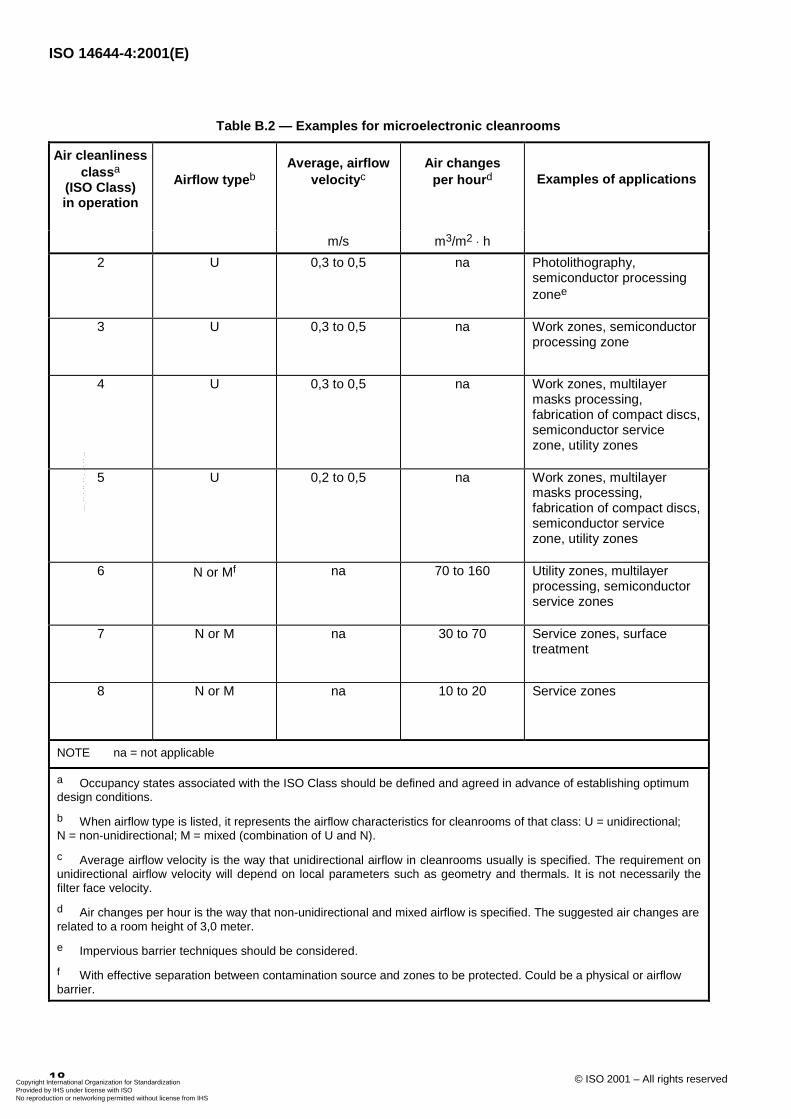
Table B.2 — Examples for microelectronic cleanrooms
Air cleanlinessclassa
(ISO Class)in operation
Airflow typebAverage, airflow
velocitycAir changes
per hourd Examples of applications
m/s m3/m2� h
2 U 0,3 to 0,5 na Photolithography,semiconductor processingzonee
3 U 0,3 to 0,5 na Work zones, semiconductorprocessing zone
4 U 0,3 to 0,5 na Work zones, multilayermasks processing,fabrication of compact discs,semiconductor servicezone, utility zones
5 U 0,2 to 0,5 na Work zones, multilayermasks processing,fabrication of compact discs,semiconductor servicezone, utility zones
6 N or Mf na 70 to 160 Utility zones, multilayerprocessing, semiconductorservice zones
7 N or M na 30 to 70 Service zones, surfacetreatment
8 N or M na 10 to 20 Service zones
NOTE na = not applicable
a Occupancy states associated with the ISO Class should be defined and agreed in advance of establishing optimumdesign conditions.
b When airflow type is listed, it represents the airflow characteristics for cleanrooms of that class: U = unidirectional;N = non-unidirectional; M = mixed (combination of U and N).
c Average airflow velocity is the way that unidirectional airflow in cleanrooms usually is specified. The requirement onunidirectional airflow velocity will depend on local parameters such as geometry and thermals. It is not necessarily thefilter face velocity.
d Air changes per hour is the way that non-unidirectional and mixed airflow is specified. The suggested air changes arerelated to a room height of 3,0 meter.
e Impervious barrier techniques should be considered.
f With effective separation between contamination source and zones to be protected. Could be a physical or airflowbarrier.
Copyright International Organization for Standardization Provided by IHS under license with ISO
Not for ResaleNo reproduction or networking permitted without license from IHS
--`,,`,-`-`,,`,,`,`,,`---
ISO 14644-4:2001(E)
© ISO 2001 – All rights reserved 19
Annex C(informative)
Approval of an installation
C.1 Test preparation and final cleaning
Prior to carrying out any inspection, test or measurement procedure, running systems should be allowed time toreach stability; this period of time should be agreed upon in advance. Tests should be of sufficient duration todemonstrate consistent performance (see clause 4, and examples in annex H).
Prior to the fitting of filters and after cleaning as described in E.1.2/E.3.3 in annex E has been completed, all ducts,walls, ceilings, floors and installed fittings should be cleaned to remove contamination which could prejudice theclassification of the cleanroom.
Following cleaning, the final filters should be fitted and the commissioning tests conducted to demonstratecompliance.
C.2 Inspection, tests and approvals
C.2.1 General
In order to demonstrate that an installation is complete in every respect and performs to meet all contaminationcontrol requirements included in clause 4, a specific range of inspections and tests should be carried out upon theinstallation in question. Typical activities are identified in C.2.2 to C.2.5 and Figure C.1 for graphic representation.
C.2.2 Concept and design approval
A check should be carried out to ensure that the concept, design, and developed details satisfy the agreementsbetween the purchaser and supplier. Review should include at least:
a) contamination control concept;
b) layout of equipment;
c) description of the installation;
d) schemes and drawings;
e) incorporation of all other agreed requirements.
C.2.3 Construction and installation approval
C.2.3.1 Construction approval (at supplier's site)
A check should be carried out to ensure that the components and assemblies comply with the design. The checkshould include at least the following items:
a) inspection and testing for completeness and quality according to specification;
Copyright International Organization for Standardization Provided by IHS under license with ISO
Not for ResaleNo reproduction or networking permitted without license from IHS
--`,,`,-`-`,,`,,`,`,,`---
ISO 14644-4:2001(E)
20 © ISO 2001 – All rights reserved
b) approval for compliance with safety regulations, ergonomic requirements, relevant guidelines and normativeregulations;
c) approval of certificates.
C.2.3.2 Installation approval (at the site of the installation)
A check should be carried out to ensure that the construction of the installation complies with the design. The checkshould include in addition to C.2.3.1 at least the following items:
a) completeness of the installation;
b) interfaces with other suppliers;
c) correct function of utilities and auxiliary equipment;
d) calibration of all control, monitoring, warning and alarm systems;
e) fitting and in-situ testing of final filters;
f) proving the reserve capacity of the air treatment system;
g) testing enclosure for leakage;
h) confirming that the proportion of recirculation to make-up air complies with the design specification;
i) surface cleanliness and suitability of the installation (see examples in annex E);
j) spare parts package.
C.2.4 Functional approval
After having completed the checks and approvals according to C.2.3.2, at least the following functional tests shouldbe performed:
a) determine clean zone segregation;
b) measure and record contamination control recovery time;
c) determine ability to maintain temperature and relative humidity requirements;
d) determine airborne particulate cleanliness class;
e) where appropriate, determine particulate surface cleanliness and microbiological contamination levels;
f) determine light and noise levels;
g) demonstrate and record airflow patterns and air change rate if necessary.
C.2.5 Operational approval (equipment installed in a manner agreed in advance)
Certain of the previous tests may be repeated to determine compliance with the operational conditions, namely:
a) confirm clean zone segregation regime;
b) determine ability to maintain temperature and relative humidity;
c) determine airborne particulate cleanliness class;
Copyright International Organization for Standardization Provided by IHS under license with ISO
Not for ResaleNo reproduction or networking permitted without license from IHS
--`,,`,-`-`,,`,,`,`,,`---
ISO 14644-4:2001(E)
© ISO 2001 – All rights reserved 21
d) where appropriate, determine particulate surface cleanliness and microbiological contamination levels;
e) check the completeness of documentation according to clause 8.
For compliance-related issues, refer to ISO 14644-2; for microbiological-related issues, refer to ISO 14698-1,ISO 14698-2 and ISO 14698-3; for testing-related issues and for operational-related issues, refer to other relevantparts of this International Standard.
C.3 Reports
The reports of the tests should be presented in a documented manual. This manual should include:
a) supplier's test documentation;
b) calibration certificates of instrumentation used;
c) relevant drawings and as-installed details;
d) witnessed verification of compliance with specification.
Copyright International Organization for Standardization Provided by IHS under license with ISO
Not for ResaleNo reproduction or networking permitted without license from IHS
--`,,`,-`-`,,`,,`,`,,`---
ISO 14644-4:2001(E)
22 © ISO 2001 – All rights reserved
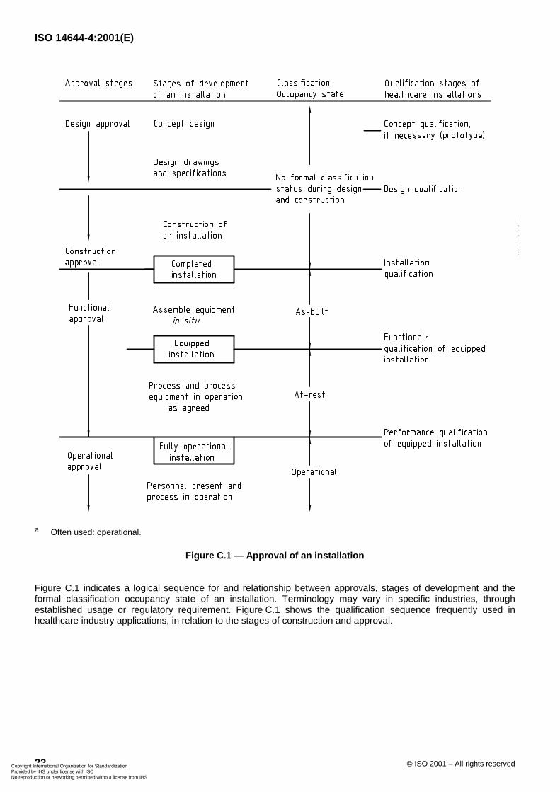
a Often used: operational.
Figure C.1 — Approval of an installation
Figure C.1 indicates a logical sequence for and relationship between approvals, stages of development and theformal classification occupancy state of an installation. Terminology may vary in specific industries, throughestablished usage or regulatory requirement. Figure C.1 shows the qualification sequence frequently used inhealthcare industry applications, in relation to the stages of construction and approval.
Copyright International Organization for Standardization Provided by IHS under license with ISO
Not for ResaleNo reproduction or networking permitted without license from IHS
--`,,`,-`-`,,`,,`,`,,`---
ISO 14644-4:2001(E)
© ISO 2001 – All rights reserved 23
Annex D(informative)
Layout of an installation
D.1 General considerations
D.1.1 Size
The size of a cleanroom should be kept to the minimum practicable, allowing for any future requirements. Ingeneral, if a large amount of space is required, it should be divided into several zones or rooms, with or withoutphysical barriers.
NOTE It is recognized that the presence of people, and activity, within a cleanroom can generate both contamination anddisturbance of airflow. Annex B provides examples of installation configurations to control these phenomena. Annex A discussescontamination control concepts in which airflow and the physical configuration of a workstation or other critical discrete areasare managed to obviate or minimize exchange of contamination between product and its environment, including people in theimmediate proximity.
D.1.2 Workstation siting and organization
Within the cleanroom, critical workstations or areas of risk should be sited away from entries and exits, major trafficpathways and other features which may cause disruption of the airflow pattern and higher levels of contamination.
In horizontal-flow cleanrooms, the siting of workstations should be such that the clean work which is to beperformed receives clean air from the appropriate source, without flow disturbance or contamination from personnelmovements or adjacent work.
When operations that require different degrees of cleanliness are to be carried out in an area swept by horizontalunidirectional airflow, less clean operations should be sited downstream of cleaner operations, insofar as it can bedetermined that this arrangement will not compromise the maintaining of target conditions for any critical points.
D.1.3 Ancillary areas and adjacent cleanrooms
Consideration should be given to the location and integration of ancillary areas such as service and utility, cleaning,preparation, toilet and refreshment facilities, in order to avoid compromise of the critical conditions maintainedwithin the cleanrooms. Pressure or flow differentials, access and communication arrangements (such as airlocks,speech panels and intercoms), enclosure sealing (notably material joints, equipment and utility penetrations) shouldbe executed so that cross-contamination from less clean zones does not compromise the cleaner zones. Layoutshould combine with effective training and management of personnel behaviour to minimize disturbance and cross-contamination due to movement between ancillary areas and cleanrooms.
D.1.4 Utility services and ancillary equipment
D.1.4.1 General
Utility services provided for the cleanroom should be designed, located and installed such that the cleanroom is notcompromised by contamination from such services.
In general, exposed piping, tubing and cable runs within the cleanroom should be minimized, as these may presentproblems for adequate cleaning, and may be sources of damage by contact with cleanroom garments, wipes, etc.This should be balanced against the potential for contamination within protective housings, covers, etc., which mayalso hinder disinfection or fumigation. Where possible, consideration should be given to the routing of such services
Copyright International Organization for Standardization Provided by IHS under license with ISO
Not for ResaleNo reproduction or networking permitted without license from IHS
--`,,`,-`-`,,`,,`,`,,`---
ISO 14644-4:2001(E)
24 © ISO 2001 – All rights reserved
in external service areas or ducts. Means should be provided for the effective removal of waste and contaminationgenerated within such spaces.
Power take-off points, taps and connections should be designed and installed to facilitate regular cleaning, and toavoid the build-up of contamination in or behind blanking covers. Wherever possible, maintenance activities shouldbe performed outside the cleanroom. Pressure or flow differentials, access arrangements (notably airlocks andtransfer hatches), enclosure sealing (notably material joints, equipment and utility penetrations) should be executedso that cross-contamination from ancillary areas does not compromise the cleanroom.
The number, type and location of utility services should be agreed between the purchaser and supplier.
D.1.4.2 Vacuum-cleaning equipment
Vacuum-cleaning equipment, either portable or built-in, should be provided to ensure that particulate contaminationcan be removed during periodic cleaning, and to ensure that contamination generated by any operation that cannotreasonably be conducted outside the cleanroom can be removed efficiently, and with appropriate frequency.
Where a permanent vacuum-cleaning system is provided, the exhaust and fan should be sited outside thecleanroom. The connection sockets in the cleanroom should be blanked off when not in use. The airflow throughthe vacuum chamber should not compromise the differential pressure or the airflow configuration of the cleanroom.
When portable vacuum equipment is used, it should be fitted with an exhaust filter of at least the same efficiency asthat filtering the environmental air supply, and care should be taken to consider the influence upon air patterns inthe cleanroom.
D.1.4.3 Sprinkler systems
Fire control systems present special problems, notably in the routing of supply piping containing a fire suppressantmedium, whether water, chemical substance or gas, which is a potential contaminant of the cleanrooms, and apotential source of damage to the components of the installation, in the event of accidental or deliberate release.
When sprinkler piping is to run above ceilings, careful consideration should be given to its routing, in relation to theequipment and operations sited in the cleanroom below. Adequate access should be provided for maintenance andmodification, and consideration should be given to provision of means to collect and evacuate fluid leaked orreleased above the ceiling.
Penetration of walls or ceilings for supply to sprinkler points should be sealed as appropriate, like all otherpenetrations of the cleanroom. The sprinkler heads themselves should be situated and shaped for minimumintrusion into the cleanroom, and for minimal disturbance of clean airflow, insofar as this is compatible with theirprimary safety function. Where disturbance is inevitable, appropriate measures should be taken to avoid anyundesirable effect upon the required integrity of the cleanroom conditions.
D.1.5 Communication systems
Wherever practical, communication systems should be provided in order to minimize movement of personnel intoand out of the cleanroom. Windows, speech panels, intercoms, data links and telephones are suitable means ofcommunication. They should be selected to be compatible with the cleanroom class and application considerations.
D.1.6 Glazing
Where windows to the outside are a requirement, care should be taken, in design and fitting, to avoid undue heatloss, solar gain and condensation. The use of windows to adjoining inside spaces should be considered, to allowobservation of activity within the room, without entry. Windows should be non-opening and sealed. Double glazingcan be used to achieve flush fitting, and also enables provision of interstitial shutters or blinds. The use of exposedblinds within a cleanroom should be avoided.
Copyright International Organization for Standardization Provided by IHS under license with ISO
Not for ResaleNo reproduction or networking permitted without license from IHS
--`,,`,-`-`,,`,,`,`,,`---
ISO 14644-4:2001(E)
© ISO 2001 – All rights reserved 25
D.2 Access
D.2.1 General
The number of openings connecting the cleanroom to outside, or adjoining, areas should be minimized.
Effective means should be taken to minimize the contamination arising from the entry or exit of personnel ormaterial, or from air movement. Normal (non-emergency) access to or from the cleanroom should be throughairlocks for both personnel and material.
D.2.2 Airlocks
In order to maintain pressure differential and integrity of the controlled space during entry and exit, airlocks ortransfer hatches (pass-throughs) are normally required.
Precautions should be taken to ensure that entry and exit doors associated with an airlock are not openedsimultaneously. Clear windows can be provided at both points to allow a line-of-sight view between them.Consideration should be given to the use of electrical or mechanical interlock systems including audio-visualindicators.
Barrier benches or other clear demarcation systems, together with appropriate decontamination devices andprocedures, should be employed within an airlock system for the passage of material. The passage of material andpersonnel can be segregated.
D.2.3 Emergency exits
Emergency exits should be provided with means to show that they have been opened.
D.2.4 Changing rooms
D.2.4.1 General
Changing rooms are specialized airlocks for the entry and exit of personnel to and from a cleanroom. They shouldinclude sufficient space for their function, and, depending on the cleanroom quality, facilities for donning andremoving specialized garments, and may include washing, disinfection facilities, etc. Special contamination controlequipment such as air showers, shoe cleaners and adhesive floor materials may be provided at the point(s) of entryand exit to the cleanroom.
Separation of the personnel entering from those leaving the cleanroom via the changing room should be ensured.This can be achieved by separation in time, or by providing physically separate entry and exit routes.
Where hazardous materials are processed, a separate changing and decontamination route should be considered.
D.2.4.2 Changing room control and configuration
Changing rooms should be provided with a level of contamination control and environmental control that ensuresthe integrity of the cleanroom. Similarly, the methods and equipment for storage of garments and equipment for usein the cleanroom should be commensurate with the required cleanliness and contamination protection required bythe contamination-sensitive operation. To provide the required protection, consideration should be given to threefunctional zones of the changing room:
a) at the changing room entry: access from ancillary areas (either directly or via an airlock) appropriate forremoval, storage, disposal and/or redonning of garments not permitted within the cleanroom;
b) the transition zone: area where garments or personal equipment dedicated to the cleanroom are stored,donned or removed, as appropriate;
Copyright International Organization for Standardization Provided by IHS under license with ISO
Not for ResaleNo reproduction or networking permitted without license from IHS
--`,,`,-`-`,,`,,`,`,,`---
ISO 14644-4:2001(E)
26 © ISO 2001 – All rights reserved
c) the inspection/access zone: area where inspection of the completed gowning process is accomplished andwhich provides access to the cleanroom either directly or via an airlock.
The three functional zones may be separated by a physical barrier (e.g. a stepover bench or airlock) as appropriateto the operation and use of the changing room. The three zones should be established, such that the zone closestto the cleanroom provides a high degree of assurance, and that minimal adverse impact is caused by access orgowning procedures implemented in the adjacent zone.
D.2.4.3 Facilities in changing rooms
The features provided in the changing room are particular to the cleanroom that the changing room serves.
The following requirements should be defined:
� number of people passing through the gowning procedure, both in the absolute, and at any one time;
� the gowning procedure (i.e. what garments are to be taken off and put on, whether these are reusable orsingle-use, the required protocol to ensure garment cleanliness and to avoid cross-contamination);
� the frequency of garment replacement.
Consideration should be given to the following provisions in the changing room:
a) storage and disposal of garments;
b) storage before use, provision and disposal of consumable items and accessories (e.g. gloves, masks,protective glasses, overshoes);
c) storage of personal items;
d) hand-washing and -drying or other decontamination processes;
e) prominent display or posting of gowning sequence, with clear instructions;
f) full-length mirrors to check effective fit.
Copyright International Organization for Standardization Provided by IHS under license with ISO
Not for ResaleNo reproduction or networking permitted without license from IHS
--`,,`,-`-`,,`,,`,`,,`---
ISO 14644-4:2001(E)
© ISO 2001 – All rights reserved 27
Annex E(informative)
Construction and materials
E.1 Selection of materials
E.1.1 General
The materials used in the construction of the installation should be selected and applied to meet the requirements ofthe installation, and should take into account the following:
a) the cleanliness class;
b) effects of abrasion and impact;
c) cleaning and disinfection methods and frequencies;
d) chemical/microbiological attack and corrosion.
Materials which may tend to break down or to shed particles should only be used when they are effectivelyencapsulated and protected.
Consideration should be given to the chemical compatibility of all materials used with the operating requirements ofthe installation. This may, for instance, influence the choice of adhesives and sealing mastics for surface-finishingwork, or of materials used for filter assembly and sealing.
All surfaces which come into contact with air supplied to the interior of the cleanroom or clean zone may by theirnature or condition influence the quality of the air supplied to the contamination-sensitive zones. For this reason,materials and finishes intended for the internal surfaces of the complete air-handling system should be criticallyassessed and specifically approved for this purpose.
All exposed surfaces of equipment, furnishings and material present within the cleanroom or clean zone should meetthe same criteria as the exposed structural elements of the installation.
Further details of specific performance criteria follow.
E.1.2 Surface cleanliness and cleanability of materials of construction
All exposed materials should be suitable for effective and frequent cleaning and disinfection, and offer no surfaceasperities or porosity which are likely to allow retention of particulate and chemical contamination, or the developmentof microbiological contamination. Methods for selecting, applying and controlling suitable procedures for cleaning anddisinfection are indicated in ISO 14698-1 and ISO 14698-3, and other relevant parts of this International Standard.Appropriate methods for assessing and monitoring surface cleanliness (for instance in terms of releasable particulate,biological and chemical contamination) should be selected and approved for the application. Exposed materialsshould be selected with due consideration of their resistance to the mechanical and chemical effects of the intendedmethods of cleaning and disinfection, in order to remain smooth, non-porous, abrasion- and stain-resistant (see alsoE.1.4 and E.3.3).
Walls, floors and ceilings in cleanrooms and in clean zones should be designed and constructed in such a way thatthe surfaces are accessible for cleaning. In a room, this generally includes the walls, floors, ceilings and doors, theinlet side of air diffusers and floor drain, etc. (see examples in annex G).
Copyright International Organization for Standardization Provided by IHS under license with ISO
Not for ResaleNo reproduction or networking permitted without license from IHS
--`,,`,-`-`,,`,,`,`,,`---
ISO 14644-4:2001(E)
28 © ISO 2001 – All rights reserved
When it is necessary to wipe down or wash walls, floors or ceilings on a frequent basis, consideration of the selectionof materials should include careful evaluation of the junction and intersection details, and in particular the avoidance ofplaces where moisture can be trapped or lie on surfaces.
E.1.3 Control of electrostatic charging and discharge
Accumulation of electrostatic charge, and subsequent electrostatic discharge, can present a risk of hazards suchas explosion (in the presence of powders or gases), device damage (e.g. damage to electronic or opticalcomponents), or excessive attraction of particles to surfaces contributing to physical, chemical and microbiologicalcontamination.
Where the above risks cause concern, materials used in the construction of installations should neither generate norhold a significant static charge. This significant value will be specific to each application, and should be clearlyspecified by the purchaser. Certain processes may require particular conditions in terms of environmental humidity, inorder to minimize the generation of electrostatic charge. Annex F provides further guidance on this technique. Itshould be noted that the most favourable humidity conditions for avoidance of electrostatic charge accumulation mayconflict with other requirements of the process, or project objectives. A solution should be agreed, which achieves anacceptable compromise. Certain applications may require the use of conductive or static dissipative materials in orderto minimize the influence of any induced static charge.
To protect electrostatically sensitive components the resistance to earth should be in the range of RE = 104� to
107�. Care should be taken to protect the personnel against risk of electrocution. Earthing should be considered, with
a site transition resistance RST = 5 � 104�. The "ideal" range of resistance is therefore between the site transition
resistance RST = 5 � 104� and the mass resistance RE = 107
�.
The required electrical characteristics for flooring are valid for the entire structure or composite of materials used asa floor, and should be measured regularly to monitor potential loss of performance through ageing. Limit values of2 kV (applicable to accumulated surface charge) should not be exceeded. Monitoring of wall conductivity should becarried out regularly and after modifications or repairs.
E.1.4 Internal finishes, durability and maintainability
In the completed installation, all internal surfaces should be finished suitably smooth, non-porous and free fromcracks, cavities, steps and ledges. The design and construction should be such that the number of steps, ledges,cavities and similar features where contamination could collect is minimized. The number of corners should also bekept to a minimum, particularly internal corners. Corners and junctions may be radiused, especially at floor-to-wall andwall-to-wall junctions, so that effective cleaning is facilitated. The finish should be compatible with the mechanical andchemical effects of the intended methods of cleaning and disinfection.
Materials used for internal finishes should be maintained to ensure that they consistently retain the performancequalities consistent with the cleanliness class of the installation. This may require regular maintenance proceduresand repairs. Consideration of maintenance and repair methods and disruption impact should form part of the materialselection criteria. Full lifecycle cost and contamination risk analysis procedures should be considered.
E.2 Considerations for specific components
E.2.1 Ceilings, walls and floors
E.2.1.1 Basic requirements
Wall, ceiling and floor elements should comply with all relevant regulations concerning fire protection, sound andthermal insulation. Surface finish and assembly details should be compatible with the specified cleaning methods. Inorder to avoid glare, consideration should be given to the interaction of surface colour and finish with the intendedlighting conditions. Airlocks, gowning rooms and material passage points should normally have at least the samerequirements as the cleaner of the zones they serve. In the case of equipment and material transfer airlocks,decontamination and "cleandown" procedures may impose special requirements.
Copyright International Organization for Standardization Provided by IHS under license with ISO
Not for ResaleNo reproduction or networking permitted without license from IHS
--`,,`,-`-`,,`,,`,`,,`---
ISO 14644-4:2001(E)
© ISO 2001 – All rights reserved 29
NOTE There are many acceptable methods and materials for constructing cleanrooms ranging from in situ construction tofully prefabricated site-assembled systems. The basic options are summarized as follows:
a) Prefabricated site-assembled systems and in situ construction:
1) wet construction with applied surface finish,
2) dry construction with applied surface finish.
b) In situ assembly:
1) pre-finished engineered components,
2) modular pre-finished panel system.
Combinations of these basic construction options can also be used.
The choice of method of construction of an installation should take into account not only the contamination control andoperational requirements, but also matters relating to the construction location (e.g. construction and finishing skillsavailable); considerations influenced by the available building envelope in which the installation is located, such asavailable height, load-bearing capability, deflection of structures; maintenance constraints and requirements such as"walk-on-ceiling" capability, etc.
E.2.1.2 Ceilings
Ceilings should be sealed, to prevent ingress of air bearing particles, or other contaminants, from the ceiling void.Filters, filter frames, filter housings and diffusers mounted in the ceiling should be sealed. Penetration points (e.g. forutility services, sprinklers and lighting) should be kept to the minimum required, and be sealed. Consideration shouldbe given to the location and configuration of components such as lights and sprinklers to avoid disturbance of theintended airflow.
E.2.1.3 Walls and wall systems
Materials and surface finishes should meet all general requirements for their application. Particular considerationshould be given to impact and abrasion resistance, especially in those locations exposed to frequent passage oftrolleys, carts or personnel carrying material likely to contact exposed surfaces of walls and doors. Suitable rubbingstrips or protective bars may constitute satisfactory protection of otherwise vulnerable material.
Some applications may require that walls or wall panels be sealed to prevent exchange of contaminants withsurrounding areas. Cover strips or seals between panels should be smooth, with rounded edges (some applicationsrequire flush fitting) to facilitate efficient cleaning and limit retention of contaminants. Particular attention should bepaid to smoothness and effective sealing of utility services or other penetrations.
Where glazing is required, in walls or doors, it should be of the non-opening type. Consideration should be given tothe use of double glazing, with airtight seal, which can enable flush mounting on both sides. If blinds or shutters arerequired, these should be fitted outside the clean zone, or between the glazed elements of double glazing. Glazingframes should be smooth. Where flush fitting is not required, rounded edges or sloping surfaces should beconsidered.
Doors should present as few horizontal surfaces as possible, with particular attention being paid to the minimization ofsteps and ledges in the door surface. Thresholds should be avoided. Consideration should be given to theminimization of abrasion in the mechanical elements of the door (e.g. latches, locks and hinges), and also betweenthe door and its frame and the floor. Door handles, where required, should be smooth, non-snagging and easy toclean. Consideration should be given to the use of push plates, automatic openings, or appropriate door-swingdirection where contamination transfer is a concern.
Copyright International Organization for Standardization Provided by IHS under license with ISO
Not for ResaleNo reproduction or networking permitted without license from IHS
--`,,`,-`-`,,`,,`,`,,`---
ISO 14644-4:2001(E)
30 © ISO 2001 – All rights reserved
E.2.1.4 Floors
Floors or floor coverings should be non-porous, slip-resistant, abrasion-resistant, conductive if necessary; resistant tothe chemicals they will encounter in use (both cleaning and disinfection products, and accidental spillage of processfluids) and easy to clean. The floor should support the specified static and dynamic loads with the required durability.The floor complex should provide the appropriate electrostatic characteristics.
E.2.2 Air-handling systems
Attention should be paid to minimizing the contamination generated, retained and released throughout the air-handling system, in all components and surfaces in contact with the system air, in order that an excessive load is notplaced on the filtration system. Ducts should be manufactured from materials with corrosion-resistant and non-flakingproperties, or should be given suitable surface treatment to prevent release of contaminants from the duct to the airpassing through. If there is no terminal filter outlet provided, the quality and integrity of the system downstream of thefinal filter is more important. The effects of leakage from air-handling systems should be considered.
E.2.3 Fittings in airlocks
Fittings in airlocks and gowning rooms should present as few horizontal surfaces as possible. For exampleconsideration should be given to the use of hanging rails and perforated shelf boards rather than closed lockers.Exposed surfaces should satisfy criteria similar to those specified for the interior of the cleanroom and clean zone,and may require additional specifications to ensure durability in this application.
E.2.4 Ancillary areas
These should have no direct connection to the cleanroom, except for emergency exits. Exposed surfaces in theseareas should be chosen with a particular concern for durability and ease of maintenance.
E.3 Construction and assembly
E.3.1 General
Construction work should comply with the drawings and specifications, and the agreed quality plan. Any changesrequired during the construction phase should be checked for acceptance, approved and documented prior to theirimplementation (see also examples in annex C).
E.3.2 Material management during construction
All components and materials for use in the construction and subsequent maintenance of the installation should bemanufactured, packed, transported, stored and inspected before use in such a manner as to ensure their suitability fortheir intended use.
E.3.3 Cleanliness and cleaning during construction and start-up
Many tasks involved in construction and assembly intrinsically generate contamination. A clean construction protocolshould be developed and enforced to satisfy and achieve the specified contamination control objectives. Particularattention should be paid to the scheduling of tasks which are the greatest sources of contamination, such that thosetasks are accomplished before tasks which are lesser sources of contamination or more contamination-sensitive.
During construction, measures should be taken to ensure that contamination generated in the course of assembly andconstruction work is contained and removed, so as to limit undue contamination of surrounding areas. Appropriatemeans of containment may include the use of temporary screens and walls, and pressurization of critical zones, withprovisional use of temporary "sacrificial" filters in the air-handling system(s). Such filters, installed to protect cleanvolumes (clean environment and air-handling systems) from outside contaminants, and to permit their initialpressurization and operation, are intended to be removed and replaced by filters of the appropriate grade at theagreed stage or stages of start-up, before construction approval and subsequent operational use of the installation.
Copyright International Organization for Standardization Provided by IHS under license with ISO
Not for ResaleNo reproduction or networking permitted without license from IHS
--`,,`,-`-`,,`,,`,`,,`---
ISO 14644-4:2001(E)
© ISO 2001 – All rights reserved 31
Continual or frequent cleaning should be planned, undertaken and controlled as specified, with the aim of preventingundue build-up of contaminants in any part of the installation, and so facilitating the essential final cleaning beforestart-up (see also clause 6 and E.1.2).
It may be useful to effect initial cleaning of components, and those preparation or assembly tasks which it is notabsolutely necessary to perform as part of definitive construction in situ, in a separate or intermediate zone betweenthe point of reception on-site, and the final point of construction. Such procedures can contribute significantly to thereduction of contamination in all parts of the installation, though they are of special value where subsequent accessand cleaning would be difficult or impossible.
E.4 Materials of construction
Typical surface materials are:
a) For walls and ceilings:
� sheets of stainless steel;
� anodized aluminium; mounted on appropriate substrates or construction
� polymer sheets or coating.
b) For floors:
� polymer coating or sheets;
� tiles with appropriate sealed joints.
Selection of materials should include consideration of the chemical, thermal and mechanical stresses duringoperation (production, setup, cleaning and decontamination as well as conductivity and outgassing characteristics).Additionally, flexibility, functionality, durability, aesthetics and maintainability should be considered by customer andsupplier.
Copyright International Organization for Standardization Provided by IHS under license with ISO
Not for ResaleNo reproduction or networking permitted without license from IHS
--`,,`,-`-`,,`,,`,`,,`---
ISO 14644-4:2001(E)
32 © ISO 2001 – All rights reserved
Annex F(informative)
Environmental control of cleanrooms
F.1 Design
F.1.1 Requirements for environmental control vary with each application. Therefore the purchaser should statewhich criteria are important when specifying a cleanroom. The lists given in this annex are not exhaustive andshould be supplemented as required.
F.1.2 The design of the environmental systems should take into account the following:
a) the contamination control concept chosen;
b) product quality requirements;
c) capital and operating costs (life cycle costing);
d) energy conservation;
e) safety;
f) health and comfort of personnel;
g) needs and constraints imposed by equipment and processes;
h) reliability, ease of operation and maintenance;
i) environmental issues (e.g. handling of waste and packaging);
j) regulatory requirements.
F.2 Temperature and humidity
F.2.1 The set point and variation limits of temperature (in degrees Celsius) and relative humidity (in percentsaturation) which may depend on special process requirements should be specified for the performance of thecleanroom.
F.2.2 Temperature control should be provided for:
a) processes;
b) equipment and materials;
c) stable conditions for personnel wearing cleanroom garments selected to suit the class of cleanliness specified.
In general terms, heat loads from lighting are high and stable; personnel loads vary; the heat generated by processoperations (e.g. heat-sealing, soldering, welding, heat-treating and heating pressure vessels) is usually high andvariable.
F.2.3 The large quantities of air required for contamination control facilitate the offsetting of internal heat gains atan acceptable rate of response from the temperature control system. However, areas of concentration of heat-
Copyright International Organization for Standardization Provided by IHS under license with ISO
Not for ResaleNo reproduction or networking permitted without license from IHS
--`,,`,-`-`,,`,,`,`,,`---
ISO 14644-4:2001(E)
© ISO 2001 – All rights reserved 33
producing equipment and supply-air patterns should be analysed to determine the acceptability of resultingtemperature gradients and contamination control.
F.2.4 Humidity control should be provided for:
a) manufacturing processes;
b) equipment and materials;
c) the reduction of electrostatic charges;
d) personnel comfort in conjunction with temperature control mentioned above.
F.2.5 In cleanroom installations, humidity control is affected more by external influences (such as weatherchanges) than by variations in moisture generation within the space. If processes involving evaporation should takeplace within the cleanroom installation, they should be confined within ventilated enclosures. Precautions should betaken to control static electricity effects. Some manufacturing processes (such as vacuum tube manufacture andtabletting) require relative humidities (R.H.) lower than 35 %. As indicated in annex E, consideration should begiven also to selection of materials which minimize electrostatic effects. If the humidity in a confined space is low,static charges may be higher than in an area with higher humidity.
F.2.6 Temperature and humidity levels for personnel comfort should be defined for these specific installations. Atypical set range for relative humidity is < 65 % R.H. to > 30 % R.H. Outside this range, suitable measures shouldbe considered to meet process and personnel requirements. Specific guidance to adjust temperature specificationsto cleanroom garments used is given in ISO 7730.
F.2.7 The locations at which temperatures and relative humidities require to be measured should be specified.
F.2.8 The outside conditions under which the system is required to operate should be specified taking intoaccount the intended operational mode.
F.2.9 The amount of heat and moisture generated in the cleanroom, the location of sources and the nature oftheir dynamic variation should be specified.
F.3 Lighting
F.3.1 The lighting levels and uniformities required within the various parts of the installation should be specified,together with the methods used to assess them.
F.3.2 The colour rendering of light should be specified by the purchaser, as it has a significant effect on thecomfort of personnel and, in many cases, the processes being carried out, especially photosensitive processes.
F.3.3 The lighting system should be consistent with the effective operation of the cleanroom. Light fittings shouldhave no areas from which contamination may be released. The use of sealed or flush fittings should be considered.For unidirectional airflow applications, the design and positioning of the light fitting and associated diffuser shouldbe such as to minimize or negate turbulence. The light fittings should be serviceable in a manner such that theintegrity of the cleanroom is not violated and excessive contamination is not produced. The effect of glare shouldbe considered within the context of the work being carried out.
F.4 Noise and vibration
F.4.1 General
Noise and vibration limits should be specified, if required, according to a specific process or other requirements.Consideration should be given to
Copyright International Organization for Standardization Provided by IHS under license with ISO
Not for ResaleNo reproduction or networking permitted without license from IHS
--`,,`,-`-`,,`,,`,`,,`---
ISO 14644-4:2001(E)
34 © ISO 2001 – All rights reserved
a) site selection: vibration, soils, and future site developments;
b) structural design: cleanroom floor support, stiffness, isolation joints;
c) mechanical design: equipment selection, system design, performance specifications, vibration isolationsystems, noise control systems (internal and external);
d) architectural layout: building and installation layout, plant areas, service systems.
F.4.2 Sound pressure level
The selected sound pressure level should be based on the requirements with regard to both the comfort and safetyof the personnel and consideration of the background sound pressure level created in the environment (e.g. otherequipment). A typical A-weighted sound pressure level range for cleanroom installations lies between 55 dB and65 dB. Some applications may require lower levels or may tolerate higher levels. Noise control measurementsshould be carried out in accordance with ISO 3746.
F.4.3 Mechanical vibration
F.4.3.1 Vibration is an important consideration in cleanroom installations, since it can have an adverseinfluence on processes, human comfort and service life of equipment and systems.
F.4.3.2 Vibration in cleanrooms should be minimized, or the source isolated, using methods such as highquality fans and vibration control equipment.
F.4.3.3 When vibration control is required, the permissible levels should be defined using ISO 1940-1 andISO 10816-1.
F.5 Energy conservation
Consideration may be given to incorporating in the design energy conservation considerations, such as provisionsto reduce or close down temperature and humidity control and to reduce airflow during periods in which there is noactivity. The ability to recover operating conditions in a defined recovery period should be demonstrated.
Copyright International Organization for Standardization Provided by IHS under license with ISO
Not for ResaleNo reproduction or networking permitted without license from IHS
--`,,`,-`-`,,`,,`,`,,`---
ISO 14644-4:2001(E)
© ISO 2001 – All rights reserved 35
Annex G(informative)
Control of air cleanliness
G.1 Air filtration systems
Air filtration systems including filter elements, mounting frames, housings, gaskets, sealants and clamping systemsshould be selected to suit both the cleanliness level required and the conditions associated with their use andinstallation test requirements in the system. Specific air filtration standards should be used for filter selection. Threebasic stages of air filtration are recommended:
a) prefiltering of the outside air to ensure adequate quality of air supply to the air conditioning plant;
b) secondary filtering in the air conditioning plant to protect the final filters;
c) final filtering before cleanroom supply.
G.2 Secondary filtration
It should be understood that unless adequate secondary filtration is provided before the final filters supplyingcleanrooms, several problems may arise. These problems include the following:
a) the desired class of air cleanliness may not be achieved;
b) the high frequency of final filter changing may become unacceptable;
c) undesirable particulate and microbiological contamination of the product may occur.
G.3 Application
The designer should evaluate the performance of the primary and secondary air filters used in cleanroom airconditioning systems to suit each application. Consideration should be given to the use of filters for chemical andmolecular decontamination (e.g. activated carbon) and configurations for exhaust air filtration to protect the outdoorenvironment.
G.4 Energy conservation
For energy conservation reasons, airflow of the ventilation systems may be reduced to low levels during non-operating periods. If, however, they are turned off, the potential for unacceptable room contamination to occurshould be considered.
G.5 Temporary filters
The installation of temporary filters should be considered to protect the air cleanliness of air-handling systemsduring construction and commissioning.
Copyright International Organization for Standardization Provided by IHS under license with ISO
Not for ResaleNo reproduction or networking permitted without license from IHS
--`,,`,-`-`,,`,,`,`,,`---
ISO 14644-4:2001(E)
36 © ISO 2001 – All rights reserved
G.6 Packaging and transportation
High-efficiency air filters should be packaged in a manner that adequately protects the element from mechanicaldamage during handling and transportation from the supplier. The filters should be inspected and be free fromdamage prior to fitting into the installation.
G.7 Fitting
The fitting of high-efficiency filters should be delayed until they are required for commissioning purposes. Whilstawaiting fitting, filters should be stored in accordance with the supplier's instructions. Immediately prior to fitting, theair ducting system should be visibly clean and free from contamination. The filters should be fitted in accordancewith the manufacturer's instructions.
G.8 Testing
All air filtration equipment installed in an installation should allow for leak-testing of the final filters and integrity-testing of the seals between filter and mounting arrangements. Consideration should be given to the materials usedfor such testing to ensure that materials themselves do not become contaminants or cause contamination.
Copyright International Organization for Standardization Provided by IHS under license with ISO
Not for ResaleNo reproduction or networking permitted without license from IHS
--`,,`,-`-`,,`,,`,`,,`---
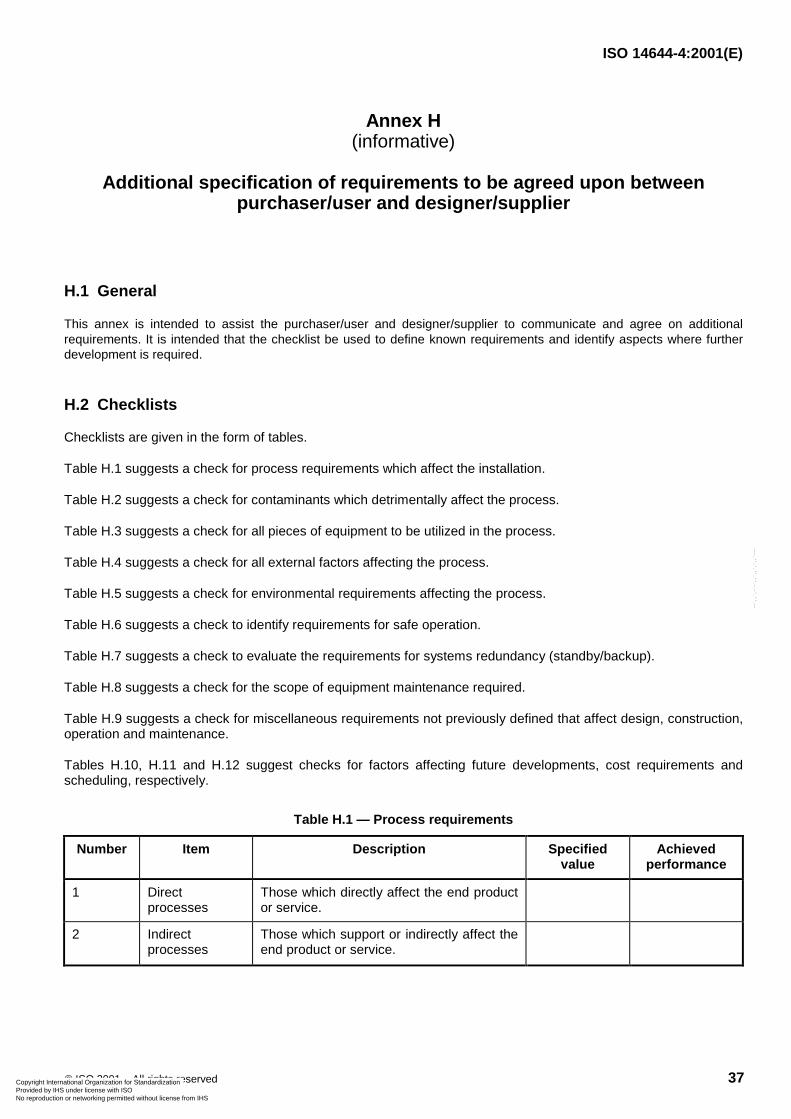
ISO 14644-4:2001(E)
© ISO 2001 – All rights reserved 37
Annex H(informative)
Additional specification of requirements to be agreed upon betweenpurchaser/user and designer/supplier
H.1 General
This annex is intended to assist the purchaser/user and designer/supplier to communicate and agree on additionalrequirements. It is intended that the checklist be used to define known requirements and identify aspects where furtherdevelopment is required.
H.2 Checklists
Checklists are given in the form of tables.
Table H.1 suggests a check for process requirements which affect the installation.
Table H.2 suggests a check for contaminants which detrimentally affect the process.
Table H.3 suggests a check for all pieces of equipment to be utilized in the process.
Table H.4 suggests a check for all external factors affecting the process.
Table H.5 suggests a check for environmental requirements affecting the process.
Table H.6 suggests a check to identify requirements for safe operation.
Table H.7 suggests a check to evaluate the requirements for systems redundancy (standby/backup).
Table H.8 suggests a check for the scope of equipment maintenance required.
Table H.9 suggests a check for miscellaneous requirements not previously defined that affect design, construction,operation and maintenance.
Tables H.10, H.11 and H.12 suggest checks for factors affecting future developments, cost requirements andscheduling, respectively.
Table H.1 — Process requirements
Number Item Description Specifiedvalue
Achievedperformance
1 Directprocesses
Those which directly affect the end productor service.
2 Indirectprocesses
Those which support or indirectly affect theend product or service.
Copyright International Organization for Standardization Provided by IHS under license with ISO
Not for ResaleNo reproduction or networking permitted without license from IHS
--`,,`,-`-`,,`,,`,`,,`---
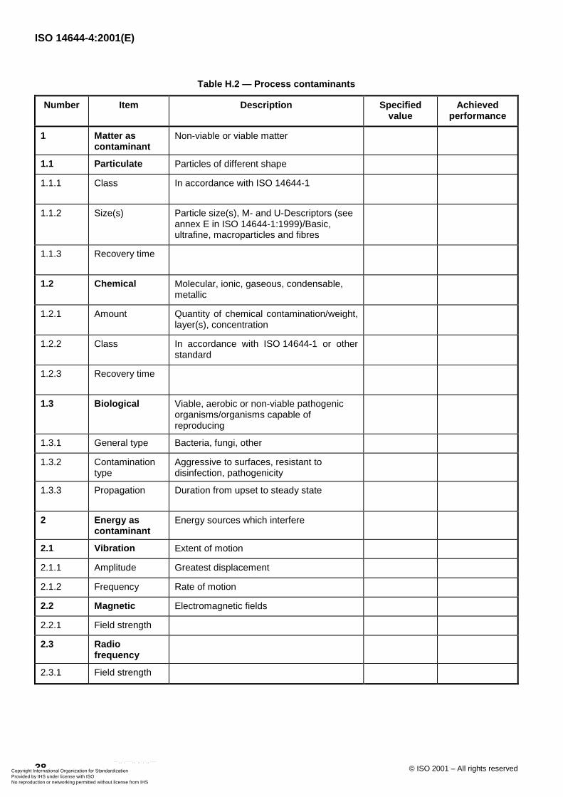
ISO 14644-4:2001(E)
38 © ISO 2001 – All rights reserved
Table H.2 — Process contaminants
Number Item Description Specifiedvalue
Achievedperformance
1 Matter ascontaminant
Non-viable or viable matter
1.1 Particulate Particles of different shape
1.1.1 Class In accordance with ISO 14644-1
1.1.2 Size(s) Particle size(s), M- and U-Descriptors (seeannex E in ISO 14644-1:1999)/Basic,ultrafine, macroparticles and fibres
1.1.3 Recovery time
1.2 Chemical Molecular, ionic, gaseous, condensable,metallic
1.2.1 Amount Quantity of chemical contamination/weight,layer(s), concentration
1.2.2 Class In accordance with ISO 14644-1 or otherstandard
1.2.3 Recovery time
1.3 Biological Viable, aerobic or non-viable pathogenicorganisms/organisms capable ofreproducing
1.3.1 General type Bacteria, fungi, other
1.3.2 Contaminationtype
Aggressive to surfaces, resistant todisinfection, pathogenicity
1.3.3 Propagation Duration from upset to steady state
2 Energy ascontaminant
Energy sources which interfere
2.1 Vibration Extent of motion
2.1.1 Amplitude Greatest displacement
2.1.2 Frequency Rate of motion
2.2 Magnetic Electromagnetic fields
2.2.1 Field strength
2.3 Radiofrequency
2.3.1 Field strength
Copyright International Organization for Standardization Provided by IHS under license with ISO
Not for ResaleNo reproduction or networking permitted without license from IHS
--`,,`,-`-`,,`,,`,`,,`---
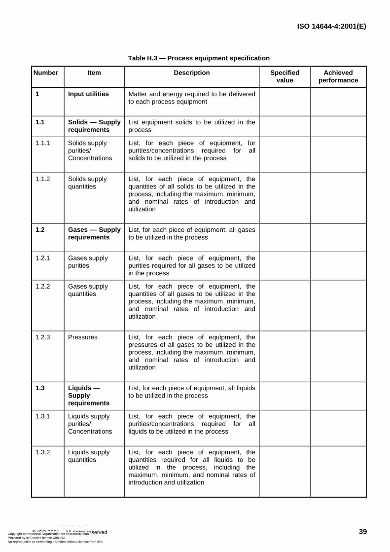
ISO 14644-4:2001(E)
© ISO 2001 – All rights reserved 39
Table H.3 — Process equipment specification
Number Item Description Specifiedvalue
Achievedperformance
1 Input utilities Matter and energy required to be deliveredto each process equipment
1.1 Solids — Supplyrequirements
List equipment solids to be utilized in theprocess
1.1.1 Solids supplypurities/Concentrations
List, for each piece of equipment, forpurities/concentrations required for allsolids to be utilized in the process
1.1.2 Solids supplyquantities
List, for each piece of equipment, thequantities of all solids to be utilized in theprocess, including the maximum, minimum,and nominal rates of introduction andutilization
1.2 Gases — Supplyrequirements
List, for each piece of equipment, all gasesto be utilized in the process
1.2.1 Gases supplypurities
List, for each piece of equipment, thepurities required for all gases to be utilizedin the process
1.2.2 Gases supplyquantities
List, for each piece of equipment, thequantities of all gases to be utilized in theprocess, including the maximum, minimum,and nominal rates of introduction andutilization
1.2.3 Pressures List, for each piece of equipment, thepressures of all gases to be utilized in theprocess, including the maximum, minimum,and nominal rates of introduction andutilization
1.3 Liquids —Supplyrequirements
List, for each piece of equipment, all liquidsto be utilized in the process
1.3.1 Liquids supplypurities/Concentrations
List, for each piece of equipment, thepurities/concentrations required for allliquids to be utilized in the process
1.3.2 Liquids supplyquantities
List, for each piece of equipment, thequantities required for all liquids to beutilized in the process, including themaximum, minimum, and nominal rates ofintroduction and utilization
Copyright International Organization for Standardization Provided by IHS under license with ISO
Not for ResaleNo reproduction or networking permitted without license from IHS
--`,,`,-`-`,,`,,`,`,,`---
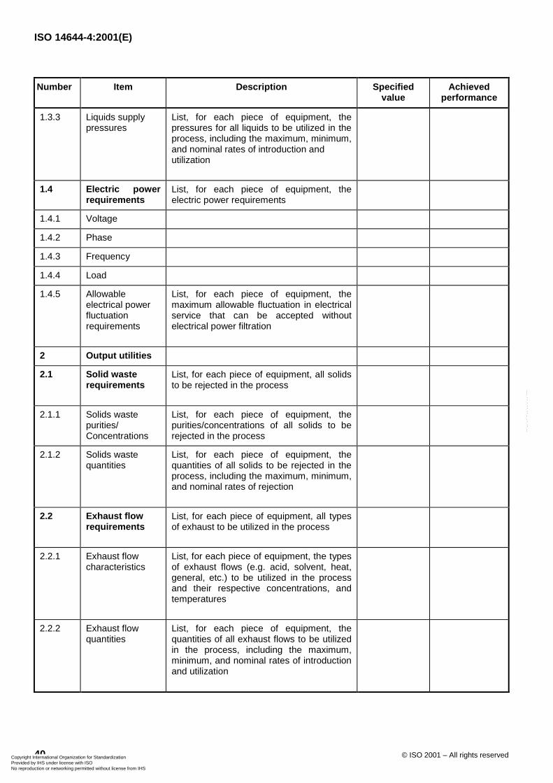
ISO 14644-4:2001(E)
40 © ISO 2001 – All rights reserved
Number Item Description Specifiedvalue
Achievedperformance
1.3.3 Liquids supplypressures
List, for each piece of equipment, thepressures for all liquids to be utilized in theprocess, including the maximum, minimum,and nominal rates of introduction andutilization
1.4 Electric powerrequirements
List, for each piece of equipment, theelectric power requirements
1.4.1 Voltage
1.4.2 Phase
1.4.3 Frequency
1.4.4 Load
1.4.5 Allowableelectrical powerfluctuationrequirements
List, for each piece of equipment, themaximum allowable fluctuation in electricalservice that can be accepted withoutelectrical power filtration
2 Output utilities
2.1 Solid wasterequirements
List, for each piece of equipment, all solidsto be rejected in the process
2.1.1 Solids wastepurities/Concentrations
List, for each piece of equipment, thepurities/concentrations of all solids to berejected in the process
2.1.2 Solids wastequantities
List, for each piece of equipment, thequantities of all solids to be rejected in theprocess, including the maximum, minimum,and nominal rates of rejection
2.2 Exhaust flowrequirements
List, for each piece of equipment, all typesof exhaust to be utilized in the process
2.2.1 Exhaust flowcharacteristics
List, for each piece of equipment, the typesof exhaust flows (e.g. acid, solvent, heat,general, etc.) to be utilized in the processand their respective concentrations, andtemperatures
2.2.2 Exhaust flowquantities
List, for each piece of equipment, thequantities of all exhaust flows to be utilizedin the process, including the maximum,minimum, and nominal rates of introductionand utilization
Copyright International Organization for Standardization Provided by IHS under license with ISO
Not for ResaleNo reproduction or networking permitted without license from IHS
--`,,`,-`-`,,`,,`,`,,`---
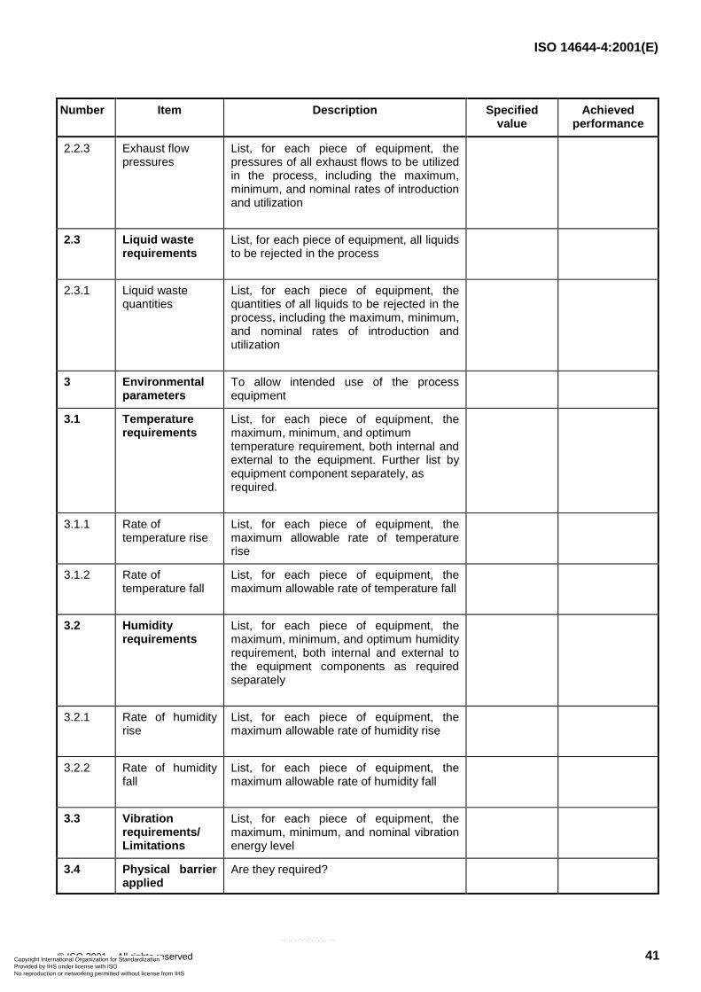
ISO 14644-4:2001(E)
© ISO 2001 – All rights reserved 41
Number Item Description Specifiedvalue
Achievedperformance
2.2.3 Exhaust flowpressures
List, for each piece of equipment, thepressures of all exhaust flows to be utilizedin the process, including the maximum,minimum, and nominal rates of introductionand utilization
2.3 Liquid wasterequirements
List, for each piece of equipment, all liquidsto be rejected in the process
2.3.1 Liquid wastequantities
List, for each piece of equipment, thequantities of all liquids to be rejected in theprocess, including the maximum, minimum,and nominal rates of introduction andutilization
3 Environmentalparameters
To allow intended use of the processequipment
3.1 Temperaturerequirements
List, for each piece of equipment, themaximum, minimum, and optimumtemperature requirement, both internal andexternal to the equipment. Further list byequipment component separately, asrequired.
3.1.1 Rate oftemperature rise
List, for each piece of equipment, themaximum allowable rate of temperaturerise
3.1.2 Rate oftemperature fall
List, for each piece of equipment, themaximum allowable rate of temperature fall
3.2 Humidityrequirements
List, for each piece of equipment, themaximum, minimum, and optimum humidityrequirement, both internal and external tothe equipment components as requiredseparately
3.2.1 Rate of humidityrise
List, for each piece of equipment, themaximum allowable rate of humidity rise
3.2.2 Rate of humidityfall
List, for each piece of equipment, themaximum allowable rate of humidity fall
3.3 Vibrationrequirements/Limitations
List, for each piece of equipment, themaximum, minimum, and nominal vibrationenergy level
3.4 Physical barrierapplied
Are they required?
Copyright International Organization for Standardization Provided by IHS under license with ISO
Not for ResaleNo reproduction or networking permitted without license from IHS
--`,,`,-`-`,,`,,`,`,,`---
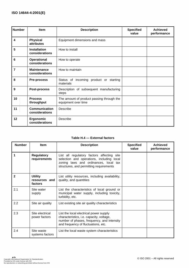
ISO 14644-4:2001(E)
42 © ISO 2001 – All rights reserved
Number Item Description Specifiedvalue
Achievedperformance
4 Physicalattributes
Equipment dimensions and mass
5 Installationconsiderations
How to install
6 Operationalconsiderations
How to operate
7 Maintenanceconsiderations
How to maintain
8 Pre-process Status of incoming product or startingmaterials
9 Post-process Description of subsequent manufacturingsteps
10 Processthroughput
The amount of product passing through theequipment over time
11 Communicationconsiderations
Describe
12 Ergonomicconsiderations
Describe
Table H.4 — External factors
Number Item Description Specifiedvalue
Achievedperformance
1 Regulatoryrequirements
List all regulatory factors affecting siteselection and operations, including localzoning laws and ordinances, local taxstructures, and permitting requirements
2 Utilityresources andfactors
List utility resources, including availability,quality, and quantities
2.1 Site watersupply
List the characteristics of local ground ormunicipal water supply, including toxicity,turbidity, etc.
2.2 Site air quality List existing site air quality characteristics
2.3 Site electricalpower factors
List the local electrical power supplycharacteristics, i.e. capacity, voltage,number of phases, frequency, and intensityand frequency of fluctuations, etc.
2.4 Site wastesystems factors
List the local waste system characteristics
Copyright International Organization for Standardization Provided by IHS under license with ISO
Not for ResaleNo reproduction or networking permitted without license from IHS
--`,,`,-`-`,,`,,`,`,,`---
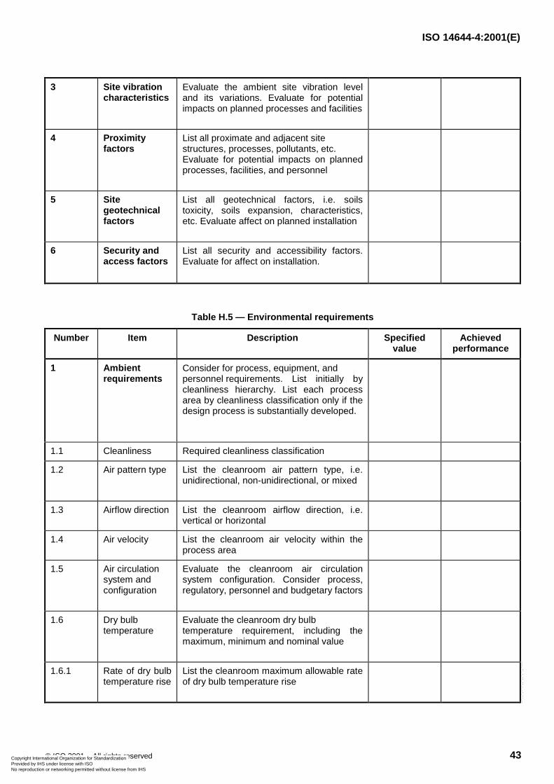
ISO 14644-4:2001(E)
© ISO 2001 – All rights reserved 43
3 Site vibrationcharacteristics
Evaluate the ambient site vibration leveland its variations. Evaluate for potentialimpacts on planned processes and facilities
4 Proximityfactors
List all proximate and adjacent sitestructures, processes, pollutants, etc.Evaluate for potential impacts on plannedprocesses, facilities, and personnel
5 Sitegeotechnicalfactors
List all geotechnical factors, i.e. soilstoxicity, soils expansion, characteristics,etc. Evaluate affect on planned installation
6 Security andaccess factors
List all security and accessibility factors.Evaluate for affect on installation.
Table H.5 — Environmental requirements
Number Item Description Specifiedvalue
Achievedperformance
1 Ambientrequirements
Consider for process, equipment, andpersonnel requirements. List initially bycleanliness hierarchy. List each processarea by cleanliness classification only if thedesign process is substantially developed.
1.1 Cleanliness Required cleanliness classification
1.2 Air pattern type List the cleanroom air pattern type, i.e.unidirectional, non-unidirectional, or mixed
1.3 Airflow direction List the cleanroom airflow direction, i.e.vertical or horizontal
1.4 Air velocity List the cleanroom air velocity within theprocess area
1.5 Air circulationsystem andconfiguration
Evaluate the cleanroom air circulationsystem configuration. Consider process,regulatory, personnel and budgetary factors
1.6 Dry bulbtemperature
Evaluate the cleanroom dry bulbtemperature requirement, including themaximum, minimum and nominal value
1.6.1 Rate of dry bulbtemperature rise
List the cleanroom maximum allowable rateof dry bulb temperature rise
Copyright International Organization for Standardization Provided by IHS under license with ISO
Not for ResaleNo reproduction or networking permitted without license from IHS
--`,,`,-`-`,,`,,`,`,,`---
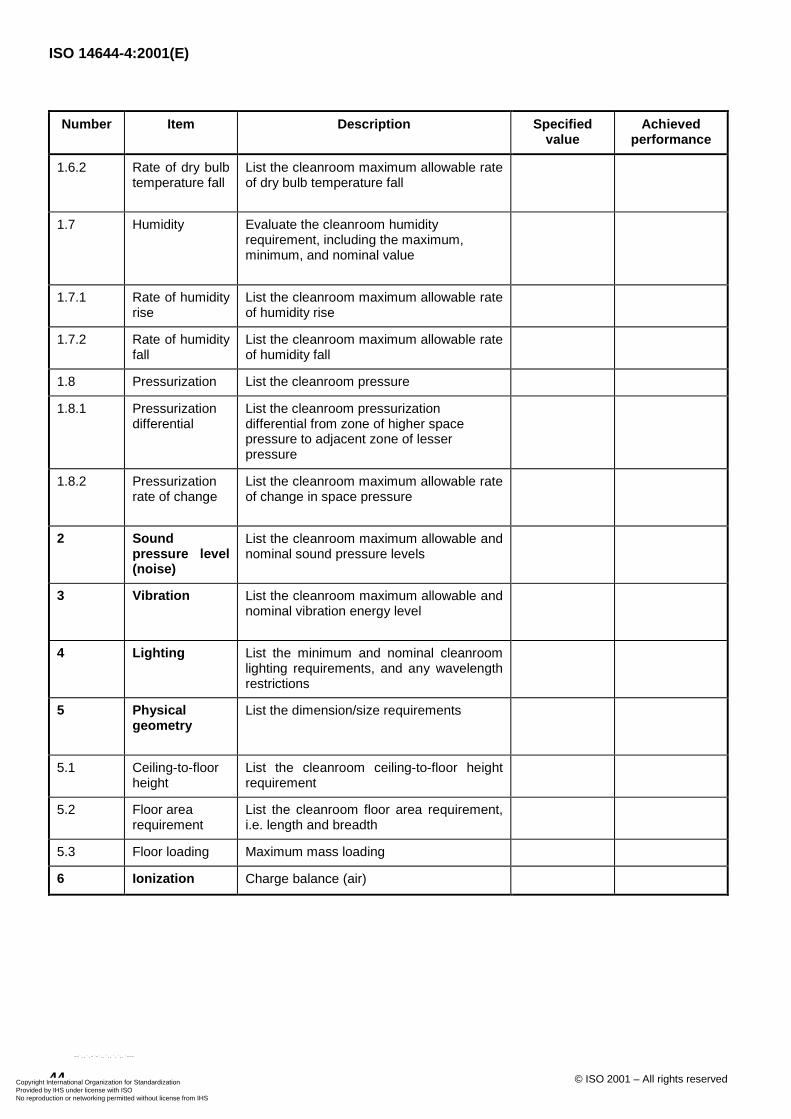
ISO 14644-4:2001(E)
44 © ISO 2001 – All rights reserved
Number Item Description Specifiedvalue
Achievedperformance
1.6.2 Rate of dry bulbtemperature fall
List the cleanroom maximum allowable rateof dry bulb temperature fall
1.7 Humidity Evaluate the cleanroom humidityrequirement, including the maximum,minimum, and nominal value
1.7.1 Rate of humidityrise
List the cleanroom maximum allowable rateof humidity rise
1.7.2 Rate of humidityfall
List the cleanroom maximum allowable rateof humidity fall
1.8 Pressurization List the cleanroom pressure
1.8.1 Pressurizationdifferential
List the cleanroom pressurizationdifferential from zone of higher spacepressure to adjacent zone of lesserpressure
1.8.2 Pressurizationrate of change
List the cleanroom maximum allowable rateof change in space pressure
2 Soundpressure level(noise)
List the cleanroom maximum allowable andnominal sound pressure levels
3 Vibration List the cleanroom maximum allowable andnominal vibration energy level
4 Lighting List the minimum and nominal cleanroomlighting requirements, and any wavelengthrestrictions
5 Physicalgeometry
List the dimension/size requirements
5.1 Ceiling-to-floorheight
List the cleanroom ceiling-to-floor heightrequirement
5.2 Floor arearequirement
List the cleanroom floor area requirement,i.e. length and breadth
5.3 Floor loading Maximum mass loading
6 Ionization Charge balance (air)
Copyright International Organization for Standardization Provided by IHS under license with ISO
Not for ResaleNo reproduction or networking permitted without license from IHS
--`,,`,-`-`,,`,,`,`,,`---
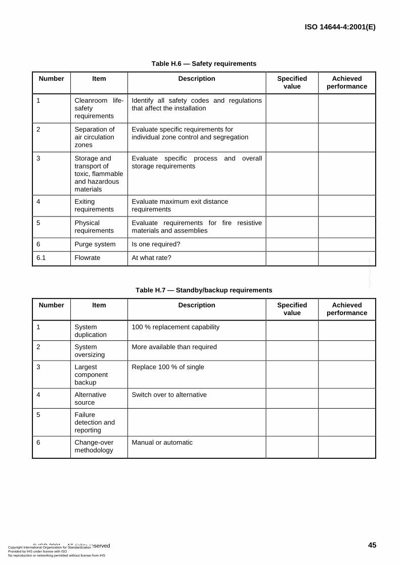
ISO 14644-4:2001(E)
© ISO 2001 – All rights reserved 45
Table H.6 — Safety requirements
Number Item Description Specifiedvalue
Achievedperformance
1 Cleanroom life-safetyrequirements
Identify all safety codes and regulationsthat affect the installation
2 Separation ofair circulationzones
Evaluate specific requirements forindividual zone control and segregation
3 Storage andtransport oftoxic, flammableand hazardousmaterials
Evaluate specific process and overallstorage requirements
4 Exitingrequirements
Evaluate maximum exit distancerequirements
5 Physicalrequirements
Evaluate requirements for fire resistivematerials and assemblies
6 Purge system Is one required?
6.1 Flowrate At what rate?
Table H.7 — Standby/backup requirements
Number Item Description Specifiedvalue
Achievedperformance
1 Systemduplication
100 % replacement capability
2 Systemoversizing
More available than required
3 Largestcomponentbackup
Replace 100 % of single
4 Alternativesource
Switch over to alternative
5 Failuredetection andreporting
6 Change-overmethodology
Manual or automatic
Copyright International Organization for Standardization Provided by IHS under license with ISO
Not for ResaleNo reproduction or networking permitted without license from IHS
--`,,`,-`-`,,`,,`,`,,`---
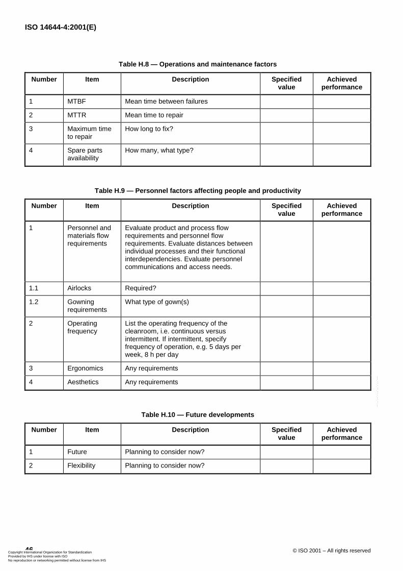
ISO 14644-4:2001(E)
46 © ISO 2001 – All rights reserved
Table H.8 — Operations and maintenance factors
Number Item Description Specifiedvalue
Achievedperformance
1 MTBF Mean time between failures
2 MTTR Mean time to repair
3 Maximum timeto repair
How long to fix?
4 Spare partsavailability
How many, what type?
Table H.9 — Personnel factors affecting people and productivity
Number Item Description Specifiedvalue
Achievedperformance
1 Personnel andmaterials flowrequirements
Evaluate product and process flowrequirements and personnel flowrequirements. Evaluate distances betweenindividual processes and their functionalinterdependencies. Evaluate personnelcommunications and access needs.
1.1 Airlocks Required?
1.2 Gowningrequirements
What type of gown(s)
2 Operatingfrequency
List the operating frequency of thecleanroom, i.e. continuous versusintermittent. If intermittent, specifyfrequency of operation, e.g. 5 days perweek, 8 h per day
3 Ergonomics Any requirements
4 Aesthetics Any requirements
Table H.10 — Future developments
Number Item Description Specifiedvalue
Achievedperformance
1 Future Planning to consider now?
2 Flexibility Planning to consider now?
Copyright International Organization for Standardization Provided by IHS under license with ISO
Not for ResaleNo reproduction or networking permitted without license from IHS
--`,,`,-`-`,,`,,`,`,,`---
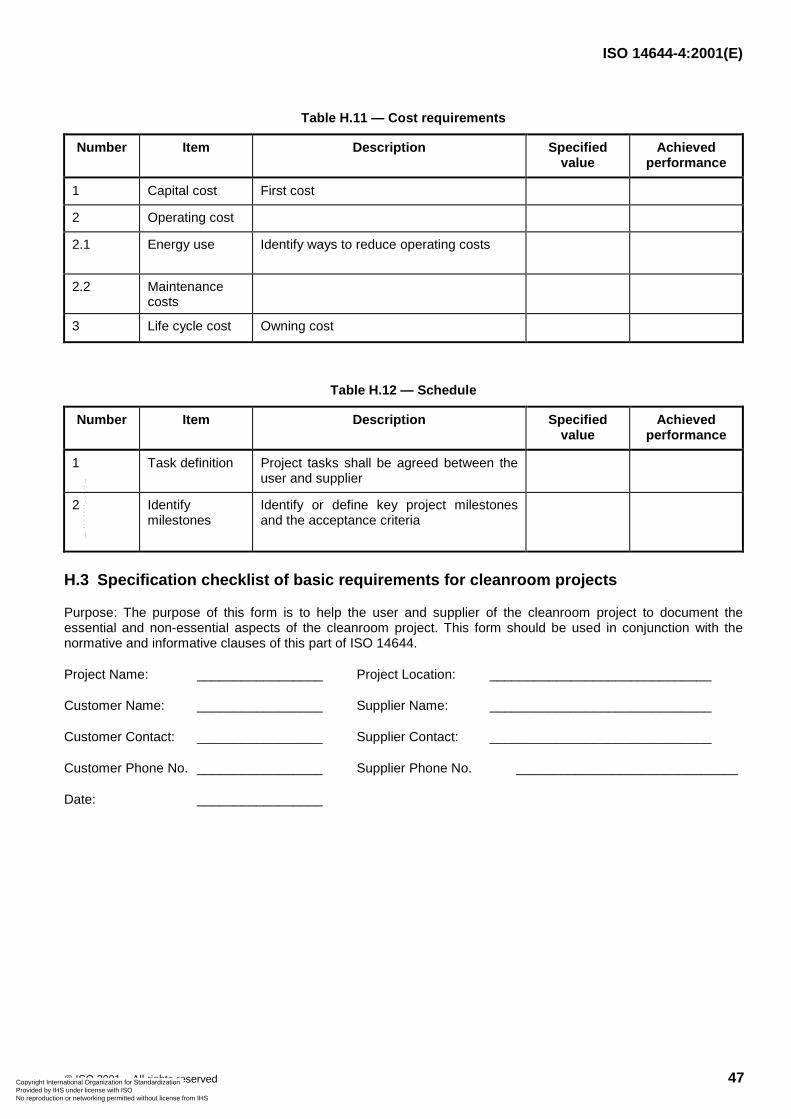
ISO 14644-4:2001(E)
© ISO 2001 – All rights reserved 47
Table H.11 — Cost requirements
Number Item Description Specifiedvalue
Achievedperformance
1 Capital cost First cost
2 Operating cost
2.1 Energy use Identify ways to reduce operating costs
2.2 Maintenancecosts
3 Life cycle cost Owning cost
Table H.12 — Schedule
Number Item Description Specifiedvalue
Achievedperformance
1 Task definition Project tasks shall be agreed between theuser and supplier
2 Identifymilestones
Identify or define key project milestonesand the acceptance criteria
H.3 Specification checklist of basic requirements for cleanroom projects
Purpose: The purpose of this form is to help the user and supplier of the cleanroom project to document theessential and non-essential aspects of the cleanroom project. This form should be used in conjunction with thenormative and informative clauses of this part of ISO 14644.
Project Name: _________________ Project Location: ______________________________
Customer Name: _________________ Supplier Name: ______________________________
Customer Contact: _________________ Supplier Contact: ______________________________
Customer Phone No. _________________ Supplier Phone No. ______________________________
Date: _________________
Copyright International Organization for Standardization Provided by IHS under license with ISO
Not for ResaleNo reproduction or networking permitted without license from IHS
--`,,`,-`-`,,`,,`,`,,`---
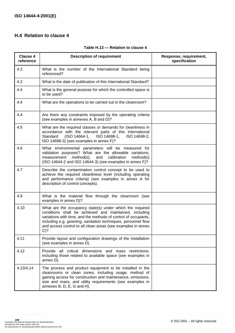
ISO 14644-4:2001(E)
48 © ISO 2001 – All rights reserved
H.4 Relation to clause 4
Table H.13 — Relation to clause 4
Clause 4reference
Description of requirement Response, requirement,specification
4.2 What is the number of the International Standard beingreferenced?
4.2 What is the date of publication of this International Standard?
4.4 What is the general purpose for which the controlled space isto be used?
4.4 What are the operations to be carried out in the cleanroom?
4.4 Are there any constraints imposed by the operating criteria(see examples in annexes A, B and D)?
4.5 What are the required classes or demands for cleanliness inaccordance with the relevant parts of this InternationalStandard (ISO 14664-1, ISO 14698-1, ISO 14698-2,ISO 14698-3) (see examples in annex F)?
4.6 What environmental parameters will be measured forvalidation purposes? What are the allowable variations,measurement method(s), and calibration method(s)(ISO 14644-2 and ISO 14644-3) (see examples in annex F)?
4.7 Describe the contamination control concept to be used toachieve the required cleanliness level (including operatingand performance criteria) (see examples in annex A fordescription of control concepts).
4.9 What is the material flow through the cleanroom (seeexamples in annex D)?
4.10 What are the occupancy state(s) under which the requiredconditions shall be achieved and maintained, includingvariations with time, and the methods of control of occupants,including e.g. gowning, sanitation techniques, personnel flowand access control to all clean areas (see examples in annexC)?
4.11 Provide layout and configuration drawings of the installation(see examples in annex D).
4.12 Provide all critical dimensions and mass restrictions,including those related to available space (see examples inannex D).
4.13/4.14 The process and product equipment to be installed in thecleanrooms or clean zones, including usage, method ofgaining access for construction and maintenance, emissions,size and mass, and utility requirements (see examples inannexes B, D, E, G and H).
Copyright International Organization for Standardization Provided by IHS under license with ISO
Not for ResaleNo reproduction or networking permitted without license from IHS
--`,,`,-`-`,,`,,`,`,,`---
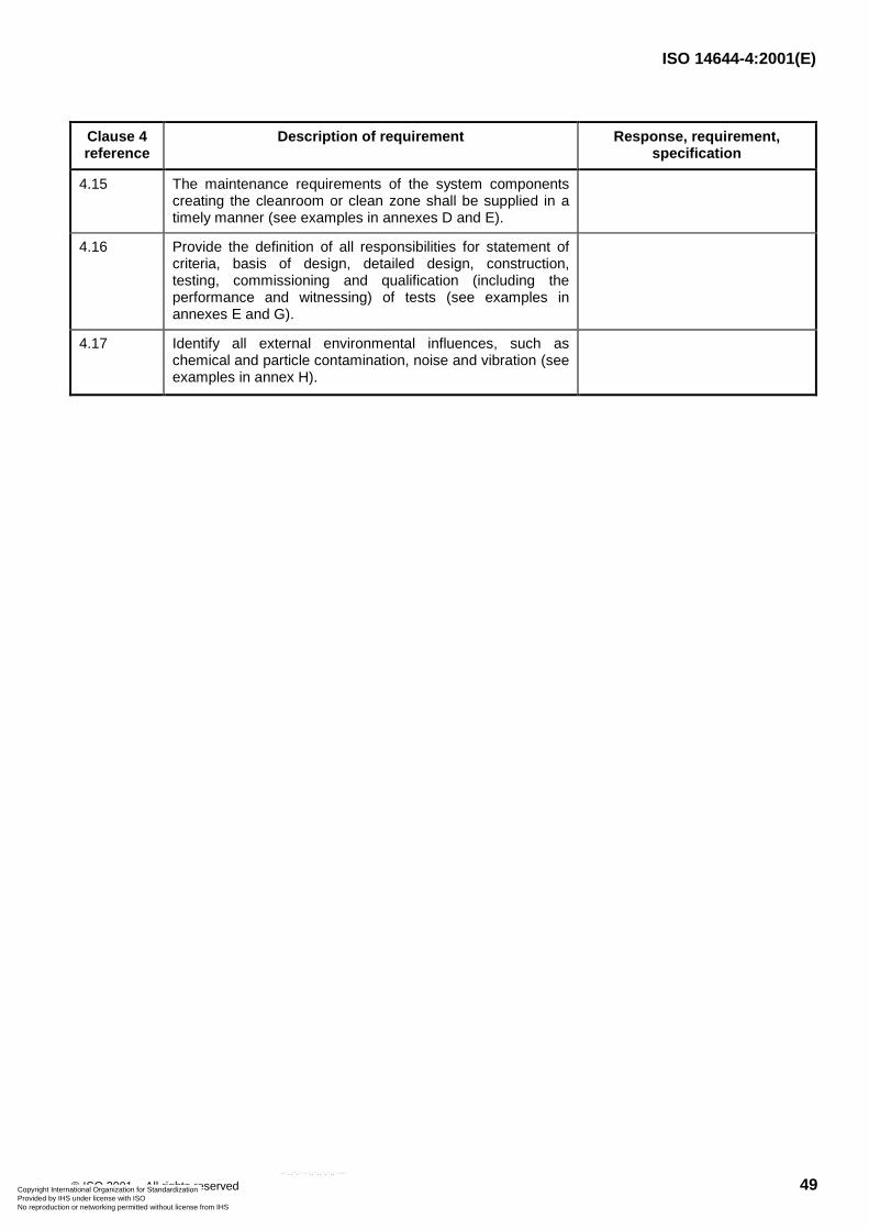
ISO 14644-4:2001(E)
© ISO 2001 – All rights reserved 49
Clause 4reference
Description of requirement Response, requirement,specification
4.15 The maintenance requirements of the system componentscreating the cleanroom or clean zone shall be supplied in atimely manner (see examples in annexes D and E).
4.16 Provide the definition of all responsibilities for statement ofcriteria, basis of design, detailed design, construction,testing, commissioning and qualification (including theperformance and witnessing) of tests (see examples inannexes E and G).
4.17 Identify all external environmental influences, such aschemical and particle contamination, noise and vibration (seeexamples in annex H).
Copyright International Organization for Standardization Provided by IHS under license with ISO
Not for ResaleNo reproduction or networking permitted without license from IHS
--`,,`,-`-`,,`,,`,`,,`---

ISO 14644-4:2001(E)
50 © ISO 2001 – All rights reserved
Bibliography
[1] ISO 1940-1:1986, Mechanical vibration — Balance quality requirements of rigid rotors —Part 1: Determination of permissible residual unbalance.
[2] ISO 3746:1995 + Technical Corrigendum 1:1995, Acoustics — Determination of sound power levels ofnoise sources using sound pressure — Survey method using an enveloping measurement surface over areflecting plane.
[3] ISO 7730:1994, Moderate thermal environments — Determination of the PMV and PPD indices andspecification of the conditions for thermal comfort.
[4] ISO 9000:2000, Quality management systems — Fundamentals and vocabulary.
[5] ISO 9001:2000, Quality management systems — Requirements.
[6] ISO 9004-1:1994, Quality management and quality system elements — Part 1: Guidelines.
[7] ISO 10816-1:1995, Mechanical vibration — Evaluation of machine vibration by measurements on non-rotating parts — Part 1: General guidelines.
[8] ISO 14001:1996, Environmental management systems — Specification with guidance for use.
[9] ISO 14004:1996, Environmental management systems — General guidelines on principles, systems andsupporting techniques.
[10] EN 779:1993, Particulate air filters for general ventilation — Requirements, testing, marking.
[11] EN 1822-1:1998, High efficiency air filters (HEPA and ULPA) — Part 1: Classification, performance testing,marking.
[12] EN 1822-2:1998, High efficiency air filters (HEPA and ULPA) — Part 2: Aerosol production, measuringequipment, particle counting statistics.
[13] EN 1822-3:1998, High efficiency air filters (HEPA and ULPA) — Part 3: Testing flat sheet filter media.
[14] EN 1822-4:1997, High efficiency air filters (HEPA and ULPA) — Part 4: Testing filter elements for leaks(scan method).
[15] EN 1822-5:1996, High efficiency air filters (HEPA and ULPA) — Part 5: Testing the efficiency of the filterelement.
[16] IEST-RP-CC001.3:1993, HEPA and ULPA filters. Mount Prospect, Illinois: Institute of EnvironmentalSciences and Technology.
[17] IEST-RP-CC007.1:1992, Testing ULPA filters. Mount Prospect, Illinois: Institute of Environmental Sciencesand Technology.
[18] IEST-RP-CC012.1:1993, Considerations in cleanrooms design. Mount Prospect, Illinois: Institute ofEnvironmental Sciences and Technology.
[19] IEST-RP-CC021.1:1995, Testing HEPA and ULPA filter media. Mount Prospect, Illinois: Institute ofEnvironmental Sciences and Technology.
[20] IEST-RP-CC024.1:1994, Measuring and reporting vibration in microelectronics facilities. Mount Prospect,Illinois: Institute of Environmental Sciences and Technology.
Copyright International Organization for Standardization Provided by IHS under license with ISO
Not for ResaleNo reproduction or networking permitted without license from IHS
--`,,`,-`-`,,`,,`,`,,`---
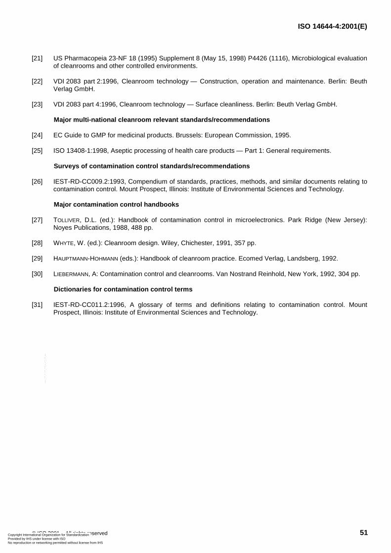
ISO 14644-4:2001(E)
© ISO 2001 – All rights reserved 51
[21] US Pharmacopeia 23-NF 18 (1995) Supplement 8 (May 15, 1998) P4426 (1116), Microbiological evaluationof cleanrooms and other controlled environments.
[22] VDI 2083 part 2:1996, Cleanroom technology — Construction, operation and maintenance. Berlin: BeuthVerlag GmbH.
[23] VDI 2083 part 4:1996, Cleanroom technology — Surface cleanliness. Berlin: Beuth Verlag GmbH.
Major multi-national cleanroom relevant standards/recommendations
[24] EC Guide to GMP for medicinal products. Brussels: European Commission, 1995.
[25] ISO 13408-1:1998, Aseptic processing of health care products — Part 1: General requirements.
Surveys of contamination control standards/recommendations
[26] IEST-RD-CC009.2:1993, Compendium of standards, practices, methods, and similar documents relating tocontamination control. Mount Prospect, Illinois: Institute of Environmental Sciences and Technology.
Major contamination control handbooks
[27] TOLLIVER, D.L. (ed.): Handbook of contamination control in microelectronics. Park Ridge (New Jersey):Noyes Publications, 1988, 488 pp.
[28] WHYTE, W. (ed.): Cleanroom design. Wiley, Chichester, 1991, 357 pp.
[29] HAUPTMANN-HOHMANN (eds.): Handbook of cleanroom practice. Ecomed Verlag, Landsberg, 1992.
[30] LIEBERMANN, A: Contamination control and cleanrooms. Van Nostrand Reinhold, New York, 1992, 304 pp.
Dictionaries for contamination control terms
[31] IEST-RD-CC011.2:1996, A glossary of terms and definitions relating to contamination control. MountProspect, Illinois: Institute of Environmental Sciences and Technology.
Copyright International Organization for Standardization Provided by IHS under license with ISO
Not for ResaleNo reproduction or networking permitted without license from IHS
--`,,`,-`-`,,`,,`,`,,`---

ISO 14644-4:2001(E)
ICS 13.040.30Price based on 51 pages
© ISO 2001 – All rights reserved
Copyright International Organization for Standardization Provided by IHS under license with ISO
Not for ResaleNo reproduction or networking permitted without license from IHS
--`,,`,-`-`,,`,,`,`,,`---