Embed Size (px)
Citation preview

1
Formatted: Font: (Default) +Headings (Calibri Light),
14 pt
ISLAMIC UNIVERSITY OF TECHNOLOGY, IUT
ORGANISATION OF THE ISLAMIC COOPERATION, OIC
HIGHER DIPLOMA IN ELECTRICAL AND ELECTRONICS
ENGINEERING
ATTENDANCE SYSTEM USING ARDUINO
PRESENTED BY:
Nchouwat N.I. Moubarak: 122318
Abdoul Kadiri Lawane: 142323
Nadoukou Idriss Adamou: 142324
Abdourahimou Saidou: 142326
SUPERVISED BY:
Dr. RAKIBUL HASAN SAGOR
(ASSISTANT PROFESSOR, EEE DEPT)
Department of Electrical and Electronic Engineering (EEE)
November -2017
2
Formatted: Font: (Default) +Headings (Calibri Light),
14 pt
Certification:
This is to certify that this project report entitled “ATTENDANCE SYSTEM USING
ARDUINO”
Is a true work of Nchouwat N.I. Moubarak (122318) , Abdoul kadiri lawane (142323),Nadoukou
Idriss Adamou(142324), and Abdourahimou Saidou (142326),who successfully carried out the
work project under the supervision of Dr. RAKIBUL HASAN SAGOR ,EEE Department, Islamic
university of Technology(IUT).This project counts as our final year project which put an end to
our three years program as HDEE (Higher Diploma in electrical and electronics engineering) at
the Islamic University of Technology (IUT) Dhaka, Bangladesh.
Author:
Nchouwat N.I. Moubarak: 122318
Abdoul Kadiri Lawane: 142323
Nadoukou Idriss Adamou: 142324
Abdourahimou Saidou: 142326
Date:
Supervisor:
Signature:
Name: Rakibul Hassan Sagor
Date:
Head of department
Signature
Name: Prof. Dr. Ashraful Hoque
Date:
Department of Electrical and Electronic Engineering (EEE)
Islamic University of Technology (IUT)

3
Formatted: Font: (Default) +Headings (Calibri Light),
14 pt
Abstract
Due to the rapid growing number of students in the ISLAMIC UNIVERSITY OF TECHNOLOGY
(IUT) we as electrical and electronics engineering student thought it better to design a student
attendance based system that could effectively manage the attendance of students . Attendance is
marked after the student have enrolled. For student enrollment, an optical fingerprint sensor is
used. Once the fingerprints are taken the name and the student ID of the student is assigned to the
fingerprint which is then stored in the internal memory of the Arduino Uno. Fingerprints are
considered to be the best and fastest method for biometric identification. They are secure to use,
unique for every person and does not change in one’s lifetime. It was our responsibility to
implement the fingerprint identification system for faster taking of attendance. This system was
implemented in Arduino Uno board.

4
Formatted: Font: (Default) +Headings (Calibri Light),
14 pt
Acknowledgements
We thank the most merciful Allah (SWT), by whose grace and blessing has spiritually help and
give us strength to accomplish and complete this project. We would like to extent our sincerest
gratitude and thanks to our esteemed supervisor Dr Rakibul Hasan Sagor Assistant professor,
Department of Electrical and Electronics Engineering. He is not only helpful supervisor with deep
vision but also most importantly a kind person. We sincerely think him for his guidance and
encouragement. His trust and support inspired us in the most important moment of making right
decisions and it was a great pleasure for us to work with him. We would like to thanks our beloved
parents, who taught us the value of hard work by their own example. Lastly we would also like to
thanks all those who assisted us during this long journey of work.

5
Formatted: Font: (Default) +Headings (Calibri Light),
14 pt
Table of contents
Certification…………………………………………………………………………………..2
Abstract………………………………………………………………………………….…...3
Acknowledgement…………………………………………………………………………...4
Table of contents……………………………………………………………………….…5-7
List of figures……………………………………………………………...……………..….8
Introduction………………………………………………………………………………….9
Chapter 1: Literature Review………………………………………………………….….10
1.1 Sensors.......................................................................................................................10
1.1.1. Criteria to be considered in choosing a Sensor…………………………………..10
1.1.2. Classification of Sensors……………………………………………………....…..10
1.1.3 Classification based on property…………………………………………….…....11
1.1.4 Classification based on Application…………………………………………..….11
1.1.5 Classification based on power or energy supply requirement of the sensor..12
1.1.6 Current an future applications………………………………………….......…...12
1.2 Case study: fingerprint sensor………………………………………………...…12
1.2.1 Optical Scanning……………………………………………………………….…12
1.2.2 Capacitive Scanning………………………………………………………..….…13
1.2.3 Ultra-Sonic Scanner…………………………………………………….…….….13
1.3 Display devices…………………………………………………………………....14
1.3.1 Segment displays………………………………………………………………....14
1.3.2 Underlying technologies……………………………………………………........15
1.3.3 Full area two dimensions………………………………………………….…..…15
1.4 Applications……………………………………………………………..……..…15
1.4.1 Two dimensions…………………………………………….………………….....15
1.4.2 Three dimensions……………………………………………………………....…15
1.5 Microcontrollers………………………………………………………………….15
1.5.1 Types of Microcontrollers………………………………………………….……16
6
Formatted: Font: (Default) +Headings (Calibri Light),
14 pt
1.5.2 Applications for Microcontrollers……………………………………....…….17
Chapter 2: COMPONENTS USED…………………………………………………...18
2.1 Arduino ………………………………………………………………….………….18
2.1.1 Definition……………………………………………………………………….....18
2.1.2 Why Arduino Boards……………………………………………….…….………19
2.1.3 Some Families of Arduino………………………………………………………..19
2.1.3.4 Arduino Uno………………………………………………………………….…20
Chapter 3: Fingerprint sensors…………………………………………………..……22
3.1 Definition………………………………………………………………………...….22
3.2 Types of Fingerprint………………………………………………………….…....22
3.2.1 Capacitive sensors………………………………………………………………..22
3.2.2 Optical Sensors……………………………………………………………….….23
3.2.3 Capacitive……………………………………………………………………..…..23
3.2.4 Optical Sensors………………………………………………………………....…23
Chapter 4: LCD……………………………………………………………………..….24
4.1 Definition………………………………………………………………………..…..24
4.2 Specification…………………………………………………………………….…..25
Chapter 5: The Variable Resistor and jumping wire………………………...……...26
5.1 variable resistor………………………………………………………………….…26
5.2 Jumping wire………………………………………………………………….……26
Chapter 6: WORK DONE…………………………………………………..…….…..27
6.1 Hardware…………………………………………………………………….……..27

7
Formatted: Font: (Default) +Headings (Calibri Light),
14 pt
6.2 Software…………………………………………………………………..………..28
6.3 Working principle……………………………………………………………..…..29
6.4 Results obtained……………………………………………………...….………...29
6.5 Problems faced………………………………………………………….……..…..29
6.6 Attempted solutions …………………………………………………………..…..30
6.7 Conclusion…………………………………………………………………….…..30
Reference………………………………………………………………………………30
Appendix………………………………………………………………………..….31-44

8
Formatted: Font: (Default) +Headings (Calibri Light),
14 pt
List of Figures
Figure 0 : Optical Sensor…………………………………………………………………..14
Figure 1 : Capacitive Sensor………………………………………………………………14
Figure 2 :Arduino Board…………………………………………………………………..20
Figure 3 : Fingerprint Sensor……………………………………………………………...25
Figure 4 :Liquid Crystal Display………………………………………………………….28
Figure 5 :Variable Resistor………………………………………………………………..30
Figure 6:Wires and Breadboards…………………………………………………………31
Figure 7:Connection Layout………………………………………………………………33

9
Formatted: Font: (Default) +Headings (Calibri Light),
14 pt
Introduction
The rapid growing number of students in schools and university milieus nowadays
necessitate efficient class management systems. Traditional and existing attendance management
systems are time wasting and non-reliable so the introduction of a smart system with the use of
fingerprint would help remedy these problems
The smart attendance system is based on the use of biometric data including; signals
generated from the face, eye, voice, fingerprints etc. These signals are specific and unique for each
and every body. The data is captured, nurtured and processed to produce digital information that
can then be used to identify the particular student.
A sensor is used to converts the physical information just like these signals, into an
electrical signal, voltage or current. The electrical signal is then sampled and quantized to yield
digital signal or code that is then utilized within a code loaded in a microcontroller which then
displays the information on an lcd. Our project uses a finger print sensor to get unique and specific
information from student.

10
Formatted: Font: (Default) +Headings (Calibri Light),
14 pt
Chapter 1
Literature Review
To obtain a biometric information from someone, biometric data from that person need to
be capture, by a sensor. Then this data has to be nurtured, by a microcontroller like Arduino then
the final information has to be displayed to be visible on a display board like an LCD.
The literature of the main parts of our project are detail beneath:
1.1. Sensors
They are sophisticated devices that are frequently used to detect and respond to electrical
or optical signals. A sensor converts the physical parameter (for example: temperature, blood
pressure, humidity, speed, etc.) Into a signal which can be measured electrically.
Explanation of an example for temperature. The mercury in the glass thermometer expands
and contracts the liquid to convert the measured temperature which can be read by a viewer on the
calibrated glass tube.
1.1.1 Criteria for choosing a Sensor
There are certain features which have to be considered when we choose a sensor. They are as
given below:
Accuracy: The ability of the sensor to measure a given parameter with high precision and
fidelity
Range-Measurement limit of sensor2.Environmental condition-usually has limits for
temperature/ humidity
Calibration - Essential for most of the measuring devices as the readings changes with time
Resolution - Smallest increment detected by the sensor
Cost
Repeatability - The reading that varies is repeatedly measured under the same environment
Sensors can be classified based on the following criteria:
Primary Input quantity ( Measurand )

11
Formatted: Font: (Default) +Headings (Calibri Light),
14 pt
Transduction principles (Using physical and chemical effects)
Material and Technology
Property
Application
Transduction principle is the fundamental criteria which are followed for an efficient approach.
Usually, material and technology criteria are chosen by the development engineering group.
1.1.3 Classification based on property
Temperature - Thermistors, thermocouples, RTD’s, IC and many more.
Pressure - Fibre optic, vacuum, elastic liquid based manometers, LVDT, electronic.
Flow - Electromagnetic, differential pressure, positional displacement, thermal mass, etc.
Level sensor-Differential pressure, ultrasonic radio frequency, radar, thermal
displacement, etc.
Proximity and displacement - LVDT, photoelectric, capacitive, magnetic, ultrasonic.
Biosensors - Resonant mirror, electrochemical, surface Plasmon resonance, Light
addressable potentio-metric.
Image - Charge coupled devices, CMOS
Gas and chemical - Semiconductor, Infrared, Conductance, Electrochemical.
Acceleration - Gyroscopes, Accelerometers.
Others - Moisture, humidity sensor, Speed sensor, mass, Tilt sensor, force, viscosity.
Surface Plasmon resonance and Light addressable potentio-metric from the Bio-sensors group are
the new optical technology based sensors. CMOS Image sensors have low resolution as compared
to charge coupled devices. CMOS has the advantages of small size, cheap, less power consumption
and hence are better substitutes for Charge coupled devices. Accelerometers are independently
grouped because of their vital role in future applications like aircraft, automobiles, etc and in fields
of videogames, toys, etc. Magnetometers are those sensors which measure magnetic flux intensity
B (in units of Tesla or As/m2).
Industrial process control, measurement and automation
12
Formatted: Font: (Default) +Headings (Calibri Light),
14 pt
Non-industrial use – Aircraft, Medical products, Automobiles, Consumer electronics, other
type of sensors.
1.1.5 Classification based on power or energy supply requirement of the sensors:
Active Sensor - Sensors that require power supply are called as Active Sensors. Example:
LiDAR (Light detection and ranging), photoconductive cell.
Passive Sensor - Sensors that do not require power supply are called as Passive Sensors.
Example: Radiometers, film photography.
1.1.6 Current and future applications:
Biosensors - These are based on the electrochemical technology. They are used for food
testing, medical care device, water testing, and biological warfare agent detection.
Image Sensors - These are based on the CMOS technology. They are used in consumer
electronics, biometrics, traffic and security surveillance and PC imaging.
1.2 Case study: fingerprint sensor
These is a device that can convert the fingerprints of people into particular codes.
The finger print can get information in three ways;
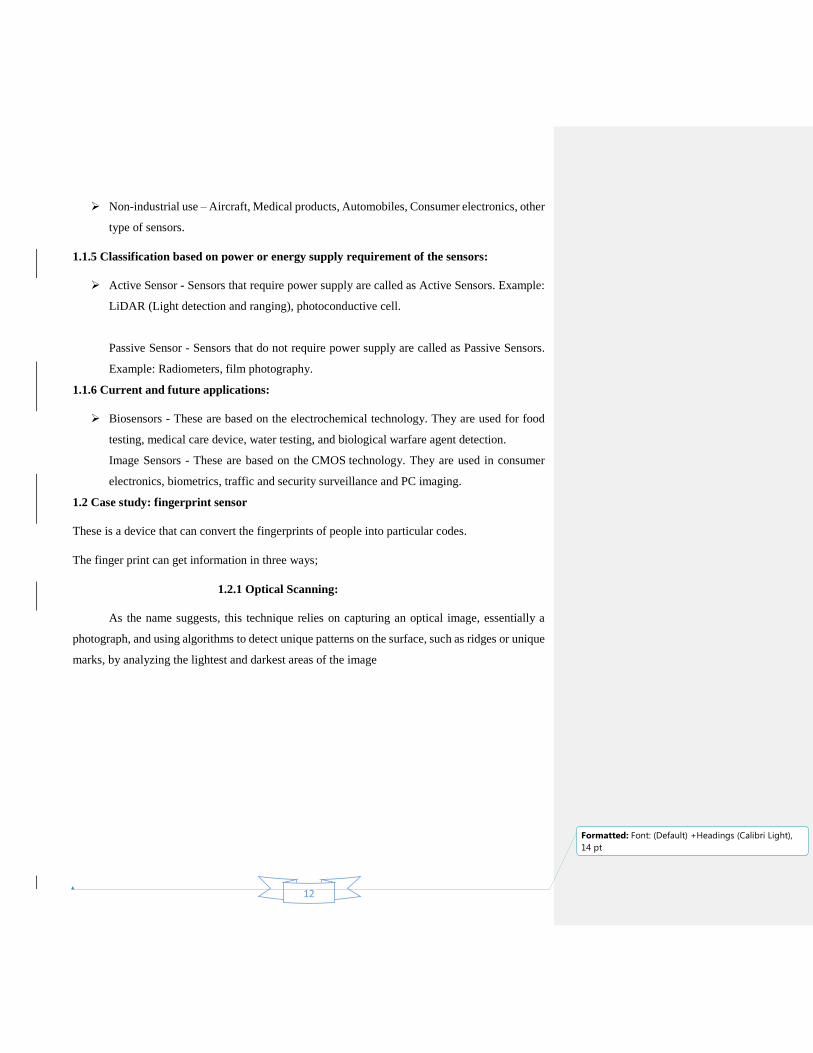
1.2.1 Optical Scanning:
As the name suggests, this technique relies on capturing an optical image, essentially a
photograph, and using algorithms to detect unique patterns on the surface, such as ridges or unique
marks, by analyzing the lightest and darkest areas of the image
13
Formatted: Font: (Default) +Headings (Calibri Light),
14 pt
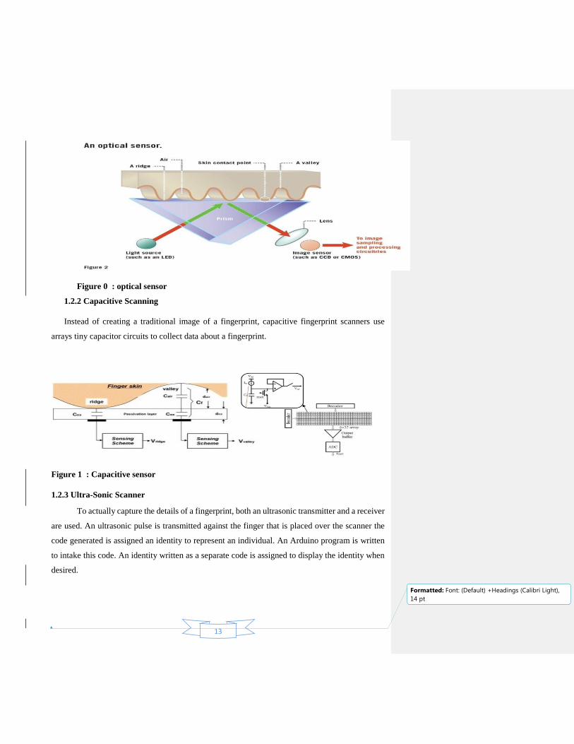
Figure 0 : optical sensor
1.2.2 Capacitive Scanning
Instead of creating a traditional image of a fingerprint, capacitive fingerprint scanners use
arrays tiny capacitor circuits to collect data about a fingerprint.
Figure 1 : Capacitive sensor
1.2.3 Ultra-Sonic Scanner
To actually capture the details of a fingerprint, both an ultrasonic transmitter and a receiver
are used. An ultrasonic pulse is transmitted against the finger that is placed over the scanner the
code generated is assigned an identity to represent an individual. An Arduino program is written
to intake this code. An identity written as a separate code is assigned to display the identity when
desired.

14
Formatted: Font: (Default) +Headings (Calibri Light),
14 pt
1.3 Display devices
A display device is an output device for presentation of information in visual or tactile form (the
latter used for example in tactile electronic displays for blind people). When the input information
is supplied has an electrical signal, the display is called an electronic display.
Electrically operated display devices have developed from electromechanical systems for
display of text, up to all-electronic devices capable of full-motion 3D color graphic displays.
Electromagnetic devices, using a solenoid coil to control a visible flag or flap, were the earliest
type, and were used for text displays such as stock market prices and arrival/departure display
times. The cathode ray tube was the workhorse of text and video display technology for several
decades until being displaced by plasma, liquid crystal (LCD) and solid-state devices such
as LEDs and OLEDs. With the advent of microprocessors and microelectronic devices, many
more individual picture elements ("pixels") could be incorporated into one display device,
allowing graphic displays and video. Displays include
Underlying technologies
Segment displays
Full area two dimensions displays
Three dimension types
Mechanical types
1.3.1 Segment displays
Some displays can show only digits or alphanumeric characters. They are called segment
displays, because they are composed of several segments that switch on and off to give appearance
of desired glyph. The segments are usually single LEDs or liquid crystals. They are mostly used
in digital watches and pocket calculators. There are several types:
The common segment displays shown side by side: 7-segment, 9-segment, 14-
segment and 16-segmentdisplays.
Seven-segment display (most common, digits only)
Fourteen-segment display
Sixteen-segment display

15
Formatted: Font: (Default) +Headings (Calibri Light),
14 pt
1.3.2 Underlying technologies
Incandescent filaments
Cum fluorescent
Cold cathode gas discharge
Light-emitting diode (LED)
Liquid crystal display (LCD)
Physical vane with electromagnetic activation
1.2.3 Full area two dimensions
Two-dimensional displays that cover a full area (usually a rectangle) are also called video
displays, since it is the main modality of presenting video.
1.4 Applications
1.4.1 Two dimensions
Television sets
Computer monitors
Head-mounted display
Broadcast reference monitor
Medical monitors
1.4.2 Three dimensions
Swept-volume display
Varifocal mirror display
Emissive volume display
Laser display
Holographic display
Light field displays
1.5 Microcontrollers
16
Formatted: Font: (Default) +Headings (Calibri Light),
14 pt
A microcontroller is a self-contained system with peripherals, memory and a processor that
be used as an embedded system. Most programmable microcontrollers that are used today are
embedded in other consumer products or machinery including phones, peripherals, automobiles
and household appliances for computer systems. Due to that, another name for a microcontroller
is "embedded controller." Some embedded systems are more sophisticated, while others have
minimal requirements for memory and programming length and a low software complexity. Input
and output devices include solenoids, LCD displays, relays, switches and sensors for data like
humidity, temperature or light level, amongst others.
1.5.1 Types of Microcontrollers
There are several different kinds of programmable microcontrollers at Future Electronics.
We stock many of the most common types categorized by several parameters including Bits, Flash
size, and RAM size, number of input/output lines, packaging type, supply voltage and speed. Our
parametric filters will allow you to refine your search results according to the required
specifications.
Programmable microcontrollers contain general purpose input/output pins. The number of
these pins varies depending on the microcontroller. They can be configured to an input or an output
state by software. When configured to an input state, these pins can be used to read external signals
or sensors. When they are configured to the output state, they can drive external devices like LED
displays and motors.
There is a wide range of programmable microcontrollers, including pic, low power, LCD,
USB and wireless microcontrollers from several manufacturers. Once you decide if you need 8 bit,
16 bit general purpose, 16 bit digital signal controllers or 32 bit microcontrollers, you will be able
to choose from their technical attributes and your search results will be narrowed to match your
specific microcontroller application needs. Microcontrollers are produced based on the number of
Bits required. The sizes of microcontrollers include:
8 bit Microcontrollers
16 bit Digital Signal Controllers (DSC)
16 bit General Purpose Microcontrollers
32 bit Microcontrollers

17
Formatted: Font: (Default) +Headings (Calibri Light),
14 pt
One a microcontroller size is made, it can still be narrowed down by various attributes: by
RAM size, Flash size, number of input lines, speed and supply voltage to name a few. The finding
of the right LCD, low power, USB, wireless or pic microcontrollers using these filters is possible.
1.5.2 Applications for Microcontrollers:
Programmable microcontrollers are designed to be used for embedded applications, unlike
microprocessors that can be found in PCs. Microcontrollers are used in automatically controlled
devices including power tools, toys, implantable medical devices, office machines, engine control
systems, appliances, remote controls and other types of embedded systems.
Chapter 2
COMPONENTS USED
2.1 Arduino
2.1.1 Definition:
Arduino is a tool for making computers that can sense and control more of the physical
world than your desktop computer. It's an open-source physical computing platform based on a
simple microcontroller board, and a development environment for writing software for the board.
Arduino can be used to develop interactive objects, taking inputs from a variety of switches or
sensors, and controlling a variety of lights, motors, and other physical outputs. Arduino projects
can be stand-alone, or they can be communicated with software running on your computer. The
boards can be assembled by hand or purchased preassembled; the open-source IDE can be
downloaded for free. The Arduino programming language is an implementation of Wiring, a
similar physical computing platform, which is based on the Processing multimedia programming
environment.

18
Formatted: Font: (Default) +Headings (Calibri Light),
14 pt
Figure 2: Arduino uno board
2.1.2 Why Arduino Boards?
Arduino board has been used for making different engineering projects and different
applications. The Arduino software is very simple to use for beginners, yet flexible adequate for
advanced users. It runs windows, Linux and Mac. Teachers and students in the schools utilize it to
design low cost scientific instruments to verify the principles of physics and chemistry. There are
numerous other microcontroller platforms obtainable for physical computing. The Net media’s
BX-24, Parallax Basic Stamp, MIT’s Handy board, Phidget and many others present related
functionality.
Arduino also makes simpler the working process of microcontroller, but it gives some
advantages over other systems for teachers, students and beginners.
Inexpensive
Cross-platform
Simple, clear programming environment
Open source and extensible software
Open source and extensible hardware
19
Formatted: Font: (Default) +Headings (Calibri Light),
14 pt
2.1.3 Some Families Of Arduino
1 - Arduino Uno
The Uno is a huge option for your initial Arduino. It consists of 14-digital I/O pins, where
6-pins can be used as PWM (pulse width modulation outputs), 6-analog inputs, a reset button, a
power jack, a USB connection and more. It includes everything required to hold up the
microcontroller; simply attach it to a PC with the help of a USB cable and give the supply to get
started with a AC-to-DC adapter or battery.
2 - Arduino Leonardo
The first development board of an Arduino is the Leonardo board. This board uses one
microcontroller along with the USB. That means, it can be very simple and cheap also. Because
this board handles USB directly, program libraries are obtainable which let the Arduino board to
follow a keyboard of the computer, mouse, etc.
3 - Arduino Lily Pad
The Lily Pad Arduino board is a wearable e-textile technology expanded by Leah “
Buechley”and considerately designed by “Leah and Spark Fun”. Each board was imaginatively
designed with huge connecting pads & a smooth back to let them to be sewn into clothing using
conductive thread. This Arduino also comprises of I/O, power, and also sensor boards which are
built especially for e-textiles. These are even washable!
4 - Arduino Mega
The Arduino Mega is similar to the UNO’s big brother. It includes lots of digital I/O pins
(from that, 14-pins can be used as PWM output), 6-analog inputs, a reset button, a power jack, a
USB connection and a reset button. It includes everything required to hold up the microcontroller;
simply attach it to a PC with the help of a USB cable and give the supply to get started with a AC-
to-DC adapter or battery. The huge number of pins make this Arduino board very helpful for
designing the projects that need a bunch of digital input or output like lots buttons
5 - Arduino Nano

20
Formatted: Font: (Default) +Headings (Calibri Light),
14 pt
The Arduino Nano Is A Small, Complete, And Breadboard-Friendly Board Based On The
Atmega328 (Arduino Nano 3.0) Or Atmega168 (Arduino Nano 2.X). It Has More Or Less The
Same Functionality Of The Arduino Duemilanove, But In A Different Package. It Lacks Only A
Dc Power Jack, And Works With A Mini-B USB Cable Instead Of A Standard One. The Nano
Was Designed And Is Being Produced By Gravitech.
2.1.3.4 Arduino Uno
Arduino Uno is a microcontroller board based on the atmega328 (datasheet)
It has 14 digital input/output pins (of which 6 can be used as PWM outputs)
6 analog inputs, a 16 MHz ceramic resonator, a USB connection, a power jack, an ICSP
header, and a reset button
It contains everything needed to support the microcontroller
It is simply connected to a computer with a USB cable or powered using an AC-to-DC
adapter or battery to get started.
Figure 2 : Arduino uno board
Microcontroller ATmega328
Operating Voltage 5V
Supply Voltage (recommended) 7-12V
Maximum supply voltage (not recommended) 20V
Digital I/O Pins 14 (of which 6 provide PWM output)
Analog Input Pins 6
DC Current per I/O Pin 40 mA
DC Current for 3.3V Pin 50 mA
Flash Memory 32 KB (ATmega328) of which 0.5 KB used by bootloader

21
Formatted: Font: (Default) +Headings (Calibri Light),
14 pt
SRAM 2 KB (ATmega328)
EEPROM 1 KB (ATmega328)
Clock Speed 16 MHz
Chapter 3
Fingerprint sensors
3.1 Definition
Fingerprint is an impression left by the friction ridges of a human finger. So a
fingerprint sensor is an electronic device used to capture a digital image of the fingerprint pattern.
The captured image is called a live scan. This live scan is digitally processed to create a biometric
template (a collection of extracted features) which is stored and used for matching.
Many technologies have been used including optical, capacitive, RF, thermal, piezo
resistive, ultrasonic, piezoelectric.
Figure 3: fingerprint sensor

22
Formatted: Font: (Default) +Headings (Calibri Light),
14 pt
3.2 Types of Fingerprint
There are many types of Fingerprint Sensor which include optical, Ultrasonic capacitance
which are sub-divided into passive and active capacitance fingerprints. But the most commonly
used are Optical Fingerprint sensors and capacitive fingerprint sensors.
3.2.1 Capacitive sensors
3.2.2 Optical Sensors
Optical sensors use arrays of photodiode or phototransistor detectors to convert the energy
in light incident on the detector into electrical charge. The sensor package usually includes a light-
emitting-diode (LED) to illuminate the finger with optical sensors, the finger is placed on a plate
and illuminated by LED light sources. Through a prism and a system of lenses, the image is
projected on a CMOS image sensor. Using frame grabber techniques, the image is stored and ready
for analysis.
3.2.3 Capacitive
Greater miniaturization
Newer technology
Can be embedded into small devices
Prone to dirt etc since finger touches silicon, and finally relatively cheap
Larger sensing area since manufacturing, large pure silicon chips is expensive, more robust.
Longer life, more expensive, better image quality and higher resolution. For our project we used
the fingerprint Recognition Module FPM10A Optical fingerprint which has the following
specificities;
High quality
100% Brand new

23
Formatted: Font: (Default) +Headings (Calibri Light),
14 pt
Fast delivery
PayPal accept
Chapter 4
LCD
4.1 Definition
LCD (liquid crystal display) is the technology used for displays in notebook and other
smaller computers. Like light-emitting diode (LED) and gas-plasma technologies, LCDs allow
displays to be much thinner than cathode ray tube (CRT) technology. LCDs consume much less
power than LED and gas-display displays because they work on the principle of blocking light
rather than emitting it.
Pin
No Function Name

24
Formatted: Font: (Default) +Headings (Calibri Light),
14 pt
1 Ground (0V) Ground
2 Supply voltage; 5V (4.7V – 5.3V) Vcc
3 Contrast adjustment; through a variable resistor VEE
4 Selects command register when low; and data register when high Register Select
5 Low to write to the register; High to read from the register Read/write
6 Sends data to data pins when a high to low pulse is given Enable
7
8-bit data pins
DB0
8 DB1
9 DB2
10 DB3
11 DB4
12 DB5
13 DB6
14 DB7
15 Backlight VCC (5V) Led+
16 Backlight Ground (0V) Led-
Chapter 5
The Variable Resistor and jumping wire

25
Formatted: Font: (Default) +Headings (Calibri Light),
14 pt
5.1 variable resistor
Controls the contrast in the LCD
Has three pins or terminals
Terminal 1 and Terminal 3 are for VCC and GND or vice versa.
Terminal 2 is connected to V0 of the LCD.
The circular Knob is for varying the contrast
5.2 Jumping wire
Jumping wires and the breadboard allow the interconnection between the main electronics
components, Arduino Uno, fingerprint sensor, and the Liquid Crystal Display
The function the project board is similar to that of the jumping wires however it provides
more connection options.
Figures below shows jumping wires (left) and project board (right) respectively

26
Formatted: Font: (Default) +Headings (Calibri Light),
14 pt
WORK DONE
The project on smart attendance has been done based on the following main axes on which we
critically worked. The work has been segmented into two part which include the hard ware and
software.
6.1 Hardware
The hard ware part of the project consists of three parts that have been interconnected.
These parts the data collection part using a fingerprint sensor, the processor part using an Arduino
Uno board and a display using an LCD.
The fingerprint sensor with the specifications stated above was connected to the Arduino
board as shown.it was first tested, then used it within a sketch to verify a fingerprint. it was
then rewired by disconnecting the green and white wires and plugging the green wire into
digital 2 and the white wire to digital 3.connect the 5v pin from the Arduino board was
connected to the red power rail. The GND from Arduino the blue power rail was connected
on the breadboard.
The LCD with specifications stated above was connected to the Arduino Uno board
as shown below. Before wiring the LCD screen to the Arduino board we to solder a pin header
strip to the 14 (or 16) pin count connector of the LCD screen. The following pins were connected
as follows:
lcd rs pin to digital pin 12
lcd enable pin to digital pin 11
lcd d4 pin to digital pin 5
lcd d5 pin to digital pin 4
27
Formatted: Font: (Default) +Headings (Calibri Light),
14 pt
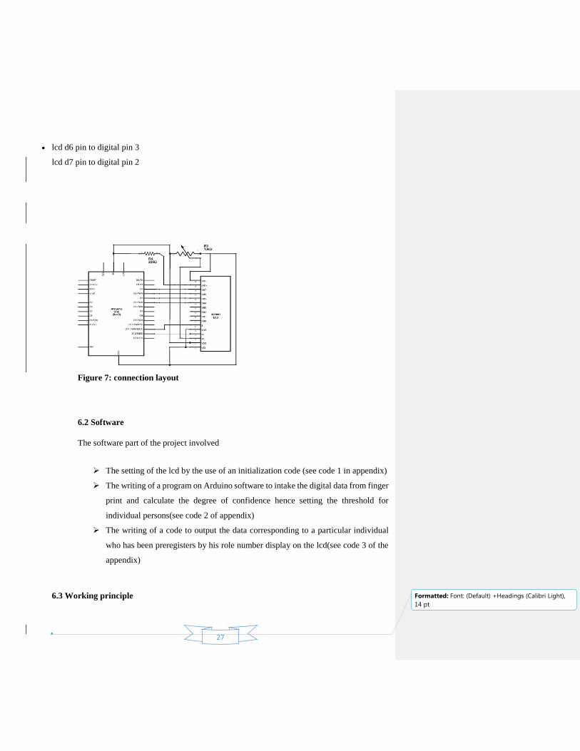
lcd d6 pin to digital pin 3
lcd d7 pin to digital pin 2
Figure 7: connection layout
6.2 Software
The software part of the project involved
The setting of the lcd by the use of an initialization code (see code 1 in appendix)
The writing of a program on Arduino software to intake the digital data from finger
print and calculate the degree of confidence hence setting the threshold for
individual persons(see code 2 of appendix)
The writing of a code to output the data corresponding to a particular individual
who has been preregisters by his role number display on the lcd(see code 3 of the
appendix)
6.3 Working principle

28
Formatted: Font: (Default) +Headings (Calibri Light),
14 pt
The project is based on capturing the fingerprints of individuals then converting
them into digital code with the use of a fingerprint sensor. These digital codes are then fed
into the Arduino Uno board which is loaded with a code to intake and process them by
generating a degree of confidence margin to the code then stored.
When the individual places his hand for the second time, the fingerprint will capture
the data again and compare to the previously stored one then decide whether it matches or
not this is done by another program loaded in to the Arduino board.
All the results corresponding to enrollment and display of information are followed
up by being displayed on the LCD.
By the end of the time allocated for the project. The outcome of the work done was
satisfactory and the enrollment of fingerprints and the corresponding display of roll
numbers, names and sex of the students were archived as well as error massages in case of
mismatching.
6.5 Problems faced
The main problem faced during the accomplishment of the project was coding. The
finding of the wright algorithm for the enrolment and display of information was a
challenge. The other minor problem was the interfacing of the fingerprint to the Arduino
board
6.6 Attempted solutions

29
Formatted: Font: (Default) +Headings (Calibri Light),
14 pt
The association of the Arduino and c++ languages overcame our trouble and
challenges in the enrolment code. The use of a subsidiary code to interface the fingerprint
to the Arduino remedied the later problem
6.7 Conclusion
Having come to the end of the project with subject ‘smart’ attendance system using
‘Arduino Uno’, we can therefore, based on the results obtained that the main purpose of
the project has been achieved. This can be explain by the fact that the project has gone a
long way to foster our skills in programming and to learn and master Arduino language.
Again the increase in knowledge of the functioning of sensors and electrical display devices
has also been a great achievement by the end of the project.
Reference
http://roboromania.ro/arduino_books/MEGA2560-Stater-Kit-Tutoral.pdf
http://creativityprojects.blogspot.com/2013/03/history-of-arduino_4195.html
https://www.google.com/search?q=arduino&rlz=1C1RLNS_enBD763BD763&source=ln
ms&tbm=isch&sa=X&ved=0ahUKEwjr0sGZ07DXAhUD3o8KHfeeAGoQ_AUICigB&
biw=1366&bih=637#imgrc=0EIXfTRwJanX5M:
https://www.elprocus.com/different-types-of-arduino-boards/
https://media.digikey.com/pdf/Data%20Sheets/Arduino%20PDFs/A000046.pdf
http://whatis.techtarget.com/definition/LCD-liquid-crystal-display
https://www.thoughtco.com/liquid-crystal-display-history-lcd-1992078

30
Formatted: Font: (Default) +Headings (Calibri Light),
14 pt
Appendix
Code 1: fingerprint enrolement
#include <LiquidCrystal.h>
#include <Adafruit_Fingerprint.h>
#include <SoftwareSerial.h>
#include "Wire.h"
LiquidCrystal lcd (12, 11, 7, 6, 5, 4);
uint8_t unique_id = 0;
uint8_t getFingerprintEnroll ();
String s_id [5];
String s_name [5];
SoftwareSerial mySerial (2, 3);
Adafruit_Fingerprint finger = Adafruit_Fingerprint(&mySerial);
Void setup ()
{
While (!Serial); // For Yun/Leo/Micro/Zero/...
Delay (500);
Serial.begin(9600);
Serial.println("Adafruit Fingerprint sensor enrollment");
lcd.begin(16, 2);
lcd.print("WELCOME!"); // set the data rate for the sensor serial port
finger.begin(57600);

31
Formatted: Font: (Default) +Headings (Calibri Light),
14 pt
if (finger.verifyPassword()) {
Serial.println("Found fingerprint sensor!");
Serial.println(finger.getTemplateCount());
finger.emptyDatabase();
}
else {
Serial.println("Did not find fingerprint sensor :(");
while (1);
}
}
String names;
void loop() // run over and over again
{
Serial.println("\n\n\nEnroll or search ( e / s ) ?");
lcd.clear();
lcd.print("Enrl/srch(e/s)");
selectOperation();
}
//// -- editing default code here -----------
boolean searching;
void selectOperation ()
{
searching = true;
while (1) {
while (! Serial.available());
char c = Serial.read();
Serial.println(c);
if ( c == 'e') {
enroll();
break;
}

32
Formatted: Font: (Default) +Headings (Calibri Light),
14 pt
if ( c == 's')
{
search();
break;
}
}
}
void search()
{
Serial.println("Waiting for valid finger...");
lcd.clear();
lcd.print("Put your finger");
while (true)
{
if ( -12 == getFingerprintIDez())
continue;
if ( searching)
{
lcd.clear();
lcd.print("INVALID");
Serial.println("INVALID");
delay(2000);
break;
}
delay(50);
}
}
void enroll ()
{
uint8_t id = readnumber();

33
Formatted: Font: (Default) +Headings (Calibri Light),
14 pt
setNames();
Serial.print("Enrolling ID # ");
lcd.clear();
lcd.print("Enrolling...");
Serial.println(id);
Serial.print("Name # ");
Serial.println(s_name[unique_id]);
while (1) {
while (! getFingerprintEnroll(id));
lcd.clear();
lcd.print("Stored!");
lcd.setCursor(0, 1);
lcd.print("ID:");
lcd.setCursor(3, 1);
lcd.print(id);
lcd.setCursor(5, 1);
lcd.print("Name: ");
lcd.setCursor(11, 1);
lcd.print(names[id]);
delay (5000);
break;
}
}
uint8_t readnumber(void) {
Serial.println("Enter the ID #");
lcd.clear();
lcd.print("ID: ");
int count = 0;
while (1) {

34
Formatted: Font: (Default) +Headings (Calibri Light),
14 pt
while (! Serial.available());
delay(10);
char c = Serial.read();
if (isdigit(c)) {
s_id[unique_id] += String(c);
count++;
}
else if (count == 6) {
lcd.setCursor(6, 0);
lcd.print(s_id[unique_id]);
Serial.println(s_id[unique_id] + " : id");
return unique_id;
}
}
}
void setNames()
{
Serial.println("Input the name");
lcd.setCursor(0, 1);
lcd.print("Name: ");
while (1) {
while (! Serial.available());
String n = Serial.readString();
s_name[unique_id] = n;
lcd.print(n);
lcd.setCursor(0, 0);
delay(2000);
break;
}
}
uint8_t getFingerprintID() {

35
Formatted: Font: (Default) +Headings (Calibri Light),
14 pt
uint8_t p = finger.getImage();
switch (p) {
case FINGERPRINT_OK:
Serial.println("Image taken");
break;
case FINGERPRINT_NOFINGER:
Serial.println("No finger detected");
return p;
case FINGERPRINT_PACKETRECIEVEERR:
Serial.println("Communication error");
return p;
case FINGERPRINT_IMAGEFAIL:
Serial.println("Imaging error");
return p;
default:
Serial.println("Unknown error");
return p;
}
// OK success!
p = finger.image2Tz();
switch (p) {
case FINGERPRINT_OK:
Serial.println("Image converted");
break;
case FINGERPRINT_IMAGEMESS:
Serial.println("Image too messy");
return p;
case FINGERPRINT_PACKETRECIEVEERR:
Serial.println("Communication error");
return p;
case FINGERPRINT_FEATUREFAIL:

36
Formatted: Font: (Default) +Headings (Calibri Light),
14 pt
Serial.println("Could not find fingerprint features");
return p;
case FINGERPRINT_INVALIDIMAGE:
Serial.println("Could not find fingerprint features");
return p;
default:
Serial.println("Unknown error");
return p;
}
// OK converted!
p = finger.fingerFastSearch();
if (p == FINGERPRINT_OK) {
Serial.println("Found a print match!");
}
else if (p == FINGERPRINT_PACKETRECIEVEERR) {
Serial.println("Communication error");
return p;
}
else if (p == FINGERPRINT_NOTFOUND) {
Serial.println("Did not find a match");
return p;
}
else {
Serial.println("Unknown error");
return p;
}
// found a match!
Serial.print("Found ID #");
Serial.print(finger.fingerID);
Serial.print(" with confidence of ");
Serial.println(finger.confidence);

37
Formatted: Font: (Default) +Headings (Calibri Light),
14 pt
}
// returns -1 if failed, otherwise returns ID #
int getFingerprintIDez() {
uint8_t p = finger.getImage();
if (p != FINGERPRINT_OK) return -12;
p = finger.image2Tz();
if (p != FINGERPRINT_OK) return -1;
p = finger.fingerFastSearch();
if (p != FINGERPRINT_OK) return -1;
// found a match!
Serial.print("ID #");
Serial.println(s_id[finger.fingerID]);
lcd.clear();
lcd.print("Searching ...");
delay(2000);
lcd.clear();
lcd.print("ID: ");
lcd.setCursor(5, 0);
lcd.print(s_id[finger.fingerID]);
Serial.print("Name #");
Serial.println(s_name[finger.fingerID]);
lcd.setCursor(0, 1);
lcd.print("Name: ");
lcd.setCursor(7, 1);
lcd.print(s_name[finger.fingerID]);
delay(5000);
Serial.print(" with confidence of ");
Serial.println(finger.confidence);
searching = false;
return finger.fingerID;

38
Formatted: Font: (Default) +Headings (Calibri Light),
14 pt
}
uint8_t getFingerprintEnroll(uint8_t id) {
int p = -1;
Serial.print("Waiting for valid finger to enroll as #");
Serial.println(id);
lcd.clear();
lcd.print("Place Finger");
while (p != FINGERPRINT_OK) {
p = finger.getImage();
switch (p) {
case FINGERPRINT_OK:
Serial.println("Image taken");
break;
case FINGERPRINT_NOFINGER:
Serial.println(".");
break;
case FINGERPRINT_PACKETRECIEVEERR:
Serial.println("Communication error");
break;
case FINGERPRINT_IMAGEFAIL:
Serial.println("Imaging error");
break;
default:
Serial.println("Unknown error");
break;
}
}
// OK success!
p = finger.image2Tz(1);
switch (p) {
case FINGERPRINT_OK:

39
Formatted: Font: (Default) +Headings (Calibri Light),
14 pt
Serial.println("Image converted");
break;
case FINGERPRINT_IMAGEMESS:
Serial.println("Image too messy");
return p;
case FINGERPRINT_PACKETRECIEVEERR:
Serial.println("Communication error");
return p;
case FINGERPRINT_FEATUREFAIL:
Serial.println("Could not find fingerprint features");
return p;
case FINGERPRINT_INVALIDIMAGE:
Serial.println("Could not find fingerprint features");
return p;
default:
Serial.println("Unknown error");
return p;
}
Serial.println("Remove finger");
lcd.clear();
lcd.print("Remove finger");
delay(2000);
p = 0;
while (p != FINGERPRINT_NOFINGER) {
p = finger.getImage();
}
Serial.print("ID ");
Serial.println(id);
p = -1;
Serial.println("Place same finger again");
lcd.clear();

40
Formatted: Font: (Default) +Headings (Calibri Light),
14 pt
lcd.print("Place Again");
while (p != FINGERPRINT_OK) {
p = finger.getImage();
switch (p) {
case FINGERPRINT_OK:
Serial.println("Image taken");
break;
case FINGERPRINT_NOFINGER:
Serial.print(".");
break;
case FINGERPRINT_PACKETRECIEVEERR:
Serial.println("Communication error");
break;
case FINGERPRINT_IMAGEFAIL:
Serial.println("Imaging error");
break;
default:
Serial.println("Unknown error");
break;
}
}
// OK success!
p = finger.image2Tz(2);
switch (p) {
case FINGERPRINT_OK:
Serial.println("Image converted");
break;
case FINGERPRINT_IMAGEMESS:
Serial.println("Image too messy");
return p;
case FINGERPRINT_PACKETRECIEVEERR:

41
Formatted: Font: (Default) +Headings (Calibri Light),
14 pt
Serial.println("Communication error");
return p;
case FINGERPRINT_FEATUREFAIL:
Serial.println("Could not find fingerprint features");
return p;
case FINGERPRINT_INVALIDIMAGE:
Serial.println("Could not find fingerprint features");
return p;
default:
Serial.println("Unknown error");
return p;
}
// OK converted!
Serial.print("Creating model for #");
Serial.println(id);
p = finger.createModel();
if (p == FINGERPRINT_OK) {
Serial.println("Prints matched!");
}
else if (p == FINGERPRINT_PACKETRECIEVEERR) {
Serial.println("Communication error");
return p;
}
else if (p == FINGERPRINT_ENROLLMISMATCH) {
Serial.println("Fingerprints did not match");
return p;
}
else {
Serial.println("Unknown error");
return p;
}
42
Formatted: Font: (Default) +Headings (Calibri Light),
14 pt
Serial.print("ID ");
Serial.println(id);
p = finger.storeModel(id);
if (p == FINGERPRINT_OK) {
Serial.println("Stored!");
Serial.print("ID: ");
Serial.println(unique_id);
Serial.print("Name: ");
Serial.println(s_name[unique_id]);
unique_id++; // update to next id
return true; }
else if (p == FINGERPRINT_PACKETRECIEVEERR) {
Serial.println("Communication error");
return p;
}
else if (p == FINGERPRINT_BADLOCATION) {
Serial.println("Could not store in that location");
return p;
}
else if (p == FINGERPRINT_FLASHERR) {
Serial.println("Error writing to flash");
return p;
}
else {
Serial.println("Unknown error");
return p;
}
}

43
Formatted: Font: (Default) +Headings (Calibri Light),
14 pt