Embed Size (px)
Citation preview

Disclosure to Promote the Right To Information
Whereas the Parliament of India has set out to provide a practical regime of right to information for citizens to secure access to information under the control of public authorities, in order to promote transparency and accountability in the working of every public authority, and whereas the attached publication of the Bureau of Indian Standards is of particular interest to the public, particularly disadvantaged communities and those engaged in the pursuit of education and knowledge, the attached public safety standard is made available to promote the timely dissemination of this information in an accurate manner to the public.
इटरनट मानक
“!ान $ एक न' भारत का +नम-ण”Satyanarayan Gangaram Pitroda
“Invent a New India Using Knowledge”
“प0रा1 को छोड न' 5 तरफ”Jawaharlal Nehru
“Step Out From the Old to the New”
“जान1 का अ+धकार, जी1 का अ+धकार”Mazdoor Kisan Shakti Sangathan
“The Right to Information, The Right to Live”
“!ान एक ऐसा खजाना > जो कभी च0राया नहB जा सकता ह”Bhartṛhari—Nītiśatakam
“Knowledge is such a treasure which cannot be stolen”
“Invent a New India Using Knowledge”
ह”ह”ह
IS/ISO 8528-5 (2005): Reciprocating Internal CombustionEngine Driven Alternating Current Generating Sets, Part 5:Generating Sets [TED 2: Automotive Primemovers]

© BIS 2012
November 2012 Price Group 12
B U R E A U O F I N D I A N S T A N D A R D SMANAK BHAVAN, 9 BAHADUR SHAH ZAFAR MARG
NEW DELHI 110002
Hkkjrh; ekud
çR;kxkeh vkarfjd ngu batu pkfyrçR;korhZ èkkjk tujsfVax lsV
Hkkx 5 tujsfVax lsV
Indian StandardRECIPROCATING INTERNAL COMBUSTIONENGINE DRIVEN ALTERNATING CURRENT
GENERATING SETSPART 5 GENERATING SETS
ICS 27.020; 29.160.40
IS/ISO 8528-5 : 2005
Automotive Primemovers Transmission and Steering Systems and Internal Combustion EnginesSectional Committee, TED 2
NATIONAL FOREWORD
This Indian Standard (Part 5) which is identical with ISO 8528-5 : 2005 ‘Reciprocating internalcombustion engine driven alternating current generating sets — Part 5: Generating sets’ issued bythe International Organization for Standardization (ISO) was adopted by the Bureau of Indian Standardson the recommendation of the Automotive Primemovers Transmission and Steering Systems andInternal Combustion Engines Sectional Committee and approval of the Transport Engineering DivisionCouncil.
The text of ISO Standard has been approved as suitable for publication as an Indian Standard withoutdeviations. Certain conventions are, however, not identical to those used in Indian Standards. Attentionis particularly drawn to the following:
a) Wherever the words ‘International Standard’ appear referring to this standard, they should beread as ‘Indian Standard’.
b) Comma (,) has been used as a decimal marker while in Indian Standards, the current practiceis to use a point (.) as the decimal marker.
This standard also makes a reference to the BIS Certification Marking. Details of which are given inNational Annex A.
In this adopted standard, reference appears to certain International Standards for which IndianStandards also exist. The corresponding Indian Standards which are to be substituted in their respectiveplaces are listed below along with their degree of equivalence for the editions indicated:
International Standard Corresponding Indian Standard Degree of Equivalence
ISO 8528-1 : 2005 Reciprocatinginternal combustion engine drivenalternating current generating sets —Part 1: Application, ratings andperformanceISO 8528-2 : 2005 Reciprocatinginternal combustion engine drivenalternating current generating sets —Part 2: EnginesISO 8528-3 : 2005 Reciprocatinginternal combustion engine drivenalternating current generating sets —Part 3: Alternating current generatorsfor generating setsISO 8528-12 : 2005 Reciprocatinginternal combustion engine drivenalternating current generating sets —Part 12: Emergency power suppliesto safety servicesIEC 60034-1 : 2004 Rotat ingelectrical machines — Part 1: Ratingand performance
IS/ISO 8528-1 : 2005 Reciprocatinginternal combustion engine drivenalternating current generating sets:Part 1 Application, ratings andperformanceIS/ISO 8528-2 : 2005 Reciprocatinginternal combustion engine drivenalternating current generating sets:Part 2 EnginesIS/ISO 8528-3 : 2005 Reciprocatinginternal combustion engine drivenalternating current generating sets:Part 3 Alternating current generatorsfor generating setsIS/ISO 8528-5 : 2005 Reciprocatinginternal combustion engine drivenalternating current generating sets:Part 12 Emergency power suppliesto safety servicesIS/IEC 60034-1 : 2004 Rotatingelectrical machines: Part 1 Ratingand performance
Identical
do
do
do
do
(Continued on third cover)

1 Scope
This part of ISO 8528 defines terms and specifies design and performance criteria arising out of the combination of a Reciprocating Internal Combustion (RIC) engine and an Alternating Current (a.c.) generator when operating as a unit.
It applies to a.c. generating sets driven by RIC engines for land and marine use, excluding generating sets used on aircraft or to propel land vehicles and locomotives.
For some specific applications (e.g. essential hospital supplies and high-rise buildings) supplementary requirements may be necessary. The provisions of this part of ISO 8528 should be regarded as a basis for establishing any supplementary requirements.
For generating sets driven by other reciprocating-type prime movers (e.g. steam engines), the provisions of this part of ISO 8528 should be used as a basis for establishing these requirements.
2 Normative references
The following referenced documents are indispensable for the application of this document. For dated references, only the edition cited applies. For undated references, the latest edition of the referenced document (including any amendments) applies.
ISO 3046-4, Reciprocating internal combustion engines — Performance — Part 4: Speed governing
ISO 3046-5, Reciprocating internal combustion engines — Performance — Part 5: Torsional vibrations
ISO 8528-1:2005, Reciprocating internal combustion engine driven alternating current generating sets — Part 1: Application, ratings and performance
ISO 8528-2:2005, Reciprocating internal combustion engine driven alternating current generating sets — Part 2: Engines
ISO 8528-3:2005, Reciprocating internal combustion engine driven alternating current generating sets — Part 3: Alternating current generators for generating sets
ISO 8528-12, Reciprocating internal combustion engine driven alternating current generating sets — Part 12: Emergency power supplies to safety services
IEC 60034-1, Rotating electrical machines — Part 1: Rating and performance
IS/ISO 8528-5 : 2005
1
Indian StandardRECIPROCATING INTERNAL COMBUSTIONENGINE DRIVEN ALTERNATING CURRENT
GENERATING SETSPART 5 GENERATING SETS
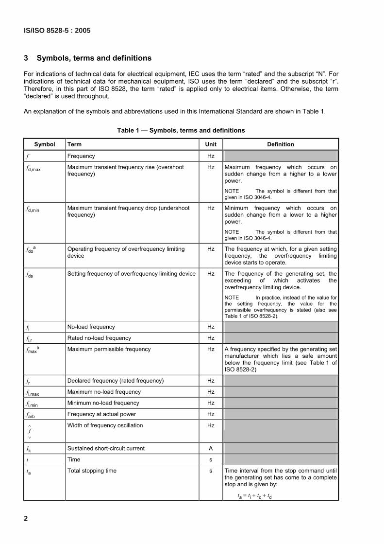
3 Symbols, terms and definitions
For indications of technical data for electrical equipment, IEC uses the term “rated” and the subscript “N”. For indications of technical data for mechanical equipment, ISO uses the term “declared” and the subscript “r”. Therefore, in this part of ISO 8528, the term “rated” is applied only to electrical items. Otherwise, the term “declared” is used throughout.
An explanation of the symbols and abbreviations used in this International Standard are shown in Table 1.
Table 1 — Symbols, terms and definitions
Symbol Term Unit Definition
f Frequency Hz
fd,max Maximum transient frequency rise (overshoot frequency)
Hz Maximum frequency which occurs on sudden change from a higher to a lower power.
NOTE The symbol is different from that given in ISO 3046-4.
fd,min Maximum transient frequency drop (undershoot frequency)
Hz Minimum frequency which occurs on sudden change from a lower to a higher power.
NOTE The symbol is different from that given in ISO 3046-4.
fdoa Operating frequency of overfrequency limiting
device Hz The frequency at which, for a given setting
frequency, the overfrequency limiting device starts to operate.
fds Setting frequency of overfrequency limiting device Hz The frequency of the generating set, the exceeding of which activates the overfrequency limiting device.
NOTE In practice, instead of the value for the setting frequency, the value for the permissible overfrequency is stated (also see Table 1 of ISO 8528-2).
fi No-load frequency Hz
fi,r Rated no-load frequency Hz
fmaxb Maximum permissible frequency Hz A frequency specified by the generating set
manufacturer which lies a safe amount below the frequency limit (see Table 1 of ISO 8528-2)
fr Declared frequency (rated frequency) Hz
fi,max Maximum no-load frequency Hz
fi,min Minimum no-load frequency Hz
farb Frequency at actual power Hz
f∧
∨
Width of frequency oscillation Hz
Ik Sustained short-circuit current A
t Time s
ta Total stopping time s Time interval from the stop command until the generating set has come to a complete stop and is given by:
ta = ti + tc + td
2
IS/ISO 8528-5 : 2005
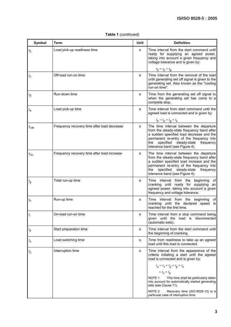
Table 1 (continued)
Symbol Term Unit Definition
tb Load pick-up readiness time s Time interval from the start command until ready for supplying an agreed power, taking into account a given frequency and voltage tolerance and is given by:
tb = tp + tg
tc Off-load run-on time s Time interval from the removal of the load until generating set off signal is given to the generating set. Also known as the "cooling run-on time".
td Run-down time s Time from the generating set off signal to when the generating set has come to a complete stop.
te Load pick-up time s Time interval from start command until the agreed load is connected and is given by:
te = tp + tg + ts
tf,de Frequency recovery time after load decrease s The time interval between the departure from the steady-state frequency band after a sudden specified load decrease and the permanent re-entry of the frequency into the specified steady-state frequency tolerance band (see Figure 4).
tf,in Frequency recovery time after load increase s The time interval between the departure from the steady-state frequency band after a sudden specified load increase and the permanent re-entry of the frequency into the specified steady-state frequency tolerance band (see Figure 4).
tg Total run-up time s Time interval from the beginning of cranking until ready for supplying an agreed power, taking into account a given frequency and voltage tolerance.
th Run-up time s Time interval from the beginning of cranking until the declared speed is reached for the first time.
ti On-load run-on time s Time interval from a stop command being given until the load is disconnected (automatic sets).
tp Start preparation time s Time interval from the start command until the beginning of cranking.
ts Load switching time s Time from readiness to take up an agreed load until this load is connected.
tu Interruption time s Time interval from the appearance of the criteria initiating a start until the agreed load is connected and is given by:
tu = tv + tp + tg + ts
= tv + te
NOTE 1 This time shall be particularly taken into account for automatically started generating sets (see Clause 11).
NOTE 2 Recovery time (ISO 8528-12) is a particular case of interruption time.
IS/ISO 8528-5 : 2005
3
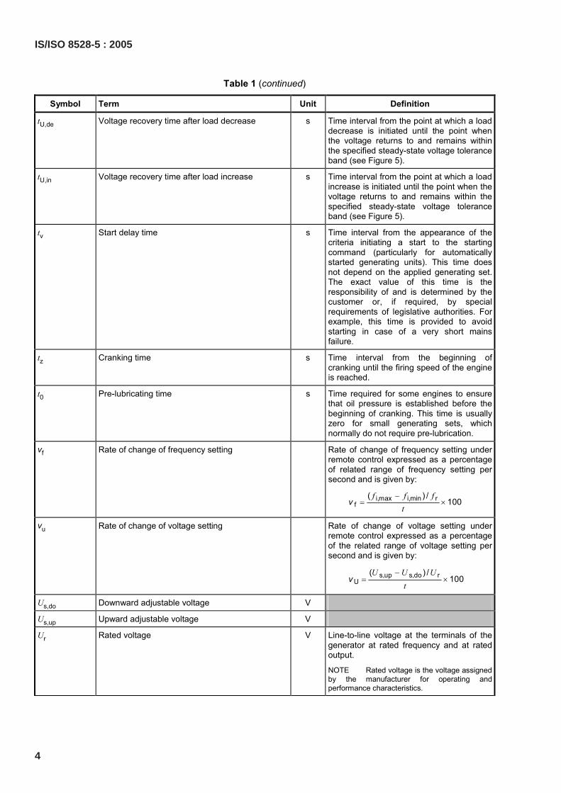
Table 1 (continued)
Symbol Term Unit Definition
tU,de Voltage recovery time after load decrease s Time interval from the point at which a load decrease is initiated until the point when the voltage returns to and remains within the specified steady-state voltage tolerance band (see Figure 5).
tU,in Voltage recovery time after load increase s Time interval from the point at which a load increase is initiated until the point when the voltage returns to and remains within the specified steady-state voltage tolerance band (see Figure 5).
tv Start delay time s Time interval from the appearance of the criteria initiating a start to the starting command (particularly for automatically started generating units). This time does not depend on the applied generating set. The exact value of this time is the responsibility of and is determined by the customer or, if required, by special requirements of legislative authorities. For example, this time is provided to avoid starting in case of a very short mains failure.
tz Cranking time s Time interval from the beginning of cranking until the firing speed of the engine is reached.
t0 Pre-lubricating time s Time required for some engines to ensure that oil pressure is established before the beginning of cranking. This time is usually zero for small generating sets, which normally do not require pre-lubrication.
vf Rate of change of frequency setting Rate of change of frequency setting under remote control expressed as a percentage of related range of frequency setting per second and is given by:
i,max i,min rf
( ) /100
f f ft
−= ×v
vu Rate of change of voltage setting Rate of change of voltage setting under remote control expressed as a percentage of the related range of voltage setting per second and is given by:
s,up s,do rU
( ) /100
U U Ut
−= ×v
Us,do Downward adjustable voltage V
Us,up Upward adjustable voltage V
Ur Rated voltage V Line-to-line voltage at the terminals of the generator at rated frequency and at rated output.
NOTE Rated voltage is the voltage assigned by the manufacturer for operating and performance characteristics.
4
IS/ISO 8528-5 : 2005
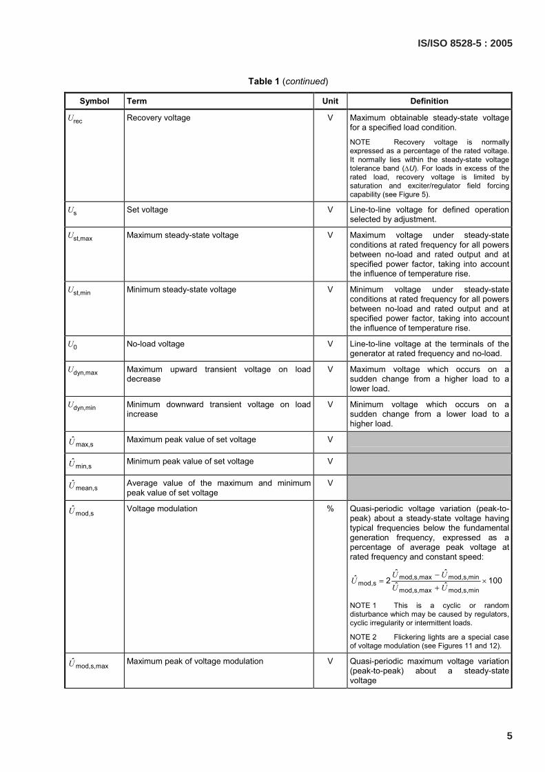
Table 1 (continued)
Symbol Term Unit Definition
Urec Recovery voltage V Maximum obtainable steady-state voltage for a specified load condition.
NOTE Recovery voltage is normally expressed as a percentage of the rated voltage. It normally lies within the steady-state voltage tolerance band (∆U). For loads in excess of the rated load, recovery voltage is limited by saturation and exciter/regulator field forcing capability (see Figure 5).
Us Set voltage V Line-to-line voltage for defined operation selected by adjustment.
Ust,max Maximum steady-state voltage V Maximum voltage under steady-state conditions at rated frequency for all powers between no-load and rated output and at specified power factor, taking into account the influence of temperature rise.
Ust,min Minimum steady-state voltage V Minimum voltage under steady-state conditions at rated frequency for all powers between no-load and rated output and at specified power factor, taking into account the influence of temperature rise.
U0 No-load voltage V Line-to-line voltage at the terminals of the generator at rated frequency and no-load.
Udyn,max Maximum upward transient voltage on load decrease
V Maximum voltage which occurs on a sudden change from a higher load to a lower load.
Udyn,min Minimum downward transient voltage on load increase
V Minimum voltage which occurs on a sudden change from a lower load to a higher load.
max,sU Maximum peak value of set voltage V
min,sU Minimum peak value of set voltage V
mean,sU Average value of the maximum and minimum peak value of set voltage
V
mod,sU Voltage modulation % Quasi-periodic voltage variation (peak-to-peak) about a steady-state voltage having typical frequencies below the fundamental generation frequency, expressed as a percentage of average peak voltage at rated frequency and constant speed:
mod,s,max mod,s,minmod,s
mod,s,max mod,s,min
ˆ ˆˆ 2 100ˆ ˆ
U UU
U U−
= ×+
NOTE 1 This is a cyclic or random disturbance which may be caused by regulators, cyclic irregularity or intermittent loads.
NOTE 2 Flickering lights are a special case of voltage modulation (see Figures 11 and 12).
mod,s,maxU Maximum peak of voltage modulation V Quasi-periodic maximum voltage variation (peak-to-peak) about a steady-state voltage
IS/ISO 8528-5 : 2005
5
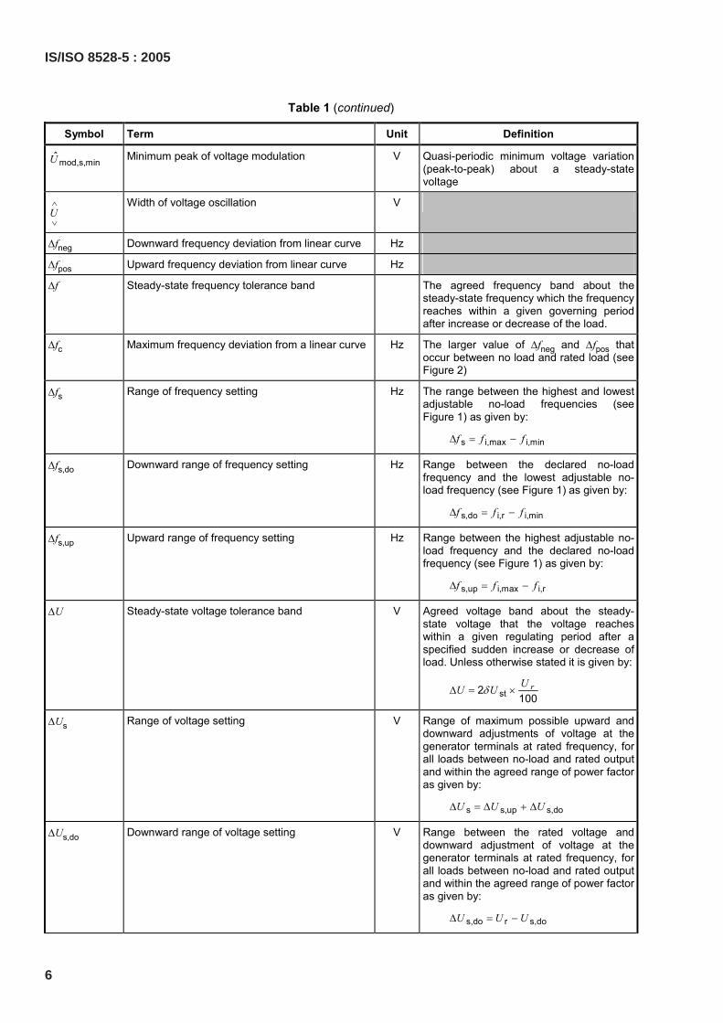
Table 1 (continued)
Symbol Term Unit Definition
mod,s,minU Minimum peak of voltage modulation V Quasi-periodic minimum voltage variation (peak-to-peak) about a steady-state voltage
U∧
∨
Width of voltage oscillation V
∆fneg Downward frequency deviation from linear curve Hz
∆fpos Upward frequency deviation from linear curve Hz
∆f Steady-state frequency tolerance band The agreed frequency band about the steady-state frequency which the frequency reaches within a given governing period after increase or decrease of the load.
∆fc Maximum frequency deviation from a linear curve Hz The larger value of ∆fneg and ∆fpos that occur between no load and rated load (see Figure 2)
∆fs Range of frequency setting Hz The range between the highest and lowest adjustable no-load frequencies (see Figure 1) as given by:
s i,max i,minf f f∆ = −
∆fs,do Downward range of frequency setting Hz Range between the declared no-load frequency and the lowest adjustable no-load frequency (see Figure 1) as given by:
s,do i,r i,minf f f∆ = −
∆fs,up Upward range of frequency setting Hz Range between the highest adjustable no-load frequency and the declared no-load frequency (see Figure 1) as given by:
s,up i,max i,rf f f∆ = −
∆U Steady-state voltage tolerance band V Agreed voltage band about the steady-state voltage that the voltage reaches within a given regulating period after a specified sudden increase or decrease of load. Unless otherwise stated it is given by:
st2100
rUU Uδ∆ = ×
∆Us Range of voltage setting V Range of maximum possible upward and downward adjustments of voltage at the generator terminals at rated frequency, for all loads between no-load and rated output and within the agreed range of power factor as given by:
s s,up s,doU U U∆ = ∆ + ∆
∆Us,do Downward range of voltage setting V Range between the rated voltage and downward adjustment of voltage at the generator terminals at rated frequency, for all loads between no-load and rated output and within the agreed range of power factor as given by:
s,do r s,doU U U∆ = −
6
IS/ISO 8528-5 : 2005
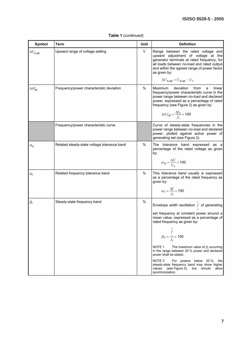
Table 1 (continued)
Symbol Term Unit Definition
∆Us,up Upward range of voltage setting V Range between the rated voltage and upward adjustment of voltage at the generator terminals at rated frequency, for all loads between no-load and rated output and within the agreed range of power factor as given by:
s,up s,up rU U U∆ = −
∆δ fst Frequency/power characteristic deviation % Maximum deviation from a linear frequency/power characteristic curve in the power range between no-load and declared power, expressed as a percentage of rated frequency (see Figure 2) as given by:
cst
r100ff
fδ ∆
∆ = ×
Frequency/power characteristic curve Curve of steady-state frequencies in the power range between no-load and declared power, plotted against active power of generating set (see Figure 2).
αU Related steady-state voltage tolerance band % The tolerance band expressed as a percentage of the rated voltage as given by:
Ur
100UU
α ∆= ×
αf Related frequency tolerance band % This tolerance band usually is expressed as a percentage of the rated frequency as given by:
fr
100ff
α ∆= ×
βf Steady-state frequency band % Envelope width oscillation f
∧
∨ of generating
set frequency at constant power around a mean value, expressed as a percentage of rated frequency as given by:
fr
100f
fβ
∧
∨= ×
NOTE 1 The maximum value of βf occurring in the range between 20 % power and declared power shall be stated.
NOTE 2 For powers below 20 %, the steady-state frequency band may show higher values (see Figure 3), but should allow synchronization.
IS/ISO 8528-5 : 2005
7
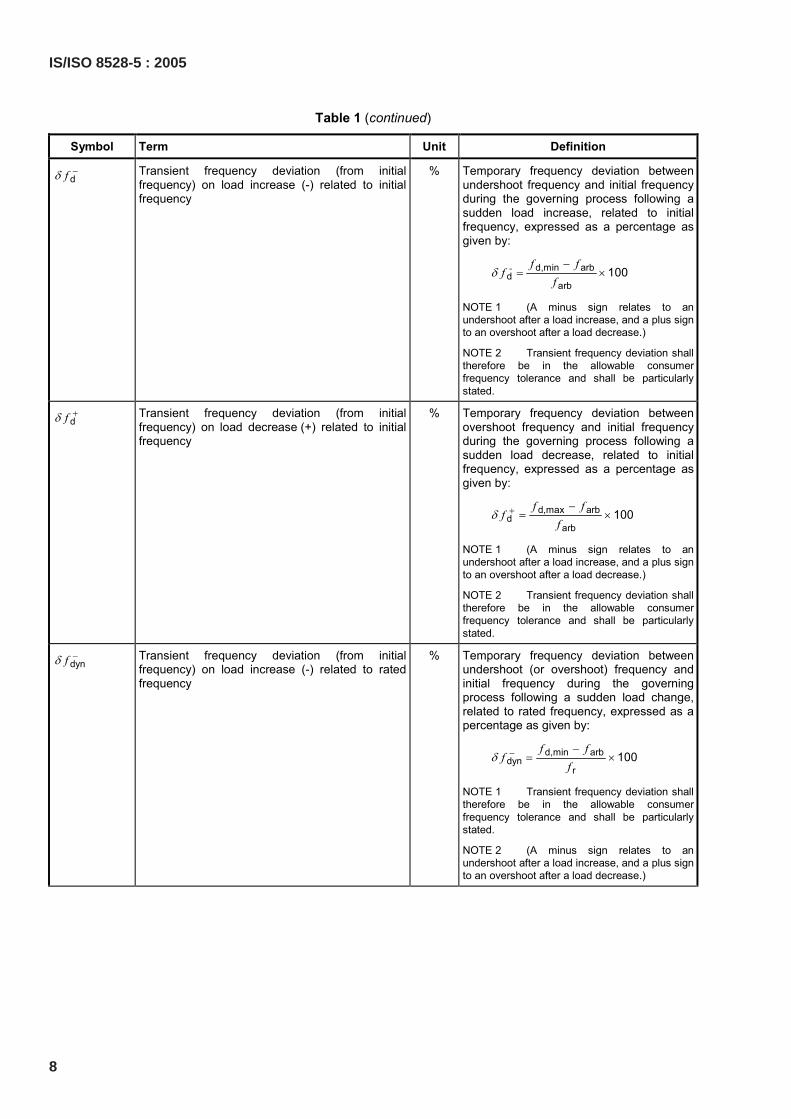
Table 1 (continued)
Symbol Term Unit Definition
dfδ − Transient frequency deviation (from initial frequency) on load increase (-) related to initial frequency
% Temporary frequency deviation between undershoot frequency and initial frequency during the governing process following a sudden load increase, related to initial frequency, expressed as a percentage as given by:
d,min arbd
arb100- f f
ff
δ−
= ×
NOTE 1 (A minus sign relates to an undershoot after a load increase, and a plus sign to an overshoot after a load decrease.)
NOTE 2 Transient frequency deviation shall therefore be in the allowable consumer frequency tolerance and shall be particularly stated.
dfδ + Transient frequency deviation (from initial frequency) on load decrease (+) related to initial frequency
% Temporary frequency deviation between overshoot frequency and initial frequency during the governing process following a sudden load decrease, related to initial frequency, expressed as a percentage as given by:
d,max arbd
arb100
f ff
fδ + −
= ×
NOTE 1 (A minus sign relates to an undershoot after a load increase, and a plus sign to an overshoot after a load decrease.)
NOTE 2 Transient frequency deviation shall therefore be in the allowable consumer frequency tolerance and shall be particularly stated.
dynfδ − Transient frequency deviation (from initial frequency) on load increase (-) related to rated frequency
% Temporary frequency deviation between undershoot (or overshoot) frequency and initial frequency during the governing process following a sudden load change, related to rated frequency, expressed as a percentage as given by:
d,min arbdyn
r100
f ff
fδ − −
= ×
NOTE 1 Transient frequency deviation shall therefore be in the allowable consumer frequency tolerance and shall be particularly stated.
NOTE 2 (A minus sign relates to an undershoot after a load increase, and a plus sign to an overshoot after a load decrease.)
8
IS/ISO 8528-5 : 2005
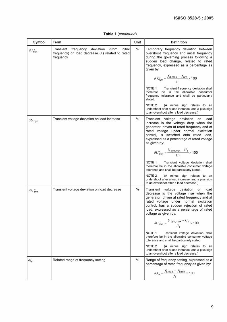
Table 1 (continued)
Symbol Term Unit Definition
dynfδ + Transient frequency deviation (from initial frequency) on load decrease (+) related to rated frequency
% Temporary frequency deviation between overshoot frequency and initial frequency during the governing process following a sudden load change, related to rated frequency, expressed as a percentage as given by:
d,max arbdyn
r100
f ff
fδ + −
= ×
NOTE 1 Transient frequency deviation shall therefore be in the allowable consumer frequency tolerance and shall be particularly stated.
NOTE 2 (A minus sign relates to an undershoot after a load increase, and a plus sign to an overshoot after a load decrease.)
dynUδ − Transient voltage deviation on load increase % Transient voltage deviation on load increase is the voltage drop when the generator, driven at rated frequency and at rated voltage under normal excitation control, is switched onto rated load, expressed as a percentage of rated voltage as given by:
dyn,min rdyn
r100- U U
UU
δ−
= ×
NOTE 1 Transient voltage deviation shall therefore be in the allowable consumer voltage tolerance and shall be particularly stated.
NOTE 2 (A minus sign relates to an undershoot after a load increase, and a plus sign to an overshoot after a load decrease.)
dynUδ + Transient voltage deviation on load decrease % Transient voltage deviation on load decrease is the voltage rise when the generator, driven at rated frequency and at rated voltage under normal excitation control, has a sudden rejection of rated load, expressed as a percentage of rated voltage as given by:
dyn,max rdyn
r100
U UU
Uδ + −
= ×
NOTE 1 Transient voltage deviation shall therefore be in the allowable consumer voltage tolerance and shall be particularly stated.
NOTE 2 (A minus sign relates to an undershoot after a load increase, and a plus sign to an overshoot after a load decrease.)
δ fs Related range of frequency setting % Range of frequency setting, expressed as a percentage of rated frequency as given by:
i,max i,mins
r100
f ff
fδ
−= ×
IS/ISO 8528-5 : 2005
9
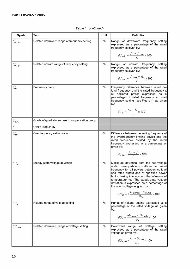
Table 1 (continued)
Symbol Term Unit Definition
δ fs,do Related downward range of frequency setting % Range of downward frequency setting expressed as a percentage of the rated frequency as given by:
i,r i,mins,do
r100
f ff
fδ
−= ×
δ fs,up Related upward range of frequency setting % Range of upward frequency setting expressed as a percentage of the rated frequency as given by:
i,max i,rs,up
r100
f ff
fδ
−= ×
δ fst Frequency droop % Frequency difference between rated no-load frequency and the rated frequency frat declared power expressed as a percentage of rated frequency at fixed frequency setting (see Figure 1) as given by:
i,r rst
r100
f ff
fδ
−= ×
δQCC Grade of quadrature-current compensation droop
δs Cyclic irregularity
δ flim Overfrequency setting ratio % Difference between the setting frequency of the overfrequency limiting device and the rated frequency divided by the rated frequency, expressed as a percentage as given by:
ds rlim
r100f ff
fδ −
= ×
δ Ust Steady-state voltage deviation % Maximum deviation from the set voltage under steady-state conditions at rated frequency for all powers between no-load and rated output and at specified power factor, taking into account the influence of temperature rise. The steady-state voltage deviation is expressed as a percentage of the rated voltage as given by:
st,max st,minst
r100
2U U
UU
δ−
= ± ×
δ Us Related range of voltage setting % Range of voltage setting expressed as a percentage of the rated voltage as given by:
s,up s,dos
r100
U UU
U∆
δ∆ +
= ×
δ Us,do Related downward range of voltage setting % Downward range of voltage setting expressed as a percentage of the rated voltage as given by:
r s,dos,do
r100
U UU
Uδ
−= ×
10
IS/ISO 8528-5 : 2005
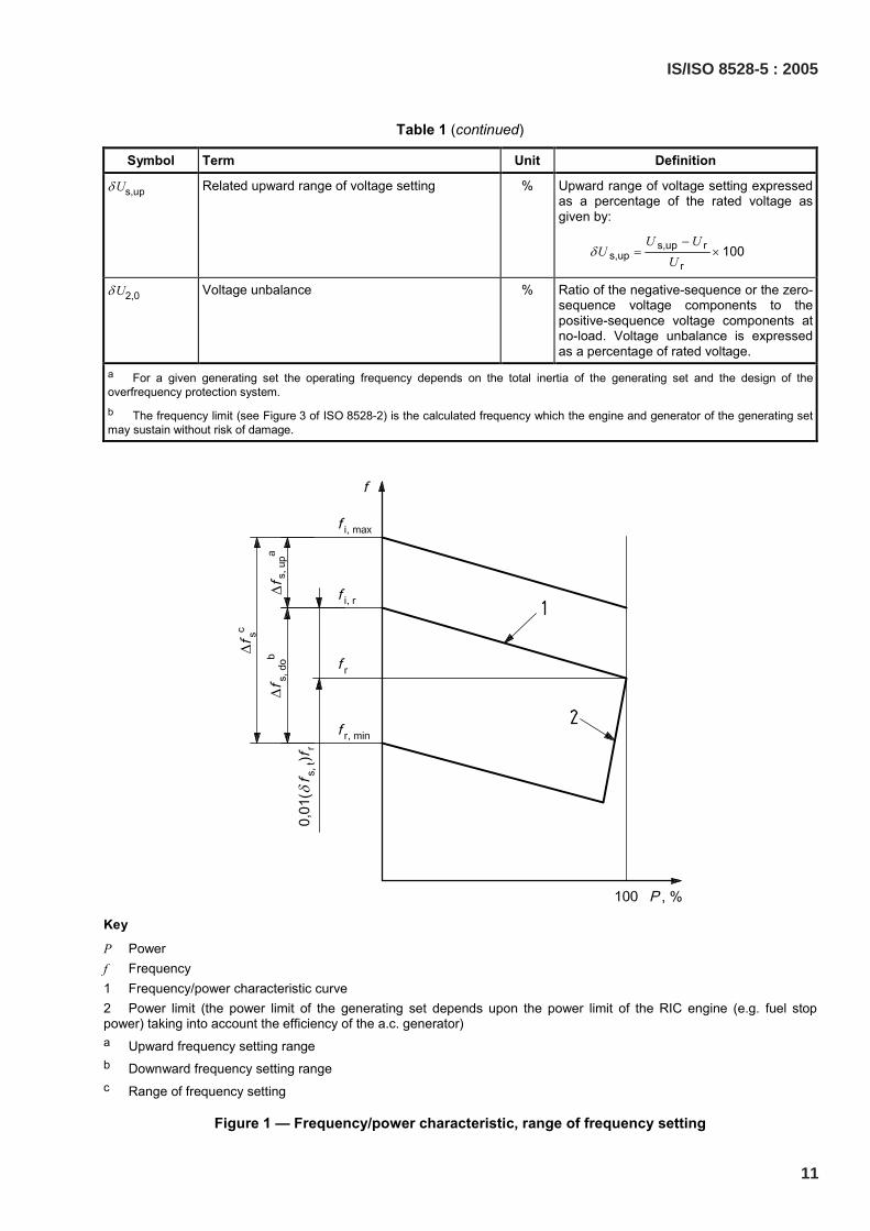
Table 1 (continued)
Symbol Term Unit Definition
δ Us,up Related upward range of voltage setting % Upward range of voltage setting expressed as a percentage of the rated voltage as given by:
s,up rs,up
r100
U UU
Uδ
−= ×
δ U2,0 Voltage unbalance % Ratio of the negative-sequence or the zero-sequence voltage components to the positive-sequence voltage components at no-load. Voltage unbalance is expressed as a percentage of rated voltage.
a For a given generating set the operating frequency depends on the total inertia of the generating set and the design of the overfrequency protection system. b The frequency limit (see Figure 3 of ISO 8528-2) is the calculated frequency which the engine and generator of the generating set may sustain without risk of damage.
Key
P Power f Frequency 1 Frequency/power characteristic curve 2 Power limit (the power limit of the generating set depends upon the power limit of the RIC engine (e.g. fuel stop power) taking into account the efficiency of the a.c. generator) a Upward frequency setting range b Downward frequency setting range c Range of frequency setting
Figure 1 — Frequency/power characteristic, range of frequency setting
IS/ISO 8528-5 : 2005
11
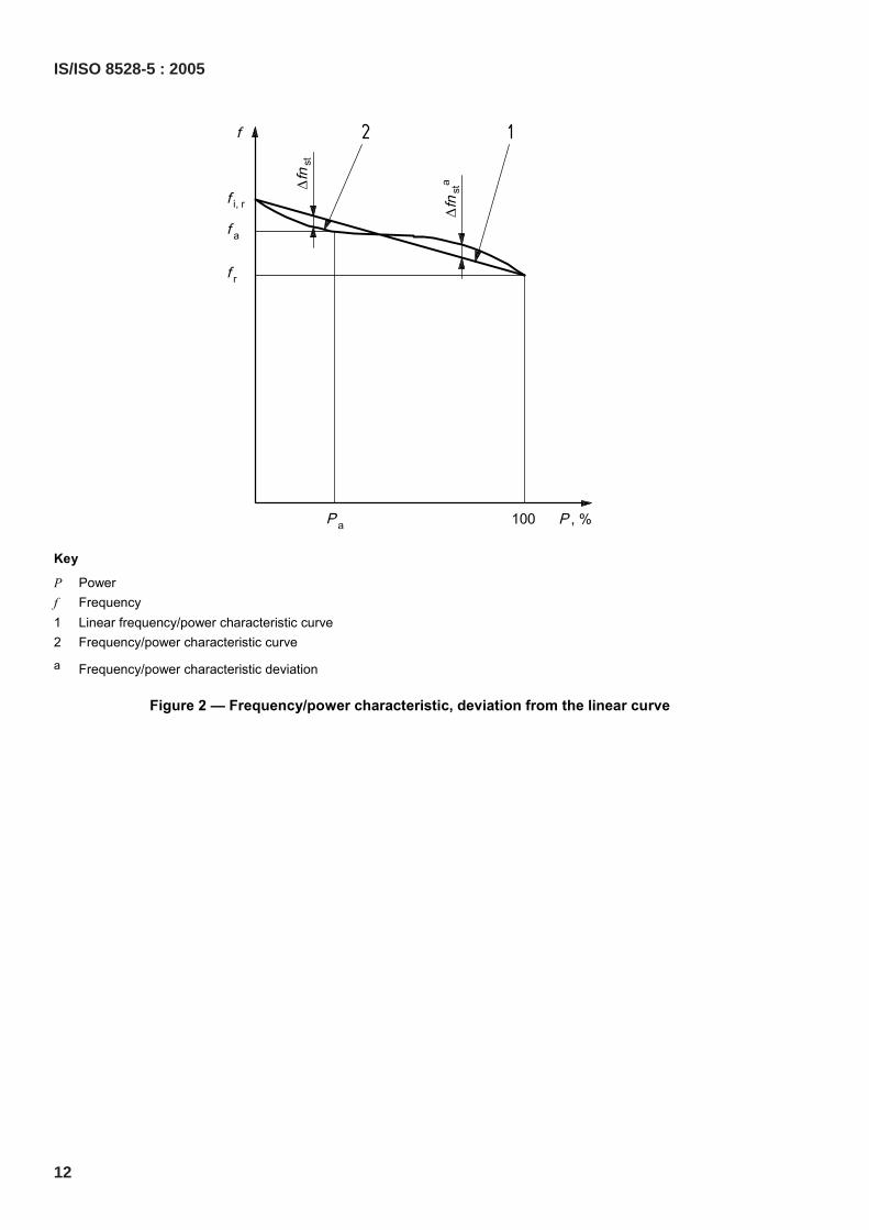
Key
P Power f Frequency 1 Linear frequency/power characteristic curve 2 Frequency/power characteristic curve
a Frequency/power characteristic deviation
Figure 2 — Frequency/power characteristic, deviation from the linear curve
12
IS/ISO 8528-5 : 2005
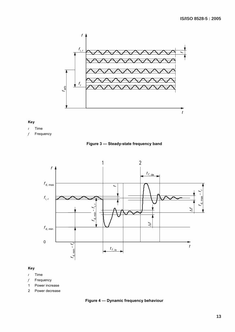
Key
t Time f Frequency
Figure 3 — Steady-state frequency band
Key
t Time f Frequency 1 Power increase 2 Power decrease
Figure 4 — Dynamic frequency behaviour
IS/ISO 8528-5 : 2005
13
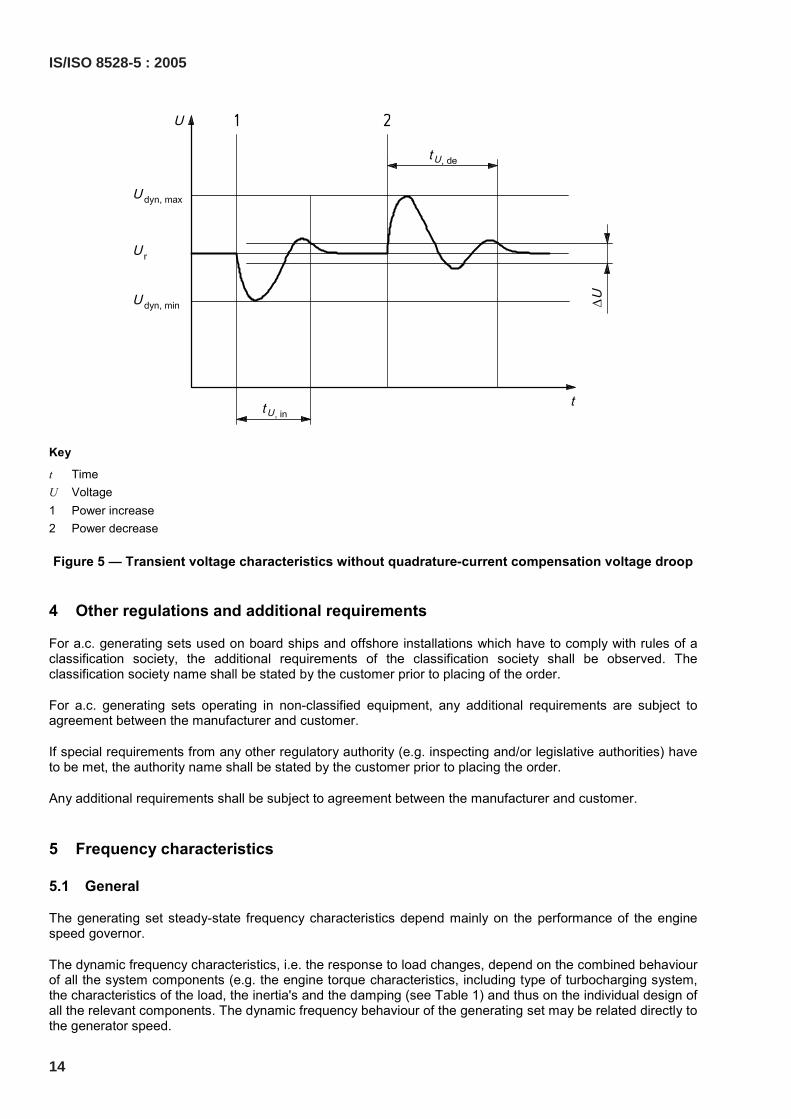
Key
t Time U Voltage 1 Power increase 2 Power decrease
Figure 5 — Transient voltage characteristics without quadrature-current compensation voltage droop
4 Other regulations and additional requirements
For a.c. generating sets used on board ships and offshore installations which have to comply with rules of a classification society, the additional requirements of the classification society shall be observed. The classification society name shall be stated by the customer prior to placing of the order.
For a.c. generating sets operating in non-classified equipment, any additional requirements are subject to agreement between the manufacturer and customer.
If special requirements from any other regulatory authority (e.g. inspecting and/or legislative authorities) have to be met, the authority name shall be stated by the customer prior to placing the order.
Any additional requirements shall be subject to agreement between the manufacturer and customer.
5 Frequency characteristics
5.1 General
The generating set steady-state frequency characteristics depend mainly on the performance of the engine speed governor.
The dynamic frequency characteristics, i.e. the response to load changes, depend on the combined behaviour of all the system components (e.g. the engine torque characteristics, including type of turbocharging system, the characteristics of the load, the inertia's and the damping (see Table 1) and thus on the individual design of all the relevant components. The dynamic frequency behaviour of the generating set may be related directly to the generator speed.
14
IS/ISO 8528-5 : 2005
Terms, symbols and definitions related to frequency characteristics are given in Table 1 (see Figures 1, 2, 3 and 4).
6 Overfrequency characteristics
The terms, symbols and definitions related to overfrequency characteristics are given in Table 1.
7 Voltage characteristics
The generating set voltage characteristics are determined mainly by the inherent design of the a.c. generator and the performance of the automatic voltage regulator. Both the steady-state and the transient frequency characteristics may also influence the generator voltage (see Figure 5).
The terms, symbols and definitions related to voltage characteristics are given in Table 1.
8 Sustained short-circuit current
The sustained short-circuit current, Ik, which may be important to current-operated protective devices, may well be lower in service than the “ideal” value specified by the generator manufacturer for a fault at the generator terminals. The actual value will be influenced by the circuit impedance between the generator and the location of the fault (also see 10.3 of ISO 8528-3).
9 Factors affecting generating set performance
9.1 General
The frequency and voltage performance of a generating set depend on the characteristics of component parts of the generating set.
9.2 Power
Among other factors with respect to the power, the following are particularly relevant and shall be considered when “sizing” the generating set and switchgear:
a) application;
b) power requirements of the connected load;
c) load power factor;
d) starting characteristics of any connected electrical motors;
e) diversity factor of the connected load;
f) intermittent loads; and
g) effect of non-linear loads.
Consideration shall be given to the profile of the connected load in “sizing” the RIC engine and generator, as well as the switchgear.
IS/ISO 8528-5 : 2005
15
9.3 Frequency and voltage
The effect on the transient frequency and voltage characteristics of the generating set to a sudden load change depend on such influences as the following:
a) the turbo-charging system of the RIC engine;
b) brake mean effective pressure, pme, of the RIC engine at declared power;
c) speed governor behaviour;
d) a.c. generator design;
e) a.c. generator excitation system characteristics;
f) voltage regulator behaviour;
g) rotational inertia of the whole generating set.
In order to establish the frequency and voltage characteristics of the generating set due to load changes, it is necessary to determine maximum switched-on or switched-off loads given by the connected load equipment.
9.4 Load acceptance
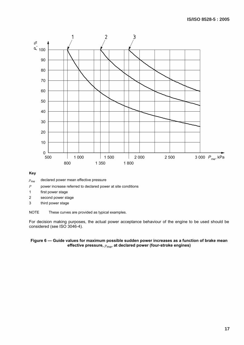
Since it is practically impossible to quantify all influences on the generating set response to dynamic loading, recommended guide values for load application should be given based on the permissible drop in frequency. A higher brake mean effective pressure, pme, usually makes loading in several steps necessary. Figures 6 and 7 show guide values for suddenly applied load steps depending on pme at declared power. The customer shall therefore specify any particular load types or any load acceptance the generating set manufacturer should consider.
The time intervals between the application of consecutive load steps depend on:
a) the swept volume of the RIC engine;
b) the RIC engine brake mean effective pressure;
c) the RIC engine turbo-charging system installed;
d) the type of RIC engine governor installed;
e) the installed voltage regulator characteristics; and
f) the rotational inertia of the complete generating set /RIC engine combination.
If necessary, these time intervals shall be agreed between the generating set manufacturer and the customer.
Criteria for establishing the required minimum rotational inertia are:
a) the permitted drop in frequency;
b) the cyclic irregularity; and
c) if appropriate, the behaviour in case of parallel operation.
16
IS/ISO 8528-5 : 2005
Key
pme declared power mean effective pressure
P power increase referred to declared power at site conditions 1 first power stage 2 second power stage 3 third power stage
NOTE These curves are provided as typical examples.
For decision making purposes, the actual power acceptance behaviour of the engine to be used should be considered (see ISO 3046-4).
Figure 6 — Guide values for maximum possible sudden power increases as a function of brake mean effective pressure, pme, at declared power (four-stroke engines)
IS/ISO 8528-5 : 2005
17
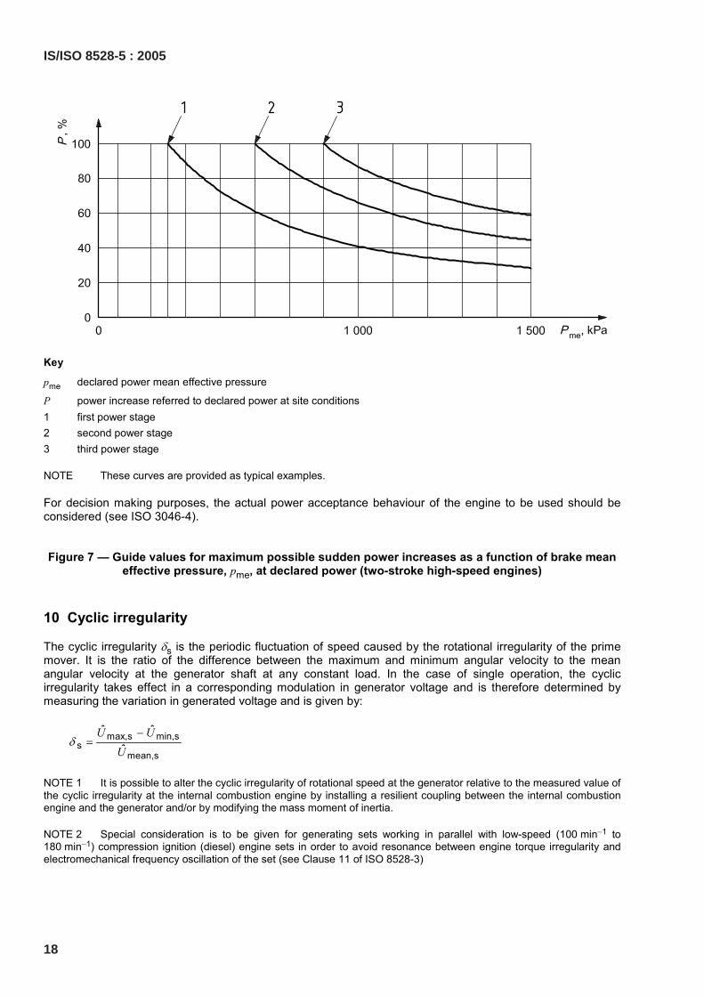
Key
pme declared power mean effective pressure
P power increase referred to declared power at site conditions 1 first power stage 2 second power stage 3 third power stage
NOTE These curves are provided as typical examples.
For decision making purposes, the actual power acceptance behaviour of the engine to be used should be considered (see ISO 3046-4).
Figure 7 — Guide values for maximum possible sudden power increases as a function of brake mean effective pressure, pme, at declared power (two-stroke high-speed engines)
10 Cyclic irregularity
The cyclic irregularity δs is the periodic fluctuation of speed caused by the rotational irregularity of the prime mover. It is the ratio of the difference between the maximum and minimum angular velocity to the mean angular velocity at the generator shaft at any constant load. In the case of single operation, the cyclic irregularity takes effect in a corresponding modulation in generator voltage and is therefore determined by measuring the variation in generated voltage and is given by:
max,s min,ss
mean,s
ˆ ˆˆ
U UU
δ−
=
NOTE 1 It is possible to alter the cyclic irregularity of rotational speed at the generator relative to the measured value of the cyclic irregularity at the internal combustion engine by installing a resilient coupling between the internal combustion engine and the generator and/or by modifying the mass moment of inertia.
NOTE 2 Special consideration is to be given for generating sets working in parallel with low-speed (100 min−1 to 180 min−1) compression ignition (diesel) engine sets in order to avoid resonance between engine torque irregularity and electromechanical frequency oscillation of the set (see Clause 11 of ISO 8528-3)
18
IS/ISO 8528-5 : 2005
11 Starting characteristics
The starting characteristics depend on several factors, e.g.:
a) ambient air temperature;
b) temperature of the RIC engine;
c) starting air pressure;
d) starter battery condition;
e) oil viscosity;
f) total inertia of the generating set;
g) fuel quality; and
h) state of the starting equipment.
They are subject to agreement between the customer and the generating set manufacturer (see Figure 8).
Terms, symbols and definitions related to starting characteristics are given in Table 1.
IS/ISO 8528-5 : 2005
19
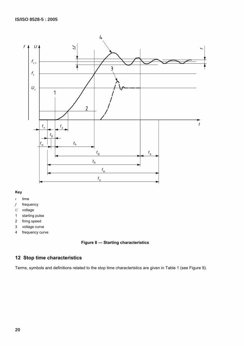
Key
t time f frequency U voltage 1 starting pulse 2 firing speed 3 voltage curve 4 frequency curve
Figure 8 — Starting characteristics
12 Stop time characteristics
Terms, symbols and definitions related to the stop time characteristics are given in Table 1 (see Figure 9).
20
IS/ISO 8528-5 : 2005
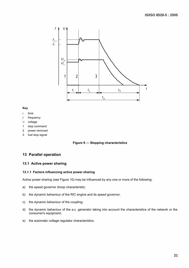
Key
t time f frequency U voltage 1 stop command 2 power removed 3 fuel stop signal
Figure 9 — Stopping characteristics
13 Parallel operation
13.1 Active power sharing
13.1.1 Factors influencing active power sharing
Active power sharing (see Figure 10) may be influenced by any one or more of the following:
a) the speed governor droop characteristic;
b) the dynamic behaviour of the RIC engine and its speed governor;
c) the dynamic behaviour of the coupling;
d) the dynamic behaviour of the a.c. generator taking into account the characteristics of the network or the consumer's equipment;
e) the automatic voltage regulator characteristics.
IS/ISO 8528-5 : 2005
21
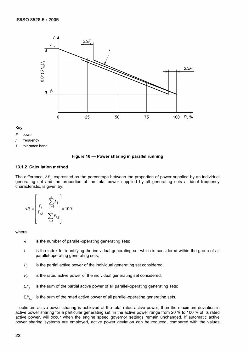
Key
P power f frequency 1 tolerance band
Figure 10 — Power sharing in parallel running
13.1.2 Calculation method
The difference, ∆Pi, expressed as the percentage between the proportion of power supplied by an individual generating set and the proportion of the total power supplied by all generating sets at ideal frequency characteristic, is given by:
j1i
ir,i
r,j1
100
n
jn
j
PPPP
P
=
=
∆ = − ×
∑
∑
where
n is the number of parallel-operating generating sets;
i is the index for identifying the individual generating set which is considered within the group of all parallel-operating generating sets;
Pi is the partial active power of the individual generating set considered;
Pr,i is the rated active power of the individual generating set considered;
ΣPj is the sum of the partial active power of all parallel-operating generating sets;
ΣPr, j is the sum of the rated active power of all parallel-operating generating sets.
If optimum active power sharing is achieved at the total rated active power, then the maximum deviation in active power sharing for a particular generating set, in the active power range from 20 % to 100 % of its rated active power, will occur when the engine speed governor settings remain unchanged. If automatic active power sharing systems are employed, active power deviation can be reduced, compared with the values
22
IS/ISO 8528-5 : 2005

obtained through the engine speed governor characteristics alone. In order to avoid a motoring operation in the event of power deviations between generating sets operating in parallel, appropriate precautions, for example reverse power relays, are required.
13.1.3 Examples of active power sharing
The examples shown in Table 2 are worked assuming a value of cos ϕ = 0,8.
Table 2 — Examples of active power sharing
Related power
Pr,i r,
1
n
jj
P=∑
Partial power
Pi 1
n
jj
P=∑ ,p
r,
ii
i
PPP
= 1s,p
r,1
n
jjn
jj
P
PP
=
=
=∑
∑ ∆Pi Example Genset
kW kW kW kW % % %
1 400 275 68,7 − 6,3
2 400 300 75 0 1
3 400
1200
325
900
81,3
75
+ 6,3
1 400 335 83,7 + 8,7
2 300 210 70 − 5 2
3 200
900
130
675
65
75
− 10
NOTE Power deviation resulting from constant hunting is included in the tolerances for active power sharing. In the event of sudden load changes, the values for constant deviation and hunting in active power sharing may be temporarily exceeded.
13.2 Reactive power sharing
13.2.1 Factors influencing reactive power sharing
Reactive power sharing may be influenced by any one or more of the following:
a) the grade of the quadrature-current compensation voltage droop (δQCC);
b) whether stabilization by equalizer links is present;
c) the automatic reactive power sharing control characteristic;
d) the automatic voltage regulator characteristic.
13.2.2 Calculation method
The difference, ∆Qi, expressed as the percentage between the proportion of reactive power supplied by an individual generating set and the proportion of the total reactive power supplied by all the generating sets at ideal voltage droop characteristic, is given by:
1
r,r,
1
100
n
jji
i njj
j
QQQ
=
=
∆ = − ×
∑
∑
IS/ISO 8528-5 : 2005
23
where
n is the number of parallel-operating generating sets;
i is the index for identifying the individual generating set which is considered within the group of all parallel-operating generating sets;
Qi is the partial reactive power of the individual generating sets considered;
Qr,i is the rated reactive power of the individual generating set considered;
ΣQj is the sum of the partial reactive power of all parallel-operating generating sets;
ΣQr, j is the sum of the rated reactive power of all parallel-operating generating sets.
If optimum reactive power sharing is achieved at the total rated reactive power, then the maximum deviation in reactive power sharing for a particular generating set, in the reactive power range from 20 % to 100 % of its rated reactive power, will occur when the voltage control reference value settings remain unchanged. Exact reactive power sharing is made possible, for example, by:
a) the grade of the quadrature-current compensation voltage droop;
b) whether stabilization equalizer links are present;
c) the automatic reactive power sharing control characteristic.
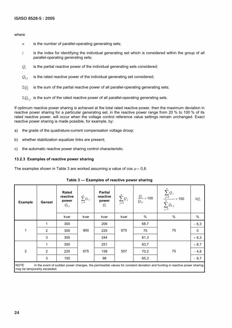
13.2.3 Examples of reactive power sharing
The examples shown in Table 3 are worked assuming a value of cos ϕ = 0,8.
Table 3 — Examples of reactive power sharing
Rated reactive power
Qr,i
r,1
n
jj
Q=∑
Partial reactive power
Qi 1
n
jj
Q=∑
r,100i
i
× 1
r,1
100
n
jjn
jj
Q
Q
=
=
×∑
∑ ∆Qi Example Genset
kvar kvar kvar kvar % % %
1 300 206 68,7 − 6,3
2 300 225 75 0 1
3 300
900
244
675
81,3
75
+ 6,3
1 300 251 83,7 + 8,7
2 225 158 70,2 − 4,8 2
3 150
675
98
507
65,3
75
− 9,7
NOTE In the event of sudden power changes, the permissible values for constant deviation and hunting in reactive power sharing may be temporarily exceeded.
24
IS/ISO 8528-5 : 2005
13.3 Influence on parallel-operating behaviour
The following may have influence on parallel-running behaviour:
a) the speed governor droop characteristic;
b) the dynamic behaviour of the RIC engine and its speed governor;
c) the dynamic behaviour of the coupling;
d) the dynamic behaviour of the a.c. generator, taking into account the relevant reaction of the connected mains or the other parallel-operating generators;
e) the automatic voltage regulator characteristic;
f) the grade of quadrature-current compensation voltage droop (δQCC) of the Automatic Voltage Regulator (AVR).
14 Rating plates
Generating sets shall bear the following rating plates:
a) Generating set rating plate
This shall give at least the following information:
1) the words “Generating set ISO 8528”;
2) the manufacturer’s name or mark;
3) the set serial number;
4) the set year of manufacture;
5) the rated power (kW) with one of the prefixes COP, PRP, LTP or ESP in accordance with the requirements of Clause 13 of ISO 8528-1;
6) the set performance class in accordance with the requirements of Clause 7 of ISO 8528-1;
7) the rated power factor;
8) the maximum site altitude above sea-level (m);
9) the maximum site ambient temperature (ºC);
10) the set rated frequency (Hz);
11) the set rated voltage (V);
12) the set rated current (A);
13) the mass (kg).
b) Rating plate for the RIC engine;
c) Rating plate for generators, in accordance with IEC 60034-1 and Clause 14 of ISO 8528-3;
d) Rating plate for switchgear, where the switchgear is an integral part of the generating set.
NOTE 1 Figure 13 shows an example of a rating plate for a generating set.
NOTE 2 With units rated at less than 10 kW, the information may be combined on a single rating plate.
IS/ISO 8528-5 : 2005
25

Key
t time U voltage
Figure 11 — Sinusoidal voltage modulation of an amplitude a10 and a regular frequency of 10 Hz
Key
f frequency gf frequency weighting factor corresponding to af
Figure 12 — Curve 10f
f
ag
a= giving equivalent perceptibility due to change in brightness
26
IS/ISO 8528-5 : 2005
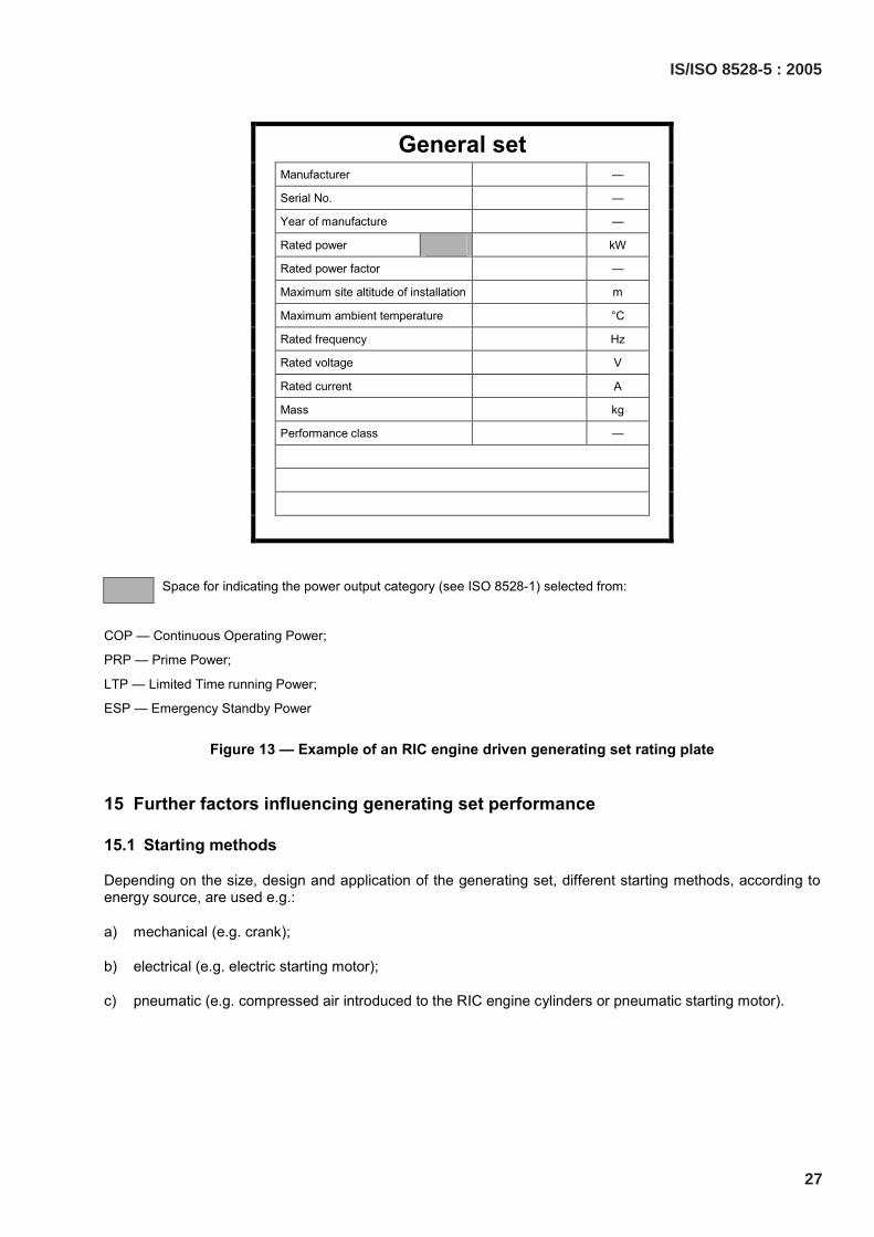
General set Manufacturer —
Serial No. —
Year of manufacture —
Rated power kW
Rated power factor —
Maximum site altitude of installation m
Maximum ambient temperature °C
Rated frequency Hz
Rated voltage V
Rated current A
Mass kg
Performance class —
Space for indicating the power output category (see ISO 8528-1) selected from:
COP — Continuous Operating Power;
PRP — Prime Power;
LTP — Limited Time running Power;
ESP — Emergency Standby Power
Figure 13 — Example of an RIC engine driven generating set rating plate
15 Further factors influencing generating set performance
15.1 Starting methods
Depending on the size, design and application of the generating set, different starting methods, according to energy source, are used e.g.:
a) mechanical (e.g. crank);
b) electrical (e.g. electric starting motor);
c) pneumatic (e.g. compressed air introduced to the RIC engine cylinders or pneumatic starting motor).
IS/ISO 8528-5 : 2005
27
15.2 Shutdown methods
Depending on design and application, different shutdown methods, according to the type of shutdown signal, are used e.g.:
a) mechanical;
b) electrical;
c) pneumatic;
d) hydraulic.
15.3 Fuel and lubrication oil supply
The fuel and lubrication oil supplies shall be designed so that the generating set is able to operate satisfactorily under all operating conditions. Furthermore, safety requirements (e.g. for fire and explosion protection) should be taken into account. The appropriate regulations of the legislative authorities of the respective country for fuel and lubricating oil storage shall be complied with.
15.4 Combustion air
The quality of air required for combustion shall be taken into account to determine the degree of filtration required.
15.5 Exhaust system
The exhaust system shall be designed in accordance with the permitted exhaust gas back pressure (stated by the engine manufacturer) and the required noise attenuation. The following criteria may be important in designing the system:
a) whether structure-borne sound insulation is installed/required;
b) whether heat insulation and cladding (radiation, penetrations through walls, protection against contact) is installed/required;
c) whether piping expansion compensation is installed/required;
d) drainage;
e) prevention of water ingress;
f) protection against exhaust gas explosion;
g) configuration of the exhaust outlet (e.g. direction of wind, protection against birds);
h) support;
i) gaseous emissions.
15.6 Cooling and room ventilation
The RIC engine cooling system type, the generator and the switchgear as well as ventilation and air extraction are of particular importance for stationary power plants when designing the site building. In order to design the site building correctly, the required technical data shall be obtained from the generating set manufacturer.
28
IS/ISO 8528-5 : 2005

15.7 Monitoring
The extent of monitoring of a power plant depends on, e.g.:
a) the intended application;
b) the mode of operation;
c) the size and type of the generating set;
d) requirements of the consumer’s equipment;
e) the manufacturer’s requirements;
f) the customer’s requirements.
In observing the above criteria, the monitoring equipment shall be chosen to ensure readiness for use and operation.
15.8 Noise emission
If the fixed installation generating set noise emission is to be limited to certain values, then a special agreement shall be made between the manufacturer and the customer at the project stage.
If sound level measurements are agreed for mobile generating sets, then measurements should be carried out at the manufacturer’s works using short-range field measurements.
NOTE 1 An enveloping surface method is given in ISO 8528-10.
NOTE 2 In practice, the expensive measurements according to the long-range field measurements give no appreciable difference from those of short-range measurements.
As with fixed equipment, treatment for noise attenuation is usually taken on site, and the sound level measurements at the manufacturer’s works can only be carried out without this noise attenuation. If noise attenuation of the generating set is required, the measurement may be carried out as for mobile generating sets.
15.9 Coupling
The generating set/RIC engine coupling selection shall take into account the stresses imposed on it by the torsional vibration of the system which is influenced by, e.g.:
a) up to RIC engine fuel stop power;
b) the inertia of the RIC engine and generator;
c) the short-circuit torque;
d) misalignment;
e) RIC engine misfiring.
The greatest short-circuit torque occurs as a result of a two-phase Iine-to-Iine short circuit at the generator terminals. However, in many instances the ratio of generator inertia to engine inertia is so large that the torque on the coupling may be little more than, or even less than, the continuous power torque.
The generating set manufacturer is responsible for component compatibility.
IS/ISO 8528-5 : 2005
29
15.10 Vibration
15.10.1 General
The generating set manufacturer shall demonstrate that for the vibrating system (engine/coupling/generator/ baseframe) of the generating set, the vibration characteristic in its normal operating range will lie safely outside the range of critical values.
The vibrations caused by other parts of the power station (e.g. exhaust gas system, foundations) shall also be taken into account.
15.10.2 Torsional vibration
The provisions of ISO 3046-5 shall be used to perform the torsional vibration analysis of the generating set.
The manufacturer of the generating set shall be responsible for ensuring that the torsional vibrations lie safely outside the range of critical values.
When previously agreed by contract, the manufacturer of the generating set shall be responsible for performing calculations and for making measurements of its torsional vibration characteristics.
The results of measurements and/or calculations of torsional vibrations shall be agreed between the manufacturer of the generating set, the RIC engine and driven machinery manufacturers and by the inspecting and/or legislative authorities and/or classification societies, when applicable.
15.10.3 Linear vibration
15.10.3.1 Dynamic bending deformation
Dynamic bending deformation in the rotating system consisting of the engine/coupling/generator combination may occur due to the effects of combustion and inertial forces in the engine and the magnetic forces in the generator. Dynamic bending deformation shall be taken into account in the design of individual components and of the baseframe.
15.10.3.2 Structural vibrations
15.10.3.2.1 General
Apart from the torsional and linear vibrations, there exist vibrations of the generating set caused by the reciprocating forces and torques present in the RIC engine. The manufacturer of the generating set shall be responsible for the compatibility of the components relative to each other, so that the maximum permitted vibration velocity for individual components is not exceeded.
15.10.3.2.2 Measurement location and measurement conditions
Measurements shall be carried out in the horizontal and/or vertical direction at the generating set bearings. When a bearing is not accessible, or for single-bearing a.c. generators, the measurement shall be carried out on the bearing casing. The measurement of the vibration velocity should preferably be carried out with the generating set installed on the manufacturer’s test-bed and running at its rated output and, if possible, under simulated site installation conditions. Where the rated output cannot be applied for this test, then the highest possible output shall be applied.
15.11 Foundations
In order to be able to establish the dimensions of the generating set baseplate foundations or any supporting surfaces, data on static and dynamic loads to be expected shall be obtained from the generating set manufacturer.
30
IS/ISO 8528-5 : 2005
To reduce the effect of free inertia forces on the environment, a suitable resilient mounting may be necessary.
Any openings required for cables, pipelines, etc., at the site shall be taken into account.
If a resilient mounting is provided, then flexible connections shall be provided for cables and pipes.
16 Performance class operating limit values
The operating limit values Iisted in Table 4 shall be satisfied in order to determine the major characteristics of significance for the voltage and frequency behaviour of a generating set as given in ISO 8528-1.
The numerical values for the individual performance classes shall be selected so that they are matched for the compatibility of their individual component parts.
The appropriate performance class for a generating set shall be selected when all the limit values for this performance class have been fulfilled.
It is recommended that the customer should select the minimum performance class that will fulfil his requirements.
IS/ISO 8528-5 : 2005
31
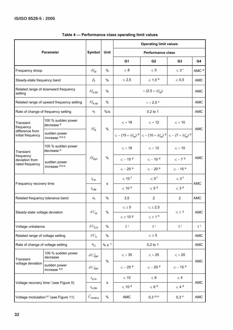
Table 4 — Performance class operating limit values
Operating limit values
Performance class Parameter Symbol Unit
G1 G2 G3 G4
Frequency droop δ fst % u 8 u 5 u 3 r AMC a
Steady-state frequency band βf % u 2,5 u 1,5 b u 0,5 AMC
Related range of downward frequency setting
δ fs,do % > (2,5 + δ fst) AMC
Related range of upward frequency setting δ fs,up % > + 2,5 c AMC
Rate of change of frequency setting vf %/s 0,2 to 1 AMC
100 % sudden power decrease p u + 18 u + 12 u + 10 Transient
frequency difference from initial frequency sudden power
increase d,e,q
δ fd %
u − (15 + δ fst) d u − (10 + δ fst) d u − (7 + δ fst) d
AMC
100 % sudden power decrease p u + 18 u + 12 u + 10
u − 15 d u − 10 d u − 7 d
Transient frequency deviation from rated frequency sudden power
increase d,e,q
δ fdyn %
u − 25 e u − 20 e u − 15 e
AMC
tf,in u 10 f u 5 f u 3 f Frequency recovery time
tf,de s
u 10 d u 5 d u 3 d AMC
Related frequency tolerance band αf % 3,5 2 2 AMC
u ± 5 u ± 2,5 Steady-state voltage deviation δ Ust %
u ± 10 g u ± 1 h u ± 1 AMC
Voltage unbalance δ U2,0 % 1 i 1 i 1 i 1 i
Related range of voltage setting δ Us % u ± 5 AMC
Rate of change of voltage setting vU % s−1 0,2 to 1 AMC
100 % sudden power decrease dynUδ + u + 35 u + 25 u + 20
Transient voltage deviation sudden power
increase d,e dynUδ −
% u − 25 d u − 20 d u − 15 d
AMC
tU,in u 10 u 6 u 4 Voltage recovery time j (see Figure 5)
tU,de s
u 10 d u 6 d u 4 d AMC
Voltage modulation k,l (see Figure 11) mod,sU % AMC 0,3 m,n 0,3 n AMC
32
IS/ISO 8528-5 : 2005
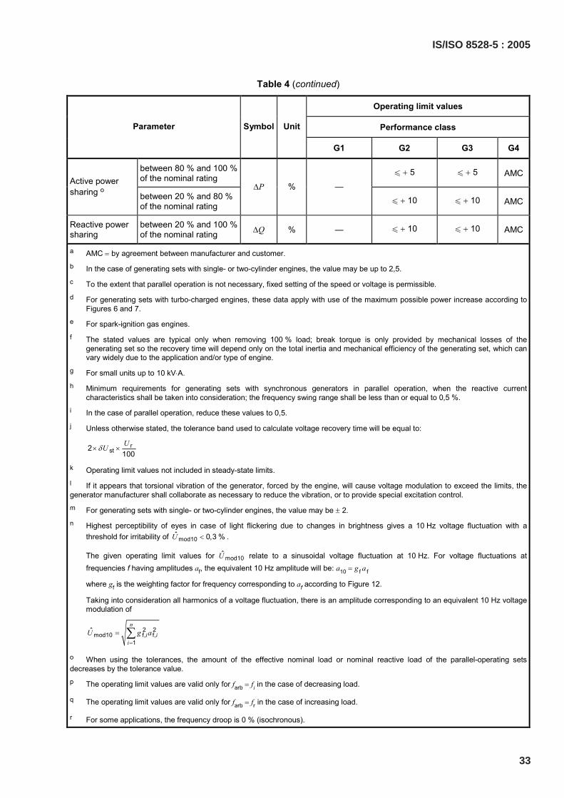
Table 4 (continued)
Operating limit values
Performance class Parameter Symbol Unit
G1 G2 G3 G4
between 80 % and 100 % of the nominal rating
u + 5 u + 5 AMC Active power sharing o between 20 % and 80 %
of the nominal rating
∆P % — u + 10 u + 10 AMC
Reactive power sharing
between 20 % and 100 % of the nominal rating ∆Q % — u + 10 u + 10 AMC
a AMC = by agreement between manufacturer and customer. b In the case of generating sets with single- or two-cylinder engines, the value may be up to 2,5. c To the extent that parallel operation is not necessary, fixed setting of the speed or voltage is permissible. d For generating sets with turbo-charged engines, these data apply with use of the maximum possible power increase according to
Figures 6 and 7. e For spark-ignition gas engines. f The stated values are typical only when removing 100 % load; break torque is only provided by mechanical losses of the
generating set so the recovery time will depend only on the total inertia and mechanical efficiency of the generating set, which can vary widely due to the application and/or type of engine.
g For small units up to 10 kV⋅A. h Minimum requirements for generating sets with synchronous generators in parallel operation, when the reactive current
characteristics shall be taken into consideration; the frequency swing range shall be less than or equal to 0,5 %. i In the case of parallel operation, reduce these values to 0,5. j Unless otherwise stated, the tolerance band used to calculate voltage recovery time will be equal to:
rst2
100UUδ× ×
k Operating limit values not included in steady-state limits. l If it appears that torsional vibration of the generator, forced by the engine, will cause voltage modulation to exceed the limits, the generator manufacturer shall collaborate as necessary to reduce the vibration, or to provide special excitation control. m For generating sets with single- or two-cylinder engines, the value may be ± 2. n Highest perceptibility of eyes in case of light flickering due to changes in brightness gives a 10 Hz voltage fluctuation with a
threshold for irritability of mod10ˆ 0,3 %U < .
The given operating limit values for mod10U relate to a sinusoidal voltage fluctuation at 10 Hz. For voltage fluctuations at frequencies f having amplitudes af, the equivalent 10 Hz amplitude will be: a10 = g f a f
where gf is the weighting factor for frequency corresponding to af according to Figure 12.
Taking into consideration all harmonics of a voltage fluctuation, there is an amplitude corresponding to an equivalent 10 Hz voltage modulation of
2 2mod10 f, f,
1
ˆn
i ii
U g a=
= ∑
o When using the tolerances, the amount of the effective nominal load or nominal reactive load of the parallel-operating sets decreases by the tolerance value. p The operating limit values are valid only for farb = fi in the case of decreasing load.
q The operating limit values are valid only for farb = fr in the case of increasing load.
r For some applications, the frequency droop is 0 % (isochronous).
IS/ISO 8528-5 : 2005
33
Bibliography
[1] ISO 8528-2:1993, Reciprocating internal combustion engine driven alternating current generating sets — Part 2: Engines
[2] ISO 8528-10:1998, Reciprocating internal combustion engine driven alternating current generating sets — Part 10: Measurement of airborne noise by the enveloping surface method
34
IS/ISO 8528-5 : 2005
IS/ISO 8528-5 : 2005
35
NATIONAL ANNEX A(National Foreword)
A-1 BIS CERTIFICATION MARKING
RIC engine driven ac generating set may also be marked with the Standard Mark.
A-1.1 The use of the Standard Mark is governed by the provisions of the Bureau of Indian StandardsAct, 1986 and the Rules and Regulations made thereunder. The details of conditions under which thelicence for the use of the Standard Mark may be granted to manufacturers or producers may beobtained from the Bureau of Indian Standards.

(Continued from second cover)
The technical committee has reviewed the provisions of the following International Standards referredin this adopted standard and has decided that they are acceptable for use in conjunction with thisstandard:
International Standard Title
ISO 3046-4 Reciprocating internal combustion engines — Performance — Part 4:Speed governing
ISO 3046-5 Reciprocating internal combustion engines — Performance — Part 5:Torsional vibrations
For the purpose of deciding whether a particular requirement of this standard is complied with, thefinal value, observed or calculated, expressing the result of a test or analysis, shall be rounded off inaccordance with IS 2 : 1960 ‘Rules for rounding off numerical values (revised)’. The number ofsignificant places retained in the rounded off value should be the same as that of the specified valuein this standard.
Bureau of Indian Standards
BIS is a statutory institution established under the Bureau of Indian Standards Act, 1986 to promoteharmonious development of the activities of standardization, marking and quality certification of goodsand attending to connected matters in the country.
Copyright
BIS has the copyright of all its publications. No part of these publications may be reproduced in any formwithout the prior permission in writing of BIS. This does not preclude the free use, in course of imple-menting the standard, of necessary details, such as symbols and sizes, type or grade designations.Enquiries relating to copyright be addressed to the Director (Publications), BIS.
Review of Indian Standards
Amendments are issued to standards as the need arises on the basis of comments. Standards are alsoreviewed periodically; a standard along with amendments is reaffirmed when such review indicates thatno changes are needed; if the review indicates that changes are needed, it is taken up for revision. Usersof Indian Standards should ascertain that they are in possession of the latest amendments or edition byreferring to the latest issue of ‘BIS Catalogue’ and ‘Standards: Monthly Additions’.
This Indian Standard has been developed from Doc No.: TED 2 (777).
Amendments Issued Since Publication______________________________________________________________________________________
Amendment No. Date of Issue Text Affected______________________________________________________________________________________
______________________________________________________________________________________
______________________________________________________________________________________
______________________________________________________________________________________
______________________________________________________________________________________
BUREAU OF INDIAN STANDARDSHeadquarters:
Manak Bhavan, 9 Bahadur Shah Zafar Marg, New Delhi 110002Telephones: 2323 0131, 2323 3375, 2323 9402 Website: www.bis.org.in
Regional Offices: Telephones
Central : Manak Bhavan, 9 Bahadur Shah Zafar Marg 2323 7617NEW DELHI 110002 2323 3841
Eastern : 1/14, C.I.T. Scheme VII M, V.I.P. Road, Kankurgachi 2337 8499, 2337 8561KOLKATA 700054 2337 8626, 2337 9120
Northern : SCO 335-336, Sector 34-A, CHANDIGARH 160022 260 3843260 9285
Southern : C.I.T. Campus, IV Cross Road, CHENNAI 600113 2254 1216, 2254 14422254 2519, 2254 2315
Western : Manakalaya, E9 MIDC, Marol, Andheri (East) 2832 9295, 2832 7858MUMBAI 400093 2832 7891, 2832 7892
Branches: AHMEDABAD. BANGALORE. BHOPAL. BHUBANESHWAR. COIMBATORE. DEHRADUN.FARIDABAD. GHAZIABAD. GUWAHATI. HYDERABAD. JAIPUR. KANPUR. LUCKNOW.NAGPUR. PARWANOO. PATNA. PUNE. RAJKOT. THIRUVANATHAPURAM. VISAKHAPATNAM.
Published by BIS, New Delhi
{
{{
{{