Embed Size (px)
Citation preview
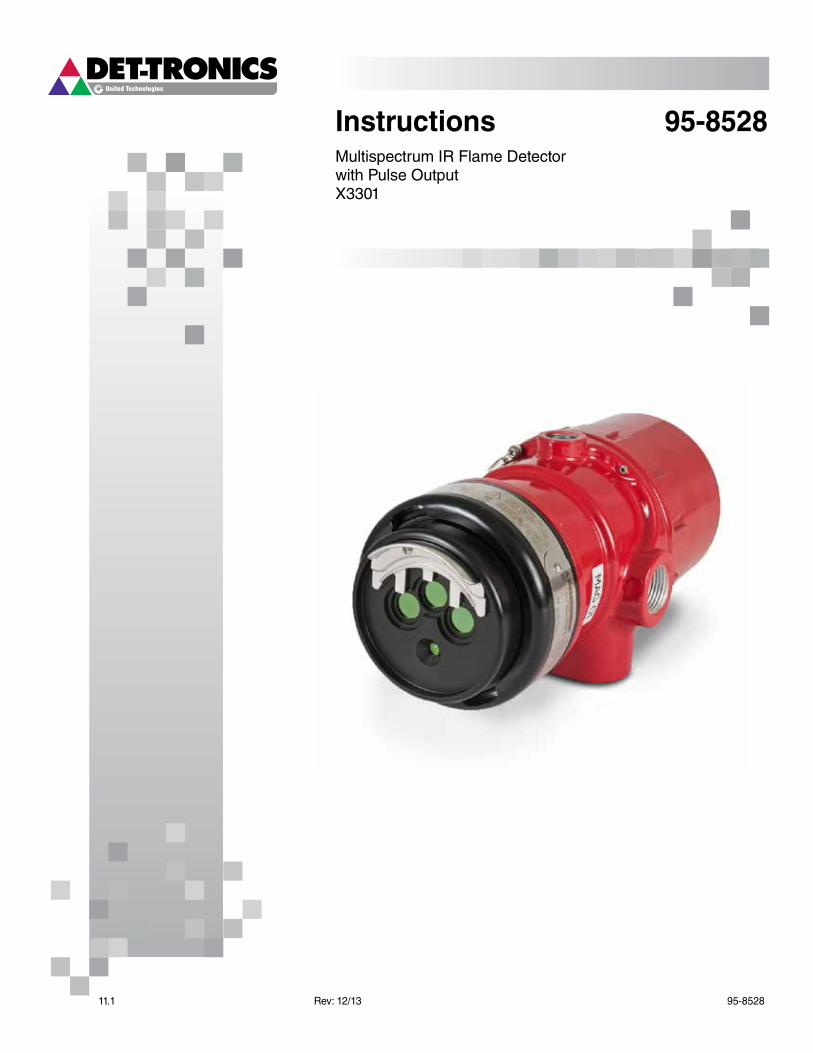
Instructions 95-8528Multispectrum IR Flame Detectorwith Pulse OutputX3301
11.1 Rev: 12/13 95-8528
Table of Contents
DESCRIPTION . . . . . . . . . . . . . . . . . . . . . . . . . . . . . . 1
Outputs . . . . . . . . . . . . . . . . . . . . . . . . . . . . . . . . 2
LED . . . . . . . . . . . . . . . . . . . . . . . . . . . . . . . . . . . 2
oi (Optical Integrity) . . . . . . . . . . . . . . . . . . . . . . 2
Communication . . . . . . . . . . . . . . . . . . . . . . . . . . 3
Data Logging . . . . . . . . . . . . . . . . . . . . . . . . . . . . 3
Integral Wiring Compartment . . . . . . . . . . . . . . . . 3
Detector Sensitivity Levels . . . . . . . . . . . . . . . . . . 3
GENERaL aPPLICaTION INfORmaTION . . . . . . . . 4
Response Characteristics . . . . . . . . . . . . . . . . . . 4
Important application Considerations . . . . . . . . . 4
ImPORTaNT SafETy NOTES . . . . . . . . . . . . . . . . . 4
INSTaLLaTION . . . . . . . . . . . . . . . . . . . . . . . . . . . . . 5
Detector Positioning . . . . . . . . . . . . . . . . . . . . . . . 5
Detector Orientation . . . . . . . . . . . . . . . . . . . . . . . 5
Protection against moisture Damage . . . . . . . . . 6
Wiring Procedure . . . . . . . . . . . . . . . . . . . . . . . . . 6
STaRTUP PROCEDURE . . . . . . . . . . . . . . . . . . . . . 14
manual oi Test (Output to Controller) . . . . . . . . 14
Count Test mode (Output to Controller) . . . . . . . . 14
fire alarm Test (Pulse Output to fire alarm Panel) . .15
TROUBLESHOOTING . . . . . . . . . . . . . . . . . . . . . . . 15
maINTENaNCE . . . . . . . . . . . . . . . . . . . . . . . . . . . . 16
Cleaning Procedure . . . . . . . . . . . . . . . . . . . . . . 16
oi Plate Removal and Replacement . . . . . . . . . 16
Periodic Checkout Procedure . . . . . . . . . . . . . . 17
Clock Battery . . . . . . . . . . . . . . . . . . . . . . . . . . . 17
fEaTURES . . . . . . . . . . . . . . . . . . . . . . . . . . . . . . . . 17
SPECIfICaTIONS . . . . . . . . . . . . . . . . . . . . . . . . . . 17
REPLaCEmENT PaRTS . . . . . . . . . . . . . . . . . . . . . 19
DEVICE REPaIR aND RETURN . . . . . . . . . . . . . . . 19
ORDERING INfORmaTION . . . . . . . . . . . . . . . . . . 19
accessories . . . . . . . . . . . . . . . . . . . . . . . . . . . . 19
X3301 model matrix . . . . . . . . . . . . . . . . . . . . . . 20
aPPENDIX a – fm aPPROVaL aND PERfORmaNCE REPORT . . . . . . . . . . . . . . . . . . . 21
aPPENDIX B – CSa aPPROVaL . . . . . . . . . . . . . . . 31
aPPENDIX C – aTEX / CE aPPROVaL . . . . . . . . . . 32
aPPENDIX D – IECEx aPPROVaL . . . . . . . . . . . . . 34
aPPENDIX E – EN54 aPPROVaLS . . . . . . . . . . . . . 35
aPPENDIX f – aDDITIONaL aPPROVaLS . . . . . . 36
1 95-852811.1
INSTRUCTIONS
multispectrum IR flame Detector
with Pulse Output
X3301
ImportantBe sure to read and understand the entire instruction manual before installing or operating the flame detection system. Any deviation from the recommendations in this manual may impair system performance and compromise safety.
attEntIonThe X3301 includes the Automatic oi ® (Optical Integrity) feature — a calibrated performance test that is automatically performed once per minute to verify complete detector operation capabilities. testing with an external test lamp is not approved or required.
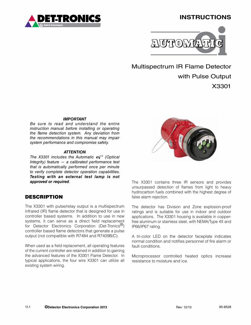
DESCRIPTION
The X3301 with pulse/relay output is a multispectrum infrared (IR) flame detector that is designed for use in controller based systems. In addition to use in new systems, it can serve as a direct field replacement for Detector Electronics Corporation (Det-Tronics®) controller based flame detectors that generate a pulse output (not compatible with R7484 and R7409B/C).
When used as a field replacement, all operating features of the current controller are retained in addition to gaining the advanced features of the X3301 Flame Detector. In typical applications, the four wire X3301 can utilize all existing system wiring.
The X3301 contains three IR sensors and provides unsurpassed detection of flames from light to heavy hydrocarbon fuels combined with the highest degree of false alarm rejection.
The detector has Division and Zone explosion-proof ratings and is suitable for use in indoor and outdoor applications. The X3301 housing is available in copper-free aluminum or stainless steel, with NEMA/Type 4X and IP66/IP67 rating.
A tri-color LED on the detector faceplate indicates normal condition and notifies personnel of fire alarm or fault conditions.
Microprocessor controlled heated optics increase resistance to moisture and ice.
©Detector Electronics Corporation 2013 Rev: 12/13
95-852811.1 2
OUTpUTS
Relays
The detector is furnished with fire and fault relays. The relays are rated 5 amperes at 30 Vdc.
The Fire Alarm relay has redundant terminals and normally open / normally closed contacts, normally de-energized operation, and latching or non-latching operation.
The Fault relay has redundant terminals and normally open contacts, normally energized operation, and latching or non-latching operation.
An alarm condition will normally over-ride a fault condition, unless the nature of the fault condition impairs the ability of the detector to generate or maintain an alarm output, i.e. loss of operating power.
LED
A tri-color LED on the detector faceplate indicates normal condition and notifies personnel of fire alarm or fault conditions. Table 1 indicates the condition of the LED for each status.
oi (OpTICaL INTEgRITy)
automatic oiThe X3301 includes the Automatic oi feature — a calibrated performance test that is automatically performed once per minute to verify complete detector operation capabilities. No testing with an external test lamp is required. The detector automatically performs the same test that a maintenance person with a test lamp would perform — once every minute. However, a successful Automatic oi test does not produce an alarm condition.
The X3301 signals a fault condition when less than half of the detection range remains. This is indicated by the Fault output and is evident by the yellow color of the LED on the face of the detector. The oi fault condition is self-clearing if the optical contamination is temporary. If the contamination is not automatically cleared and the oi fault remains, the detector may require cleaning or service. See the “Troubleshooting” section for further information.
Magnetic oi / Manual oi
CaUtIonThese tests require disabling of all extinguishing devices to avoid release resulting from a successful test.
The detector incorporates both Magnetic oi (Mag oi) and Manual oi (Man oi) test capabilities. These tests provide pulses (80 to 100 CPS) to the controller (R7404 or R7494) when the detector is not in fault. If the test is successful, the controller indicates a fire and the appropriate zone output is active.
NOTEIf the detector is in a fault condition, a successful Mag oi or Man oi test cannot be performed.
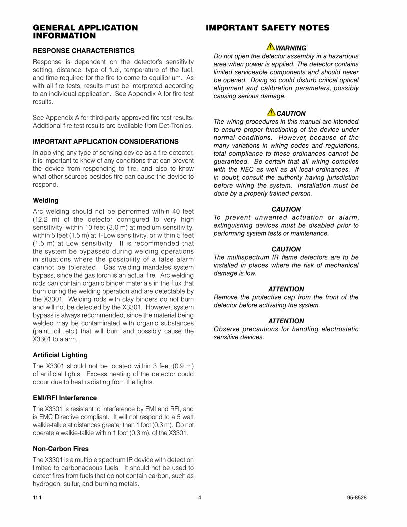
The Mag oi test is initiated by placing a magnet at the location marked “MAG OI” on the outside of the detector (see Figure 2). This action causes the detector to immediately send pulses to the controller. Controller response is as follows:
• The Zone LED blinks.
• The digital display indicates which Zone is in alarm.
• The status indicator shows “6” (fire).
ImportantMag oi can be performed with the controller’s (R7404/R7494) keylock switch in either the NORMAL or TEST position. In NORMAL, the controller goes into alarm and activates its outputs. If no controller alarm output is desired, place the keylock switch in the TEST position before touching the magnet to the outside of the detector. Man oi operates only with the keylock switch in the TEST position.
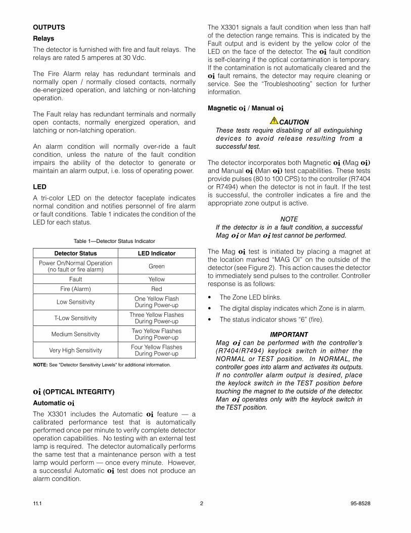
Table 1—Detector Status Indicator
Detector Status LED Indicator
Power On/Normal Operation(no fault or fire alarm) Green
Fault Yellow
Fire (Alarm) Red
Low Sensitivity One Yellow FlashDuring Power-up
T-Low Sensitivity Three Yellow FlashesDuring Power-up
Medium Sensitivity Two Yellow FlashesDuring Power-up
Very High Sensitivity Four Yellow FlashesDuring Power-up
NOTE: See "Detector Sensitivity Levels" for additional information .
3 95-852811.1
During the entire test, the detector gives no indication of alarm.
To reset the controller status and alarms, place the keylock switch in RESET. Return the keylock switch to NORMAL when testing is complete.
The Man oi test is nearly identical to the Mag oi test, except for the manner in which the test is initiated:
• Place the keylock switch on the controller (R7404/R7494) in the TEST position.
• Press the SELECT button to select the appropriate detector for test.
• Press the TEST/ACCEPT button to initiate the test.
Controller and detector responses are identical to the Mag oi test described above.
To reset the controller status and alarms, place the keylock switch in RESET. Return the keylock switch to NORMAL when testing is complete.
NOTERefer to Appendix A for FM verification of the oi function.
COMMUNICaTION
The X3301 is furnished with an RS-485 interface for communicating status and other information with external devices. The RS-485 supports MODBUS protocol, with the detector configured as a slave device.
DaTa LOggINg
Data logging capability is also provided. Status conditions such as normal, power down, general and oi faults, fire alarm, time and temperature are recorded. Each event is time and date stamped, along with the temperature and input voltage. Event data is stored in non-volatile memory when the event becomes active, and again when the status changes. Data is accessible using the Inspector Connector accessory or RS-485.
INTEgRaL WIRINg COMpaRTMENT
All external wiring to the device is connected within the integral junction box. The detector is furnished with four conduit entries, with either 3/4 inch NPT or M25 threads.
DETECTOR SENSITIvITy LEvELS
There are four factory configured sensitivity levels available for the X3301 Flame Detector:
Very High, Medium, Low and T-Low.
The following criteria should be considered when choosing a sensitivity level for the intended application:
• Detector placement
• Speed of response based on fuel type and fire size (see Appendix A for response times)
• Distance between the hazard and the flame detector
Recommended sensitivity guidelines are as follows:
Very High: Offshore, Warehousing
Medium: General Duty, Compressors
Low: Offshore, close proximity/high IR backgrounds
T-Low: Turbine Enclosures
Additional information on X3301 Flame Detector performance results and sensitivities can be found in Appendix A, the FM Approval and Performance Report.
Consult the factory with any questions on how to choose the optimum sensitivity level for the intended application.
95-852811.1 4
GENERal aPPlICaTION INfORmaTION
RESpONSE ChaRaCTERISTICS
Response is dependent on the detector’s sensitivity setting, distance, type of fuel, temperature of the fuel, and time required for the fire to come to equilibrium. As with all fire tests, results must be interpreted according to an individual application. See Appendix A for fire test results.
See Appendix A for third-party approved fire test results. Additional fire test results are available from Det-Tronics.
IMpORTaNT appLICaTION CONSIDERaTIONS
In applying any type of sensing device as a fire detector, it is important to know of any conditions that can prevent the device from responding to fire, and also to know what other sources besides fire can cause the device to respond.
Welding
Arc welding should not be performed within 40 feet (12.2 m) of the detector configured to very high sensitivity, within 10 feet (3.0 m) at medium sensitivity, within 5 feet (1.5 m) at T-Low sensitivity, or within 5 feet (1.5 m) at Low sensitivity. It is recommended that the system be bypassed during welding operations in situations where the possibility of a false alarm cannot be tolerated. Gas welding mandates system bypass, since the gas torch is an actual fire. Arc welding rods can contain organic binder materials in the flux that burn during the welding operation and are detectable by the X3301. Welding rods with clay binders do not burn and will not be detected by the X3301. However, system bypass is always recommended, since the material being welded may be contaminated with organic substances (paint, oil, etc.) that will burn and possibly cause the X3301 to alarm.
artificial Lighting
The X3301 should not be located within 3 feet (0.9 m) of artificial lights. Excess heating of the detector could occur due to heat radiating from the lights.
EMI/RFI Interference
The X3301 is resistant to interference by EMI and RFI, and is EMC Directive compliant. It will not respond to a 5 watt walkie-talkie at distances greater than 1 foot (0.3 m). Do not operate a walkie-talkie within 1 foot (0.3 m). of the X3301.
Non-Carbon Fires
The X3301 is a multiple spectrum IR device with detection limited to carbonaceous fuels. It should not be used to detect fires from fuels that do not contain carbon, such as hydrogen, sulfur, and burning metals.
ImPORTaNT SafETy NOTES
WarnIngDo not open the detector assembly in a hazardous area when power is applied. The detector contains limited serviceable components and should never be opened. Doing so could disturb critical optical alignment and calibration parameters, possibly causing serious damage.
CaUtIonThe wiring procedures in this manual are intended to ensure proper functioning of the device under normal conditions. However, because of the many variations in wiring codes and regulations, total compliance to these ordinances cannot be guaranteed. Be certain that all wiring complies with the NEC as well as all local ordinances. If in doubt, consult the authority having jurisdiction before wiring the system. Installation must be done by a properly trained person.
CaUtIonTo prevent unwanted actuation or alarm, extinguishing devices must be disabled prior to performing system tests or maintenance.
CaUtIonThe multispectrum IR flame detectors are to be installed in places where the risk of mechanical damage is low.
attEntIonRemove the protective cap from the front of the detector before activating the system.
attEntIonObserve precautions for handling electrostatic sensitive devices.
5 95-852811.1
INSTallaTION
NOTEThe recommended lubricant for threads and O-rings is a silicone free grease (p/n 005003-001) available from Det-Tronics. Under no circumstances should a lubricant containing silicone be used.
DETECTOR pOSITIONINg
Detectors should be positioned to provide the best unobstructed view of the area to be protected. The following factors should also be taken into consideration:
• Identify all high risk fire ignition sources.
• Be sure that enough detectors are used to adequately cover the hazardous area.
• Be sure that the unit is easily accessible for cleaning and other periodic servicing.
• Verify that all detectors in the system are properly located and positioned so that any fire hazards are within both the Field of View (FOV) and detection range of the detector. The Q1201C Laser Aimer is recommended for establishing the detector’s FOV. Refer to Appendix A for specific information regarding detector range and FOV.
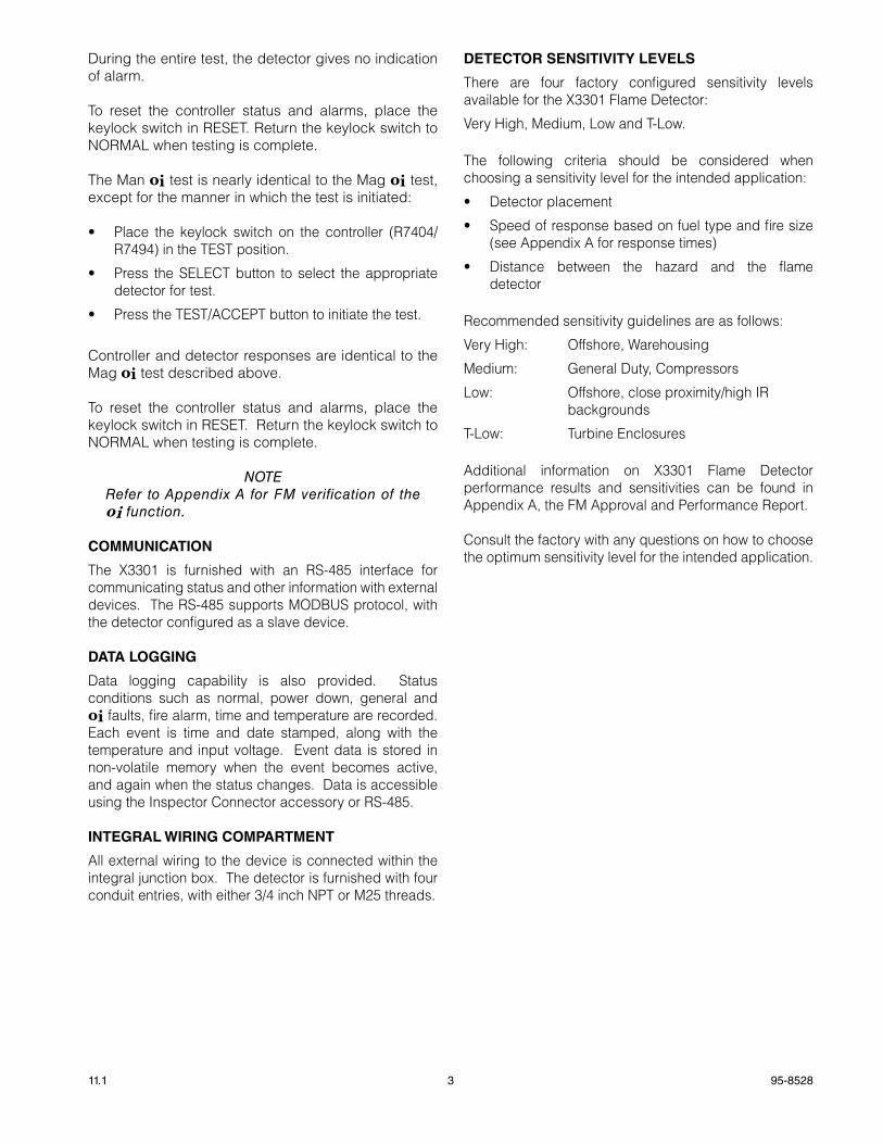
• The detector should be aimed downward at least 10 to 20 degrees to allow lens openings to drain. See Figure 1. The detector should be positioned so that its FOv does not cover areas outside the hazardous area. This will minimize the possibility of false alarms caused by activities outside the area requiring protection.
• The detector must be mounted on a rigid surface in a low vibration area.
• Dense fog, rain or ice can absorb IR radiation and reduce the sensitivity of the detector. To ensure optimum performance, be certain that the internal optical heater is enabled on detectors that are used in applications where snow, ice, and/condensation are likely to occur.
• Although IR detectors are less affected by smoke than other detectors, the X3301 should not be placed where rising combustion products can obscure its vision. If smoke is expected before fire, smoke or other alternative detectors should be used in conjunction with the X3301. For indoor applications, if dense smoke is expected to accumulate at the onset of a fire, mount the detector on a side wall at least a few feet (approximately 1 meter) down from the ceiling.
• If possible, fire tests can be conducted to verify correct detector positioning and coverage.
• For ATEX installations, the X3301 Flame Detector housing must be electrically connected to earth ground.
DETECTOR ORIENTaTION
Refer to Figure 2 and ensure that the oi plate will be oriented as shown when the X3301 is mounted and sighted. This will ensure proper operation of the oi system and will also minimize the accumulation of moisture and contaminants between the oi plate and the viewing windows.
ImportantIf removed, the oi plate must be securely tightened to ensure proper operation of the oi system (40 oz./inches [28.2 N .cm] recommended).
figure 1—Detector Orientation Relative to Horizon
CENTER AXIS OF DETECTOR FIELD OF VIEW
CENTER AXIS OF DETECTOR FIELD OF VIEW
INCORRECT
CORRECT
NOTE: DETECTOR MUST ALWAYS BE AIMED DOWNWARD AT LEAST 10 TO 20 DEGREES.
D1974
VIEWING WINDOW (3)
oi PLATE
PLACE MAGNETHERE TO INITIATE
MAGNETIC oi
oi MAGNET
DETECTORSTATUS INDICATOR
F2068
figure 2—front View of the X3301
95-852811.1 6
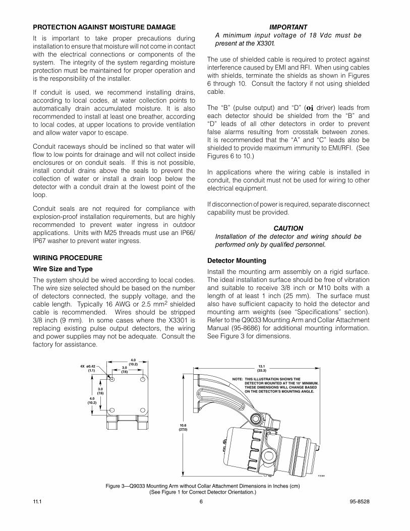
figure 3—Q9033 mounting arm without Collar attachment Dimensions in Inches (cm)(See figure 1 for Correct Detector Orientation .)
pROTECTION agaINST MOISTURE DaMagE
It is important to take proper precautions during installation to ensure that moisture will not come in contact with the electrical connections or components of the system. The integrity of the system regarding moisture protection must be maintained for proper operation and is the responsibility of the installer.
If conduit is used, we recommend installing drains, according to local codes, at water collection points to automatically drain accumulated moisture. It is also recommended to install at least one breather, according to local codes, at upper locations to provide ventilation and allow water vapor to escape.
Conduit raceways should be inclined so that water will flow to low points for drainage and will not collect inside enclosures or on conduit seals. If this is not possible, install conduit drains above the seals to prevent the collection of water or install a drain loop below the detector with a conduit drain at the lowest point of the loop.
Conduit seals are not required for compliance with explosion-proof installation requirements, but are highly recommended to prevent water ingress in outdoor applications. Units with M25 threads must use an IP66/IP67 washer to prevent water ingress.
WIRINg pROCEDURE
Wire Size and Type
The system should be wired according to local codes. The wire size selected should be based on the number of detectors connected, the supply voltage, and the cable length. Typically 16 AWG or 2.5 mm2 shielded cable is recommended. Wires should be stripped 3/8 inch (9 mm). In some cases where the X3301 is replacing existing pulse output detectors, the wiring and power supplies may not be adequate. Consult the factory for assistance.
ImportantA minimum input voltage of 18 Vdc must be present at the X3301.
The use of shielded cable is required to protect against interference caused by EMI and RFI. When using cables with shields, terminate the shields as shown in Figures 6 through 10. Consult the factory if not using shielded cable.
The “B” (pulse output) and “D” (oi driver) leads from each detector should be shielded from the “B” and “D” leads of all other detectors in order to prevent false alarms resulting from crosstalk between zones. It is recommended that the “A” and “C” leads also be shielded to provide maximum immunity to EMI/RFI. (See Figures 6 to 10.)
In applications where the wiring cable is installed in conduit, the conduit must not be used for wiring to other electrical equipment.
If disconnection of power is required, separate disconnect capability must be provided.
CaUtIonInstallation of the detector and wiring should be performed only by qualified personnel.
Detector Mounting
Install the mounting arm assembly on a rigid surface. The ideal installation surface should be free of vibration and suitable to receive 3/8 inch or M10 bolts with a length of at least 1 inch (25 mm). The surface must also have sufficient capacity to hold the detector and mounting arm weights (see “Specifications” section). Refer to the Q9033 Mounting Arm and Collar Attachment Manual (95-8686) for additional mounting information. See Figure 3 for dimensions.
13.1(33.3)
10.6(27.0)
4.0(10.2)
4.0(10.2)
3.0(7.6)
3.0(7.6)
4X ø0.42 (1.1)
F2069
NOTE: THIS ILLUSTRATION SHOWS THE DETECTOR MOUNTED AT THE 10° MINIMUM. THESE DIMENSIONS WILL CHANGE BASED ON THE DETECTOR’S MOUNTING ANGLE.
7 95-852811.1
Detector Wiring
ImportantIf installing an X3301 in place of an existing detector, be sure to move the “A” Lead (detector power) at the controller from the +290 Vdc source to the +24 Vdc source. Do not apply 290 Vdc to the X3301.
1. Make field connections following local ordinances and guidelines in this manual.
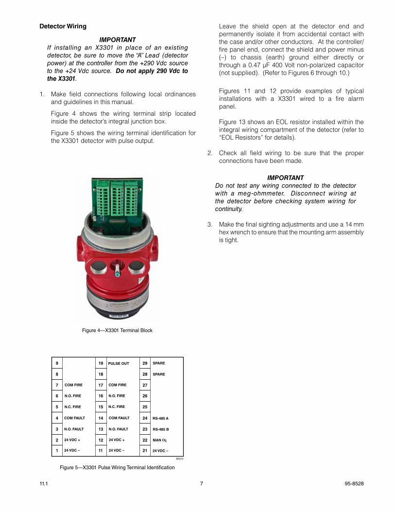
Figure 4 shows the wiring terminal strip located inside the detector’s integral junction box.
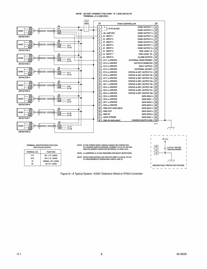
Figure 5 shows the wiring terminal identification for the X3301 detector with pulse output.
Leave the shield open at the detector end and permanently isolate it from accidental contact with the case and/or other conductors. At the controller/fire panel end, connect the shield and power minus (–) to chassis (earth) ground either directly or through a 0.47 µF 400 Volt non-polarized capacitor (not supplied). (Refer to Figures 6 through 10.)
Figures 11 and 12 provide examples of typical
installations with a X3301 wired to a fire alarm panel.
Figure 13 shows an EOL resistor installed within the
integral wiring compartment of the detector (refer to “EOL Resistors” for details).
2. Check all field wiring to be sure that the proper
connections have been made.
ImportantDo not test any wiring connected to the detector with a meg-ohmmeter. Disconnect wiring at the detector before checking system wiring for continuity.
3. Make the final sighting adjustments and use a 14 mm hex wrench to ensure that the mounting arm assembly is tight.
9
8
7
6
5
4
3
2
1
19
18
17
16
15
14
13
12
11
PULSE OUT
COM FIRE COM FIRE
N.O. FIRE N.O. FIRE
N.C. FIRE N.C. FIRE
COM FAULT COM FAULT
N.O. FAULT N.O. FAULT
24 VDC + 24 VDC +
24 VDC – 24 VDC –24 VDC –
29
28
27
26
25
24
23
22
21
SPARE
SPARE
RS-485 A
RS-485 B
MAN Oi
B2070
figure 5—X3301 Pulse Wiring Terminal Identification
figure 4—X3301 Terminal Block
95-852811.1 8
1
2
3
4
5
6
7
8
9
10
11
12
13
14
15
16
17
18
19
20
21
22
23
24
25
26
27
28
29
30
31
32
+ – (A) +290 VDC
B - INPUT 1
B - INPUT 2
B - INPUT 3
B - INPUT 4
B - INPUT 5
B - INPUT 6
B - INPUT 7
B - INPUT 8
D1-1 oi DRIVER
D1-2 oi DRIVER
D1-3 oi DRIVER
D1-4 oi DRIVER
D1-5 oi DRIVER
D1-6 oi DRIVER
D1-7 oi DRIVER
D1-8 oi DRIVER
D2-1 oi DRIVER
D2-2 oi DRIVER
D2-3 oi DRIVER
D2-4 oi DRIVER
D2-5 oi DRIVER
D2-6 oi DRIVER
D2-7 oi DRIVER
D2-8 oi DRIVER
DMA OUT AVAILABLE
DMA OUT
DMA IN
DATA STROBE
33
34
35
36
37
38
39
40
41
42
43
44
45
46
47
48
49
50
51
52
53
54
55
56
57
58
59
60
61
62
63
64
ZONE OUTPUT 1
ZONE OUTPUT 2
ZONE OUTPUT 3
ZONE OUTPUT 4
ZONE OUTPUT 5
ZONE OUTPUT 6
ZONE OUTPUT 7
ZONE OUTPUT 8
FIRE LOGIC “A”
FIRE LOGIC “B”
ALARM OUTPUT
EXTERNAL RESET/INHIBIT
OUTPUTS INHIBITED
FAULT OUTPUT
EXTERNAL ACCEPT
STATUS & DET. OUTPUT S1
STATUS & DET. OUTPUT S2
STATUS & DET. OUTPUT S3
STATUS & DET. OUTPUT S4
STATUS & DET. OUTPUT S5
STATUS & DET. OUTPUT S6
STATUS & DET. OUTPUT S7
STATUS & DET. OUTPUT S8
DATA BUS 0
DATA BUS 1
DATA BUS 2
DATA BUS 3
DATA BUS 4
DATA BUS 5
DATA BUS 6
DATA BUS 7
CHASSIS (EARTH) GNDDMA IN AVAILABLE
J1-7J1-15
J1-5J1-13
J1-6J1-14
J1-8J1-16
J1-9J1-17
J1-10J1-18
J1-11J1-19
J2R7404 CONTROLLERJ1
10 TO 38 VDC}#2#1
#19#22
X3301
DETECTOR 1
#2#1#19#22
#2#1
#19#22
X3301
DETECTOR 2
#2#1#19#22
#2#1
#19#22
X3301
DETECTOR 3
#2#1#19#22
#2#1
#19#22
X3301
DETECTOR 4
#2#1#19#22
#2#1
#19#22
X3301
DETECTOR 5
#2#1#19#22
#2#1
#19#22
X3301
DETECTOR 6
#2#1#19#22
#2#1
#19#22
X3301
DETECTOR 7
#2#1#19#22
#2#1
#19#22
X3301
DETECTOR 8
#2#1#19#22
B2071
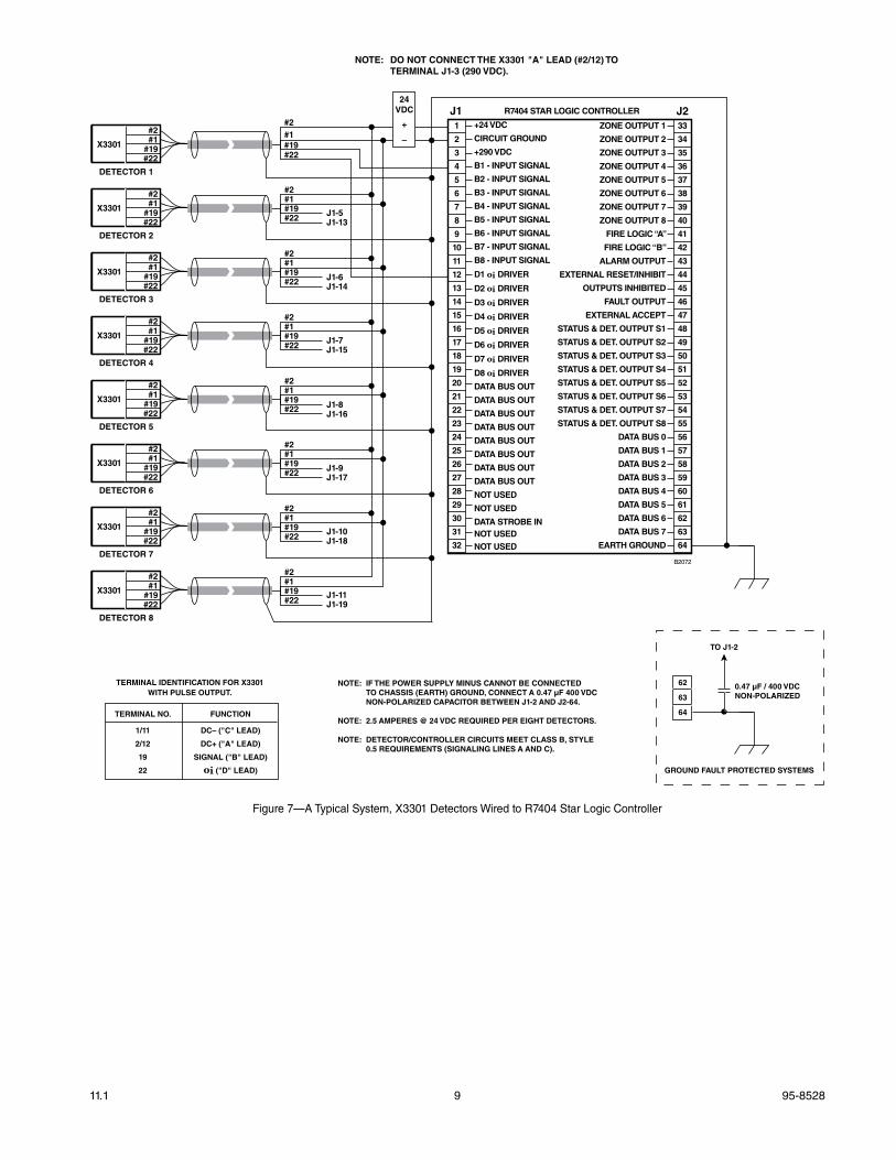
NOTE: IF THE POWER SUPPLY MINUS CANNOT BE CONNECTED TO CHASSIS (EARTH) GROUND, CONNECT A 0.47 µF 400 VDC NON-POLARIZED CAPACITOR BETWEEN J1-2 AND J2-64.
NOTE: 2.5 AMPERES @ 24 VDC REQUIRED PER EIGHT DETECTORS.
NOTE: DETECTOR/CONTROLLER CIRCUITS MEET CLASS B, STYLE 0.5 REQUIREMENTS (SIGNALING LINES A AND C).
24VDC
+
–
62
63
64
TO J1-2
0.47 µF / 400 VDCNON-POLARIZED
GROUND FAULT PROTECTED SYSTEMS
TERMINAL NO. FUNCTION
1/11 DC– ("C" LEAD)
2/12 DC+ ("A" LEAD)
19 SIGNAL ("B" LEAD)
22 oi ("D" LEAD)
TERMINAL IDENTIFICATION FOR X3301WITH PULSE OUTPUT.
NOTE: DO NOT CONNECT THE X3301 "A" LEAD (#2/12) TO TERMINAL J1-3 (290 VDC).
figure 6—a Typical System, X3301 Detectors Wired to R7404 Controller
9 95-852811.1
J1-7J1-15
J1-5J1-13
J1-6J1-14
J1-8J1-16
J1-9J1-17
J1-10J1-18
J1-11J1-19
J2J1
#2#1
#19#22
X3301
DETECTOR 1
#2#1#19#22
#2#1
#19#22
X3301
DETECTOR 2
#2#1#19#22
#2#1
#19#22
X3301
DETECTOR 3
#2#1#19#22
#2#1
#19#22
X3301
DETECTOR 4
#2#1#19#22
#2#1
#19#22
X3301
DETECTOR 5
#2#1#19#22
#2#1
#19#22
X3301
DETECTOR 6
#2#1#19#22
#2#1
#19#22
X3301
DETECTOR 7
#2#1#19#22
#2#1
#19#22
X3301
DETECTOR 8
#2#1#19#22
1
2
3
4
5
6
7
8
9
10
11
12
13
14
15
16
17
18
19
20
21
22
23
24
25
26
27
28
29
30
31
32
+24 VDC
CIRCUIT GROUND
+290 VDC
B1 - INPUT SIGNAL
B2 - INPUT SIGNAL
B3 - INPUT SIGNAL
B4 - INPUT SIGNAL
B5 - INPUT SIGNAL
B6 - INPUT SIGNAL
B7 - INPUT SIGNAL
B8 - INPUT SIGNAL
D1 oi DRIVER
D2 oi DRIVER
D3 oi DRIVER
D4 oi DRIVER
D5 oi DRIVER
D6 oi DRIVER
D7 oi DRIVER
D8 oi DRIVER
DATA BUS OUT
DATA BUS OUT
DATA BUS OUT
DATA BUS OUT
DATA BUS OUT
DATA BUS OUT
DATA BUS OUT
DATA BUS OUT
NOT USED
NOT USED
DATA STROBE INNOT USEDNOT USED
33
34
35
36
37
38
39
40
41
42
43
44
45
46
47
48
49
50
51
52
53
54
55
56
57
58
59
60
61
62
63
64
ZONE OUTPUT 1
ZONE OUTPUT 2
ZONE OUTPUT 3
ZONE OUTPUT 4
ZONE OUTPUT 5
ZONE OUTPUT 6
ZONE OUTPUT 7
ZONE OUTPUT 8
FIRE LOGIC “A”
FIRE LOGIC “B”
ALARM OUTPUT
EXTERNAL RESET/INHIBIT
OUTPUTS INHIBITED
FAULT OUTPUT
EXTERNAL ACCEPT
STATUS & DET. OUTPUT S1
STATUS & DET. OUTPUT S2
STATUS & DET. OUTPUT S3
STATUS & DET. OUTPUT S4
STATUS & DET. OUTPUT S5
STATUS & DET. OUTPUT S6
STATUS & DET. OUTPUT S7
STATUS & DET. OUTPUT S8
DATA BUS 0
DATA BUS 1
DATA BUS 2
DATA BUS 3
DATA BUS 4
DATA BUS 5
DATA BUS 6
DATA BUS 7
EARTH GROUND
R7404 STAR LOGIC CONTROLLER
B2072
NOTE: IF THE POWER SUPPLY MINUS CANNOT BE CONNECTED TO CHASSIS (EARTH) GROUND, CONNECT A 0.47 µF 400 VDC NON-POLARIZED CAPACITOR BETWEEN J1-2 AND J2-64.
NOTE: 2.5 AMPERES @ 24 VDC REQUIRED PER EIGHT DETECTORS.
NOTE: DETECTOR/CONTROLLER CIRCUITS MEET CLASS B, STYLE 0.5 REQUIREMENTS (SIGNALING LINES A AND C).
24VDC
+
–
62
63
64
TO J1-2
0.47 µF / 400 VDCNON-POLARIZED
GROUND FAULT PROTECTED SYSTEMS
NOTE: DO NOT CONNECT THE X3301 "A" LEAD (#2/12) TO TERMINAL J1-3 (290 VDC).
TERMINAL NO. FUNCTION
1/11 DC– ("C" LEAD)
2/12 DC+ ("A" LEAD)
19 SIGNAL ("B" LEAD)
22 oi ("D" LEAD)
TERMINAL IDENTIFICATION FOR X3301WITH PULSE OUTPUT.
figure 7—a Typical System, X3301 Detectors Wired to R7404 Star Logic Controller
95-852811.1 10
J1-7J1-15
J1-5J1-13
J1-6J1-14
J1-8J1-16
J1-9J1-17
J1-10J1-18
J1-11J1-19
J2J1
#2#1
#19#22
X3301
DETECTOR 1
#2#1#19#22
#2#1
#19#22
X3301
DETECTOR 2
#2#1#19#22
#2#1
#19#22
X3301
DETECTOR 3
#2#1#19#22
#2#1
#19#22
X3301
DETECTOR 4
#2#1#19#22
#2#1
#19#22
X3301
DETECTOR 5
#2#1#19#22
#2#1
#19#22
X3301
DETECTOR 6
#2#1#19#22
#2#1
#19#22
X3301
DETECTOR 7
#2#1#19#22
#2#1
#19#22
X3301
DETECTOR 8
#2#1#19#22
1
2
3
4
5
6
7
8
9
10
11
12
13
14
15
16
17
18
19
20
21
22
23
24
25
26
27
28
29
30
31
32
+24 VDC
CIRCUIT GROUND
+24 VDC
B1 - INPUT SIGNAL
B2 - INPUT SIGNAL
B3 - INPUT SIGNAL
B4 - INPUT SIGNAL
B5 - INPUT SIGNAL
B6 - INPUT SIGNAL
B7 - INPUT SIGNAL
B8 - INPUT SIGNAL
D1 oi DRIVER
D2 oi DRIVER
D3 oi DRIVER
D4 oi DRIVER
D5 oi DRIVER
D6 oi DRIVER
D7 oi DRIVER
D8 oi DRIVER
DATA BUS OUT
DATA BUS OUT
DATA BUS OUT
DATA BUS OUT
DATA BUS OUT
DATA BUS OUT
DATA BUS OUT
DATA BUS OUT
NOT USED
NOT USED
DATA STROBE INNOT USEDNOT USED
33
34
35
36
37
38
39
40
41
42
43
44
45
46
47
48
49
50
51
52
53
54
55
56
57
58
59
60
61
62
63
64
ZONE OUTPUT 1
ZONE OUTPUT 2
ZONE OUTPUT 3
ZONE OUTPUT 4
ZONE OUTPUT 5
ZONE OUTPUT 6
ZONE OUTPUT 7
ZONE OUTPUT 8
FIRE LOGIC “A”
FIRE LOGIC “B”
ALARM OUTPUT
EXTERNAL RESET/INHIBIT
OUTPUTS INHIBITED
FAULT OUTPUT
EXTERNAL ACCEPT
STATUS & DET. OUTPUT S1
STATUS & DET. OUTPUT S2
STATUS & DET. OUTPUT S3
STATUS & DET. OUTPUT S4
STATUS & DET. OUTPUT S5
STATUS & DET. OUTPUT S6
STATUS & DET. OUTPUT S7
STATUS & DET. OUTPUT S8
DATA BUS 0
DATA BUS 1
DATA BUS 2
DATA BUS 3
DATA BUS 4
DATA BUS 5
DATA BUS 6
DATA BUS 7
EARTH GROUND
R7494 CONTROLLER
B2073
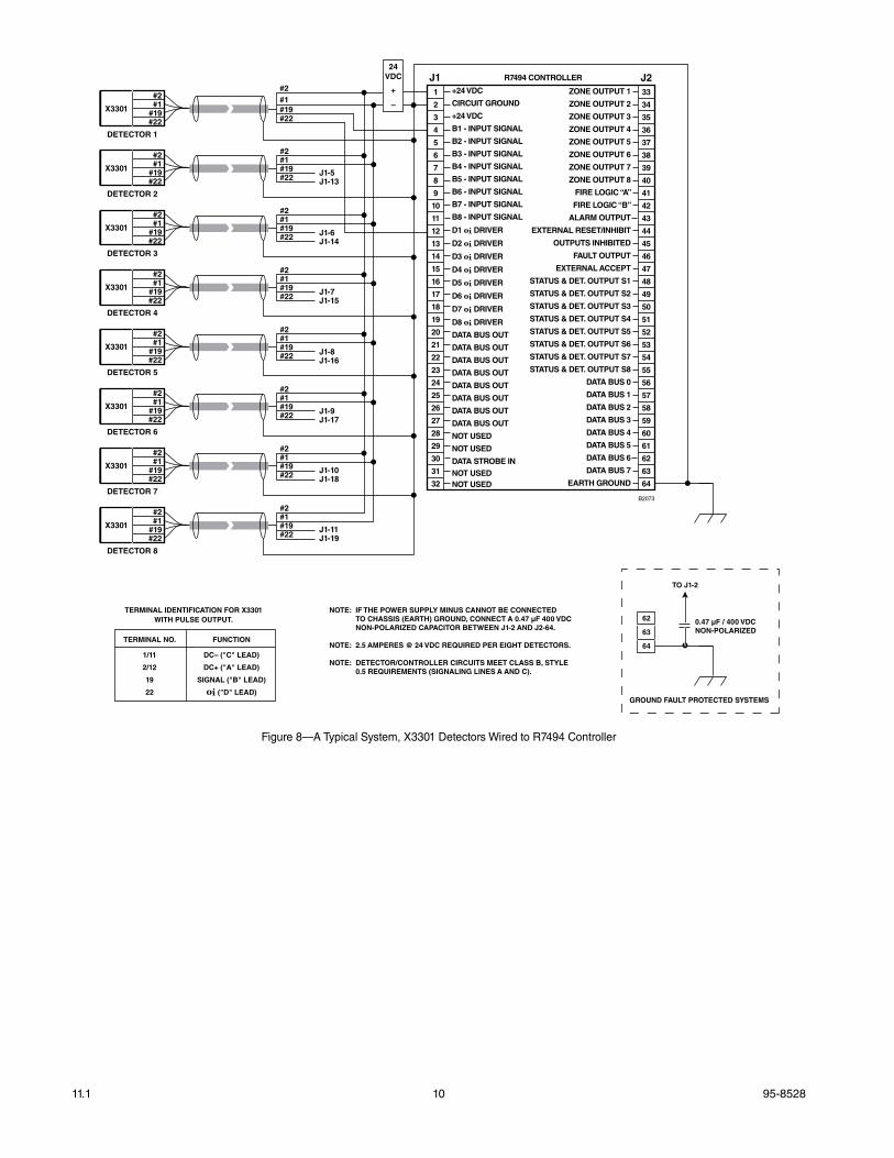
NOTE: IF THE POWER SUPPLY MINUS CANNOT BE CONNECTED TO CHASSIS (EARTH) GROUND, CONNECT A 0.47 µF 400 VDC NON-POLARIZED CAPACITOR BETWEEN J1-2 AND J2-64.
NOTE: 2.5 AMPERES @ 24 VDC REQUIRED PER EIGHT DETECTORS.
NOTE: DETECTOR/CONTROLLER CIRCUITS MEET CLASS B, STYLE 0.5 REQUIREMENTS (SIGNALING LINES A AND C).
62
63
64
TO J1-2
0.47 µF / 400 VDCNON-POLARIZED
GROUND FAULT PROTECTED SYSTEMS
24VDC
+
–
TERMINAL NO. FUNCTION
1/11 DC– ("C" LEAD)
2/12 DC+ ("A" LEAD)
19 SIGNAL ("B" LEAD)
22 oi ("D" LEAD)
TERMINAL IDENTIFICATION FOR X3301WITH PULSE OUTPUT.
figure 8—a Typical System, X3301 Detectors Wired to R7494 Controller
11 95-852811.1
1
2
3
4
5 31
32
33
34
35
36
37
38
39
40
41
42
43
44
45
46
47
49
50
+24 VDC
GROUND
D1
D2
D3
D4
D5
D6
D7
D8
B1
B2
B3
B4
B5
48 B6
B7
B8
J2-46J2-38
J2-44J2-36
J2-45J2-37
J2-47J2-39
J2-48J2-40
J2-49J2-41
J2-50J2-42
#2#1
#19#22
X3301
DETECTOR 1
#2#1#19#22
#2#1
#19#22
X3301
DETECTOR 2
#2#1#19#22
#2#1
#19#22
X3301
DETECTOR 3
#2#1#19#22
#2#1
#19#22
X3301
DETECTOR 4
#2#1#19#22
#2#1
#19#22
X3301
DETECTOR 5
#2#1#19#22
#2#1
#19#22
X3301
DETECTOR 6
#2#1#19#22
#2#1
#19#22
X3301
DETECTOR 7
#2#1#19#22
#2#1
#19#22
X3301
DETECTOR 8
#2#1#19#22
R7495 CONTROLLER(NOT FM APPROVED)
J1
J2
B2074
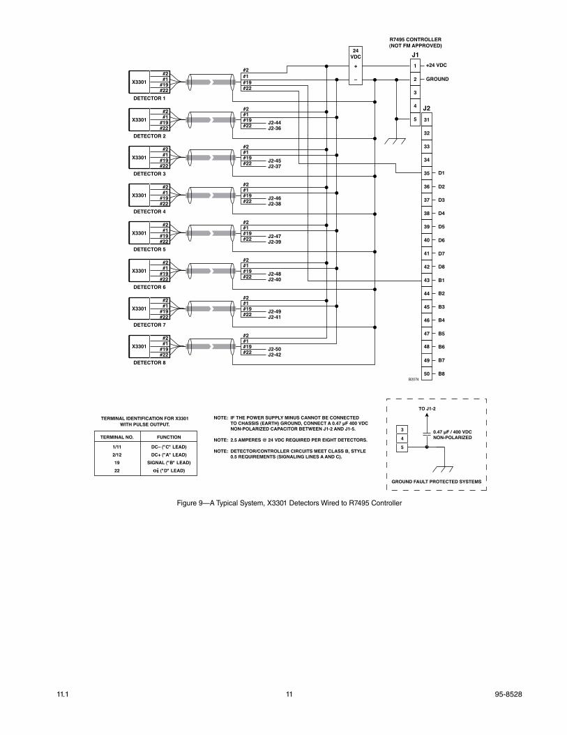
NOTE: IF THE POWER SUPPLY MINUS CANNOT BE CONNECTED TO CHASSIS (EARTH) GROUND, CONNECT A 0.47 µF 400 VDC NON-POLARIZED CAPACITOR BETWEEN J1-2 AND J1-5.
NOTE: 2.5 AMPERES @ 24 VDC REQUIRED PER EIGHT DETECTORS.
NOTE: DETECTOR/CONTROLLER CIRCUITS MEET CLASS B, STYLE 0.5 REQUIREMENTS (SIGNALING LINES A AND C).
3
4
5
TO J1-2
0.47 µF / 400 VDCNON-POLARIZED
GROUND FAULT PROTECTED SYSTEMS
24VDC
+
–
TERMINAL NO. FUNCTION
1/11 DC– ("C" LEAD) 2/12 DC+ ("A" LEAD) 19 SIGNAL ("B" LEAD) 22 oi ("D" LEAD)
TERMINAL IDENTIFICATION FOR X3301WITH PULSE OUTPUT.
figure 9—a Typical System, X3301 Detectors Wired to R7495 Controller
95-852811.1 12
1
2
3
4
5 31
32
33
34
35
36
37
38
39
40
41
42
43
44
45
46
47
49
50
+24 VDC
GROUND
D1
D2
D3
D4
D5
D6
D7
D8
B1
B2
B3
B4
B5
48 B6
B7
B8
J2-46J2-38
J2-44J2-36
J2-45J2-37
J2-47J2-39
J2-48J2-40
J2-49J2-41
J2-50J2-42
#2#1
#19#22
X3301
DETECTOR 1
#2#1#19#22
#2#1
#19#22
X3301
DETECTOR 2
#2#1#19#22
#2#1
#19#22
X3301
DETECTOR 3
#2#1#19#22
#2#1
#19#22
X3301
DETECTOR 4
#2#1#19#22
#2#1
#19#22
X3301
DETECTOR 5
#2#1#19#22
#2#1
#19#22
X3301
DETECTOR 6
#2#1#19#22
#2#1
#19#22
X3301
DETECTOR 7
#2#1#19#22
#2#1
#19#22
X3301
DETECTOR 8
#2#1#19#22
R7405 CONTROLLER (NOT FM APPROVED)
J1
J2
B2075
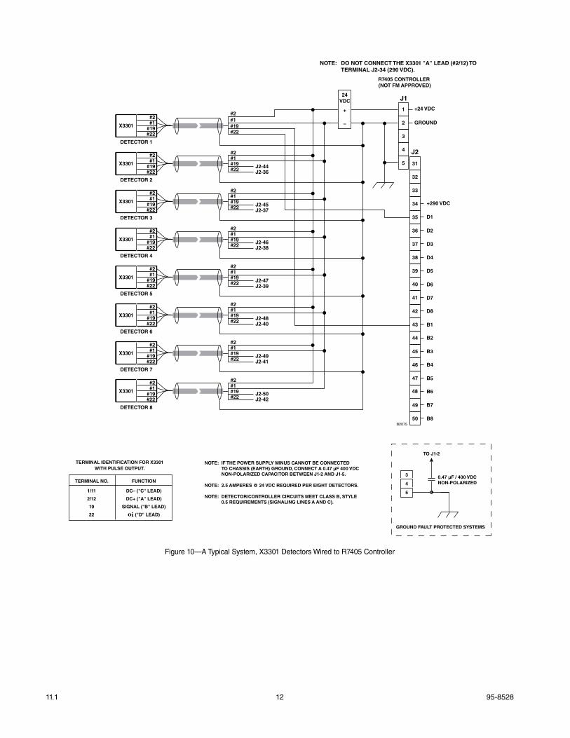
NOTE: IF THE POWER SUPPLY MINUS CANNOT BE CONNECTED TO CHASSIS (EARTH) GROUND, CONNECT A 0.47 µF 400 VDC NON-POLARIZED CAPACITOR BETWEEN J1-2 AND J1-5.
NOTE: 2.5 AMPERES @ 24 VDC REQUIRED PER EIGHT DETECTORS.
NOTE: DETECTOR/CONTROLLER CIRCUITS MEET CLASS B, STYLE 0.5 REQUIREMENTS (SIGNALING LINES A AND C).
+290 VDC
3
4
5
TO J1-2
0.47 µF / 400 VDCNON-POLARIZED
GROUND FAULT PROTECTED SYSTEMS
24VDC
+
–
NOTE: DO NOT CONNECT THE X3301 "A" LEAD (#2/12) TO TERMINAL J2-34 (290 VDC).
TERMINAL NO. FUNCTION
1/11 DC– ("C" LEAD)
2/12 DC+ ("A" LEAD)
19 SIGNAL ("B" LEAD)
22 oi ("D" LEAD)
TERMINAL IDENTIFICATION FOR X3301WITH PULSE OUTPUT.
figure 10—a Typical System, X3301 Detectors Wired to R7405 Controller
13 95-852811.1
B2062
FIRE ALARM PANEL
X3301 DETECTOR
ALARM
24 VDC
+
–
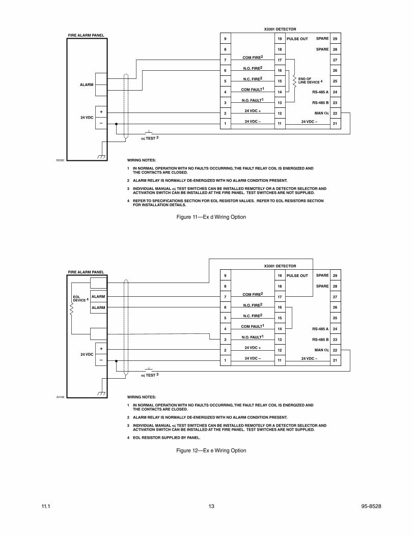
WIRING NOTES:
1 IN NORMAL OPERATION WITH NO FAULTS OCCURRING, THE FAULT RELAY COIL IS ENERGIZED AND THE CONTACTS ARE CLOSED.
2 ALARM RELAY IS NORMALLY DE-ENERGIZED WITH NO ALARM CONDITION PRESENT.
3 INDIVIDUAL MANUAL oi TEST SWITCHES CAN BE INSTALLED REMOTELY OR A DETECTOR SELECTOR AND ACTIVATION SWITCH CAN BE INSTALLED AT THE FIRE PANEL. TEST SWITCHES ARE NOT SUPPLIED.
4 REFER TO SPECIFICATIONS SECTION FOR EOL RESISTOR VALUES. REFER TO EOL RESISTORS SECTION FOR INSTALLATION DETAILS.
END OFLINE DEVICE 4
oi TEST 3
9
8
7
6
5
4
3
2
1
19
18
17
16
15
14
13
12
11
PULSE OUT
COM FIRE2
N.O. FIRE2
N.C. FIRE2
COM FAULT1
N.O. FAULT1
24 VDC +
24 VDC – 24 VDC –
29
28
27
26
25
24
23
22
21
SPARE
SPARE
RS-485 A
RS-485 B
MAN Oi
figure 11—Ex d Wiring Option
A2108
FIRE ALARM PANEL
X3301 DETECTOR
ALARM
ALARM
24 VDC
+
–
WIRING NOTES:
1 IN NORMAL OPERATION WITH NO FAULTS OCCURRING, THE FAULT RELAY COIL IS ENERGIZED AND THE CONTACTS ARE CLOSED.
2 ALARM RELAY IS NORMALLY DE-ENERGIZED WITH NO ALARM CONDITION PRESENT.
3 INDIVIDUAL MANUAL oi TEST SWITCHES CAN BE INSTALLED REMOTELY OR A DETECTOR SELECTOR AND ACTIVATION SWITCH CAN BE INSTALLED AT THE FIRE PANEL. TEST SWITCHES ARE NOT SUPPLIED.
4 EOL RESISTOR SUPPLIED BY PANEL.
EOLDEVICE 4
oi TEST 3
9
8
7
6
5
4
3
2
1
19
18
17
16
15
14
13
12
11
PULSE OUT
COM FIRE2
N.O. FIRE2
N.C. FIRE2
COM FAULT1
N.O. FAULT1
24 VDC +
24 VDC – 24 VDC –
29
28
27
26
25
24
23
22
21
SPARE
SPARE
RS-485 A
RS-485 B
MAN Oi
figure 12—Ex e Wiring Option
95-852811.1 14
EOL Resistors
To ensure that the insulating material of the wiring terminal block will not be affected by the heat generated by EOL resistors, observe the following guidelines when installing the resistors.
1. Required EOL resistor power rating must be 5 watts minimum.
NOTEEOL resistors must be ceramic, wirewound type, rated 5 watts minimum, with actual power dissipation not to exceed 2.5 watts. this applies to atEX/IEC installations only.
2. Resistor leads should be cut to a length of approximately 1 1/2 inches (40 mm).
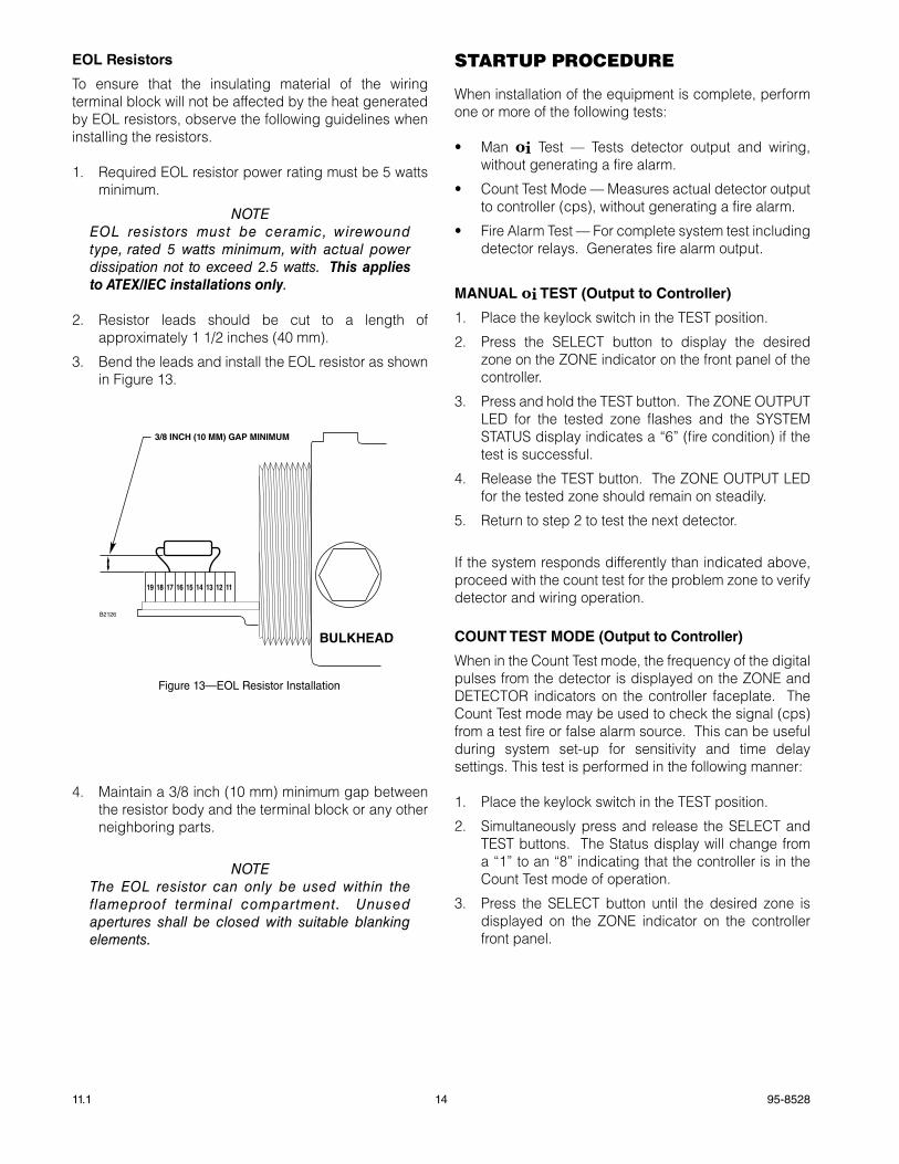
3. Bend the leads and install the EOL resistor as shown in Figure 13.
4. Maintain a 3/8 inch (10 mm) minimum gap between the resistor body and the terminal block or any other neighboring parts.
NOTEThe EOL resistor can only be used within the flameproof terminal compartment. Unused apertures shall be closed with suitable blanking elements.
STaRTUP PROCEDURE
When installation of the equipment is complete, perform one or more of the following tests:
• Man oi Test — Tests detector output and wiring, without generating a fire alarm.
• Count Test Mode — Measures actual detector output to controller (cps), without generating a fire alarm.
• Fire Alarm Test — For complete system test including detector relays. Generates fire alarm output.
MaNUaL oi TEST (Output to Controller)
1. Place the keylock switch in the TEST position.
2. Press the SELECT button to display the desired zone on the ZONE indicator on the front panel of the controller.
3. Press and hold the TEST button. The ZONE OUTPUT LED for the tested zone flashes and the SYSTEM STATUS display indicates a “6” (fire condition) if the test is successful.
4. Release the TEST button. The ZONE OUTPUT LED for the tested zone should remain on steadily.
5. Return to step 2 to test the next detector.
If the system responds differently than indicated above, proceed with the count test for the problem zone to verify detector and wiring operation.
COUNT TEST MODE (Output to Controller)
When in the Count Test mode, the frequency of the digital pulses from the detector is displayed on the ZONE and DETECTOR indicators on the controller faceplate. The Count Test mode may be used to check the signal (cps) from a test fire or false alarm source. This can be useful during system set-up for sensitivity and time delay settings. This test is performed in the following manner:
1. Place the keylock switch in the TEST position.
2. Simultaneously press and release the SELECT and TEST buttons. The Status display will change from a “1” to an “8” indicating that the controller is in the Count Test mode of operation.
3. Press the SELECT button until the desired zone is displayed on the ZONE indicator on the controller front panel.
3/8 INCH (10 MM) GAP MINIMUM
111213141516171819
B2126
BULKHEAD
figure 13—EOL Resistor Installation
15 95-852811.1
4. Press and hold the TEST button. The DETECTOR/ZONE display indicates the counts per second (cps) received from the detector. If the counts per second exceeds 99, the FIRE LOGIC LEDs are illuminated to indicate that the number shown on the display must be multiplied by 10. The normal reading for an oi test is 80 to 110 cps. For a live fire test, 270 - 330 cps will be generated.
A zero reading may indicate a dirty window, oi problem, faulty detector or defective wiring.
Release the Test button, the ZONE and DETECTOR display should drop to a reading of 0 to 1 counts per second.
FIRE aLaRM TEST (pulse Output to Fire alarm panel)
1. Disable any extinguishing equipment that is connected to the system.
2. Apply input power to the system.
3. Initiate a live fire test or a Mag oi test (see “Magnetic oi / Manual oi” under “Optical Integrity” in the Description section of this manual).
4. Repeat this test for all detectors in the system. If a unit fails the test, refer to the “Troubleshooting” section.
5. Verify that all detectors in the system are properly aimed at the area to be protected. (The Q1201C Laser Aimer is recommended for this purpose.)
6. Enable extinguishing equipment when the test is complete.
TROUBlESHOOTING
WarnIngThe sensor module (“front” half of the detector) contains no user serviceable components and should never be opened. The terminal compartment is the only part of the enclosure that should be opened by the user in the field.
1. Disable any extinguishing equipment that is connected to the unit.
2. Inspect the viewing windows for contamination and clean as necessary. The detector is relatively insensitive to airborne contaminants, however, thick deposits of ice, dirt, or oil will reduce sensitivity. (Refer to the “Maintenance” section for complete information regarding cleaning of the detector viewing windows.)
3. Check input power to the unit.
4. Check system and detector logs.
5. Turn off the input power to the detector and check all wiring for continuity. Important: Disconnect wiring at the detector before checking system wiring for continuity.
6. If all wiring checks out and cleaning of the oi plate/window did not correct the fault condition, check for high levels of background IR radiation by covering the detector with the factory supplied cover or aluminum foil. If the fault condition clears within 6 minutes or less, extreme background IR is present. Re-adjust the view of the detector away from the IR source or relocate the detector.
If none of these actions corrects the problem, return the detector to the factory for repair.
NOTEIt is highly recommended that a complete spare be kept on hand for field replacement to ensure continuous protection.
NOTEFor additional troubleshooting guides, refer to the Flame Inspector Monitor manual (95-8581).
95-852811.1 16
maINTENaNCE
ImportantPer iodic f lamepath inspect ions are not recommended, since the product is not intended to be serviced and provides proper ingress protection to eliminate potential deterioration of the flamepaths.
WarnIngThe sensor module (“front” half of the detector) contains no user serviceable components and should never be opened. The terminal compartment is the only part of the enclosure that should be opened by the user in the field.
To maintain maximum sensitivity and false alarm resistance, the viewing windows of the X3301 must be kept relatively clean. Refer to the following procedure for cleaning instructions.
CLEaNINg pROCEDURE
CaUtIonDisable any extinguishing equipment that is connected to the unit to prevent unwanted actuation.
To clean the windows and oi plate, use the window cleaner (p/n 001680-001) and a soft cloth, cotton swab, or tissue and refer to the following procedure:
1 . Disable any extinguishing equipment that is connected to the unit.
2. Since the X3301 is less affected by contamination than other detectors, removal of the oi plate is needed only under extreme conditions. In addition, it is not necessary to achieve perfect cleanliness, because IR is not significantly absorbed by slight films of oil and/or salt. If a fault condition is still indicated after cleaning, remove and clean the oi plate using the oi Plate Removal and Replacement procedure.
3. In all environments, clean all three viewing windows and reflector surfaces thoroughly. Use a cotton swab and the Det-Tronics window cleaning solution. Use Isopropyl alcohol for contaminations that the Det-Tronics window cleaning solution can not remove.
ImportantWhen used in extreme environments, the reflective surface of the detector oi plate may eventually deteriorate, resulting in reoccurring oi faults and the need for oi plate replacement.
oi pLaTE REMOvaL aND REpLaCEMENT
1 . Disable any extinguishing equipment that is connected to the unit.
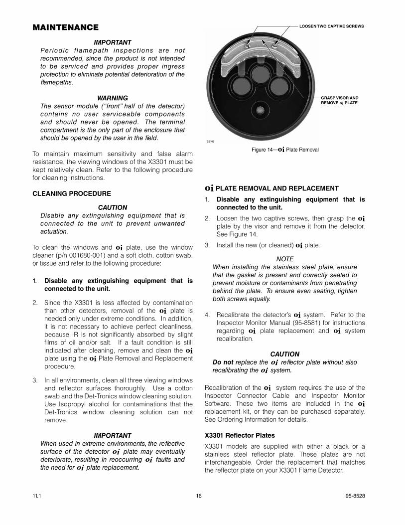
2. Loosen the two captive screws, then grasp the oi plate by the visor and remove it from the detector. See Figure 14.
3. Install the new (or cleaned) oi plate.
NOTEWhen installing the stainless steel plate, ensure that the gasket is present and correctly seated to prevent moisture or contaminants from penetrating behind the plate. To ensure even seating, tighten both screws equally.
4. Recalibrate the detector’s oi system. Refer to the Inspector Monitor Manual (95-8581) for instructions regarding oi plate replacement and oi system recalibration.
CaUtIonDo not replace the oi reflector plate without also recalibrating the oi system.
Recalibration of the oi system requires the use of the Inspector Connector Cable and Inspector Monitor Software. These two items are included in the oi replacement kit, or they can be purchased separately. See Ordering Information for details.
X3301 Reflector plates
X3301 models are supplied with either a black or a stainless steel reflector plate. These plates are not interchangeable. Order the replacement that matches the reflector plate on your X3301 Flame Detector.
figure 14—oi Plate Removal
LOOSEN TWO CAPTIVE SCREWS
GRASP VISOR ANDREMOVE oi PLATE
B2106
17 95-852811.1
pERIODIC ChECkOUT pROCEDURE
A checkout of the system using the Mag oi or Man oi feature should be performed on a regularly scheduled basis to ensure that the system is operating properly. To test the system, perform the “Manual oi Test,” “Count Test Mode” or “Fire Alarm Test” as described in the “Startup Procedure” section of this manual.
CLOCk BaTTERy
The real time clock has a backup battery that will operate the clock with no external power. Return the device to the factory for battery replacement if needed.
NOTEIf the backup battery is depleted, there is no effect on the operation of the flame detector, but the time stamping of the data log may be affected.
fEaTURES
• Long detection range to carbonaceous fires
• Unequaled false alarm rejection
• Responds to a fire in the presence of modulated blackbody radiation (i.e. heaters, ovens, turbines) without false alarm
• Pulse output for compatibility with controller based systems
• Microprocessor controlled heated optics for increased resistance to moisture and ice
• Automatic, manual or magnetic oi testing
• Easily replaceable oi plate
• Fire and fault relays
• Multiple sensitivity levels
• A tri-color LED on the detector faceplate indicates normal condition and notifies personnel of fire alarm or fault conditions
• Operates under adverse weather conditions and in dirty environments.
• Mounting arm allows easy sighting
• Integral wiring compartment for ease of installation
• Explosion-proof/flame-proof detector housing. Meets FM, CSA, ATEX Directive and CE certification requirements
• Class A wiring per NFPA-72 (Pulse output version is equivalent to class A when detectors are installed in a redundant configuration)
• 5 year warranty
• RFI and EMC Directive compliant
SPECIfICaTIONS
OPERaTING VOLTaGE— 24 Vdc nominal (18 Vdc minimum, 30 Vdc maximum). Maximum ripple is 2 volts peak-to-peak.
For CSA compliance, the power source must utilize a SELV (Safety Extra Low Voltage) or Class 2 style power supply.
POWER CONSUmPTION—Without heater: 4 watts at 24 Vdc nominal; 4.6 watts at 24 Vdc in alarm. 4.5 watts at 30 Vdc nominal; 5.9 watts at 30 Vdc in alarm.Heater only: 8 watts maximum.Total Power: 17 watts at 30 Vdc with EOL resistor installed and heater on maximum.EOL resistor must be ceramic, wirewound type, rated 5 watts minimum, with actual power dissipation not to exceed 2.5 watts.
POWER UP TImE—Fault indication clears after 0.5 second; device is ready to indicate an alarm condition after 30 seconds.
OUTPUT RELayS—Fire Alarm relay, Form C, 5 amperes at 30 Vdc: The Fire Alarm relay has redundant terminals and
normally open / normally closed contacts, normally de-energized operation, and latching or non-latching operation.
Fault relay, Form A, 5 amperes at 30 Vdc: The Fault relay has redundant terminals and normally
open contacts, normally energized operation, and latching or non-latching operation.
TEmPERaTURE RaNGE—Operating: –40°F to +167°F (–40°C to +75°C).Storage: –67°F to +185°F (–55°C to +85°C).Hazardous location ratings from –55°C to +125°C.
HUmIDITy RaNGE—0 to 95% relative humidity, can withstand 100% condensing humidity for short periods of time.
CONE Of VISION—The detector has a 90° cone of vision (horizontal) with the highest sensitivity lying along the central axis. Unlike conventional detectors, the X3301 provides full coverage at a minimum of 70% of the maximum detection distance.
Perfect cone of vision for methane fire detection — 100 feet on and off axis on “very high” setting.
Refer to Appendix A for FM Approved cone of vision data.
RESPONSE TImE—Typical response times are under 10 seconds. See Appendix A for actual response times.
95-852811.1 18
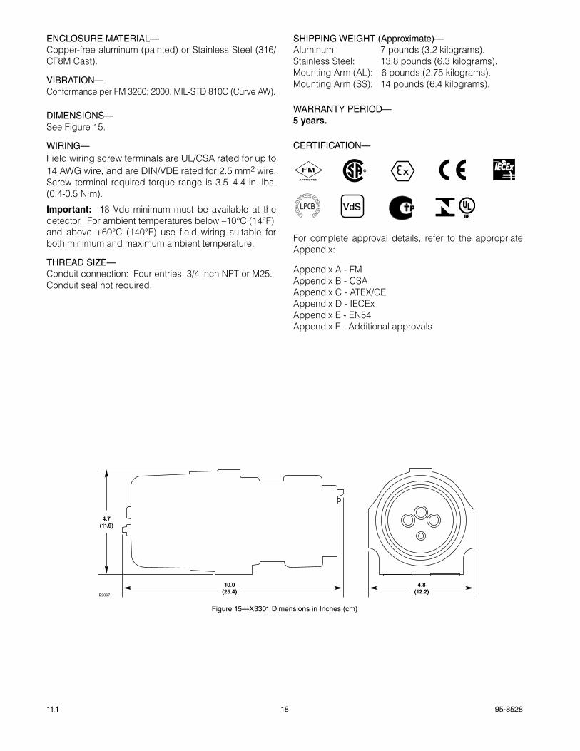
ENCLOSURE maTERIaL—Copper-free aluminum (painted) or Stainless Steel (316/CF8M Cast).
VIBRaTION—Conformance per FM 3260: 2000, MIL-STD 810C (Curve AW).
DImENSIONS—See Figure 15.
WIRING—Field wiring screw terminals are UL/CSA rated for up to 14 AWG wire, and are DIN/VDE rated for 2.5 mm2 wire. Screw terminal required torque range is 3.5–4.4 in.-lbs. (0.4-0.5 N·m).
Important: 18 Vdc minimum must be available at the detector. For ambient temperatures below –10°C (14°F)and above +60°C (140°F) use field wiring suitable for both minimum and maximum ambient temperature.
THREaD SIZE—Conduit connection: Four entries, 3/4 inch NPT or M25.Conduit seal not required.
SHIPPING WEIGHT (approximate)—Aluminum: 7 pounds (3.2 kilograms).Stainless Steel: 13.8 pounds (6.3 kilograms).Mounting Arm (AL): 6 pounds (2.75 kilograms).Mounting Arm (SS): 14 pounds (6.4 kilograms).
WaRRaNTy PERIOD—5 years.
CERTIfICaTION—
FMAPPROVED
®
VdS
For complete approval details, refer to the appropriate Appendix:
Appendix A - FMAppendix B - CSAAppendix C - ATEX/CEAppendix D - IECExAppendix E - EN54Appendix F - Additional approvals
10.0(25.4)
4.8(12.2)
4.7(11.9)
B2067
figure 15—X3301 Dimensions in Inches (cm)
19 95-852811.1
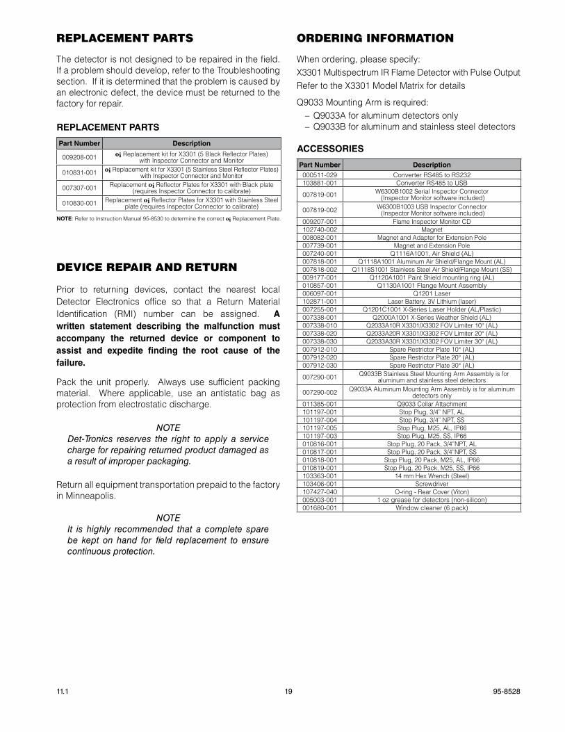
REPlaCEmENT PaRTS
The detector is not designed to be repaired in the field. If a problem should develop, refer to the Troubleshooting section. If it is determined that the problem is caused by an electronic defect, the device must be returned to the factory for repair.
REpLaCEMENT paRTS
part Number Description
009208-001 oi Replacement kit for X3301 (5 Black Reflector Plates) with Inspector Connector and Monitor
010831-001 oi Replacement kit for X3301 (5 Stainless Steel Reflector Plates) with Inspector Connector and Monitor
007307-001 Replacement oi Reflector Plates for X3301 with Black plate (requires Inspector Connector to calibrate)
010830-001 Replacement oi Reflector Plates for X3301 with Stainless Steel plate (requires Inspector Connector to calibrate)
NOTE: Refer to Instruction Manual 95-8530 to determine the correct oi Replacement Plate.
DEVICE REPaIR aND RETURN
Prior to returning devices, contact the nearest local Detector Electronics office so that a Return Material Identification (RMI) number can be assigned. a written statement describing the malfunction must accompany the returned device or component to assist and expedite finding the root cause of the failure.
Pack the unit properly. Always use sufficient packing material. Where applicable, use an antistatic bag as protection from electrostatic discharge.
NOTEDet-Tronics reserves the right to apply a service charge for repairing returned product damaged as a result of improper packaging.
Return all equipment transportation prepaid to the factory in Minneapolis.
NOTEIt is highly recommended that a complete spare be kept on hand for field replacement to ensure continuous protection.
ORDERING INfORmaTION
When ordering, please specify:X3301 Multispectrum IR Flame Detector with Pulse OutputRefer to the X3301 Model Matrix for details
Q9033 Mounting Arm is required: – Q9033A for aluminum detectors only – Q9033B for aluminum and stainless steel detectors
aCCESSORIES
part Number Description000511-029 Converter RS485 to RS232103881-001 Converter RS485 to USB
007819-001 W6300B1002 Serial Inspector Connector (Inspector Monitor software included)
007819-002 W6300B1003 USB Inspector Connector (Inspector Monitor software included)
009207-001 Flame Inspector Monitor CD102740-002 Magnet008082-001 Magnet and Adapter for Extension Pole007739-001 Magnet and Extension Pole007240-001 Q1116A1001, Air Shield (AL)007818-001 Q1118A1001 Aluminum Air Shield/Flange Mount (AL)007818-002 Q1118S1001 Stainless Steel Air Shield/Flange Mount (SS)009177-001 Q1120A1001 Paint Shield mounting ring (AL)010857-001 Q1130A1001 Flange Mount Assembly006097-001 Q1201 Laser102871-001 Laser Battery, 3V Lithium (laser)007255-001 Q1201C1001 X-Series Laser Holder (AL/Plastic)007338-001 Q2000A1001 X-Series Weather Shield (AL)007338-010 Q2033A10R X3301/X3302 FOV Limiter 10° (AL)007338-020 Q2033A20R X3301/X3302 FOV Limiter 20° (AL)007338-030 Q2033A30R X3301/X3302 FOV Limiter 30° (AL)007912-010 Spare Restrictor Plate 10° (AL)007912-020 Spare Restrictor Plate 20° (AL)007912-030 Spare Restrictor Plate 30° (AL)
007290-001 Q9033B Stainless Steel Mounting Arm Assembly is for aluminum and stainless steel detectors
007290-002 Q9033A Aluminum Mounting Arm Assembly is for aluminum detectors only
011385-001 Q9033 Collar Attachment101197-001 Stop Plug, 3/4” NPT, AL101197-004 Stop Plug, 3/4” NPT, SS101197-005 Stop Plug, M25, AL, IP66101197-003 Stop Plug, M25, SS, IP66010816-001 Stop Plug, 20 Pack, 3/4”NPT, AL010817-001 Stop Plug, 20 Pack, 3/4”NPT, SS010818-001 Stop Plug, 20 Pack, M25, AL, IP66010819-001 Stop Plug, 20 Pack, M25, SS, IP66103363-001 14 mm Hex Wrench (Steel)103406-001 Screwdriver107427-040 O-ring - Rear Cover (Viton)005003-001 1 oz grease for detectors (non-silicon)001680-001 Window cleaner (6 pack)
95-852811.1 20
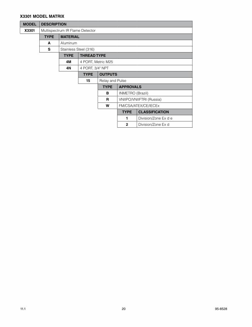
X3301 MODEL MaTRIX
MODEL DESCRIpTION
X3301 Multispectrum IR Flame Detector
TypE MaTERIaL
a Aluminum
S Stainless Steel (316)
TypE ThREaD TypE
4M 4 PORT, Metric M25
4N 4 PORT, 3/4" NPT
TypE OUTpUTS
15 Relay and Pulse
TypE appROvaLS
B INMETRO (Brazil)
R VNIIPO/VNIIFTRI (Russia)
W FM/CSA/ATEX/CE/IECEx
TypE CLaSSIFICaTION
1 Division/Zone Ex d e
2 Division/Zone Ex d

21 95-852811.1
aPPENDIX a
FM appROvaL aND pERFORMaNCE REpORT
THE FOLLOWING ITEMS, FUNCTIONS AND OPTIONS DESCRIBE THE FM APPROVAL:
• Explosion-proof for Class I, Div. 1, Groups B, C and D (T4A) Hazardous (Classified) Locations per FM 3615.
• Dust-ignition proof for Class II/III, Div. 1, Groups E, F and G (T4A) Hazardous (Classified) Locations per FM 3615.
• Nonincendive for Class I, Div. 2, Groups A, B, C and D (T3C) Hazardous (Classified) Locations per FM 3611.
• Nonincendive for Class II, Div. 2, Groups F and G (T3C) Hazardous (Classified) Locations per FM 3611.
• Enclosure rating NEMA/Type 4X per NEMA 250.
• Ambient Temperature Limits: –40°F to +167°F (–40°C to +75°C).
• Automatic Fire Alarm Signaling Performance verified per FM 3260 (2000).
Flameproof per ANSI/ISA 60079-0, -1, -7, -31 for Class I, Zone 1 - AEx d e IIC Gb; T6 (Tamb –40°C to +60°C); T5 (Tamb –40°C to +75°C) AEx d IIC Gb; T6 (Tamb –40°C to +60°C); T5 (Tamb –40°C to +75°C)
for Zone 21 - AEx tb T130°C Db Tamb –40°C to +75°C
Degree of protection provided by Enclosure IP66/67, Hazardous Locations for use in the U.S.
The following accessories are FM approved for use with the X3301 Flame Detector:
part Number Description102740-002 Magnet007739-001 Magnet and Extension Pole010857-001 Q1130A1001 Flange Mount Assembly007290-001 Q9033B Stainless Steel Mounting Arm Assembly is for aluminum and stainless steel detectors007290-002 Q9033A Aluminum Mounting Arm Assembly is for aluminum detectors only 011385-001 Q9033 Collar Attachment
The following performance criteria were verified:
aUTOMaTIC OpTICaL INTEgRITy TEST:
The detector generated an optical fault in the presence of contamination on any single or combination of lens surfaces resulting in a loss of approximately 50% of its detection range, verifying that the detector performs a calibrated Automatic oi test for each sensor. Upon removal of the contamination, the detector fault was cleared and the detector was verified to detect a fire.
MaNUaL OpTICaL INTEgRITy TEST:
The Manual / Magnetic oi performs the same calibrated test as the Automatic oi, and additionally actuates the alarm relay to verify output operation. If there is a 50% loss of its detection range, an alarm signal is not generated.
The oi test procedure, as described in the “Magnetic oi / Manual oi” section of this instruction manual, is the approved external optical test method for this detector to verify end-to-end detector function. This test replaces the function and need of a traditional external test lamp.
95-852811.1 22
FM approval and performance Report – Continued
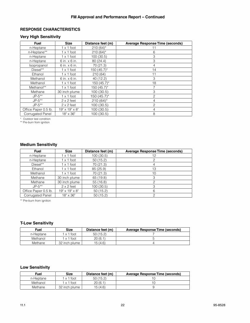
RESpONSE ChaRaCTERISTICS
very high Sensitivity
Fuel Size Distance feet (m) average Response Time (seconds)n-Heptane 1 x 1 foot 210 (64)* 11
n-Heptane** 1 x 1 foot 210 (64)* 6n-Heptane 1 x 1 foot 100 (30.5) 3n-Heptane 6 in. x 6 in. 80 (24.4) 3Isopropanol 6 in. x 6 in. 70 (21.3) 4
Diesel** 1 x 1 foot 150 (45.7)* 14Ethanol 1 x 1 foot 210 (64) 11
Methanol 6 in. x 6 in. 40 (12.2) 3Methanol 1 x 1 foot 150 (45.7)* 18
Methanol** 1 x 1 foot 150 (45.7)* 7Methane 30 inch plume 100 (30.5) 3
JP-5** 1 x 1 foot 150 (45.7)* 2JP-5** 2 x 2 feet 210 (64)* 4JP-5** 2 x 2 feet 100 (30.5) 2
Office Paper 0.5 lb. 19" x 19" x 8" 100 (30.5) 4Corrugated Panel 18" x 36" 100 (30.5) 8
* Outdoor test condition** Pre-burn from ignition
Medium Sensitivity
Fuel Size Distance feet (m) average Response Time (seconds)n-Heptane 1 x 1 foot 100 (30.5) 12n-Heptane 1 x 1 foot 50 (15.2) 2
Diesel** 1 x 1 foot 70 (21.3) 4Ethanol 1 x 1 foot 85 (25.9) 13
Methanol 1 x 1 foot 70 (21.3) 10Methane 30 inch plume 65 (19.8) 3Methane 30 inch plume 55 (16.8) 2
JP-5** 2 x 2 feet 100 (30.5) 3Office Paper 0.5 lb. 19" x 19" x 8" 50 (15.2) 6Corrugated Panel 18" x 36" 50 (15.2) 2
** Pre-burn from ignition
Low Sensitivity
Fuel Size Distance feet (m) average Response Time (seconds)n-Heptane 1 x 1 foot 50 (15.2) 10Methanol 1 x 1 foot 20 (6.1) 10Methane 32 inch plume 15 (4.6) 9
T-Low Sensitivity
Fuel Size Distance feet (m) average Response Time (seconds)n-Heptane 1 x 1 foot 50 (15.2) 7Methanol 1 x 1 foot 20 (6.1) 5Methane 32 inch plume 15 (4.6) 4
23 95-852811.1
FM approval and performance Report – Continued
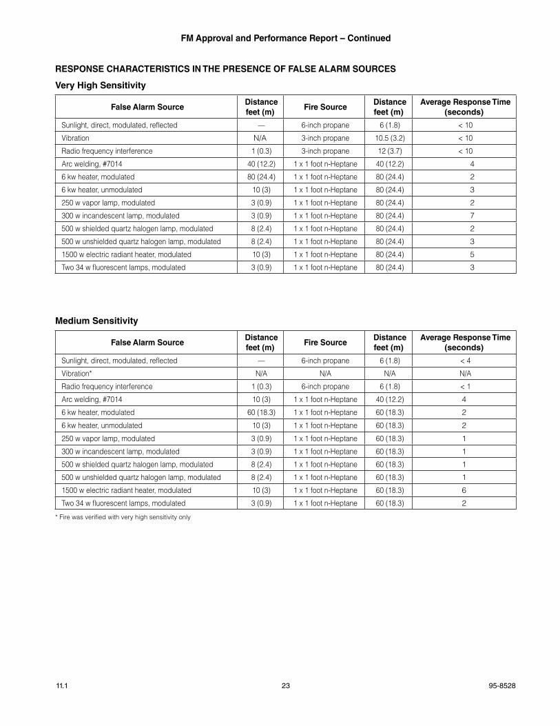
RESpONSE ChaRaCTERISTICS IN ThE pRESENCE OF FaLSE aLaRM SOURCES
very high Sensitivity
False alarm SourceDistancefeet (m)
Fire SourceDistancefeet (m)
average Response Time(seconds)
Sunlight, direct, modulated, reflected — 6-inch propane 6 (1.8) < 10
Vibration N/A 3-inch propane 10.5 (3.2) < 10
Radio frequency interference 1 (0.3) 3-inch propane 12 (3.7) < 10
Arc welding, #7014 40 (12.2) 1 x 1 foot n-Heptane 40 (12.2) 4
6 kw heater, modulated 80 (24.4) 1 x 1 foot n-Heptane 80 (24.4) 2
6 kw heater, unmodulated 10 (3) 1 x 1 foot n-Heptane 80 (24.4) 3
250 w vapor lamp, modulated 3 (0.9) 1 x 1 foot n-Heptane 80 (24.4) 2
300 w incandescent lamp, modulated 3 (0.9) 1 x 1 foot n-Heptane 80 (24.4) 7
500 w shielded quartz halogen lamp, modulated 8 (2.4) 1 x 1 foot n-Heptane 80 (24.4) 2
500 w unshielded quartz halogen lamp, modulated 8 (2.4) 1 x 1 foot n-Heptane 80 (24.4) 3
1500 w electric radiant heater, modulated 10 (3) 1 x 1 foot n-Heptane 80 (24.4) 5
Two 34 w fluorescent lamps, modulated 3 (0.9) 1 x 1 foot n-Heptane 80 (24.4) 3
Medium Sensitivity
False alarm SourceDistancefeet (m)
Fire SourceDistancefeet (m)
average Response Time(seconds)
Sunlight, direct, modulated, reflected — 6-inch propane 6 (1.8) < 4
Vibration* N/A N/A N/A N/A
Radio frequency interference 1 (0.3) 6-inch propane 6 (1.8) < 1
Arc welding, #7014 10 (3) 1 x 1 foot n-Heptane 40 (12.2) 4
6 kw heater, modulated 60 (18.3) 1 x 1 foot n-Heptane 60 (18.3) 2
6 kw heater, unmodulated 10 (3) 1 x 1 foot n-Heptane 60 (18.3) 2
250 w vapor lamp, modulated 3 (0.9) 1 x 1 foot n-Heptane 60 (18.3) 1
300 w incandescent lamp, modulated 3 (0.9) 1 x 1 foot n-Heptane 60 (18.3) 1
500 w shielded quartz halogen lamp, modulated 8 (2.4) 1 x 1 foot n-Heptane 60 (18.3) 1
500 w unshielded quartz halogen lamp, modulated 8 (2.4) 1 x 1 foot n-Heptane 60 (18.3) 1
1500 w electric radiant heater, modulated 10 (3) 1 x 1 foot n-Heptane 60 (18.3) 6
Two 34 w fluorescent lamps, modulated 3 (0.9) 1 x 1 foot n-Heptane 60 (18.3) 2
* Fire was verified with very high sensitivity only
95-852811.1 24
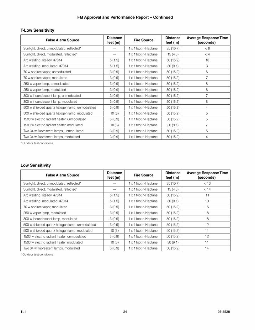
FM approval and performance Report – Continued
Low Sensitivity
False alarm SourceDistancefeet (m)
Fire SourceDistancefeet (m)
average Response Time(seconds)
Sunlight, direct, unmodulated, reflected* — 1 x 1 foot n-Heptane 35 (10.7) < 13
Sunlight, direct, modulated, reflected* — 1 x 1 foot n-Heptane 15 (4.6) < 14
Arc welding, steady, #7014 5 (1.5) 1 x 1 foot n-Heptane 50 (15.2) 11
Arc welding, modulated, #7014 5 (1.5) 1 x 1 foot n-Heptane 30 (9.1) 10
70 w sodium vapor, modulated 3 (0.9) 1 x 1 foot n-Heptane 50 (15.2) 16
250 w vapor lamp, modulated 3 (0.9) 1 x 1 foot n-Heptane 50 (15.2) 18
300 w incandescent lamp, modulated 3 (0.9) 1 x 1 foot n-Heptane 50 (15.2) 18
500 w shielded quartz halogen lamp, unmodulated 3 (0.9) 1 x 1 foot n-Heptane 50 (15.2) 12
500 w shielded quartz halogen lamp, modulated 10 (3) 1 x 1 foot n-Heptane 50 (15.2) 11
1500 w electric radiant heater, unmodulated 3 (0.9) 1 x 1 foot n-Heptane 50 (15.2) 12
1500 w electric radiant heater, modulated 10 (3) 1 x 1 foot n-Heptane 30 (9.1) 11
Two 34 w fluorescent lamps, modulated 3 (0.9) 1 x 1 foot n-Heptane 50 (15.2) 14
* Outdoor test conditions
T-Low Sensitivity
False alarm SourceDistancefeet (m)
Fire SourceDistancefeet (m)
average Response Time(seconds)
Sunlight, direct, unmodulated, reflected* — 1 x 1 foot n-Heptane 35 (10.7) < 6
Sunlight, direct, modulated, reflected* — 1 x 1 foot n-Heptane 15 (4.6) < 4
Arc welding, steady, #7014 5 (1.5) 1 x 1 foot n-Heptane 50 (15.2) 10
Arc welding, modulated, #7014 5 (1.5) 1 x 1 foot n-Heptane 30 (9.1) 3
70 w sodium vapor, unmodulated 3 (0.9) 1 x 1 foot n-Heptane 50 (15.2) 6
70 w sodium vapor, modulated 3 (0.9) 1 x 1 foot n-Heptane 50 (15.2) 7
250 w vapor lamp, unmodulated 3 (0.9) 1 x 1 foot n-Heptane 50 (15.2) 8
250 w vapor lamp, modulated 3 (0.9) 1 x 1 foot n-Heptane 50 (15.2) 6
300 w incandescent lamp, unmodulated 3 (0.9) 1 x 1 foot n-Heptane 50 (15.2) 7
300 w incandescent lamp, modulated 3 (0.9) 1 x 1 foot n-Heptane 50 (15.2) 8
500 w shielded quartz halogen lamp, unmodulated 3 (0.9) 1 x 1 foot n-Heptane 50 (15.2) 4
500 w shielded quartz halogen lamp, modulated 10 (3) 1 x 1 foot n-Heptane 50 (15.2) 5
1500 w electric radiant heater, unmodulated 3 (0.9) 1 x 1 foot n-Heptane 50 (15.2) 5
1500 w electric radiant heater, modulated 10 (3) 1 x 1 foot n-Heptane 30 (9.1) 7
Two 34 w fluorescent lamps, unmodulated 3 (0.9) 1 x 1 foot n-Heptane 50 (15.2) 5
Two 34 w fluorescent lamps, modulated 3 (0.9) 1 x 1 foot n-Heptane 50 (15.2) 4
* Outdoor test conditions
25 95-852811.1
FM approval and performance Report – Continued
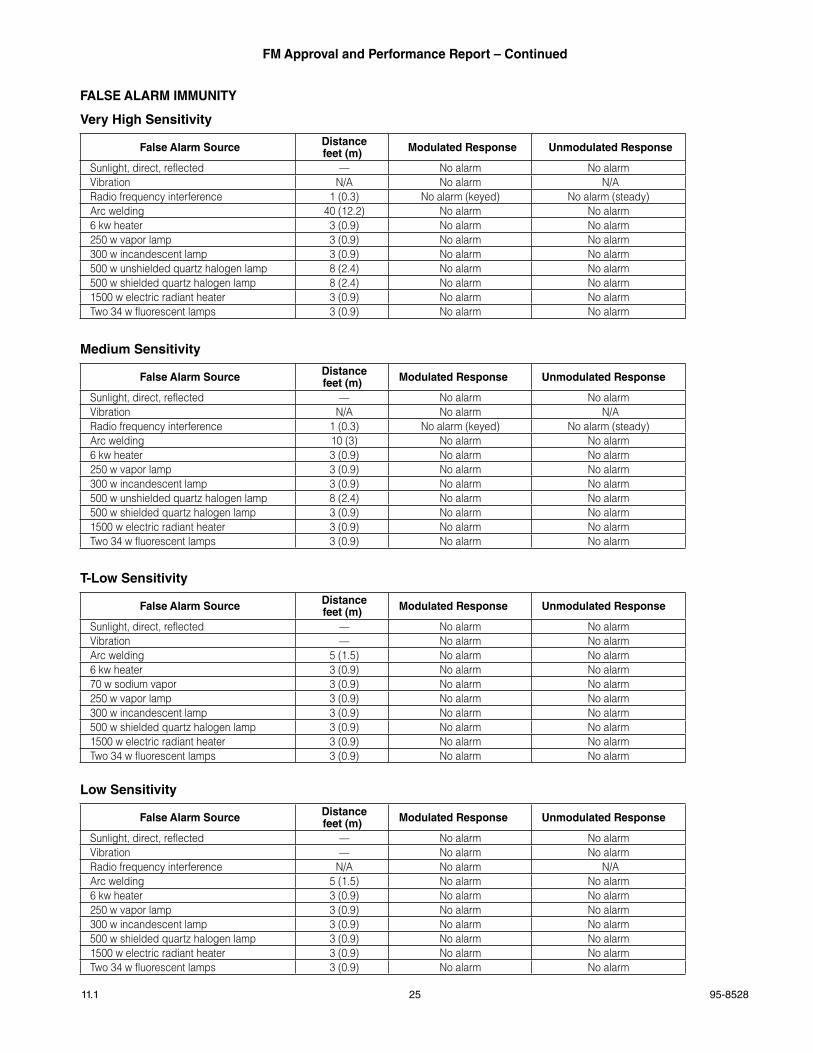
FaLSE aLaRM IMMUNITy
very high Sensitivity
False alarm Source Distancefeet (m) Modulated Response Unmodulated Response
Sunlight, direct, reflected — No alarm No alarmVibration N/A No alarm N/ARadio frequency interference 1 (0.3) No alarm (keyed) No alarm (steady)Arc welding 40 (12.2) No alarm No alarm6 kw heater 3 (0.9) No alarm No alarm250 w vapor lamp 3 (0.9) No alarm No alarm300 w incandescent lamp 3 (0.9) No alarm No alarm500 w unshielded quartz halogen lamp 8 (2.4) No alarm No alarm500 w shielded quartz halogen lamp 8 (2.4) No alarm No alarm1500 w electric radiant heater 3 (0.9) No alarm No alarmTwo 34 w fluorescent lamps 3 (0.9) No alarm No alarm
Medium Sensitivity
False alarm Source Distancefeet (m) Modulated Response Unmodulated Response
Sunlight, direct, reflected — No alarm No alarmVibration N/A No alarm N/ARadio frequency interference 1 (0.3) No alarm (keyed) No alarm (steady)Arc welding 10 (3) No alarm No alarm6 kw heater 3 (0.9) No alarm No alarm250 w vapor lamp 3 (0.9) No alarm No alarm300 w incandescent lamp 3 (0.9) No alarm No alarm500 w unshielded quartz halogen lamp 8 (2.4) No alarm No alarm500 w shielded quartz halogen lamp 3 (0.9) No alarm No alarm1500 w electric radiant heater 3 (0.9) No alarm No alarmTwo 34 w fluorescent lamps 3 (0.9) No alarm No alarm
T-Low Sensitivity
False alarm Source Distancefeet (m) Modulated Response Unmodulated Response
Sunlight, direct, reflected — No alarm No alarmVibration — No alarm No alarmArc welding 5 (1.5) No alarm No alarm6 kw heater 3 (0.9) No alarm No alarm70 w sodium vapor 3 (0.9) No alarm No alarm250 w vapor lamp 3 (0.9) No alarm No alarm300 w incandescent lamp 3 (0.9) No alarm No alarm500 w shielded quartz halogen lamp 3 (0.9) No alarm No alarm1500 w electric radiant heater 3 (0.9) No alarm No alarmTwo 34 w fluorescent lamps 3 (0.9) No alarm No alarm
Low Sensitivity
False alarm Source Distancefeet (m) Modulated Response Unmodulated Response
Sunlight, direct, reflected — No alarm No alarmVibration — No alarm No alarmRadio frequency interference N/A No alarm N/AArc welding 5 (1.5) No alarm No alarm6 kw heater 3 (0.9) No alarm No alarm250 w vapor lamp 3 (0.9) No alarm No alarm300 w incandescent lamp 3 (0.9) No alarm No alarm500 w shielded quartz halogen lamp 3 (0.9) No alarm No alarm1500 w electric radiant heater 3 (0.9) No alarm No alarmTwo 34 w fluorescent lamps 3 (0.9) No alarm No alarm
95-852811.1 26
FM approval and performance Report – Continued
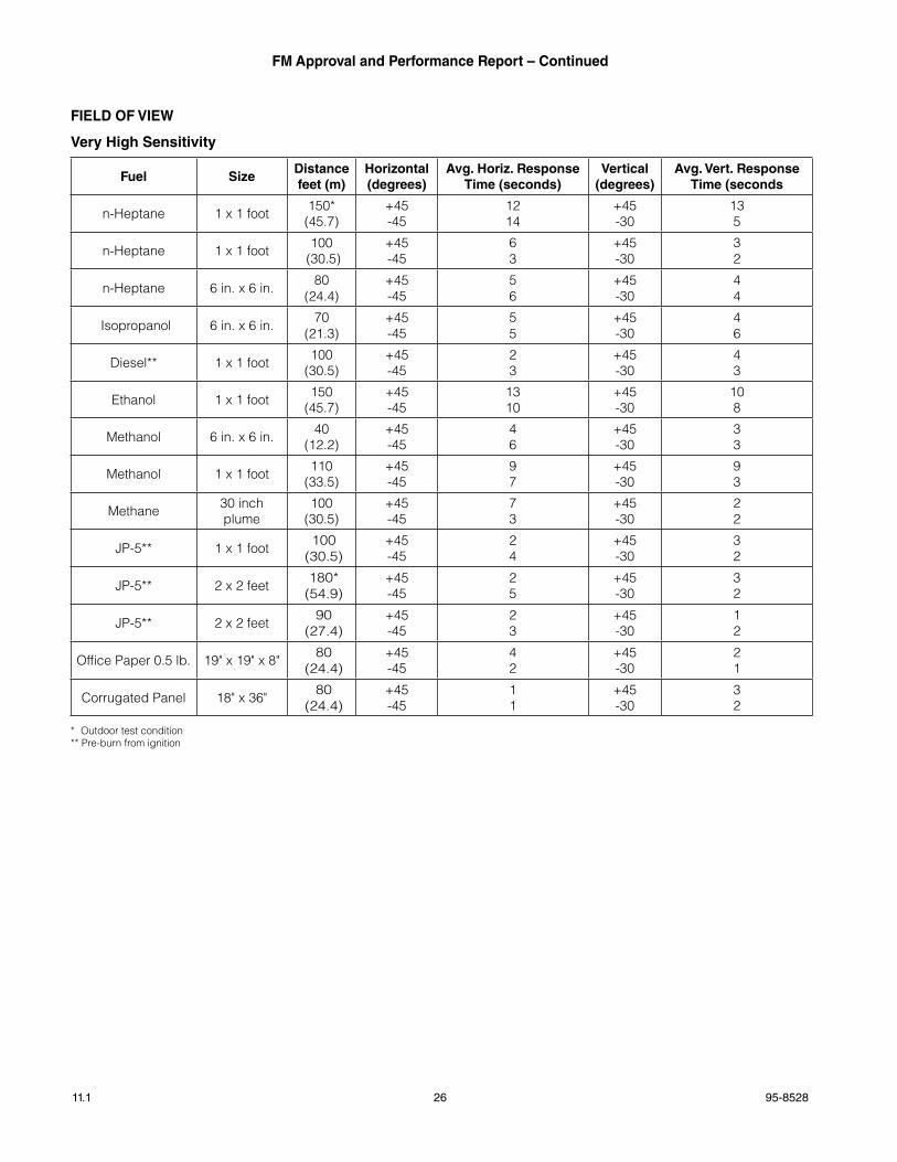
FIELD OF vIEW
very high Sensitivity
Fuel SizeDistance feet (m)
horizontal (degrees)
avg. horiz. Response Time (seconds)
vertical (degrees)
avg. vert. Response Time (seconds
n-Heptane 1 x 1 foot 150* (45.7)
+45-45
1214
+45-30
135
n-Heptane 1 x 1 foot 100 (30.5)
+45-45
63
+45-30
32
n-Heptane 6 in. x 6 in. 80(24.4)
+45-45
56
+45-30
44
Isopropanol 6 in. x 6 in. 70(21.3)
+45-45
55
+45-30
46
Diesel** 1 x 1 foot 100(30.5)
+45-45
23
+45-30
43
Ethanol 1 x 1 foot 150(45.7)
+45-45
1310
+45-30
108
Methanol 6 in. x 6 in. 40(12.2)
+45-45
46
+45-30
33
Methanol 1 x 1 foot 110(33.5)
+45-45
97
+45-30
93
Methane 30 inch plume
100(30.5)
+45-45
73
+45-30
22
JP-5** 1 x 1 foot 100 (30.5)
+45-45
24
+45-30
32
JP-5** 2 x 2 feet 180* (54.9)
+45-45
25
+45-30
32
JP-5** 2 x 2 feet 90 (27.4)
+45-45
23
+45-30
12
Office Paper 0.5 lb. 19" x 19" x 8" 80 (24.4)
+45-45
42
+45-30
21
Corrugated Panel 18" x 36" 80 (24.4)
+45-45
11
+45-30
32
* Outdoor test condition** Pre-burn from ignition
27 95-852811.1
FM approval and performance Report – Continued
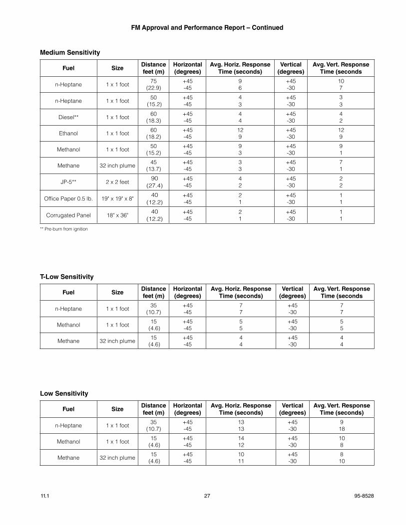
Medium Sensitivity
Fuel SizeDistance feet (m)
horizontal (degrees)
avg. horiz. Response Time (seconds)
vertical (degrees)
avg. vert. Response Time (seconds
n-Heptane 1 x 1 foot 75(22.9)
+45-45
96
+45-30
107
n-Heptane 1 x 1 foot 50 (15.2)
+45-45
43
+45-30
33
Diesel** 1 x 1 foot 60(18.3)
+45-45
44
+45-30
42
Ethanol 1 x 1 foot 60(18.2)
+45-45
129
+45-30
129
Methanol 1 x 1 foot 50(15.2)
+45-45
93
+45-30
91
Methane 32 inch plume 45(13.7)
+45-45
33
+45-30
71
JP-5** 2 x 2 feet90
(27.4)+45-45
42
+45-30
22
Office Paper 0.5 lb. 19" x 19" x 8"40
(12.2)+45-45
21
+45-30
11
Corrugated Panel 18" x 36"40
(12.2)+45-45
21
+45-30
11
** Pre-burn from ignition
T-Low Sensitivity
Fuel SizeDistance feet (m)
horizontal (degrees)
avg. horiz. Response Time (seconds)
vertical (degrees)
avg. vert. Response Time (seconds
n-Heptane 1 x 1 foot 35(10.7)
+45-45
77
+45-30
77
Methanol 1 x 1 foot 15 (4.6)
+45-45
55
+45-30
55
Methane 32 inch plume 15 (4.6)
+45-45
44
+45-30
44
Low Sensitivity
Fuel SizeDistance feet (m)
horizontal (degrees)
avg. horiz. Response Time (seconds)
vertical (degrees)
avg. vert. Response Time (seconds)
n-Heptane 1 x 1 foot 35(10.7)
+45-45
1313
+45-30
918
Methanol 1 x 1 foot 15 (4.6)
+45-45
1412
+45-30
108
Methane 32 inch plume 15 (4.6)
+45-45
1011
+45-30
810
95-852811.1 28
FM approval and performance Report – Continued
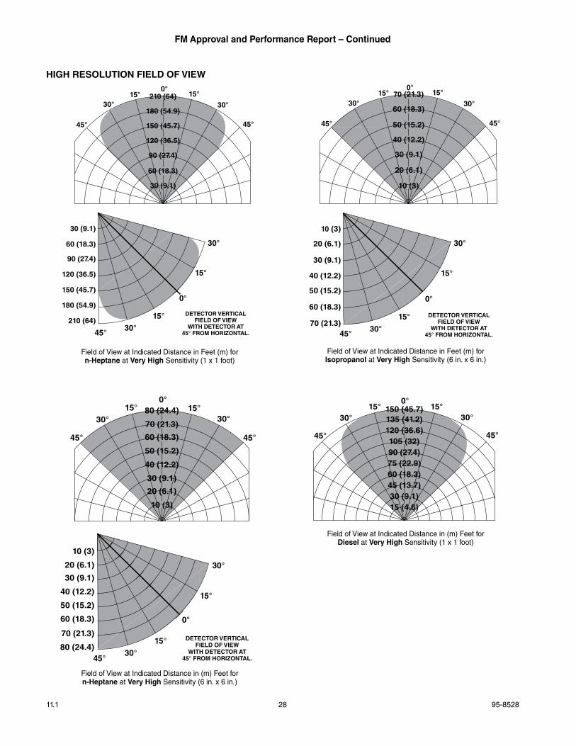
field of View at Indicated Distance in (m) feet for n-heptane at very high Sensitivity (6 in . x 6 in .)
field of View at Indicated Distance in feet (m) for Isopropanol at very high Sensitivity (6 in . x 6 in .)
hIgh RESOLUTION FIELD OF vIEW
field of View at Indicated Distance in (m) feet for Diesel at very high Sensitivity (1 x 1 foot)
field of View at Indicated Distance in feet (m) for n-heptane at very high Sensitivity (1 x 1 foot)
0°
15°
45°
15°
30°
30°
DETECTOR VERTICALFIELD OF VIEW
WITH DETECTOR AT45° FROM HORIZONTAL.
0°15°15°
30°
45°
30°
45°
210 (64)
180 (54.9)
150 (45.7)
120 (36.5)
90 (27.4)
60 (18.3)
30 (9.1)
30 (9.1)
60 (18.3)
90 (27.4)
120 (36.5)
150 (45.7)
180 (54.9)
210 (64)
0°
15°
45°
15°
30°
30°
DETECTOR VERTICALFIELD OF VIEW
WITH DETECTOR AT45° FROM HORIZONTAL.
0°15°15°
30°
45°
30°
45°
70 (21.3)
60 (18.3)
50 (15.2)
40 (12.2)
30 (9.1)
20 (6.1)
10 (3)
10 (3)
20 (6.1)
30 (9.1)
40 (12.2)
50 (15.2)
60 (18.3)
70 (21.3)
0°15°
30°
45°
15°30°
45°
0°
15°
45°
15°
30°
30°
DETECTOR VERTICALFIELD OF VIEW
WITH DETECTOR AT45° FROM HORIZONTAL.
80 (24.4)
70 (21.3)
60 (18.3)
50 (15.2)
40 (12.2)
30 (9.1)
20 (6.1)
10 (3)
10 (3)
20 (6.1)
30 (9.1)
40 (12.2)
50 (15.2)
60 (18.3)
70 (21.3)
80 (24.4)
0°15°
30°
45°
15°30°
45°
150 (45.7)135 (41.2)120 (36.6)105 (32)90 (27.4)75 (22.9)60 (18.3)45 (13.7)30 (9.1)15 (4.6)
29 95-852811.1
FM approval and performance Report – Continued
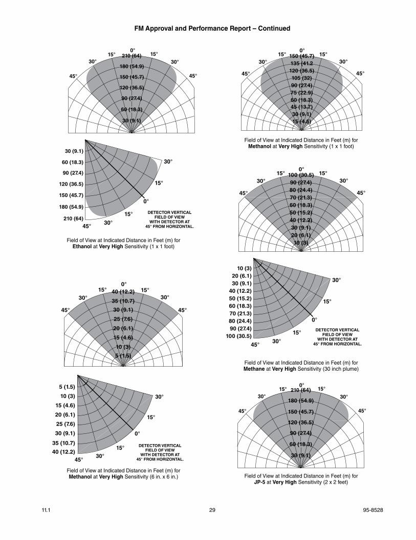
field of View at Indicated Distance in feet (m) for Methanol at very high Sensitivity (6 in . x 6 in .)
field of View at Indicated Distance in feet (m) for Methanol at very high Sensitivity (1 x 1 foot)
field of View at Indicated Distance in feet (m) for Jp-5 at very high Sensitivity (2 x 2 feet)
field of View at Indicated Distance in feet (m) for Methane at very high Sensitivity (30 inch plume)
field of View at Indicated Distance in feet (m) for Ethanol at very high Sensitivity (1 x 1 foot)
0°
15°
45°
15°
30°
30°
DETECTOR VERTICALFIELD OF VIEW
WITH DETECTOR AT45° FROM HORIZONTAL.
0°15°15°
30°
45°
30°
45°
210 (64)
180 (54.9)
150 (45.7)
120 (36.5)
90 (27.4)
60 (18.3)
30 (9.1)
30 (9.1)
60 (18.3)
90 (27.4)
120 (36.5)
150 (45.7)
180 (54.9)
210 (64)
0°15°
30°
45°
15°30°
45°
150 (45.7)135 (41.2120 (36.5)105 (32)90 (27.4)75 (22.9)60 (18.3)45 (13.7)30 (9.1)15 (4.6)
0°15°
30°
45°
15°30°
45°
0°
15°
45°
15°
30°
30°
DETECTOR VERTICALFIELD OF VIEW
WITH DETECTOR AT45° FROM HORIZONTAL.
100 (30.5)90 (27.4)80 (24.4)70 (21.3)60 (18.3)50 (15.2)40 (12.2)30 (9.1)20 (6.1)10 (3)
10 (3)20 (6.1)30 (9.1)
40 (12.2)50 (15.2)60 (18.3)70 (21.3)80 (24.4)90 (27.4)
100 (30.5)
0°15°
30°
45°
15°30°
45°
0°
15°
45°
15°
30°
30°
DETECTOR VERTICALFIELD OF VIEW
WITH DETECTOR AT45° FROM HORIZONTAL.
40 (12.2)
35 (10.7)
30 (9.1)
25 (7.6)
20 (6.1)
15 (4.6)
10 (3)
5 (1.5)
5 (1.5)
10 (3)
15 (4.6)
20 (6.1)
25 (7.6)
30 (9.1)
35 (10.7)
40 (12.2)
0°15°15°
30°
45°
30°
45°
210 (64)
180 (54.9)
150 (45.7)
120 (36.5)
90 (27.4)
60 (18.3)
30 (9.1)
95-852811.1 30
FM approval and performance Report – Continued
NOTEFM Approvals minimum requirements are response distance measurements at 0° (on axis) and the limits of the field of view. These high resolution field of view diagrams show the measured response distances at all the indicated angles in the horizontal plane.
field of View at Indicated Distance in feet (m) for n-heptane at Medium Sensitivity (1 x 1 foot)
field of View at Indicated Distance in feet (m) for Methane at Medium Sensitivity (30 inch plume)
field of View at Indicated Distance in feet (m) for Methanol at Medium Sensitivity (1 x 1 foot)
field of View at Indicated Distance in feet (m) for Jp-5 at Medium Sensitivity (2 x 2 foot)
field of View at Indicated Distance in feet (m) for Ethanol at Medium Sensitivity (1 x 1 foot)
field of View at Indicated Distance in feet (m) for Diesel at Medium Sensitivity (1 x 1 foot)
0°15°
30°
45°
15°30°
45°
100 (30.5)90 (27.4)80 (24.4)70 (21.3)60 (18.3)50 (15.2)40 (12.2)30 (9.1)20 (6.1)10 (3)
0°15°15°
30°
45°
30°
45°
70 (21.3)
60 (18.3)
50 (15.2)
40 (12.2)
30 (9.1)
20 (6.1)
10 (3)
0°15°
30°
45°
15°30°
45°
85 (25.9)80 (24.4)75 (22.9)65 (19.8)55 (16.8)45 (13.7)35 (10.7)25 (7.6)15 (4.6)5 (1.5)
0°15°15°
30°
45°
30°
45°
70 (21.3)
60 (18.3)
50 (15.2)
40 (12.2)
30 (9.1)
20 (6.1)
10 (3)
0°15°15°
30°
45°
30°
45°
65 ( 19.8)60 (18.3)
50 (15.2)
40 (12.2)
30 (9.1)
20 (6.1)
10 (3)
0°15°
30°
45°
15°30°
45°
100 (30.5)90 (27.4)80 (24.4)70 (21.3)60 (18.3)50 (15.2)40 (12.2)30 (9.1)20 (6.1)10 (3)
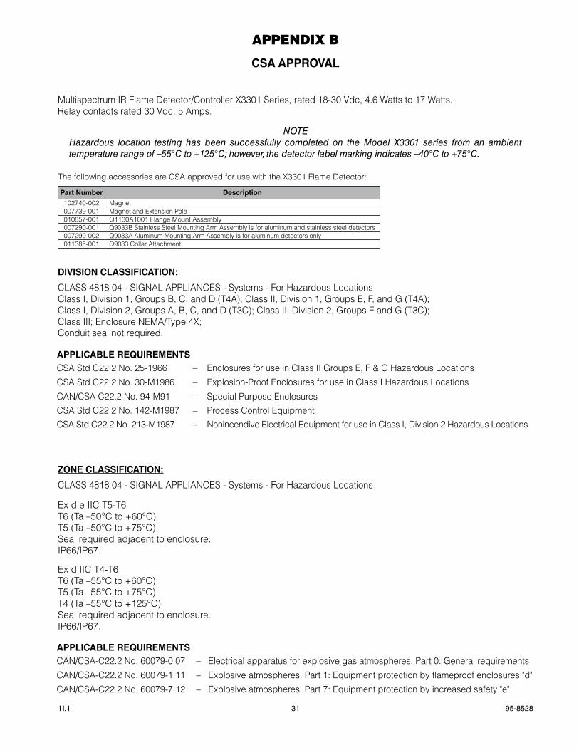
31 95-852811.1
aPPENDIX B
CSa appROvaL
Multispectrum IR Flame Detector/Controller X3301 Series, rated 18-30 Vdc, 4.6 Watts to 17 Watts.Relay contacts rated 30 Vdc, 5 Amps.
NOTEHazardous location testing has been successfully completed on the Model X3301 series from an ambient temperature range of –55°C to +125°C; however, the detector label marking indicates –40°C to +75°C.
The following accessories are CSA approved for use with the X3301 Flame Detector:
part Number Description102740-002 Magnet007739-001 Magnet and Extension Pole010857-001 Q1130A1001 Flange Mount Assembly007290-001 Q9033B Stainless Steel Mounting Arm Assembly is for aluminum and stainless steel detectors007290-002 Q9033A Aluminum Mounting Arm Assembly is for aluminum detectors only 011385-001 Q9033 Collar Attachment
DIvISION CLaSSIFICaTION:
CLASS 4818 04 - SIGNAL APPLIANCES - Systems - For Hazardous LocationsClass I, Division 1, Groups B, C, and D (T4A); Class II, Division 1, Groups E, F, and G (T4A);Class I, Division 2, Groups A, B, C, and D (T3C); Class II, Division 2, Groups F and G (T3C);Class III; Enclosure NEMA/Type 4X;Conduit seal not required.
ZONE CLaSSIFICaTION:
CLASS 4818 04 - SIGNAL APPLIANCES - Systems - For Hazardous Locations
Ex d e IIC T5-T6T6 (Ta –50°C to +60°C)T5 (Ta –50°C to +75°C)Seal required adjacent to enclosure.IP66/IP67.
Ex d IIC T4-T6T6 (Ta –55°C to +60°C)T5 (Ta –55°C to +75°C)T4 (Ta –55°C to +125°C)Seal required adjacent to enclosure.IP66/IP67.
appLICaBLE REQUIREMENTSCSA Std C22.2 No. 25-1966 – Enclosures for use in Class II Groups E, F & G Hazardous Locations
CSA Std C22.2 No. 30-M1986 – Explosion-Proof Enclosures for use in Class I Hazardous Locations
CAN/CSA C22.2 No. 94-M91 – Special Purpose EnclosuresCSA Std C22.2 No. 142-M1987 – Process Control EquipmentCSA Std C22.2 No. 213-M1987 – Nonincendive Electrical Equipment for use in Class I, Division 2 Hazardous Locations
appLICaBLE REQUIREMENTSCAN/CSA-C22.2 No. 60079-0:07 – Electrical apparatus for explosive gas atmospheres. Part 0: General requirements
CAN/CSA-C22.2 No. 60079-1:11 – Explosive atmospheres. Part 1: Equipment protection by flameproof enclosures "d"
CAN/CSA-C22.2 No. 60079-7:12 – Explosive atmospheres. Part 7: Equipment protection by increased safety "e"
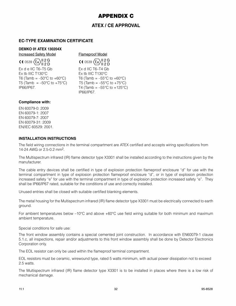
95-852811.1 32
aPPENDIX C
aTEX / CE appROvaL
EC-TypE EXaMINaTION CERTIFICaTE
DEMkO 01 aTEX 130204XIncreased Safety model flameproof model
0539
FMAPPROVED
®II 2 GII 2 D 0539
FM
APPROVED
®II 2 GII 2 D
Ex d e IIC T6–T5 Gb Ex d IIC T6–T4 GbEx tb IIIC T130°C Ex tb IIIC T130°CT6 (Tamb = –50°C to +60°C) T6 (Tamb = –55°C to +60°C) T5 (Tamb = –50°C to +75°C) T5 (Tamb = –55°C to +75°C) IP66/IP67. T4 (Tamb = –55°C to +125°C) IP66/IP67.
Compliance with:
EN 60079-0: 2009EN 60079-1: 2007EN 60079-7: 2007EN 60079-31: 2009EN/IEC 60529: 2001.
INSTaLLaTION INSTRUCTIONS
The field wiring connections in the terminal compartment are ATEX certified and accepts wiring specifications from 14-24 AWG or 2.5-0.2 mm2.
The Multispectrum infrared (IR) flame detector type X3301 shall be installed according to the instructions given by the manufacturer.
The cable entry devices shall be certified in type of explosion protection flameproof enclosure “d” for use with the terminal compartment in type of explosion protection flameproof enclosure “d”, or in type of explosion protection increased safety “e” for use with the terminal compartment in type of explosion protection increased safety “e”. They shall be IP66/IP67 rated, suitable for the conditions of use and correctly installed.
Unused entries shall be closed with suitable certified blanking elements.
The metal housing for the Multispectrum infrared (IR) flame detector type X3301 must be electrically connected to earth ground.
For ambient temperatures below –10°C and above +60°C use field wiring suitable for both minimum and maximum ambient temperature.
Special conditions for safe use:
The front window assembly contains a special cemented joint construction. In accordance with EN60079-1 clause 5.1.c, all inspections, repair and/or adjustments to this front window assembly shall be done by Detector Electronics Corporation only.
The EOL resistor can only be used within the flameproof terminal compartment.
EOL resistors must be ceramic, wirewound type, rated 5 watts minimum, with actual power dissipation not to exceed 2.5 watts.
The Multispectrum infrared (IR) flame detector type X3301 is to be installed in places where there is a low risk of mechanical damage.
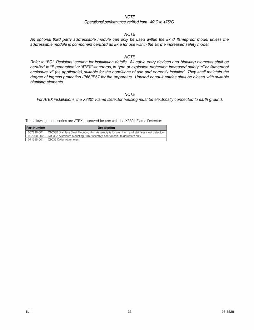
33 95-852811.1
NOTEOperational performance verified from –40°C to +75°C.
NOTEAn optional third party addressable module can only be used within the Ex d flameproof model unless the addressable module is component certified as Ex e for use within the Ex d e increased safety model.
NOTERefer to “EOL Resistors” section for installation details. All cable entry devices and blanking elements shall be certified to “E-generation” or “ATEX” standards, in type of explosion protection increased safety “e” or flameproof enclosure “d” (as applicable), suitable for the conditions of use and correctly installed. They shall maintain the degree of ingress protection IP66/IP67 for the apparatus. Unused conduit entries shall be closed with suitable blanking elements.
NOTEFor ATEX installations, the X3301 Flame Detector housing must be electrically connected to earth ground.
The following accessories are ATEX approved for use with the X3301 Flame Detector:
part Number Description007290-001 Q9033B Stainless Steel Mounting Arm Assembly is for aluminum and stainless steel detectors007290-002 Q9033A Aluminum Mounting Arm Assembly is for aluminum detectors only 011385-001 Q9033 Collar Attachment
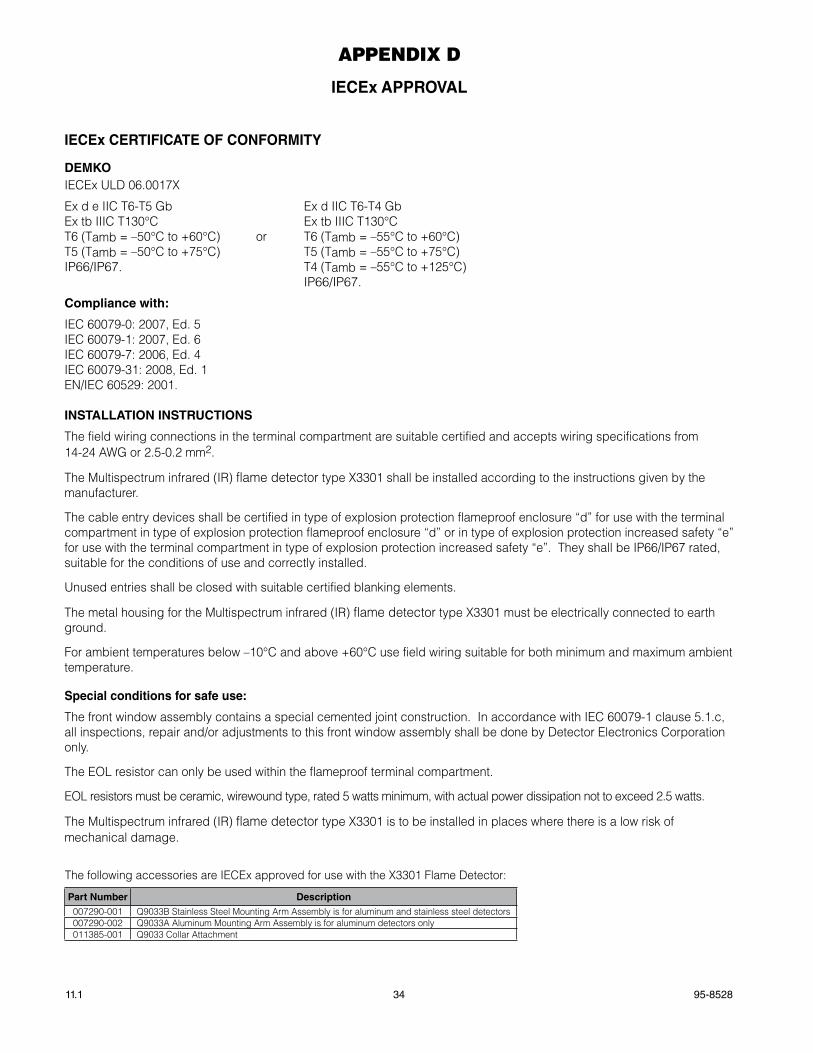
95-852811.1 34
aPPENDIX D
IECEx appROvaL
IECEx CERTIFICaTE OF CONFORMITy
DEMkOIECEx ULD 06.0017X
Ex d e IIC T6-T5 Gb Ex d IIC T6-T4 Gb Ex tb IIIC T130°C Ex tb IIIC T130°CT6 (Tamb = –50°C to +60°C) or T6 (Tamb = –55°C to +60°C)T5 (Tamb = –50°C to +75°C) T5 (Tamb = –55°C to +75°C) IP66/IP67. T4 (Tamb = –55°C to +125°C) IP66/IP67.
Compliance with:
IEC 60079-0: 2007, Ed. 5IEC 60079-1: 2007, Ed. 6IEC 60079-7: 2006, Ed. 4IEC 60079-31: 2008, Ed. 1EN/IEC 60529: 2001.
INSTaLLaTION INSTRUCTIONS
The field wiring connections in the terminal compartment are suitable certified and accepts wiring specifications from 14-24 AWG or 2.5-0.2 mm2.
The Multispectrum infrared (IR) flame detector type X3301 shall be installed according to the instructions given by the manufacturer.
The cable entry devices shall be certified in type of explosion protection flameproof enclosure “d” for use with the terminal compartment in type of explosion protection flameproof enclosure “d” or in type of explosion protection increased safety “e” for use with the terminal compartment in type of explosion protection increased safety “e”. They shall be IP66/IP67 rated, suitable for the conditions of use and correctly installed.
Unused entries shall be closed with suitable certified blanking elements.
The metal housing for the Multispectrum infrared (IR) flame detector type X3301 must be electrically connected to earth ground.
For ambient temperatures below –10°C and above +60°C use field wiring suitable for both minimum and maximum ambient temperature.
Special conditions for safe use:
The front window assembly contains a special cemented joint construction. In accordance with IEC 60079-1 clause 5.1.c, all inspections, repair and/or adjustments to this front window assembly shall be done by Detector Electronics Corporation only.
The EOL resistor can only be used within the flameproof terminal compartment.
EOL resistors must be ceramic, wirewound type, rated 5 watts minimum, with actual power dissipation not to exceed 2.5 watts.
The Multispectrum infrared (IR) flame detector type X3301 is to be installed in places where there is a low risk of mechanical damage.
The following accessories are IECEx approved for use with the X3301 Flame Detector:
part Number Description007290-001 Q9033B Stainless Steel Mounting Arm Assembly is for aluminum and stainless steel detectors007290-002 Q9033A Aluminum Mounting Arm Assembly is for aluminum detectors only 011385-001 Q9033 Collar Attachment
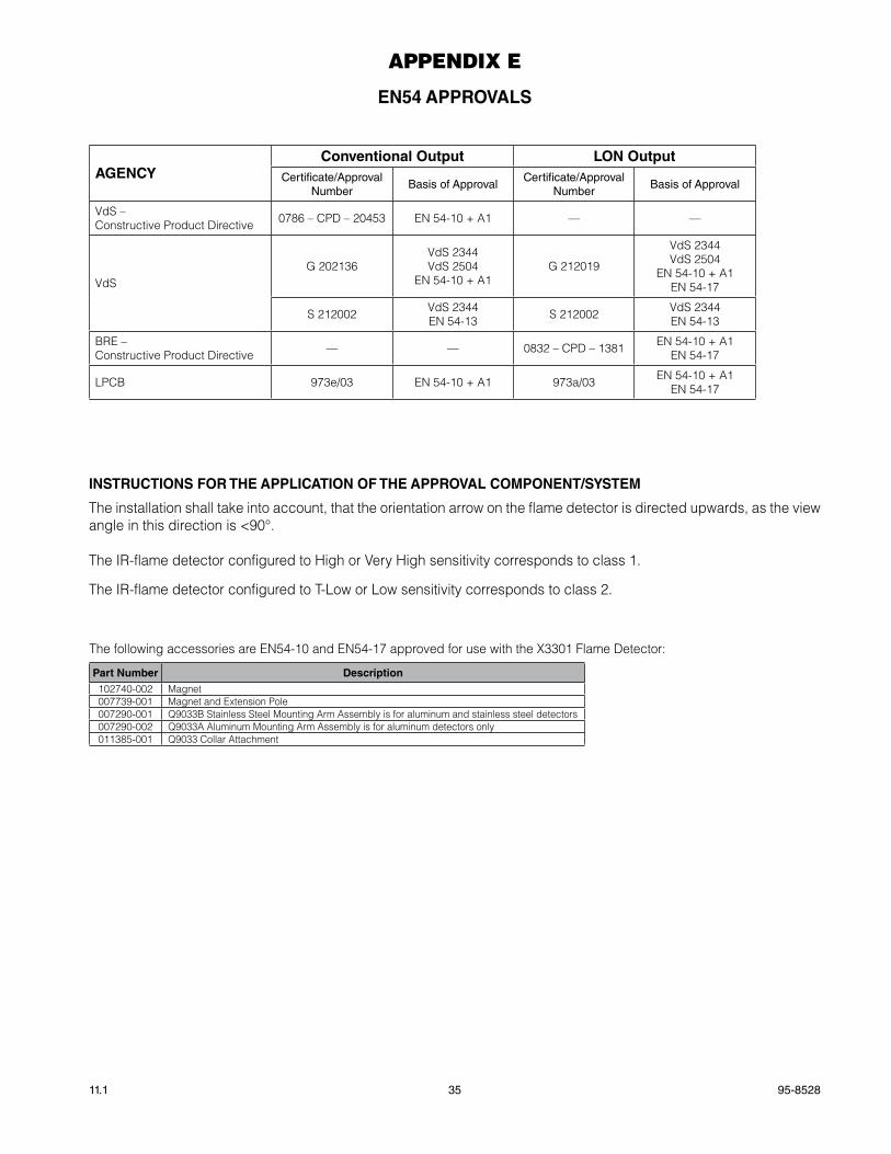
35 95-852811.1
aPPENDIX E
EN54 appROvaLS
agENCyConventional Output LON Output
Certificate/approval Number
Basis of approvalCertificate/approval
NumberBasis of approval
VdS – Constructive Product Directive 0786 – CPD – 20453 EN 54-10 + A1 — —
VdSG 202136
VdS 2344VdS 2504
EN 54-10 + A1G 212019
VdS 2344VdS 2504
EN 54-10 + A1EN 54-17
S 212002 VdS 2344EN 54-13 S 212002 VdS 2344
EN 54-13
BRE – Constructive Product Directive — — 0832 – CPD – 1381 EN 54-10 + A1
EN 54-17
LPCB 973e/03 EN 54-10 + A1 973a/03 EN 54-10 + A1EN 54-17
INSTRUCTIONS FOR ThE appLICaTION OF ThE appROvaL COMpONENT/SySTEM
The installation shall take into account, that the orientation arrow on the flame detector is directed upwards, as the view angle in this direction is <90°.
The IR-flame detector configured to High or Very High sensitivity corresponds to class 1.
The IR-flame detector configured to T-Low or Low sensitivity corresponds to class 2.
The following accessories are EN54-10 and EN54-17 approved for use with the X3301 Flame Detector:
part Number Description102740-002 Magnet007739-001 Magnet and Extension Pole007290-001 Q9033B Stainless Steel Mounting Arm Assembly is for aluminum and stainless steel detectors007290-002 Q9033A Aluminum Mounting Arm Assembly is for aluminum detectors only 011385-001 Q9033 Collar Attachment
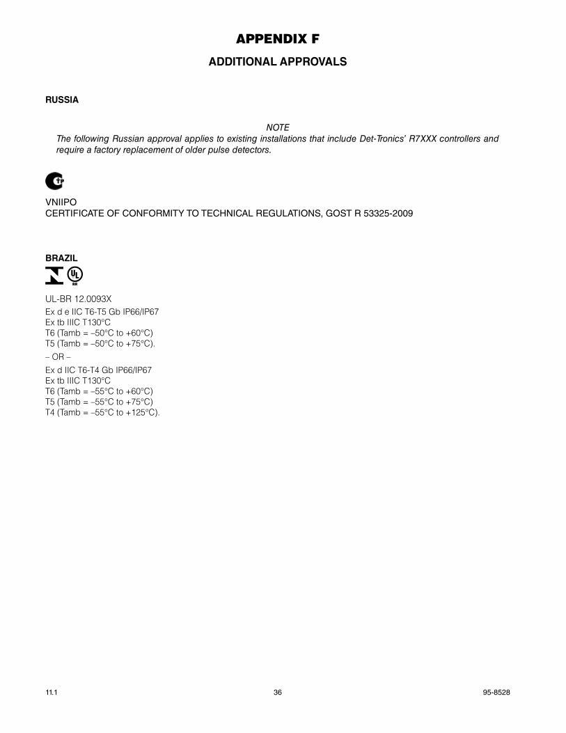
95-852811.1 36
aPPENDIX f
aDDITIONaL appROvaLS
RUSSIa
NOTEThe following Russian approval applies to existing installations that include Det-Tronics’ R7XXX controllers and require a factory replacement of older pulse detectors.
VNIIPOCERTIfICaTE Of CONfORmITy TO TECHNICaL REGULaTIONS, GOST R 53325-2009
BRaZIL
UL-BR 12.0093XEx d e IIC T6-T5 Gb IP66/IP67Ex tb IIIC T130°CT6 (Tamb = –50°C to +60°C)T5 (Tamb = –50°C to +75°C).– OR –Ex d IIC T6-T4 Gb IP66/IP67Ex tb IIIC T130°CT6 (Tamb = –55°C to +60°C)T5 (Tamb = –55°C to +75°C)T4 (Tamb = –55°C to +125°C).

Detector Electronics Corporation6901 West 110th Street
Minneapolis, MN 55438 USA
T: 952.941.5665 or 800.765.3473F: 952.829.8750
W: http://www.det-tronics.comE: [email protected]
X3301 Multispectrum IR Flame Detector
PointWatch Eclipse® IR Combustible Gas Detector
Eagle Quantum Premier® Safety System
FlexVu® Universal Displayw/ GT3000 Toxic Gas Detector
Det-Tronics and oi (Optical Integrity) are registered trademarks or trademarks of Detector Electronics Corporation in theUnited States, other countries, or both. Other company, product, or service names may be trademarks or service marks of others.
© Copyright Detector Electronics Corporation 2013. All rights reserved
95-8528