Embed Size (px)
Citation preview
Security Products
ISG 1000Hardware Installation and Configuration Guide
Juniper Networks, Inc.
1194 North Mathilda Avenue
Sunnyvale, CA 94089
USA
408-745-2000
www.juniper.net
Part Number: 093-1936-000, Revision B
2
Copyright Notice
Copyright © 2008 Juniper Networks, Inc. All rights reserved.
Juniper Networks, the Juniper Networks logo, NetScreen, and ScreenOS are registered trademarks of Juniper Networks, Inc. in the United States and other countries. All other trademarks, service marks, registered trademarks, or registered service marks in this document are the property of Juniper Networks or their respective owners. All specifications are subject to change without notice. Juniper Networks assumes no responsibility for any inaccuracies in this document or for any obligation to update information in this document. Juniper Networks reserves the right to change, modify, transfer, or otherwise revise this publication without notice.
FCC Statement
The following information is for FCC compliance of Class A devices: This equipment has been tested and found to comply with the limits for a Class A digital device, pursuant to part 15 of the FCC rules. These limits are designed to provide reasonable protection against harmful interference when the equipment is operated in a commercial environment. The equipment generates, uses, and can radiate radio-frequency energy and, if not installed and used in accordance with the instruction manual, may cause harmful interference to radio communications. Operation of this equipment in a residential area is likely to cause harmful interference, in which case users will be required to correct the interference at their own expense.
The following information is for FCC compliance of Class B devices: The equipment described in this manual generates and may radiate radio-frequency energy. If it is not installed in accordance with Juniper Networks’ installation instructions, it may cause interference with radio and television reception. This equipment has been tested and found to comply with the limits for a Class B digital device in accordance with the specifications in part 15 of the FCC rules. These specifications are designed to provide reasonable protection against such interference in a residential installation. However, there is no guarantee that interference will not occur in a particular installation.
If this equipment does cause harmful interference to radio or television reception, which can be determined by turning the equipment off and on, the user is encouraged to try to correct the interference by one or more of the following measures:
Reorient or relocate the receiving antenna.
Increase the separation between the equipment and receiver.
Consult the dealer or an experienced radio/TV technician for help.
Connect the equipment to an outlet on a circuit different from that to which the receiver is connected.
Caution: Changes or modifications to this product could void the user's warranty and authority to operate this device.
Disclaimer
THE SOFTWARE LICENSE AND LIMITED WARRANTY FOR THE ACCOMPANYING PRODUCT ARE SET FORTH IN THE INFORMATION PACKET THAT SHIPPED WITH THE PRODUCT AND ARE INCORPORATED HEREIN BY THIS REFERENCE. IF YOU ARE UNABLE TO LOCATE THE SOFTWARE LICENSE OR LIMITED WARRANTY, CONTACT YOUR JUNIPER NETWORKS REPRESENTATIVE FOR A COPY.
Table of Contents
About This Guide 5
Organization ....................................................................................................6Conventions.....................................................................................................6
Web User Interface Conventions ..............................................................6Command Line Interface Conventions ......................................................7
Requesting Technical Support ..........................................................................7Self-Help Online Tools and Resources........................................................7Opening a Case with JTAC .........................................................................8
Feedback .........................................................................................................8
Chapter 1 Hardware Overview 9
Port and Interface Module Slots .....................................................................10Front Panel ....................................................................................................11
Device Status LEDs..................................................................................11Port Descriptions .....................................................................................13
Ethernet Ports ...................................................................................13Compact Flash Slot ...........................................................................13Management Interfaces.....................................................................14
Interface Modules ....................................................................................1410/100 Mbps Interface Module..........................................................1410/100/1000 Mbps Interface Module.................................................15Mini-GBIC Interface Module...............................................................15
Fan Tray ..................................................................................................16Back Panel .....................................................................................................16
Chapter 2 Installing and Connecting a Device 17
Before You Begin ...........................................................................................18Equipment Installation ...................................................................................18Connecting the Power....................................................................................20
AC Power Supply Unit .............................................................................20DC Power Supply Unit .............................................................................20
Connecting Interface Cables to a Device ........................................................21Connecting a Device to a Network .................................................................22
Connecting an ISG 1000 Device to an Untrusted Network .......................22Connecting Ethernet Ports ................................................................23Connecting a Modem Port.................................................................24
Connecting a Device to an Internal Network or a Workstation ................24
Chapter 3 Configuring a Device 25
Default Device Settings ..................................................................................26Accessing a Device.........................................................................................27
Using a Console Connection ....................................................................27
Table of Contents 3
4
ISG 1000 Hardware Installation and Configuration Guide
Using Telnet ............................................................................................28Using Dialup ............................................................................................29Using the WebUI .....................................................................................29
Basic Device Configuration ............................................................................29Root Admin Name and Password ............................................................30Date and Time.........................................................................................31Administrative Access .............................................................................31Hostname and Domain Name .................................................................32Default Route...........................................................................................32Management Interface IP Address ...........................................................32Management Services..............................................................................33Trust Zone Interface IP Address...............................................................33Untrust Zone Interface IP Address ...........................................................34Policy Configuration ................................................................................34Device Alarm...........................................................................................35File Transferring ......................................................................................35
High Availability Configuration.......................................................................35Restarting the Device .....................................................................................38
Restarting the Device with the CLI Reset Command................................38Restarting the Device with the WebUI .....................................................38
Resetting a Device to Factory Defaults ...........................................................40Device Serial Number ..............................................................................40unset all...................................................................................................41
Chapter 4 Servicing the Device 43
Required Tools and Parts ...............................................................................44Interface Modules ..........................................................................................44
Remove Interface Module........................................................................44Insert Interface Module............................................................................45
Power Supply Units........................................................................................46DC Power Supply Replacement ...............................................................46AC Power Supply Replacement................................................................46
Fan Tray ........................................................................................................47Fan-Tray Filter ...............................................................................................48Cables and Transceivers.................................................................................49
Gigabit Ethernet Cables ...........................................................................49Mini-GBIC Transceiver .............................................................................50
Security Modules............................................................................................51
Appendix A Specifications 53
Physical..........................................................................................................53Electrical ........................................................................................................54Environmental ...............................................................................................54Certifications..................................................................................................54Connectors.....................................................................................................56
Index.......................................................................................................................... 59
Table of Contents
About This Guide
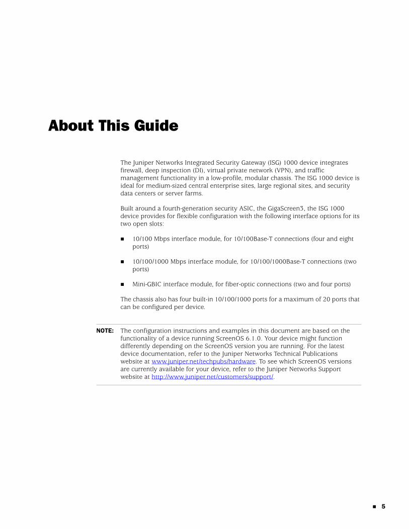
The Juniper Networks Integrated Security Gateway (ISG) 1000 device integrates firewall, deep inspection (DI), virtual private network (VPN), and traffic management functionality in a low-profile, modular chassis. The ISG 1000 device is ideal for medium-sized central enterprise sites, large regional sites, and security data centers or server farms.
Built around a fourth-generation security ASIC, the GigaScreen3, the ISG 1000 device provides for flexible configuration with the following interface options for its two open slots:
10/100 Mbps interface module, for 10/100Base-T connections (four and eight ports)
10/100/1000 Mbps interface module, for 10/100/1000Base-T connections (two ports)
Mini-GBIC interface module, for fiber-optic connections (two and four ports)
The chassis also has four built-in 10/100/1000 ports for a maximum of 20 ports that can be configured per device.
NOTE: The configuration instructions and examples in this document are based on the functionality of a device running ScreenOS 6.1.0. Your device might function differently depending on the ScreenOS version you are running. For the latest device documentation, refer to the Juniper Networks Technical Publications website at www.juniper.net/techpubs/hardware. To see which ScreenOS versions are currently available for your device, refer to the Juniper Networks Support website at http://www.juniper.net/customers/support/.
5
ISG 1000 Hardware Installation and Configuration Guide
6
Organization
This guide contains the following sections:
Chapter 1, “Hardware Overview,” describes the chassis and components of an ISG 1000 device.
Chapter 2, “Installing and Connecting a Device,” describes how to mount and connect cables and power to an ISG 1000 device.
Chapter 3, “Configuring a Device,” describes how to configure and manage an ISG 1000 device and how to perform some basic configuration tasks.
Chapter 4, “Servicing the Device,” describes service and maintenance procedures for an ISG 1000 device.
Appendix A, “Specifications,” provides general device specifications for an SSG 1000 device.
Conventions
This guide uses the conventions described in the following sections:
“Web User Interface Conventions” on page 6
“Command Line Interface Conventions” on page 7
Web User Interface Conventions The Web user interface (WebUI) contains a navigational path and configuration settings. To enter configuration settings, begin by clicking a menu item in the navigation tree on the left side of the screen. As you proceed, your navigation path appears at the top of the screen, with each page separated by angle brackets.
The following example shows the WebUI path and parameters for defining an address:
Policy > Policy Elements > Addresses > List > New: Enter the following, then click OK:
Address Name: addr_1IP Address/Domain Name:
IP/Netmask: (select), 10.2.2.5/32Zone: Untrust
To open online Help for configuration settings, click the question mark (?) in the upper left of the screen.
The navigation tree also provides a Help > Config Guide configuration page to help you configure security policies and Internet Protocol Security (IPSec). Select an option from the list and follow the instructions on the page. Click the ? character in the upper left for Online Help on the Config Guide.
Organization
Command Line Interface Conventions The following conventions are used to present the syntax of command line interface (CLI) commands in text and examples.
In text, commands are in boldface type and variables are in italic type.
In examples:
Variables are in italic type.
Anything inside square brackets [ ] is optional.
Anything inside braces { } is required.
If there is more than one choice, each choice is separated by a pipe ( | ). For example, the following command means “set the management options for the ethernet1, the ethernet2, or the ethernet3 interface”:
set interface { ethernet1 | ethernet2 | ethernet3 } manage
Requesting Technical Support
Technical product support is available through the Juniper Networks Technical Assistance Center (JTAC). If you are a customer with an active J-Care or JNASC support contract, or are covered under warranty, and need postsales technical support, you can access our tools and resources online or open a case with JTAC.
JTAC policies—For a complete understanding of our JTAC procedures and policies, review the JTAC User Guide located at http://www.juniper.net/customers/support/downloads/710059.pdf.
Product warranties—For product warranty information, visit http://www.juniper.net/support/warranty/.
JTAC hours of operation—The JTAC centers have resources available 24 hours a day, 7 days a week, 365 days a year.
Self-Help Online Tools and ResourcesFor quick and easy problem resolution, Juniper Networks has designed an online self-service portal called the Customer Support Center (CSC) that provides you with the following features:
Find CSC offerings—http://www.juniper.net/customers/support/
Find product documentation—http://www.juniper.net/techpubs/
NOTE: When entering a keyword, you only have to type enough letters to identify the word uniquely. For example, typing set adm u ang j12fmt54 is enough to enter the command set admin user angel j12fmt54. Although you can use this shortcut when entering commands, all the commands documented here are presented in their entirety.
Requesting Technical Support 7

ISG 1000 Hardware Installation and Configuration Guide
8
Find solutions and answer questions using our Knowledge Base— http://kb.juniper.net/
Download the latest versions of software and review your release notes— http://www.juniper.net/customers/csc/software/
Search technical bulletins for relevant hardware and software notifications— http://www.juniper.net/alerts/
Join and participate in the Juniper Networks Community Forum—http://www.juniper.net/company/communities/
Open a case online in the CSC Case Manager—http://www.juniper.net/customers/cm/
To verify service entitlement by product serial number, use our Serial Number Entitlement (SNE) Tool—https://tools.juniper.net/SerialNumberEntitlementSearch/
Opening a Case with JTACYou can open a case with JTAC on the Web or by telephone.
Use the Case Manager tool in the CSC at http://www.juniper.net/customers/cm/.
Call 1-888-314-JTAC (1-888-314-5822—toll free in USA, Canada, and Mexico).
For international or direct-dial options in countries without toll-free numbers, visit us at http://www.juniper.net/customers/support/requesting-support/.
Feedback
If you find any errors or omissions in this document, contact Juniper Networks at [email protected].
Feedback
Chapter 1
Hardware Overview
This chapter provides detailed descriptions of the ISG 1000 chassis and modular components. It includes the following sections:
“Port and Interface Module Slots” on page 10
“Front Panel” on page 11
“Back Panel” on page 16
9
ISG 1000 Hardware Installation and Configuration Guide
10
Port and Interface Module Slots
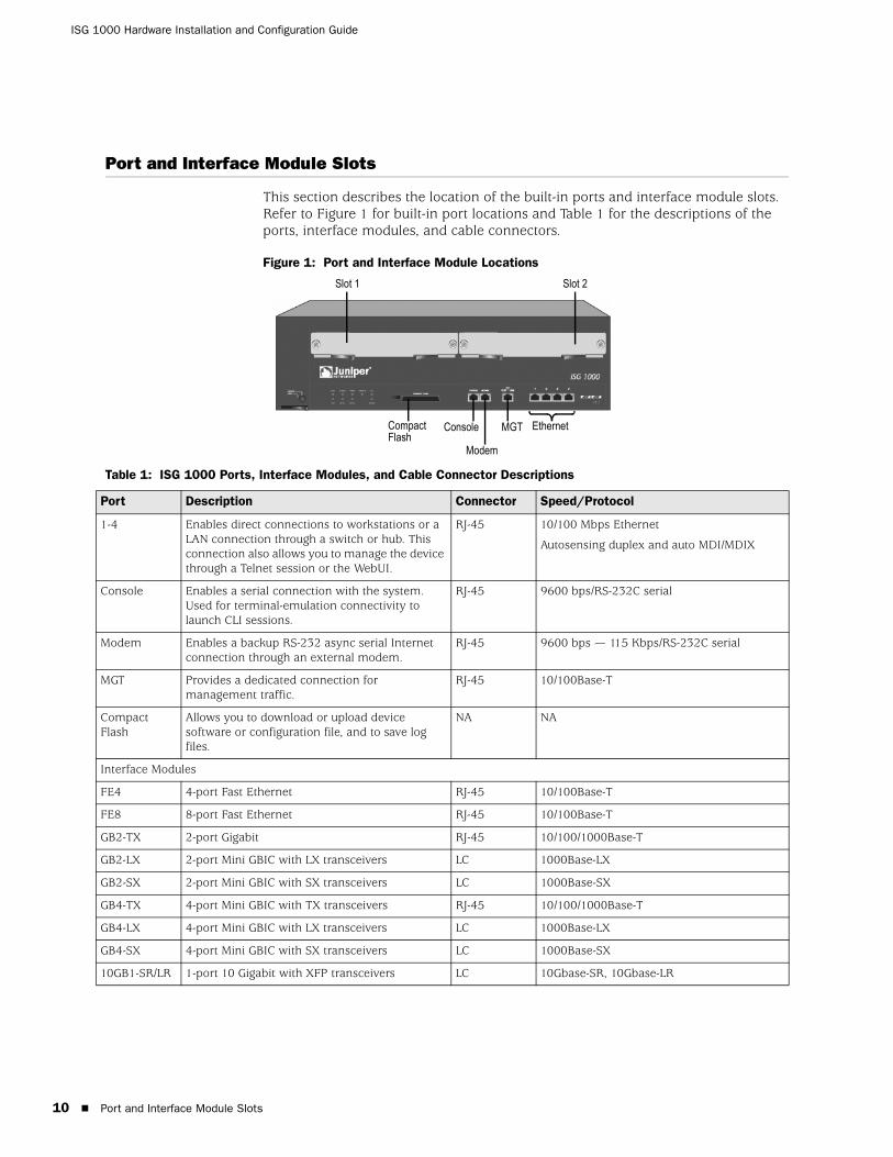
This section describes the location of the built-in ports and interface module slots. Refer to Figure 1 for built-in port locations and Table 1 for the descriptions of the ports, interface modules, and cable connectors.
Figure 1: Port and Interface Module Locations
Table 1: ISG 1000 Ports, Interface Modules, and Cable Connector Descriptions
Slot 1 Slot 2
EthernetMGTConsole
Modem
Compact Flash
Port Description Connector Speed/Protocol
1-4 Enables direct connections to workstations or a LAN connection through a switch or hub. This connection also allows you to manage the device through a Telnet session or the WebUI.
RJ-45 10/100 Mbps Ethernet
Autosensing duplex and auto MDI/MDIX
Console Enables a serial connection with the system. Used for terminal-emulation connectivity to launch CLI sessions.
RJ-45 9600 bps/RS-232C serial
Modem Enables a backup RS-232 async serial Internet connection through an external modem.
RJ-45 9600 bps — 115 Kbps/RS-232C serial
MGT Provides a dedicated connection for management traffic.
RJ-45 10/100Base-T
Compact Flash
Allows you to download or upload device software or configuration file, and to save log files.
NA NA
Interface Modules
FE4 4-port Fast Ethernet RJ-45 10/100Base-T
FE8 8-port Fast Ethernet RJ-45 10/100Base-T
GB2-TX 2-port Gigabit RJ-45 10/100/1000Base-T
GB2-LX 2-port Mini GBIC with LX transceivers LC 1000Base-LX
GB2-SX 2-port Mini GBIC with SX transceivers LC 1000Base-SX
GB4-TX 4-port Mini GBIC with TX transceivers RJ-45 10/100/1000Base-T
GB4-LX 4-port Mini GBIC with LX transceivers LC 1000Base-LX
GB4-SX 4-port Mini GBIC with SX transceivers LC 1000Base-SX
10GB1-SR/LR 1-port 10 Gigabit with XFP transceivers LC 10Gbase-SR, 10Gbase-LR
Port and Interface Module Slots
Front Panel
This section describes the follow elements on the front panel of an ISG 1000 device:
Device Status LEDs
Port Descriptions
Interface Modules
Fan Tray
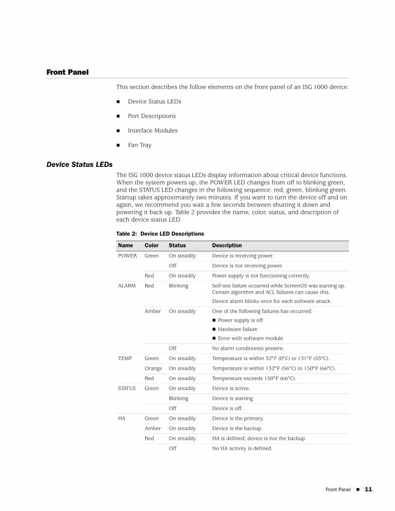
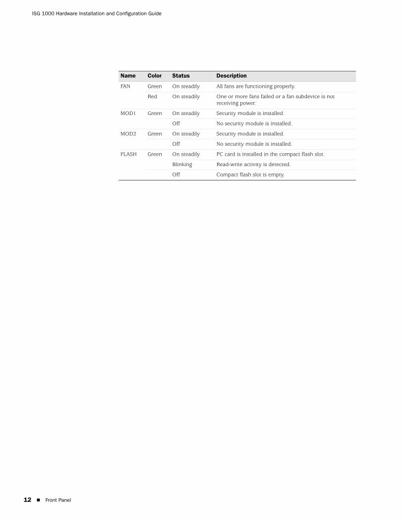
Device Status LEDsThe ISG 1000 device status LEDs display information about critical device functions. When the system powers up, the POWER LED changes from off to blinking green, and the STATUS LED changes in the following sequence: red, green, blinking green. Startup takes approximately two minutes. If you want to turn the device off and on again, we recommend you wait a few seconds between shutting it down and powering it back up. Table 2 provides the name, color, status, and description of each device status LED.
Table 2: Device LED Descriptions
Name Color Status Description
POWER Green On steadily Device is receiving power.
Off Device is not receiving power.
Red On steadily Power supply is not functioning correctly.
ALARM Red Blinking Self-test failure occurred while ScreenOS was starting up. Certain algorithm and ACL failures can cause this.
Device alarm blinks once for each software attack.
Amber On steadily One of the following failures has occurred:
Power supply is off
Hardware failure
Error with software module
Off No alarm condition(s) present.
TEMP Green On steadily Temperature is within 32°F (0°C) to 131°F (55°C).
Orange On steadily Temperature is within 132°F (56°C) to 150°F (66°C).
Red On steadily Temperature exceeds 150°F (66°C).
STATUS Green On steadily Device is active.
Blinking Device is starting.
Off Device is off.
HA Green On steadily Device is the primary.
Amber On steadily Device is the backup.
Red On steadily HA is defined; device is not the backup.
Off No HA activity is defined.
Front Panel 11
ISG 1000 Hardware Installation and Configuration Guide
12
FAN Green On steadily All fans are functioning properly.
Red On steadily One or more fans failed or a fan subdevice is not receiving power.
MOD1 Green On steadily Security module is installed.
Off No security module is installed.
MOD2 Green On steadily Security module is installed.
Off No security module is installed.
FLASH Green On steadily PC card is installed in the compact flash slot.
Blinking Read-write activity is detected.
Off Compact flash slot is empty.
Name Color Status Description
Front Panel
Port DescriptionsThis section explains the purpose and function of the following components:
Ethernet Ports
Compact Flash Slot
Management Interfaces
Ethernet PortsFour built-in 10/100 Ethernet ports provide LAN connections to hubs, switches, local servers, and workstations. You can also designate an Ethernet port for management traffic. The ports are labeled 1 through 4. For the default zone bindings for each Ethernet port, see “Interface-to-Zone Binding” on page 26.
When configuring one of the ports, refer to the interface name that corresponds to the location of the port. From left to right on the front panel, the interface names for the ports are ethernet1/1 through ethernet1/4.
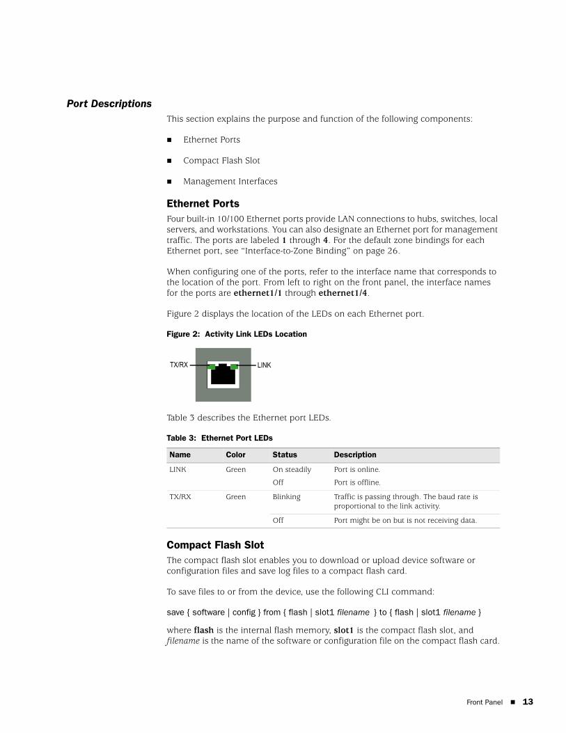
Figure 2 displays the location of the LEDs on each Ethernet port.
Figure 2: Activity Link LEDs Location
Table 3 describes the Ethernet port LEDs.
Table 3: Ethernet Port LEDs
Compact Flash SlotThe compact flash slot enables you to download or upload device software or configuration files and save log files to a compact flash card.
To save files to or from the device, use the following CLI command:
save { software | config } from { flash | slot1 filename } to { flash | slot1 filename }
where flash is the internal flash memory, slot1 is the compact flash slot, and filename is the name of the software or configuration file on the compact flash card.
Name Color Status Description
LINK Green On steadily
Off
Port is online.
Port is offline.
TX/RX Green Blinking Traffic is passing through. The baud rate is proportional to the link activity.
Off Port might be on but is not receiving data.
LINKTX/RX
Front Panel 13
ISG 1000 Hardware Installation and Configuration Guide
14
Management InterfacesThe ISG 1000 offers three management interfaces:
Console Port — This RJ-45 serial port wired as data circuit-terminating equipment (DCE) that can be used for local administration. Use a straight-through cable when using a terminal connection and a crossover cable when connecting to another DCE device. An RJ-45 to DB-9 adapter is supplied. See “Connectors” on page 56 for the RJ-45 connector pinouts.
Modem Port — This RJ-45 serial port, wired as data terminal equipment (DTE) that can be connected to a modem to allow remote administration. We do not recommend using this port for regular remote administration. Use a straight-through cable when connecting to a modem and a crossover cable when connecting to another DTE device. See “Connectors” on page 56 for the RJ-45 connector pinouts.
10/100 MGT Port — The management (MGT) port is a fixed 10/100Base-T interface that provides a dedicated connection for management traffic. It has a separate IP address and netmask (default is 192.168.1.1/24) and can be configured with the Web User Interface (WebUI) and the command line interface (CLI). The MGT port is only to be used for management purposes and is not capable of routing traffic to other interfaces.
Interface ModulesThe front panel of the ISG 1000 device has two interface module slots, which can accommodate the following types of interface modules:
10/100 Mbps
10/100/1000 Mbps
Mini-GBIC
The modules are not hot-swappable. Your network administrator needs to determine the kinds of interfaces needed to deploy an ISG 1000 device.
10/100 Mbps Interface ModuleThe four-port (FE4) or eight-port (FE8) 10/100 Mbps interface module is appropriate for a 10/100Base-T LAN. Connect the ports using a crossover cable with RJ-45 connectors.
NOTE: You can use one 10/100/1000 and one GBIC card in the same ISG 1000 device.
Front Panel
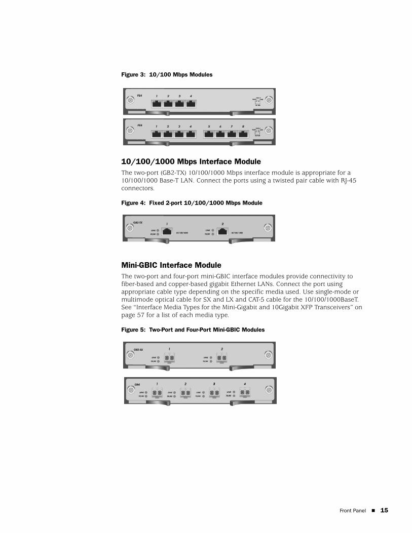
Figure 3: 10/100 Mbps Modules
10/100/1000 Mbps Interface ModuleThe two-port (GB2-TX) 10/100/1000 Mbps interface module is appropriate for a 10/100/1000 Base-T LAN. Connect the ports using a twisted pair cable with RJ-45 connectors.
Figure 4: Fixed 2-port 10/100/1000 Mbps Module
Mini-GBIC Interface ModuleThe two-port and four-port mini-GBIC interface modules provide connectivity to fiber-based and copper-based gigabit Ethernet LANs. Connect the port using appropriate cable type depending on the specific media used. Use single-mode or multimode optical cable for SX and LX and CAT-5 cable for the 10/100/1000BaseT. See “Interface Media Types for the Mini-Gigabit and 10Gigabit XFP Transceivers” on page 57 for a list of each media type.
Figure 5: Two-Port and Four-Port Mini-GBIC Modules
Front Panel 15
ISG 1000 Hardware Installation and Configuration Guide
16
Fan TrayThe ISG 1000 device has a single hot-swappable three-fan tray, which you can access on the left front side of the chassis.
Back Panel
The back panel of the ISG 1000 device contains a single factory-installed modular power supply unit (PSU). The PSU is available for AC or DC use and weighs 1.5 pounds (.45 kilograms). The PSU attaches with thumbscrews to allow field replacement. The POWER LED on the front panel of the ISG 1000 device glows either green or red. Green indicates correct function, and red indicates PSU failure.
The AC PSU faceplate contains a power switch and a male power outlet.
The DC PSU faceplate contains a power switch, hex nut, and three DC power terminal blocks that connect to power cables.
WARNING: If a fan stops operating as a result of failure or removal, the device continues to run. Do not leave the fan tray empty for more than two minutes; otherwise, heat failure or permanent damage could occur.
Back Panel
Chapter 2
Installing and Connecting a Device
This chapter describes how to install and connect an ISG 1000 device. It includes the following sections:
“Before You Begin” on page 18
“Equipment Installation” on page 18
“Connecting Interface Cables to a Device” on page 21
“Connecting a Device to a Network” on page 22
NOTE: For safety warnings and instructions, refer to the Juniper Networks Security Products Safety Guide. The guide warns you about situations that could cause bodily injury. When working on any equipment, be aware of the hazards involved with electrical circuitry, and follow standard practices for preventing accidents.
17
ISG 1000 Hardware Installation and Configuration Guide
18
Before You Begin
The location of the device, the layout of the equipment rack, and the security of your wiring room are crucial for proper device operation.
Observing the following precautions can prevent shutdowns, equipment failures, and injuries:
Before installation, always check that the power supply unit (PSU) is disconnected from any power source.
Ensure that the room in which you operate the device has adequate air circulation and that the room temperature does not exceed 122° F (50° C).
Allow three feet (one meter) of clear space to the front and back of the device.
Do not place the device in an equipment rack frame that blocks an intake or exhaust port. Ensure that enclosed racks have fans and louvered sides.
This device exceeds 36 pounds (16.3 kilograms). Take precautions when lifting and stabilizing the device.
Correct these hazardous conditions before any installation: moist or wet floors, leaks, ungrounded or frayed power cables, or missing safety grounds.
Equipment Installation
The ISG 1000 device fits into a standard 19-inch equipment rack and comes with two mounting brackets and six screws for front-mount or center-mount installation.
To mount the ISG 1000 device, you need a number-2 phillips screwdriver (not provided), the two mounting brackets, six screws (provided in the shipping box), and four screws that are compatible with the equipment rack (not provided).
When correctly installed, the ISG 1000 device sits level in the equipment rack.
To front-mount an ISG 1000 device:
1. Using three screws, attach one mounting bracket to the front of one side of the ISG 1000 device.
2. Using the remaining three screws, attach the other mounting bracket to the front of the other side of the device.
3. Slide the device into the rack.
4. Support the device while you attach the left and right brackets to the rack frame with the four screws (two on each side) that are compatible with the rack.
WARNING: To prevent abuse and intrusion by unauthorized personnel, install the ISG 1000 device in a secure environment.
Before You Begin
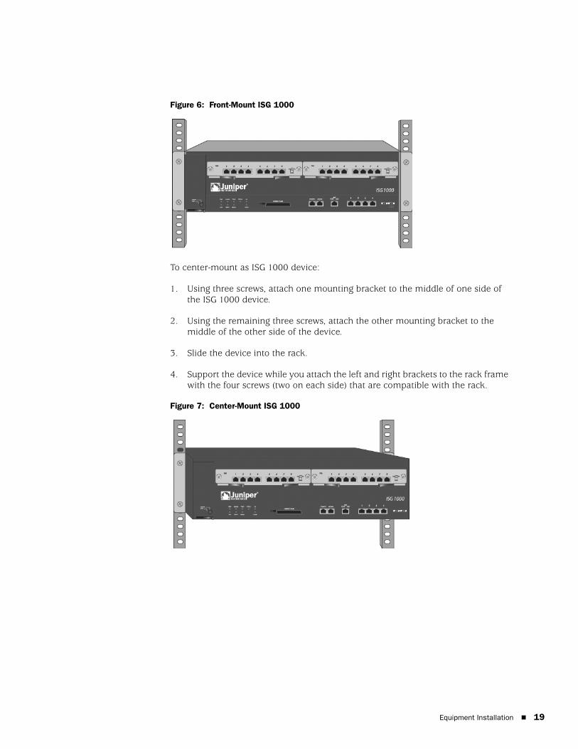
Figure 6: Front-Mount ISG 1000
To center-mount as ISG 1000 device:
1. Using three screws, attach one mounting bracket to the middle of one side of the ISG 1000 device.
2. Using the remaining three screws, attach the other mounting bracket to the middle of the other side of the device.
3. Slide the device into the rack.
4. Support the device while you attach the left and right brackets to the rack frame with the four screws (two on each side) that are compatible with the rack.
Figure 7: Center-Mount ISG 1000
Equipment Installation 19

ISG 1000 Hardware Installation and Configuration Guide
20
Connecting the Power
This section provides installation and connection procedures for the power supply units (PSUs) available for the ISG 1000.
AC Power Supply UnitTo install and connect an AC PSU to the ISG 1000:
1. Slide the PSU into one of the power compartments in the back of the device.
2. Fasten the PSU to the device by tightening the corner screws into the eyelets on the sides of the PSU.
3. Connect the female end of a standard power cord to the male connector on the back of the PSU.
4. Connect the power cord to a standard 100-240-volt power outlet.
5. Press the power switch to the ON position.
DC Power Supply UnitTo install and connect a DC PSU to the ISG 1000:
1. Slide the PSU into one of the power compartments in the back of the device.
2. Fasten the PSU to the device by tightening the corner screws into the eyelets on the PSU sides.
3. Remove the hex nut on the grounding screw.
4. Place the ground lug on the screw, then tighten the hex nut securely.
5. Connect the other end of the grounding lug wire to a grounding point at your site.
6. Loosen the retaining screws on each terminal block.
7. Insert the 0V DC (positive voltage) return wire into the center COM connector and the -48V DC power-feed wire into either the left or right connector.
8. Fasten the screws over the connectors.
9. Press the power switch to the ON position.
WARNING: You must shut off current to the DC feed wires before connecting the wires to the PSUs. Also, make sure that the ON/OFF switch is in the OFF position.
Connecting the Power
Connecting Interface Cables to a Device
To connect the interface cable to a device:
1. Have ready a length of the type of cable used by the interface.
2. Insert the cable connector into the cable-connector port on the interface faceplate.
3. Arrange the cable as follows to prevent it from dislodging or developing stress points:
a. Secure the cable so that it is not supporting its own weight as it hangs to the floor.
b. Place any excess cable out of the way in a neatly coiled loop.
c. Use fasteners to maintain the shape of the cable loops.
WARNING: Certain ports on the device are designed for use as intrabuilding (within-the-building) interfaces only (Type 2 or Type 4 ports as described in GR-1089-CORE, Isssue 4) and require isolation from the exposed outside plant (OSP) cabling. To comply with NEBS requirements and protect against lightning surges and commercial power disturbances, the intrabuilding ports must not be metallically connected to interfaces that connect to the OSP or its wiring. The intrabuilding ports on the device are suitable for connection to intrabuilding or unexposed wiring or cabling only. The addition of primary protectors is not sufficient protection for connecting these interfaces metallically to OSP wiring.
CAUTION: To comply with intrabuilding lightning and surge requirements, intrabuilding wiring must be shielded, and the shield for the wiring must be grounded at both ends.
Connecting Interface Cables to a Device 21
ISG 1000 Hardware Installation and Configuration Guide
22
Connecting a Device to a Network
An ISG 1000 device provides firewall and general security for networks when it is placed between internal networks and the untrusted network. This section describes the following:
Connecting an ISG 1000 Device to an Untrusted Network
Connecting a Device to an Internal Network or a Workstation
Connecting an ISG 1000 Device to an Untrusted NetworkYou can connect your ISG 1000 device to an untrusted network in one of the following ways:
Connecting Ethernet Ports
Connecting a Modem Port
The cabling instructions given below reproduce the configuration shown in Figure 8. However, this is not the only possible configuration. In addition, the instructions assume that you have configured all physical ports and interfaces through the Console port before cabling the device to a network.
The ports and interfaces are configured through the Console port as follows:
set interface ether1/1 zone dmzset interface ethernet2/1 zone untrustset interface ethernet3/8 zone trustset interface mgt managesave
Connecting a Device to a Network
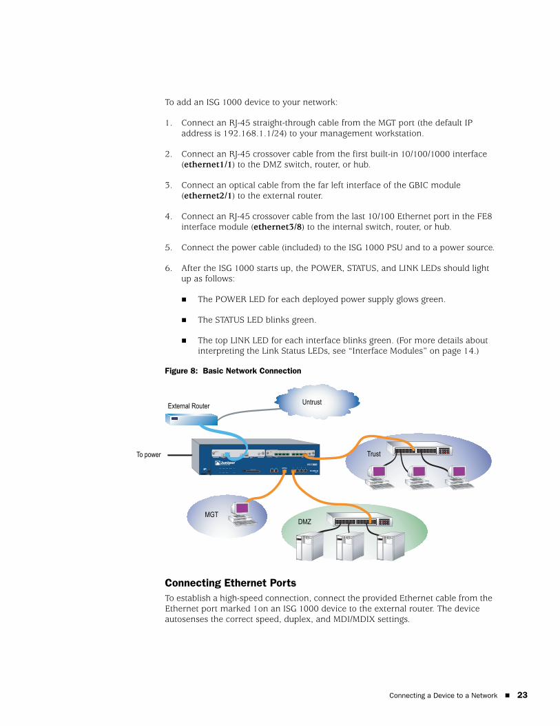
To add an ISG 1000 device to your network:
1. Connect an RJ-45 straight-through cable from the MGT port (the default IP address is 192.168.1.1/24) to your management workstation.
2. Connect an RJ-45 crossover cable from the first built-in 10/100/1000 interface (ethernet1/1) to the DMZ switch, router, or hub.
3. Connect an optical cable from the far left interface of the GBIC module (ethernet2/1) to the external router.
4. Connect an RJ-45 crossover cable from the last 10/100 Ethernet port in the FE8 interface module (ethernet3/8) to the internal switch, router, or hub.
5. Connect the power cable (included) to the ISG 1000 PSU and to a power source.
6. After the ISG 1000 starts up, the POWER, STATUS, and LINK LEDs should light up as follows:
The POWER LED for each deployed power supply glows green.
The STATUS LED blinks green.
The top LINK LED for each interface blinks green. (For more details about interpreting the Link Status LEDs, see “Interface Modules” on page 14.)
Figure 8: Basic Network Connection
Connecting Ethernet PortsTo establish a high-speed connection, connect the provided Ethernet cable from the Ethernet port marked 1on an ISG 1000 device to the external router. The device autosenses the correct speed, duplex, and MDI/MDIX settings.
Untrust External Router
To power Trust
DMZMGT
Connecting a Device to a Network 23
ISG 1000 Hardware Installation and Configuration Guide
24
Connecting a Modem PortYou can connect to the untrusted network with an RJ-45 straight-through serial cable and an external modem.
Connecting a Device to an Internal Network or a WorkstationAn ISG 1000 device contains four Ethernet ports. You can use one or more of these ports to connect to LANs through switches or hubs. You can also connect one or all of the ports directly to workstations, eliminating the need for a hub or switch. You can use either crossover or straight-through cables to connect the Ethernet ports to other devices. See “Default Device Settings” on page 26 for the default zone-to-interface bindings.
Connecting a Device to a Network
Chapter 3
Configuring a Device
This chapter describes how to connect and configure an ISG 1000 device in your network. It includes the following sections:
“Default Device Settings” on page 26
“Accessing a Device” on page 27
“Basic Device Configuration” on page 29
“High Availability Configuration” on page 35
“Restarting the Device” on page 38
“Resetting a Device to Factory Defaults” on page 40
NOTE: After you configure a device and verify connectivity through the remote network, you must register your product at http://www.juniper.net/customers/support/ so certain ScreenOS services, such as Deep Inspection Signature Service and Antivirus (purchased separately), can be activated on the device. After registering your product, use the WebUI to obtain the subscription for the service. For more information about registering your product and obtaining subscriptions for specific services, refer to the Concepts & Examples ScreenOS Reference Guide for the ScreenOS version running on the device.
25
ISG 1000 Installation and Configuration Guide
26
Default Device Settings
The ISG 1000 device supports a maximum of 20 ports, each of which can serve as a physical interface. You can also configure Ethernet ports to serve as virtual (logical) interfaces. The interfaces that can be configured on the ISG 1000 device are listed in the following tables.
Table 4: Interface-to-Zone Binding
Table 5: Logical Interface Naming
In Transparent mode, only the mgt and vlan1 interfaces require a new IP address and subnet mask. Other interfaces must keep the default IP address and subnet mask settings (0.0.0.0 and 0.0.0.0, respectively). To access the vlan1 interface, you must change the IP address and subnet mask of vlan1 to match the IP address of your current network.
In Route mode (default), you must configure at least two Ethernet interfaces with new IP addresses and subnet masks.
For information on configuring the operational modes, refer to the Concepts & Examples ScreenOS Reference Guide.
Port Label Interface Zone
Modem serial Untrust
MGT mgt (default IP address is 192.168.1.1/24) MGT
1 ethernet1/1 Null
2 ethernet1/2 Null
3 ethernet1/3 Null
4 ethernet1/4 Null
Interface Modules starting at ethernet2/1 and 3/1 from left to right Null
Interface Type Description
Ethernet interfaces ethernetn1/n2 specifies a physical Ethernet interface. Ports are numbered as follows: 1/1-n (four built-in 10/100/1000 Mbps ports), 2/1-n (top left module), and 3/1-n (top right module).
ethernetn1/n2.n3 specifies a sub-interface. Sub-interfaces are numbered as follows: 1/1-n (four built-in 10/100/1000 Mbps ports), 2/1-n (top left module), and 3/1-n (top right module) and a logical interface number ( .n3).
Layer-2 interfaces vlan1 specifies the interface used for VPNs while the device is in Transparent mode.
Tunnel interfaces tunnel.n specifies a tunnel interface. Use this interface for VPN traffic.
Functional interface mgt specifies an interface bound to the MGT zone. The default IP address of this interface is 192.168.1.1/24.
NOTE: For either operational mode, we strongly recommend that you change the default IP address and subnet mask for the mgt interface.
Default Device Settings
Accessing a Device
You can configure and manage a device in several ways:
Console: The Console port on the device allows you to access the device through a serial cable connected to your workstation or terminal. To configure the device, you enter ScreenOS command line interface (CLI) commands on your terminal or in a terminal-emulation program on your workstation.
WebUI: The ScreenOS Web user interface (WebUI) is a graphical interface available through a browser. To initially use the WebUI, the workstation on which you run the browser must be on the same subnetwork as the device. You can also access the WebUI through a secure server using Secure Sockets Layer (SSL) with secure HTTP (HTTPS).
Telnet/SSH: Telnet and SSH are applications that allow you to access devices through an IP network. To configure the device, you enter ScreenOS CLI commands in a Telnet session from your workstation. For more information, refer to the Concepts & Examples ScreenOS Reference Guide.
Network and Security Manager (NSM): NSM is a Juniper Networks enterprise-level management application that enables you to control and manage Juniper Networks firewall/IPSec VPN devices. For instructions on how to manage your device with NSM, refer to the Network and Security Manager documentation at http://www.juniper.net/techpubs/software/management/security-manager.
Using a Console Connection
To establish a console connection:
1. Plug the female end of the supplied DB-9 adapter into the serial port of your workstation. (Be sure that the DB-9 is inserted properly and secured.) Figure 9 shows the type of DB-9 connector that is required.
Figure 9: DB-9 Adapter
2. Plug the male end of the RJ-45 CAT5 serial cable into the Console port on the ISG 1000. (Be sure that the other end of the CAT5 cable is inserted properly and secured in the DB-9 adapter.)
NOTE: Use a straight-through RJ-45 CAT5 serial cable with a male RJ-45 connector to plug into the Console port on the device.
RJ-45 Jack
DB-9 Adapter
RJ-45 Cable
Accessing a Device 27
ISG 1000 Installation and Configuration Guide
28
3. Launch a serial terminal-emulation program on your workstation. The required settings to launch a console session are as follows:
Baud rate: 9600
Parity: None
Data bits: 8
Stop bit: 1
Flow Control: None
4. If you have not yet changed the default login for the login name and password, enter netscreen at both the login and password prompts. (Use lowercase letters only. The login and password fields are both case-sensitive)
For information on how to configure the device with the CLI commands, refer to the Concepts & Examples ScreenOS Reference Guide.
5. (Optional) By default, the console times out and terminates automatically after 10 minutes of idle time. To remove the timeout, enter set console timeout 0.
6. Once the command prompt is displayed, the device is ready to be configured, See “Basic Device Configuration” on page 29 to complete the initial device configuration.
Using TelnetTo establish a Telnet connection:
1. Connect your workstation to the MGT port (mgt interface) on the device.
2. Ensure that your workstation is configured for DHCP or is statically configured with an IP address in the 192.168.1.0/24 subnet.
3. Start a Telnet client application to the IP address for the mgt interface (the default IP address is 192.168.1.1). For example, enter telnet 192.168.1.1.
The Telnet application displays the login prompt.
4. If you have not yet changed the default login for the login name and password, enter netscreen at both the login and password prompts. (Use lowercase letters only. The login and password fields are both case-sensitive)
5. (Optional) By default, the console times out and terminates automatically after 10 minutes of idle time. To remove the timeout, enter set console timeout 0.
6. Once the command prompt is displayed, the device is ready to be configured, See “Basic Device Configuration” on page 29 to complete the initial device configuration.
Accessing a Device
Using DialupEach ISG 1000 device provides a modem port that allows you to establish a remote CLI session using a dialup connection through a 9600 bps modem. Dialing into the modem establishes a dialup CLI connection. You must use an RJ-45-to-DB-9 (female-to-male) serial cable with a null modem adapter.
Using the WebUITo use the WebUI, the workstation from which you are managing the device must initially be on the same subnetwork as the device. To access the device with the WebUI:
1. Connect your workstation to the MGT port (mgt interface) on the device.
2. Ensure that your workstation is configured for Dynamic Host Configuration Protocol (DHCP) or is statically configured with an IP address in the 192.168.1.0/24 subnet.
3. Launch your browser, enter the IP address for the mgt interface (the default IP address is 192.168.1.1/24), then press Enter.
The WebUI application displays the login prompt.
4. If you have not yet changed the default login for the admin name and password, enter netscreen at both the admin name and password prompts. (Use lowercase letters only. The admin name and password fields are both case-sensitive.)
Basic Device Configuration
This section describes the following basic configuration settings:
Root Admin Name and Password
Date and Time
Administrative Access
Hostname and Domain Name
Default Route
Management Interface IP Address
Management Services
Trust Zone Interface IP Address
NOTE: The terminal type for dialup sessions must be vt100. For example, in Hilgraeve HyperTerminal, select Connect > Remote device > vt100 from the Term Type menu.
Basic Device Configuration 29
ISG 1000 Installation and Configuration Guide
30
Untrust Zone Interface IP Address
Policy Configuration
Device Alarm
File Transferring
Root Admin Name and PasswordThe root admin user has complete privileges for configuring an ISG 1000 device. We recommend that you change the default root admin name and password (both netscreen) immediately.
To change the root admin name and password, use the WebUI or CLI as follows:
WebUI
Configuration > Admin > Administrators > Edit (for the Administrator Name netscreen): Enter the following, then click OK:
Administrator Name:Old Password: netscreenNew Password:Confirm New Password:
CLI
set admin name nameset admin password pswd_strsave
NOTE: Passwords are not displayed in the WebUI.
Basic Device Configuration
Date and TimeThe time setting on an ISG 1000 device affect events such as the setup of VPN tunnels. The easiest way to set the date and time on the device is to use the WebUI to synchronize the device system clock with the workstation clock.
To configure the date and time on a device, use the WebUI or CLI as follows:
WebUI
1. Configuration > Date/Time: Click the Sync Clock with Client button.
A pop-up message prompts you to specify if you have enabled the daylight saving time option on your workstation clock.
2. Click Yes to synchronize the system clock and adjust it according to daylight saving time, or click No to synchronize the system clock without adjusting for daylight saving time.
CLI
set clocksave
The set clock CLI command allows you to manually enter the date and time for the device.
Administrative AccessBy default, anyone in your network can manage a device if they know the admin name and password.
To configure the device to be managed only from a specific host on your network, use the WebUI or CLI as follows:
WebUI
Configuration > Admin > Permitted IPs: Enter the following, then click Add:
IP Address/Netmask: ip_addr/mask
CLI
set admin manager-ip ip_addr/masksave
Basic Device Configuration 31
ISG 1000 Installation and Configuration Guide
32
Hostname and Domain NameThe domain name defines the network or subnetwork to which a device belongs, while the hostname refers to a specific device. The hostname and domain name together uniquely identify the device in the network.
To configure the hostname and domain name on a device, use the WebUI or CLI as follows:
WebUI
Network > DNS > Host: Enter the following, then click Apply:
Host Name: hostnameDomain Name: domain_name
CLI
set hostname hostnameset domain domain_namesave
Default RouteThe default route is a static route used to direct packets addressed to networks that are not explicitly listed in the routing table. If a packet arrives at the device with an address for which the device does not have routing information, the device sends the packet to the destination specified by the default route.
To configure the default route on the device, use the WebUI or CLI as follows:
WebUI
Network > Routing > Destination > New (trust-vr): Enter the following, then click OK:
IP Address/Netmask: 0.0.0.0/0.0.0.0Next Hop
Gateway: (select)Interface: ethernet1/1 (select)Gateway IP Address: ip_addr
CLI
set route 0.0.0.0/0 interface ethernet1/1 gateway ip_addrsave
Management Interface IP AddressThe default IP address and subnet mask settings for the mgt interface are 192.168.1.1 and 255.255.255.0, respectively. If you do not want to use this default IP address, you need to assign a new interface address that matches your current network. We recommend using the MGT interface exclusively for management.
To set the IP address of the MGT port to 10.100.2.183/16, use the WebUI or CLI as follows:
Basic Device Configuration
WebUI
Network > Interfaces > Edit (for mgt): Enter 10.100.2.183/16 in the IP address and netmask fields, then click Apply.
CLI
set interface mgt ip 10.100.2.183/16save
Management ServicesScreenOS provides services for configuring and managing the device, such as SNMP, SSL, and SSH, which you can enable for each interface.
To configure the management services on the device, use the WebUI or CLI as follows:
WebUI
Network > Interfaces > Edit (for mgt): Under Management Services, select or clear the management services you want to use on the interface, then click Apply.
CLI
set interface mgt manage webunset interface mgt manage snmpsave
Trust Zone Interface IP AddressThe ISG 1000 device can communicate with your protected network through an interface bound to the Trust zone. To allow an interface to communicate with internal devices, you must assign it the IP address and subnet mask for your protected network.
To set the ethernet3/1 interface to communicate with your trusted network, use the WebUI or CLI as follows:
WebUI
Network > Interfaces > Edit (for ethernet3/1): Enter the following, then click Apply:
Zone Name: Trust (select)IP Address/Netmask: 10.250.2.1/16
CLI
set interface ethernet3/1 zone trustset interface ethernet3/1 ip 10.250.2.1/16save
Basic Device Configuration 33
ISG 1000 Installation and Configuration Guide
34
Untrust Zone Interface IP AddressThe ISG 1000 device can communicate with external (untrusted) devices through an interface usually bound to the Untrust zone. To allow an interface to communicate with external devices, you must assign it a public IP address.
To set the ethernet1/1 interface to communicate with external devices, use the WebUI or CLI as follows:
WebUI
Network > Interfaces > Edit (for ethernet1/1): Enter the following, then click Apply:
Zone Name: Untrust (select)IP Address/Netmask: 172.16.20.1/16
CLI
set interface ethernet1/1 zone untrustset interface ethernet1/1 ip 172.16.20.1/16get interface ethernet1/1save
Policy ConfigurationBy default, the ISG 1000 device does not allow inbound or outbound traffic or traffic to or from the DMZ. To permit (or deny) traffic, you must create access policies.
To create and save an access policy that permits all kinds of outbound traffic from any host in your trusted LAN to any device on the untrusted network, use the WebUI or CLI as follows:
WebUI
Policies > (From: Trust To: Untrust) > New: Enter the following, then click OK:
Name: Trust-UntrustSource Address: Any (select)Destination Address: Any (select)Service: Any (select)Action: Permit (select)
CLI
set policy from trust to untrust any any any permitsave
CAUTION: Your network might require a more restrictive policy than this sample policy. This example is not a requirement for initial configuration. For detailed information about access policies, refer to the Concepts & Examples ScreenOS Reference Guide.
Basic Device Configuration
Device AlarmThe ISG 1000 device allows you to configure the chassis alarm, an audible warning that sounds when a system fails or a hazardous event occurs.
To specify which failures and events trigger the chassis alarm, use the set chassis audible-alarm string CLI command. Table 6 describes the keywords available for the set chassis CLI command.
Table 6: Set Chassis Keywords
File TransferringTo download files from or upload files to the device, use the WebUI or CLI as follows:
WebUI
Configure > Update > ScreenOS/Keys or Config File > Select the type of file you wish to transfer, browse for the file that you wish to upload onto the device, then click Apply.
Once you click Apply, the device restarts. This process could take up to several minutes.
CLI
save { software | config } from { flash | slot1 filename } to { flash | slot1 filename }
where flash refers to internal flash memory, slot1 refers to the compact flash slot, and filename is the name of the software or configuration file on the card.
High Availability Configuration
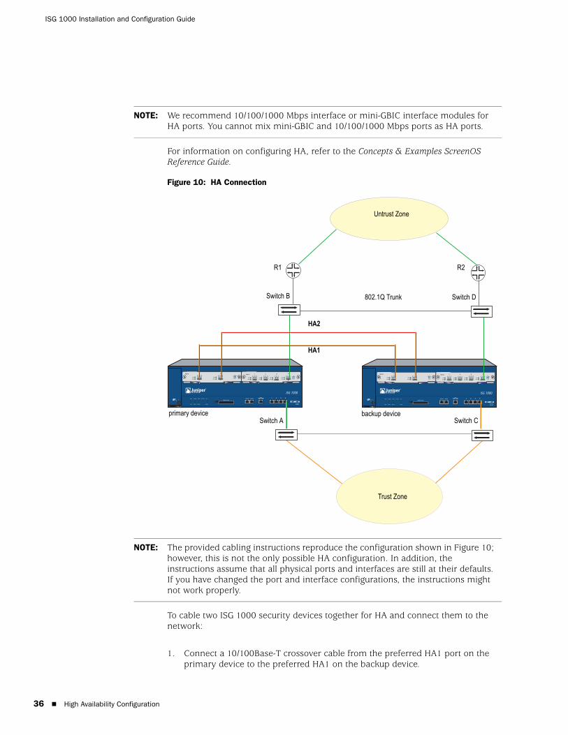
The ISG 1000 device does not have dedicated High Availability (HA) interfaces; however, you can cable and configure two ports per device to behave as an HA interface once the device is running. In an HA configuration, one device is configured as the primary device and the other is configured as the backup. If the primary device fails, the backup device takes over as the primary. Any number and type of interface module port can be used as HA ports. The backup device must have the same interface modules installed and ScreenOS configuration as the primary device for HA to work correctly. Figure 10 illustrates an example of a basic way to cable two ISG 1000 devices for HA.
Keyword Meaning
all Enables all chassis alarms
battery Sets the chassis alarm to sound when a battery fails
fan-failed Sets the chassis alarm to sound when a fan fails
power-failed Sets the chassis alarm to sound when a power supply fails
temperature Sets the chassis alarm to sound when the temperature goes outside the acceptable range
High Availability Configuration 35
ISG 1000 Installation and Configuration Guide
36
For information on configuring HA, refer to the Concepts & Examples ScreenOS Reference Guide.
Figure 10: HA Connection
To cable two ISG 1000 security devices together for HA and connect them to the network:
1. Connect a 10/100Base-T crossover cable from the preferred HA1 port on the primary device to the preferred HA1 on the backup device.
NOTE: We recommend 10/100/1000 Mbps interface or mini-GBIC interface modules for HA ports. You cannot mix mini-GBIC and 10/100/1000 Mbps ports as HA ports.
HA
FLASH
PWR
FAN
ALARM
MOD1
TEMP
MOD2
STATUS
3 44
HA
FLASH
PWR
FAN
ALARM
MOD1
TEMP
MOD2
STATUS
3 44
Untrust Zone
R2
802.1Q Trunk
HA2
HA1
Switch D
R1
Switch B
Trust Zone
Switch A Switch Cprimary device backup device
NOTE: The provided cabling instructions reproduce the configuration shown in Figure 10; however, this is not the only possible HA configuration. In addition, the instructions assume that all physical ports and interfaces are still at their defaults. If you have changed the port and interface configurations, the instructions might not work properly.
High Availability Configuration
2. Connect a 10/100Base-T crossover cable from the preferred HA2 port on the primary device to the preferred HA2 on the backup device.
Configuring HA Ports
3. Set the HA interface by executing the following command on each device, for example:
set interface ethernet2/1 zone haset interface ethernet2/2 zone ha
Master Unit
4. Connect a crossover cable from ethernet1/4 to the switch labeled Switch A.
5. Connect an optical cable from ethernet3/4 to the switch labeled Switch B.
Backup Unit
6. Connect a crossover cable from ethernet1/4 to the switch labeled Switch C.
7. Connect an optical cable from ethernet3/4 to the switch labeled Switch D.
Switches
8. Cable together switches A and C (which are connected to the ethernet1/4 ports).
9. Cable together switches B and D (which are connected to the ethernet3/4 ports).
10. Cable Switch B to the primary router (R1).
11. Cable Switch D to the secondary router (R2).
12. Turn the power switch to the ON position for both ISG 1000 devices.
NOTE: The switch ports must be defined as 802.1Q trunk ports, and the external routers must be able to use either Hot Standby Router Protocol (HSRP) or Virtual Router Redundancy Protocol (VRRP). For the best configuration method, refer to the documentation for your switch or router.
High Availability Configuration 37
ISG 1000 Installation and Configuration Guide
38
Restarting the Device
You may need to restart the device in order to implement new features, such as when you change between route and transparent mode or when you add new license keys.
The following sections describe two methods of restarting the device:
“Restarting the Device with the CLI Reset Command” on page 38
“Restarting the Device with the WebUI” on page 38
Restarting the Device with the CLI Reset CommandTo restart the device with the CLI reset command:
1. Establish a console session with the device as described in “Using a Console Connection” on page 28 or “Using Telnet” on page 30.
At a Windows workstation, the easiset way of opening a console connection is to choose Start > Run and enter telnet ip_address.
The device prompts you for your login and password.
2. If you have not yet changed the default username and password, enter netscreen at both the login and password prompts. (Use lowercase letters only. The login and password fields are both case-sensitive.)
3. At the console prompt, enter:
reset
The device prompts you to confirm the reset:
System reset, are you sure? y/[n]
4. Enter Y.
The device restarts.
Restarting the Device with the WebUITo restart the device with the WebUI:
1. Launch your browser and enter the IP address for the management interface (the default IP address is 192.168.1.1), then press Enter.
The WebUI application displays the login prompt.
2. If you have not yet changed the default username and password, enter netscreen at both the login and password prompts. (Use lowercase letters only. The login and password fields are both case-sensitive.)
3. In the WebUI, choose:
Configuration > Update > ScreenOS/Keys
Restarting the Device
4. Click Reset.
An alert box prompts you to confirm that you want to reset the device.
5. Click OK.
The device resets. Also, an alert box prompts you to leave your browser open for a few minutes and then log back into the device.
Restarting the Device 39
ISG 1000 Installation and Configuration Guide
40
Resetting a Device to Factory Defaults
If you lose the admin password, or you need to clear the configuration of your device, you can reset the device to its factory default settings. Resetting the device destroys any existing configurations and restores access to the device.
You can restore the device to its default settings using one of these methods:
Using the device serial number
Using the CLI unset all command
The following sections describe how to use these methods to reset the device to its factory defaults.
Device Serial NumberTo use the device serial number to reset the device to its factory defaults:
1. Start a Console session as described in “Using a Console Connection” on page 27.
2. At the Login prompt, enter the device serial number.
3. At the Password prompt, enter the serial number again. The following message appears:
!!! Lost Password Reset !!! You have initiated a command to reset the device to factory defaults, clearing all current configuration and settings. Would you like to continue? y/[n]
4. Press the y key. The following message appears:
!! Reconfirm Lost Password Reset !! If you continue, the entire configuration of the device will be erased. In addition, a permanent counter will be incremented to signify that this device has been reset. This is your last chance to cancel this command. If you proceed, the device will return to factory default configuration, which is: device IP: 192.168.1.1; username: netscreen, password: netscreen. Would you like to continue? y/[n]
5. Press the y key to reset the device.
The system now resets and returns to the login prompt; the default login name and password are both reset to netscreen.
CAUTION: Resetting the device deletes all existing configuration settings and disables all existing firewall and VPN services.
NOTE: By default, the device recovery feature is enabled. You can disable it by entering the CLI unset admin device-reset command. Also, if the security device is in FIPS mode, the recovery feature is automatically disabled.
Resetting a Device to Factory Defaults

unset allTo use the CLI unset all command, you will need to know the login name and password. To reset the device to its factory defaults:
1. Start a Console session as described in “Using a Console Connection” on page 27, then log in.
2. At the command prompt, enter unset all. The following message is displayed:
Erase all system config, are you sure y/[n] ?
3. Press y
4. Enter reset. Press n for the first question and y for the second question:
Configuration modified, save? [y]/nSystem reset, are you sure? y/[n]
The system now resets and returns to the login prompt; the default login name and password are both reset to netscreen.
Resetting a Device to Factory Defaults 41

ISG 1000 Installation and Configuration Guide
42
Resetting a Device to Factory Defaults
Chapter 4
Servicing the Device
This chapter describes service and maintenance procedures for an ISG 1000 device. It includes the following sections:
“Required Tools and Parts” on page 44
“Interface Modules” on page 44
“Power Supply Units” on page 46
“Fan Tray” on page 47
“Fan-Tray Filter” on page 48
“Cables and Transceivers” on page 49
“Security Modules” on page 51
NOTE: For safety warnings and instructions, refer to the Juniper Networks Security Products Safety Guide. The guide warns you about situations that could cause bodily injury. Before working on any equipment, you should be aware of the hazards involved with electrical circuitry and familiar with standard practices for preventing accidents.
43
ISG 1000 Installation and Configuration Guide
44
Required Tools and Parts
To replace some components on an ISG 1000 device, you need the following tools and parts:
Electrostatic bag or antistatic mat
Electrostatic discharge (ESD) grounding wrist strap
Phillips screwdriver, 1/8-inch
Interface Modules
This section provides instructions on how to service the interface modules on an ISG 1000 device.
Remove Interface ModuleTo remove an interface module from a slot:
1. Unscrew the thumbscrews on each side of the interface module.
2. With your thumbs, pull the locking levers out.
3. Grip the levers, then gently slide the module straight out (Figure 11).
4. If you are not reinstalling an interface module into the empty slot, install a blank faceplate over the slot to maintain proper airflow.
Figure 11: Remove Interface Module
WARNING: When removing interface modules, be sure that the power is in the OFF position.
Required Tools and Parts
Insert Interface ModuleTo insert an interface module into a module slot:
1. Align the side edges of the module with the grooves in the side walls of the slot (Figure 12).
Figure 12: Insert Interface Module
2. Slide the module in until it is forced to stop.
3. With your thumbs, push in the locking levers to secure the module (Figure 13).
Figure 13: Lock Interface Module
4. Secure the thumbscrews on each side of the interface module.
WARNING: When inserting interface modules, be sure that the power is in the OFF position.
WARNING: Pushing the latch before it contacts the ridge on the slot wall sets the locking tab prematurely and seats the interface module improperly.
Interface Modules 45
ISG 1000 Installation and Configuration Guide
46
Power Supply Units
This section provides instructions on servicing the power supply units (PSUs) available on an ISG 1000.
DC Power Supply ReplacementTo replace the DC PSU:
1. Turn off the current and the PSU.
2. Loosen the three retaining screws on the terminal block.
3. Remove the feed wires.
4. Turn the thumbscrews counterclockwise to release the PSU.
5. Gripping the handle, gently pull out the PSU.
6. Insert the new PSU into the bay.
7. Secure the PSU by tightening the thumbscrews clockwise.
8. Insert the 0V DC (positive voltage) return wire into the COM connector and the -48V DC power-feed wire into the -48V connector, then ground the wire into the GND connector.
9. Fasten the screws over the connectors.
10. Press the power switch to the ON position.
AC Power Supply ReplacementTo replace an AC PSU:
1. Press the power switch to the OFF position
2. Unplug the cord from the PSU.
3. Loosen the thumbscrews on the power supply by turning them counterclockwise to release the PSU.
4. Lift the handle and pull straight out.
5. Insert the new PSU into the slot.
6. Fasten the PSU to the device by tightening the thumbscrews clockwise.
WARNING: You must shut off current to the DC feed wires leading to the PSU. Also, make sure that the ON/OFF switch on the PSU is in the OFF position.
Power Supply Units
7. Connect the female end of a standard power cord to the male connector on the back of the power supply.
8. Press the power switch to the ON position.
Fan Tray
You need to replace the fan module when a failure occurs. When fan failure occurs, the FAN LED glows red, and the device generates an event alarm and an SNMP trap.
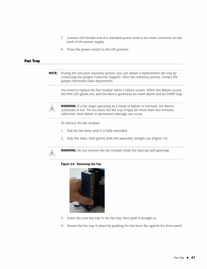
To remove the fan module:
1. Pull the fan lever until it is fully extended.
2. Grip the sides, then gently slide the assembly straight out (Figure 14).
Figure 14: Removing the Fan
3. Insert the new fan tray in the fan bay, then push it straight in.
4. Secure the fan tray in place by pushing the fan lever flat against the front panel.
NOTE: During the one-year warranty period, you can obtain a replacement fan tray by contacting the Juniper Customer Support. After the warranty period, contact the Juniper Networks Sales department.
WARNING: If a fan stops operating as a result of failure or removal, the device continues to run. Do not leave the fan tray empty for more than two minutes; otherwise, heat failure or permanent damage can occur.
WARNING: Do not remove the fan module while the fans are still spinning.
Fan Tray 47
ISG 1000 Installation and Configuration Guide
48
Fan-Tray Filter
Before you replace the fan filter, make sure you have the following tools:
Flashlight or other light source
18-inch wooden ruler or at least a 45-centimeter length of wooden dowel
To replace the fan tray filter:
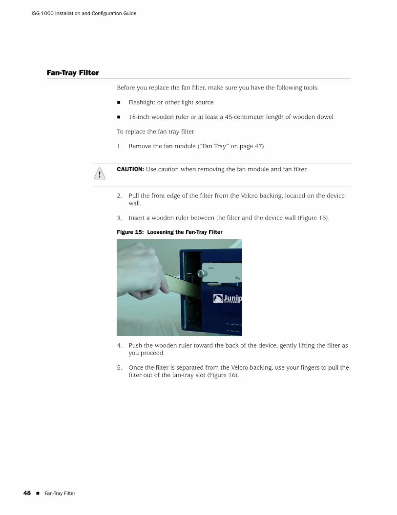
1. Remove the fan module (“Fan Tray” on page 47).
2. Pull the front edge of the filter from the Velcro backing, located on the device wall.
3. Insert a wooden ruler between the filter and the device wall (Figure 15).
Figure 15: Loosening the Fan-Tray Filter
4. Push the wooden ruler toward the back of the device, gently lifting the filter as you proceed.
5. Once the filter is separated from the Velcro backing, use your fingers to pull the filter out of the fan-tray slot (Figure 16).
CAUTION: Use caution when removing the fan module and fan filter.
Fan-Tray Filter
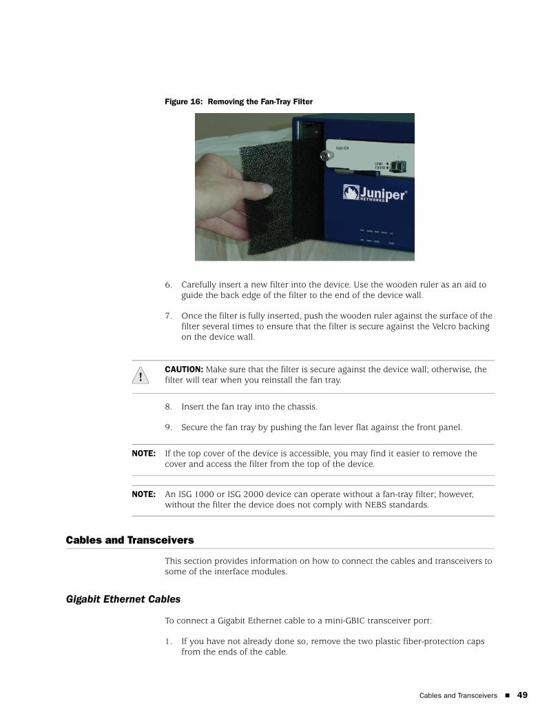
Figure 16: Removing the Fan-Tray Filter
6. Carefully insert a new filter into the device. Use the wooden ruler as an aid to guide the back edge of the filter to the end of the device wall.
7. Once the filter is fully inserted, push the wooden ruler against the surface of the filter several times to ensure that the filter is secure against the Velcro backing on the device wall.
8. Insert the fan tray into the chassis.
9. Secure the fan tray by pushing the fan lever flat against the front panel.
Cables and Transceivers
This section provides information on how to connect the cables and transceivers to some of the interface modules.
Gigabit Ethernet Cables
To connect a Gigabit Ethernet cable to a mini-GBIC transceiver port:
1. If you have not already done so, remove the two plastic fiber-protection caps from the ends of the cable.
CAUTION: Make sure that the filter is secure against the device wall; otherwise, the filter will tear when you reinstall the fan tray.
NOTE: If the top cover of the device is accessible, you may find it easier to remove the cover and access the filter from the top of the device.
NOTE: An ISG 1000 or ISG 2000 device can operate without a fan-tray filter; however, without the filter the device does not comply with NEBS standards.
Cables and Transceivers 49
ISG 1000 Installation and Configuration Guide
50
2. Hold the cable connector between your thumb and forefinger, with your thumb on top and your forefinger underneath. (Do not press the release on top of the connector.)
3. Slide the connector into the transceiver port until it clicks into place. Because the fit is close, you might have to apply some force to insert the connector. To avoid damaging the connector, apply force evenly and gently.
To remove the cable from the transceiver port:
1. Make sure the transceiver latch is in a secured locked position (the latch is flat against the front of the transceiver). Otherwise, when you attempt to remove the cable, the transceiver might come out with the cable still attached.
Figure 17: Transceiver Latch
2. Hold the connector between your thumb and forefinger, with your thumb on top and your forefinger underneath.
3. Using your thumb, press the connector release down, then forward. This action loosens the connector from the transceiver port.
4. Gently but firmly pull the clip from the transceiver port.
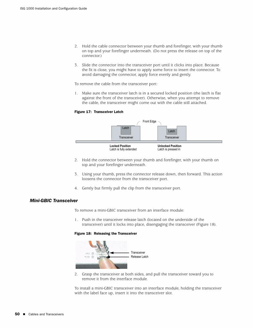
Mini-GBIC Transceiver
To remove a mini-GBIC transceiver from an interface module:
1. Push in the transceiver release latch (located on the underside of the transceiver) until it locks into place, disengaging the transceiver (Figure 18).
Figure 18: Releasing the Transceiver
2. Grasp the transceiver at both sides, and pull the transceiver toward you to remove it from the interface module.
To install a mini-GBIC transceiver into an interface module, holding the transceiver with the label face up, insert it into the transceiver slot.
Locked Position Latch is fully extended
Unlocked PositionLatch is pressed in
LatchLatch
Transceiver Transceiver
Front Edge
TransceiverRelease Latch
Cables and Transceivers
Security Modules
Security modules are high-performance-processing subdevices that increase the performance of the ISG 1000 for high CPU-usage services, such as Intrusion Detection and Prevention (IDP).
To install or remove a security module:
1. Remove the top cover from the device. (Remove the three screws located on the sides and the back of the top cover.)
2. Insert the security module into an empty slot, starting with the slot closest to the front.
3. After inserting the security module into the slot, use the insertion/extraction handles to correctly install the module into the slot.
Once all of the security modules are installed, replace the cover, install the device in the rack, connect the power cords, and then turn on the power.
CAUTION: Before you install or remove a security module, make sure the power is OFF, the power cords are removed, and the device is placed on a stable table.
Security Modules 51

ISG 1000 Installation and Configuration Guide
52
Security Modules
Appendix A
Specifications
This appendix provides general device specifications for the ISG 1000:
“Physical” on page 53
“Electrical” on page 54
“Environmental” on page 54
“Certifications” on page 54
“Connectors” on page 56
Physical
Table 7provides the physical specifications for the ISG 1000.
Table 7: ISG 1000 Physical Specifications
Description Value
Chassis dimensions
44.45 cm x 43.82 cm x 13.34 cm (17.5 inches x 17.25 inches x 5.25 inches)
Device weight 16.3 kilograms (36 lbs) with two modules and PSU
Physical 53
ISG 1000 Installation and Configuration Guide
54
Electrical
Table 8 provides the electrical specifications for the ISG 1000.
Table 8: ISG 1000 Electrical Specifications
Environmental
Table 9 shows the environmental specifications for the ISG 1000.
Table 9: ISG 1000 Environmental Tolerance
Item Specification
AC voltage 100 - 240 VAC +/- 10%
AC power 250 watts
AC input frequency 50-60 Hz
DC voltage -48 VDC
DC power 250 watts
Fuse Rating DC PS: 10 amps / 250 volts; AC PS: 56.3 amps / 250 volts
WARNING: Certain ports on the device are designed for use as intrabuilding (within-the-building) interfaces only (Type 2 or Type 4 ports as described in GR-1089-CORE, Isssue 4) and require isolation from the exposed outside plant (OSP) cabling. To comply with NEBS requirements and protect against lightning surges and commercial power disturbances, the intrabuilding ports must not be metallically connected to interfaces that connect to the OSP or its wiring. The intrabuilding ports on the device are suitable for connection to intrabuilding or unexposed wiring or cabling only. The addition of primary protectors is not sufficient protection for connecting these interfaces metallically to OSP wiring.
CAUTION: To comply with intrabuilding lightning and surge requirements, intrabuilding wiring must be shielded, and the shield for the wiring must be grounded at both ends.
Description Value
Altitude No performance degradation to 10,000 feet (3,048 meters)
Relative humidity Normal operation ensured in relative humidity range of 10 to 90 percent, noncondensing
Temperature Normal operation ensured in temperature range of 32°F (0°C) to 122°F (50°C)
Electrical
Certifications
Table 10 provides the certifications available for the ISG 1000.
Table 10: ISG 1000 Certifications
Certification Type Certification Name
NEBSa
a.An ISG 1000 or ISG 2000 device can operate without a fan-tray filter; however, without the filter the device does not comply with NEBS standards.
NEBS Level 3
GR-63-Core: NEBS, Environmental Testing
GR-1089-Core: EMC and Electrical Safety for Network Telecommunications Equipment
Safety CAN/CSA-C22.2, No. 60950-1-03/UL 60950-1, EN 60950-1, IEC 60950-1
EMI FCC class A, CE class A, C-Tick, VCCI Class A
Certifications 55
ISG 1000 Installation and Configuration Guide
56
Connectors
Figure 19 shows the location of the pins on the RJ-45 connector.
Figure 19: RJ-45 Pinouts
Table 11 lists the RJ-45 connector pinouts.
Table 11: RJ-45 Connector Pinouts
Pin Name I/O Description
1 RTS Out O Request To Send
2 DTR Out O Data Terminal Ready
3 TxD O Transmit Data
4 GND NA Chassis Ground
5 GND NA Chassis Ground
6 RxD I Receive Data
7 DSR I Data Set Ready
8 CTS I Clear To Send
1 2 3 4 5 6 7 8
Connectors
Figure 20 shows the location of the pins on the DB-9 female connector.
Figure 20: DB-9 Female Connector
Table 12 provides the DB-9 connector pinouts.
Table 12: DB-9 Connector Pinouts
The Mini-Gigabit transceivers are compatible with the IEEE 802.3z Gigabit Ethernet standard, and the 10Gbase-R transceivers are compatible with the IEEE 802.3ae standard. Table 13 lists media types and distances for the different types of interfaces used in the ISG 1000.
Table 13: Interface Media Types for the Mini-Gigabit and 10Gigabit XFP Transceivers
Pin Name I/O Description
1 DCD I Carrier Detect
2 RxD I Receive Data
3 TxD O Transmit Data
4 DTR O Data Terminal Ready
5 GND NA Signal Ground
6 DSR I Data Set Ready
7 RTS O Request To Send
8 CTS I Clear To Send
9 RING I Ring Indicator
Standard Media Type Maximum Distance (in Meters)
1000Base-SX 50/125 m multimode fiber 500
50/125 m multimode fiber 550
62.5/125 m multimode fiber 220
62.5/125 m multimode fiber 275
1000Base-LX 50/125 m multimode fiber 550
62.5/125 m multimode fiber 550
9/125 single-mode fiber 10,000
100Base-TX Category 5 and higher UTP cable 100
10Gbase-SR 850nm multimode fiber 26-300
10Gbase-LR 1310nm single-mode fiber 10,000
μ
μ
μ
μ
μ
μ
μ
Connectors 57

ISG 1000 Installation and Configuration Guide
58
Connectors
Index
Ccablingnetwork interfaces.....................................................23power supply.............................................................23
chassis alarm configuration ..............................................35configuration
admin name and password .......................................30administrative access ................................................31date and time ............................................................31default route..............................................................32host and domain name .............................................32management services................................................33
DDC power supply ..............................................................16dialup connection .............................................................29
Ffactory defaults, resetting to..............................................40fan
LED ...........................................................................12tray............................................................................16
fan filter replacement .......................................................48
Ggigabit Ethernet cable
connecting.................................................................49disconnecting ............................................................50
Hhigh availability (HA)
cabling.................................................................35–40LED ...........................................................................11overview....................................................................35
Iinstalling modules.............................................................16interface modules .............................................................14
LLEDs .................................................................................11logging on.........................................................................29
Mmanagement
through a console ......................................................27through a Telnet connection......................................28
through the WebUI ....................................................29managing
through WebUI ..........................................................38mini-GBIC transceiver, replacing .......................................50modem.............................................................................29modules
high availability .........................................................16LEDs..........................................................................12removing ...................................................................44
NNEBS certification .............................................................55NEBS warning...................................................................21
Ppower supply unit (PSU)
AC replacement .........................................................46DC replacement.........................................................46overview....................................................................16
Rresetting to factory defaults...............................................40restarting the device .........................................................38
Ssafety guidelines ...............................................................18serial connection...............................................................29setting
policies ......................................................................34Trust IP address.........................................................33Untrust IP address .....................................................34
WWebUI, using ....................................................................38
Index 59

ISG 1000 Installation and Configuration Guide
60
Index