Embed Size (px)
Citation preview
Juniper Networks ISG 1000 and ISG 2000 Security Policy 1
FIPS 140-2 SECURITY POLICY Juniper Networks
ISG 1000 and ISG 2000 HW P/N NS-ISG-1000, NS-ISG-2000
FW Version ScreenOS 5.4.0r4-5.4.0r19
Document # 093-1803-000
Juniper Networks ISG 1000 and ISG 2000 Security Policy 2
Copyright Notice
Copyright © 2010 Juniper Networks, Inc. May be reproduced only in its original entirety [without revision].
Juniper Networks, the Juniper Networks logo, NetScreen, NetScreen Technologies, GigaScreen, and the NetScreen logo are registered trademarks of Juniper Networks, Inc. SSG 520M, SSG 550M, NetScreen-5XP, NetScreen-5XT, NetScreen-25, NetScreen-50, NetScreen-100, NetScreen-204, NetScreen-208, NetScreen-500, NetScreen-5200, NetScreen-5400, NetScreen-Global PRO, NetScreen-Global PRO Express, NetScreen-Remote Security Client, NetScreen-Remote VPN Client, NetScreen-IDP 10, NetScreen-IDP 100, NetScreen-IDP 500, GigaScreen ASIC, GigaScreen-II ASIC, and NetScreen ScreenOS are trademarks of Juniper Networks, Inc. All other trademarks and registered trademarks are the property of their respective companies.
Juniper Networks, Inc.
ATTN: General Counsel
1194 N. Mathilda Ave.Sunnyvale, CA 95014
FCC Statement The following information is for FCC compliance of Class A devices: This equipment has been tested and found to comply with the limits for a Class A digital device, pursuant to part 15 of the FCC rules. These limits are designed to provide reasonable protection against harmful interference when the equipment is operated in a commercial environment. The equipment generates, uses, and can radiate radio-frequency energy and, if not installed and used in accordance with the instruction manual, may cause harmful interference to radio communications. Operation of this equipment in a residential area is likely to cause harmful interference, in which case users will be required to correct the interference at their own expense.
The following information is for FCC compliance of Class B devices: The equipment described in this manual generates and may radiate radio-frequency energy. If it is not installed in accordance with NetScreen’s installation instructions, it may cause interference with radio and television reception. This equipment has been tested and found to comply with the limits for a Class B digital device in accordance with the specifications in part 15 of the FCC rules. These specifications are designed to provide reasonable protection against such interference in a residential installation. However, there is no guarantee that interference will not occur in a particular installation.
If this equipment does cause harmful interference to radio or television reception, which can be determined by turning the equipment off and on, the user is encouraged to try to correct the interference by one or more of the following measures:
Reorient or relocate the receiving antenna. Increase the separation between the equipment and receiver. Consult the dealer or an experienced radio/TV technician for help. Connect the equipment to an outlet on a circuit different from that to which the receiver is connected.
Caution: Changes or modifications to this product could void the user's warranty and authority to operate this device.
Disclaimer THE SOFTWARE LICENSE AND LIMITED WARRANTY FOR THE ACCOMPANYING PRODUCT ARE SET FORTH IN THE INFORMATION PACKET THAT SHIPPED WITH THE PRODUCT AND ARE INCORPORATED HEREIN BY THIS REFERENCE. IF YOU ARE UNABLE TO LOCATE THE SOFTWARE LICENSE OR LIMITED WARRANTY, CONTACT YOUR NETSCREEN REPRESENTATIVE FOR A COPY.
Juniper Networks ISG 1000 and ISG 2000 Security Policy 3
TABLE OF CONTENTS A. Scope of Document .................................................................................................................................. 4 B. Security Level ........................................................................................................................................... 4 C. Roles and Services .................................................................................................................................. 5 D. Interfaces .................................................................................................................................................. 8 E. Setting FIPS Mode ................................................................................................................................... 9 F. Other Parameters ................................................................................................................................... 12 G. Physical Security Policy ......................................................................................................................... 16 I. Critical Security Parameter (CSP) Definitions ........................................................................................ 16 J. Public Key Definitions ............................................................................................................................. 18 K. Matrix Creation of Critical Security Parameter (CSP) versus the Services (Roles & Identity) .......... 18 L. Definitions List ......................................................................................................................................... 21

Juniper Networks ISG 1000 and ISG 2000 Security Policy 4
A. Scope of Document The Juniper Networks ISG 1000 and ISG 2000 (hereafter referred to as the “ISG series”) are Internet security devices that integrate firewall, virtual private networking (VPN), and traffic shaping functions.
Through the VPN, the ISG series devices provide the following:
• IPSec standard security • Triple-DES and Advanced Encryption Standard (AES) key management • Manual and automated IKE • Use of RSA and DSA certificates
The ISG series also provide an interface for an operator to configure or set policies through the Console or Network ports. For initial configuration, the operator must directly connect a VT-100 terminal or a non-networked device that can emulate a VT-100 terminal to the Console port via a serial cable. The general components of the ISG series include firmware and hardware. The main hardware components consist of a main processor, memory, flash, ASIC (Jupiter version II), 10/100 Mbps ethernet interface, GBIC network interface, console interface, backplane, redundant power supply and fan tray. The entire case is defined as the cryptographic boundary of the module. The NetScreen ISG series physical configuration is defined as a multi-chip standalone module.
NOTE: Unless explicitly stated otherwise, the text that follows applies to both the ISG 1000 and ISG 2000. B. Security Level The ISG series meets the overall requirements applicable to Level 2 security of FIPS 140-2.
Table 1: Module Security Level Specification
Security Requirements Section Level
Cryptographic Module Specification 3 Cryptographic Module Ports and Interfaces
2
Roles, Services, and Authentication 2 Finite State Model 2 Physical Security 2 Operational Environment N/A Cryptographic Key Management 2 EMI/EMC 2 Self-Tests 2 Design Assurance 2 Mitigation of Other Attacks N/A
Juniper Networks ISG 1000 and ISG 2000 Security Policy 5
C. Roles and Services The ISG series support five distinct roles:
• Cryptographic Officer (Root): The device allows one Crypto-Officer. This role is assigned to the first operator who logs on to the device using the default admin name and password (netscreen, netscreen). Only the Crypto-Officer can create other administrators, and change the device to operate in FIPS mode.
• User (Admin): This role can configure specific security policies. These policies provide the device with information on how to operate. For example, configuring access policies and VPN encryption with Triple-DES). This role does not have the ability to create other administrators..
• Read-Only User (Admin): This role can only perform a limited set of services to retrieve information or status. This role cannot perform services to configure the device.
• VSYS User: This role has the same operations as the User, listed previously, except that a VSYS User only operates within a particular virtual system. See the NetScreen Concepts & Examples ScreenOS Reference Guide for more information about virtual systems.
• VSYS Read-Only User: This role has the same operations as the Read-Only User, listed previously, except that a VSYS Read-Only User only operates within a particular virtual system. See the NetScreen Concepts & Examples ScreenOS Reference Guide for more information about virtual systems.
The module allows concurrent Admin users, either User or Read-Only User roles. The ISG series provides the following services for each role:
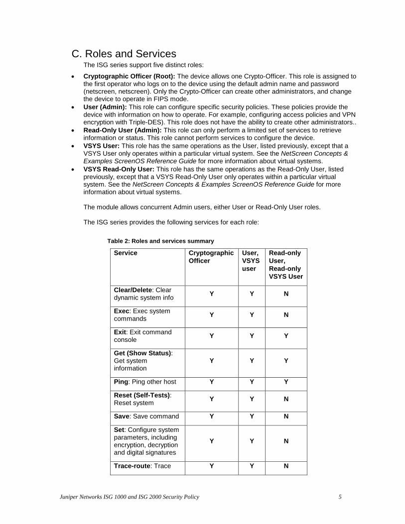
Table 2: Roles and services summary
Service Cryptographic Officer
User, VSYS user
Read-only User, Read-only VSYS User
Clear/Delete: Clear dynamic system info Y Y N
Exec: Exec system commands Y Y N
Exit: Exit command console Y Y Y
Get (Show Status): Get system information
Y Y Y
Ping: Ping other host Y Y Y
Reset (Self-Tests): Reset system Y Y N
Save: Save command Y Y N
Set: Configure system parameters, including encryption, decryption and digital signatures
Y Y N
Trace-route: Trace Y Y N

Juniper Networks ISG 1000 and ISG 2000 Security Policy 6
route
Unset: Unconfigure system parameters Y Y N
• Clear/Delete: Clear dynamic system info
• Exec: Exec system commands
• Exit: Exit command console
• Get (Show Status): Get system information
• Ping: Ping other host
• Reset (Self-Tests): Reset system
• Save: Save command
• Set: Configure system parameters
• Trace-route: Trace route
• Unset: Unconfigure system parameters
The ISG series supports both role-based and identity-based authentication.
• All roles can be authenticated locally (within the ISG series device); optionally, the module supports authentication via a RADIUS server for only the User role. Authentication by use of the RADIUS server is viewed as role-based authentication; all other methods of authentication are identity-based.
• All other forms of authentication (local database) are classified as identity-based. • The module supports identity-based authentication for the Cryptographic Officer Role
(local database), the User Role (local database), and the Read-Only Role (local database).
• User names and passwords are case-sensitive. The password consists of at least six alphanumeric characters. Since there are 26 uppercase letters, 26 lowercase letters, and 10 digits, the total number of available characters is 62. The probability of someone guessing a password is 1/(626) = 1/56,800,235,584 , which is far less than a 1/1,000,000 random success rate. If three login attempts from the console fail consecutively, the console will be disabled for one minute. If three login attempts from Telnet or the WebUI (through VPN with AES encryption) fail consecutively, any login attempts from that source will be dropped for one minute.
• If there are multiple login failure retries within one minute and since the user is locked out after three contiguous login failures, the random success rate for multiple retries is 1/(626) + 1/ 626) + 1/(626) = 3/(626), which is far less than 1/100,000.
• In order for authentication data to be protected against disclosure, substitution and modification, passwords are not echoed during entry.
• The ISG series enforce both identity-based and role-based authentication. Based on their identity, the operator assumes the correct role.
• Operators must be authenticated using user names and passwords. Authentication will occur locally. As an option, the user can be authenticated via a RADIUS server. The RADIUS server provides an external database for user role administrators. The ISG acts

Juniper Networks ISG 1000 and ISG 2000 Security Policy 7
as a RADIUS proxy, forwarding the authentication request to the RADIUS server. The RADIUS server replies with either an accept or reject message. See the log for authenticated logins. The RADIUS shared secret must be at least six characters.
• All logins through a TCP connection disconnect upon three consecutive login failures and an alarm is logged.
Juniper Networks ISG 1000 and ISG 2000 Security Policy 8
D. Interfaces The ISG series devices provide a number of interfaces:
• The Netscreen - ISG 1000 has four fixed 10/100/1000 interfaces(Data Input, Data Output, Control Input, Status Output). Connect the ports using a twisted pair cable with RJ-45 connectors.
• The NetScreen-ISG 2000 has four interface module bays. The NetScreen-ISG 1000 has two module bays. Each interface module has two, four, or eight ports, and each port has a pair of LEDs.
• The 10/100 Mbps interface module is appropriate for a 10/100 Base-T LAN with an option of four or eight ports.
• The mini-GBIC interface module provides connectivity to fiber-based, gigabit Ethernet LANs(Data Input, Data Output, Control Input, Status Output). Connect the module using an optical single mode or multi mode cable. The NetScreen ISG devices have two mini-GBIC interfaces (labelled 1, and 2). These interfaces are the network ports. Each port has 2 link lights (LEDs) to indicate the port status. The top LED indicates the link status. If the LED is on, this means the link is up. If the LED is off, this means the link is down. The bottom LED indicates the link activity. If the LED is on and is blinking, this means the port is active (transmitting/receiving data). If the LED is off, this means the port is inactive.
• The NetScreen-ISG offers three management interfaces which provide Data Input, Data Output, Control Input, Status Output:
o Console port: RJ-45. This port allows initial access to the Command Line Interface (CLI).
o Modem port: RJ-45. Disabled in FIPS mode. o MGT port: 10/100 Mbps ethernet for management traffic. It has 2 link lights
(LEDs) to indicate the port status. The right LED indicates the link status. If the LED is on, this means the link is up. If the LED is off, this means the link is down. The left LED indicates the ethernet activity. If the LED is on and is blinking, this means the port is active (transmitting/receiving data). If the LED is off, this means the port is inactive.
• HA port: There are no dedicated High Availability (HA) interfaces on the NetScreen ISG devices. The administrator must select and configure the HA ports once the system is running.
• Compact flash interface for a memory flash card • Fan Module: The NetScreen ISG devices have a three-fan module, which you can access
on the left front side of the chassis. The fan tray has a status LED: Illuminates solid green when the fan is operational, and is dark when it is not operational.
• Power interface, AC or DC. • The management module has LED Dashboard consisting eight types of indicators:
o One Power status LED: Illuminates solid green when the power is supplied to the NetScreen-ISG.
o System Alarm LED: Illuminates red when a critical alarm occurs, such as a hardware or software failure, or a firewall attack; illuminates amber when a major alarm occurs, such as "low memory;" is dark when there are no alarms.
o One Temperature LED: Illuminates green when the temperature is within safety range; illuminates amber when the temperature is outside normal alarm range (>132ºF or 56º) and is red when temperature is ourside server alarm range (>150ºF or 66º)
o One System status LED: Illuminates blinking green when the module is operational, or amber when the unit is booting up.
o HA LED: Illuminates green if the unit is the master, amber if the unit is the slave, and is dark if HA is not configured.
o Fan Status LED: Illuminates green when all fans are functioning properly; illuminates red when one of more fans failed or fan subsystem is not receiving power.
Juniper Networks ISG 1000 and ISG 2000 Security Policy 9
o Three Module status LED (MOD1, MOD2 & MOD3): Illuminates solid green when the security module is installed, or is off when the module is empty.
o Compact Flash LED: Illuminates green if the compact flash card is installed in the compact flash slot, blinking green if the compact flash card is active, and is dark if the slot is empty.
E. Setting FIPS Mode
By default, the module is in non-FIPS mode on the first power-up.
Prior to placing the device in FIPS mode, the administrator must load the Juniper firmware authentication DSA public key, imagekey.cer, using the save image-key CLI command. When this public key is present on the device, the integrity and authenticity of the firmware is checked at system start and when firmware is loaded. If the DSA signature appended to the firmware is verified, the device allows it to be loaded.
If the device is not already running a FIPS validated version of the firmware, the administrator should load it using the save software CLI command. Loading a new version of firmware completely replaces any existing firmware.
Enable FIPS mode using the set FIPS-mode enable command. The module is automatically zeroized when toggling between FIPS and non-FIPS modes of operation, which resets the configuration back to factory default values and restarts the module. It is suggested that the module's configuration be saved prior to switching modes.
To check whether the device is in FIPS mode, enter the get system CLI command: ns-> get system Product Name: isg2000 Serial Number: 0099122004000991, Control Number: 00000000, Mode: FIPS Hardware Version: 0110(0)-(12), FPGA checksum: 00000000, VLAN1 IP (0.0.0.0) Software Version: 5.4.0r4.0, Type: Firewall+VPN Base Mac: 0010.db90.f770 File Name: isg2000.5.4.0r4.0, Checksum: 48e3d429
The current mode appears on the second line of the output.
1. The module can be set to FIPS mode only through the CLI. To set the module to FIPS mode, execute the set FIPS-mode enable command through the CLI.
The set FIPS-mode enable command performs the following:
• Disables administration via SSL • Disables loading and output of configuration files from the TFTP server • Disables the NetScreen-Global PRO reporting agent • Disables the SNMP Read-Write community • Disables debug service • Disables the Modem port • Enforces management via Telnet, HTTP (WebUI) and NetScreen Security Manager
(NSM) only through a VPN with 256-bit AES encryption • Enforces SSHv2 management traffic to use only Triple-DES. (SSHv1 is disabled.) • Disables the MD5 and DES algorithms
2. Confirm the save command. 3. Confirm the reset command.
Note the following:
• Configure the HA encryption key before using the HA link.

Juniper Networks ISG 1000 and ISG 2000 Security Policy 10
• Management via Telnet, HTTP (WebUI) and NSM is only allowed through a VPN tunnel with 256-bit AES encryption.
• DSA-signed firmware image cryptographic strength analysis: the firmware is signed by a well-protected 1024 bit modulus DSA private key, which provides 80 bits of security. The generated signature is attached to the firmware. In order for the device to accept an authorized image, the image has to have a correct signature.
• The image download takes at least 23 seconds, so there can be no more than 3 download tries within one minute. Therefore, the random success rate for multiple retries is 1/(2 320) + 1/(2 320) + 1/(2 320) = 3/(2 320), which is far less than 1/100,000.
• The ISG series does not employ a maintenance interface or have a maintenance role. • When in FIPS mode, the WebUI of the NetScreen ISG series only displays options
that comply with the requirements of FIPS 140-2. • The output data path is logically disconnected from the circuitry and processes that
perform key generation or key zeroization. • The ISG series provides a Show Status service via the GET service. • The ISG series implements the following power-up self-tests:
Device Specific Self-Tests:
– Boot ROM firmware self-test is via DSA signature (Firmware Integrity Test) – SDRAM read/write check – FLASH test
Algorithm Self-Tests:
– Triple-DES, CBC mode, encrypt/decrypt KAT – SHA-1 KAT – RSA (encrypt/decrypt and sign/verify) KAT – DSA Sign/Verify pairwise consistency test – AES, CBC mode, encrypt/decrypt KAT – HMAC SHA-1 KAT – ANSI X9.31 DRNG KAT – DH exponentiation test
• The ISG series implements the following conditional tests: – DRNG continuous test (both approved and non-approved RNG’s) – DSA pairwise consistency test – RSA pairwise consistency test – Bypass test – Firmware download DSA signature test (Software Load Test) – DH pairwise consistency test
• On failure of any power-up self-test, the module enters and stays in either the Algorithm Error State, or Device specific error state, depending on the self-test failure. The console displays error messages and the status LED flashes red. It is the responsibility of the Crypto-Officer to return the module to Juniper Networks for further analysis.
• On failure of any conditional test, the module enters and stays in a permanent error state, depending on the type of failure: Bypass test failure, DH exponentiation test failure, RNG continuous test, Software load test, DSA pair-wise test failure, or RSA pair-wise agreement test failure. The console displays error messages and the status
Juniper Networks ISG 1000 and ISG 2000 Security Policy 11
LED flashes red. It is the responsibility of the Crypto-Officer to return the module to Juniper Networks for further analysis.
• If the device enters one of the permanent error states as a result of a self-test failure, the module is halted. No traffic is processed after this occurs. The module must have power cycled to return to operation. A self-test error message has the following format: “XXX test failed: error code N”.
• In FIPS mode, the operator is prevented from configuring a VPN whose strength is stronger then the security provided by the management connection:
o For sessions via a directly connected serial cable, no strength restriction is applied.
o For remote SSH connections (which are protected by Triple-DES encryption), the strength of the management connection is considered to 112 bits. Therefore, the operator is prevented from configuring a VPN whose encryption algorithm has a strength greater than 112 bits, e.g. 128, 192 or 256 bit AES.
o For remote telnet, WebUI or NSM connections, no strength restriction is applied, since these connections are already forced to pass through a 256-bit AES VPN.
Juniper Networks ISG 1000 and ISG 2000 Security Policy 12
F. Other Parameters Note the following:
• Firmware can be loaded through Trivial File Transfer Protocol (TFTP), where a firmware load test is performed via a DSA signature. Firmware may only be loaded in non-FIPS mode, as this service is disabled in FIPS mode.
• Keys are generated using a FIPS approved pseudo random number generator per ANSI X9.31, Appendix C.
• For every usage of the module’s random number generator, a continuous RNG self-test is performed. Note that this is performed on both the FIPS approved RNG and non-FIPS approved RNG.
• A separate session is assigned to each successful administrator login.
The first time an operator logs on to the module, the operator uses the default user name and password which is netscreen, netscreen. This user is assigned the Crypto-Officer role.
• The Crypto-Officer is provided with the same set of services as the user, with four additional services:
– set admin and unset admin allow the Crypto-Officer to create a new user, change a current user’s user name and password, or delete an existing user.
– set FIPS enable and unset FIPS enable allow the Crypto-Officer to switch between FIPS mode and the default mode.
• HTTP can only come through VPN with AES encryption. The page time-out is set to 10 minutes by default; this setting can be user configured. The maximum number of HTTP connections, or the maximum number of concurrent WebUI logins, depends on how many TCP sockets are currently available in the system. The maximum number of available TCP sockets is 1024. This number is shared with other TCP connections.
• There are a maximum of three sessions shared between Telnet and SSH. • Upon a Telnet or console login failure, the next prompt will not come up for an estimated 5
seconds. • The ISG series device chips are production-grade quality and include standard passivation
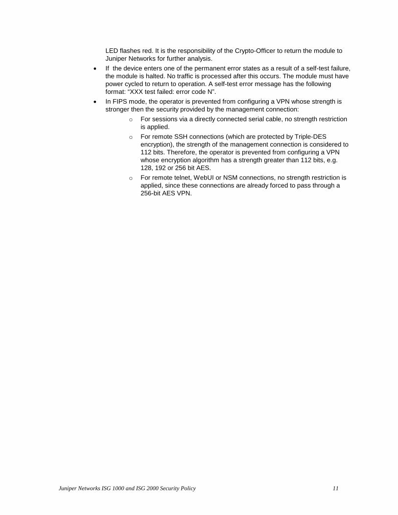
techniques. • The ISG series device is contained within a metal production-grade enclosure.
Fig. 1:Front of the ISG 1000, with location of tamper evident seals
Juniper Networks ISG 1000 and ISG 2000 Security Policy 13
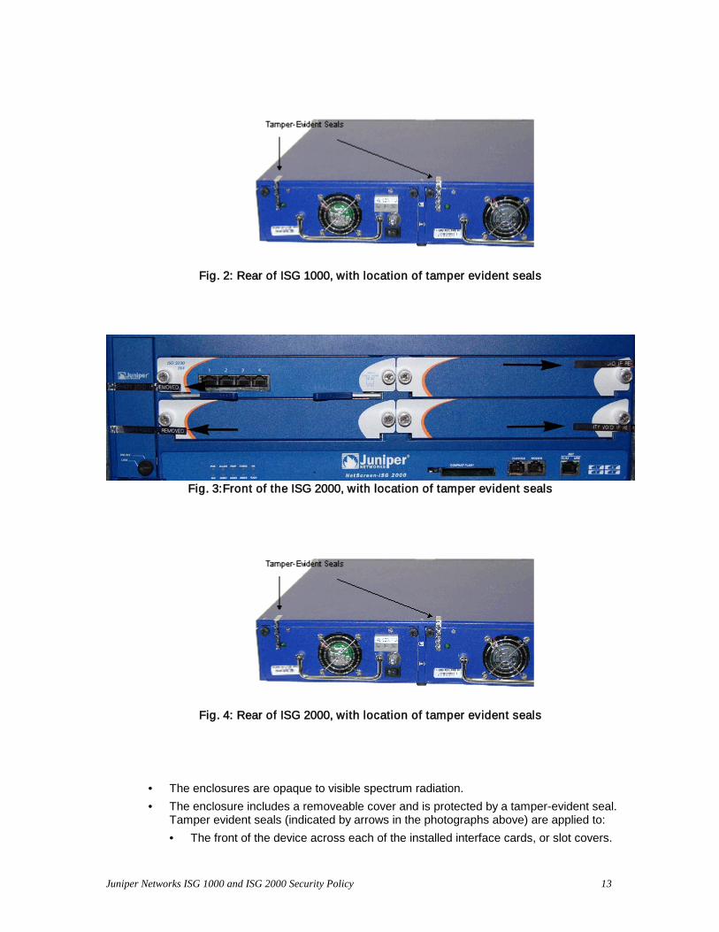
Fig. 2: Rear of ISG 1000, with location of tamper evident seals
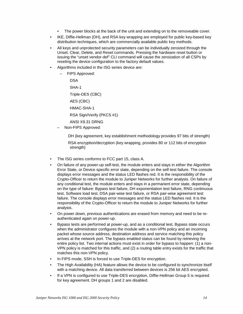
Fig. 3:Front of the ISG 2000, with location of tamper evident seals
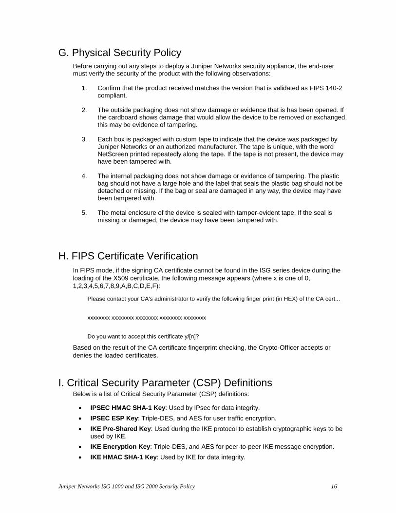
Fig. 4: Rear of ISG 2000, with location of tamper evident seals
• The enclosures are opaque to visible spectrum radiation. • The enclosure includes a removeable cover and is protected by a tamper-evident seal.
Tamper evident seals (indicated by arrows in the photographs above) are applied to: • The front of the device across each of the installed interface cards, or slot covers.
Juniper Networks ISG 1000 and ISG 2000 Security Policy 14
• The power blocks at the back of the unit and extending on to the removeable cover. • IKE, Diffie-Hellman (DH), and RSA key wrapping are employed for public key-based key
distribution techniques, which are commercially available public key methods. • All keys and unprotected security parameters can be individually zeroized through the
Unset, Clear, Delete, and Reset commands. Pressing the hardware reset button or issuing the “unset vendor-def” CLI command will cause the zeroization of all CSPs by reseting the device configuration to the factory default values.
• Algorithms included in the ISG series device are: – FIPS Approved:
DSA
SHA-1
Triple-DES (CBC)
AES (CBC)
HMAC-SHA-1
RSA Sign/Verify (PKCS #1)
ANSI X9.31 DRNG – Non-FIPS Approved:
DH (key agreement, key establishment methodology provides 97 bits of strength)
RSA encryption/decryption (key wrapping, provides 80 or 112 bits of encryption strength)
• The ISG series conforms to FCC part 15, class A. • On failure of any power-up self-test, the module enters and stays in either the Algorithm
Error State, or Device specific error state, depending on the self-test failure. The console displays error messages and the status LED flashes red. It is the responsibility of the Crypto-Officer to return the module to Juniper Networks for further analysis. On failure of any conditional test, the module enters and stays in a permanent error state, depending on the type of failure: Bypass test failure, DH exponentiation test failure, RNG continuous test, Software load test, DSA pair-wise test failure, or RSA pair-wise agreement test failure. The console displays error messages and the status LED flashes red. It is the responsibility of the Crypto-Officer to return the module to Juniper Networks for further analysis.
• On power down, previous authentications are erased from memory and need to be re-authenticated again on power-up.
• Bypass tests are performed at power-up, and as a conditional test. Bypass state occurs when the administrator configures the module with a non-VPN policy and an incoming packet whose source address, destination address and service matching this policy arrives at the network port. The bypass enabled status can be found by retrieving the entire policy list. Two internal actions must exist in order for bypass to happen: (1) a non-VPN policy is matched for this traffic, and (2) a routing table entry exists for the traffic that matches this non-VPN policy.
• In FIPS mode, SSH is forced to use Triple-DES for encryption. • The High Availability (HA) feature allows the device to be configured to synchronize itself
with a matching device. All data transferred between devices is 256 bit AES encrypted. • If a VPN is configured to use Triple-DES encryption, Diffie-Hellman Group 5 is required
for key agreement. DH groups 1 and 2 are disabled.

Juniper Networks ISG 1000 and ISG 2000 Security Policy 15
• The module is not designed to mitigate against attacks which are outside of the scope of FIPS 140-2.
Juniper Networks ISG 1000 and ISG 2000 Security Policy 16
G. Physical Security Policy Before carrying out any steps to deploy a Juniper Networks security appliance, the end-user must verify the security of the product with the following observations:
1. Confirm that the product received matches the version that is validated as FIPS 140-2 compliant.
2. The outside packaging does not show damage or evidence that is has been opened. If the cardboard shows damage that would allow the device to be removed or exchanged, this may be evidence of tampering.
3. Each box is packaged with custom tape to indicate that the device was packaged by Juniper Networks or an authorized manufacturer. The tape is unique, with the word NetScreen printed repeatedly along the tape. If the tape is not present, the device may have been tampered with.
4. The internal packaging does not show damage or evidence of tampering. The plastic bag should not have a large hole and the label that seals the plastic bag should not be detached or missing. If the bag or seal are damaged in any way, the device may have been tampered with.
5. The metal enclosure of the device is sealed with tamper-evident tape. If the seal is missing or damaged, the device may have been tampered with.
H. FIPS Certificate Verification In FIPS mode, if the signing CA certificate cannot be found in the ISG series device during the loading of the X509 certificate, the following message appears (where x is one of 0, 1,2,3,4,5,6,7,8,9,A,B,C,D,E,F):
Please contact your CA's administrator to verify the following finger print (in HEX) of the CA cert...
xxxxxxxx xxxxxxxx xxxxxxxx xxxxxxxx xxxxxxxx
Do you want to accept this certificate y/[n]?
Based on the result of the CA certificate fingerprint checking, the Crypto-Officer accepts or denies the loaded certificates.
I. Critical Security Parameter (CSP) Definitions
Below is a list of Critical Security Parameter (CSP) definitions:
• IPSEC HMAC SHA-1 Key: Used by IPsec for data integrity. • IPSEC ESP Key: Triple-DES, and AES for user traffic encryption. • IKE Pre-Shared Key: Used during the IKE protocol to establish cryptographic keys to be
used by IKE. • IKE Encryption Key: Triple-DES, and AES for peer-to-peer IKE message encryption. • IKE HMAC SHA-1 Key: Used by IKE for data integrity.
Juniper Networks ISG 1000 and ISG 2000 Security Policy 17
• Password: Crypto-Officer and User passwords. • SSH Server/Host DSA Private Key: Used to create digital signatures. • SSH Encryption Key: Triple-DES encryption key to encrypt telnet commands. • SSH HMAC SHA-1 Key: Used by SSH for data integrity. • HA Key: AES Encryption key for HA data. • IKE RSA/DSA Private Key: DSA/RSA key used in IKE identity authentication. • Diffie Hellman Private Key Components: Used during the DH key agreement protocol. • PRNG Algorithm Key: Used during the ANSI X9.31 generation of pseudo random
numbers.
Juniper Networks ISG 1000 and ISG 2000 Security Policy 18
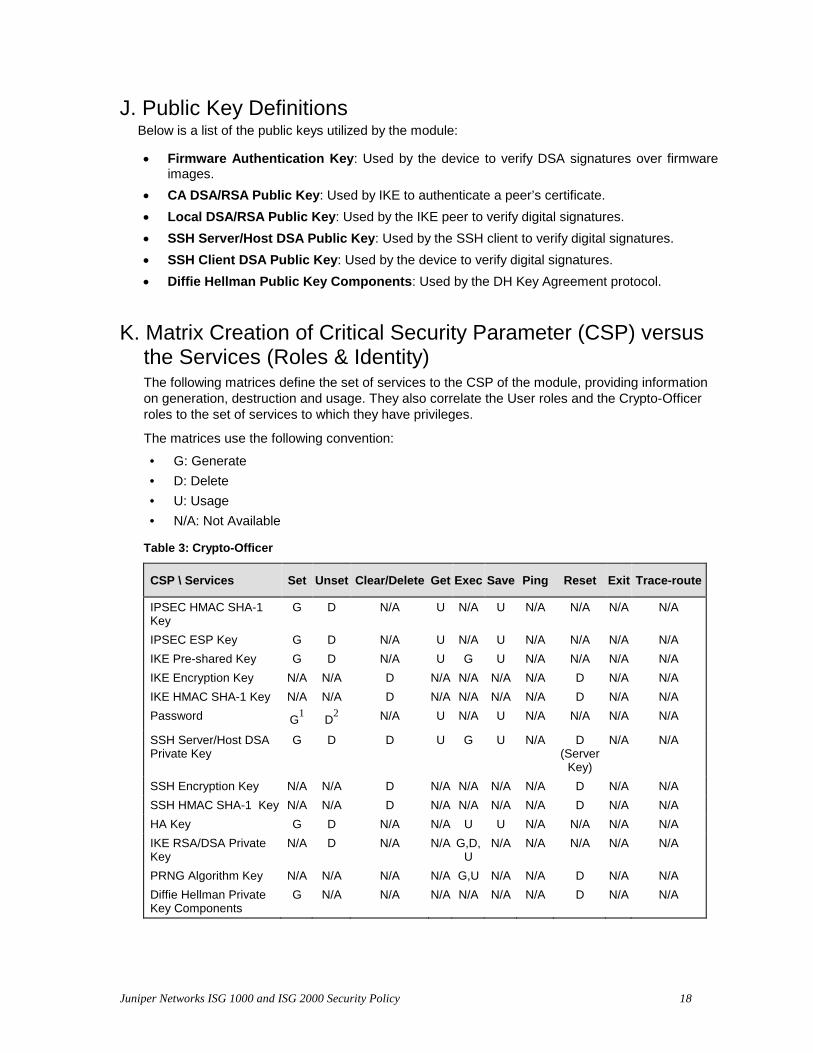
J. Public Key Definitions Below is a list of the public keys utilized by the module:
• Firmware Authentication Key: Used by the device to verify DSA signatures over firmware images.
• CA DSA/RSA Public Key: Used by IKE to authenticate a peer’s certificate. • Local DSA/RSA Public Key: Used by the IKE peer to verify digital signatures. • SSH Server/Host DSA Public Key: Used by the SSH client to verify digital signatures. • SSH Client DSA Public Key: Used by the device to verify digital signatures. • Diffie Hellman Public Key Components: Used by the DH Key Agreement protocol.
K. Matrix Creation of Critical Security Parameter (CSP) versus the Services (Roles & Identity) The following matrices define the set of services to the CSP of the module, providing information on generation, destruction and usage. They also correlate the User roles and the Crypto-Officer roles to the set of services to which they have privileges.
The matrices use the following convention:
• G: Generate • D: Delete • U: Usage • N/A: Not Available
Table 3: Crypto-Officer
CSP \ Services Set Unset Clear/Delete Get Exec Save Ping Reset Exit Trace-route
IPSEC HMAC SHA-1 Key
G D N/A U N/A U N/A N/A N/A N/A
IPSEC ESP Key G D N/A U N/A U N/A N/A N/A N/A IKE Pre-shared Key G D N/A U G U N/A N/A N/A N/A IKE Encryption Key N/A N/A D N/A N/A N/A N/A D N/A N/A IKE HMAC SHA-1 Key N/A N/A D N/A N/A N/A N/A D N/A N/A Password G1 D2 N/A U N/A U N/A N/A N/A N/A
SSH Server/Host DSA Private Key
G D D U G U N/A D (Server
Key)
N/A N/A
SSH Encryption Key N/A N/A D N/A N/A N/A N/A D N/A N/A SSH HMAC SHA-1 Key N/A N/A D N/A N/A N/A N/A D N/A N/A HA Key G D N/A N/A U U N/A N/A N/A N/A IKE RSA/DSA Private Key
N/A D N/A N/A G,D,U
N/A N/A N/A N/A N/A
PRNG Algorithm Key N/A N/A N/A N/A G,U N/A N/A D N/A N/A Diffie Hellman Private Key Components
G N/A N/A N/A N/A N/A N/A D N/A N/A
Juniper Networks ISG 1000 and ISG 2000 Security Policy 19
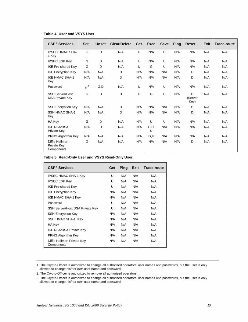
Table 4: User and VSYS User
CSP \ Services Set Unset Clear/Delete Get Exec Save Ping Reset Exit Trace-route
IPSEC HMAC SHA-1 Key
G D N/A U N/A U N/A N/A N/A N/A
IPSEC ESP Key G D N/A U N/A U N/A N/A N/A N/A IKE Pre-shared Key G D N/A U G U N/A N/A N/A N/A IKE Encryption Key N/A N/A D N/A N/A N/A N/A D N/A N/A IKE HMAC SHA-1 Key
N/A N/A D N/A N/A N/A N/A D N/A N/A
Password G3 G,D N/A U N/A U N/A N/A N/A N/A
SSH Server/Host DSA Private Key
G D D U G U N/A D (Server
Key)
N/A N/A
SSH Encryption Key N/A N/A D N/A N/A N/A N/A D N/A N/A SSH HMAC SHA-1 Key
N/A N/A D N/A N/A N/A N/A D N/A N/A
HA Key G D N/A N/A U U N/A N/A N/A N/A IKE RSA/DSA Private Key
N/A D N/A N/A G,D,U
N/A N/A N/A N/A N/A
PRNG Algorithm Key N/A N/A N/A N/A G,U N/A N/A N/A N/A N/A Diffie Hellman Private Key Components
G N/A N/A N/A N/A N/A N/A D N/A N/A
Table 5: Read-Only User and VSYS Read-Only User
CSP \ Services Get Ping Exit Trace-route
IPSEC HMAC SHA-1 Key U N/A N/A N/A IPSEC ESP Key U N/A N/A N/A IKE Pre-shared Key U N/A N/A N/A IKE Encryption Key N/A N/A N/A N/A IKE HMAC SHA-1 Key N/A N/A N/A N/A Password U N/A N/A N/A SSH Server/Host DSA Private Key U N/A N/A N/A SSH Encryption Key N/A N/A N/A N/A SSH HMAC SHA-1 Key N/A N/A N/A N/A HA Key N/A N/A N/A N/A IKE RSA/DSA Private Key N/A N/A N/A N/A PRNG Algorithm Key N/A N/A N/A N/A Diffie Hellman Private Key Components
N/A N/A N/A N/A
1. The Crypto-Officer is authorized to change all authorized operators' user names and passwords, but the user is only
allowed to change his/her own user name and password 2. The Crypto-Officer is authorized to remove all authorized operators. 3. The Crypto-Officer is authorized to change all authorized operators' user names and passwords, but the user is only
allowed to change his/her own user name and password.
Juniper Networks ISG 1000 and ISG 2000 Security Policy 20
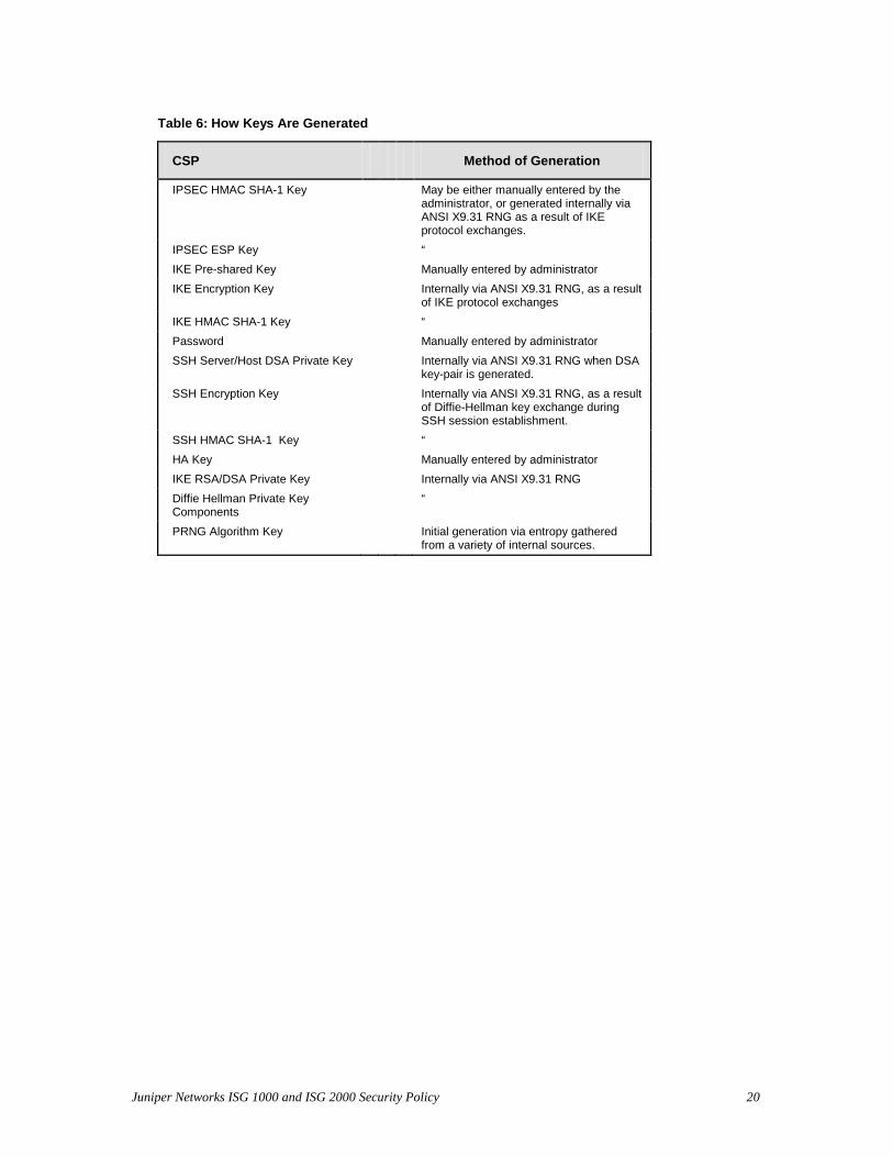
Table 6: How Keys Are Generated
CSP Method of Generation
IPSEC HMAC SHA-1 Key May be either manually entered by the administrator, or generated internally via ANSI X9.31 RNG as a result of IKE protocol exchanges.
IPSEC ESP Key “ IKE Pre-shared Key Manually entered by administrator IKE Encryption Key Internally via ANSI X9.31 RNG, as a result
of IKE protocol exchanges IKE HMAC SHA-1 Key “ Password Manually entered by administrator SSH Server/Host DSA Private Key Internally via ANSI X9.31 RNG when DSA
key-pair is generated. SSH Encryption Key Internally via ANSI X9.31 RNG, as a result
of Diffie-Hellman key exchange during SSH session establishment.
SSH HMAC SHA-1 Key “ HA Key Manually entered by administrator IKE RSA/DSA Private Key Internally via ANSI X9.31 RNG Diffie Hellman Private Key Components
“
PRNG Algorithm Key Initial generation via entropy gathered from a variety of internal sources.
Juniper Networks ISG 1000 and ISG 2000 Security Policy 21
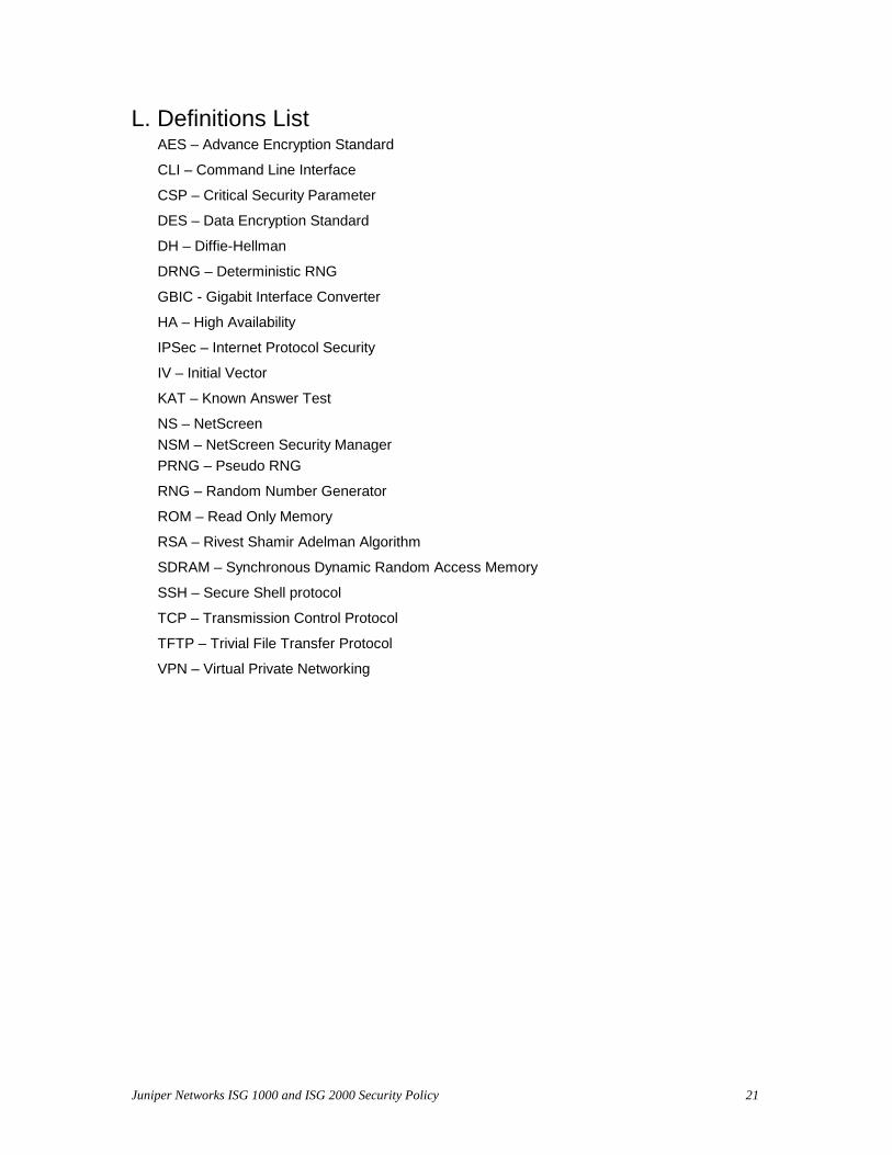
L. Definitions List AES – Advance Encryption Standard
CLI – Command Line Interface
CSP – Critical Security Parameter
DES – Data Encryption Standard
DH – Diffie-Hellman
DRNG – Deterministic RNG
GBIC - Gigabit Interface Converter
HA – High Availability
IPSec – Internet Protocol Security
IV – Initial Vector
KAT – Known Answer Test
NS – NetScreen NSM – NetScreen Security Manager PRNG – Pseudo RNG
RNG – Random Number Generator
ROM – Read Only Memory
RSA – Rivest Shamir Adelman Algorithm
SDRAM – Synchronous Dynamic Random Access Memory
SSH – Secure Shell protocol
TCP – Transmission Control Protocol
TFTP – Trivial File Transfer Protocol
VPN – Virtual Private Networking


![ISG-600 0.37 470 0.49 790 ü]fiEñ (kWh) ISG-400 29 …...ISG-600 0.37 470 0.49 790 ü]fiEñ (kWh) ISG-400 29 ISG-600 49 DAITOËtff± 2020 TEL (022) 253 -7445 TEL (047) 395- 3335 TEL](https://img.pdfslide.us/doc/110x75/5e5d97d3470c0964465f340b/isg-600-037-470-049-790-fie-kwh-isg-400-29-isg-600-037-470-049-790.jpg)