Embed Size (px)
Citation preview

IS300 Series Servo Drive Troubleshooting Instructions
IS300 Series Servo Drive
Troubleshooting Instructions
Shenzhen Inovance Technology Co., Ltd.
All Rights Reserved.

Contents
1
Contents
Preface............................................................................................................2
Chapter 1 Safety Precautions .......................................................................3
Chapter 2 Technical Specifications and Electrical Installation..................6
2.1 IS300 Servo Drive Models and Specifications .................................................6
2.2 Selection of Braking Unit and Braking Resistor ..............................................8
2.3 Electrical Wiring ......................................................................................... 11
Chapter 3 Operation, Display and Trial Running ......................................13
3.1 Operation and Display ................................................................................13
3.2 Viewing and Modifying Function Codes .......................................................15
3.3 Flowchart of Commissioning the Servo Hydraulic Pump...............................16
3.4 Motor Trial Running....................................................................................16
3.5 Servo Pump Commissioning.......................................................................19
Chapter 4 Function Code Table ..................................................................20
Chapter 5 Troubleshooting .........................................................................26
5.1 Troubleshooting of Common Faults with Alarm ............................................26
5.2 Troubleshooting of Common Faults without Alarm .......................................36

Preface
2
Preface
Based on many applications of Inovance servo drive specialized for the hydraulic pump
system and experts' experience in the industrial control technology, this manual is
complied to help users quickly locate and solve problems.
The manual collects onsite maintenance skills and experience of service personnel of
Inovance and injection molding machine (IMM) manufacturers. It is aimed at helping
users to perform routine maintenance and troubleshooting on Inovance IS300 servo
drive, and quickly locate and rectify basic faults to restore manufacturing.
This manual can also be used as the training material for the service personnel of IMM
manufacturers and help them to find the fault causes timely on site and provide more
professional services.

Chapter 1 Safety Precautions
3
Chapter 1 Safety Precautions
1. Servo motor insulation test
Perform the insulation test when the servo motor is used for the first time, reused after
being stored for a long time, or in a regular checkup, in order to prevent poor insulation of
servo motor windings from damaging the servo drive. The servo motor must be
disconnected from the servo drive during the insulation test. A 500-V mega-Ohm meter is
recommended for the test. Ensure that the insulation resistance is not less than 5 MΩ.
2. Thermal protection of motor
If the rated capacity of the motor selected does not match that of the servo drive,
especially when the rated power of the servo drive is greater than that of the motor, adjust
the motor protection parameters on the operation panel of the servo drive or install a
thermal relay for the motor for protection.
3. Motor heat and noise
The output of the servo drive is pulse width modulation (PWM) wave with certain
harmonics, and therefore, the temperature rise, noise, and vibration are slightly greater
than those at running with the mains frequency.
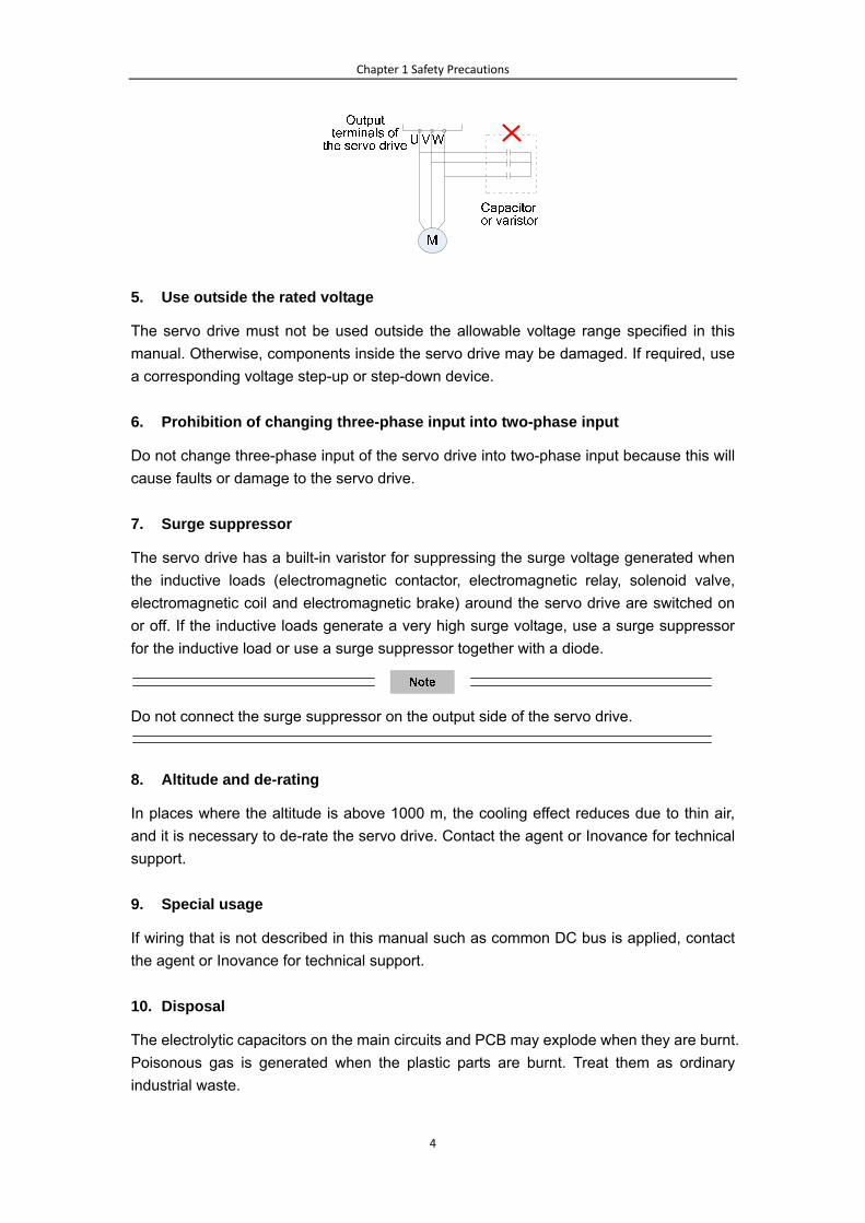
4. Voltage-sensitive device or capacitor on the output side of the servo drive
The output of the AC drive is PWM wave. Do not install the capacitor for improving power
factor or lightning protection voltage-sensitive resistor on the output side of AC drive.
Otherwise, the AC drive may suffer transient overcurrent or even be damaged.
Chapter 1 Safety Precautions
4
5. Use outside the rated voltage
The servo drive must not be used outside the allowable voltage range specified in this
manual. Otherwise, components inside the servo drive may be damaged. If required, use
a corresponding voltage step-up or step-down device.
6. Prohibition of changing three-phase input into two-phase input
Do not change three-phase input of the servo drive into two-phase input because this will
cause faults or damage to the servo drive.
7. Surge suppressor
The servo drive has a built-in varistor for suppressing the surge voltage generated when
the inductive loads (electromagnetic contactor, electromagnetic relay, solenoid valve,
electromagnetic coil and electromagnetic brake) around the servo drive are switched on
or off. If the inductive loads generate a very high surge voltage, use a surge suppressor
for the inductive load or use a surge suppressor together with a diode.
Do not connect the surge suppressor on the output side of the servo drive.
8. Altitude and de-rating
In places where the altitude is above 1000 m, the cooling effect reduces due to thin air,
and it is necessary to de-rate the servo drive. Contact the agent or Inovance for technical
support.
9. Special usage
If wiring that is not described in this manual such as common DC bus is applied, contact
the agent or Inovance for technical support.
10. Disposal
The electrolytic capacitors on the main circuits and PCB may explode when they are burnt.
Poisonous gas is generated when the plastic parts are burnt. Treat them as ordinary
industrial waste.

Chapter 1 Safety Precautions
5
11. Adaptable motor
The standard adaptable motor is permanent synchronous servo motor.
The standard parameters of the adaptable motor have been configured inside the servo
drive. It is still necessary to perform motor auto-tuning or modify the default values based
on actual conditions. Otherwise, the running effect and protection performance will be
affected.
The servo drive may alarm or even be damaged when short-circuit exists on cables or
inside the motor. Therefore, perform the insulation short-circuit test when the motor and
cables are newly installed or during routine maintenance. During the test, make sure that
the servo drive is completely disconnected from the testing parts.

Chapter 2 Technical Specifications and Electrical Installation
6
Chapter 2 Technical Specifications and Electrical Installation
2.1 IS300 Servo Drive Models and Specifications
Motor Power (S1)
Servo Drive Model
Power
Capacity
(kVA)
Input
Current
(A)
Output
Current
(A) kW HP
Single-phase 220–230 V, 50/60 Hz
IS300S002-C 1 5.4 2.3 0.4 0.5
IS300S003-C 1.5 8.2 4 0.75 1
IS300S004-C 3 14 7 1.5 2
IS300S005-C 4 23 9.6 2.2 3
Three-phase 220 V, 50/60 Hz
IS300-2T002-C 1.5 3.4 2.1 0.4 0.5
IS300-2T003-C 3 5 3.8 0.75 1
IS300-2T004-C 4 5.8 5.1 1.5 2
IS300-2T005-C 5.9 10.5 9 2.2 3
IS300-2T010-C 8.9 14.6 13 3.7 5
IS300-2T020-C 17 26 25 5.5 7.5
IS300-2T030-C 21 35 32 7.5 10
IS300-2T040-C 30 46.5 45 11 15
IS300-2T050-C 40 62 60 15 20
IS300-2T070-C 57 76 75 18.5 25
IS300-2T080-C 69 92 91 22 30
IS300-2T100-C 85 113 112 30 40
IS300-2T140-C 114 157 150 37 50
IS300-2T170-C 134 180 176 45 60
IS300-2T210-C 160 214 210 55 75
IS300-2T300-C 231 307 304 75 100
IS300-2T140-C-L 114 157 150 37 50
IS300-2T170-C-L 134 180 176 45 60
IS300-2T210-C-L 160 214 210 55 75
IS300-2T300-C-L 231 307 304 75 100
Three-phase 380–440 V, 50/60 Hz
IS300T002-C 1.5 3.4 2.1 0.75 1
IS300T003-C 3 5 3.8 1.5 2
IS300T004-C 4 5.8 5.1 2.2 3
IS300T005-C 5.9 10.5 9 3.7 5
IS300T010-C 8.9 14.6 13 5.5 7.5
IS300T015-C 11 20.5 17 7.5 10

Chapter 2 Technical Specifications and Electrical Installation
7
Motor Power (S1)
Servo Drive Model
Power
Capacity
(kVA)
Input
Current
(A)
Output
Current
(A) kW HP
IS300T020-C 17 26 25 11 15
IS300T030-C 21 35 32 15 20
IS300T035-C 24 38.5 37 18.5 25
IS300T040-C 30 46.5 45 22 30
IS300T050-C 40 62 60 30 40
IS300T070-C 57 76 75 37 50
IS300T080-C 69 92 91 45 60
IS300T100-C 85 113 112 55 75
IS300T140-C 114 157 150 75 100
IS300T170-C 134 180 176 90 125
IS300T210-C 160 214 210 110 150
IS300T250-C 192 256 253 132 200
IS300T300-C 231 307 304 160 250
IS300T370-C 250 385 377 200 300
IS300T420-C 280 430 426 220 300
IS300T460-C 355 468 465 250 400
IS300T520-C 396 525 520 280 370
IS300T580-C 445 590 585 315 500
IS300T650-C 500 665 650 355 420
IS300T720-C 565 785 725 400 530
IS300T140-C-L 114 157 150 75 100
IS300T170-C-L 134 180 176 90 125
IS300T210-C-L 160 214 210 110 150
IS300T250-C-L 192 256 253 132 200
IS300T300-C-L 231 307 304 160 250
Three-phase 480 V, 50/60 Hz
IS300-5T002-C 1.5 3.4 2.1 0.75 1
IS300-5T003-C 3 5 3.8 1.5 2
IS300-5T004-C 4 5.8 5.1 2.2 3
IS300-5T005-C 5.9 10.5 9 3.7 5
IS300-5T010-C 8.9 14.6 13 5.5 7.5
IS300-5T015-C 11 20.5 17 7.5 10
IS300-5T020-C 17 26 25 11 15
IS300-5T030-C 21 35 32 15 20
IS300-5T035-C 24 38.5 37 18.5 25
IS300-5T040-C 30 46.5 45 22 30
IS300-5T050-C 40 62 60 30 40
IS300-5T070-C 57 76 75 37 50
IS300-5T080-C 69 92 91 45 60
IS300-5T100-C 85 113 112 55 70

Chapter 2 Technical Specifications and Electrical Installation
8
Motor Power (S1)
Servo Drive Model
Power
Capacity
(kVA)
Input
Current
(A)
Output
Current
(A) kW HP
IS300-5T140-C 114 157 150 75 100
IS300-5T170-C 134 180 176 90 125
IS300-5T210-C 160 214 210 110 150
IS300-5T250-C 192 256 253 132 175
IS300-5T300-C 231 307 304 160 210
IS300-5T370-C 250 385 377 200 260
IS300-5T420-C 280 430 426 220 300
IS300-5T460-C 355 468 465 250 350
IS300-5T520-C 396 525 520 280 370
IS300-5T580-C 445 590 585 315 420
IS300-5T650-C 500 665 650 355 470
IS300-5T720-C 565 785 725 400 530
IS300-5T140-C-L 114 157 150 75 100
IS300-5T170-C-L 134 180 176 90 125
IS300-5T210-C-L 160 214 210 110 150
IS300-5T250-C-L 192 256 253 132 175
IS300-5T300-C-L 231 307 304 160 210
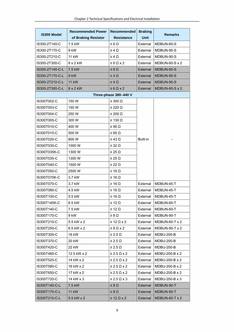
2.2 Selection of Braking Unit and Braking Resistor
IS300 Model Recommended Power
of Braking Resistor
Recommended
Resistance
Braking
Unit Remarks
Single-phase 220–230 V
IS300S002-C 80 W ≥ 200 Ω
IS300S003-C 80 W ≥ 150 Ω
IS300S004-C 100 W ≥ 100 Ω
IS300S005-C 100 W ≥ 70 Ω
Built-in -
Three-phase 220 V
IS300-2T002-C 150 W ≥ 150 Ω
IS300-2T003-C 150 W ≥ 110 Ω
IS300-2T004-C 250 W ≥ 100 Ω
IS300-2T005-C 300 W ≥ 65 Ω
IS300-2T010-C 400 W ≥ 45 Ω
IS300-2T020-C 800 W ≥ 22 Ω
IS300-2T030-C 1000 W ≥ 16 Ω
IS300-2T040-C 1500 W ≥ 11 Ω
IS300-2T050-C 2500 W ≥ 8 Ω
Built-in -
IS300-2T070-C 3.7 kW ≥ 8 Ω External MDBUN-45-S
IS300-2T080-C 4.5 kW ≥ 8 Ω External MDBUN-60-S
IS300-2T100-C 5.5 kW ≥ 6 Ω External MDBUN-60-S
Chapter 2 Technical Specifications and Electrical Installation
9
IS300 Model Recommended Power
of Braking Resistor
Recommended
Resistance
Braking
Unit Remarks
IS300-2T140-C 7.5 kW ≥ 6 Ω External MDBUN-60-S
IS300-2T170-C 9 kW ≥ 4 Ω External MDBUN-90-S
IS300-2T210-C 11 kW ≥ 4 Ω External MDBUN-90-S
IS300-2T300-C 8 x 2 kW ≥ 6 Ω x 2 External MDBUN-60-S x 2
IS300-2T140-C-L 7.5 kW ≥ 6 Ω External MDBUN-60-S
IS300-2T170-C-L 9 kW ≥ 4 Ω External MDBUN-90-S
IS300-2T210-C-L 11 kW ≥ 4 Ω External MDBUN-90-S
IS300-2T300-C-L 8 x 2 kW ≥ 6 Ω x 2 External MDBUN-60-S x 2
Three-phase 380–440 V
IS300T002-C 150 W ≥ 300 Ω
IS300T003-C 150 W ≥ 220 Ω
IS300T004-C 250 W ≥ 200 Ω
IS300T005-C 300 W ≥ 130 Ω
IS300T010-C 400 W ≥ 90 Ω
IS300T015-C 500 W ≥ 65 Ω
IS300T020-C 800 W ≥ 43 Ω
IS300T030-C 1000 W ≥ 32 Ω
IS300T035K-C 1300 W ≥ 25 Ω
IS300T035-C 1300 W ≥ 25 Ω
IS300T040-C 1500 W ≥ 22 Ω
IS300T050-C 2500 W ≥ 16 Ω
IS300T070K-C 3.7 kW ≥ 16 Ω
Built-in -
IS300T070-C 3.7 kW ≥ 16 Ω External MDBUN-45-T
IS300T080-C 4.5 kW ≥ 16 Ω External MDBUN-45-T
IS300T100-C 5.5 kW ≥ 16 Ω External MDBUN-45-T
IS300T140K-C 6.5 kW ≥ 12 Ω External MDBUN-60-T
IS300T140-C 7.5 kW ≥ 12 Ω External MDBUN-60-T
IS300T170-C 9 kW ≥ 8 Ω External MDBUN-90-T
IS300T210-C 5.5 kW x 2 ≥ 12 Ω x 2 External MDBUN-60-T x 2
IS300T250-C 6.5 kW x 2 ≥ 8 Ω x 2 External MDBUN-90-T x 2
IS300T300-C 16 kW ≥ 2.5 Ω External MDBU-200-B
IS300T370-C 20 kW ≥ 2.5 Ω External MDBU-200-B
IS300T420-C 22 kW ≥ 2.5 Ω External MDBU-200-B
IS300T460-C 12.5 kW x 2 ≥ 2.5 Ω x 2 External MDBU-200-B x 2
IS300T520-C 14 kW x 2 ≥ 2.5 Ω x 2 External MDBU-200-B x 2
IS300T580-C 16 kW x 2 ≥ 2.5 Ω x 2 External MDBU-200-B x 2
IS300T650-C 17 kW x 2 ≥ 2.5 Ω x 2 External MDBU-200-B x 2
IS300T720-C 14 kW x 3 ≥ 2.5 Ω x 3 External MDBU-200-B x 3
IS300T140-C-L 7.5 kW ≥ 8 Ω External MDBUN-90-T
IS300T170-C-L 11 kW ≥ 8 Ω External MDBUN-90-T
IS300T210-C-L 5.5 kW x 2 ≥ 12 Ω x 2 External MDBUN-60-T x 2

Chapter 2 Technical Specifications and Electrical Installation
10
IS300 Model Recommended Power
of Braking Resistor
Recommended
Resistance
Braking
Unit Remarks
IS300T250-C-L 6.5 kW x 2 ≥ 8 Ω x 2 External MDBUN-90-T x 2
IS300T300-C-L 16 kW ≥ 2.5 Ω External MDBU-200-B
Three-phase 480 V
IS300-5T002-C 150 W ≥ 300 Ω
IS300-5T003-C 150 W ≥ 220 Ω
IS300-5T004-C 250 W ≥ 200 Ω
IS300-5T005-C 300 W ≥ 130 Ω
IS300-5T010-C 400 W ≥ 90 Ω
IS300-5T015-C 500 W ≥ 65 Ω
IS300-5T020-C 800 W ≥ 43 Ω
IS300-5T030-C 1000 W ≥ 32 Ω
IS300-5T035-C 1300 W ≥ 25 Ω
IS300-5T040-C 1500 W ≥ 22 Ω
IS300-5T050-C 2500 W ≥ 16 Ω
Built-in -
IS300-5T070-C 3.7 kW ≥ 16 Ω External MDBUN-45-5T
IS300-5T080-C 4.5 kW ≥ 16 Ω External MDBUN-45-5T
IS300-5T100-C 5.5 kW ≥ 16 Ω External MDBUN-45-5T
IS300-5T140-C 7.5 kW ≥ 12 Ω External MDBUN-60-5T
IS300-5T170-C 9 kW ≥ 8 Ω External MDBUN-90-5T
IS300-5T210-C 11 kW ≥ 8 Ω External MDBUN-90-5T
IS300-5T250-C 6.5 kW x 2 ≥ 12 Ω x 2 External MDBUN-60-5T x 2
IS300-5T300-C 16 kW ≥ 2.5 Ω External MDBU-200-D
IS300-5T370-C 20 kW ≥ 2.5 Ω External MDBU-200-D
IS300-5T420-C 22 kW ≥ 2.5 Ω External MDBU-200-D
IS300-5T460-C 12.5 kW x 2 ≥ 2.5 Ω x 2 External MDBU-200-D x 2
IS300-5T520-C 14 kW x 2 ≥ 2.5 Ω x 2 External MDBU-200-D x 2
IS300-5T580-C 16 kW x 2 ≥ 2.5 Ω x 2 External MDBU-200-D x 2
IS300-5T650-C 17 kW x 2 ≥ 2.5 Ω x 2 External MDBU-200-D x 2
IS300-5T720-C 14 kW x 3 ≥ 2.5 Ω x 3 External MDBU-200-D x 3
IS300-5T140-C-L 7.5 kW ≥ 12 Ω External MDBUN-60-5T
IS300-5T170-C-L 9 kW ≥ 8 Ω External MDBUN-90-5T
IS300-5T210-C-L 11 kW ≥ 8 Ω External MDBUN-90-5T
IS300-5T250-C-L 6.5 kW x 2 ≥ 12 Ω x 2 External MDBUN-60-5T x 2
IS300-5T300-C-L 16 kW ≥ 2.5 Ω External MDBU-200-D
1. " x 2" indicates that two braking units with their respective braking resistor are connected in parallel. " x
3" means the same.
2. The models in grey are customized (servo drive of water cooling).

Chapter 2 Technical Specifications and Electrical Installation
11
2.3 Electrical Wiring
The electrical wiring figures below are aiming at helping the users who initially use the
servo drive to be able to perform the operations described in the troubleshooting process.
2.3.1 Wiring of the External Braking Unit
Two wiring methods are provided, differing in the wiring of braking resistor overheat
protection.
Wiring method 1: After the signal of the braking resistor overheat relay is sent, the power
supply of the IS300 is cut off.
Wiring method 2: The signal of the braking resistor overheat relay is used as input of the
IS300 external fault (Err15).
Figure 3-18 Basic wiring method 1
In this wiring method, the input voltage class of the contactor control coil is 220 VAC. The NC contact of
the thermal relay is connected to the power supply of the wire package driven by the main contactor.
When a fault occurs, the driving power supply of the contactor is cut off to disconnect the main contactor.

Chapter 2 Technical Specifications and Electrical Installation
12
Figure 3-19 Basic wiring method 2
2.3.2 Wiring Diagram of System Application
Figure 2-3 Wiring of the IS300 system
Circuit breaker
IS300CN2
CN2
CN3
CN5R
S
TM
+ – PBU
V
W
Encoder
Servo hydraulic pump
CGND485B
CANHCANL
485A
CN12
Built-in PG card
Shield
Shield
PG connecting cable
Model: S3T113CZ-PG
PTCPPTCN
AI1AI2AI3
10V13VGNDAO1AO2
GND
DI1DI2DI3DI4DI5
COM
COM
OP24V
Thermistor
T/A1T/B1T/C1T/A2T/C2T/A3T/C3
Oil pump enabled DO1
DO2
DO3
DO4
DO5
C OM
AO1
AO2
GND
AI1
AI2
GND
PID selection terminal 1Slave pump address selection terminal 1
Fault reset CAN communication enabled (multi-pump convergent flow)
Oil pressure reference: 0-10 V
Flow reference: 0-10 V
Current oil pressure detection: 0-10 V/0-20 mA
Current flow detection: 0-10 V/0-20 mA
C OM
DI1
DI2
COM
DI3
C OMDI4
Fault output (NO/NC)Double-discharge plunger
pump sloping switchover (NO)Pressure control state output (NC)
CN1
CN1
Three-phase power supply L2
L3
L1
PE
MCCB MCContactor Magnetic core
(wind one coil)
L2
L3
L1
PE
S
T
R
Filter
U- U+ Z- Z+ COS-B-
COS+B-
SIN-B-
SIN+B-
EXC-GND
EXC+VCC
J4 J3 J2
RedBlueWhiteBrownYellowGreen
Control cable interface board of the servo motor
+13VAI3
GNDPressure sensor
+13VAI3
GNDPressure sensor
24Vdc
Wiring of internal power supply
Wiring of external power supply
Braking resistor
MDBUNBraking unit
+ – PB
PE
BR P(+)
Braking unitMDBUN
Braking resistor
Braking resistor
P +
PE
BR P(+)
Braking unitMDBUN
Braking resistor
+ – PB –
External reactor
Below 30 kW
37-55 kW Above 55 kW
12345
6789
J3
J3
Computer for the injection molding machine

Chapter 3 Operation, Display and Trial Running
13
Chapter 3 Operation, Display and Trial Running
3.1 Operation and Display
You can modify the parameters, monitor the working status and start or stop the servo
drive by operating the operation panel. The following figure shows the operation panel.
Figure 3-1 Diagram of the operation panel
3.1.1 Description of Function Indicators
RUN
ON indicates that the servo drive is in the running state, and OFF indicates that the
servo drive is in the stop state.
LOCAL/REMOT
It indicates whether the servo drive is operated by means of operation panel, terminal
or communication.
LOCAL/REMOT: OFF Operation panel
control
LOCAL/REMOT: ON Terminal control
LOCAL/REMOT: blinking Communication
control
FWD/REV
ON indicates reverse rotation, and OFF indicates forward rotation.
TUNE/TC
Chapter 3 Operation, Display and Trial Running
14
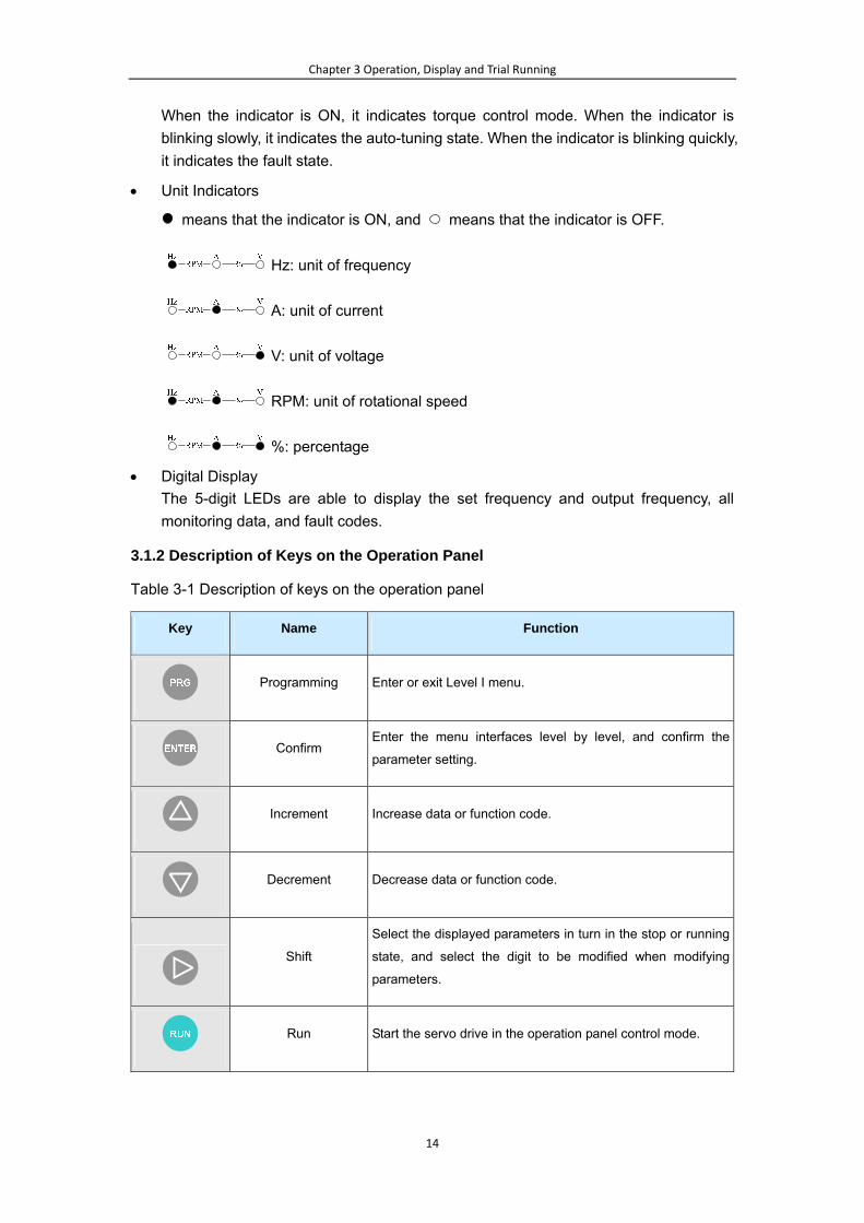
When the indicator is ON, it indicates torque control mode. When the indicator is
blinking slowly, it indicates the auto-tuning state. When the indicator is blinking quickly,
it indicates the fault state.
Unit Indicators
means that the indicator is ON, and means that the indicator is OFF.
Hz: unit of frequency
A: unit of current
V: unit of voltage
RPM: unit of rotational speed
%: percentage
Digital Display
The 5-digit LEDs are able to display the set frequency and output frequency, all
monitoring data, and fault codes.
3.1.2 Description of Keys on the Operation Panel
Table 3-1 Description of keys on the operation panel
Key Name Function
Programming Enter or exit Level I menu.
Confirm
Enter the menu interfaces level by level, and confirm the
parameter setting.
Increment Increase data or function code.
Decrement Decrease data or function code.
Shift
Select the displayed parameters in turn in the stop or running
state, and select the digit to be modified when modifying
parameters.
Run Start the servo drive in the operation panel control mode.

Chapter 3 Operation, Display and Trial Running
15
Stop/Reset
Stop the servo drive when it is in the running state and
perform the reset operation when it is in the fault state.
Quick Enter or exit Level I quick menu.
Reserved Reserved
3.2 Viewing and Modifying Function Codes
The operation panel of the IS300 adopts three-level menu.
The three-level menu consists of function code group (Level I), function code (Level II),
and function code setting value (level III), as shown in the following figure.
Figure 3-2 Operation procedure on the operation panel
You can return to Level II menu from Level III menu by pressing or . The
difference is as follows:
After you press , the system saves the parameter setting first, and then goes
back to Level II menu and shifts to the next function code.
After you press , the system does not save the parameter setting, but directly
returns to Level II menu and remains at the current function code.
Here is an example of changing the value of F3-02 from 10.00 Hz to 15.00 Hz.
Figure 3-3 Example of changing the parameter value
In Level III menu, if the parameter has no blinking digit, it means that the parameter

Chapter 3 Operation, Display and Trial Running
16
cannot be modified. This may be because:
Such a function code is only readable, such as, servo drive model, actually detected
parameter and running record parameter.
Such a function code cannot be modified in the running state and can only be
changed at stop.
3.3 Flowchart of Commissioning the Servo Hydraulic Pump
Figure 3-4 Flowchart of commissioning the servo hydraulic pump
3.4 Motor Trial Running
3.4.1 Motor Trial Running Procedure
Procedure Pr. Setting Value Description
1. Set the control mode. A3-00 = 0 Non-hydraulic
control mode
The servo drive is set to the
non-hydraulic control mode.
2. Set the command
source. F0-02 = 0
Operation panel
control
The LOCAL/REMOT indicator on the
operation panel becomes OFF.
3. Perform motor
auto-tuning.
For details, see section 3.4.3 “Setting and Auto-tuning of Motor
Parameters”.
4. Perform motor trial
running F0-08
Trial running
frequency.
Start trial running in operation panel
control and monitor whether the output
current is normal and whether the
motor runs stably.
3.4.2 Trial Running Check
1) Check whether the running direction of the servo drive is correct. If not, exchange any
two phases of UVW, re-perform motor auto-tuning and then perform motor trial
running.
2) If the motor runs abnormally, check the motor parameters in group F1 and the setting

Chapter 3 Operation, Display and Trial Running
17
of A1-04 (Number of pole pairs of resolver). Then re-perform motor auto-tuning and
perform motor trial running.
3) If the motor oscillates or runs with low frequency noise, weaken the speed loop and
the current loop appropriately. For example, decrease the values of F2-00, F2-03,
F2-13, F2-14, F2-15 and F2-16, and increase the values of F2-01 and F2-04.
4) If the motor rotational speed is not steady, enhance the speed loop and the current
loop appropriately. For example, increase the values of F2-00, F2-03, F2-13, F2-14,
F2-15 and F2-16, and decrease the values of F2-01 and F2-04
The parameters of speed loop and current loop are defined in group F2.
The speed loop and current loop response directly affects pressure stability. Set stronger speed
loop and current loop response if allowed.
3.4.3 Setting and Auto-tuning of Motor Parameters
Parameter Setting
The IS300 controls the servo pump in closed-loop vector control (CLVC) mode. This mode
requires accurate motor parameters. To guarantee good driving performance and running
efficiency, set the motor parameters strictly according to the nameplate of the standard
adaptable motor. The following table lists the parameters to be set.
Function Code Parameter Name Description
F1-00 Motor type
0: Common asynchronous motor
1: Variable-frequency asynchronous motor
2: PMSM
F1-01 to F1-05
Rated motor power
Rated motor voltage
Rated motor current
Rated motor frequency
Rated motor rotational
speed
Model parameters, manual input
A1-04 Number of pole pairs of
resolver -
F1-15 Back EMF
1: Obtain the value directly from the manual
provided by the motor manufacturer.
2: Obtain the value by means of dynamic
auto-tuning if the value cannot be obtained
from the motor manufacturer.
F1-16 Auto-tuning mode Dynamic and static
Motor Auto-tuning Setting

Chapter 3 Operation, Display and Trial Running
18
Auto-tuning
Mode Pr. Setting Application
No operation F1-16 = 0 After motor auto-tuning is completed, the value of F1-16 is
restored to 0 automatically.
Static
auto-tuning 1 F1-16 = 1
This mode is used when the back EMF of the motor is known.
The motor runs at a low speed during auto-tuning, and
therefore, the overflow valve need not be opened.
Dynamic
auto-tuning F1-16 = 2
This mode is used when the back EMF of the motor is
unknown.
The motor runs at a high speed during auto-tuning, and
therefore, the overflow valve must be opened. With-load
auto-tuning reduces the accuracy of motor auto-tuning,
affecting the system control performance.
Static
auto-tuning 2 F1-16 = 3
This mode is used when the back EMF of the motor is known
and there is heavy load.
The motor runs at a low speed during auto-tuning, and
therefore, the overflow valve need not be opened.
When wiring of the encoder and motor is correct but Err43 is
reported, use this mode. Otherwise, the resolver feedback
signal is wrong. In this case, check the encoder signal wiring
and installation accuracy.
Motor Auto-tuning Procedure
Figure 4-11 Motor auto-tuning procedure

Chapter 3 Operation, Display and Trial Running
19
3.5 Servo Pump Commissioning
3.5.1 AI Zero Drift Auto Correction
Step Function
Code Setting
Parameter
Description Remarks
1. Set the
command source. F0-02 = 0
The operation panel
control mode is used.
The LOCAL/REMOT indicator is
OFF.
2. Perform AI zero
drift auto correction. A3-20 = 1
The AI zero drift auto
correction function is
enabled.
After the operation panel displays
"Alcod", press . Then, AI zero
drift auto correction is carried out.
You can also perform AI zero drift correction manually: When A3-20= 0 (that is, AI zero drift auto
correction is disabled), view the values of three AIs in U1-04 to U1-06, add 10 mA to each of the
values and then enter the results in F4-18, F4-23, and F4-28.
After AI zero drift auto correction is completed, the value of A3-20 is automatically restored to 0.
3.5.2 Selection and Parameter Setting of Hydraulic Control Mode
Hydraulic Mode Selection Function Code
Setting Description
Non-hydraulic control mode A3-00 = 0 The speed mode is used.
Hydraulic control mode 1 A3-00 = 1
The host computer provides the hydraulic
pressure reference and flow reference by
using CAN communication; AI3 provides the
hydraulic pressure feedback; the servo drive
conducts hydraulic control.
Hydraulic control mode 2 A3-00 = 2
AI1 provides the hydraulic pressure reference;
AI2 provides flow reference; AI3 provides the
hydraulic pressure feedback; the servo drive
conducts hydraulic control.
CAN hydraulic control mode
(specialized) A3-00 = 3
It is the hydraulic control mode implemented
by using CAN communication with the host
computer. The servo pump control parameters
in group A3 are invalid.
Reserved A3-00 = 4 Reserved

Chapter 4 Function Code Table
20
Chapter 4 Function Code Table
Function
Code Parameter Name Setting Range Min. Unit Default Property
Group U0: Servo Drive Viewing Parameters
U0-00 Running frequency 0.00 Hz to maximum
frequency (F0-10) - -
Group U1: Servo Pump Viewing Parameters
U1-00 Real-time angle 0.0°–359.9° - -
U1-01 Hydraulic pressure
reference
0.0 kg to A3-02 (System
hydraulic) - -
U1-02 Feedback hydraulic
pressure
0.0 kg to A3-03 (Max.
hydraulic) - -
U1-03 Motor rotational speed -9999 to 30000 RPM - -
U1-04 AI1 voltage -10.00 to 10.000 V - -
U1-05 AI2 voltage -10.00 to 10.000 V - -
U1-06 AI3 voltage -10.00 to 10.000 V - -
U1-11 Resolver signal
interference degree 0–1000 - -
Group A1: PG Card Parameters
A1-00 to
A1-01 Reserved - - -
A1-02 Encoder
installation angle 0.0–359.9° 0.1° 0.0°
A1-03 Inversion of feedback
speed 0–1 1 0
A1-04 Number of pole pairs of
resolver 1–50 1 1
A1-05 Resolver signal fault
detection time
0.000: Detection invalid
0.001–60.000s 0.001s 0.000
Group A2: CAN Communication Parameters
A2-01 Local address 1-255 1 1
A2-03 CAN multi-pump mode 0: Broadcast mode
1: Multi-master mode 1 0
Group A3: Servo Pump Control Parameters
A3-00 Hydraulic control mode
0: Non-hydraulic control
mode
1: Servo drive hydraulic
0 0

Chapter 4 Function Code Table
21
Function
Code Parameter Name Setting Range Min. Unit Default Property
control mode 1 (via CAN
communication)
2: Servo drive hydraulic
control mode 2 (via AI)
3:CAN hydraulic mode
(reserved)
4: Reserved
A3-01 Maximum rotational
speed
Rotational speed
corresponding to lower
limit of max. frequency to
30000 RPM
1 RPM 2000 RPM
A3-02 System hydraulic
pressure
0.0 kg/cm2 to A3-03
(Max. hydraulic)
0.0
kg/cm2 175.0 kg/cm2
A3-03 Maximum hydraulic
pressure
System hydraulic (A3-02)
to 500.0 kg/cm2
0.0
kg/cm2 250.0 kg/cm2
A3-04 Hydraulic pressure
command rise time 0–2000 ms 1 ms 20 ms
A3-05 Hydraulic pressure
control Kp1 0.0–800.0 0.1 210.0
A3-06 Hydraulic pressure
control Ti1 0.001–10.000s 0.001s 0.100s
A3-07 Hydraulic pressure
control Td1 0.000–1.000s 0.001s 0.000s
A3-08 Maximum reverse
rotational speed 0.0%–100.0% 0.1% 20.0%
A3-09 Minimum flow 0.0%–50.0% 0.1% 0.5%
A3-10 Minimum pressure 0.0–50.0 kg/cm2 0.1
kg/cm2 0.5 kg/cm2
A3-11 Hydraulic pressure
control Kp2 0.0–800.0 0.1 210.0
A3-12 Hydraulic pressure
control Ti2 0.001–10.000s 0.001s 0.100s
A3-13 Hydraulic pressure
control Td2 0.000–1.000s 0.001s 0.000s
A3-14 Hydraulic pressure
control Kp3 0.0–800.0 0.1 210.0
A3-15 Hydraulic pressure
control Ti3 0.001–10.000s 0.001s 0.100s
A3-16 Hydraulic pressure
control Td3 0.000–1.000s 0.001s 0.000s
A3-17 Hydraulic pressure
control Kp4 0.0–800.0 0.1 210.0

Chapter 4 Function Code Table
22
Function
Code Parameter Name Setting Range Min. Unit Default Property
A3-18 Hydraulic pressure
control Ti4 0.001–10.000s 0.001s 0.100s
A3-19 Hydraulic pressure
control Td4 0.000–1.000s 0.001s 0.000s
A3-20 AI zero drift auto
correction
0: Disabled
1: Enabled 0 0
A3-21
Fault detection time of
hydraulic pressure
sensor
0.000s: Detection invalid
0.001–60.000s 0.001s 0.500s
Group F1: Motor Parameters
F1-00 Motor type selection
0: Common
asynchronous motor
1: Variable frequency
asynchronous motor
2: Permanent
synchronous servo motor
1 2
F1-01 Rated motor power 0.4–1000.0 kW 0.1 kW Model
dependent
F1-02 Rated motor voltage 0–440 V 1 V Model
dependent
F1-03 Rated motor current 0.01–655.35 A 0.01 A Model
dependent
F1-04 Rated motor frequency 0.00 to max. frequency 0.01 Hz Model
dependent
F1-05 Rated motor rotational
speed 0–30000 rpm 1 rpm
Model
dependent
F1-15 Back EMF 0–65535 V 1 Model
dependent
F1-16 Auto-tuning mode
0: No operation
1: Static auto-tuning (low
speed)
2: Dynamic auto-tuning
(high-speed)
3: Static auto-tuning 2
(low speed)
1 0
Group F2: Vector Control Parameters
F2-00 Speed loop proportional
gain 1 0–100 1 60
F2-01 Speed loop integration
time 1 0.01–10.00s 0.01s 0.30s
F2-02 Switchover frequency 1 0.00–F2-05 0.01 Hz 5.00Hz
F2-03 Speed loop proportional 0–100 1 60

Chapter 4 Function Code Table
23
Function
Code Parameter Name Setting Range Min. Unit Default Property
gain 2
F2-04 Speed loop
integration time 2 0.01–10.00s 0.01s 0.30s
F2-05 Switchover frequency 2 F2-02 to max. frequency 0.01 Hz 10.00 Hz
F2-06 Slip compensation
coefficient 50%–200% 1% 100%
F2-07 Time constant of speed
loop filter 0.000–0.100s 0.001s 0.000s
F2-08 Torque control 0: Invalid
1: Valid 1 0
F2-09 Torque upper limit
source
0: F2-10
1: AI1
2: AI2
3: AI3
4: Reserved
5: Via communication
Analog input corresponds
to F2-10.
1 0
F2-10 Torque upper limit 0.0%–250.0% 0.1% 200.0%
F2-11 Encoder PPR 1–65535 1 1024
F2-12 Reserved - - -
F2-13 Shaft D current loop Kp 0–65535 1 50
F2-14 Shaft D current loop Ki 0–65535 1 50
F2-15 Shaft Q current loop Kp 0–65535 1 50
F2-16 Shaft Q current loop Ki 0–65535 1 50
Group F9: Fault and Protection Parameters
F9-00 Motor overload
protection selection
0: Disabled
1: Enabled 1 1
F9-01 Motor overload
protection gain
0.20–10.00 0.01 1.00
F9-04 Braking voltage
threshold
120%–150% (100%
corresponding to 530 V) 1% 130%
F9-12 Input phase loss
protection
0: Disabled
1: Enabled 1 1
F9-13 Output phase loss
protection
0: Disabled
1: Enabled 1 1
F9-14 Runaway speed
deviation 0.50–50.00 Hz 0.01 Hz 10.00 Hz
F9-15 Detection time of
runaway fault
0.0s: No detection
0.1s–20.0s 0.1 10.0s
F9-16 Motor temperature 0: Disabled 1 0

Chapter 4 Function Code Table
24
Function
Code Parameter Name Setting Range Min. Unit Default Property
protection 1: Enabled
F9-17 Reserved - 1 0
F9-18 1st fault type 1 0
F9-19 2nd fault type 1 0
F9-20 Latest fault type
0: No fault
1: Reserved
2: Overcurrent during
acceleration (Err02)
3: Overcurrent during
deceleration (Err03)
4: Overcurrent at
constant speed (Err04)
5: Overvoltage during
acceleration (Err05)
6: Overvoltage during
deceleration (Err06)
7: Overvoltage at
constant speed (Err07)
8: Reserved
9: Under-voltage (Err09)
10: Servo drive overload
(Err10)
11: Motor overload
(Err11)
12: Phase loss on input
side (Err12)
13: Phase loss on output
side (Err13)
14: Module overheat
(Err14)
15: External device fault
(Err15)
16: Communication fault
(Err16)
17: Contactor fault
(Err17)
18: Current detection
fault (Err18)
19: Motor auto-tuning
fault (Err19)
20: Reserved
21: Data overflow (Err21)
22: Reserved
23: Short circuit to ground
1 0

Chapter 4 Function Code Table
25
Function
Code Parameter Name Setting Range Min. Unit Default Property
(Err23)
24-25: Reserved
26: Running time reached
27: Business running
time reached
28-41: Reserved
42: CAN communication
interrupted (Err42)
43: Encoder fault during
motor auto-tuning (Err43)
44: Speed deviation too
large (Err44)
45: Motor overheat
(Err45)
46: Pressure sensor fault
(Err46)
47-48: Multi-pump
parallel run fault (Err47,
Err48)
49: Encoder signal fault
(Err49)
52: Multi-master fault in
multi-pump convergent
flow( Err52)
58: Parameter restoration
fault (Err58)
F9-21 Frequency upon fault - 0.01 Hz -
F9-22 Current upon fault - 0.1 A -
F9-23 Bus voltage upon fault - 0.1 V -
F9-24 Input terminal state
upon fault - 1 -
F9-25 Output terminal state
upon fault - 1 -
Group FP: User Password and Parameter Initialization
FP-00 User password 0–65535 1 0
FP-01 Restore default settings
0–2
0: No operation
1: Restore default
settings
2: Clear fault records
1 0
FP-02 Motor model code 0–65535 1 Model
dependent

Chapter 5 Troubleshooting
26
Chapter 5 Troubleshooting
The mixture of the hydraulic circuit of the IMM and the electrical system is very
complicated. Providing the only digital operation panel, the servo drive may reflect faults
of all peripheral devices. These faults may seem to be caused by the servo drive, but may
be actually caused by other reasons. The following part classifies faults into several types,
and describes the fault principles and corresponding solutions from the most common
ones to less common ones. When a fault occurs, you can first determine the fault type,
analyze the causes, and perform troubleshooting according to the instructions.
5.1 Troubleshooting of Common Faults with Alarm
Fault Code ERR02, ERR03, ERR04
Fault Principle Overcurrent during running
After the fault occurs, view the value of F9-22. If the value is 2.5 times of the rated current, it indicates
that overcurrent occurs on the servo drive.
Fault Cause Solution
Motor commissioning
fault Refer to section 3.4.3 “Setting and Auto-tuning of Motor Parameters”.
Motor short-circuit to
ground
Disconnect the cables from the motor, and measure the to-ground (housing
of the motor) resistance of U, V, W phases by using the M mode in the ohm
function of the multimeter. On normal conditions, the motor to-ground
resistance is above 5 MΩ. If the measured value is smaller than the value, it
indicates that the motor is short-circuited to ground. In this case, you need
to replace the motor.
U V W
Megger
Input terminals of the motor
Ground
Voltage unstable
Check whether the mains voltage drops greatly. If the voltage is lower than
85% of the rated voltage, overcurrent is likely to occur during running. When
the voltage is too low, stop the servo drive immediately and find the causes.
Servo drive not
grounded well
Check whether the grounding cable exists and whether he servo drive is
well grounded. If the servo drive is poorly grounded, adopt the wiring mode
below.

Chapter 5 Troubleshooting
27
Fault Code ERR05, ERR06, ERR07
Fault Principle Overvoltage during running
After the fault occurs, view the value of F9-23. If the value exceeds the software overvoltage
protection value, it indicates that overvoltage occurs on the servo drive. The software overvoltage
protection value is 400 V for 2T, 790 V for T, and 890 V for 5T.
Fault Cause Solution
Resistance of braking
resistor too large
Disconnect the braking resistor from the braking unit, and measure the
resistance of the braking resistor by using a multimeter. Compare the
measured value with the recommended value in section 2.2 “Selection of
Braking Unit and Braking Resistor”. If there is a large difference between the
two values, replace the braking resistor. If the resistance of the braking
resistor is normal, check whether the braking unit is faulty.
Braking unit faulty
Disconnect cables between the +, - terminals of the braking unit and the
servo drive, and measure the braking unit by using the diode function of the
multimeter with the red probe connected to - and black probe connected to
+. If a voltage drop of about 0.3 V is displayed, it indicates that the braking
unit is normal; otherwise, the braking unit is damaged.
Note: When you connect the +, - terminals of the braking unit to the servo
drive again, ensure correct wiring; if the wiring sequence is reversed, the
servo drive will be damaged. Three-phase AC power
Safety contactor
R S T U V W
Servo motor
PE BR P(+)
Braking unit
Braking resistor
Main circuit terminals of IS300
Voltage too high
Check whether the mains voltage changes greatly. If the mains voltage is
20% higher than the rated voltage, overvoltage is likely to occur during
running. When overvoltage occurs, stop the servo drive immediately and
find the causes.
Fault Code ERR09
Fault Principle Mains voltage too low
Fault Cause Solution
Mains voltage lower
than 85% of the rated
voltage
Measure the actual mains voltage by using a multimeter. If the measured
voltage is lower than 85% of the rated voltage, start the servo drive only
after the voltage restores to normal. If the mains voltage is not too low but
this alarm still exists, check whether the voltage fluctuates greatly. In this
case, load change may cause even larger voltage fluctuation and drop.

Chapter 5 Troubleshooting
28
It is normal that the servo drive reports ERR09 at every power-off. It is
considered as a fault only when ERR09 is reported at power-on.
Snubber circuit board
Disconnect the snubber circuit board from the bus and measure its
resistance. If the measured resistance is larger than 36 Ω, it indicates that
the snubber circuit board is faulty.
Main circuit contactor
faulty
The main circuit contactor may be in poor contact or may not work. If the
output current of the servo drive is above 070, check the resistance value
when the contactor closes. If the output current of the servo drive is below
070, contact the IMM manufacturer.
Fault Code ERR10
Fault Principle Servo drive overload
Perform a pressure holding action with the maximum pressure. View the current during this process
and compare it with 1.5 times of the rated current of the servo drive. If the viewed current is larger
than 1.5 times of the rated current, it indicates that the motor may demagnetize or the encoder
installation angle changes.
Fault Cause Solution
Encoder installation
angle changing
Perform motor auto-tuning twice and check whether the value of A1-02
(encoder installation angle) changes. If the value changes a lot, contact
Inovance.
You can refer to section 3.4.3 “Setting and Auto-tuning of Motor Parameters”
or the following procedure to perform the motor auto-tuning.
1. Check that the setting of F1-00 to F1-05 is correct.
2. Set A3-00 to 0 and F0-02 to 0, and then perform auto-tuning.
3. Set F1-16 to 1 and press to start auto-tuning.
This moment "TUNE" is displayed on the operation panel. After
auto-tuning is complete, "TUNE" disappears.
4. Restore the value of A3-00.
5. Start the servo drive again and check whether the alarm persists. If yes,
go to the next step.
Motor encoder fault Refer to the solution of ERR43.
Motor
demagnetization
Turn on the overflow valve and perform dynamic auto-tuning (same as the
operation for the auto-tuning problem but set F1-16 to 2), and view the back
EMF in F1-15. If the value is lower than 270 V, it indicates that motor
demagnetization occurs. In this case, you need to replace the motor.
Problem of the
pressure sensor
Perform an action with pressure 10 kgf, and check the feedback pressure in
U1-02. If the value of U1-02 remains 0, check wiring of the pressure sensor,
or use a new pressure sensor and connect it correctly. Perform the same
action again. If the value of U1-02 is still 0, measure AI3-GND by using a
multimeter; if the measured value is 0, replace the terminal block of the
servo drive.
Heavy load of the
IMM
If the motor is not demagnetized and the alarm is reported with a long time
interval or periodically, it can be determined that the load of the IMM is too

Chapter 5 Troubleshooting
29
large. In this case, to protect the IMM, you need to reduce the load and
properly increase the cooling time.
Motor or hydraulic
pump stuck
Perform any action on the IMM computer to check whether the motor and
hydraulic pump rotate normally. If they do not rotate, it indicates that they get
stuck. In this case, contact the IMM manufacturer.
Fault Code ERR11
Fault Principle Motor overload
Fault Cause Solution
Motor overload
View the rated motor current.
View the value of F1-03 and make it consistent with the rated motor current
on the motor nameplate. If the fault persists, contact the IMM manufacturer.
The motor parameters are F1-01 to F1-05 and F1-15, as listed in the
function code table.
Fault Code ERR12
Fault Principle Phase loss on the input side
Fault Cause Solution
Phase loss on the
input side
1. Peripheral device problem: Check whether the three phases of input
voltage are balanced. If not, eliminate the problem.
Note: When the mains capacity is small and the servo drive is powered on
or off frequently, mains fluctuation is large, causing unbalance of the input
three phases.
Rectifier bridge
problem
Power off the servo drive, and measure the rectifier bridge using the diode
function of the multimeter.
Connect the red probe to the - terminal, and measure R, S, T in turn by
using the black probe. Then, connect the black probe to the + terminal, and
measure R, S, T in turn by using the red probe. If the six measurement
values are all about 0.3 V, it indicates that the rectifier bridge is normal. If the
rectifier bridge is open-circuited, replace the rectifier bridge, power on the
servo drive, and perform trial running again.
Drive board problem If the fault persists after you perform the preceding operations, contact the
IMM manufacturer.

Chapter 5 Troubleshooting
30
Fault Code ERR13
Fault Principle Phase loss on the output side
Fault Cause Solution
Motor fault
Check whether the cables between the servo drive and the motor are
short-circuited or in poor contact.
Disconnect the servo drive from the motor, measure the inter-phase
resistance of U, V, W phases of the motor by using the M mode in the ohm
function of the motor, and check whether the resistance is the same and
above 5 MΩ. If yes, connect the servo drive and the motor and perform trial
running again.
U V W
Megger
Input terminals of the motor
Ground
Module fault
Power off the servo drive, and measure the IGBT by using the diode
function of the multimeter. Connect the red probe to the - terminal, and
measure R, S, T in turn by using the black probe. Then, connect the black
probe to the + terminal, and measure R, S, T in turn by using the red probe.
If the six measurement values are all about 0.3 V, it indicates that the IGBT
is normal.
Internal component
fault
If the fault persists after you perform the preceding operations, contact the
IMM manufacturer.
Fault Code ERR14
Fault Principle Module overheat
Fault Cause Solution
Cooling fan problem
Check whether the fan is damaged. Measure the power supplied by the
drive board to the fan, and see whether the measured value is 24 V.
Eliminate the related problems and perform trial running again.
Air filter problem Check whether the air filter is blocked. If yes, clean the air filter.
Too high ambient
temperature
If the temperature inside the cabinet exceeds 50C, enhance ventilation and
heat dissipation of the cabinet.

Chapter 5 Troubleshooting
31
Fault Code ERR17
Fault Principle Contact fault
Fault Cause Solution
Relay problem
The AC drive of high power class uses DC contact. Coil is connected to 24 V
DC power. On normal conditions, the resistance value of the coil is
approximately 3–4 Ω. When the main contact closes, the resistance value at
the two ends of the contactor is below 0.1 Ω. Check the resistance value of
the coil and the closing condition of the main contact when performing
maintanance on site.
Drive board problem If the fault persists after you perform the preceding operations, contact the
IMM manufacturer.
Fault Code ERR18
Fault Principle Current detection fault
Fault Cause Solution
Hall problem
Check whether hall wiring becomes loose. If not, replace the hall
component.
Drive board problemIf the fault persists after the hall problem is solved, contact the IMM
manufacturer.
Fault Code ERR23
Fault Principle Output short-circuit
Fault Cause Solution
Drive board
short-circuit to ground
Measure whether U, V, W cables of the servo drive are in contact with the
earthing cable by using the diode function of the multimeter. On normal
conditions, they are disconnected. If short-circuit occurs, contact Inovance

Chapter 5 Troubleshooting
32
for technical support.
Motor short-circuit
Check whether the cables between the servo drive and the motor are
short-circuited or in poor contact.
Disconnect the servo drive from the motor, measure the inter-phase
resistance of U, V, W phases of the motor by using the M mode in the ohm
function of the motor, and check whether the resistance is the same and
above 5 MΩ. If yes, connect the servo drive and the motor and perform trial
running again.
If the fault persists, contact the IMM manufacturer.
Fault Code ERR27
Fault Principle Timed startup according to business agreement
Fault Cause Solution
Timed startup
according to business
agreement
Contact the IMM manufacturer.
Fault Code ERR42, ERR47, ERR48
Fault Principle Communication fault
Fault Cause Solution
ERR42
1. Check whether CAN bus cable breaks.
2. Check whether the baud rate of the servo drive is set properly.
3. Check whether all servo drives are in hydraulic control mode.
ERR47
This fault is reported by the master servo drive on normal conditions and is
displayed as ERR47-*, in which * is a number, and indicates that the servo
drive with local address (A2-01) of * reports the fault. After the fault of the
servo drive * is rectified and reset, this fault will be reset simultaneously.
ERR48
This fault is reported by the master servo drive when multiple servo drives
are set to the same local address. Find the duplicated local addresses and
modify them. Set the local addresses of multiple servo drives in the order of
1, 2, 3 ……N and avoid repetitive setting.

Chapter 5 Troubleshooting
33
Fault Code ERR43
Fault Principle Encoder signal feedback abnormal or unavailable
Fault Cause Solution
Auto-tuning fault
If the fault occurs at the first-time auto-tuning, check whether the setting of
F1-01 to F1-05 is correct. If not, correct the setting, and perform auto-tuning
again. If the fault persists, change the auto-tuning mode by setting F1-16 to
3. If the fault still persists, go to the next step.
Encoder wiring
problem
Check wiring of the encoder. Measure the BD9 connector of the encoder by
using the ohm function of the multimeter. The resistance between pins 1 and
2, pins 3 and 4, and pins 5 and 9 is expected to be about 40 Ω or 63 Ω. If the
measured resistance is normal, check whether the wiring sequence
between the encoder and the motor is correct and whether the wiring is
secure. After ensuring that the encoder wiring is correct, perform
auto-tuning again. If the fault persists, go to the next step.
PG card contact
problem
When the encoder is in good contact and powered on, observe whether the
red indicator on the PG card remains on. If yes, it indicates that the PG card
is in poor contact or damaged. After power-off, re-connect the cable on the
right side of the PG card to ensure good contact. Perform auto-tuning again.
If the fault persists, go to the next step.
Peripheral
interference
View the value of U1-11. If the value is larger than 100, check again whether
the encoder wiring is correct and in good contact. If the value is 1000, the
PG card or encoder may be damaged. In this case, replace the PG card,
and view the value of U1-11 again. If the fault persists after ensuring that the
wiring and PG card are normal, it indicates that the encoder may be
damaged.
Hydraulic pump or
motor stuck
Try to rotate the shaft of the motor or hydraulic pump. If the shaft cannot be
rotated, check whether the motor or hydraulic pump is stuck. Eliminate the
problem, and perform auto-tuning again.
Encoder damage It is rather uncommon that the encoder is damaged. If the fault persists after
you perform all the preceding operations, contact the IMM manufacturer.

Chapter 5 Troubleshooting
34
Fault Code ERR44
Fault Principle Too large deviation between actual speed and reference speed
Fault Cause Solution
Servo drive
parameters set
wrongly
Check whether the setting of F2-10 (Torque upper limit) is smaller than
150%. If yes, set F2-10 to 150%. Check that the motor parameters F1-01 to
F1-05 are correct and whether A3-01 (Max. rotational speed) is lower than
F1-05 (Rated rotational speed).
Encoder installation
angle changing
Perform motor auto-tuning twice and check whether the value of A1-02
(encoder installation angle) changes. If the value changes a lot, contact
Inovance.
You can refer to section 3.4.3 “Setting and Auto-tuning of Motor Parameters”
or the following procedure to perform the motor auto-tuning.
1. Check that the setting of F1-00 to F1-05 is correct.
2. Set A3-00 to 0 and F0-02 to 0, and then perform auto-tuning.
3. Set F1-16 to 1 and press RUN
to start auto-tuning.
This moment "TUNE" is displayed on the operation panel. After
auto-tuning is complete, "TUNE" disappears.
4. Restore the value of A3-00.
5. Start the servo drive again and check whether the alarm persists. If yes,
go to the next step.
Motor bearing
damaged or stuck
Hydraulic pump
damaged or stuck
Disconnect the hydraulic pump from the motor and try to rotate the motor or
hydraulic pump manually. Check whether there is resistance or noise during
rotation. If yes, it indicates that the motor or hydraulic pump is faulty and
needs to be repaired.
Encoder wiring
improper
Check whether the encoder cable is wrongly connected, becomes loose or
is short-circuited. If yes, refer to the related solution in ERR43.
External interference,
encoder damaged
View whether the value of U1-11 (Encoder signal interference degree) is 0.
If the value is a non-zero number, it indicates that the encoder suffers
interference. The larger the number is, the bigger the interference is. If the
value is 1000, it indicates that the encoder suffers very big interference, the
encoder is damaged, the encoder cable breaks or the PG card is damaged.
In this case, contact the IMM manufacturer.
Motor demagnetized
Open the overflow valve and perform static auto-tuning (set F1-16 to 2).
Then view the value of F1-15 (Back EMF). If the value is lower than 270 V, it
indicates that the motor is demagnetized. In this case, replace the motor.

Chapter 5 Troubleshooting
35
Fault Code ERR45
Fault Principle Motor overheat protection enabled
Fault Cause Solution
Motor temperature
too high
Check whether the surface of the servo motor is hot. If yes, it indicates that
the temperature is too high. In this case, check the following items:
Whether the load is very heavy
Whether motor heat dissipation is good
Whether the cooling fan is damaged
Whether the dusts block the air filter
If the load is very heavy, reduce the load and then check whether the
temperature declines. If the production requirement cannot be satisfied after
you reduce the load, select the servo motor and servo drive of a higher
power class.
PTC line
disconnected or
broken
Thermistor damaged
Check the PTC line connection. Connect the PTC line if it is not connected.
If the PTC line is broken, replace it.
If the PTC line is connected properly, measure the resistance of the
thermistor. The normal resistance value is below 2 K. If the measured value
is infinite, it indicates that the thermistor is damaged. In this case, contact
the motor manufacturer.
I/O board of the servo
drive damaged
If the fault persists after you perform the preceding operations, short PTC-P
and PTC-N and press to reset the servo drive. Then if this fault still
exists, it indicates that the I/O board is damaged. In this case, contact the
IMM manufacturer.
Fault Code ERR46 (except the servo drive used for hot melt adhesive)
Fault Principle Output current very large but feedback pressure very small during detection
time
Fault Cause Solution
Encoder faulty
Set F0-02 to 0 and A3-00 to 0, open the overflow valve and set F1-16 to 2.
Then perform static motor auto-tuning. If the servo drive reports Err43, it
indicates that the encoder is faulty. Eliminate the fault according to the
solution in Err43.
Terminals AI3, GND,
13V on I/O board
damaged
If the encoder is not faulty, measure the voltage between terminals GND
and 13V. The normal voltage is about 13 VDC. If the measured voltage is
lower than 10 V, contact IMM manufacturer.
Pressure sensor
faulty
Loosen the overflow valve (ensure approximately 50 kgf pressure). If the
pressure sensor is faulty, the pressure will be out of control generally.
Set 10% pressure on the computer and start the hydraulic pump. At this
moment, the actual pressure is higher than the set pressure, which can be
directly seen from the pressure gauge. If the feedback voltage of the
pressure sensor (U1-06) does not vary with the pressure change, check the
circuit and wiring of the pressure sensor. If the circuit and wiring are normal,

Chapter 5 Troubleshooting
36
5.2 Troubleshooting of Common Faults without Alarm
replace the pressure sensor.
Hydraulic pump
damaged or stuck
Disconnect the hydraulic pump from the motor and try to rotate the motor or
hydraulic pump manually. Check whether there is resistance or noise during
rotation. If yes, it indicates that the motor or hydraulic pump is faulty and
needs to be repaired.
Fault Symptom The motor does not rotate.
Fault Principle External causes
Fault Cause Solution
Improper servo drive
commissioning
Check whether the hydraulic control mode is set correctly, whether F0-02 is
set to 1 and whether A3-00 is set to 2. If not, correct the setting. Meanwhile,
check whether the RUN indicator on the operation panel is ON. If yes, it
indicates that the servo drive can receive signal and work. If not, go to the
next step.
No servo drive
enabled signal
In the state of hydraulic pump enabled, if the RUN indicator on the operation
panel is OFF, check whether the servo drive enabled signal DI1-COM is in
the normally closed (NC) state by using the diode function of the multimeter.
If not, find the cause in the circuits.
Servo drive not
receiving the flow and
pressure signals
View the value of U1-04 and U1-05 if there is signal input. If the displayed
values are both 0, it indicates that no signal is received by the servo drive
and you need to check the circuit.
Check the I/O board of the computer. Disconnect the cable and check
whether there is signal on the output side of the computer by using the
multimeter. If yes, re-connect the cable. If there is no display, it indicates that
the I/O board is abnormal. If the display is normal, it indicates that the
component of the servo drive may be damaged.
I/O board of servo
drive damaged
Measure the voltage of AI1-GND and AI2-GND by using the multimeter. If
there is reading but the displayed value of U1-04 and U1-05 are 0, it
indicates that the I/O board of the servo drive is damaged. In this case,
contact the IMM manufacture.
Fault Symptom The pressure is instable and the overshoot is large.
Fault Principle PID regulation problem
Fault Cause Solution
PID regulation
problem
Solutions to instable pressure:
1. Increase the low-speed speed loop gain appropriately by increasing the
value of Kp (F2-00) and decreasing the value of Ki (F2-01)
2. View the value of U1-03 (Motor rotational speed) at maximum pressure
holding. If the motor rotational speed is low, open the overflow valve
approximately to increase the speed at maximum pressure holding. Then
perform commissioning on the motor.
3. Increase the pressure loop approximately by increasing the proportional

Chapter 5 Troubleshooting
37
gain (A3-05) and decreasing the integral time (A3-06) in the prerequisite of
no motor oscillation.
Solutions to large overshoot:
1. Decreasing the integral time of the hydraulic loop and increasing
differential time of the hydraulic loop will restrain overshoot better.
2. On the condition of satisfying the pressure rise response, decrease the
value of A3-25 (S curve inflexion filter time) appropriately.
Fault Symptom The motor noise and vibration are large.
Fault Principle Electrical control or mechanical connection problem
Fault Cause Solution
Carrier frequency set
improperly
Increase the value of F0-15 (Carrier frequency) but the setting must be
within 5 kHz.
Coupler connection
improper
Check whether the coupler connection becomes loose or whether the
coupler is worn. If the coupler is damaged, replace it.
Bearing damaged
Disconnect the hydraulic pump from the motor and separate the coupler.
Rotate the motor manually. If there is uneven resistance or noise during
rotation, it indicates that the motor bearing is damaged. You can also
increase the motor rotational speed to the rated rotational speed gradually
and check whether there is abnormal noise.
Hydraulic pump
damaged
If the coupler is not damaged, check whether the hydraulic pump is
damaged. Set the holding pressure to 175 kgf and observe the motor
rotational speed. If the rotational speed is over 200 RPM, it indicates that
the hydraulic pump may be faulty. Then disconnect the hydraulic pump from
the motor, and check the motor first. If the motor is not damaged, you can
judge that the hydraulic pump is faulty.
Fault Symptom "HC" is displayed upon power-on.
Fault Principle Power supply fault
Fault Cause Solution
External short-circuit
Disconnect all signal cables and the power supply cable of the cooling fan of
the servo drive. Power off the servo drive, ensure that there is no display,
and then power on the servo drive again, if the display is normal, it indicates
that short-circuit occurs on external signal cables and the power supply
cable of the cooling fan. If "HC" is still displayed, go to the next step.
PG card
short-circuited
If "HC" is still displayed after re-power-on, replace the PG card. If the fault
persists after replacement, contact the IMM manufacturer if the servo drive
is below 30 kW and go to the next step if the servo drive is above 37 kW.
Control board faulty
If the signal cables are normal, check the control board. Replace the control
board. Power off the servo drive, ensure that there is no display, and then
power on the servo drive again. If the display is normal, it indicates that the
control board is faulty. In this case, contact the IMM manufacturer.
Power supply to drive For the servo drive of 37 kW above, replace the drive board. Power off the

Chapter 5 Troubleshooting
38
board faulty servo drive, ensure there is no display, and then power on the servo drive
again. If the display is normal, it indicates that the control board is faulty. In
this case, contact the IMM manufacturer.
Fault Symptom The motor rotates inversely.
Fault Principle Output phase sequence wrong
Fault Cause Solution
Motor connection
wrong
Exchange any two of the output UVW cables of the servo drive. Set F0-02
(Command source selection) to 2 (Operation panel) and press . Then
set A3-00 to 0 and F1-16 to 1, and press to start motor auto-tuning.
After the motor auto-tuning is complete, set A3-00 to 2.
Pressure feedback
abnormal
In the standby state, view U1-02. The value of U1-02 is 0 on normal
conditions. If A3-10 (Min. pressure) is set to the default value, the value of
U1-02 is below 0.5 and keeps changing. If the viewed value of U1-02 is
abnormal, it indicates that the pressure feedback is abnormal. Set F0-02
(Command source selection) to 2 (Operation panel) and press . Set
A3-00 to 0 and A3-20 to 1. Then press to perform AI zero drift auto
correction. After AI zero drift auto correction is complete, set A3-00 to 2. If
the fault persists, check whether the pressure sensor is faulty. If yes, follow
solution 3 in Err46. If not, go to the next step.
Encoder connection
wrong
If the pressure sensor is healthy, check whether the encoder connection is
wrong by referring to the following figure.
If the encoder connection is correct but the fault persists, contact the IMM
manufacturer.