Embed Size (px)
Citation preview

D11192 Rev G
4/13/16
2
Contents
CONTENTS ....................................................................... 2
INTRODUCTION ............................................................. 3 SUSPENSION RATING ........................................................ 3 SERIAL NUMBER TAG INFORMATION ................................ 3 VEHICLE TOWING AND JACKING INFORMATION ............... 3
HYDRAULIC FITTING ASSEMBLY ............................ 4 SAE O-Ring Adjustable Fittings .................................. 4 SAE O-Ring Non-Adjustable Fitting ............................ 4 JIC 37° Fitting ............................................................. 4
PRE-INSTALLATION...................................................... 5
FRAME PREPARATION ................................................. 5
PARTS LIST INFORMATION ........................................ 6 ABBREVIATIONS ............................................................... 6
SPECIAL TOOLS ............................................................. 6
INSTALLATION OVERALL .......................................... 7 Suspension Layout (DS137FS2) ................................... 7 Bill of Materials ........................................................... 8 Suspension Layout (DS147FS2) ................................... 9 Bill of Materials ......................................................... 10 Front Hangers ............................................................ 11 Upper Strut Mounts.................................................... 12 Axle Clamp Hangers .................................................. 13 Control Arms .............................................................. 14 Bridge ........................................................................ 15 Track Rod ................................................................... 16 Strut Assembly Installation ........................................ 18 Jounce Bumpers ......................................................... 19 Height Sensors ........................................................... 19 Power Module Installation......................................... 20 Secondary Volumes (DS137FS2) ............................... 21 Secondary Volumes (DS147FS2) ............................... 22 Steering Sensor Installation ....................................... 23 Hydraulic Hose Attachment and routing ................... 24 Parking Brake Cable .................................................. 25 External Electrical Installation: ................................ 25 Dash Electrical Harness Installation: ....................... 26 Driver Interface Installation: ..................................... 28 Optional Door Electrical Harness Installation: ........ 28
SYSTEM PREPARATION ............................................. 29 Initial System Fill ....................................................... 29 Bleeding the System ................................................... 29 Calibrating the System ............................................... 29
POST INSTALLATION WELDING ....................................... 30
SYSTEM OPERATION .................................................. 31 System Start Up: ........................................................ 31 ON/OFF Button: ........................................................ 31 Warning Light: ........................................................... 31 Ride Mode Adjustment: .............................................. 31 Ride Height Adjustment: ............................................ 31 Depressurizing the System ......................................... 32 Calibrating the Steering Sensor Only ........................ 33
TROUBLESHOOTING ................................................... 34 Issues with Vehicle Raising/Pump .............................. 34 Issues with Vehicle Lowering/Dump Valve ................. 34 Issues with One Corner Not Leveling Properly .......... 35 Issues with Height Sensors ......................................... 35 Issues with Ride/Handling .......................................... 35 Issues with Steering Sensor ........................................ 35 Issues with Vehicle Speed Signal ................................ 36 Issues with Vehicle Brake Signal ................................ 36 Issues with Door Switch.............................................. 36 Issues with Vehicle Ignition Signal ............................. 36 Issues with Vehicle Park Signal .................................. 36 Issues with Driver Interface ........................................ 36 Issues with Power Module .......................................... 37 Issues with Strut Assembly .......................................... 37 Issues with Secondary Volume Assembly .................... 38
ELECTRICAL SCHEMATICS ...................................... 39
APPENDIX A: FRAME DRILLING LOCATIONS .... 42
APPENDIX B: PART NUMBER COMPATIBILITY –
SERIAL NUMBER CUTOFF ......................................... 43
INSTALLATION CHECK LIST .................................... 45
3
Introduction
This manual provides installation information for the
LiquidSpring CLASS® DS137FS2 and DS147FS2 series of
rear axle suspension systems for the Ford F450/F550
SuperDuty Cab Chassis.
Before you begin installation of the suspension system:
1. Read and understand all instructions and procedures
prior to installation of components.
2. Read and observe all Warning and Caution hazard
alert messages in this publication. They provide
information that can help prevent serious personal
injury, damage to components, or both.
3. Follow your company’s maintenance and service,
installation, and diagnostics guidelines.
4. Use special tools when required to help avoid serious
personal injury and damage to components.
Throughout this manual, important product information is
indicated. These terms are defined as follows:
NOTE: Includes additional information to enable accurate
and easy performance of procedures.
IMPORTANT: Includes additional information that if not
followed could lead to hindered product performance
and/or product failure.
CAUTION: A caution indicates procedures that must be
followed exactly. Damage to equipment or suspension
components and personal injury can occur if the procedure is
not followed.
WARNING: A warning indicates procedures that must be
followed exactly. Serious personal injury can occur if the
procedure is not followed.
These instructions cover the following models:
Model Application
DS137FS2 12,000 GAWR F450
DS137FS2 13,660 GAWR F550
DS147FS2 14,706 GAWR F550
LiquidSpring LLC reserves the right to modify the suspension
and/or procedures and to change specifications at any time
without notice and without incurring obligation.
Suspension Rating
Model Suspension Rating
DS137FS2 (on F450) 12,000 lbs
DS137FS2 (on F550) 13,660 lbs
DS147FS2 (on F550) 14,706 lbs
WARNING: Overloading suspension system may result in
abnormal handling characteristics and premature wear of
components.
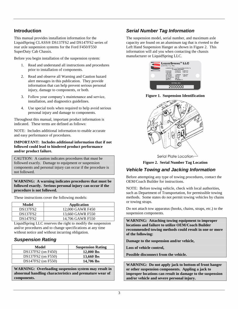
Serial Number Tag Information
The suspension model, serial number, and maximum axle
capacity are found on an aluminum tag that is riveted to the
Left Hand Suspension Hanger as shown in Figure 2. This
information will aid you when contacting the chassis
manufacturer or LiquidSpring LLC.
Figure 1. Suspension Identification
Figure 2. Serial Number Tag Location
Vehicle Towing and Jacking Information
Before attempting any type of towing procedures, contact the
OEM/Coach Builder for instructions.
NOTE: Before towing vehicle, check with local authorities,
such as Department of Transportation, for permissible towing
methods. Some states do not permit towing vehicles by chains
or towing straps.
Do not attach tow apparatus (hooks, chains, straps, etc.) to the
suspension components.
WARNING: Attaching towing equipment to improper
locations and failure to utilize OEM/Coach Builder
recommended towing methods could result in one or more
of the following:
Damage to the suspension and/or vehicle,
Loss of vehicle control,
Possible disconnect from the vehicle.
WARNING: Do not apply jack to bottom of front hanger
or other suspension components. Appling a jack to
improper locations can result in damage to the suspension
and/or vehicle and severe personal injury.

4
Hydraulic Fitting Assembly
SAE O-Ring Adjustable Fittings
Figure 3. Adjustable SAE fitting
1. Inspect components to ensure that male and female
port threads and sealing surfaces are free of burrs,
nicks and scratches, or any foreign material.
2. If O-ring or seal is not pre-installed to fitting male
port end, install proper size O-ring or seal, taking
care not to damage it.
3. Lubricate O-ring with light coat of the system fluid or
a compatible lubricant to help the O-ring slide
smoothly into the port and avoid damage.
Figure 4. Locknut completely backed off.
4. Back off lock nut as far as possible. Make sure back-
up washer is not loose and is pushed up as far as
possible.
5. Screw fitting into port until the back-up washer or the
retaining ring contacts face of the port. Light
wrenching may be necessary. Over tightening may
damage washer.
6. To align the tube end of the fitting to accept
incoming hose assembly, unscrew the fitting by the
required amount, but not more than one full turn.
7. Using two wrenches, hold fitting in desired position
and tighten locknut to the proper torque value:
-4 fitting: 14-16 ft-lbs (168-192 in-lbs)
-12 fitting: 75-83 ft-lbs.
8. Inspect to ensure that O-ring is not pinched and that
washer is seated flat on face of port.
SAE O-Ring Non-Adjustable Fitting
1. Inspect components to ensure that male and female
port threads and sealing surfaces are free of burrs,
nicks and scratches, or any foreign material.
2. If O-ring or seal is not pre-installed to fitting male
port end, install proper size O-ring or seal, taking
care not to damage it.
3. Lubricate O-ring with light coat of the system fluid or
a compatible lubricant to help the O-ring slide
smoothly into the port and avoid damage.
4. Screw fitting into port and tighten to proper torque:
-4 fitting: 26-28 ft-lbs (310-341 in-lbs)
-12 fitting: 75-83 ft-lbs.
JIC 37° Fitting
1. Inspect components to ensure that male and female
threads and sealing surfaces are free of burrs, nicks
and scratches, or any foreign material. Annular tool
marks of 100µin with the thread are permissible.
2. Lubricate the threads and the entire surface of the
cone with system fluid.
3. Align mating components for hand connection and
turn flare nut until sealing surfaces make full contact.
4. Using two wrenches, hold fitting in desired position
and tighten to the proper torque:
-4 fitting: 9-12 ft-lbs
-8 fitting: 27-39 ft-lbs
-10 fitting: 36-63 ft-lbs
-12 fitting: 65-88 ft-lbs.

5
Pre-Installation
1. Check the vehicle wheel alignment prior to
installation to insure pre-existing conditions do not
exist.
2. It is suggested, but not required, to remove the
attached body to ease installation.
3. A chassis lift can be used in assistance of the
installation of the suspension system.
4. Measure and record the wheelbase and tire-to-frame
dimensions on each side prior to disassembly.
Frame Preparation
1. Chock the front tires.
2. Jack up the rear frame of the vehicle to remove the
load from the rear leaf springs.
3. Place jack stands under the frame and block the rear
tires from moving.
Note: Jack stands can be placed under the axle and the
tires removed for ease of access. It is recommended to
place an additional jack stand under the pinion to prevent
the axle from rotating.
4. Disconnect the negative cable from the vehicle
battery.
5. Remove the OEM shock absorbers.
6. Remove the OEM leaf springs and rear shackles.
7. If equipped with the midship fuel tank, dropping the
tank may ease installation.
8. Remove the OEM Axle Stop Bumpers from under
the frame.
9. Remove the driver side Parking Brake Cable wire
form brackets and position the cable and conduit
aside.
10. Remove the passenger side Parking Brake Cable wire
form brackets from the driver side frame rail and
position the cable and conduit aside.
11. Remove the overload pads.
12. Remove the Driver side shock mount riveted to the
frame.
13. Locate the drilling template and follow the instructions in
Appendix A: Frame Drilling Locations, page 42, for
drilling holes in the frame rail.
Figure 5. Location of Drilling Template on Driver Side
Frame.
Note: See Secondary Volumes, page 21 and 22, for additional
frame drill requirements.

6
Parts List Information Abbreviations
HCS Hex Cap Screw
HFB Hex Flange Bolt
SHCS Socket Head Cap Screw
SFHS Serrated Flange Hex Screw
HN Hex Nut, Non-locking
LHN Locking Hex Nut
LFN Locking Flange Nut
CHN Castle Hex Nut
HTCN Hex Thin Castle Nut
HFW Hardened Flat Washer
SLW Spring Lock Washer
SAE SAE O-Ring Fitting
37° SAE or JIC 37° Flare Fitting
LH Left Handed Part
RH Right Handed Part
Special Tools
The following tools can assist in installation of the
LiquidSpring system.
Bleed Kit (Actron 7840 shown, others similar).

7
Installation Overall
Suspension Layout (DS137FS2)
8
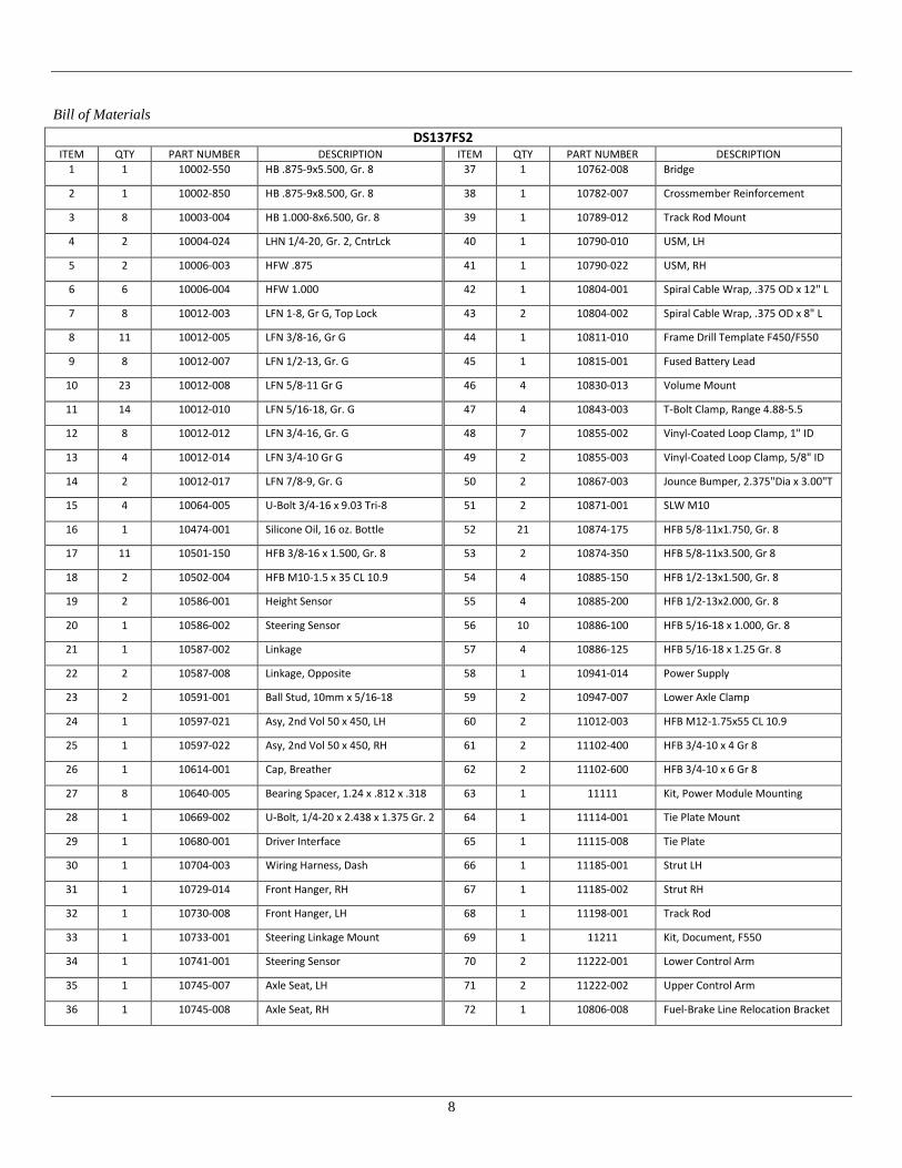
Bill of Materials
DS137FS2
ITEM QTY PART NUMBER DESCRIPTION ITEM QTY PART NUMBER DESCRIPTION
1 1 10002-550 HB .875-9x5.500, Gr. 8 37 1 10762-008 Bridge
2 1 10002-850 HB .875-9x8.500, Gr. 8 38 1 10782-007 Crossmember Reinforcement
3 8 10003-004 HB 1.000-8x6.500, Gr. 8 39 1 10789-012 Track Rod Mount
4 2 10004-024 LHN 1/4-20, Gr. 2, CntrLck 40 1 10790-010 USM, LH
5 2 10006-003 HFW .875 41 1 10790-022 USM, RH
6 6 10006-004 HFW 1.000 42 1 10804-001 Spiral Cable Wrap, .375 OD x 12" L
7 8 10012-003 LFN 1-8, Gr G, Top Lock 43 2 10804-002 Spiral Cable Wrap, .375 OD x 8" L
8 11 10012-005 LFN 3/8-16, Gr G 44 1 10811-010 Frame Drill Template F450/F550
9 8 10012-007 LFN 1/2-13, Gr. G 45 1 10815-001 Fused Battery Lead
10 23 10012-008 LFN 5/8-11 Gr G 46 4 10830-013 Volume Mount
11 14 10012-010 LFN 5/16-18, Gr. G 47 4 10843-003 T-Bolt Clamp, Range 4.88-5.5
12 8 10012-012 LFN 3/4-16, Gr. G 48 7 10855-002 Vinyl-Coated Loop Clamp, 1" ID
13 4 10012-014 LFN 3/4-10 Gr G 49 2 10855-003 Vinyl-Coated Loop Clamp, 5/8" ID
14 2 10012-017 LFN 7/8-9, Gr. G 50 2 10867-003 Jounce Bumper, 2.375"Dia x 3.00"T
15 4 10064-005 U-Bolt 3/4-16 x 9.03 Tri-8 51 2 10871-001 SLW M10
16 1 10474-001 Silicone Oil, 16 oz. Bottle 52 21 10874-175 HFB 5/8-11x1.750, Gr. 8
17 11 10501-150 HFB 3/8-16 x 1.500, Gr. 8 53 2 10874-350 HFB 5/8-11x3.500, Gr 8
18 2 10502-004 HFB M10-1.5 x 35 CL 10.9 54 4 10885-150 HFB 1/2-13x1.500, Gr. 8
19 2 10586-001 Height Sensor 55 4 10885-200 HFB 1/2-13x2.000, Gr. 8
20 1 10586-002 Steering Sensor 56 10 10886-100 HFB 5/16-18 x 1.000, Gr. 8
21 1 10587-002 Linkage 57 4 10886-125 HFB 5/16-18 x 1.25 Gr. 8
22 2 10587-008 Linkage, Opposite 58 1 10941-014 Power Supply
23 2 10591-001 Ball Stud, 10mm x 5/16-18 59 2 10947-007 Lower Axle Clamp
24 1 10597-021 Asy, 2nd Vol 50 x 450, LH 60 2 11012-003 HFB M12-1.75x55 CL 10.9
25 1 10597-022 Asy, 2nd Vol 50 x 450, RH 61 2 11102-400 HFB 3/4-10 x 4 Gr 8
26 1 10614-001 Cap, Breather 62 2 11102-600 HFB 3/4-10 x 6 Gr 8
27 8 10640-005 Bearing Spacer, 1.24 x .812 x .318 63 1 11111 Kit, Power Module Mounting
28 1 10669-002 U-Bolt, 1/4-20 x 2.438 x 1.375 Gr. 2 64 1 11114-001 Tie Plate Mount
29 1 10680-001 Driver Interface 65 1 11115-008 Tie Plate
30 1 10704-003 Wiring Harness, Dash 66 1 11185-001 Strut LH
31 1 10729-014 Front Hanger, RH 67 1 11185-002 Strut RH
32 1 10730-008 Front Hanger, LH 68 1 11198-001 Track Rod
33 1 10733-001 Steering Linkage Mount 69 1 11211 Kit, Document, F550
34 1 10741-001 Steering Sensor 70 2 11222-001 Lower Control Arm
35 1 10745-007 Axle Seat, LH 71 2 11222-002 Upper Control Arm
36 1 10745-008 Axle Seat, RH 72 1 10806-008 Fuel-Brake Line Relocation Bracket
9
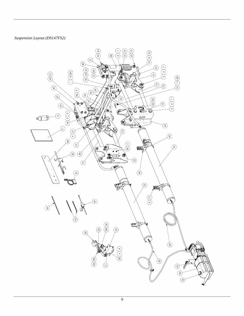
Suspension Layout (DS147FS2)

10
Bill of Materials
DS147FS2
ITEM QTY PART NUMBER DESCRIPTION ITEM QTY PART NUMBER DESCRIPTION
1 1 10002-550 HB .875-9x5.500, Gr. 8 38 1 10745-008 Axle Seat, RH
2 1 10002-850 HB .875-9x8.500, Gr. 8 39 1 10762-008 Bridge
3 8 10003-004 HB 1.000-8x6.500, Gr. 8 40 1 10782-007 Crossmember Reinforcement
4 2 10004-024 LHN 1/4-20, Gr. 2, CntrLck 41 1 10789-012 Track Rod Mount
5 2 10006-003 HFW .875 42 1 10790-010 USM, LH
6 6 10006-004 HFW 1.000 43 1 10790-022 USM, RH
7 8 10012-003 LFN 1-8, Gr G, Top Lock 44 1 10804-001 Spiral Cable Wrap, .375 OD x 12" L
8 11 10012-005 LFN 3/8-16, Gr G 45 2 10804-002 Spiral Cable Wrap, .375 OD x 8" L
9 8 10012-007 LFN 1/2-13, Gr. G 46 1 10811-010 Frame Drill Template F450/F550
10 23 10012-008 LFN 5/8-11 Gr G 47 1 10815-001 Fused Battery Lead
11 14 10012-010 LFN 5/16-18, Gr. G 48 4 10830-013 Volume Mount
12 8 10012-012 LFN 3/4-16, Gr. G 49 4 10843-003 T-Bolt Clamp, Range 4.88-5.5
13 4 10012-014 LFN 3/4-10 Gr G 50 7 10855-002 Vinyl-Coated Loop Clamp, 1" ID
14 2 10012-017 LFN 7/8-9, Gr. G 51 2 10855-003 Vinyl-Coated Loop Clamp, 5/8" ID
15 4 10064-005 U-Bolt 3/4-16 x 9.03 Tri-8 52 2 10867-003 Jounce Bumper, 2.375"Dia x 3.00"T
16 1 10474-001 Silicone Oil, 16 oz. Bottle 53 2 10871-001 SLW M10
17 11 10501-150 HFB 3/8-16 x 1.500, Gr. 8 54 21 10874-175 HFB 5/8-11x1.750, Gr. 8
18 2 10502-004 HFB M10-1.5 x 35 CL 10.9 55 2 10874-350 HFB 5/8-11x3.500, Gr 8
19 2 10586-001 Height Sensor 56 4 10885-150 HFB 1/2-13x1.500, Gr. 8
20 1 10586-002 Steering Sensor 57 4 10885-200 HFB 1/2-13x2.000, Gr. 8
21 1 10587-002 Linkage 58 10 10886-100 HFB 5/16-18 x 1.000, Gr. 8
22 2 10587-008 Linkage, Opposite 59 4 10886-125 HFB 5/16-18 x 1.25 Gr. 8
23 2 10591-001 Ball Stud, 10mm x 5/16-18 60 1 10941-014 Power Supply
24 1 10597-013 Asy, 2nd Vol 108 x 539, LH 61 2 10947-007 Lower Axle Clamp
25 1 10597-014 Asy, 2nd Vol 108 x 539, RH 62 2 11012-003 HFB M12-1.75x55 CL 10.9
26 1 10614-001 Cap, Breather 63 2 11102-400 HFB 3/4-10 x 4 Gr 8
27 8 10640-005 Bearing Spacer, 1.24 x .812 x .318 64 2 11102-600 HFB 3/4-10 x 6 Gr 8
28 1 10669-002 U-Bolt, 1/4-20 x 2.438 x 1.375 Gr. 2 65 1 11111 Kit, Power Module Mounting
29 1 10675-009 Asy, Hose, -4 x 129-7/8” 66 1 11114-001 Tie Plate Mount
30 1 10675-010 Asy, Hose, -4 x 176-1/2” 67 1 11115-008 Tie Plate
31 1 10680-001 Driver Interface 68 1 11177-003 Strut LH
32 1 10704-003 Wiring Harness, Dash 69 1 11177-004 Strut RH
33 1 10729-014 Front Hanger, RH 70 1 11198-001 Track Rod
34 1 10730-008 Front Hanger, LH 71 1 11211 Kit, Document, F550
35 1 10733-001 Steering Linkage Mount 72 2 11222-001 Lower Control Arm
36 1 10741-001 Steering Sensor 73 2 11222-002 Upper Control Arm
37 1 10745-007 Axle Seat, LH 74 1 10806-008 Fuel-Brake Line Relocation Bracket

11
Front Hangers
ITEM QTY PART NUMBER DESCRIPTION ITEM QTY PART NUMBER DESCRIPTION
1 8 10012-008 LFN 5/8-11 Gr. G 3* 1 10729-007 (S/N: 2001858 and Older) Front Hanger, RH
10729-014 (S/N: 2001859 and Newer)
2 8 10874-175 HFB 5/8-11x1.75”, Gr. 8 4* 1 10730-004 (S/N: 2001858 and Older) Front Hanger, LH
10730-008 (S/N: 2001859 and Newer)
*IMPORTANT: Items marked with Asterisk are non-interchangeable with Older/Newer serial numbers. See Appendix B:
Part Number Compatibility – Serial Number Cutoff, Page 43 for more information.
1. Install the hangers as shown with supplied fasteners
through OEM front hanger holes.
Note: Snug OEM fasteners on frame flange prior to
tightening 5/8” fasteners to ensure hanger is flush with
bottom of frame rail.
2. Torque Fasteners to 172-210 ft-lbs.
12
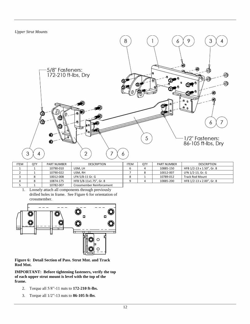
Upper Strut Mounts
ITEM QTY PART NUMBER DESCRIPTION ITEM QTY PART NUMBER DESCRIPTION
1 1 10790-010 USM, LH 6 4 10885-150 HFB 1/2-13 x 1.50”, Gr. 8
2 1 10790-022 USM, RH 7 8 10012-007 LFN 1/2-13, Gr. G
3 8 10012-008 LFN 5/8-11 Gr. G 8 1 10789-012 Track Rod Mount
4 8 10874-175 HFB 5/8-11x1.75”, Gr. 8 9 4 10885-200 HFB 1/2-13 x 2.00”, Gr. 8
5 1 10782-007 Crossmember Reinforcement
1. Loosely attach all components through previously
drilled holes in frame. See Figure 6 for orientation of
crossmember.
Figure 6: Detail Section of Pass. Strut Mnt. and Track
Rod Mnt.
IMPORTANT: Before tightening fasteners, verify the top
of each upper strut mount is level with the top of the
frame.
2. Torque all 5/8”-11 nuts to 172-210 ft-lbs.
3. Torque all 1/2”-13 nuts to 86-105 ft-lbs.

13
Axle Clamp Hangers
ITEM QTY PART NUMBER DESCRIPTION ITEM QTY PART NUMBER DESCRIPTION
1 2 10012-008 LFN 5/8-11 Gr. G 5 2* 10947-004 (S/N: 2001858 and Older) Lower Axle Clamp
10947-007 (S/N: 2001859 and Newer)
2 4 10064-005 U-Bolt ¾-16 x 9.03 Tri-8 6 2* 10745-005 (S/N: 2001858 and Older) Axle Seat, LH
10745-007 (S/N: 2001859 and Newer)
3 8 10012-012 LFN ¾-16, Gr. G 7 1* 10745-006 (S/N: 2001858 and Older) Axle Seat, RH
10745-008 (S/N: 2001859 and Newer)
4 2 10874-350 HFB 5/8-11x3.50, Gr. 8
*IMPORTANT: Items marked with Asterisk are non-interchangeable with Older/Newer serial numbers. See Appendix B:
Part Number Compatibility – Serial Number Cutoff, Page 43 for more information.
IMPORTANT: When installing Upper axle Seats refer to
Figure 7 for aligning parts.
IMPORTANT: Leave OEM brake lines attached to the
axle seat when installing components. See Figure 7
Figure 7: Use Swaybar Mount for Aligning Axle Mount
Note: Remove both top sway bar bolts from the axle.
1. Install Components as shown above with M12
fasteners from Bridge installation for temporarily
aligning parts.
2. Torque, the U-bolt nuts evenly in an X-type
pattern in 4 stages:
Stage 1: Tighten snug only.
Stage 2: Torque to 100 ft-lbs.
Stage 3: Torque to 200 ft-lbs.
Stage 4: Torque to 300 ft-lbs].
IMPORTANT: Use of high speed impact gun may result
in galling of threads. Anti-Seize may be used to lubricate
U-bolt threads, but all torque values must be reduced by
20%: 100 ft-lbs 80 ft-lbs; 200 ft-lbs 160 ft-lbs; 300 ft-
lbs 240 ft-lbs.
3. Torque 5/8” Fasteners to 172-210 ft-lbs.
4. Remove temporary M12 bolt from swaybar mounting
hole in both Driver and Passenger sides.

14
Control Arms
ITEM QTY PART NUMBER DESCRIPTION ITEM QTY PART NUMBER DESCRIPTION
1 8 10012-003 LFN 1-8, Gr G 4* 2 10720-002 (S/N: 2001858 and Older) UCA
11222-002 (S/N: 2001859 and Newer)
2 6 10006-004 HFW 1.00 5* 2 10720-003 (S/N: 2001858 and Older) LCA
11222-001 (S/N: 2001859 and Newer)
3 8 10003-004 HB 1.00-8 x 6.50, Gr. 8
*IMPORTANT: Items marked with Asterisk are non-interchangeable with Older/Newer serial numbers. See Appendix B:
Part Number Compatibility – Serial Number Cutoff, Page 43 for more information.
1. Locate control arms and install as shown.
Note: Height sensor tab located on Lower Control
arm must be pointing up and closest to front hanger.
IMPORTANT: Only torque fasteners when suspension is
sitting at ride height. Not doing so will result in premature
wear or failure of bushings. See Figure 13 on Page 17

15
Bridge
ITEM QTY PART NUMBER DESCRIPTION ITEM QTY PART NUMBER DESCRIPTION
1 4 10012-008 LFN 5/8-11 Gr. G 4 1 10762-008 Bridge
2 4 10874-175 HFB 5/8-11x1.75”, Gr. 8 5 1 10804-001 Spiral Cable Wrap 3/8 OD x 12” L
3 2 11012-003 HFB M12-1.75x55 CL 10.9
Install Bridge as shown above.
1. The M12 Fasteners will fasten to the OEM swaybar
mount. Torque M12 fasteners to 75-91 Ft-lbs, Dry.
2. Torque 5/8” Fasteners to 172-210 Ft-lbs, Dry.
Figure 8: Install Spiral wrap around hydraulic brake line
where it contacts bridge. Note: View is looking from
underside behind the axle.
3. Included in the kit is a 12” long piece of nylon spiral
wrap. Install the spiral wrap as shown in Figure 8 to
protect the hydraulic brake line from chafing against
the track rod bridge. Note: The hydraulic line routes
from the crossmember to the axle

16
Track Rod
ITEM QTY PART NUMBER DESCRIPTION ITEM QTY PART NUMBER DESCRIPTION
1 1 10012-008 LFN 5/8-11 Gr. G 8 1 11114-001 Tie Plate Mount
2 1 10874-175 HFB 5/8-11 x 1.75, Gr. 8 9 1 11115-008 Tie Plate
3 1 11198-001 Track Rod 10 1 10002-850 HB .875-9x8.500, Gr. 8
4 2 10006-003 HFW .875 11 1 10002-550 HB .875-9x5.500, Gr. 8
5 2 10012-017 LFN 7/8-9, Gr. G 12 1 10012-010 LHN 5/16-18 Gr. G
6 3 10012-005 LFN 3/8-16, Gr. G 13 1 10886-100 FHB 5/16-18 x 1.00 Gr. 8
7 3 10501-150 HFB 3/8-16 x 1.50, Gr. 8 14 1 10806-008 Fuel-Brake Line Relocation Bracket
1. Disconnect the (2) Factory Fuel and Brake line
retainers, as circled in Figure 9, from the frame.
Keep lines attached to the retainers.
Figure 9. Fuel and Brake Line Retainers to disconnect
2. Install Tie Plate Weldment where Driver side shock
mount was previously located. The rearmost shock
mount hole will need enlarged to 13/32” for
accepting a 3/8” fastener.
3. Install the Fuel-Brake Line Relocation Bracket into
the same mount hole which the factory retainer,
located in front of the shock absorber, was attached.
Figure 10. Relocation Bracket placement
4. Attach the factory retainers, with the lines attached,
atop the Tie Plate Mount and Fuel-Brake Line
Relocation Brackets as shown in Figure 10.

17
Figure 11 Fuel Lines route over top of Tie Bar Mount
Figure 12 Fasten OEM Bracket to top of Tie Bar Mount
5. Install Tie Bar and Track rod as shown in exploded
view.
Note: Install fasteners oriented as shown.
6. Raise or Lower Axle until Design Ride height is
achieved. Ride Height is approximately when the
track rod is horizontal and when CL of axle to bottom
of frame is 11”. See Figure 13.
Figure 13: Ride Height Dimensions
7. Torque the two (2) 7/8” Track Rod mounting bolts to
491-600 ft-lbs.
8. Final Torque the (8) 1-8 Control Arm mounting bolts
previously installed to 600 ft-lbs.

18
Strut Assembly Installation
DS137FS2
ITEM QTY PART NUMBER DESCRIPTION ITEM QTY PART NUMBER DESCRIPTION
1 4 10012-014 LFN 3/4-10 Gr. G 4 2 11102-600 HFB 3/4-10 x 6 Gr. 8
2 8 10640-005 Bearing Spacer, 1.24 x .812 x .318 5 1 11185-001 LH Strut Assembly
3 2 11102-400 HFB 3/4-10 x 4 Gr. 8 6 1 11185-002 RH Strut Assembly
DS147FS2
ITEM QTY PART NUMBER DESCRIPTION ITEM QTY PART NUMBER DESCRIPTION
1 4 10012-014 LFN 3/4-10 Gr. G 4 2 11102-600 HFB 3/4-10 x 6 Gr. 8
2 8 10640-005 Bearing Spacer, 1.24 x .812 x .318 5 1 11177-003 LH Strut Assembly
3 2 11102-400 HFB 3/4-10 x 4 Gr. 8 6 1 11177-004 RH Strut Assembly
1. Install Struts as shown above with -10 fittings
pointing forward.
2. Torque 3/4-10 fasteners to 275-300 ft-lbs, Dry.
3. Included in the kit are two 8” sections of nylon spiral
wrap (P/N: 10804-002). Install the spiral wrap as
shown in Figure 14 to protect the hydraulic brake
lines from chafing against the strut boots.
Figure 14: Install spiral wrap around brake whip hoses,
on Driver and Passenger sides
19
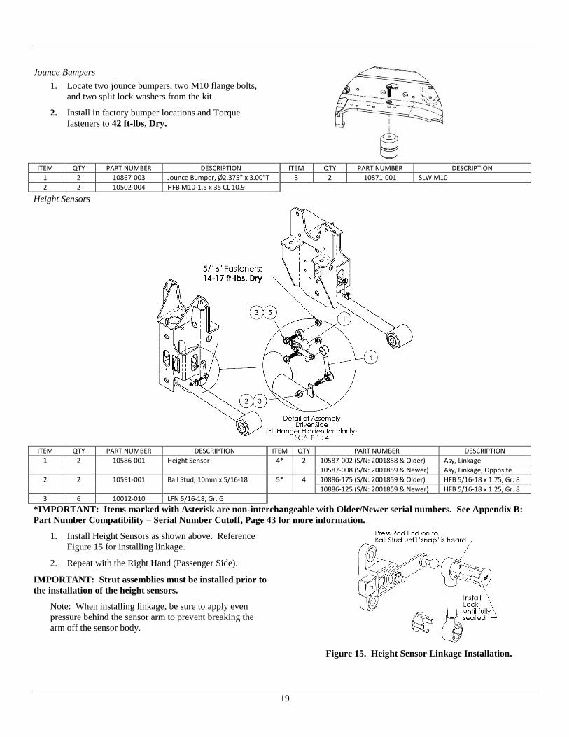
Jounce Bumpers
1. Locate two jounce bumpers, two M10 flange bolts,
and two split lock washers from the kit.
2. Install in factory bumper locations and Torque
fasteners to 42 ft-lbs, Dry.
ITEM QTY PART NUMBER DESCRIPTION ITEM QTY PART NUMBER DESCRIPTION
1 2 10867-003 Jounce Bumper, Ø2.375” x 3.00”T 3 2 10871-001 SLW M10
2 2 10502-004 HFB M10-1.5 x 35 CL 10.9
Height Sensors
ITEM QTY PART NUMBER DESCRIPTION ITEM QTY PART NUMBER DESCRIPTION
1 2 10586-001 Height Sensor 4* 2 10587-002 (S/N: 2001858 & Older) Asy, Linkage
10587-008 (S/N: 2001859 & Newer) Asy, Linkage, Opposite
2 2 10591-001 Ball Stud, 10mm x 5/16-18 5* 4 10886-175 (S/N: 2001859 & Older) HFB 5/16-18 x 1.75, Gr. 8
10886-125 (S/N: 2001859 & Newer) HFB 5/16-18 x 1.25, Gr. 8
3 6 10012-010 LFN 5/16-18, Gr. G
*IMPORTANT: Items marked with Asterisk are non-interchangeable with Older/Newer serial numbers. See Appendix B:
Part Number Compatibility – Serial Number Cutoff, Page 43 for more information.
1. Install Height Sensors as shown above. Reference
Figure 15 for installing linkage.
2. Repeat with the Right Hand (Passenger Side).
IMPORTANT: Strut assemblies must be installed prior to
the installation of the height sensors.
Note: When installing linkage, be sure to apply even
pressure behind the sensor arm to prevent breaking the
arm off the sensor body.
Figure 15. Height Sensor Linkage Installation.

20
Power Module Installation
ITEM QTY PART NUMBER DESCRIPTION ITEM QTY PART NUMBER DESCRIPTION
1 3 10012-011 LFN 3/8-16, Gr. G, Nylon Top 8 1 10799-014 Manifold Mount
2 2 10088-001 FW #10 9 2 10805-004 Grommet, .19 ID x .56 OD x .375 T
3 2 10252-003 SFHS 3/8-16 x .625, Gr 8 10 1 10865-003 J-Bolt, 3/8-16 x 4” L
4 2 10322-021 Hyd Fit 90, -4 37 x -4 37 F 11 1 10865-004 J-Bolt, 3/8-16 x 6” L
5 1 10501-002 HFB 3/8-16 x 1.25, Gr 8 12 2 11207-002 HFB M5-0.8 x 12 CL 10.9
6 2 10510-002 STS #10-16 x .75, Hex Head 13 1 10941-014 Power Module
7 1 10798-014 Reservoir Mount
1. Locate the Power Module Assembly and Power
Module Mounting Kit.
2. Follow instructions supplied with the hardware for
attaching brackets to the power module.

21
Secondary Volumes (DS137FS2)
ITEM QTY PART NUMBER DESCRIPTION ITEM QTY PART NUMBER DESCRIPTION
1 7 11012-010 LFN 5/16-18, Gr. G 7 4 10843-003 T-Bolt Clamp, Range 4.88-5.5
2 7 10886-100 HFB 5/16”-18 x 1.00” Gr 8 8 7 10855-002 Vinyl Coated Loop Clamp, 1” ID
3 1 10614-001 Breather Cap 9 2 10855-003 Vinyl Coated Loop Clamp, 5/8” ID
4 1 10597-021 Asy, 2nd Volume, LH 10 8 10012-005 LFN 3/8-16, Gr. G
5 1 10597-022 Asy, 2nd Volume, RH 11 8 10501-150 HFB 3/8-16 x 1.50, Gr. 8
6 4 10830-013 Volume Mount
1. Place the mounts against the driver side frame,
forward of the front hanger.
2. Verifying the mounts are held flush to the bottom of
the frame and utilizing the mount hole pattern, mark
the locations of the mounting holes and drill (2)
Ø7/16” holes per mount. Refer to Figure 16 for
drilling locations.
3. Repeat with (2) more Volume Mount Weldments on
the passenger side of the frame. Refer to Figure 16
for drilling locations.
4. Install Volume mounting brackets, volumes, and
route hoses as shown.
Figure 16. Secondary Volume Mount Locations

22
Secondary Volumes (DS147FS2)
ITEM QTY PART NUMBER DESCRIPTION ITEM QTY PART NUMBER DESCRIPTION
1 7 11012-010 LFN 5/16-18, Gr. G 7 4 10843-003 T-Bolt Clamp, Range 4.88-5.5
2 7 10886-100 HFB 5/16”-18 x 1.00” Gr 8 8 7 10855-002 Vinyl Coated Loop Clamp, 1” ID
3 1 10614-001 Breather Cap 9 2 10855-003 Vinyl Coated Loop Clamp, 5/8” ID
4 1 10597-013 Asy, 2nd Volume, LH 10 8 10012-005 LFN 3/8-16, Gr. G
5 1 10597-014 Asy, 2nd Volume, RH 11 8 10501-150 HFB 3/8-16 x 1.50, Gr. 8
6 4 10830-013 Volume Mount
5. Place the mounts against the driver side frame,
forward of the front hanger.
6. Verifying the mounts are held flush to the bottom of
the frame and utilizing the mount hole pattern, mark
the locations of the mounting holes and drill (2)
Ø7/16” holes per mount. Refer to Figure 16 for
drilling locations.
7. Repeat with (2) more Volume Mount Weldments on
the passenger side of the frame. Refer to Figure 16
for drilling locations.
8. Install Volume mounting brackets, volumes, and
route hoses as shown.
Figure 17. Secondary Volume Mount Locations
23
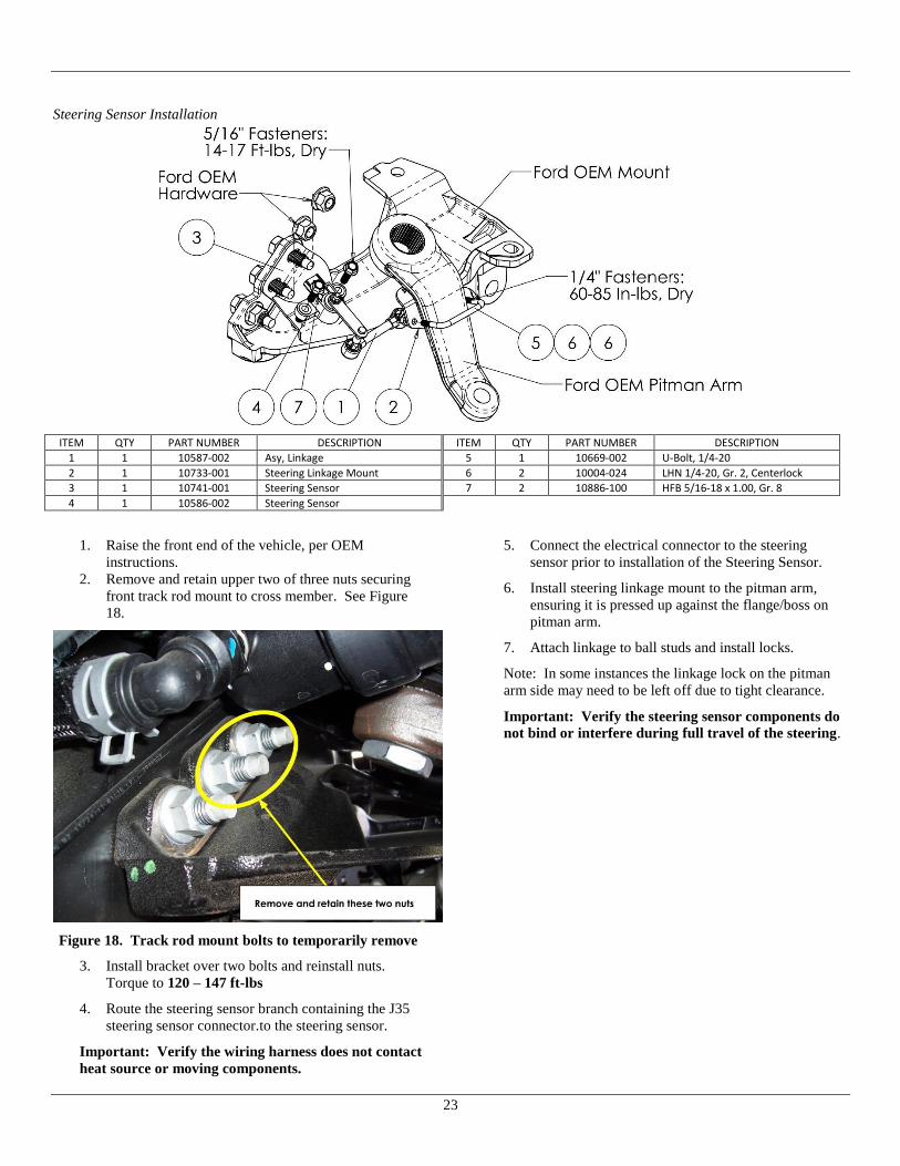
Steering Sensor Installation
ITEM QTY PART NUMBER DESCRIPTION ITEM QTY PART NUMBER DESCRIPTION
1 1 10587-002 Asy, Linkage 5 1 10669-002 U-Bolt, 1/4-20
2 1 10733-001 Steering Linkage Mount 6 2 10004-024 LHN 1/4-20, Gr. 2, Centerlock
3 1 10741-001 Steering Sensor 7 2 10886-100 HFB 5/16-18 x 1.00, Gr. 8
4 1 10586-002 Steering Sensor
1. Raise the front end of the vehicle, per OEM
instructions.
2. Remove and retain upper two of three nuts securing
front track rod mount to cross member. See Figure
18.
Figure 18. Track rod mount bolts to temporarily remove
3. Install bracket over two bolts and reinstall nuts.
Torque to 120 – 147 ft-lbs
4. Route the steering sensor branch containing the J35
steering sensor connector.to the steering sensor.
Important: Verify the wiring harness does not contact
heat source or moving components.
5. Connect the electrical connector to the steering
sensor prior to installation of the Steering Sensor.
6. Install steering linkage mount to the pitman arm,
ensuring it is pressed up against the flange/boss on
pitman arm.
7. Attach linkage to ball studs and install locks.
Note: In some instances the linkage lock on the pitman
arm side may need to be left off due to tight clearance.
Important: Verify the steering sensor components do
not bind or interfere during full travel of the steering.
24
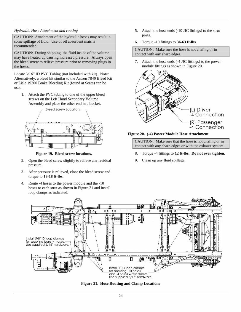
Hydraulic Hose Attachment and routing
CAUTION: Attachment of the hydraulic hoses may result in
some spillage of fluid. Use of oil absorbent mats is
recommended.
CAUTION: During shipping, the fluid inside of the volume
may have heated up causing increased pressure. Always open
the bleed screw to relieve pressure prior to removing plugs in
the hoses.
Locate 3/16” ID PVC Tubing (not included with kit). Note:
Alternatively, a bleed kit similar to the Actron 7840 Bleed Kit
or Lisle 19200 Brake Bleeding Kit (found at Sears) can be
used.
1. Attach the PVC tubing to one of the upper bleed
screws on the Left Hand Secondary Volume
Assembly and place the other end in a bucket.
Figure 19. Bleed screw locations.
2. Open the bleed screw slightly to relieve any residual
pressure.
3. After pressure is relieved, close the bleed screw and
torque to 13-18 ft-lbs.
4. Route -4 hoses to the power module and the -10
hoses to each strut as shown in Figure 21 and install
loop clamps as indicated.
5. Attach the hose ends (-10 JIC fittings) to the strut
ports.
6. Torque -10 fittings to 36-63 ft-lbs.
CAUTION: Make sure the hose is not chafing or in
contact with any sharp edges.
7. Attach the hose ends (-4 JIC fittings) to the power
module fittings as shown in Figure 20.
Figure 20. (-4) Power Module Hose Attachment
CAUTION: Make sure that the hose is not chafing or in
contact with any sharp edges or with the exhaust system.
8. Torque -4 fittings to 12 ft-lbs. Do not over tighten.
9. Clean up any fluid spillage.
Figure 21. Hose Routing and Clamp Locations

25
Parking Brake Cable
1. Route Passenger side Parking brake cable through
grommets in LH Front Hanger and re-attach in OEM
locations. See Figure 22
Figure 22: Route parking brake cable through LH Hanger
2. Make sure the Passenger Parking brake cable routes
above the Lower control arm as shown below. Note:
Bend the OEM cable standoff up to allow clearance.
3. Re-attach the Driver Side parking brake cable in
OEM locations. Cable will pass between the upper
and lower control arms on the driver side.
CAUTION: Make sure the cables are not chafing or in
contact with any sharp edges.
External Electrical Installation:
1. Locate the External Electrical Harness attached to the
power module.
2. Unroll the wiring harness and using the External
Electrical Harness wiring diagram, found in the
electrical schematics section, and identify the
connection ends.
3. Locate the trunk containing Height Sensor (J21 and
J22) and the Rate Valve (J23 and J24) connections.
4. Route and make the following connections to the
Height Sensors.
J21 Left Height Sensor
J22 Right Height Sensor
5. Route and make the following connections to the
Rate Valves.
J23 Left Rate Valve
J24 Right Rate Valve
6. Secure harness to OEM harness. Use of plastic clips
is recommended.
7. Locate the 8ga wire ground ring terminal, J30, branch
near the power module.
8. Locate and drill Ø1/4” hole in frame. Remove frame
coating(s) as needed to ensure metal-to-metal contact
between the ring terminal and frame.
9. Attach the ground ring terminal, J30, to the chassis
frame for grounding. Sealant may be applied after
ring terminal is secured.
10. Route the remaining trunk (containing blunt wires
and steering sensor connector) towards the firewall.
Secure to OEM wiring harness.
11. Locate the existing firewall access hole under the
dash, behind the brake pedal and just above the OEM
customer access upfitter wiring.
12. Route the wiring harness branch containing the (8)
18ga blunt wires through the firewall access hole.
13. Locate the 8ga battery connection branch.
14. Route branch to the driver side battery positive
terminal.
15. Locate the Battery Fuse Lead containing the 80 amp
fuse.
16. Crimp the fuse lead to the 8ga battery connection
branch blunt end.
17. Melt the heat shrink on the crimped connection to
seal the splice.
18. Remove the 80 amp fuse and retain.
19. Connect to the positive terminal post per OEM
Upfitter wiring instructions.
Figure 23. OEM Upfitter Driver Side Terminal
Connection instruction.
Important: Do not connect to passenger side
battery.

26
Dash Electrical Harness Installation:
1. Locate the dash harness.
2. Locate and identify the following 18ga wires in the
external wiring harness branch passed through the
firewall:
Red (Battery Power)
Yellow (Ignition)
Black (Ground)
White (CAN High)
White/Black (CAN Low)
Violet/White (Speed)
Pink/Black (Brake)
3. Connect each wire to the corresponding wire in the
dash harness using appropriate butt splices. Match
wire colors. Heat shrink sealing is optional.
Figure 24. Accessing inside of side kick panel.
4. Remove outboard side kick panel, from around
parking brake.
5. Locate dash harness.
6. Attach ring terminal J32 to ground screw.
Figure 25. Location of ground connection.
7. Locate the OEM customer access upfitter wiring,
under the dash, behind the brake pedal. Figure 26.
Figure 26. Customer Access wires.
Figure 27. Customer access wires utilized.
8. Remove some of the electrical tape to reveal the
blunt-cut wires.
9. In the OEM Upfitter wiring bundle, locate the “VS
OUT”, Violet/Orange, wire and strip end.
10. Splice the Violet/Orange to the dash harness
Violet/White (W55) wire, using the appropriate butt
splice and crimp. Reference the Dash Harness
Schematic.
11. In the OEM upfitter wiring bundle, locate the
“RUN/ACC”, White/Blue, wire and strip end.
12. Splice the White/Blue end to the dash harness Yellow
only (W58) wire, using the appropriate butt splice,
and crimp. Reference the Dash Harness Schematic.
13. In the OEM upfitter wiring bundle, locate the “TRO
P”, Blue/Grey, wire and strip end.
14. Splice the Blue/Grey end to the dash harness
Yellow/Black (W61) wire, using the appropriate butt
splice, and crimp. Reference the Dash Harness
Schematic.
Figure 28. Wiring bundle to access (Diesel shown).

27
15. Locate the vehicle wire harness 12A581 under
steering column. See Figure 28.
16. Remove the electrical tape from harness at Customer
Access wire bundle junction. Pull back any
sheathing to gain access to the White/Red wire in
harness 12A581. See Figure 29
Figure 29: Identification of Battery wire to splice
CAUTION: Do not cut the White/Orange wire in harness
12A581. Do not cut the White/Red wire from connector
C210. Do not cut the White/Orange wire from Customer
Access bundle.
17. Cut White/Red wire in harness 12A581 near
Customer Access wire junction bundle, Strip one end
of the White/Red wire and insert into the heat
shrinkable butt splice and crimp.
18. Strip the dash harness Red (W96) wire and the other
end of the vehicle White/Red wire and twist together.
Insert the twisted pair into the other end of the heat
shrinkable butt splice and crimp.
19. Heat the insulation of the butt splice to seal the
connection.
20. Re-sheath the vehicle wiring bundle and rewrap with
appropriate electrical tape.
21. Locate the Pink/Black (Brake) wire in the dash
harness and route behind the center dash, to the
trailer brake control module. See Figure 30.
Figure 30: Trailer Brake Module in Dash
22. Remove the trailer brake controller from the dash
panel. Remove tape around the wiring and locate the
Blue/Orange (Brake signal) wire routed to the
connector. See Figure 31
Figure 31: Brake signal wire at Trailer Brake Module
23. Splice the Pink/Black wire to the Blue/Orange wire
on the trailer brake module as in Figure 32, and re-
sheath with tape.
Figure 32: Brake signal splice
24. Reinstall the trailer brake controller to the dash.
Note: For optional Brake signal wiring without trailer brake
controller, follow steps 25 through 36.
25. Route the Pink/Black wire to the passenger side kick
panel area. See Figure 33
Figure 33. Passenger side kick panel to remove.
26. Locate connector C2280F (brown colored) on the
Body Control Module (BCM). See Figure 34.
Figure 34. Location of Connector C2280F.

28
27. Disconnect connector C2280F from the BCM.
28. Remove the electrical tape to gain access to the Brake
Signal wire (Blue/Orange) at Pin #19 in Connector
C2280F. See Figure 35.
Figure 35. Wire to splice in Connector C2280F.
CAUTION: Do not cut Hood Ajar Switch wire (also
Blue/Orange) at Pin #2 in Connector C2280F.
29. Cut the Brake Signal (Blue/Orange) wire at Pin #19
in Connector C2280F approximately 4” from the
connector. See Figure 35.
30. Strip one end of the Brake Signal (Blue/Orange) wire
and insert it into the heat shrinkable butt splice and
crimp.
31. Strip the other end of the Brake Signal (Blue/Orange)
wire and the dash harness Pink/Black (W59) wire and
twist together. Insert the twisted pair of wires into
the other end of the heat shrinkable butt splice and
crimp.
32. Heat the insulation of the butt splice to seal the
connection.
33. Refit any sheathing and apply appropriate electrical
tape.
34. Reconnect connector C2280F to the BCM.
CAUTION: Connector C2280F must be connected to the
Body Control Module before starting the vehicle or
reconnecting the battery.
35. Replace the passenger side kick panel.
36. Replace the driver side plastic kick panel, weather
stripping, and sill plate.
Driver Interface Installation:
1. Locate driver interface.
2. Mount the driver display in appropriate location
according to Ford QVM/Body Builder Guidelines or
Final Stage Manufacturer requirements. Use
supplied Velcro to secure as needed.
3. Route and secure driver interface harness accordingly
to connect to dash harness connector J12 underneath
dash on driver’s side.
Optional Door Electrical Harness Installation:
The optional door harness can be used to remotely
activate the system “kneeling” feature in which the
suspension automatically lowers to a point slightly less
than maximum jounce travel. The door harness can be
utilized in two actuation methods.
IMPORTANT: Do not connect positive (12VDC) signal to
either the W98 Tan/Blk or W93 Brown wires. Applying
positive (12VDC) to either of these wires can result in ECU
failure.
A. Single Wire - Ground Signal From Source
Ground is provided to the door harness Brown
(W93) wire from a grounding source (e.g.
multiplex signal, switch, etc.). If a remote switch
is used, it is recommended to use a normally
closed (NC) door switch which remains open
when the door is closed (or closed when the door
is opened). One side of the switch must be
connected to a ground source and the other side
routed to the door harness. If multiple switches
are used, they should be wired in a parallel
arrangement with the door harness. Requires
single wire routed from source to door harness.
B: Dual Wire – Ground Signal From System
Ground is provided by the suspension system
when the Brown (W93) wire is connected to the
Tan/Black (W98) wire of the door harness. This
arrangement requires a remote switch that is a
normally closed (NC) door switch which remains
open when the door is closed (or closed when the
door is opened). One side of the switch needs to
be connected to the door harness Brown (W93)
wire and the other side to the door harness
Tan/Black (W98) wire. Requires two wires
routed from switch to door harness.
1. Door harness wires are located on the main external
wiring harness as a branch near the power module.
2. Unwrap the door harness wires.
3. Based on the selected actuation method above, strip
the end(s) of the door harness blunt wire(s) and
connect the end(s) to the signal source using a heat
shrinkable butt-splice. Crimp the connection(s)
accordingly and apply heat to the insulator to seal the
connection(s).

29
System Preparation
Initial System Fill
1. Install the wheels and tires. Torque wheel nuts to
OEM specifications.
2. Reconnect the negative cable to the vehicle battery.
3. Verify that the front wheels are steered straight
ahead.
4. Lower the vehicle to the ground and remove any jack
stands from under the vehicle. The suspension
should be in the kneeled position.
5. Locate the container of Silicone Fluid.
6. Remove the breather cap from the Power Module
reservoir.
7. Fill the reservoir approximately 2/3 full.
8. Turn the ignition key to “Run” and ensure that the
LiquidSpring driver display LEDs light up and that
the red “Warning” LED is not lit. If the red
“Warning” LED is lit, proceed to the Trouble
Shooting Section.
WARNING: Do not run vehicle in an enclosed
building without adequate ventilation or without
ducting exhaust fumes outside. Operation of a vehicle
inside an enclosed building can lead to serious injury
or death.
9. Press and release the Red ON/OFF button on the
driver display. All LEDs on the driver display should
go out.
10. Press and release the Red ON/OFF button again. The
LEDs on the driver display should all flash and then
only the four yellow arrow LEDs, one green ride
mode indicator LED, and one green ride height
indicator LED should remain lit.
11. The green ride height indicator LED should indicate
“Low” and begin flashing as the pump/motor starts.
If pump/motor does not start, check Trouble Shooting
Electrical Section.
12. Monitor the fluid level in the reservoir. If the level
drops below 1/4 of the tank, press and release the Red
ON/OFF button to shut off the system, refill the
reservoir, and turn the system back on by pressing the
Red ON/OFF button.
13. If the suspension system does not begin to rise to a
preset ride height after 3 minutes, stop the system and
check the following first and then repeat this step:
a. Check for any fluid leaks.
b. Check that the hoses are properly connected.
c. Completely depressurize the system. See
Depressurizing the System section, under System
Operation
14. After the suspension system stops leveling, check the
fluid level in the reservoir. If low, fill to the
indicated line.
Figure 36. Final fill fluid level.
Bleeding the System
1. Locate 3/16” ID PVC Tubing (not included with kit).
Note: Alternatively, a bleed kit similar to the Actron
7840 Bleed Kit or Lisle 19200 Brake Bleeding Kit
(found at Sears) can be used.
2. Attach the PVC tubing to one of the upper bleed
screws on the Left Hand Secondary Volume
Assembly and place the other end in a bucket.
Figure 37. Bleed screw locations.
3. Open the bleed screw slightly.
4. After air bubbles are no longer present, close the
bleed screw and torque to 13-18 ft-lbs.
5. Repeat with remaining three bleed screws.
Calibrating the System
IMPORTANT: Proper calibration of the system must be
conducted with the vehicle loaded to the as delivered
condition with body installed. For calibration on an empty
chassis cab, LiquidSpring recommends weight be added to
the frame approximately equal to the planned body to
allow for proper bushing deflections.

30
Note: The LiquidSpring Calibration routine will automatically
determine maximum and minimum suspension ride height.
Based on those ride heights, the system will determine the
correct normal design ride height. The calibration system will
also calibrate the steering sensor.
1. Verify that the front wheels are steered straight
ahead.
2. Lower the vehicle to the ground and remove any jack
stands and any other obstructions from under the
vehicle.
3. To begin the calibration, turn the ignition key to
“Run” and ensure that the LiquidSpring driver
display lights up and that the red “Warning” LED is
not lit or flashing.
WARNING: Do not run vehicle in an enclosed building
without adequate ventilation or without ducting exhaust
fumes outside. Operation of a vehicle inside an enclosed
building can lead to serious injury or death.
4. Press and release the Red ON/OFF button on the
driver display. All LEDs on the driver display should
go out.
5. Press and release the Red ON/OFF button again. The
LEDs on the driver display should all flash and then
only the four yellow arrow LEDs, one green ride
mode indicator LED, and one green ride height
indicator LED should remain lit.
6. Press and hold both Ride Height Adjustment Buttons
simultaneously until the SPORT, COMFORT, HIGH,
and LOW green LED’s begin to flash. The
suspension system will begin to rise to the full high
position, and then lower to the full lowered position.
7. After the system completes the calibration routine,
the suspension will return to the original ride height.
8. Turn off the ignition for at least 3 minutes. Note:
The suspension system will not use the calibrated
ride height settings until power has been cycled.
Note: Pressing the red ON/OFF button on the driver
display does not cycle power to the LiquidSpring
suspension system, but only will enable/disable the
system.
9. Turn the ignition back to Run,
10. Press and release the Red ON/OFF button on the
driver display. All LEDs on the driver display should
go out.
11. Press and release the Red ON/OFF button again. The
LEDs on the driver display should all flash and then
only the four yellow arrow LEDs, one green ride
mode indicator LED, and one green ride height
indicator LED should remain lit.
12. Calibration is now completed.
Post Installation Welding
WARNING: Prior to any chassis welding conducted after
the installation of the LiquidSpring suspension system,
disconnect cables from battery, disconnect ECU Header
connectors (see below), and Power Module ground
connection (see below).
Figure 38. ECU disconnects prior to welding on chassis.

31
System Operation
System Start Up:
In most instances, the suspension system can be left
alone to operate automatically.
After startup, all the indicator lights will flash on for
1-2 seconds, and then the Green Ride Height
Indication LED and Green Ride Mode Indication
LED will light to show the current Ride Mode and
Ride Height.
The four Yellow Steering Centering Indication
LED’s will only light up when the front wheels are
pointed straight ahead and the steering wheel is
centered. If the yellow lights are not lit when the
steering is straight, the system may have lost
centering and may need to be corrected. See section
Calibrating Steering Sensor.
When the steering wheel is turned more than 20° off
center, the four Yellow Steering Centering Indication
LED will not be lit.
ON/OFF Button:
Pressing the ON/OFF button will enable/disable the
suspension. When the suspension is ON, relevant LED’s
are lit up. When the suspension is OFF, none of the
LED’s are lit. It is recommended to leave the suspension
ON at all times unless the vehicle or suspension is being
serviced.
IMPORTANT: After turning the vehicle ignition off,
the suspension system will remain powered for 2-1/2
minutes before shutting off.
Warning Light:
If the Red LED warning light is continuously illuminated
along with one or more of the other indicator lights,
please refer to the Troubleshooting Section on page 34
Ride Mode Adjustment:
Press the UP/DOWN arrow buttons to change the ride
mode between SPORT, NORMAL, and COMFORT. The
Green indicator light will show the set mode.
Comfort Mode provides a smooth, soft ride. Use for
normal city and highway driving.
Sport Mode provides more “feel” or response to the
road conditions. Use where road conditions or
personal preference demand more control.
Normal Mode is a balance between Comfort and
Sport. Use where more control than Comfort is
desired, but better ride than Sport.
The setting can be changed at any time. Based on road
conditions, steering wheel angle, and the vehicle speed,
the system automatically adjusts to provide the best
handling while providing a smooth ride. All three settings
will feel similar on a smooth road.
Ride Height Adjustment:
Press the UP/DOWN arrow buttons to change ride height
from NORMAL to HIGH (body up) or LOW (body
down).
A solid green LED will indicate the selected
height. A flashing green LED will indicate the
current height and that height adjustment is
occurring. When a single solid green LED is lit,
the selected height has been achieved.

32
Two solid green LEDs will be lit if the current
height is not the selected height and height
adjustment is not occurring.
If LOW or HIGH heights are selected while the
vehicle is traveling at less than 10 mph or
stopped, the suspension height is either lowered
or raised.
If LOW or HIGH heights are selected while the
vehicle is traveling at greater than 10 mph, the
suspension will ignore the selected height and
remain in NORMAL height unless the vehicle
speed goes below 10 mph within 2 minutes of
selecting the height. In this instance, the
NORMAL height green LED will flash and the
selected height green LED will be lit solid until
the speed goes below 10 mph within 2 minutes
of selecting the height. If the vehicle speed
doesn’t go below 10mph within the 2 minute
period, the suspension will remain in NORMAL
height indicated by only the NORMAL height
green LED lit solid.
If LOW height is selected and the ignition is
turned off before LOW height is achieved, the
system will continue to lower to LOW height.
When LOW height is selected the system will
monitor and maintain the kneeled position by
only lowering as needed for 4 hours after the
ignition is turned off.
If HIGH height is selected and the ignition is
turned off before HIGH height is achieved, the
system will stop adjusting ride height. When
HIGH height is selected the system will monitor
and maintain the current position by only
lowering as needed for 4 hours after the ignition
is turned off.
The door switch function (if equipped) is
disabled when the driver display LOW or HIGH
height is selected before the door is opened on
vehicles equipped with a door switch for
kneeling.
IMPORTANT: While parked for an extended time
with the vehicle and/or suspension system turned off,
suspension ride will change with temperature change.
Increases in ambient temperature or parking in direct
sunlight can cause the suspension ride height to
increase. As temperature lowers, the suspension ride
height can decrease.
Depressurizing the System
1. Turn the ignition key to “Run” and ensure that the
LiquidSpring driver display LEDs light up and that
the red “Warning” LED is not lit. If the red
“Warning” LED is lit, proceed to the Trouble
Shooting Section.
WARNING: Do not run vehicle in an enclosed
building without adequate ventilation or without
ducting exhaust fumes outside. Operation of a vehicle
inside an enclosed building can lead to serious injury
or death.
1. Press and release the Red ON/OFF button on the
driver display. All LEDs on the driver display should
go out.
2. Press and release the Red ON/OFF button again. The
LEDs on the driver display should all flash and then
only the four yellow arrow LEDs, one green ride
mode indicator LED, and one green ride height
indicator LED should remain lit.
3. Press and release the HEIGHT DOWN arrow button
to lower the vehicle to the LOW height.
4. Press and hold the HEIGHT DOWN arrow button for
approximately 2 minutes.
5. Release the HEIGHT DOWN arrow button.
6. Press and release the ON/OFF button to disable the
system.
7. Turn off the vehicle ignition.
If any of the hydraulic connected components is to be
removed and serviced, it is recommended to also follow
the following steps:
8. Locate 3/16” ID PVC Tubing. Note: Alternatively, a
bleed kit similar to the Actron 7840 Bleed Kit can be
used.
9. Attach the PVC tubing to one of the upper bleed
screws on the Left Hand Secondary Volume
Assembly and place the other end in a bucket.
Figure 71. Bleed screw locations.
10. Open the bleed screw slightly to relieve any residual
pressure.

33
11. After pressure is relieved, close the bleed screw and
torque to 13-18 ft-lbs.
Notes:
Jacking up the chassis of a lowered, depressurized
chassis will cause a slight vacuum in the system and
minimize fluid loss while disconnecting hoses.
For service of non-hydraulic connected suspension
components, the suspension system can be first raised
to the HIGH height, appropriate jack stands placed
under the chassis, then depressurized as listed above
lowering the chassis onto the jack stands.
Calibrating the Steering Sensor Only
Note: The yellow lights are only lit when the steering sensor
indicates the center location. They will not be lit during the
rest of the travel.
IMPORTANT: The LiquidSpring CLASS® system
includes an automatic self-centering routine. In conditions
such as driving on highway with significant side wind, the
yellow lights may temporarily not be lit when the steering
wheel is exactly centered. Rotate slowly from center to full
steering stop, then repeat the opposite direction. If the
yellow lights momentarily light up during the travel, in one
or the other direction, the system is operating normally
and the steering sensor does not need to be manually re-
centered. Continue operating normally.
If the yellow lights do not light up at all during turning
the steering wheel, following the instructions below.
1. Verify that the front wheels are steered straight
ahead.
2. To begin the calibration, turn the ignition key to
“Run” and ensure that the LiquidSpring driver
display lights up and that the red “Warning” LED is
not lit or flashing.
WARNING: Do not run vehicle in an enclosed building
without adequate ventilation or without ducting exhaust
fumes outside. Operation of a vehicle inside an enclosed
building can lead to serious injury or death.
3. Press and release the Red ON/OFF button on the
driver display. All LEDs on the driver display should
go out.
4. Press and release the Red ON/OFF button again. The
LEDs on the driver display should all flash and then
only the four yellow arrow LEDs, one green ride
mode indicator LED, and one green ride height
indicator LED should remain lit.
5. Press and hold both Ride Height Adjustment Buttons
simultaneously until the SPORT, COMFORT, HIGH,
and LOW green LED’s begin to flash.
6. As soon as the four green LED’s begin to flash, press
the ON/OFF button to stop the process.
7. Verify that the four yellow arrow LED’s are lit.
8. Steering calibration is completed.

34
Troubleshooting
The LiquidSpring CLASS® system includes on-board diagnostics to assist in pin-pointing potential issues. When a fault in the system
occurs, the red warning light on the Drivers Interface will light along with one or more of the other lights on the interface.
Driver Interface
Lights
Condition Cause Correction
Warning +
RIDE: SPORT
Battery Voltage in
excess of 16VDC
Vehicle charging system providing incorrect
voltage. Inspect and replace as necessary.
LiquidSpring system not connected to 12VDC
electrical system Inspect and replace as necessary
Warning +
RIDE: NORMAL
Pump Motor runs in
excess of 3 minutes See Issues with Vehicle Raising/Pump Section See Issues with Vehicle Raising/Pump Section
Warning +
RIDE: COMFORT
Battery Voltage below 9
VDC Vehicle charging system providing incorrect voltage Inspect and replace as necessary
Low vehicle battery Inspect and replace as necessary
Warning +
HEIGHT: HIGH
Issue with Right Hand
Height Sensor See Issues with Height Sensors Section See Issues with Height Sensors Section
Warning +
HEIGHT: NORMAL
System kneels in excess
of 3 minutes without
suspension movement
See Issues with Vehicle Lowering/Dump Valve
Section
See Issues with Vehicle Lowering/Dump Valve
Section
Warning +
HEIGHT: LOW
Issue with Left Hand
Height Sensor See Issues with Height Sensors Section See Issues with Height Sensors Section
Slow or Fast Blinking
Warning Light
Driver Interface cannot
communicate with ECU. See Issues with Driver Interface See Issues with Driver Interface
Issues with Vehicle Raising/Pump
Condition Cause Correction
Vehicle Leveled, Pump continues to run Pump motor shorted out. Contact LiquidSpring for further instructions.
Software issue Turn off ignition, wait 30 seconds, restart vehicle.
Excessive noise in height sensor See Issues with Height Sensors
Vehicle Not Leveled (or Raised), Pump
runs
Reservoir fluid level low Fill reservoir to specified level.
Hydraulic leak in system Check for fluid leaks and repair or replace.
Vehicle overloaded Check vehicle loading and correct.
Air in pump Check fluid level in reservoir and fill accordingly. Fully depressurize
system and restart leveling.
Internal leak in power module Replace power module.
Height sensor error See Issues with Height Sensors
Vehicle Not Leveled (or Raised), Pump
does not run System not turned on. Turn system on.
Blown fuse Check system fuses
Loss of electrical power Check wiring between power module and battery.
Pump runs for short time then stops Motor controller over temperature Contact LiquidSpring for further instructions.
Pump runs intermittently Loose connector or wiring Check wiring harness connections and battery connections. Repair as
necessary.
Issues with Vehicle Lowering/Dump Valve
Condition Cause Correction
Vehicle does not lower (kneel). System not turned on Turn system on
Blown fuse Check system fuses and replace as necessary
Obstacle under vehicle frame Remove obstacle
Wiring harness disconnected Check wiring harness connections and reconnect
Loss of electrical power Check wiring between power module and battery
Power module filters plugged Contact LiquidSpring for further instructions
Internal power module blockage Contact LiquidSpring for further instructions
Vehicle slow lowering (kneeling) Partial internal power module blockage Contact LiquidSpring for further instructions

35
Issues with One Corner Not Leveling Properly
Condition Cause Correction
One side will not raise or lower Internal power module blockage Contact LiquidSpring for further instructions
Low voltage Check battery voltage.
Wiring harness disconnected Check wiring harness connections and reconnect
Obstacle under vehicle frame Remove obstacle
Power module filters plugged Contact LiquidSpring for further instructions
Height sensor error See Issues with Height Sensors
One corner raises and lowers slower than
other corners Internal power module blockage Contact LiquidSpring for further instructions
Filter partially clogged Contact LiquidSpring for further instructions
Issues with Height Sensors
Condition Cause Correction
Vehicle or corner stops leveling at
incorrect height
Damaged height sensor and/or linkage Inspect height sensor components. Replace as necessary.
Incorrect calibration Recalibrate vehicle – see System Operation section.
Incorrect height sensor installation Inspect height sensor components and correct.
Corner height where leveling stops is
inconsistent Sensor or Linkage loose Inspect installation of height sensor and linkages and tighten if necessary
Loose connector / wire Inspect wiring between sensor and power module for loose connection
Vehicle will not level - no height sensor
signal
Height Sensor wiring shorted, broken, or
disconnected Inspect wiring between sensor and power module.
Malfunction in Sensor Replace sensor.
No Height Sensor Signal change while
driving Linkage broken/disconnected Inspect installation of height sensor and linkages. Correct and/or replace.
Issues with Ride/Handling
Condition Cause Correction
Vehicle rolls side to side excessively System inactive (Drivers interface dark) Turn system on (press On/Off button)
No electrical power to system Inspect and replace as necessary
Strut bushings worn Inspect and replace as necessary
Control arm bushings worn Inspect and replace as necessary
Sway bar bushings worn Inspect and replace as necessary
Strut mounting loose Inspect and replace as necessary
Rate Valve wiring shorted, broken, or
disconnected Inspect wiring and correct/replace as necessary.
Voltage to Rate Valve solenoid too low Check battery voltage.
Rate Valve Poppet Jammed open Contact LiquidSpring for further instructions
No vehicle speed signal See Issues with Vehicle Speed Signal section.
Excessive stiffness when on flat, straight
road Short to Rate Valve Check wiring between rate valve (on secondary volume) and power
module for signs of shorts. Replace as necessary.
Wiring to Rate Valve incorrect Inspect wiring and correct as necessary
Issues with Steering Sensor
Condition Cause Correction
No steering signal ( reduced roll control
when cornering)
Steering sensor wiring broke or
incorrect. Inspect wiring to steering sensor and correct as necessary.
Steering sensor malfunction Replace sensor
Steering sensor not installed correctly Inspect installation and correct as necessary
Yellow lights on driver display not lit
when steered straight ahead. Zero point of steering sensor incorrect. See Calibrating the Steering Sensor Only.
Intermittent steering sensor signal Loose connector / wire Check wiring between Steering sensor and Power module for loose
connection.

36
Issues with Vehicle Speed Signal
Condition Cause Correction
System leveling excessively while
driving.
Speed Sensor wiring shorted, broken, or
disconnected Inspect wiring and repair/replace as necessary
Speed signal malfunction Replace OEM speed sensor. See OEM service manual.
Intermittent speed sensor signal Loose connector / wire Check wiring between Speed sensor and Power module for loose
connection.
Issues with Vehicle Brake Signal
Condition Cause Correction
Vehicle will not level Brake signal wire not correctly tapped. Inspect wiring and repair/replace as necessary.
Brake switch malfunction Replace OEM speed sensor. See OEM service manual.
Intermittent leveling Loose connector / wire Inspect wiring and repair/replace as necessary.
Issues with Door Switch
Condition Cause Correction
Vehicle will not kneel when rear door
opened
Short or break in wiring between door
switch and power module. Inspect wiring and repair/replace as necessary.
Door switch malfunction Inspect door switch and repair/replace as necessary
Vehicle kneels whenever speed below
5mph
Short or break in wiring between door
switch and power module. Inspect wiring and repair/replace as necessary.
Door Switch out of adjustment Check installation of door switch and adjust as necessary
Door switch malfunction Inspect and replace per body builder instructions.
Intermittent door switch signal Loose connector / wire Inspect wiring and repair/replace as necessary.
Issues with Vehicle Ignition Signal
Condition Cause Correction
System does not turn on (no leveling or
stiffness control)
No ignition signal to controller or driver
interface Inspect wiring and repair/replace as necessary.
Ignition "sensor" malfunction Inspect and replace per OEM service manual.
System does not turn off once ignition
switched off Signal side short to battery Inspect wiring and repair/replace as necessary.
Ignition "sensor" malfunction Inspect and replace per OEM service manual.
System intermittently works Loose connector / wire Inspect wiring and repair/replace as necessary.
Issues with Vehicle Park Signal
Condition Cause Correction
System will start up but won't level when
parked No park signal to controller Inspect wiring and repair/replace as necessary.
Park sensor malfunction Inspect and replace per OEM service manual.
System levels when stopped and not in
park Park signal always on Inspect wiring and repair/replace as necessary.
Park sensor malfunction Inspect and replace per OEM service manual.
Intermittent leveling when stopped in or
out of park
Loose connector / wire Inspect wiring and repair/replace as necessary.
Issues with Driver Interface
Condition Cause Correction
Warning light blinks, system appears to
level. CAN wires crossed or not connected. Inspect wiring and repair/replace as necessary.
Malfunctioning Driver Interface Inspect and replace as necessary.
Warning light blinks, system does not
appear to operate (level) No power to ECU (5A 18ga Red Wire) Inspect wiring and repair/replace as necessary.
No ignition signal to ECU (Yellow Wire) Inspect wiring and repair/replace as necessary.
CAN wires crossed or not connected. Inspect wiring and repair/replace as necessary.
37
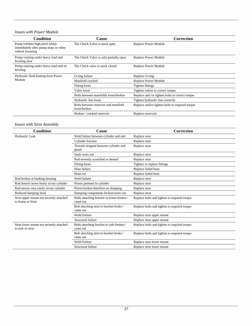
Issues with Power Module
Condition Cause Correction
Pump exhibits high pitch whine
immediately after pump stops or when vehicle lowering
The Check Valve is stuck open Replace Power Module
Pump running under heavy load and
leveling slow The Check Valve is only partially open Replace Power Module
Pump running under heavy load and no
leveling The Check valve is stuck closed Replace Power Module
Hydraulic fluid leaking from Power
Module O-ring failure Replace O-ring
Manifold cracked Replace Power Module
Fitting loose Tighten fittings
Valve loose Tighten valves to correct torque
Bolts between manifolds loose/broken Replace and /or tighten bolts to correct torque
Hydraulic line loose Tighten hydraulic line correctly
Bolts between reservoir and manifold
loose/broken Replace and/or tighten bolts to required torque
Broken / cracked reservoir Replace reservoir
Issues with Strut Assembly
Condition Cause Correction
Hydraulic Leak Weld failure between cylinder and end Replace strut
Cylinder fracture Replace strut
Threads stripped between cylinder and
gland Replace strut
Seals worn out Replace strut
Rod severely scratched or dented Replace strut
Fitting loose Tighten or replace fittings
Hose failure Replace failed hose
Hose cut Replace failed hose
Rod broken at bushing housing Weld failure Replace strut
Rod doesn't move freely in/out cylinder Piston jammed in cylinder Replace strut
Rod moves very easily in/out cylinder Piston broken therefore no damping Replace strut
Reduced damping level Damping components broken/worn out Replace strut
Strut upper mount not securely attached
to frame or Strut
Bolts attaching bracket to frame broken /
came out Replace bolts and tighten to required torque
Bolt attaching strut to bracket broke /
came out Replace bolts and tighten to required torque
Weld Failure Replace strut upper mount
Structural failure Replace strut upper mount
Strut lower mount not securely attached
to axle or strut
Bolts attaching bracket to axle broken /
came out Replace bolts and tighten to required torque
Bolt attaching strut to bracket broke /
came out Replace bolts and tighten to required torque
Weld Failure Replace strut lower mount
Structural failure Replace strut lower mount
38
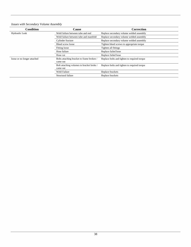
Issues with Secondary Volume Assembly
Condition Cause Correction
Hydraulic Leak Weld failure between tube and end Replace secondary volume welded assembly
Weld failure between tube and manifold Replace secondary volume welded assembly
Cylinder fracture Replace secondary volume welded assembly
Bleed screw loose Tighten bleed screws to appropriate torque
Fitting loose Tighten all fittings
Hose failure Replace failed hose
Hose cut Replace failed hose
loose or no longer attached Bolts attaching bracket to frame broken /
came out Replace bolts and tighten to required torque
Bolt attaching volumes to bracket broke /
came out Replace bolts and tighten to required torque
Weld Failure Replace brackets
Structural failure Replace brackets
39
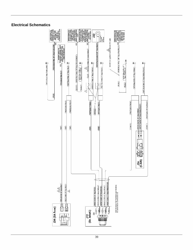
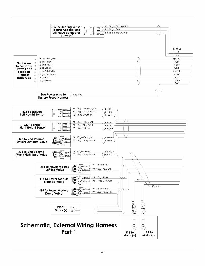
Electrical Schematics
40

41

42
Appendix A: Frame Drilling Locations
Figure A1: Driver side template location for upper strut mount frame drilling.
Figure A2: Passenger side template location for upper strut mount and track rod frame mount frame drilling.

43
Appendix B: Part Number Compatibility – Serial Number Cutoff
Suspension kits S/N: 2001859 and newer have undergone redesign to incorporate larger/wider control arm bushings, see image below.
When ordering replacement parts please make sure to reference the Serial Number on the Driver Side Front Hanger to verify part
compatibility. The following components are not compatible from one Serial Number Vintage to the other after the redesign:
Front Hangers: See Page 11
Axle Seat, LH and RH: See Page 13
Lower Axle Clamp-Cradle: See Page 13
Upper and Lower Control Arms: See Page 14
Height Sensor Linkages: See Page 19
44
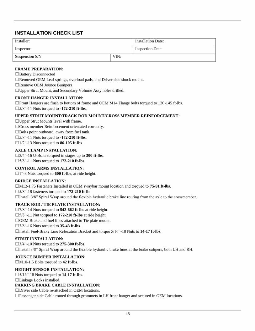
45
INSTALLATION CHECK LIST
Installer: Installation Date:
Inspector: Inspection Date:
Suspension S/N: VIN:
FRAME PREPARATION:
☐Battery Disconnected
☐Removed OEM Leaf springs, overload pads, and Driver side shock mount.
☐Remove OEM Jounce Bumpers
☐Upper Strut Mount, and Secondary Volume Assy holes drilled.
FRONT HANGER INSTALLATION:
☐Front Hangers are flush to bottom of frame and OEM M14 Flange bolts torqued to 120-145 ft-lbs.
☐5/8”-11 Nuts torqued to -172-210 ft-lbs.
UPPER STRUT MOUNT/TRACK ROD MOUNT/CROSS MEMBER REINFORCEMENT:
☐Upper Strut Mounts level with frame.
☐Cross member Reinforcement orientated correctly.
☐Bolts point outboard, away from fuel tank.
☐5/8”-11 Nuts torqued to -172-210 ft-lbs.
☐1/2”-13 Nuts torqued to 86-105 ft-lbs.
AXLE CLAMP INSTALLATION:
☐3/4”-16 U-Bolts torqued in stages up to 300 ft-lbs.
☐5/8”-11 Nuts torqued to 172-210 ft-lbs.
CONTROL ARMS INSTALLATION:
☐1”-8 Nuts torqued to 600 ft-lbs, at ride height.
BRIDGE INSTALLATION:
☐M12-1.75 Fasteners Installed in OEM swaybar mount location and torqued to 75-91 ft-lbs.
☐5/8”-18 fasteners torqued to 172-210 ft-lb.
☐Install 3/8” Spiral Wrap around the flexible hydraulic brake line routing from the axle to the crossmember.
TRACK ROD / TIE PLATE INSTALLATION:
☐7/8”-14 Nuts torqued to 542-662 ft-lbs at ride height.
☐5/8”-11 Nut torqued to 172-210 ft-lbs at ride height.
☐OEM Brake and fuel lines attached to Tie plate mount.
☐3/8”-16 Nuts torqued to 35-43 ft-lbs.
☐Install Fuel-Brake Line Relocation Bracket and torque 5/16”-18 Nuts to 14-17 ft-lbs.
STRUT INSTALLATION:
☐3/4”-10 Nuts torqued to 275-300 ft-lbs.
☐Install 3/8” Spiral Wrap around the flexible hydraulic brake lines at the brake calipers, both LH and RH.
JOUNCE BUMPER INSTALLATION:
☐M10-1.5 Bolts torqued to 42 ft-lbs.
HEIGHT SENSOR INSTALLATION:
☐5/16”-18 Nuts torqued to 14-17 ft-lbs.
☐Linkage Locks installed.
PARKING BRAKE CABLE INSTALLATION:
☐Driver side Cable re-attached in OEM locations.
☐Passenger side Cable routed through grommets in LH front hanger and secured in OEM locations.
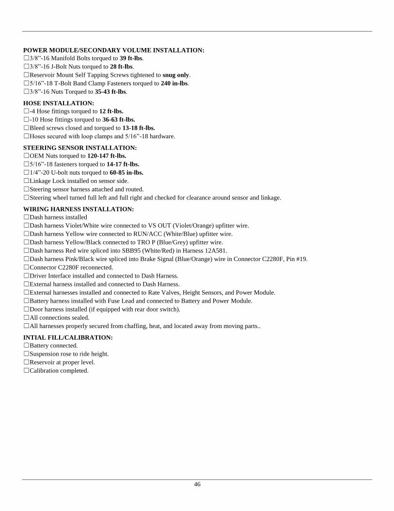
46
POWER MODULE/SECONDARY VOLUME INSTALLATION:
☐3/8”-16 Manifold Bolts torqued to 39 ft-lbs.
☐3/8”-16 J-Bolt Nuts torqued to 28 ft-lbs.
☐Reservoir Mount Self Tapping Screws tightened to snug only.
☐5/16”-18 T-Bolt Band Clamp Fasteners torqued to 240 in-lbs.
☐3/8”-16 Nuts Torqued to 35-43 ft-lbs.
HOSE INSTALLATION:
☐-4 Hose fittings torqued to 12 ft-lbs.
☐-10 Hose fittings torqued to 36-63 ft-lbs.
☐Bleed screws closed and torqued to 13-18 ft-lbs.
☐Hoses secured with loop clamps and 5/16”-18 hardware.
STEERING SENSOR INSTALLATION:
☐OEM Nuts torqued to 120-147 ft-lbs.
☐5/16”-18 fasteners torqued to 14-17 ft-lbs.
☐1/4”-20 U-bolt nuts torqued to 60-85 in-lbs.
☐Linkage Lock installed on sensor side.
☐Steering sensor harness attached and routed.
☐Steering wheel turned full left and full right and checked for clearance around sensor and linkage.
WIRING HARNESS INSTALLATION:
☐Dash harness installed
☐Dash harness Violet/White wire connected to VS OUT (Violet/Orange) upfitter wire.
☐Dash harness Yellow wire connected to RUN/ACC (White/Blue) upfitter wire.
☐Dash harness Yellow/Black connected to TRO P (Blue/Grey) upfitter wire.
☐Dash harness Red wire spliced into SBB95 (White/Red) in Harness 12A581.
☐Dash harness Pink/Black wire spliced into Brake Signal (Blue/Orange) wire in Connector C2280F, Pin #19.
☐Connector C2280F reconnected.
☐Driver Interface installed and connected to Dash Harness.
☐External harness installed and connected to Dash Harness.
☐External harnesses installed and connected to Rate Valves, Height Sensors, and Power Module.
☐Battery harness installed with Fuse Lead and connected to Battery and Power Module.
☐Door harness installed (if equipped with rear door switch).
☐All connections sealed.
☐All harnesses properly secured from chaffing, heat, and located away from moving parts..
INTIAL FILL/CALIBRATION:
☐Battery connected.
☐Suspension rose to ride height.
☐Reservoir at proper level.
☐Calibration completed.