Embed Size (px)
Citation preview

Setup and Configuration of Digi Connect WAN Modem with VR-Link (Vector) IS10014 Issue 1.0 11 November 2010
Nautel Limited 10089 Peggy's Cove Road, Hackett's Cove, NS, Canada B3Z 3J4 T.877 6 nautel (628835) or +1.902.823.2233 F.+1.902.823.3183 [email protected] U.S. customers please contact: Nautel Inc. 201 Target Industrial Circle, Bangor ME 04401 T.877 6 nautel (628835) or +1.207.947.8200 F.+1.207.947.3693 [email protected] e-mail: [email protected] www.nautel.com © Copyright 2010 NAUTEL. All rights reserved.


Setup & Configuration – Digi Connect WAN Modem with VR-Link Page 1 IS10014 Issue 1.0
VR-Link
PC Host
GSM/GPRS Serial Server
GSM/GPRS Serial Server Tbilisi NDB
Cellular Network
PC Host VR-Link GSM/GPRS
Serial ServerGSM/GPRS
Serial Server Tbilisi NDB
Cellular Network
IS10014 Setup and Configuration of Digi Connect WAN Modem with VR-Link (Vector) INFORMATION SHEET
1 INTRODUCTION This document provides setup and configuration information for Digi Connect WAN GSM modems. The GSM modems will enable remote communication to your Vector NDB product across a cellular network in the event that a land line is not available. By connecting a Nautel VR-Link to the GSM modems you will be able to monitor your NDB’s critical parameters, status and event logs. The VR-Link also provides remote control of the NDB. There are two types of configurations or profiles discussed in this procedure – a serial bridge profile and a port forwarding or IP forwarding profile. The type of profile you use depends on how your system is set up.
For example, when communicating directly from a host computer to the NDB across the cellular network you would use a serial bridge profile (see Figure 1). The serial bridge acts as a transparent RS-232 serial link between the computer and the NDB. The serial bridge profile is also used if you have a VR-Link on the host side of the connection. On the other hand if you have a VR-Link at the remote site (i.e., the NDB side), you would use an IP forwarding profile (see Figure 2). (a) Determine which profile best suits your
system and perform the appropriate Setup and Configuration procedure in paragraph 2 (Serial Bridge Profile) or 4 (IP Forwarding Profile), noting the requirements for each profile.
Figure 1: Serial Bridge Profile
Figure 2: IP Forwarding Profile

Page 2 Setup & Configuration – Digi Connect WAN Modem with VR-Link Issue 1.0 IS10014
2 SETUP AND CONFIGURATION – SERIAL BRIDGE PROFILE If you are using the serial bridge profile, perform the following procedure. 2.1 Requirements You will need the following equipment to complete this procedure: • two Digi Connect WAN GSM modems • two SIM cards with fixed (static) IP
addresses provided by your cellular network provider
• two antennas (one for each modem) • two dc power supplies with universal
input (one for each GSM modem) • one 9-pin RS-232 female-to-female
null modem cable. • one 9-pin RS-232 female-to-male null
modem cable. • cross-over Ethernet cable Cat5. • host computer (laptop recommended) • VR-Link
NOTE You can set up either the host side or NDB side of the serial bridge profile first. The key information you need is the mobile IP address of the GSM modem at the other end of the bridge. The mobile IP address must be fixed (i.e., it is always the same). If it is not, you will need to reconfigure the GSM modems each time they are rebooted. 2.2A Setting up the NDB Side 2.2A.1 DIGI CONNECT WAN SETUP (a) Using a 9-pin, female-to-female null
modem serial cable (user provided); connect the Digi Connect WAN’s console port to the NDB’s RS-232 port located on remote interface PWB A3.
(b) Attach the antenna (Nautel Part #
UG60) DC-ANT-DBHG to the modem’s antenna port. Connect your laptop to the Ethernet port of the modem using the blue crossover cable provided with the Digi Connect WAN.
(c) Insert the SIM card into the side of the GSM modem. Make sure it is inserted in the correct orientation and seated properly.
(d) Connect power to the modem using
the 12 V dc supply (Nautel Part # UG59). Do not use the dc supply that is packed with the Digi Connect modem unless using an 115 V ac supply; it is not rated for 240 V ac.
2.2A.2 CONFIGURATION (a) Wait a few seconds for the modem to
boot up. The Digi Connect WAN is factory set with an Ethernet port IP address of 192.168.1.1. Open your web browser (e.g., Internet Explorer) and enter 192.168.1.1 in the address box. This will open the Digi Connect WAN’s Configuration and Management page (see Figure 3) which allows you to change settings and configure the modem for your specific application. The Configuration and Management page is built into the Digi Connect WAN and can be accessed using a direct connection with a crossover cable, across the local area network or across the mobile network.
(b) Under the Configuration heading
select Network. From here you can configure the modem for automatic IP addressing using DHCP or you can change the fixed IP address. Note that if you change the IP address you will need to type the new address into the browser in order to re-open the Configuration and Management page.
NOTE
There is a device discovery utility on the Digi website that will locate any Digi modems connected to the network. This can be used to find the IP address if changed to DHCP or if you forget the address. For this particular setup, the Ethernet port is used only for configuring the modem so the Ethernet port’s IP address can remain as is.

Setup & Configuration – Digi Connect WAN Modem with VR-Link Page 3 IS10014 Issue 1.0
Figure 3: Configuration and Management page
Figure 4: Mobile configuration

Page 4 Setup & Configuration – Digi Connect WAN Modem with VR-Link Issue 1.0 IS10014
(c) Under the Configuration heading select Mobile (see Figure 4). On this page select your service provider, service plan and enter in your username and password if required. Make sure to click Apply whenever any changes are made.
(d) Under the Configuration heading
select Serial Ports. On the page that follows select Port 1. This will bring up the serial port profile selection page (see Figure 5). This page allows you to configure the serial port of the Digi Connect WAN for a particular application. Scroll down and select Serial Bridge then Apply. The modem should reboot. The page that follows (see Figure 6) configures the serial bridge profile to allow you to communicate with the GSM modem at the host site.
(e) Select Initiate serial bridge to the following device and enter the fixed IP address of the GSM modem at the host site. This is the mobile IP address provided by your cellular network provider and not the Ethernet port’s address. Enter 2101 for the TCP Port and select Enable TCP Keep-Alive. De-select Allow other devices to initiate serial bridge. Select Enable secure serial bridge using secure sockets (SLL). Apply changes.
(f) Configure the serial port settings
under Basic Serial Settings (see Figure 7) as follows. You may enter in a description to help identify the serial port later, Apply Changes.
Baud Rate: 19200 Data Bits: 8 Parity: None Stop Bits: 1 Flow Control: None
Figure 5: Serial Port Profile Select

Setup & Configuration – Digi Connect WAN Modem with VR-Link Page 5 IS10014 Issue 1.0
Figure 6: Serial Bridge Configuration
Figure 7: Basic Serial Settings

Page 6 Setup & Configuration – Digi Connect WAN Modem with VR-Link Issue 1.0 IS10014
NOTE It is important that your serial settings match the device you are communicating with (in this case the NDB). If you are not connecting to a Nautel Vector-LP NDB, make sure you use the correct serial settings for that device. Other settings can be configured within the Configuration and Management page depending on the user’s preference but are not needed for correct operation. For help on configuring other settings see the Digi documentation provided on the Digi CD. (g) Configure the TCP settings as follows
(see Figure 8). Under the Advanced Serial Settings scroll down to TCP Settings. Select Send data only under any of the following conditions: and
then select Send after the following number of idle milliseconds. Set this to 100 ms and set Send after the following number of bytes to 1024 bytes. Click Apply.
(h) The Digi Connect WAN modem setup
is complete. Save the configuration by selecting Backup/Restore under the Administration heading and then clicking Backup (see Figure 9), save this to your computer. The backup can be used to restore the GSM modem, if necessary. It can also be used to load onto other Digi GSM modems to avoid repeating the setup procedure. In this case note that the bridge setting IP address and basic serial settings may need to change.
Figure 8: TCP Settings

Setup & Configuration – Digi Connect WAN Modem with VR-Link Page 7 IS10014 Issue 1.0
Figure 9: Backup/Restore

Page 8 Setup & Configuration – Digi Connect WAN Modem with VR-Link Issue 1.0 IS10014
2.2B Setting up the Host Side 2.2B.1 DIGI CONNECT WAN SETUP (a) Using a 9-pin, female-to-male modem
serial cable (user provided); connect the Digi Connect WAN’s console port to the VR-Link’s RS-232 port.
(b) Attach the antenna (Nautel Part #
UG60) DC-ANT-DBHG to the modem’s antenna port. Connect your laptop to the Ethernet port of the modem using the blue crossover cable provided with the Digi Connect WAN.
(c) Insert the SIM card into the side of the
GSM modem. Make sure it is inserted in the correct orientation and seated properly.
Connect power to the modem using the 12 V dc supply (Nautel Part # UG59). Do not use the dc supply that is packed with the Digi Connect modem unless using an 115 V ac supply; it is not rated for 240 V ac.
2.2B.2 CONFIGURATION (a) Repeat paragraph 2.2A.2 for setting
up the host side modem of the bridge, except while setting up the Serial Bridge Settings in step 2.2A.2 (e), de-select Initiate serial bridge to the following device (see Figure 6) and select Allow other devices to initiate serial bridge. Set the TCP port to 2101 and check Enable TCP Keep-Alive.

Setup & Configuration – Digi Connect WAN Modem with VR-Link Page 9 IS10014 Issue 1.0
Figure 10: COMPUTER COM Port Settings
Figure 11: Digi Device Discovery Tool

Page 10 Setup & Configuration – Digi Connect WAN Modem with VR-Link Issue 1.0 IS10014
3 VR-LINK SETUP AND CONFIGURATION There are two ways to set up the VR-Link. Complete either paragraph 3.1 (setup over Ethernet) or 3.2 (setup over serial port). 3.1 VR-Link Setup over Ethernet (a) Download the Netburner discovery
tool at: http://www.netburner.com/support/public_downloads.html (NetBurner IPSetup Tool).
The Netburner discovery tool will
search for the connected VR-Link and display its IP address (see Figure 17). Once the VR-Link is located use the NDK settings to configure the IP address and baud rate.
The IP address can be set to either
DHCP (0.0.0.0) or a static address assigned by the network administrator. A static address is required when connecting directly between the host computer and the VR-Link
Change the baud rate to 19200. Press
“Set” when finished. 3.2 VR-Link Setup over Serial Port (a) An alternative method to setting up
the IP address and baud rate is to use a terminal program.
Connect a 9-pin, female-to-female null
modem serial cable from your computer to Port 0 of the Netburner (internal to the VR-Link, see user manual). Open up HyperTerminal and set up the COM port as follows:
Baud Rate: 115200 Data Bits: 8 Parity: None Stop Bits: 1 Flow Control: None
(b) Connect power to the VR-Link. A message should appear “Waiting 10sec to start ‘A’ to abort”. Type “A” to display the following message:
Netburner SB72EX Monitor V1.0 Jul 2 2004 12:06:03 HELP for help nb>
(c) Type “Setup” and press enter. The
following menu will appear:
MAC address=00-03-F4-02-58-69 1.)IP Address =0.0.0.0 2.)IP Mask =255.255.255.0 3.)IP Gateway =0.0.0.0 4.)TFTP Server=0.0.0.0 5.)TFTP File = 6.)Baudrate =115200 7.)Wait =10 8.)Boot to Application 9.)Exceptions CauseReboot A.)DNS Server =0.0.0.0 B.)Boot Port =0 C.)Switch to Quiet Boot 1-B to change, S to save, X to exit
(d) Item “6” sets the VR-Link’s baud rate. Type “6” and press enter. Now type “19200” and then press enter. The same menu should re-appear with the new baud rate. Finally, type “S” and press enter to save the change. The following message will appear:
Programming Flash from :FFC04000 To:FFC04094 Copying image from: FFC0039C, FFC0043E to:023FFC40 Image copied to start 'A' to abort Configured IP = 0.0.0.0 Configured Mask = 255.255.255.0 MAC Address= 00:03:f4:02:58:69
(e) Disconnect the cable from Port 0 of
the VR-Link and reboot the VR-Link by disconnecting and reconnecting its power.

Setup & Configuration – Digi Connect WAN Modem with VR-Link Page 11 IS10014 Issue 1.0
3.3 VR-Link Connection (a) If you are connecting the VR-Link to a
LAN, note that it is preconfigured for a static IP address of 192.168.1.93. If you are connecting directly to your host computer using a cross-over cable you will need to use a fixed IP address. You can change the VR-Link to DHCP using the same method as in paragraphs 3.1 and 3.2, except set the IP address to 0.0.0.0.
To locate the IP address of the VR-
Link using DHCP, use the Netburner discovery tool at:
http://www.netburner.com/support/public_
downloads.html (NetBurner IPSetup Tool).
(b) You may find that when opening the
web page it will display a message “Not in contact with the device”. This issue may arise due to latency issues between the VR-Link requesting data and the transmitter replying. The result is the VR-Link times out while waiting for a response. This will prevent the VR-Link from establishing contact with the transmitter.
If this appears to be the case, you will see that the “Active” LED on each modem is blinking but the Web Page still shows “Not in contact with the device”.
Log into the VR-Link and select Site
Configuration. Adjust the Serial Timeout interval up as required to ensure the VR-Link establishes communication with the transmitter. A setting of 5 seconds should be sufficient.
NOTE You will notice the amount of time it takes for the VR-Link page to update using the serial bridge profile is considerably more than when connecting using the IP forwarding profile, which is discussed in paragraph 4. This is due to the method that the VR-Link uses to request data from the NDB. The VR-Link requests data from the NDB in many small packets. While the GSM modems are communicating, there will be some latency in each direction of communication. This may be caused by a number of factors, such as; the network or environmental conditions. Therefore each time the VR-Link sends a request for a packet of data, there is a delay before the transmitter receives the request and responds and before the VR-Link receives a reply. Multiplying by the number of data packets requested can result in a significant delay. The end result is that while sending data and controlling the NDB from the host computer takes only about five seconds, the feedback and web page update may take between 45 and 125 seconds. Since with the IP Forwarding Profile the VR-Link is directly connected to the transmitter, this latency does not have the same effect. Initially the web page will take between 45 and 125 seconds before the first update is complete and “Not in contact with the device” is no longer displayed. This may also be longer if the VR-Link first has to download the events log.

Page 12 Setup & Configuration – Digi Connect WAN Modem with VR-Link Issue 1.0 IS10014
4 SETUP AND CONFIGURATION – IP FORWARDING PROFILE If you are using the IP forwarding profile, perform the following procedure. 4.1 Requirements You will need the following equipment to complete this procedure: • two Digi Connect WAN GSM modems • two SIM cards with fixed (static) IP
addresses provided by your cellular network provider
• two antennas (one for each modem) • two dc power supplies with universal
input (one for each GSM modem) • one 9-pin RS-232 female-to-female
modem cable. • two cross-over Ethernet cable Cat5. • host computer (laptop recommended) • Vector NDB transmitter • VR-Link
NOTE When setting up the IP forwarding profiles either the host side or the remote side can be set up first. All IP addresses must be fixed for IP forwarding. The GSM modems are configured to forward to a specific IP address. If the IP address changes, the modems need to be re-configured. 4.2A Setting up the NDB Side 4.2A.1 DIGI CONNECT WAN SETUP (a) Attach the antenna (Nautel Part #
UG60) DC-ANT-DBHG to the modem’s antenna port. Connect your laptop to the Ethernet port of the modem using the blue cross-over cable provided with the Digi Connect WAN.
(b) Insert the SIM card into the side of the
GSM modem. Make sure it is inserted in the correct orientation and seated properly.
(c) Connect power to the modem using
the 12 V dc supply (Nautel Part # UG59). Do not use the dc supply that is packed with the Digi Connect modem unless using an 115 V ac supply; it is not rated for 240 V ac.
4.2A.2 CONFIGURATION (a) Wait a few seconds for the modem to
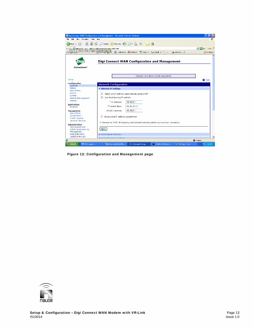
boot up. The Digi Connect WAN is factory set with an Ethernet port IP address of 192.168.1.1. Enter this address in a web browser (e.g., Internet Explorer) to open the Digi Connect WAN’s Configuration and Management page (see Figure 12). This page allows you to change settings and configure the modem for your specific application. The Configuration and Management page is built into the Digi Connect WAN and can be accessed using a direct connection with a cross-over cable, across the local area network or across the mobile network.
(b) Under the Configuration heading
select Network. You do not need to change the IP address. If you change the IP address you will need to type the new address into the browser in order to re-open the Configuration and Management page.
(c) Under the Configuration heading
select Mobile (see Figure 13). In this page select your service provider, service plan and enter in your username and password if required. Make sure to click Apply when any changes are made.
(d) Under the Configuration heading
select Network. Select Network Services Settings (see Figure 14).
• Change the Enable Web Server
(HTTP) TCP Port to 8080. The IP address used to access the Configuration and Management page will also need to change (e.g., from 192.168.1.1 to 192.168.1.1:8080).
NOTE
Normally, HTTP web based pages are set to port 80, but in this case, the VR-Link uses port 80 for its web page, which would cause a conflict between the GSM modem’s Configuration and Management page and the VR-Link.
Setup & Configuration – Digi Connect WAN Modem with VR-Link Page 13 IS10014 Issue 1.0
Figure 12: Configuration and Management page

Page 14 Setup & Configuration – Digi Connect WAN Modem with VR-Link Issue 1.0 IS10014
Figure 13: Mobile Configuration
Figure 14: Network Services Settings

Setup & Configuration – Digi Connect WAN Modem with VR-Link Page 15 IS10014 Issue 1.0
(e) Under the Configuration heading select Network. Select Network Address Translation (NAT) Settings (see Figure 15). From this page you can set up your IP forwarding settings.
• Check Enable IP Forwarding. • Check Enable Network Address
Translation (NAT). • Set or verify NAT Public Interface is
set to mobile0. • In the Forward TCP/UDP/FTP
connections from external networks to the following internal devices: section, enter the following: Enable: Check Protocol: TCP External port: 80 Forward to Internal IP Address:192.168.1.93 Forward to Internal Port: 80 Range Port Count: 1
• Select Add, and then select Apply.
NOTE The Forward to Internal IP Address entered is the IP address of, in this case the VR-Link. This will be set up in paragraph 5. If you use a different address for the VR-Link you will need to change the address here as well. This will be the same when setting up the host side, were the entered IP address will be that of the host computer. (f) The Digi Connect WAN modem setup
is complete. Save the configuration by selecting Backup/Restore under the Administration heading, then clicking on Backup (see Figure 16). The backup can be used to restore the GSM modem, if necessary. It can also be used to load onto other Digi GSM modems to avoid repeating the setup procedure.
Figure 15: Network Address Translation (NAT) Settings

Page 16 Setup & Configuration – Digi Connect WAN Modem with VR-Link Issue 1.0 IS10014
Figure 16: Backup/Restore

Setup & Configuration – Digi Connect WAN Modem with VR-Link Page 17 IS10014 Issue 1.0
Figure 17: NetBurner IPSetup V2.0 4.2B Setting up the Host Side 4.2B.1 DIGI CONNECT WAN SETUP (a) Attach the antenna (Nautel Part #
UG60) DC-ANT-DBHG to the modem’s antenna port. Connect your laptop or host computer to the Ethernet port of the modem using the blue cross-over cable provided with the Digi Connect WAN. You may also connect the Digi Connect WAN to your host computer though a network hub.
(b) Insert the SIM card into the side of the
GSM modem. Make sure it is inserted in the correct orientation and seated properly.
(c) Connect power to the modem using
the 12 V dc supply (Nautel Part # UG59). Do not use the dc supply that is packed with the Digi Connect modem unless using an 115 V ac supply; it is not rated for 240 V ac.
4.2B.2 CONFIGURATION (a) Configure the host side Digi Connect
WAN using the same procedure as in 4.2A.2.
(b) Once you have set up the host side
Digi Connect WAN, go to System Information under the Administration heading in the Configuration and Management page. Select Mobile. Listed here you will find data on the mobile connection such as the mobile IP address. Scroll down until you find the primary and secondary DNS addresses. These numbers will be used when configuring your host computer.

Page 18 Setup & Configuration – Digi Connect WAN Modem with VR-Link Issue 1.0 IS10014
(c) On your computer navigate to the Internet Protocol (TCP/IP) Properties page (see Figure 18) by clicking on Start, Control Panel, and Network Connections. Right click on the Local Area Connection and select Properties in the pop up menu. In the Local Area Connection Properties page scroll down and click on Internet Protocol (TCP/IP) then select Properties.
(d) In the Internet Protocol (TCP/IP)
Properties page select Use the following IP address and configure as follows.
IP address: 192.168.1.2 Subnet mask: 255.255.255.0 Default Gateway: 192.168.1.1 Enter the primary and secondary DNS server addresses obtained above from the Digi Connect WAN. Select OK.
NOTE You can use a different IP address, but remember to enter that IP address when setting up your IP forwarding settings in the Digi Connect WAN. (e) If you haven’t already, connect the
Digi Connect WAN to the host computer using either a cross-over cable or a hub. The host side should now be set up and ready to use.
(f) To access the VR-Link webpage (see
Figure 19), open an internet browser (e.g., Internet Explorer) and enter the mobile IP address of the remote site (e.g., http://172.29.43.74). This is the fixed IP address provided by your cellular network provider.
(g) You can also access the remote Digi
Connect WAN’s Configuration and Management page by entering the remote mobile IP address followed by ‘:8080’ (e.g., http://172.29.43.74:8080)
Figure 18: Internet Protocol (TCP/IP) Properties

Setup & Configuration – Digi Connect WAN Modem with VR-Link Page 19 IS10014 Issue 1.0
Figure 19: VR-Link webpage 5 VR-LINK SETUP AND CONFIGURATION (a) Connect the VR-Link’s RS-232 port to
the NDB’s remote interface PWB A3 using a 9-pin, female-to-male modem serial cable.
(b) Connect your laptop to the VR-Link’s
Ethernet port using a cross-over cable and apply power to the VR-Link.
(c) The VR-Link is pre-configured for a
static IP address of 192.168.1.93. You may change the IP address by following paragraphs 3.1 or 3.2 on page 10.
(d) Set the NDK settings as follows. IP: 192.168.1.93 Mask: 255.255.255.0 Gateway: 192.168.1.1 (same as Digi Connect WAN’s default Gateway) DNS: 192.168.1.1 Ensure the baud rate is set to 19200.

Page 20 Setup & Configuration – Digi Connect WAN Modem with VR-Link Issue 1.0 IS10014
6 TROUBLESHOOTING If the GSM modems are not communicating properly, check the following: 6.1 Connections Check for loose cables and connections. 6.2 Signal Strength Ensure that the Digi Connect WAN is communicating with the remote network and has a strong signal. Check this by looking at the top of the Digi Connect WAN. Signal strength should show at least two LEDs turned green. If not, try moving the antenna to a new location to improve the signal. The green Link LED should also be on. If not, check the mobile settings (such as the service provider) under Configuration, Mobile in the Configuration and Management page. Also check that the SIM card is installed correctly. The orange Active LED will flash when data is being transmitted. 6.3 IP Address Check all IP addresses. For serial bridge profiles ensure that the IP address in the Serial Bridge Settings is the mobile address of the GSM modem at the other site.
For IP forwarding profiles ensure that the IP address entered in the Network Address Translation (NAT) Settings is that of the device to which you are connecting (i.e., the VR-Link or host computer). Also, make sure the default gateways are the same for both the Digi Connect WAN and the device to which you are connecting. 6.4 Serial Settings Make sure the serial settings are the same when two devices are connected to each other. For example the NDB connected to the GSM modem or VR-Link at the remote site or the GSM modem connected the host computer or VR-Link at the host site. In all cases the serial settings should be set as follows: Baud Rate: 19200 Data Bits: 8 Parity: None Stop Bits: 1 Flow Control: None 6.5 Reboot Try rebooting the Digi Connect WAN by selecting Reboot under the Administration heading in the Configuration and Management page. Do this for both the host and remote modems.


![Nautel Offshore NDB Presentation Dec2014€¦ · Microsoft PowerPoint - Nautel Offshore NDB Presentation Dec2014 [Compatibility Mode] Author: Gary Created Date: 5/20/2015 12:31:03](https://img.pdfslide.us/doc/110x75/60004fef3f1440460250c064/nautel-offshore-ndb-presentation-dec2014-microsoft-powerpoint-nautel-offshore.jpg)