Embed Size (px)
Citation preview

Disclosure to Promote the Right To Information
Whereas the Parliament of India has set out to provide a practical regime of right to information for citizens to secure access to information under the control of public authorities, in order to promote transparency and accountability in the working of every public authority, and whereas the attached publication of the Bureau of Indian Standards is of particular interest to the public, particularly disadvantaged communities and those engaged in the pursuit of education and knowledge, the attached public safety standard is made available to promote the timely dissemination of this information in an accurate manner to the public.
इंटरनेट मानक
“!ान $ एक न' भारत का +नम-ण”Satyanarayan Gangaram Pitroda
“Invent a New India Using Knowledge”
“प0रा1 को छोड न' 5 तरफ”Jawaharlal Nehru
“Step Out From the Old to the New”
“जान1 का अ+धकार, जी1 का अ+धकार”Mazdoor Kisan Shakti Sangathan
“The Right to Information, The Right to Live”
“!ान एक ऐसा खजाना > जो कभी च0राया नहB जा सकता है”Bhartṛhari—Nītiśatakam
“Knowledge is such a treasure which cannot be stolen”
“Invent a New India Using Knowledge”
है”ह”ह
IS 7718 (1991): Recommendations for inspection, testing andmaintenance of fixed wheel and slide gates [WRD 12:Hydraulic Gates and Valves]

IS 7718 : 1991
RECOMMENDATIONSFORINSPECTION, TESTINGANDMAINTENANCEOFFIXED
WHEELANDSLIDEGATE
( First Revision )
UDC 621’833’004’58
@ BIS 1991
BUREAU OF INDIAN STANDARDS k MANAK BHAVAN, 9 BAHADUR SHAH ZAFAR MARG
NEW DELHI 110002
April 1991 _I’
Price Group 4
Hydraulic Gates and Valves Sectional Committee, RVD 12
FOREWORD
This Indian Standard was the Hydraulic Gates and Division Council.
adopted by the Bureau of Indian Standards, after the draft finalized by Valves Sectional Committee had been approved by the River Valley
published by the Indian Standards Institution in three parts. Part I, ._ _ _ ” _- This Indian Standard was published in 1975, deals with inspection, testing and assembly at manutacturmg stage. Part 11, published in 1978, deals with inspection and testing at the time of erection and Part III published in 1975, deals with inspection, testing and maintenance after erection.
This standard is being published merging all the three parts covering inspection and testing to be carried out during manufacture, erection and periodical maintenance of these gates.
Gates provided for controlling water discharges for flood control, water supply, irrigation etc. are required to be manufactured, erected and maintained properly to get the best results and maxi- mum utility of water and to get the designed life of the gate itself.
For the purpose of deciding whether a particular requirement of this standard is complied with, the final value, observed or calculated, expressing the result of a test or analysis, shall be rounded off in accordance with IS 2 : 1960 ‘Rules for rounding off numerical values (revised)‘. The number of significant places retained in the rounded off value should be the same as that of the specified value in this standard.
Indian Standard
RECOMMENDATIONS FOR
IS 7718 : 1991
INSPECTION, TESTING AND MAINTENANCE OF FIXED
WHEEL AND SLIDE GATE
( First Revision ) 1 SCOPE
1.1 This standard lays down the recommenda- tions for inspection, testing and maintenance of fixed wheel and slide gates. ( It does not cover hoists, controls, stem rods, wire ropes, etc. >
2 REFERENCES
2.1bThe following Indian Standards are the necessary adjuncts to this standard:
IS No.
1187 : 1967
2339 : 1963
2825 :.1969
7318 ( Part 1 ) : 1974
Title
Shuttles for sacking looms ( superseded by IS : 1186 )
Aluminium paint for general purposes in dual container
Code for unfired pressure vessels
Approval tests for welders when welding procedure approval is not required: Fe;; 1 Fusion welding of
3 INSPECTIONS
3.1 Inspection during manufacturing stage is to be carried out in respect of the following.
Pf 3.1.1 Materials
All materials and components supplied by the manufacturer shall conform to the requirements of the latest relevant Indian Standard. In the absence of the Indian Standard for any material other specifications, mutually agreed to between the purchaser and the supplier, may be used. For important components, manufacturer’s test certificates shall be furnished.
3.1.2 Castings
a) All castings shall conform to the relevant Indian Standard.
b) If the defects are within aqeptable limits as per the relevant Indian Standard, repairing of castings can be allowed without impairing the strength of machinability.
c) Visual examination shall be done to ascertain the general soundness of the castings and, if required, these may be subjected to non-destructive tests.
3.1.3 Forgings
a) All forgings shall conform to the relevant Indian Standards.
b) All forgings shall be suitably heat-treated, whenever deemed essential.
3.1.4 Welding
a) All weldings shall conform to the relevant Indian Standards.
b) Qualified welders, complying with IS 7318 (Part 1) : 1974, shall be employed
cl
for the welding work. _ -
Visual examinations shall be carried out of all welded joints to ensure that welding is free from the following:
9
ii)
iii)
Undercuts in the parent metals;
Sponginess and porosity in the welded metals;
iv) Non-uniform width of the fillet joints:
Cracks on the surfaces of the joints or parent metals located in the heated zone of the joint;
v) Misalignment and distortion of the welded member; and
vi) Irregular reinforcing beads of welds.
d) Defective welds shall be removed and . redone.
%.-_T * e) The welds which seen questionable, shall
be checked by the manufacturer, using nondestructive testing methods to ensure the soundness of the weld.
f) 10 percent of butt welds on major stress carrying members like gate girders, unsupported butt joints on skin shall be examined by radiographic tests like (X-ray, Gamma ray, etc. ). 50 percent of the remaining butt joints shall be examined by any nondestructive tests namely ultrasonic tests, magnetic particle tests, etc.
g) If necessary, any component may be stress relieved according to the procedure laid down in IS 2825 : 1969.
3.1.5 Manufacturing Tolerances
The gates and the embedded parts shall be manufactured to such an accuracy and tolerances
.
1
Is 7718 : 1991
as are required for efficient operation o-f the gates. Unless otherwise specified, the tolerances given in a, b and c may be used as a general guide.
a) Embedded Parts
i) Deviation of any point on the face of the seal seats or wheel track from a 2 metre machined straight edge held against it shall not exceed ,0’5 mm. However, overall deviation for the entire length shall not be more than 1 mm.
ii) Deviation from straightness of the guide track shall not be more than 2 mm in 2 metre length and 3 mm for the entire length.
iii) Variation in the distance between the face of the seal seat and the face of its respective wheel track shall not exceed 1 mm.
iv) The offset or gap at any adjoining field joints between seal seats, wheel tracks and guide tracks shall not be more than 0’5 mm. The gap at the joint shall be seal welded and ground smooth.
v) The rounding off and clamping of seal seats required shall be checked.
b) Fixed Wheel Gates
i)
ii)
These gates shall be so assembled that when a machined straight edge is held against all the wheels on either side, in neutral position, it shall not be possible to insert a feeler gauge thicker than 1’5 mm between any of the wheels and the straight edge.
The distance between the side guide shoe or guide roller on one side of the gate and the corresponding @ide shoe or guide roller on the other&de shall not differ from the dimension shown in the drawing by more than 1’5 mm.
c) Slide Gates
i)
ii)
The gate and the components shall be so manufactured that on assembly, the side and top seal bases coincide on the same plane within the tolerance as given below:
When a machined straight edge is held against the seal bases, it shall not be possible to insert a 0’2 mm feeler gauge between the seal base and straight edge anywhere. li
After fixing metallic seals their faces shall be tested to ensure that these are in a common plane within the tolerance given below:
When a machined straight edge is held against the metallic seal faces, it shall
iii)
not be possible to insert a 0’2 mm feeler gauge between the seal face and straight edge at any point.
The distance between the side guide shoes or guide rollers on either side of the gate shall not exceed the dimension shown in the drawing by more than 1’5 mm.
4 SHOP ASSEMBLY AND TESTING
4.1 Gate shall be assembled, complete with wheels and guides, either in horizontal or vertical position for proper alignment and inspection.
4.2 Side guide shoes or guide rollers may be shimmed, if necessary, to maintain the required tolerances.
4.3 All the wheels of the gate shall be rotated a number of times to ensure their free movement.
4.4 If ballast is provided, it should be ensured that it is placed in correct position and secured to avoid dislodging during operation of the gate.
4.5 The marking and match marking on the components shall be made before the final despatch of the components.
5 PAINTING
5.1 Painting shall be done according to the requirement of the purchaser and the application procedure shall be as recommended by the paint manufacturer.
5.2 Prior to painting, proper surface prepara- tion should be ensured.
5.3 The painting work done shall be checked for the required specifications regardiug quality of paints, dry film thickness etc.
6 INSPECTION DURING ERECTION WORK IS TO BE CARRIED OUT AT THE FOL&QWIpG STAGES
6.1 General Inspection
6.1.1 It should be ascertained that the gate parts received at site have been manufactured accord- ing to the design and have necessary match markings made at shop. It shall be ensured that all exposed surfaces of the embedded parts have been protected by painting, greasing etc. The surface of the embedded parts in contact with concrete should be free from grease, paint etc. for better bonding with the concrete. A coating of cement wash may be given, if necessary.
6.1.2 Any difference in the. blockouts or critical dimensions shall be corrected before erection. The critical dimensions as mentioned in Fig. 1 should be checked with reference to the drawings during erection and corrected, if required.
2
IS 7718 : 1991
6.1.3 The reference axis lines, centres of openings and levels having relations to completed civil structure shall be established on the site so as to ensure erection at proper locations.
6.1.4 It shall be ensured that all the components of hoisting assemblies, such as motor, reduction gear assembly, wire rope, ‘control panels, etc. are received without any damage. Care shall be taken for proper storage and handling of the components.
6.2 Inspection of Blockouts
Concreting behind the gate groove may be done in one or two stages. If done in two stages, it should be ensured that adequate blockouts are kept for accommodating the gate parts as manufactured both with respect to dimensions and anchorage provision according to the design. Ensure that the requisite dowel bars of adequate length are left out in the blockouts. The entire blockout should be left roughened properly for further concreting to give necessary bond to the second stage concreting.
6.3 Inspection of Embedded Parts
6.3.1 It should be ensured that the sill beam is correctly positioned, both in level and location. All the nuts and bolts of anchorages of the sill beam should be tightened so as to prevent dislocation during and after concreting.
6.3.2 The embedded parts, namely, track beam, guides, seal seats, gate groove lining etc shall be checked when all these parts are in their final position, at least up to double the gate height, in one operation. The check should be carried out both with respect to location and levels with respect to the sill beam already established in position. Each part should be checke:d first individually and thereafter relatively -wJth the other parts. It should be ensured that ‘manu- facturing tolerances, as prescribed, are con- sidered while erecting these parts and even after accounting for these tolerances, the erection work is carried out according to the design provisions.
6.3.3 The track beam and seal seats shall be in true alignment. The alignment can be checked by means of a fine plumb bob and feeler gauge, preferably at 300 mm intervals from bottom to top side of the gate opening. Alternatively, diagonal checking or any other satisfactory method can be adopted for checking the alignments.
'i
6.3.4 After checking the track beams and seal seats on both sides it shall be ensurea that they are in terms of their respective planes. It should be checked that top seal seat, wherever provided, shall also be in the required plane.
6.3.5 Guides and counter guides, if provided, should be checked for exact locatidn and true
alignment, first individually and then also relatively.
6.3.6 Groove liners and corner protection angles, when provided, should bs checked for true location and true alignment.
6.3.7 The following salient dimensions shall be checked at intervals of 300 mm from the bottom to double the gate height. ( Ref. Fig. 1 ):
a) b)
Centre to centre distance of track beams,
Centre to centre distance of side seal seats,
4 4
Face to face distance of guides,
Face of track beam to face of side seal ’ seat,
e) Face to track beam to centre line of guide, and
f) Vertical distance between sill and the centre line of top seal seat.
NOTES
1 Use of a suitable template for checking (d) and (e) above is recommended to maintain correspond- ing portions of vertical embedded parts from sill level up to the top of embedded parts. 2 For the portions falling above the level corres- ponding to double the gate height, the checking interval may be increased to one metre.
3 In case a top seal is provided, the dimensions between the face of the track beam and the face of the top seal seat should also be checked.
6.3.8 Eccentricity or some such arrangement, if provided to a gate for its fina adjustment in the groove, shall not be accounted for while erecting embedded parts.
6.3.9 Anchorages, should bz fastened or welded rigidly, after final adjustment of thn embedded parts, so as to prevent dislocation of the parts while pouring second stage concrete.
6.3.10 The gate groove concreting shall be done only after-satisfying all the above requirements, togethe’r with generating and securing proper records thereof. Randomised recheck ,of align- ment of the embedded parts shall bs done after concreting.
6.3.11 It shall be ensured that there is no step at the joint while extending th: embsdded parts.
6.3.12 Second stage concrete surfaces must be smooth and properly matched with the surface of the embedded parts and of th? first stage concrete design profile, so as to avoid any future cavitation. For high head gates, special care shall be taken for matching the concrete surfaces with the embEdded parts wherever the free stream flow velocity is likely to exceed 30 metres per second.
6.4 Inspection of Gate
6.4.1 The gate which is reeeived on sita, after having it duly inspected in tht: workshop, should
3
IS 7718 : 1991
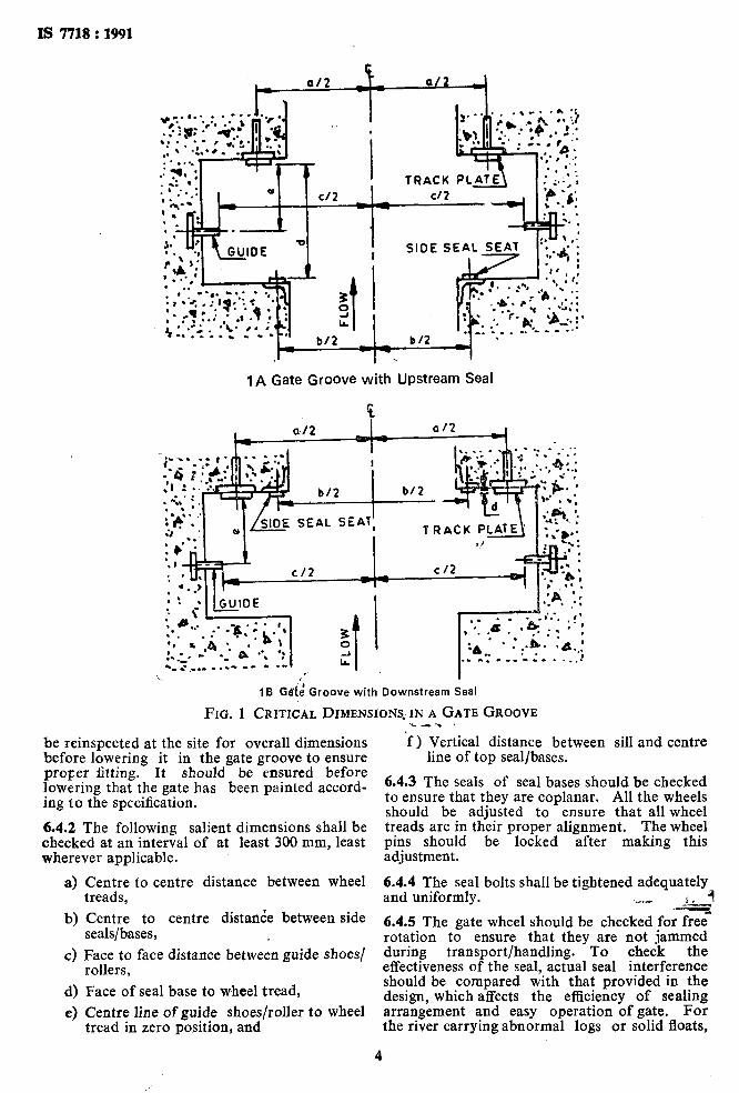
IA Gate Groove with Upstream Seal
IB G&d Groove with Downstream Seal
FIG. 1 CRITICAL DIMENSIONS. IN A GATE GROOVE
be reinspected at the site for overall dimensions before lowering it in the gate groove to ensure proper fitting. It should be ensured before lowering that the gate has been painted accord- ing to the specification.
6.4.2 The following salient dimensions shall be checked at an interval of at least 300 mm, least wherever applicable.
a) Centre to centre distance between wheel treads,
b) Centre to centre distatide between side seals/bases,
c) F’ic,zr’,” face distance between guide shoes/ 7
d) Face of seal base to wheel tread,
e) Centre line of guide shoes/roller to wheel tread in zero position, and
4
'f ) Vertical distance between sill and centre line of top seal/bases.
6.4.3 The seals of seal bases should be checked to ensure that they are coplanar. All the wheels should be adjusted to ensure that all wheel treads are in their proper alignment. The wheel pins should be locked after making this adjustment.
6.4.4 The seal bolts shall be tightened adequately and uniformly. *r. _ 7 .L&, -_ 6.4.5 The gate wheel should be checked for free rotation to ensure that they are not jammed during transport/handling. To check the effectiveness of the seal, actual seal interference should be compared with that provided in the design, which affects the efficiency of sealing arrangement and easy operation of gate. For the river carrying abnormal logs or solid floats,
adequate protection should be devised to safeguard the life of the seals. This can be done either by operational parameters of gates or by providing screening device before the gate.
6.4.6 In case of counterweighted gates or gates with ballast it should be ensured that the weights have been added and secured properly at correct place. This is very important consideration to achieve the correct seating pressure.
7 INSPECTION OF COMPLETE GATE INSTALLATION
7.1 It sho,uld be ensured that the installation of the various parts of the gate and hoisting arrangement conforms to specified location and alignment, particularly with respect to correct positioning and attachment of rope/stem of the gate as well as hoist.
7.2 It should be ensured that the gate groove, sill and the embedded parts are thoroughly cleaned
and no foreign material is present in the groove. Before lowering the gate it is advisable to check the gate passage, either with the help of template representing the cross section of the gate in plan or by any other means, to ensure that the gate groove is free from any obstruction.
7.3 During inspection it may be ensured that there is an adequate space to carry out maintenance, replacement or repairs on gates or parts like wheels, rubber seals etc.
8 TESTING
8.1 The gate should be tested preferably in a dry condition with the hoist duly connected for its smooth working. The gate should be moved up down in the groove with no obstruction and no undue efforts required for its operation. If the gate cannot slide down of its own weight or if it is found to be going tight anywhere ,reasons should be investigated and remedied @stead of forcing the gate down. - c-l
8.2 The testing of the gate seals in dry conditions should be done by suitable means, such as by viewing the contact surfaces against a light source. Ensure that the seal rides smoothly over the seal seat at the time of its approach to the latter during the gate operation. Seal seat shall be cleaned before the trial operation.
8.3 In case of rubber seals, water should be initially poured over the seals so that there is no dry friction of the seals. In case of metal to metal contact, oil or grease is to be used. No grease or lubricant is to be used at rubber seals. i
8.4 There should be no noise due to friction or otherwise, nor any signs of excessive friction. The performance shall be free of jerks or any dug-in at any position. There shall be no dangling of the gate or twist in the rubber seals. The top seals should not leave their plane and the rubber seals should not be overpressed.
IS 7718 : 1991
8.5 The test against leakage shall be carried out as follows. The gate is to first rest on the sill beam, that is, the closed position. The leakage test can be taken in this position by using suitable pump, with necessary arrangements of jetting water at 1’5 times the designed pressure on seal position from bottom to top. Particularly all corner joints and other joints, if any, are to be tested to ensure perfect working of the gate. Allowable leakage is from 5-15 litres/metre length of the seal per minute.
8.6 All the tests indicated under 8.1 to 8.5 should be, wherever possible, also performed with water standingat the site to the design head.
8.7 When the gate is operated under standing water, it is to be uniformly ensured that there are no vibrations of the gate or of the civil structure at any of the gate openings.
8.8 Bypass arrangement made for the water should be checked to ensure the proper working of the arrangement. Bypass arrangement shall be provided with an additional emergency valve as a safety measure.
8.9 Air vents, when provided, are to be tested for their choke free performance.
9 PERIODIC INSPECTION AFTER ERECTION
9.1 In order to detect normal wear and tear defects, if any, periodical inspection of the installed gates shall be carried out. Direct visual inspection of these gates shall be done as and when necessary but at least twice a year corresponding to the period when upstream water level is at its highest and lowest level. In case of inaccessible parts, inspection may be necessary through diverse.
9.2 Inspection shall be done for both through the following:
a) Embedded parts, and
bj’-Ci%?e leaf and components.
9.2.1 Inspection of Embedded Parts
All parts, either rigidly fixed in the concrete or partly exposed, shall be subjected to the periodical inspection. This covers sill beam, seal seats, track path, guide path, liners, etc.
All the debris and blockage at and over these parts shall be cleared. Any peculiar formation or deposition, over the embedded parts should carefully monitored. Photographic records may be maintained, if useful.
9.2.1.1 Due to constant use and various known and unknown hydraulic phenomena seal seat, sill beams, track paths etc., get pitted. Eating of the metal of seal seat, if any, should be com- pared with the previous record, variation damages excessive sealing, uneven surfaces, stepping, and should be carefully checked pre- ferably by using magnifying glass.
5
-
IS 7718:1991
9.2.1.2 Due to wear and tear, surfaces may become uneven and may have indentations, for example, roller marks over the track paths. The embedded parts should be in their alignment. Readings of alignments should be taken at intervals of at least 60 cm. Some fixed point may be used for taking readings at every inspection to determine comparative wear and tear.
9.2.1.3 The following salient dimensions should be periodically checked at longitudinal intervals, not less than 300 mm for conformity as designed:
a) Centre to centre distance between the track plates,
b) Centre to centre distance between the side seals,
c) Face to face distance between the guides,
d) Face of seal seat to face of track path,
e) Centre of guide path to face of track path, and
f) Vertical distance between sill and centre line of top seal seat.
9.2.1.4, The maintenance of conformity in the dimensions mentioned in 9.2.1.3 shall be equally obtained for the gate leaves as well.
9.2.1.5 All nuts, bolts and screws shall be periodically checked for wear, tear and tightness. Countersunk screws and bolts shall be checked for holding on to their proper positions. All welds shall be checked for cracks and other defects, if any.
9.2.1.6 The entire gate shot shall be checked thoroughly so as not to have any obstructions for travel of the gate.
9.2.1.7 In case of sliding gates all sealing metallic surfaces shall be inspected with;utmost care. - C-e
9.2.2 Inspection of Gate Leaf and Components
9.2.2.1 A debris and sealing should be removed from the gate leaf. Peculiar formations, if any, on the leaf should be carefully stripped off the scales. Photographic records should be kept, if necessary. The skin plate and other components should be tapped lightly by hammer to examine soundness.
9.2.2.2 The dry side of the skin plate should be checked for the welds, joints of horizontal and vertical members and any drain holes for the horizontal members.
9.2.2.3 Hoisting connection on the gate leaf should be checked for shearing i or punching effect and wear and tear.
9.2.2.4 Alignment of seals should be precision checked by means of a thread and feeler gauge. All corner joints should be checked for any cracks. In case of musical note rubber seals, twists, overlapping bulb flatness, deformation,
etc. should be checked. There should not be any undesirable material into the rubber seal and in between the rubber seal and the skin plate. Retractable seals should be checked for their effectiveness. Use of oil or grease over rubber seals should be avoided. Cladded rubber seals should be inspected for proper adhesion between cladding and the rubber. All the nuts and bolts, fixing rubber seals to the gate, should be checked. In case of metallic seals, thickness and camber, if any, should be checked. Lubricating system if provided, should be checked for free flow of lubricant.
9.2.2.5 Alignment of rollers should be checked and deviation of alignment should be noted. Each roller should be checked for maladjustment of the pin or any other defect. It should be rotated a number of times to ensure its free rotation. The bearing should be checked for proper functioning.
9.2.2.6 The following salient dimensions should be periodically checked at longitudinal intervals, not less than 300 mm for conformity as designed:
a)
b)
4
d)
4
Centre to centre distance between the rollers of the fixed wheel gate,
Centre to centre distance between the side seals,
Face to face distance between the face of guide shoes or guide rollers,
Face of the rollers to face of the seal base,
Distance between the wheel face and the centre of the guide shoe or guide roller in case of fixed wheel gate and distance between the face of slide plate and centre of the guide shoe or guide rollers for slide gates.
9.2.2.7 The maintenance of conformity in the dimensions mentioned 9.2.2.6 shall be equally obtained for the embedded parts.
9.2.2.&W- the nuts, bolts and screws shall be periodically checked for wear, tear and tightness. Countersunk screws and bolts shall be checked for holding on to their proper posi- tions. All welds shall be checked for cracks and other defects, if any.
10 TESTING
10.1 The gate should be tested for its smooth travel throughout in the groove, both up and down, without appreciable sway, anywhere. All rollers shall always be in contact with the track surface during the entire travel.
lo,.2 The gate shall cot be subjected to undue pressure; nor should any extra effort be needed to operate the gate, under no load condition. The operation should be trouble free and without rattle. If it is noticed that extra efforts are needed it should be measured by torque meter with suitable arrangements.
6
IS 7718 : 1991
lo.3 On load ( i.e. when there is water ) there should be ro undue vibrations in the gate and the structure. In case vibrations are noticed during the operation of the gate, the reason thereof should be investigated. Until remedial measures are taken, gate shall not be kept in the position at which vibrations are noticed.
10.4 The gate should be watched against any leakage in its closed position at least once under maximum head condition available in a year.
11 MAINTENANCE OF GATE
11.1 Any weld that might have become defective should be chipped out and remade. Damaged nuts, bolts, rivets, screws etc should be replaced without delay.
11.2 The gate slot and platform should be cleaned periodically. Scales formed over the embedded parts should be removed. All bottom corners should be cleaned and accumulations, removed. Anchorages and concrete around anchorages should be checked for any develop- ing cracks or slackness, etc, and repair should be attended to immediately.
11.3 The gate leaf should be thoroughly cleaned and repainted, as and when necessary, according to the procedure recommended by the paint manufacturer.
11.4 Rubber seals should be ground, if required to keep it in one alignment. All nuts and bolts fixing the seal to the gate should be tightened uniformly. Seals, when damaged or found leaking excessively, should be adjusted, repaired or replaced as considered necessary.
11.5 Gate roller bearings and guide roller bushes should be properly lubricated.
11.5.1 Whenever necessary these should be opened for rectifications of defects; and after cleaning and lubrication, should be ‘refitted.
These may be replaced if repairs are not possible.
11.6 Hoisting connection on the gate leaf should be lubricated where necessary and defects if any should be rectified.
11.7 All nuts, bolts, check nuts and cotter pins of the lifting devices should be checked periodically.
13.8 Where filling valves are provided as part of the gate structure, all the nuts, bolts, checknuts etc should be checked periodically. It shall also be ensured that the filling valves completely shut-off the passage of water when the load is removed. To ensure the springs and other components shall be periodically checked and replaced if necessary.
11.9 All components should be greased and lubricated according to coda1 provisions. Recommended and approved oils and grease only should be used.
11.10 Appropriate remedial measures should be taken so that the salient dimensions mentioned in 9.2.1.2 and 9.2.2.6 and alignment of com- ponents mentioned in 9.2.1 are set right. Appropriate repairs should also be carried out wherever excessive pitting and other surface damages are noted.
11.11 The roller assembly should be adjusted by the eccentricity arrangement to ensure that all the rollers rest uniformly on the track plates, particularly in the closed position of the gate.
11.12 Maintenance charts showing the components of gates and hoists and their periodically undertaken checking maintenance measure should be displayed in the control room set up with respect to the gates for timely implementation. A register showing the time and the date of operation, the amount of opening, discharge, etc should be maintained.
7
Standard Mark <I -e-l
The use of the Standard Mark is governed by *the-provisions of the Bureau of Indian Standards Act, 2986 and the Rules and Regulations made thereunder. The Standard Mark on products covered by an Indian Standard conveys the assurance that they have been produced to comply with the requirements of that standard under a well defined system of inspection, testing and quality control which is devised and supervised by BIS and operated by the pro- ducer. Standard marked products are also continuously checked by BIS for conformity to that standard as a further safeguard. Details of conditions under which a licence for the use of the Standard Mark may be granted to manufacturers or producers may be obtained from the Bureau of Indian Standards.
Bweau of Indian Standards
BIS is a statutory institution established under the Bureau ofZndiun Stundardp Act, 1986 to promote harmonious development of the activities of standardization, marking and quality certification of goods and attending to connected matters in the country.
Copyright
BIS has the copyright of all its publications. No part’ of these publications may be reproduced in any form without the prior permission in writing of BIS. This does not preclude the free use, in the course of implementing the standard, of necessary details, such as symbols and sizes, type or grade designations. Enquiries relating to copyright be addressed to the Director ( Publication ), BIS.
Revision of Indian Standards
Indian Standards are reviewed p$iodically and revised, when necessary and amendments, if any, are issued from time to time. Users of Indian Standards should ascertain that they are in possession of the latest amendments or edition.. Comments on this Indian Standard may be sent to BIS giving the following reference :
Dot : NoPRVD 12 (. 4665 )
Amendments Issued Since Publication
Amend No. Date of Issue Text Affected
:. .’
-.
BUREAU OF INDIAN STANDARDS
Headquarters :
Manak Bhavan, 9 Bahadur Shah’Zafar Marg, New Delhi 1 loo02
Telephones : 331 01 31, 331 13 75 . e’
.’ - r*
Regional Offices : :
Central : Manak Bhavan, 9 Bahadur Shah Zafar Marg- - w *
NEW DELHI 110002
Eastern : I/14 C.I.T. Scheme VII M, V.I.P. Road, Maniktola
CALCUTTA 700054
Telegrams : Manaksanstha ( Common to all Offices )
Telephone
331 01 31 331 13 7s
37 86 62
Northern : SC0 445-446, Sector 35-C, CHANDIGARH 160036 53 38 43
Southern : C.I.T. Campus, IV Cross Road, MADRAS 600113 41 29 16
Western : Manakalaya, E9 MID?, Marol, Andheri ( East ) BOMBAY 400093 ’ 6 32 92 95
Branches : AHMADABAD. BANGALORE. BHOPAL. BHUBANESHWAR. COIMBATORE. FARIDABAD. GHAZIABAD. GUWAHATI. HYDERABAD. JAIPUR. KANPUR. PATNA. THIRUVANANTHAPURAM.