Embed Size (px)
Citation preview

Disclosure to Promote the Right To Information
Whereas the Parliament of India has set out to provide a practical regime of right to information for citizens to secure access to information under the control of public authorities, in order to promote transparency and accountability in the working of every public authority, and whereas the attached publication of the Bureau of Indian Standards is of particular interest to the public, particularly disadvantaged communities and those engaged in the pursuit of education and knowledge, the attached public safety standard is made available to promote the timely dissemination of this information in an accurate manner to the public.
इंटरनेट मानक
“!ान $ एक न' भारत का +नम-ण”Satyanarayan Gangaram Pitroda
“Invent a New India Using Knowledge”
“प0रा1 को छोड न' 5 तरफ”Jawaharlal Nehru
“Step Out From the Old to the New”
“जान1 का अ+धकार, जी1 का अ+धकार”Mazdoor Kisan Shakti Sangathan
“The Right to Information, The Right to Live”
“!ान एक ऐसा खजाना > जो कभी च0राया नहB जा सकता है”Bhartṛhari—Nītiśatakam
“Knowledge is such a treasure which cannot be stolen”
“Invent a New India Using Knowledge”
है”ह”ह
IS 7114 (1973): Criteria for hydraulic design of crossregulators for canals [WRD 13: Canals and Cross DrainageWorks]


Indian Standard
CRITERiA FOR HYDRAULIC DESIGN OF CROSS
! 1
REGULATORS FOR CANALS
(Fourth Reprint AUGUST 1993)
UDC 627,845
43 Copyright 1974
BUREAU OF INDIAN STANDARDS MANAK BHAVAN, 9 BAHADUR SHAH ZAFAR MARG
NEW DELHI 110002
Gr 3 June 1974
15:7114-1973
Indian Standard CRITERIA FOR
HYDRAULIC Di3STGN OF CROSS REGULATORS FOR CANALS
Canals and Canal Linings Sectional Committee, BDC 57
Chairman Representing
SHRI K.V. SREENIVASARAO Central Water & Power Commission, New Delhi
Members
SHRI M. M. ANANI)
SHRI S. S. SAHI ( Alternate) SHRI K. BASANNA
Irrigation & Power Department, Government of Punjab
CHIEF ENGINEER ( IRRIGATION ) Public Works Department, Government of Mysore Public Works Department, Government of Tamil
Nadu Sam K. SUNDARAM (Alternate )
SHRI 0. P. DATTA DEPUTY SURVEYOR GENERAL
Beas Designs Organization, Nangal Township Survey of India, Dehra Dun
MAJ S. N. DIMRI (Alternate ) SHRI H. C. DuAwAN Irrigation & Power Department, Gavernment of
Haryana
DIR~CCTOR Central Water & Power Research Station, Poona DIRECTOR Irrigation Department, Government of Rajasthan DIRECTOR Land Reclamation, Irrigation & Power Research
Institute, Amritsar Pavsrors~ ( Alternate )
DIRECTOR ( FBD ) Central Water & Power Commission, New Delhi Snxr R. L. DIWAN Bihar Institute of Hydraulic & Allied Research,
Khagaul DR S. P. GARB Irrigation Research Institute, Roorkee
SHRI S. C. MITTAL ( Alternate ) SHRI I. P. KAPILA Central Board of Irrigation & Power, New Delhi San1 G. N. KATHPALIA Planning Commi&m, Government of India
Snn~ R. V. RA~THIDEVAN ( Alternate) _ Ssnr S. D. KULKARNI’ Irrigation %z Power Department, Government of
Maharashtra Snnr P. S. KA~THEKAR ( Alternate )
SHRI M. A. MEHTA Sam Y. K. MEHTA ( dllernafc)
Concrete Association of dndia, Bombay
( Continued on pap 2 )
@ Coplright 197k 1
BUREAU OF INDIAN STANDARDS
‘This publication is protected under the Indian Co@right Act (XIV of 1957 ) a& ~, reduction in whole or in part by any means except with written
‘g ermission of the
w lisher shall be deemed to b6 an, infringement of copyright un LJ) er the said Act.
18:7114- 1973
I ( Contitrued from pngc I )
Members
SERI M. K. SINGHAL
SRRI K. T. SURUDHI
SHRI P. S. YOO SRRI D. AJITHA SIMHA,
Director ( Civ Engg )
Water Resources & Development Training Centre, University of Roorkee
Irrigation & Power Department, Government of Orissa
Irrigation L)epartmenl,Governmanr of Uttar Pradesh Director General, IS1 4 Fx-oficio Member )
Secretaries
SERI G. RAMAN
Deputy Director ( Civ Engg ), BIS
SRRI O.Vnsnr~Ir,va~
Assistant Director ( Civ Engg), BIS
2
IS : 7114- 1973 /
Indian Standard CRITERIA FOR
HYDRAULIC DESIGN OF CROSS REGULATORS FOR CANALS
0. FOREWORD
0.1 This Indian Standard was adopted by theIndian Standards Institution on 22 September 1973, after the draft finalized by the Canals and Canal Linings Sectional Committee had been approved by the Civil Engineering Division Council.
0.2 Cross regulator is a structuie constructed across a canal provided with arrangements to regulate the discharge for the following purposes:
a) To feed offtaking canals in low supplies; b) To escape water from canils in conjunction with escapes; c) To control water surface slope in conjunction with falls, for bringing
the canals to regime slope and section; d) To divert supplies to other canals or part of the same canal to
enable repairs and construction work; e) To control discharge at an outfall of canal into another canal or
lake; and f) To ensure safety of canal lining where subsoil water levels are
high.
0.2.1 Cross regulators may be combined with bridges and falls from economic or any other special considerations. When the available working head in an offtaking canal~is more than half the full supply depth in the parent canal, cross regulators may not generally be’provided in conjunction ‘with head regulators. The structural design of the cross regulator has to be closely co-ordinated with that of the head regulator of offtake when built in conjunction with the same.
0.3 This standard covers the criteria for hydraulic design and important structural details of cross regulators on canals as distinct from weirs and barragks constructed across rivers. barrages and weirs are given in”
The criteria for hydraulic design of Indian Standard criteria for hydraulic
design of barrages and weirs ’ ( underpreparation).
0.4 For the purpose of deciding whether a particular requirement of this standard is complied with, the final value, observed or calculated, expressing the result of a test or analysis, shall be rounded off in accord- ance with IS : 2- 196@. The number of significant places retained in the rounded off value should be the same as that of the specified-value in this standard.
l Si&EpFbliah&aslS: @g&41973 tIi’;l& for row&g off &me&al values ~reoiscd ).
IS : 7114 - 1973
1. SCOPE
1.1 This standard covers the criteria for hydraulic design of cross regulators for canals.
1.1.1 This standard also covers the design criteria for regulators combined with falls.
1.1.2 Although a cross regulator may be combined with a bridge, this standard does not cover the details of the piers, abutments and bridge decking for vehicular traffic.
2. WATERWAY
2.1 The linear waterway to be provided for the cross regulator should be according to 2.1.1 to 2.1.3.
NOTE - Marginal adjustments in the waterway may be made to suit the gates of standard size and/or flash boards for regulation.
2.1.1 For an headless regulator (that is, when there is no fall between upstream and downstream full supply levels) in an’unlined canal the overall linear waterway may be kept equal to the bed width in case of shallow and wide canals ( for example, irrigation canals) and equal to the mean width of the canal in the case of canals with deep and narrow sections ( for example, drains) to .avoid undesirable constric.lon and concentration of discharge.
-2.1.2 For headless regulator on lined canal the clear linear waterway may be kept equal to the average width of the canal and overall linear waterway equal to width of the canal at full supply level with marginal adjustments in both.
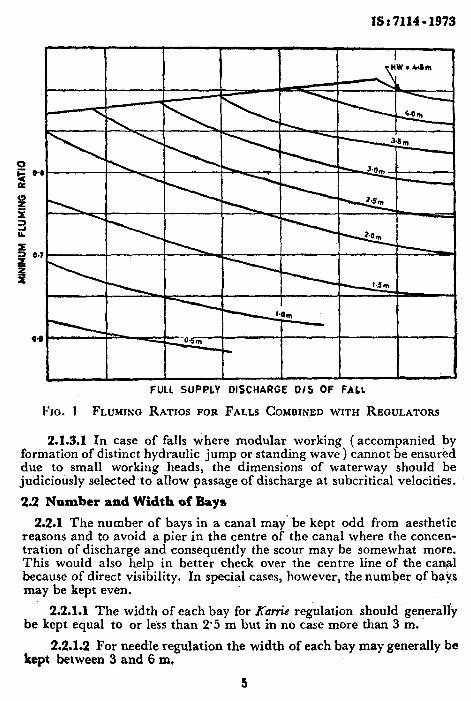
2.1.3 Where the regulator is combined wjth a fall the clear linear waterway would depend on the following two conditions:
a) For submerged falls, the drawing ratio (that is, the ratio of railwater over crest to head water over crest) should be greater than 0’8; and
b) For free falls, the discharge per unit length over the crest should be equal to or greater than that required for the available loss of head and the required value of the full supply depth downstream (generally above downstream bed level or above downstream cistern in certain cases ).
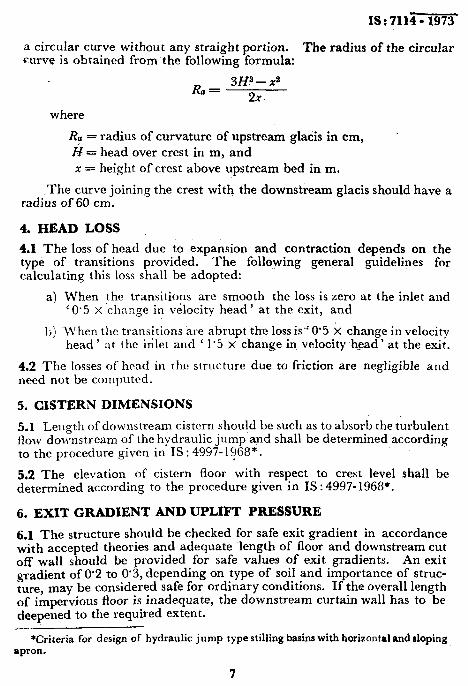
The value of fluming ratio Bt/B (that is, ratio ofclear waterway to design bed width downstream) obtained from Fig. 1 would generally be found to ensure the above two conditions and should not be kept less than 0’5 although it has to be fixed keeping in view the requirements of setting the crest in accordancewith 3.1.2.
0 5 04
a
4 E 3 IL
4
s
0.7
jE
FULL SUPPLY DISCHARGE D/S OF FALL
FIG. 1 FLUMING RATIOS FOR FALLS COMBINED WITH REGULATORS
2.1.3.1 In case of falls where modular working (accompanied by formation of distinct hydraulic jump or standing wave ) cannot be ensured due to small working heads, the dimensions of waterway should be judiciously selected to aIlow passage of discharge at subcritical velocities.
2.2 Number and Width of Bays
2.2.1 The number of bays in a canal may’ be kept odd from aesthetic reasons and to avoid a pier in the centre of the canal where the concen- tration of discharge and consequently the scour may be somewhat more. This would also help in better check over the centre line of the can@ because of direct visibility. In special cases, however, the number of bays may be kept even.
2.2.1.1 The width of each bay for K&e regulation should generally be kept equal to or less than 2.5 m but in no case more than 3 m.
kept 2.2.1.2 For needle regulation the width of each bay may generally be between 3 and 6 m,
3

IS : 7114 - 1973
2.2.1.3 For depths of flow greater than 2 m, gate regulation is adopted. The width of each bay for gate regulation should be kept in accordance with standard sizes of gates, which are readily available or can conveniently be manufactured without much loss of time and effort.
3. CREST LEVEL
3.1 In the case of unlined canals only a sill is provided. In the case of lined canals a crest is generally provided to red&e the height of regulation arrangement. The crest level shall he fixed according to 3.1.1 and 3.1.2.
3.1.1 The crest level of the cross regulator combined with fall shall be worked out using the follo\ving equation:
where
Q= full supply discharge in mg/s,
C = coefficient of discharge,
Rl = clear waterway in m, and
N= head over crest = full supply level upstream + head due ro velocity of approach ( ha ) - crest level.
Norm - In the above formula the exact value of C, th+, coefficient of discharge depends on many factors, such as the head over the sill shape and width of the crest. its height over the upstream floor and roughness. of its surface. It is, therefore, recommended that the value of C be determined by model studies where values based on prototype observations on similar structures are not available.
3.1.2 In a lined canal, setting of the crest above bed (upstream 01 downstream, whichever is higher), should not be less than 15 cm noI higher than 40 percent ~of the normal depth of the canal upstream and fluming ratio calculated according to 2.1.3 may be adjusted accordingly.
3.2 The crest profile (that is, upstream glacis, crest, downstream glacis and the radii joining the upstream and downstream glacis with the crest ) should be kept in accordance with requirements for a fall.
3.2.1 Generally for discharges higher than 10 cumecs the upstream and downstream glacis should have a ‘slope of the two horizontal to one vertical. The crest width shall be fixed from operational cosiderations subject to a minimum of 2/3 H (where H is the head over crest ). The radius joining the crest with upstream glacis should be kept equal to H and the radius joining the crest with downstream glacis should be kept eq+fai to 1.5 H.
3.2.2 For discharges lower than 10 cumecs the slope. of downstream glacis shall be kept at 2’5:l. The upstream glacis should be entireb of
6
1837114-1973
a circular~curve without any straight portion. The radius of the circular curve is obtained ~from the following formula:
R = 3H=-x= B
2x-
where
Ra = radius of curvature of upstream glacis in cm, H= head over crest in m, and x = height of crest above upstream bed in m.
The curve joining the crest with the downstream glacis should have a radius of 60 cm.
4. HEAD LOSS
4.1 The loss of head due to expansion and contraction depends on the type of transitions provided. The foilqwing general guidelines for calculating this loss shall be adopted:
a) When the transitions are smooth the loss is zero at the inlet and ( 0.5 x change in vklocity head ’ at the exit, and
Ii) When the transitions are abrupt thq loss is” 0’5 X change in velocity head’ at the &let and ‘ 1’5 x change in velocity h,cad’ at the exit.
4.2 The losses of head in the structure due EO friction are negligible and need not be computed.
5. CISTERN DIMENSIONS
5.1 Length of downstream cistern should be such as to absorb the turbulent flow downstream of the hydraulic jump and shall be determined according to the procedure given in IS : 4997- 1?68*.
5.2 The elevation of cistern floor with respect to crest level shall be determined according to the procedure given in IS : 4997-1968’.
6. EXIT GRADIENT AND UPLIFT PRESSURE
6.1 The structure should be checked for safe exit gradient in accordance with accepted theories and adequate length of floor and downstream cut off wall should be provided for safe values of exit gradients. An exit gradient of 02 to 0.3, depending on type of soil and importance of struc- ture, may be considered safe for ordinary conditions. If the overall length of impervious floor is inadequate, the downstream curtain wall has to be deepened to the required extent.
*Criteria for design of hydraulic jump type stilling basins with horizontal and sloping apron.
7
IS : 7114- 1973
6.2 The thickness of floors provided shall be sufficient to resist uplift pressures calculated in accordance with accepted theories.
6.2.1 The uplift pressures should be worked out for the following two conditions and the calculation of floor thickness shall be based on the higher value of uplift pressure:
a) When the upstream water level is headed up to full supply level and downstream cistern is pumped dry.
b) When the upstream water level is headed up to full supply level and varying discharges pass downstream.
NOTE - The maximum uplift would occur at the point where the trough of the standing wave is located.
6.2.2 In case the subsoil water level is higher than the full supply level upstream, special precautions should be taken against uplift,
6.2.3 Pressure relief arrangements should be provided in the case of important structures subjected to high uplift pressures. When these arrangements are provided suitable reduction in uplift pressures may be provided .depending upon the soil and the effectiveness and expected performance of the relief measures provided.
7. OTHER REQUIREMENTS
7.1 The upstream and downstream approaches should be smooth and should generally conform to the requirements for falls.
7.2 The upstream and downstream curtain walls, bed protection and provision of staggered blocks, if any, should conform to the requirements for falls.
7.3 The regulation arrangements may comprise of flash board (iCarrie)/ needle regulation or gate regulation or both depending on the importance of the structure. .
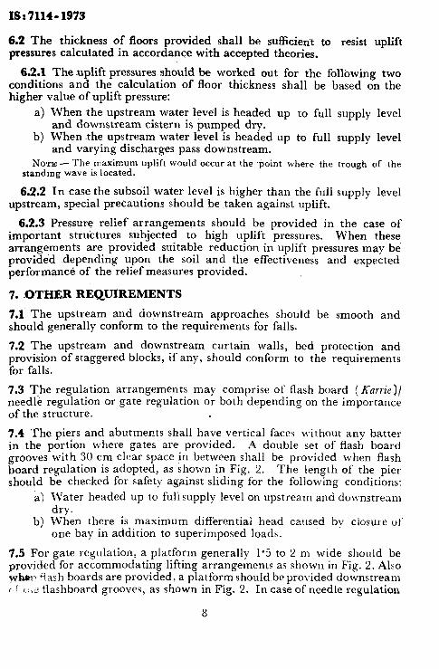
7.4 The piers and abutments shall have vertical faces without any batter in the portion where gates are provided. A double set of flash board grooves with 30 cm clear space in between shall be provided when flash board regulation is adopted, as shown in Fig. 2. The length of the piei should be checked for safety against sliding for the following conditions:
a) Water headed up to fuli supply level on upstream and do\vnstream dry.
b) When there is maximum differential head calrsed by closure 01‘ one bay in addition to superimposed loads.
7.5 For gate regulation, a platform generally 1.5 to 2 m wide should be provided for accommodating lifting arrangements as shown in Fig. 2. Also whD~> ‘iash boards are provided: a platform should be provided downstream ( : i‘ T:~Z Bashboard grooves, as shown in Fig. 2. In case of needle regulation
II
IS : 7114 - 1953
x T
--_--_ c-e -__
----_
---___
Fxo. 2 REGULATOR WITH GATE AND Karrie REGULATION
9
IS : 7114 - 1973
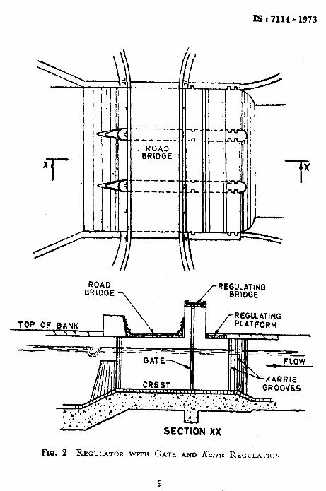
a foot rest for the needle shall be provided on the crest as shown in I&. 3.. The needles should preferably ‘have a slope of 15 and the shape of’ the abutting edge of the regulation platform should be tapered accol.dingly.
Q rNEEDLE
FIG. 3 REGULATOR WITH NEEDLE REGULATION

B”kA” OF INDIAN STANDARDS
Headquarters :
Manak Bhavan. 9 Bahadur Shah &far Marg. NEW DELHI 110002
Telephones : 331 01 31 Telegrams : Manaksanstha
331 13 75 (Common to all Offices) Regional Offices :
Central : Manak Bhavan. 9. Bahadur Shah Zafar Marg, NEW DELHI 110002
’ Eastern : l/l4 C.I.T. Scheme VII M, V.I.P. Road, Maniktola. CALCUTTA 700054
Northern : SC0 445-446, Sector 35;C. CHANDIGARH 160036 Southern
t Western : C.I.T. Campus, IV Cross Road, MADRAS 600113 : Manakalaya, E9 MIDC. Marol. Andheri (East).
BOMBAY 400093
Branch Offices : ‘Pushpak’, Nurmohamed Shaikh Marg. Khanpur, AHMADABAD 380001
t Peenya Industrial Area, 1st Stage. Bangalore-Tumkur Road, BANGALORE 660058
Gangotri Complex, 5th Floor, Bhadbhada Road. T.T. Nagar. BHOPAL 462003
Plot No. 21, Satyanagar, BHUBANESHWAR 751007 Kalai Kathir Building, 6148-A Avanasi Road, COIMBATORE 641037 Plot No 43, Sector 16A, Mathura Road, FARIDABAD 121001 Savitri Complex, 116 G. T. Road, GHAZIABAD 201001 5315 Ward No. 29, R.G. Barua Road. 5th By-lane,
GUWAHATI 781003 6-B-56C L. N. Gupta Marg. ( Nampally Station Road )
HYDERABAD 500001 R14 Yudhister Marg, C Scheme, JAIPUR 302005
1171418 B Sarvodaya Nagar, KANPUR 208005
Plot No, A-9, House No. 561/-63. Sindhu Nagar. Kanpur Road, LUCKNOW 226005
Patliputra Industrial Estate, PATNA 800013
C/o Smt. Sunita Mirakhar, 66 D/C Annexe, Gandhi Nagar, JAMMU (TAWI) 180004
T. C. No. 14/1421, University P. O., Palayam THIRUVANANTHAPURAM 695034
inspection Offices (With Sale Point) : Pushoaniali, First Floor, 205-A West Hiah Coun Road.
Shank& Nagar Square, NAGPUR 44OC?lO Institution of Engineers (India) Building. 1332 Shivaii Nagar.
PUNE 411005
‘Sales OffiCe CakUtra is at 5 Chowrlnghee Approach P. 0. Princep Street, CALCUTTA
t Sales Office is at Novelty Chambers, Grant Road, BOMBAY
$ Sales Office is at Unitv Building. Narasimharaja Square BANGALORF
Telephone
i 331 01 31
333: is3 ;25
531640 235 23 15 632 92 95
2 63 48 39 49 55
55 40 21
40 38 27 21 01 41
8-28 88 01 8-71 19 96
4-11 37
201083
521374
21 88 78
5 56 07
28 23 05
6 21 04
62 61 71
5 24 35
27 99 65
309 65 28
22 39 71
Printed at Dee Kav Printers. New Delhi. India