Embed Size (px)
Citation preview
1
Item #1001-419-054Model #7114-01
USE AND CARE GUIDE
NO CUT EASY INSTALL VENTILATION FAN
Questions, problems, missing parts? Before returning to the store, call Hampton Bay Customer Service
8 a.m. - 7 p.m., EST, Monday-Friday, 9 a.m. - 6 p.m., EST Saturday
1-855-HD-HAMPTON
HAMPTONBAY.COM
THANK YOUWe appreciate the trust and confidence you have placed in Hampton Bay through the purchase of this ventilating bath fan. We strive to
continually create quality products designed to enhance your home. Visit us online to see our full line of products available for your home improvement needs. Thank you for choosing Hampton Bay!

2
Table of Contents ........................................................... 2Safety Information .......................................................... 2Product Specifications ................................................... 3Typical Installation .......................................................... 3Wiring Diagram ............................................................... 3 Quick connect instructions ...................................................... 3Warranty .......................................................................... 4 LIMITED LIFETIME WARRANTY ................................................ 4 What is Covered...................................................................... 4
Pre-installation................................................................ 4 Planning Installation ................................................................ 4 Tools Required ........................................................................ 4 Hardware Included .................................................................. 5 Package Contents ................................................................... 5Installation - New Construction .................................... 6Installation - Existing Construction .............................. 8Care and Maintenance ................................................. 11Troubleshooting ............................................................ 11
Table of Contents
Safety InformationPlease read and understand this entire manual before attempting to assemble, operate or install the product.
1. Always disconnect the power supply prior to servicing the fan, motor or junction box.
2. Installation work must be carried out by a qualified person(s) in accordance to all local and safety codes including the rules for fire-rated construction.
3. Follow all local building, safety and electrical codes as well as NEC (National Electrical Code) and OSHA (Occupational Safety and Health Act).
4. Electric Service supply must be 120 volts, 60 hertz.
5. This unit must be properly grounded.
6. Do not bend or kink the power wires.
7. Exercise care to not damage existing wiring when cutting or drilling into walls or ceilings.
8. Sufficient air supply is required for proper combustion and the exhaustion of gases through the chimney (flue) of fuel burning equipment to prevent back-drafting. See the standards of NFPA (National Fire Protection Association) and ASHRAE (American Society for Heating Refrigeration and Air Conditioning Engineers) and the local building code authorities.
9. Do not use this fan with any solid state control device, such as a remote control, dimmer switch, or certain timers. Mechanical timers are not solid state devices.
10. This ventilation fan is approved for use over a bathtub or shower when installed in a GFCI protected circuit. Do not use fans over a bathtub or shower that are not approved for that application and marked accordingly.
11. Do not install in a cooking area.
12. Do not use to exhaust hazardous or explosive vapors.
13. Fans should always be vented to the exterior and in compliance with local codes.
14. Do not install in a ceiling with insulation greater than R40.
15. Duct work should be installed in a straight line with minimal bends.
16. Duct work size must be the same size as the discharge and should not be reduced. Reducing the duct size may increase fan noise.
17. Prior to service or cleaning this unit, shut off power supply at the panel and lock to prevent the power from being turned on. If the panel cannot be locked, clearly mark the panel with a warning tag to prevent the power from being turned on.
18. Use this unit in the manner intended by the manufacturer. If you have any questions. Please call customer service.
19. To reduce the risk of injury to persons, install the fan at least 8.2 feet (2.5m) above the floor.

3 HAMPTONBAY.COMPlease contact 1-855-HD-HAMPTON for further assistance.
Product Specification
Typical Installation
Wiring Diagram
SPECIFICATIONS SPECIFICATIONSAirflow: 50 CFM Power consumption: 8.0 W
120 V, 60 Hz Weight: 3.65 lbs.
Duct diameter: 3 in. Ceiling Opening Dimension Requirements: 7-1/2 in. (L) x 7-1/4 in. (W) x 4 in. (H)Sound output: 1.0 Sone
QUICK CONNECTOR INSTRUCTIONSTo be sold only with installation instructions.WARNING: Wiring must comply with all applicable electricalcodes. Turn OFF power before removing or installing connectors.WARNING: COPPER TO COPPER ONLY. Do not use Aluminum wire.CAUTION: Accessory part (quick connector) should meetinstallation instructions below.NOTE: The connector is reusable on solid wires of the same wire gage or smaller. Do not reuse the connector on stranded wires.
• Strip wires 3/8"-1/2"• Grip the wire firmly and push the stripped end of the wire into the open port of the connector. Use only one conductor per port.• Verify the stripped end of the wires is fully inserted to the back of the connector.
Quickconnect
Housewires Product
wires
NOTE: Important wire information. Maximum temperature rating 105˚C (221˚F). 600 volts maximum for building wire and 1000 volts maximum for building wire and 1000 volts maximum in signs and lighting fixtures.The acceptable wire range includes: Solid: 12-18 AWG.
The ducting from this fan to the outside of the building has a strong effect on the air flow, noise and energy use of the fan. Use the shortest, straightest duct routing possible for best performance, and avoid installing the fan with smaller ducts than recommended. Insulation around the ducts can reduce energy loss and inhibit mold growth. Fans installed with existing ducts may not achieve their rated air flow.

4
LIMITED LIFETIME WARRANTY
WHAT IS COVEREDIf this product fails due to a defect in materials or workmanship at any time during the first FIVE years of ownership, the manufacturer will replace it free of charge, postage-paid at their option. This warranty does not cover products that have been abused, altered, damaged, misused, cut or worn. This warranty does not cover use in commercial applications. Use only manufacturer-supplied genuine warranty repair replacement parts to repair this fan. Use of non-genuine repair parts will void your warranty. The manufacturer DISCLAIMS all other implied or express warranties including all warranties of merchant-ability and/or fitness for a particular purpose. As some states do not allow exclusions or limitations on an implied warranty, the above exclusions and limitations may not apply. This warranty gives you specific legal rights, and you may have other rights that vary from state to state.
This warranty is limited to the replacement of defective parts only. Labor charges and/or damage incurred during installation, repair, replacement as well as incidental and consequential damages connected with the above are excluded. Any damage to this product as a result of neglect, misuse, accident, improper installation or use other than the purpose SHALL VOID THIS WARRANTY. Shipping costs for return product as part of a claim on the warranty must be paid for by the customer.
Contact the Customer Service Team at 1-855-HD-HAMPTON or visit www.HAMPTONBAY.com.
Warranty
Pre-installation
PLANNING INSTALLATIONBefore beginning assembly of the product, make sure all parts are present. Compare parts with the package contents list and hardware contents. If any part is missing or damaged, do not attempt to assemble the product.
WARNING: Turn off electricity at breaker box before beginning installation.
Carefully remove the unit from the carton.
Check area above installation location to be sure that wiring can run to the planned location and that duct work can be run and the area is sufficient for proper ventilation.
Inspect duct work and wiring before proceeding with installation.
Before installation, provide inspection and future maintenance access at a location that will not interfere with installation work.
You may need the help of a second person to install this fan; one person on the attic side and one on the room side.
NOTE: Installation may vary depending on how the previous bath fan was installed. Supplies necessary for the installation of your bath fan are not all included. However, most are available at your local home improvement or hardware store.
TOOLS REQUIRED (not included)
Claw hammer
Drill bits
Flathead screwdriver Nails Duct
tape
Phillips head screwdriver
Utility knife
Electric drill

5 HAMPTONBAY.COMPlease contact 1-855-HD-HAMPTON for further assistance.
Pre-installation (continued)
PACKAGE CONTENTS
Part Description Quantity
A Fan body 1
B Grille 1
C Duct connector 1
A
B
C
6
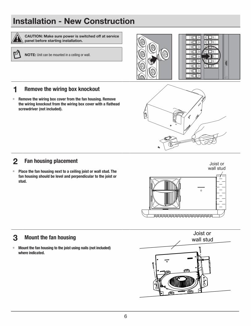
Installation - New Construction
CAUTION: Make sure power is switched off at service panel before starting installation.
NOTE: Unit can be mounted in a ceiling or wall.
1 Remove the wiring box knockout
Remove the wiring box cover from the fan housing. Remove the wiring knockout from the wiring box cover with a flathead screwdriver (not included).
2 Fan housing placement Joist or wall stud
Place the fan housing next to a ceiling joist or wall stud. The fan housing should be level and perpendicular to the joist or stud.
3 Mount the fan housingJoist or wall stud
Mount the fan housing to the joist using nails (not included) where indicated.

7 HAMPTONBAY.COMPlease contact 1-855-HD-HAMPTON for further assistance.
Installation - New Construction (continued)
4 Connect house and fan wires
Housewires Product
wires
Quickconnector
Pull the wire through the hole and into the junction box (not included). Using a quick connector, secure 120 VAC house wiring from the wall switch to the fan as shown in the wiring diagram on page 3.
NOTE: Unit can be mounted in a ceiling or wall.
CAUTION: If the electrical wires do not match the colors listed, you must determine what each house wire represents before connecting. You may need to consult an electrical contractor to determine safely.
Push the wires back through the hole. Reattach the wiring box cover.
5 Install the duct
Ceiling
3 in. duct
Duct tape or clamp
Install a circular 3 in. duct (not included) and secure it with duct tape or clamps (neither included).
Finish ceiling work. The ceiling hole should be aligned with the edge of the fan housing.
6 Install the grille
Pinch the mounting springs on the grille (B) and insert them into the narrow rectangular slots inside the fan. Push the grille (B) up toward ceiling.
Turn on electricity at the breaker box after finishing installation.
B

8
Installation - Existing Construction
CAUTION: Turn off electricity at breaker box before beginning installation. Review all safety precautions.
1 Remove the existing fan Remove the old fan from the ceiling.
2 Measure the ceiling opening
Measure the opening to assure it is large enough to accom-modate the new fan body (A) (7.50 in. x 7.25 in.).
NOTE: 7.25 inch side of the opening should be flush with the joist.
3 Enlarge the opening (optional)
7.50"
7.25"
If this fan is not replacing an old fan, be sure to cut a 7.50 in. x 7.25 in. opening for the fan body (A). MAKE SURE THE 7.25 IN. SIDE OF THE OPENING IS FLUSH WITH THE JOIST FOR INSTALLATION FROM BELOW.
9 HAMPTONBAY.COMPlease contact 1-855-HD-HAMPTON for further assistance.
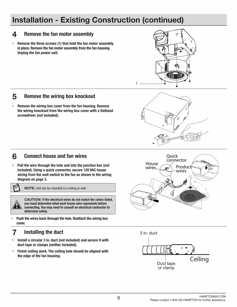
Installation - Existing Construction (continued)
4 Remove the fan motor assembly
Remove the three screws (1) that hold the fan motor assembly in place. Remove the fan motor assembly from the fan housing. Unplug the fan power unit.
5 Remove the wiring box knockout
Remove the wiring box cover from the fan housing. Remove the wiring knockout from the wiring box cover with a flathead screwdriver (not included).
6 Connect house and fan wiresHousewires Product
wires
Quickconnector
Pull the wire through the hole and into the junction box (not included). Using a quick connector, secure 120 VAC house wiring from the wall switch to the fan as shown in the wiring diagram on page 3.
NOTE: Unit can be mounted in a ceiling or wall.
CAUTION: If the electrical wires do not match the colors listed, you must determine what each house wire represents before connecting. You may need to consult an electrical contractor to determine safely.
Push the wires back through the hole. Reattach the wiring box cover.
7 Installing the duct
Ceiling
3 in. duct
Duct tape or clamp
Install a circular 3 in. duct (not included) and secure it with duct tape or clamps (neither included).
Finish ceiling work. The ceiling hole should be aligned with the edge of the fan housing.
1

10
Installation - Existing Construction (continued)
8 Insert the fan housing Insert the fan housing through the existing hole in the ceiling.
The fan housing should be level and perpendicular to the joist or stud.
9 Mount the fan housing to the joist Joist or wall stud Mount the fan housing to the joist or stud using nails (not
included) where indicated by arrows inside the fan housing.
10 Reattach the motor assembly
Plug the motor assembly back into the power unit. Reattach the motor assembly using the three screws (1) removed in step 4.
11 Install the grille
Pinch the mounting springs on the grille (B) and insert them into the narrow rectangular slots inside the fan. Push the grille (B) up toward the ceiling.
Turn on electricity at the breaker box after finishing installation.
B
1

11 HAMPTONBAY.COMPlease contact 1-855-HD-HAMPTON for further assistance.
Troubleshooting
WARNING: Disconnect power supply before servicing.
See SAFETY INFORMATION before proceeding. Routine maintenance should be done at least once a year.
Never use solvents, thinner or harsh chemicals for cleaning the fan.
Do not allow water to enter the motor.
Do not immerse metal parts in water.
Care and Maintenance
Problem Possible Cause Solution
The fan seems louder than it should.
The CFM is too great.Be sure the CFM rating on the fan matches the square footage of your room.
The damper is damaged or not working properly.Check the damper to ensure it is opening and closing properly. If the damper has become damaged, please call Customer Service.
The bend in the duct is too close to the fan discharge.Be sure you do not have any sharp bends in the duct closer than 18 in. to the fan discharge.
The fan discharge is reduced to fit a smaller duct. Use the recommended size ducting to reduce fan noise.
The fan body is not attached securely. Be sure the fan is securely attached to the ceiling joists.
The fan is not clearing the room.
There is insufficient airflow intake in the room.Be sure a door or window is slightly ajar or opened to allow airflow. The fan is not able to draw air out of the room without enough airflow to draw from.
There is insufficient CFM. Be sure the CFM rating on the fan matches the requirements for your room size.
NOTE: Using a tissue is not the correct method for determining if the fan is operating properly. If the fan clears steam from the room within approximately 15 minutes of completeing your shower, then the fan is operating properly.

12
Questions, problems, missing parts? Before returning to the store, call Hampton Bay Customer Service8 a.m. - 7 p.m., EST, Monday-Friday,
9 a.m. - 6 p.m., EST, Saturday
1-855-HD-HAMPTON
HAMPTONBAY.COM
Retain this manual for future use.