Embed Size (px)
Citation preview

Disclosure to Promote the Right To Information
Whereas the Parliament of India has set out to provide a practical regime of right to information for citizens to secure access to information under the control of public authorities, in order to promote transparency and accountability in the working of every public authority, and whereas the attached publication of the Bureau of Indian Standards is of particular interest to the public, particularly disadvantaged communities and those engaged in the pursuit of education and knowledge, the attached public safety standard is made available to promote the timely dissemination of this information in an accurate manner to the public.
इंटरनेट मानक
“!ान $ एक न' भारत का +नम-ण”Satyanarayan Gangaram Pitroda
“Invent a New India Using Knowledge”
“प0रा1 को छोड न' 5 तरफ”Jawaharlal Nehru
“Step Out From the Old to the New”
“जान1 का अ+धकार, जी1 का अ+धकार”Mazdoor Kisan Shakti Sangathan
“The Right to Information, The Right to Live”
“!ान एक ऐसा खजाना > जो कभी च0राया नहB जा सकता है”Bhartṛhari—Nītiśatakam
“Knowledge is such a treasure which cannot be stolen”
“Invent a New India Using Knowledge”
है”ह”ह
IS 4377 (1981): General requirements for magnetic soundtape recording and reproducing systems [LITD 7: Audio,Video and Multimedia Systems and Equipment]

IS : 4377 - 1981
Indian Standard GENERAL REQUIREMENTS FOR
MAGNETIC SOUND TAPE RECORDING AND REPRODUCING SYSTEMS
( First Revision ) Recording Sectional Committee, LTDC 23
Chairman
SHRI P. R. NARASIMHAN
Members
SHRI J. N. BISARIA ( Alternate to Shri P. R. Narasimhan )
SHRI L. H. BHATIA SHRI N. P. BITATTACRARYA DR A. F. CHHAPCAR SHRI P. H. GANATRA
SHRI M. SAJJAD ( Alternate) SHRI D. K. GHOSH
SHR~ ARUN BAGRI ( Alternate ) DR R. G. GUPTA
Representing
Directorate General of All India Radio, New Delhi
Polydor of India Ltd, Bombay Department of Teaching Aids, New Delhi National Physical Laboratory ( CSIR ), New Delhi Vimal Enterprises Ltd, Umbergam
The Gramophone Co of India Ltd, Calcutta
Department of Electronics, New Delhi
Ministry of Defence ( DGI ) DR P. N. GUPTA ( Alternote )
COL L. G. KETKAR LT COL G. R. MAHADEVAN ( Altarnate )
DR C G. KHOT Railway Board, New Delhi SHRI S. JAIN (.Alternate)
SHRI S. C. MAZUMDAR Central Electronics of Haryana Pvt Ltd, Faridabad SHRI M. N. MEHTANI Directorate General Doordarshan, New Delhi
SHRI S. S. SWANI (Alternate ) SHRI A. G. NAKASIMHA Directorate General of Civil Aviation, New Delhi
SMT V. RATNAVATI (Alternate) SHRI S. C. PATEL Bharat Electronics Ltd, Bangalore SHRI K. D. PAVATE Central Electronics Engineering Research Institute
( CSIR ), Pilani SHRI M. R. KAPOOR ( AIternate)
SHRI A. V. RAMANAN Films Division, Bombay SHRI P. D. RAO Electronic Component Industries Association
( ELCINA ), New Delhi SHRI P. V. KRISHNA REDDI Film and Television Institute of India, Pune RESEARCH ENGINEER Research Department, All India Radio, New Delhi
( Continued on page 2 )
@ Copyright 1981
INDIAN STANDARDS INSTITUTION
This publication is protected under the Indian Copyrighr Act (XIV of 1957 ) and reproduction in whole or in part by any means except with written permission of the publisher shall be deemed to be an infringement of copyright under the said Act.
IS : 4377 - 1981
( Continued from page 1 )
Members
SHRI M. SANKARALINGAM
SHRIJ. S. PASSI ( ALternate) SHRI S. K. SARAP
Representing
Directorate General of Supplies & Disposals ( Inspection Wing), New Delhi
Peico Electronics and Electricals Ltd, Bombay; and the Radio Eiectronic & Television Manufac- turers’ Association, Bombay
SHRI A. DAS GUPTA (Alternate) SHRI R. C. JAIN, Director General, IS1 ( Ex-o&&o Member )
Head (Electronics )
Secretary
SHRI PAVAN KUMAR
Assistant Director ( Electronics ), IS1
Panel for Magnetic Tapes for Sound Recording and Reproduction, LTDC 23 : PI
Convener
DR A. P. CHHAPGAR National Physical Laboratory ( CSIR), New Delhi
Members
SHRI J. N. BISARIA Directorate General of All India Radio, New Delhi SHRI P. H. GANATRA Vimal Enterprises Ltd, Umbergam
SHRI M. SAJJAD (Alternate) SHRI D. K. GHOSH The Gramophone Co of India Ltd, Calcutta
SHRI ARUN BAGRI ( Alternate ) RESEARCH ENGINEER Research Department, All India Radio, New Delhi SHRI M. SANKARALINGAM Directorate General of Supplies & Disposals
( Inspection Wing ), New Delhi SHRI J. S. PASSI (Alternate )
Is :4377-1981
Indian Standard GENERAL REQUIREMENTS FOR
MAGNETIC SOUND TAPE RECORDING AND REPRODUCING SYSTElMS
( First Revision )
0. FOREWORD
0.1 This Indian Standard was adopted by the Indian Standards Institution on 22 April 1981, after the draft finalized by the Recording Sectional Committee had been approved by the Electronics and Telecommunication Division Council.
0.2 This Indian Standard covers the general requirements for magnetic sound tape recording and reproducing systems.
0.3 This Indian Standard was originally published in 1967. The revision has been undertaken to include the latest requirements of magnetic tapes including cassettes and tape recording equipment. Other Indian Standards so far published in this series are:
IS : 4479-1981 Methods of measurements on magnetic tapes for sound recording and reproduction (first revision )
IS : 4480 (.Part I )-1967 Magnetic tapes for sound recording and re- production : Part I Domestic grade
IS : 4480 ( Part II )-1974 Magnetic tapes for sound recording reproduc- tion : Part II Professional grade
IS : 6370-1981 Tape cassettes for domestic use (Jirst revision )
IS : 7068-1973 Specification for 6.25 mm calibration tape
IS : 7594 ( Part I )-1978 Magnetic sound tape recording and repro- ducing equipment ( cassette) : Part I Methods of measurement
IS : 7594 ( Part II )-1979 Magnetic sound tape recording and reproduc- ing equipment ( cassette ) : Part II Domestic type
IS : 8 152-1976 Method of measurement of speed fluctuations in sound recording and reproducing equipment
IS : 8234-1976 Spools for magnetic tapes for sound recording and reproduction
3
IS : 4377 - 1981
IS : 8655 ( Part I )-1977 Magnetic sound tape recording and reproduc ing equipment ( reel-to-reel ) : Part I Methods of measurement
IS : 8655 ( Part III )-1978 Magnetic sound tape recording and repro- ducing equipment ( reel-to-reel ) : Part III Professional type
0.4 While preparing this standard assistance has been derived from the following documents issued by the International Electrotechnical Com- mission :
IEC Dot : 60A ( CO. ) 54 Draft-Revision of IEC Publication 94 : Magnetic tape recording and reproducing systems Part 1 : General conditions and requirements.
IEC Dot : 60 A ( Sectt ) 77 Revision of IEC Publication 94 Draft- Proposal for IEC Publication 94 Part 6 : Reel-to-reel systems. Mechanical requirements and dimensions, including reels, hubs and relevant track allocations.
0.5 For the purpose of deciding whether a particular requirement of this standard is complied with, the final value, observed or calculated, express- ing the result of a test, shall be rounded off in accordance with IS : 2-1960*. The number of significant places retained in the rounded off value should be the same as that of the specified value in this standard.
1. SCOPE
1.1 This standard specifies the mechanical requirements for the magnetic tape; electrical requirements for the magnetic recording and reproducing system; and tape programme identification. It includes requirements for reel-to-reel and cassette recording/reproducing systems including non- perforated magnetic tapes and magnetic tape records. This standard excludes high-speed duplicating equipment.
2. TERMINOLOGY
2.1 For the purpose of this standard, the terms and definitions given in IS : 1885 ( Part XLVIII/Sec l)-19787 shall apply.
3. DESIGN
3.1 The magnetic sound tape recording and reproducing system shall be so designed as to be capable of operation and storage at ambient temperature ranging from - 10” to +55”C and relative humidity not exceeding 95 percent. -
*Rules for rounding off numerical values ( seuised).
tElectrotechnica1 vocabulary: Part XLVIII Recording, Section 1 Tape recording.
4
IS : 4377 - 1981
4. RADIO INTERFERENCE
4.1 The limits of the radio interference from tape recorder shall not exceed those specified in 7 of IS : 6842-1972”.
5. SAFETY
5.1 In so far as mains operation of the equipment is concerned, it shall conform to the requirements specified in IS : 616-19577.
6. UNITS AND SYMBOLS
6.1 The letter symbols for quantities and units shall be in accordance with relevant Indian Standards or as specified.
7. MECHANICAL AND ELECTRICAL MATCHING REQUIREMENTS
7.1 The mechanical design features for the connectors used shall be in accordance with relevant Indian Standards or as specified.
7.2 The preferred matching values shall be in accordance with relevant Indian Standards or as specified.
8. MECHANICAL SPECIFICATION
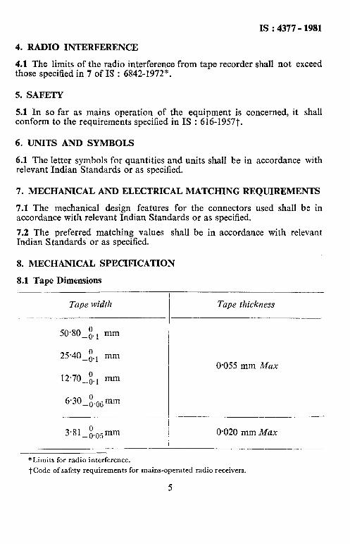
8.1 Tape Dimensions
Tape width
5030_~. 1 mm
25*40-i., mm
12.70-z. 1 mm
6*30_~.u6:mm
Tape thickness
0.055 mm Max
3.81 _&),mm O-020 mm Max
*Limits for radio interference.
t Code of safety requirements for mains-operated radio receivers.
5
IS : 4377 - 1981
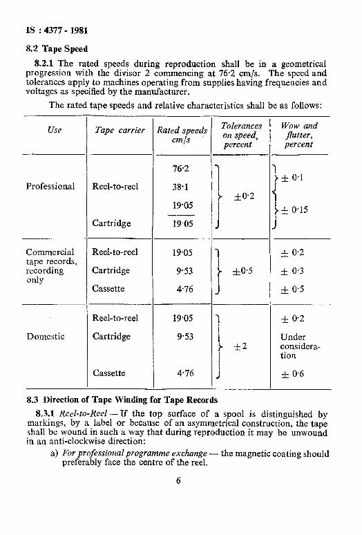
8.2 Tape Speed
8.2.1 The rated speeds during reproduction shall be in a geometrical progression with the divisor 2 commencing at 76.2 cm/s. The speed and tolerances apply to machines operating from supplies having frequencies and voltages as specified by the manufacturer.
The rated tape speeds and relative characteristics shall be as follows:
Use
Professional
Commercial tape records, recording only
Domestic
Tape carrier
Reel-to-reel
Cartridge
Reel-to-reel 19.05
Cartridge 9.53
Cassette 4.76
Reel-to-reel
Cartridge
19.05
9.53
Cassette 4.76
Rated speeds cmfs
76.2
38.1
19.05
19m
Tolerances on speed, percent
7
+ Ito-
J
I
’ f0.5
1 7 i rt2
I J
Wow and flutter, percent
f 0.2
Under considera- tion
f 0.6
8.3 Direction of Tape Winding for Tape Records
8.3.1 Reel-to-Reel- If the top surface of a spool is distinguished by markings, by a label or because of an asymmetrical construction, the tape shall be wound in such a way that during reproduction it may be unwound in an anti-clockwise direction:
a) For professional programme exchange - the magnetic coating should preferably face the centre of the reel.
6
IS : 4377 - 1981
b) For domestic use - the magnetic coating shall face the centre of the reel.
8.3.2 Cassette for Professional Programme Exchange, and Domestic Use - The magnetic coating shall face the openings at the front of the cassette.
8.4 Designation, Allocation and Dimensions of Magnetic Tracks
8.4.1 Designation of Magnetic Tracks - Under normal operation, the designation of magnetic tracks shall be as follows:
a) Reel-to-Reel - If the tape moves from left to right with the mag- netic coating facing away from the observer and with the leader to the right, the top track is designated No. 1 track, the next lower track is designated No. 2 track, and so on.
b) Cassette - If the tape moves from left to right with the magnetic coating side facing towards the observer, with the leader to the right and side 1 ( A ) uppermost, the bottom track is designated No. 1 track, the next upper track is designated No. 2 track, and so on.
8.4.2 Allocation and Dimensions of Magnetic Tracks for Reel-to-Reel Tape - (See Fig. 1).
8.4.2.1 Tapes for professional programme exchange
a) Monophonic - A single track shall extend over the whole width of the tape.
b) Stereophonic
i) Two tracks shall be recorded in the same direction, No. 1 track shall carry the recording for the left-hand channel, as viewed from the listening position; No. 2 track shall carry the recording for the right-hand channel.
ii) The track shall be recorded with the hand-gaps in line and phased for reproduction on equipment so connected that when a full track tape is reproduced it produces in-phase sound pressures at the right- and left-hand loudspeakers.
iii) Both tracks shall be recorded to the respective outer edges but a guard track at least 0.75 mm wide in the centre of the tape shall be left free from intentional recording. NOTE - A guard track width of 2 mm is sometimes used.
8.4.2.2 Domestic tape records
a) Monophonic two-track tape records
i) Two tracks shall be recorded in sequence in alternate directions, No. 1 track first, No. 2 track second.
7
IS : 4377 - 1981
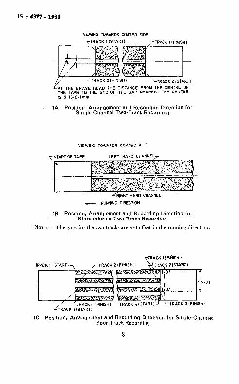
VlEWlNG TOWARDS COATED SIDE
TTRACK 1 (STARTI /-TRACK 1 I FlNlSH I
Y /TRACK 2 IFINISHI \TRACK 2 (START 1
AT THE ERASE HEAD THE DISTANCE FROM THE CENTRE OF THE TAPE TO THE END OF THE GAP NEAREST THE CENTRE IS 0.15*0.1 mm
IA Position, Arrangement and Recording Direction for Single Channel Two-Track Recording
VIEWING TOWARDS COATED SIDE
- RUNNING DIRECTION
If3 Position, Arrangement and Recording Direction for Stereophonic Two-Track Recording
NOTE - The gaps for the two tracks are not offset in the running direction.
IC Position, Arrangement and Recording Direciion for Single-Channel Four-Track Recording
8
IS : 4377 - 1981
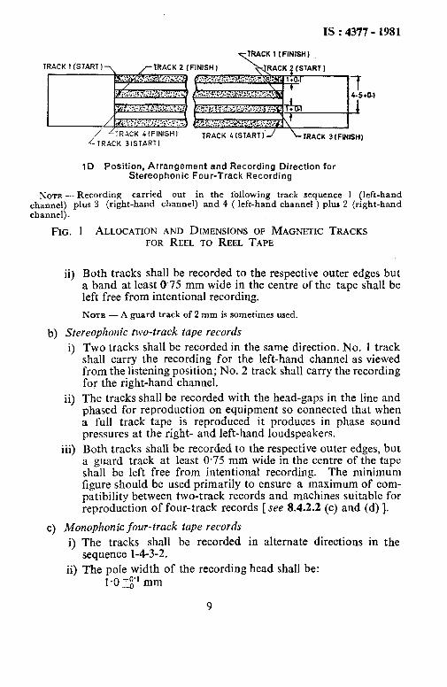
ACK I I FINISH )
1
1D Position, Arrangement and Recording Direction for Stereophonic Four-Track Recording
NOTE - Recording carried out in the following track sequence 1 (left-hand channel) plus 3 (right-hand channel) and 4 ( left-hand channel ) plus 2 (right-hand channel).
FIG.
ii)
1 ALLOCATION AND DIMENSIONS OF MAGNETIC TRACKS FOR REEL TO REEL TAPE
Both tracks shall be recorded to the respective outer edges but a band at least 0.75 mm wide in the centre of the tape shall be left free from intentional recording.
NOTE - A guard track of 2 mm is sometimes used.
b) Stereophonic two-track tape records
0
ii)
iii)
Two tracks shall be recorded in the same direction. No. 1 track shall carry the recording for the left-hand channel as viewed from the listening position; No. 2 track shall carry the recording for the right-hand channel.
The tracks shall be recorded with the head-gaps in the line and phased for reproduction on equipment so connected that when a full track tape is reproduced it produces in phase sound pressures at the right- and left-hand loudspeakers.
Both tracks shall be recorded to the respective outer edges, but a guard track at least 0.75 mm wide in the centre of the tape shall be left free from intentional recording. The minimum figure should be used primarily to ensure a maximum of com- patibility between two-track records and machines suitable for reproduction of four-track records [see 8.4.2.2 (c) and (d) 1.
C) Monophonic four-track tape records
i) The tracks shall be recorded in alternate directions in the sequence l-4-3-2.
ii) The pole width of the recording head shall be: 1.3 +J mm
9
Is : 4371- 1981
iii) The distance between the outer edges of tracks 1 and 3 or of tracks 2 and 4 shall be:
4.5 tr’ mm
iv) Tracks 1 and 4 shall be so positioned that their outer edges coincide with the edges of the tape when the tape width is at minimum.
d) Stereophonic four-track tape records
i) Tracks 1 and 3 shall be used simultaneously for one direction of tape travel, tracks 2 and 4 for the other direction.
ii) Tracks 1 and 4 shall carry the recording for the left-hand channel as viewed from the listening position, tracks 3 and 2 shall carry the recording for the right-hand channel.
iii) The tracks shall be recorded with the head-gaps in line and shall be phased for reproduction on equipment so connected that when a full track tape is reproduced it produces in-phase sound pressure at the right- and left-hand loudspeakers.
iv) The pole width of the recording head shall be:
l*O+,O” mm
v) The distance between the outer edges of tracks 1 and 3 or of tracks 2 and 4 shall be:
4.5 f_ t1 mm
vi) Tracks 1 and 4 shall be so positioned that their outer edges coincide with the edges of the tape when the tape width is at minimum.
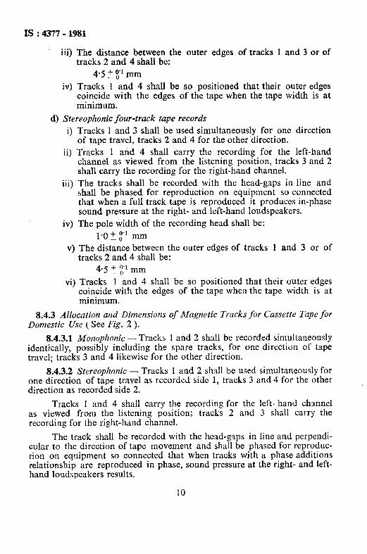
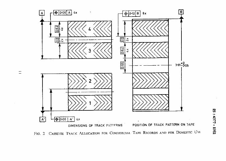
8.4.3 Allocation and Dimensiorls of Magnetic Tracks for Cassette Tape for Domestic rise ( See Fig. 2 ).
8.4.3.1 Monophonic - Tracks 1 and 2 shall be recorded simultaneously identically, possibly including the spare tracks, for one direction of tape travel; tracks 3 and 4 likewise for the other direction.
8.4.3.2 Stereophonic - Tracks 1 and 2 shall be used simultaneously for one direction of tape travel as recorded side 1, tracks 3 and 4 for the other direction as recorded side 2.
Tracks 1 and 4 shall carry the recording for the left- hand channel as viewed from the listening position; tracks 2 and 3 shall carry the recording for the right-hand channel.
The track shall be recorded with the head-gaps in line and perpendi- cular to the direction of tape movement and shall be phased for reproduc- tion on equipment so connected that when tracks with a phase additions relationship are reproduced in phase, sound pressure at the right- and left- hand loudspeakers results.
IS : 4377 - 1981
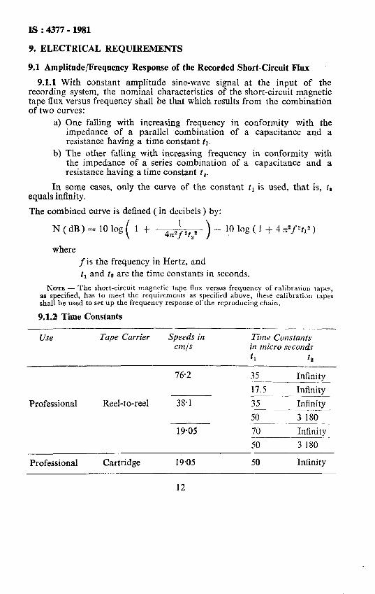
9. ELECTRICAL REQUIREMENTS
9.1 Amplitude/Frequency Response of the Recorded Short-Circuit Flux
9.1.1 With constant amplitude sine-wave signal at the input of the recording system, the nominal characteristics of the short-circuit magnetic tape flux versus frequency shall be that which results from the combination of two curves:
a) One falling with increasing frequency in conformity with the impedance of a parallel combination of a capacitance and a resistance having a time constant tl.
b) The other falling with increasing frequency in conformity with the impedance of a series combination of a capacitance and a resistance having a time constant t,.
In some cases, only the curve of the constant t, is used, that is, t, equals infinity.
The combined curve is defined ( in decibels ) by:
N(dB)=lOlog 1 + log ( 1 + 4 x”f 2t12 )
where f is the frequency in Hertz, and tl and t2 are the time constants in seconds.
NOTE - The short-circuit magnetic tape flux versus frequency of calibration tapes, as specified, has to meet the requirements as specified above, these calibration tapes shall be used to set up the frequency response of the reproducing chain.
9.1.2 Time Constants
Use Tupe Carrier
Professional Reel-to-reel
Professional Cartridge
Speeds in cm/s
76.2
38.1
19.05
19.05
Time Constants in micro seconds
t1 12
35 Infinity -~ 17.5 Infinity
35 Infinity
50 3 180 .______~~._ 70 Infinity
50 3 180
50 Infinity
12
IS : 4317 - 1981
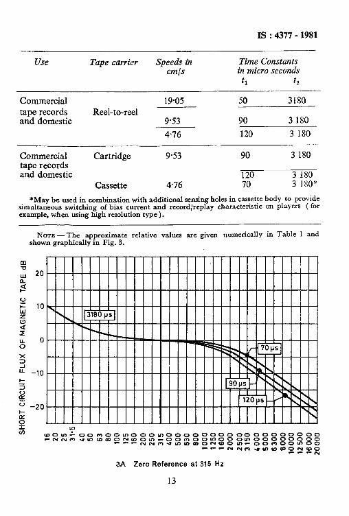
Use Tape carrier Speeds in Time Constants cm/s in micro seconds
t1 ta
Commercial 19.05 50 3180 tape records Reel-to-reel and domestic 9.53 90 3 180
4.76 120 3 180
Commercial Cartridge 9.53 90 3 180 tape records and domestic 120 3 180
Cassette 4.76 70 3 180*
*May be used in combination with additional sensing holes in cassette body to provide simultaneous switching of bias current and record/replay characteristic on players ( for example, when using high resolution type ).
NOTE -The approximate relative values are given numerically in Table 1 and shown graphically in Fig. 3.
3A Zero Reference at 315 Hz
13
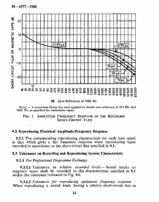
IS : 4377 - 1981
specified in 9.1 the output of the reproducing equipment shall be indepen- dent of Frequency within the tolerances indicated in Fig. 4A.
NOTE- The effect of fringing must be taken into account when making this measurement.
9.3.1.3 Channel unbalance for multichannel recordings - For multi- channel recording, the level difference between any two channels at every frequency between 80 Hz and 8 000 Hz shall not exceed 2 dB. For a stereophonic pair, the level difference shall not exceed 1.5 dB.
9.3.2 Commercial Tape Records and Domestic Use
9.3.2.1 Tolerances for reproducing equipment frequency response - When reproducing a sound track having a relative short-circuit flux as specified in 9.1 the output of the reproducing equipment shall be indepen- dent of frequency within the tolerances indicated in Fig. 4B.
9.3.2.2 Tolerances for recording/reproducing equipment frequency res- ponse - The overall frequency response of recording/reproducing equipment shall be within the tolerances indicated in Fig. 4B.
The reference and calibration tapes used for the measurement shall be specified.
10. TAPE AND PROGRAMME IDENTIFICATION
10.1 Identification of Tape Sides
10.1.1 It is recommended that, whenever possible, the non-sensitive side of the tape be indentified.
10.2 Programme Identification
10.2.1 For Professional Programme Exchange, Reel-to-Reel
10.2.1.1 The beginning of a recorded programme shall be identified by one of the following methods:
a) If there is a non-magnetic identification strip, the trailing edge of the strip should precede the beginning of the programme by one second.
b) If there is no identification strip, a visual marker (preferably metal-coated ) should be struck to the non-sensitive side of the tape one second before the beginning of the programme.
10.2.1.2 The length of tape corresponding to one second is calculated for the rated tape speed.
15
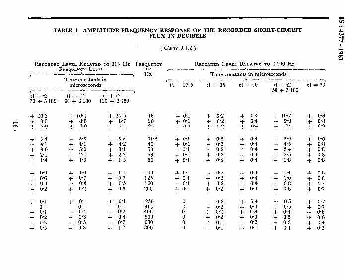
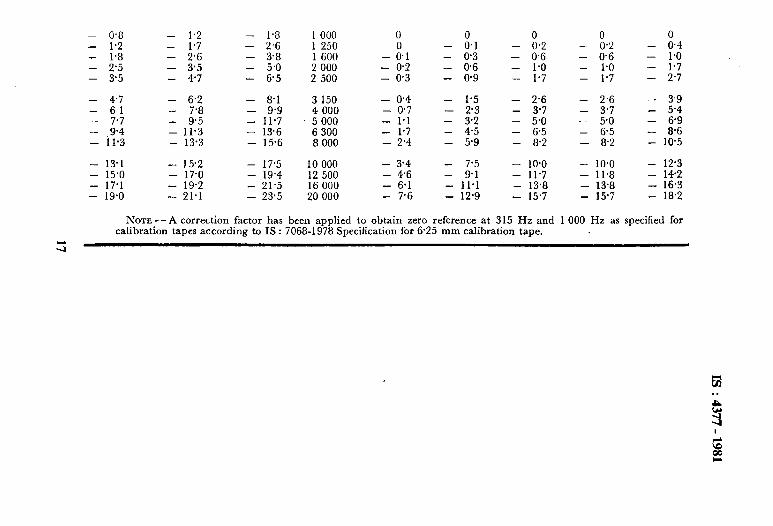
TABLE 1 AMPLITUDE FREQUENCY RESPONSE OF THE RECORDED SHORT-CIRCUIT FLUX IN DECIBELS
( muse 9.1.2 )
RECORDED LEVEL RELATED TO 315 Hz FREQUENCY RECORDED LEVEL RELATED TO 1 000 Hz FREQUENCY LEVEL r------ _--__---h~~-___~--~__-~
r-------- h------~ l% Time constants in microseconds Time constants in r----------- h----- P------
microseconds F--------
h____--_-~
t1 +t2 tl + t2 tl + t2 70 + 3 180 90 + 3 180 120 + 3 180
t1 = 17.5 t1 -I- t2 tl = 76 50 + 3 180
+ IO.3 + 1@4 + IO.5
s + 8.6 + 8.6 7.0 + + 7.0 + + 8.7 7.1 .
2 25
+ IO.7 + 9.0 + 7.4 + 0.8
: 3:“; + 5.5 + 4.1 $ i:;
+ 3.0 + 3.0 + 3.1 I- 2.1 + 2.1 + 2.2 + 1.4 + I.5 + 1.5
+ 0.9 + 1.0 + 1.1 + @6 + 0.7 + 0.7 + 0.4 + 0.4 + 0.5 + 0.2 + 0.2 + 0.3
31.5 40
2: 80
-/- 0.1 + 0.1 + 0.1
+ 0.1 + 0.1 + 0.1 + 0.1 + 0’1
100 125 160 200
+ o-1 + 0.1 + 0.1 + 0.1
+ 0.1 + 0.1 + 0.1 0
- “0.1 - 0.1 - 00.2 - 0.2 - 0.3 - 0.4 - 0.3 - 0.5 0.7 - 0.5 - 0.8
1 1.2
250 315 400 500 630 800
tl = 35
+ 0.2 + 0.2 + 0.2
+ 0.2 + 0.2 + 0.2 + 0.2 + 0.2
+ 0.2 + 0.2 -t 0.2 + 0.2
: z2
: “0:; + 0.1 + 0.1
tl = 50
+ 0.4 + 0.4 + @4
+ 0.4 + 0.4 + 0.4 + 0.4 f 0.4
+ 0.4 + 0.4 + 0.4 + 0.4
+ 0.4 + o-4 + 0.3
= “0:;
+ 0.1
+ 5.9 + 0.8 + 45 + 0.8 + 3.4 + 0.8 + 2.5 + 0.8 + 1.8 + 0.8
$ 8:: + @7 + 0.7
+ 0.5 + 0.5 + 0.4 + 0.3 + 0.3 + 0.1
$- 0.7 + 0.7 + 0.6 + 0.6 + 0.4 + 0.3
- 0.8 - 1.2 - 1.8 1 000 0 0 - l-2 - 1.7 - 2.6 1 250 - FL1 - 00.2 - 00.2 - 0.4 - 1.8 - 2.6 - 3.8 1 600 -
EL1 - 0.3 - 0.6 - 0.6 - 1.0
- 2.5 - 3.5 - 5.0 2 000 - 0.2 - 0.6 - 1.0 - 1.0 - 1.7 - 3.5 - 4.7 - 6.5 2 500 - 0.3 - 0.9 - 1.7 - 1.7 - 2.7
- 4.7 - 6.2 - a.1 3 150 - 0.4 - I.5 - 2.6 - 2.6 - 3.9 - 6.1 - 7.8 - 9.9 4 000 - 0.7 - 2.3 - 3.7 - 3.7 - 5.4 - 7.7 - 9.5 - 11.7 5 000 - 1.1 - 3.2 - 5.0 - 5.0 - 6.9 - 9’4 - 11.3 - 13.6 6 300 - 1.7 - 4.5 - 6.5 - 6.5 - 8.6 - 11.3 - 13.3 - 15.6 a 000 - 2’4 - 5.9 - a.2 - a.2 - 10.5
- 13.1 - 15.2 - 17.5 IO 000 - 3.4 - 7.5 - 10.0 - 10.0 - 12.3 - 15.0 - 17.0 - 19.4 12 500 - 4.6 - 9.1 - 11.7 - il.8 - 142 - 17.1 - 19.2 - 21.5 16 000 - 6.1 - 11.1 - 13.8 - 13-a - 16.3 - 19.0 - 21.1 - 23.5 20 000 - 7.6 - 12.9 - 15.7 - 15.7 - la.2
NOTE -A correction factor has been applied to obtain zero reference at 315 Hz and 1 000 Hz as specified for calibration tapes according to IS : 7068-1978 Specification for 6.25 mm calibration tape.
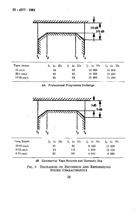
TAPE SPEED fi in Hz fi in Hz f3 in Hz f4 in Hz
76 cm/s 40 63 10 000 14 000 38.1 cm/s 40 63 10 000 14 000 19.05 cm/s 40 63 10 000 14 000
4A Professional Programme Exchange
TAPE SPEED fi in Hz fi in Hz fa in Hz fa in Hz
19.05 cm/s 40 80 8 000 14 000 9.53 cm/s 63 125 6 300 12 500 476 cm/s 80 160 4 000 8 000
48 Commercial Tape Records and Domestic Use
FIG. 4 TOLERANCES ON RECORDING AND REPRODUCING SYSTEM CHARACTERISTICS
18
IS : 4377 - 1981
10.2.1.3 At least the the reference number of the programme and the reel number shall be given either on the leader or on the spool. If infor- mation is carried on tlhe leader it should be on the side continuous with the non-recorded side of the tape.
NOTE - A label giving the following informatlon may accompany each reel:
a) Producing organization;
b) Programme title;
c) Reel number;
d) Total number of reels;
e) Reference number of programme;
f) Total playing time of programme;
g) Speed of tape ( marked as prominently as possible );
h) Type of recording, for example, monophonic, stereophonic;
j) Information about maximum recorded level;
k) Noise reduction system, if any;
m) Number and use of tracks; and
n) Replay time constants.
10.2.2 Cassette --The following information may be given on the cassettes:
a) Title; b) Catalogue number; c) Type of recording if relevant, for example, monophonic, stereo-
phonic and others; d) Side identification, if relevant; and e) Noise reduction system, if any.
10.2.3 For Domestic Use
10.2.3.1 Reel-to-red- There shall be a leader tape of non-magnetic material for identification, having a colour different from that of the tape and at least 0.5 m long at the beginning of each recorded tape.
The following information may be given on the tape leader, the reel or the container of the reel:
4 b) C> 4 e> f) g>
Number of tracks; Type of recording, for example, monophonic, stereophonic; Tape speed; Title; Catalogue number; Side identification; and Noise reduction system, if any.
19

IS : 4377 - 1981
10.2.3.2 Cassette - Provision of 10.2.2 shall apply.
10.3 Colour of Leader Tapes
10.3.1 For Recorded Tapes
10.3.1.1 For professional programme exchange: reel-to-reel - Bohr identification strips at the beginning of the reel are not specified, but it is recommended that the identification strip at the end of the reel should be red.
10.3.1.2 The domestic use: reel-to-reel - Provisions of 10.3.1.1 shall apply.
20