Embed Size (px)
Citation preview

Disclosure to Promote the Right To Information
Whereas the Parliament of India has set out to provide a practical regime of right to information for citizens to secure access to information under the control of public authorities, in order to promote transparency and accountability in the working of every public authority, and whereas the attached publication of the Bureau of Indian Standards is of particular interest to the public, particularly disadvantaged communities and those engaged in the pursuit of education and knowledge, the attached public safety standard is made available to promote the timely dissemination of this information in an accurate manner to the public.
इंटरनेट मानक
“!ान $ एक न' भारत का +नम-ण”Satyanarayan Gangaram Pitroda
“Invent a New India Using Knowledge”
“प0रा1 को छोड न' 5 तरफ”Jawaharlal Nehru
“Step Out From the Old to the New”
“जान1 का अ+धकार, जी1 का अ+धकार”Mazdoor Kisan Shakti Sangathan
“The Right to Information, The Right to Live”
“!ान एक ऐसा खजाना > जो कभी च0राया नहB जा सकता है”Bhartṛhari—Nītiśatakam
“Knowledge is such a treasure which cannot be stolen”
“Invent a New India Using Knowledge”
है”ह”ह
IS 3348 (1965): Specification for fibre insulation boards[CED 20: Wood and other Lignocellulosic products]

IS : 3348 - 1965
Indian Standard Reaffirmed 2009
SPECIFICATION FORFIBRE INSULATION BOARDS
( Third Reprint DECEMBER 1996)
UDC 691.147
Copyright 1965
BUREA U OF INDIAN STANDARDSMANAK BHAVAN, 9 BAHADUR SHAH ZAFAR MARG
NEW DELHI 11 0002
December 1965
IS z 33-i8 • 1965
Indian StandardSPECIFICATION FOR
FIBRE INSULATION BOARDS
Wood Products Sectional Committee, BDC 20
Chairman
DR. D. NARAYANAMURTI
Members
Representing
Indian Plywood Industries Research Association,Bangalore
Forest Research Institute & Colleges, Dehra DunJay Shree Tea & Industries Ltd., Calcutta
The Plywood Manufacturers' Association of India,Calcutta
ASSiSTANT DIRECTOR (SPEOIFJ- Railway Board ( Ministry of Railways)CATION), RESEARCH, DESIGNAND STANDARD!! ORGANIZA-TION
SURI P. BARUA Forest Department, Gover nrnen t of AssamDIRECTOR, Scn:N'l'lFW RESI'AROIt Naval Headquarters, Ministry of DefenceSIlRI 1\1. J. GR1FPlTHB Indian Tea Association, Calcutta
SHRI A J. CAMERON ( Alternate )OR. JOSEPH GEORGE Central Building Research Institute ( CSIR ),
RoorkeeSURI Sutv A MOHAN SINGH ( Alternate )
SURI A. K. KADERKUTTY The Western India Plywoods Ltd., BaliapatamSRRI N. S. KAIKtNI Forest Department, Government of Mysore
SHRI K. K. NAlDU ( Alternate)SURI R. C. KAU!lRIKSURI G. L. KEDIA
SIlRI K. K. KELA ( Allemale )SUBI B. K. KUAl'l'AN
SKRI G. L. KI!lDlA ( Altemau )SHRI K. S. LAULY Southern India Plywood Manufacturers' Association,
CalicutSIlRI V. J. NEDUNGADI (Alternate )
SIIRI J. S. MATHARU Directorate GeneralofTechnical DevelopmentDR. A. N. NAYE:R Defence Production (DGI ), Ministry of Defence
SaRI R. N. VAW'" A ( Alternate)PRESIDEN'l' Forest Research Institute & Colleges, Dehra DunSaRI RAllINDElt SUWIl National Buildings Organization ( Ministry of Works
& Housing)ASSHITANT DIRECTUR (T) ( Alternate )
SllRI S. RHlAMRITHAM Directorate General of Civil AVIation (Mmlstry ofTransport)
SURf N. K. SHARMA Forest Department, Govcrnmcnt of Madhya PradeshLT-CoL G. B. SINGH Engineer-in-Chief's Branch, Army Headquarters
SURI VASANTHA RAo (Allemate)
( Con/muedonpage2 )
BUREAU OF INDIAN STANDARDSMANAK BHAVAN, 9 BAIIADUR SHAH ZAFAR MARG
NEW DELHI 110002

IS I 3348 .. 1965
( Continrudjrom /JaIe t )
Members R,p,euntlng
SHRI A. V SUBBA RAo Assam Railways and Tradmg Co Ltd., MargherrtaSaRI P. K. CBOUTBOY( Alternat« )
<'UPERINTENDING SUBVEYOB OJ' Central Public Works Departme-ntWORKS
Saar M. SWARUP Paharpur Timbers Private Ltd., Calcutta~DRI H. THOMSON Plywood Products, Sitapur
SHRI G W. M. WBITTLIl: (Altmlate)On H C VIBVESVAB.AYA, Director, lSI ( Ex-offiCIo Memb,,)
Deputy Director ( Civil Eng)
Stcrdary
SHBIS.P.RAMAN
Assistant Director (CIVil Eng). lSI
Fibre Building Boards Subcommittee, BOC 20: 6
ConvenerDR D NARAYANAIlURTI Indian Plywood Industries Research ASSOCiation,
Bangalorc
~HRI SHIVA MOHAN SINna~HRI K. S. LAULYSHRI j. :-'. MATDARUDR A. N. NAYER~HRI A K RAMAOHANDRANSHRI H. [HOMSON
Mmzbers
ASSISTANT DIRECTOR (SPICCIJ'I- Railway Board (MinIStry of Ratlways )OATlON), RrasEAROR. DESIGNAND STANDARDB ORGANIZA-TION
ASSISTANT DIRBCTORSTAND-ARDS ( CARRIAGE) t Altemate )
'iHRI N. C. JAIN Forest Research Insutute & Colleges, Dehra Dun~aRI (; R. JOLLY AmI Hardboards Ltd, BombayDR JOSEPH GEOROI': Central BUilding Research Insntute ( C5IR),
Roorkee( Alternate )
Indian Plywood Manufacturrng Co Ltd., BombayDirectorate General of Technical DevelopmentDefence Producuon ( DGI), Ministry of Defence'1he Western India Plywood Ltd, BahapatamPlywood Products, Sitapui
AMENDMENT NO. 1 APRIL 1978TO
IS: 3348-1965 SPECIFICATION FORFIBRE INSULATION BOARDS
AlteratloDs
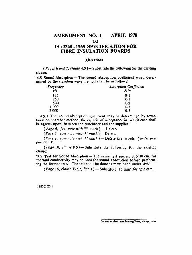
( Pages 6 and 7, clause 4.5 ) - Substitute the following for the existingclause:'4.5 Sound AbsorptioD - The sound absorption coefficient when determined by the standing wave method shall be as follows:
Frequency Absorption Coefficient~s M~
125 0·1250 0.1500 0·2
1000 0·32000 0·5
4.5.1 The sound absorption coefficient may be determined by reverberation chamber method, the criteria of acceptance in which case shallbe agreed upon, between the purchaser and the supplier.'
i Page 6, foot-note with ,t, mark) - Delete.(Page 7, foot-note with '.' mark) - Delete.(Page 8, foot-note with.'>' mark) - Delete the words '( under pre
paration y:(Page 10, clause 9.5) - Substitute the following for the existing
clause:'9.5 Test for Sound Absorption - The same test pieces, 30 x 30 em, forthermal conductivity may be used for sound absorption before performing the former test. The test shall be done as mentioned under 4'5:
(Page 16, clause E-2.2, line 1) -Substitute '15 mm' for '2'2 mm'.
(DOC 20)
Pnnted al New Indll Pnnhna Pre... Khul)a, India
AMENDMENT NO. 2 JUNE 2005TO
IS 3348: 1965 SPECIFICATION FORFIBRE INSULATION BOARDS
( Page 4, clause 3 ) - Substitute the following tor the exisung
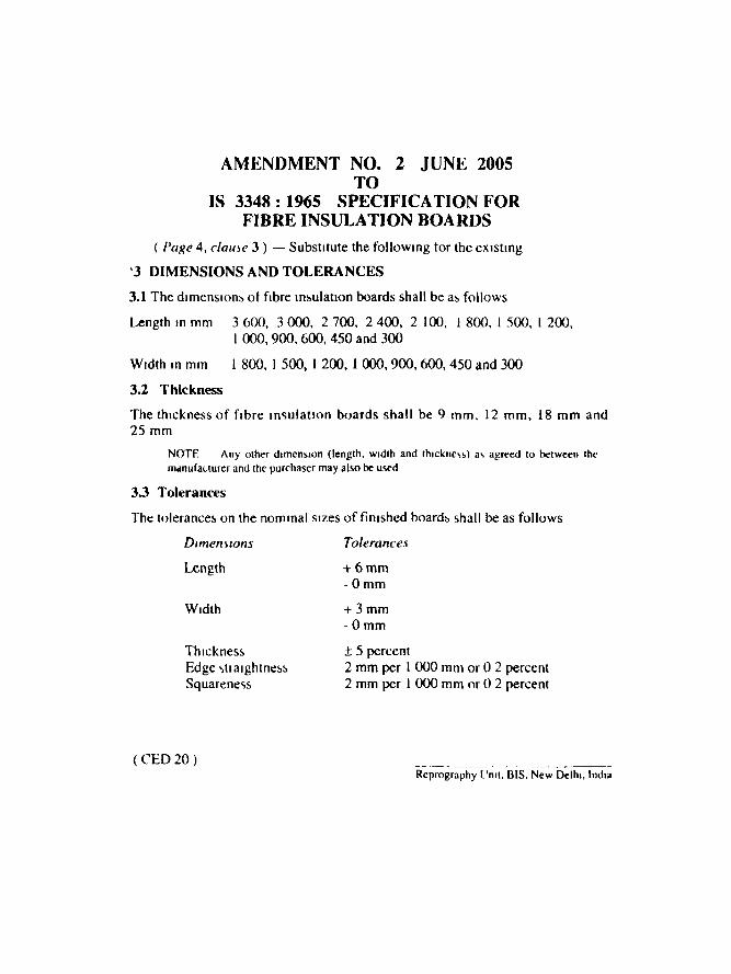
'3 DIMENSIONS AND TOLERANCES
3.1 The dimensions of fibre msulanon boards shall be as follows
Length in mm 3 600. 3 000. 2 700. 2 400. 2 100, I 800, I 500, I 200,1000, 900. 600, 450 and 300
Width rn mm 1 800, I 500, I 200, 1 000,900,600,450 and 300
3.2 Thickness
The thickness of fibre msulauon boards shall be 9 mrn, 12 mrn, 18 mm and25 mm
NOTE - Any other drmensron (length. width and thrckncvs) av agreed to between themanufacturer and the purchaser may also be used
3.3 Tolerances
The tolerances on the nominal srzes of finished boards shall be as follows
Dimensions
Length
ThicknessEdge .,11 arghtnessSquareness
(CED 20)
Tolerances
+6mm-Omm
+3mm-Omm
±5 percent2 mm per I 000 mm or 0 2 percent2 mm per I 000 mm or 0 2 percent
Reprography Unu, B1S. New Deihl, India
rs. 33.· 1965
Indian StandardSPECIFICATION FOR
FIBRE INSULATION BOARDS
o. FOR E W 0 R D
0.1 This Indian Standard was adopted by the Indian Standards Institutionon 17 September 1965, after the draft Iinalized by the Wood ProductsSectional Committee had been approved by the Civil Engineering DivisionCouncil.
0.2 Fibre insulation boards of various types are being- used in increasingquantities as an insulation material and are also linding use as acousticboards This standard is Intended to classify the various types of insulationboards and to lay down the essential requirements for such type of'boardsfor gennal plll poses.
0.3 In the formulation of tlus standard due weightage has been given tointernational co-ordination among the standards and practices prevailingin different countries in addition to relating it to the practices in this fieldin this count. y. This lias been met by basing the standard on the followingpublica tions:
ll-GP-2 Fibreboard; msulaung. Canadian Government Specification'Board .
.lIS A-Sf)O-l-196l Insulation hbreboard«. .lapane,e Standard, Asvonation.
0.4 For the purpOSl' of deciding whether a particular requirement of thisstandard is complied with, the final value, observed or calculated, expressing the revult of a test or analysis, shall be rounded off in accordance withIS : 2-1960*. The number of significant places retained in the rounded offvalue should be the same a, that of the vpccihed value in this standard.
1. SCOPE
1.1 This standard rovers fibre insulating boards made of wood or sugarcane fibre.
·Rul~s for rounding off numerical value. ( "awl).
3
IS: 3348 - 1965
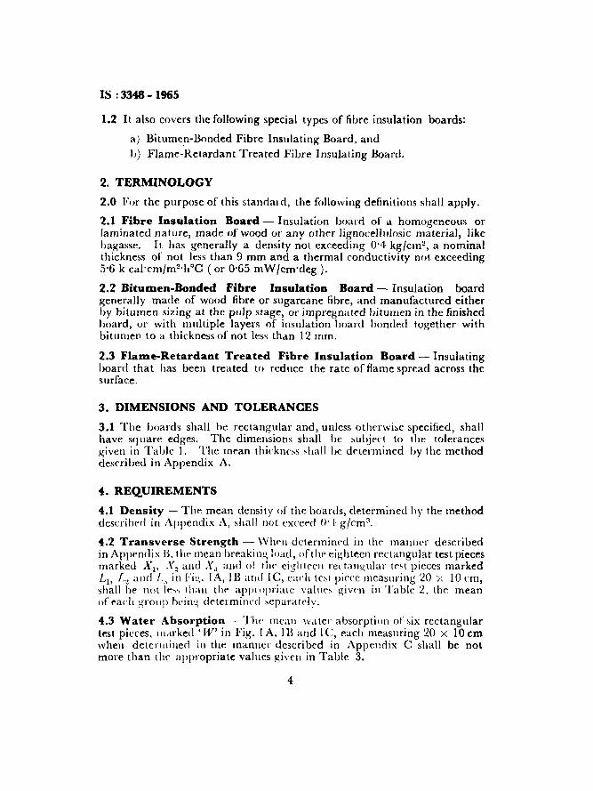
1.2 It also covers the following special types of fibre insulation boards:
a) Bitumen-Bonded Fibre Insulating Board, and1» Flame-Retardant Treated Fibre Insulating Board,
2. TERMINOLOGY
2.0 For the purpose of this standai d, the following definitions shall apply.
2.1 Fibre Insulation Board - Insulation board of a homogeneous orlaminated nature, made of wood or any other lignocellulosic material, likebagasse. It has generally a density not exceeding 0'4 kg{cm2, a nominalthickness of not less than 9 mm and a thermal conductivity not exceeding5'6 k cal'cm{m2'hoC (or 0'65 mW{cm·deg).
2.2 Bitumen-Bonded Fibre Insulation Board - Insulation boardgenerally made of wood fibre or sugarcane fibre, and manufactured eitherby bitumen sizing at the pulp stage, or impregnated bitumen in the finishedboard, or with multiple layers of insulation hoard handed together withbitumen to a thickness of not less than 12 mm.
2.3 Flame-Retardant Treated Fibre Insulation Board - Insulatingboard that has been treated to reduce the rate of flame spread across thesurface.
3. DIMENSIONS AND TOLERANCES
3.1 The boards shall be rectangular and, unless otherwise specified, shallhave sq uare edges. The dimensions shal1 bc subject to the tolerances~iven in Table I. Thc mean thickness shall be determined by the methoddescribed in Appendix A.
4. REQ.UIREMENTS
4.1 Density - The mean density of the boards, determined by the methoddescribed in Appendix A, shall not exceed /1'1 glctn",
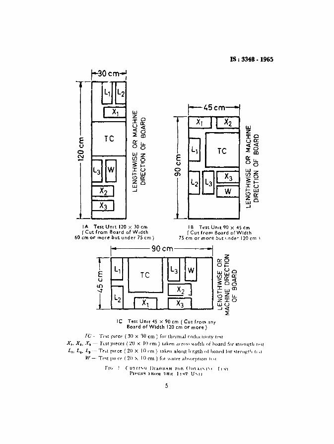
4.2 Transverse Strength - \VIH'1l determined in t lu: manner describedin Appendix B. the mean breaking load, of the' eighteen rectangular test piecesmarked Xl' .\'2 and Xa and 01 thr ei~;hl!'ell rc.tanuular Ipst pieces marked1.1> L, aud I., in hg. lA, IB and IC, each te,1 piece measuring 20 X 10 em,shall be nol le-, rhau t he appi opriatc values giv('n in Table 2, the meanof each group Iwing de-termined scpuratclv.
4.3 Water Absorption - The mean water absorption or six rectangulartest pieces, iuarked 'IV' in Fig. I A, 113 and I C, each measuring 20 X 10 emwhen dete ru iined in the manner described in Appendix C shall be notmore than the appropriate val lies given in Table 3.
4
IS: 3348·1965
W~oIQ:u<{«0
E Te ~CD
Q:LJ..U °0
0 WzN~o-
L) 6 ~i=:ruf-W(!)Q:z-w O
X2 ...J
X3
rXl I X2
~
L, TeE I--u
0~
Bm X3L2~
W
UJZ-0::Co:u<{«0~al
Q:l.J..°0W z~o~i=::cu~w(!)Q:zw O~
IA Test Unll 120 x 30 em( Cut from Board of W,dlh
60 em or more but under 75 em)
IB TeSI Urut 90 X 45 em(Cut from Board of Width
75 em or more but i.nde-' 120 em \
----90cm----
L, Te L3 W~ -- -f-- rnL2 I x, I X3 I
IC Test Unit 45 x 90 em (CUt from anyBoard of Width 120 em or more)
Fe- Test piece (30 X 10 em) for thermal codur uvitv tr-st
X" X•• X. - Fr.st pieces (~O x 10 em) take-n .1< roS' width of hoard for slren~lh tr-st
L"
L,• L. - Tnt pn ce (20 X 10 cm ) take-n along l- ngth of hoard fnr ~tr('ngtll (, ,(
W - Te<t pu ce (2ll A 10 em ) fOl \\ a ter abvorption It vt
fH. I (11111"" DrAOI<AM FOR (llllAI"-'''' II ~l
PIFeR'! } ROM 1 HE I J 'n U" II
5
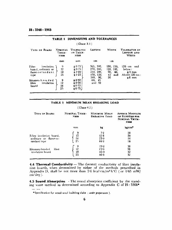
IS: 3348·1965
TABLE 1 DIMENSIONS AND TOLERANCES
( Clause 3.1 )
TYPJ>: or BOARD NOMINAL TOLERANCE LENGTH WIDTH TOLERANCE ONTJlICK- ON THICK- LENGTH AND
NESS NEBS WIDTH
mm mm em cm
Frbrv insulaticn 1 9 t ()'75'\ 365, 300, 180, 150, 120 em andboai d , ordinary or 12 to 7:) I 270, 240, 120, 100, bl'1ow:flame-r eta r dan t 18 t 1'00' 210, 180, 90, 60, :f::3 mmIype ) 25
*''' f150, 120, 45 and Above 120 em:100, 90, 30 ±6 mm
Bitumen-b 0 n de d } 9 :to'50 60, 45fibre insulation 12 to'50 and 30board 18 ::1:0'75 I
25 ::1:0'75)
TABLE 2 MINIMUM MEAN BREAKING LOAD
(Clause 42)
TYPE or BOARD NOMINAL THICK- MINIMUM MEAN ApPROX MODULUSNESS BREAKING LOAD or RUPTUR.E rOR
NOMINAL Tares-NEBS
mm kg kg/em'
{' 7'2 20Fibre insulation board. 12 12'8 20ordinary or lIam..-r e- IH 23'0 16tardant tvpe 2'; 44'0 16
f I~13'0 38
Bitumen-bonded fibre :13'0 38insulation board I 18 45·0 32
L 25 116'0 32
4.4 Thermal Conductivity - The thermal conductivity of fibre insulation boards. when determined by either of the methods prescribed inAppendix D, shall be not more than 5'6 kca!'cm/m:l'hoC (or 0'65 mW/cmdeg ).
4.5 Sound Absorption - The sound absorption coefficient by the standing wave method as determined according to Appendix C of IS : 3308*
·~peeificarion for wood wool building slabs \ under preparatIon ).
IS z 3348 • 1965
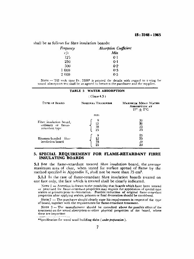
shall be as follows for fibre insulation boards:Frequency Absorption Coefficient
cjs Min125 0'12~ ~l
500 0'21 000 0·32000 0'5
Non; - Till such time IS , 3308· is printed the derails with regard to i -sting' forsound absorptro n tl',1 shall he as agreed to between the purchaser and th e suppl ier.
TABLE 3 WATER ABSORPTION
( Claus, 4.3 )
TYPE 01' BO .... RIl
Fibre insulation hoard,ordinary or Ilarneretardant lype
Bitumen-bonded flbll'insulation board
NOMINAL THICIl:NEII8
mm
( 9
t 121825
r 9
t 121825
MAXIMUM MEAN WATBR
AB80RPTION AT
27° ± z-c
30302525
2525zo20
5. SPECIAL REQUIREMENT FOR FLAME-RETARDANT FIBREINSULATING BOARDS
5.1 For the flame-retardant treated fibre insulation board, the averagemaximum area of char, when tested for surface spread of flame by themethod specified in Appendix E, shall not be more than 75 em",
5.1.1 In the case of flame-retardant fibre insulation boards treated onone face only, the face which is treated shall be clearly indicated.
Non: 1 - Attention is drawn to the possibility that boards which have been treatedor processed for flame-retardant properties may require the application of special typesealers or primers prior to decoration, Possible reduction of original flame-retardantproperties after applying sealers, primers or final decoration should be considered,
NOTE 2 - The purchaser should clearly state his requirements in respect of the typeof board, together with the requirements for flame-retardant treatment.
NOTE 3 - The manufacturer should be consulted about the possible effect or thetreatment on the sound absorption or other physical properties of the board, wherethese are important
·Specification for wood wool build ing slabs ( underpreparation ).
7
IS: 3348 -1965
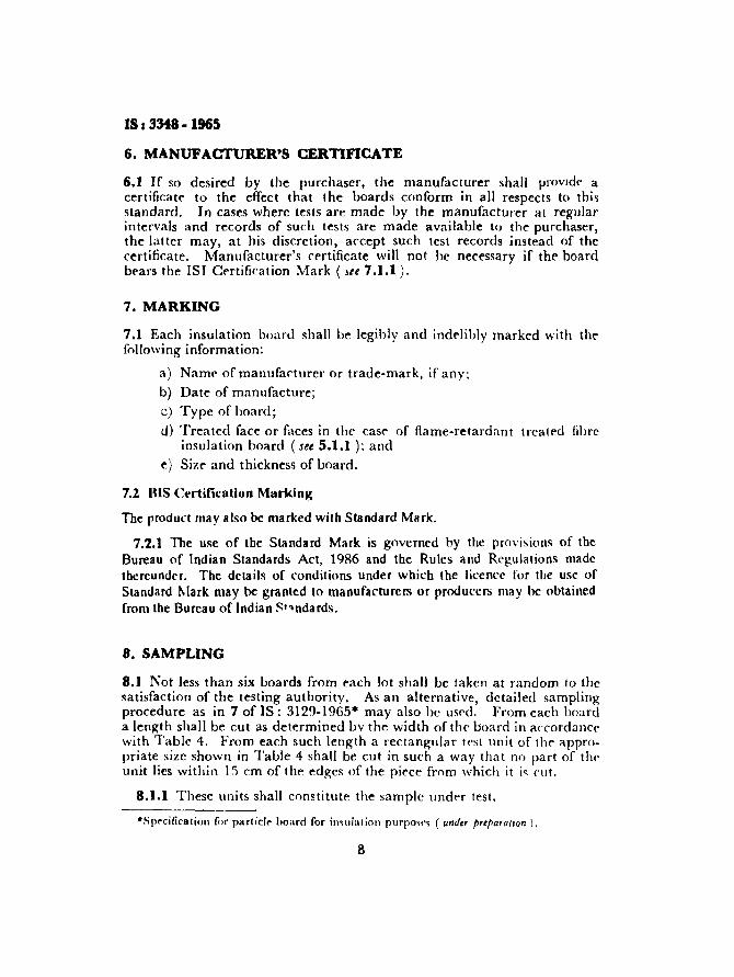
6. MANUFACTURER'S CERTIFICATE
6.1 If so desired by the purchaser, the manufacturer shall provide acertificate to the effect that the boards conform in all respects to thisstandard. In cases where tests are made by the manufacturer at regularintervals and records of such tests are made available to the purchaser,the latter may, at his discretion, accept such lest records instead of thecertificate. Manufacturer's certificate will not he necessary if the boardbears the lSI Certification Mark (Jet 7.1.1).
7. MARKING
7.1 Each insulation board shall be legibly and indelibly marked with thefollowing information:
a) Name of manufacturer or trade-mark, if any;b) Date of manufacture;c) Type of board;
d) Treated face or faces in the cast" of flame-retardant treated fibreinsulation board (see 5.1.1 ); and
e) SiZ(" and thickness of board.
7.2 DIS Certification Marking
The product may also be marked with Standard Mark.
7.2.1 The use of the Standard Mark is governed by the provisions of theBureau of Indian Standards Act, 1986 and the Rules and Regulations madethereunder. The details of conditions under which the licence for the use ofStandard Mark may be granted to manufacturers or producers may be obtainedfrom the Bureau of Indian ~"'ndards.
8. SAMPLING
8.1 Not less than six boards from each lot shall be taken at random to thesatisfaction of the testing authority. As an alternative, detailed samplingprocedure as in 7 of IS: 3129-1965$ may also he used. From each boarda length shall be cut as determined bv the width of the board in accordancewith Table 4. From each such length a rectangular test unit of the appropriate size shown in Table 4 shall be cut in such a way that no part of t hrunit lies within 15 em of the edges of the piece from which it i~ cut.
8.1.1 These units shall constitute the sample under test.
·Sp~cificalion fi,r particle hoard for insulat ion purposes ( under ",epa,a/ron ).
8
IS: 3348 ·1965
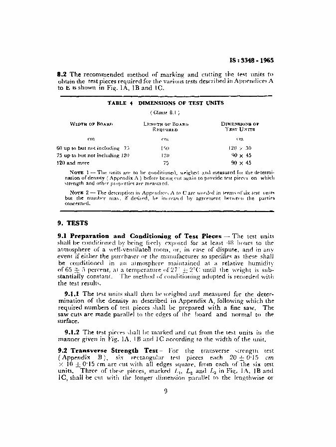
8.2 The recommended method of marking and cutting the test units toobtain the test pieces required for the various tests descri bed in Appendices Ato E IS shown in Fig. \ A, \ Band \ C.
TABLE" DIMENSIONS OF TEST UNITS
(ClallIt 8.1 )
WIDTH OF BOARIl
em
60 up to bUL not including 7 j
75 up to bur not incllldinl'( 120
120 and more
LRNlITH OF BUARD
REQ1'IRED
ern
DIMENSIONS OJ'TEST UNITS
em
120 :.-' 30
YO X 45
90 X 45
NOTE I - The units an' La he conditioned, \\'~i~h{"d and measured fm Lhe de terrnination of dcnsrty ( Appendix A ) before be mg CUi again [0 provide test pieces on whichstre-ngth and alha propnlic, arr rneavur cd.
NOTE 2 - The descrrption in App"lJ(J'CI>, A to Care wOl<kd in term, of six lest un nsbUL the number rnav , if desired, be illl rI'3" d hv aRrcrlllent betwee-n the partiesconcerne-d.
9. TESTS
9.1 Preparation and Conditioning of Test Pieces - The test unitsshall be conditinur-d by bt'ing fieely exposed for at least ·tR hours to theatmosphere of a well-ventilated room, or, in case of dispute, and in anyevent if either the purchaser or the manufacturer 50 specifies as these shallbe conditioned in an ntrnosphcrr- maintained at a relative humidityof 65 :1:: 5 percent, at a temperature of 27" :1:.: 2°(; until the weight is substantially constant. Tht' method of conditioning adopted is recorded withthe test results.
9.1.1 The test units shall then be weighed and measured for the determination of the density as described in Appendix A, following which therequired numbers of test pieces "hall be prepared with a fine saw. Thesaw cuts are made parallel to the edges of the hoard and normal to thesurface.
9.1.2 The test pieces <lia ll lie marked and cut from the lest units in themanner given in Fig. l A, \ B and l C according 10 the width of the unit.
9.2 Transverse Strength Test - For the transverse strengtn test(Appt:ndix B), six rectangular t('~t pieces each 20 ± O'IS emX \0 ± 0'\5 em are cut with all edges square, from each of the six testunits. Three of thcs« pieces, marked L t , L 2 and L 3 in Fig. \ A, \BandIe, shall be cut with the longer dimension parallel to the lengthwise or
9
IS: 3348 -1965
machine direction of the board and three, marked Xl> X2 and X3in Fig. IA, IB and IC at right angles to this direction.
9.3 Water Absorption Test _. For the water absorption test (Appendix C), one further test piece marked 'w' in Fig. lA, IB and Ie,20 :1: O'I5 cm x IO ± 0'15 em, shall be prepared in the same manner, asdescribed in 9.2, from each of the six test units. The edges of these testpieces are smoothed with sand-paper, but not sealed.
9.4 Thermal Conductivity Test - For the thermal conductivity test(Appendix D), a rest piece marked 'TC' in Fig. IA, IB and Ie.30 X 30 em, shall be prepared frorn each of four test units.
9.5 Test for Sound Absorption -.- This shall be done in accordancewith Appendix C of IS: 3308.... The same test pieces, 30 X 30 em, forthermal conductivity test may he used for sound absorption before performing the former test.
9.6 Test for Flame Spread .- Test for flame spread shall be done inaccordance with the method specified in Appendix E. The specimenshall be 30 X 30 ern size and not It"'is than three test specimens shall hrtested for this purpme.
APPENDIX A
( Clauses 3.1, 4.1, 8.2 and 9.1.1 )
DETERMINATION OF THICKNESS AND DENSITY
A-I. DETERMINATION OF THICKNESS
A-t.t The length, width and weight of each of the six test units shall bedetermined, the length and width to an accuracy of ]'5 mm and theweight to an accuracy of :to'S percent.
A-1.2 The thickness of each unit shall be measured to an accuracy ofO'I5 mm at six points representing the points of intersection of the diagonals of the six 20 X 10 em test pieces intended for measurement of thetransverse strength. This may be done after the test unit has been markedfor cutting or after the test pieces have been cut, whichever is more convenient, provided that the material under test is in a properly conditionedstate ( 9.t ) when the measurements are made.
A-1.3 The contacting surfaces of the measuring instrument shall be flatand shall have a diameter of at least 9 mm and care shall be taken that
.Specification for wood wool building slabs ( unde« preparation ).
10
IS t 3348 - 1965
the surfaces of the board are not deformed when the thickness is measured.The mean of the six measurements shall be deemed to be the thickness ofthe test unit.
A-2. DETERMINATION OF DENSITY
A-2.1 The density of each test unit shall be calculated as follows:
when'
Density =
or =
WL x b Y t
1000 WI, Y-b ;" t
g/cm3
W = weight of test unit in g,
L -~ length in r m,
h ,- width in (TTl, and
t = mean thickness iII em.
A-2.1.1 The density of each test unit shall be reported together with theaverage density of all the test units.
APPENDIX B
( Clauses 4.2, 8.2 and 9.2 )
DETERMINATION OF TRANSVERSE STRENGTH
B-O. GENERAL
B-O.l Thirty-six test pieces, each 20 " 10 em, pI eparcd in accordancewith 9.1, shall be used for deterrnininz the transverse strength. The testpieces shall be- all tested with I he same face uppermost.
B-1. PROCEDURE
B-l,l Each test piece' shall he simply supported on hOI izuntal parallelrollers having a diameter of IB to 2: mrn spaced at 15 em centre to centreand free to rotate in ball or roller bearings, The width of the test pieceof bitumen fibre insulation board of thickness IH mrn and above shall be5 em only. The load may then be calculated and corrected to obtain theload for lO-cm width. A load shall then be applied at the centre of thespan along a line parallel to the rollers by means of a bar rounded to a
11

IS: 3348· 1965
radius of 9 to 12 em. The load is increased at a rate such that the appropriate minimum breaking load, stated in Table 2, is reached in not lessthan haifa minute and not more than four minutes from the commencement of its application.
8-1.1.1 The following information shall he reported:
a) The failing load and modulus of rupture of each test piece;
b) The mean failing load and mean modulus of rupture for theeighteen test piece-, marked Ll , L 2 and [,3; and
r) The mean failing load and mean modulus of rupture for theeighteen test pieces marked Xl' X 2 and X 3 .
'\[OTE - Modulus of rupture may be calculated from this information as follows:
I 3 ~t IModulus of rupture, kg/em = -2bii'
wher>
W -- fadinp; load in kg:,
I - il'n,~lh of span ill em.
b ~, width oflt'st piece in em, and
d ,- thickness of test piece in em.
APPENDIX C
( Clauses 4.3, 8.2 and 9.3 )
DETERMINATION OF WATER ABSORPTION
C-O. GENERAL
CO.l Six test pieces each 20 X 10 em, prepared in accordance with 9.1,shall be used in determining the water absorption.
C-I. PROCEDURE
C-l.l Each tevt piece shall be weighed to an accuracy of ±O'5 g. It shallthen be immersed in flesh, clean water, having a pH value of between 6'5and 7''j and a temperature of 27° ± 2°C, the water being renewed beforeeach test. The tt'~( pieces shall he immersed in such a way that they arehorizontal, clear of the bottom of the tank, and covered by approximately25-mm layer of water, After two hours of immersion. they shall be withdrawn from water and after wiping off any exce-s of water with a dampdoth, each test piece shall he reweighed \0 an accuracy of +0':1 !!;.
12

IS: 3348 - 1965
C-l.l.l The following information shall be reported:a) The water absorbed by each test piece expressed as a percentage
of its weight before immersion, andb) The mean percentage water absorption of the six test pieces.
APPENDIX D( Clauses 4.4, 8.2 and 9.4 )
METHOD 0)<' TEST FOR THERMAL CONDUCTIVITY
0-0. GENERAL
0-0.1 Either of the methods covered in 0-2 and D-3 may be used fordetermining thermal conductivity,
D-1. PREPARATION OF TEST SPECIMENS
D-1.1 One test piece from each sample shall be etlt away limn the end o~'
the sample by 15 em unless the size of the board is such that the samplehas to be cut nearer to the edge. The size of the sample shall be30 X 30 em and the full thickness of the board.
0-1.2 Measurement of Thickness of Spec:iJnens - The thickness ofspecimen shall be measured at a number of places for finding the average.The thickness may also he found hy measuring the area of the specimenand also the volume of the specimen after the test by immersing in water.
0-1.3 Test specimens shall be conditioned to a uniform moisture accordingto 3.2.1 ofIS: 23RO-1963-,
)),1.4 The minimum thickness of the board in between the plates shall be24 mm, In case the thickness of the board is less than this, two or threeboards shall be used-together, placed one over the other, to make thethickness minimum 24 mm.
D-2. METHOD I (GUARDED HOT-PLATE METHOD USINGTWO SLABS)
0-2.1 This shall be done using the apparatus and following the procedurespecified in IS: 33461' maintaining the temperatures of the hot-plateand cold-plate respectively at 30" and 25uC.
NOTE -- Till IS: 33fbt is pubhshed, the method shall be subject lu agreement between the concerned parties.
.Method of test for wood particle boards and board, from other lignocellulosicmaterials.
tMethod for the determination of thermal conductivity of thermal Insulating material,( two-slab, guarded hot-plate method) ( under preparallon).
13

IS t 3348·1965
0-2.2 Calculation - The test area shall be calculated from the centre ofone separation to the centre of the other separation across the centralsurface of the plate. The thermal conductivity shall then be c<lllUlcltedfrom t he following fOI mula:
q/.LK= ----- --
~1 ( t. - (2)
where
K = thermal conductivrty in keal'cm!em2'h oC,q ~= time ra te of heat flow area rA ( kcal fh ) J,L = length of path of heat flow (thickness of specimen)
in ern,A = area normal to heat flow ( m2 ),
11 -=: temperature of hot surface ( °C), and12 -= temperature of cold ~UI fdl e ( nc ).
0-3. METHOD II (GUARDED HOT-PLATE METHOD USINGSINGLE SLAB)
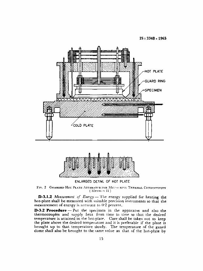
0-3.1 Apparatus - The apparatus shall be cI,> ,hOWIl 1Il FH~. 2. It shallconsist of the cold-plate on which specimen to be- tested IS placed and ahot-plate of about 10 em diameter. The guard I ing shall be shaped likea dome and shall be maintained at the same temper ature as the hot-plate.The "pace between the upper surface of the hot-plate (which is. alsoinsulat ed ) .md inner surface of the top of the guard dome being filledwith air. A bell jar of suitable size shall alvo be available to enclosethe hot-plate, guard dome and the specimen whenever required, so that bymeans of suitable hot solutions placed imide the bell j.u , it will be possibleto maintain any humidity corresponding to the moisture content of thespecimen. The hot-plate shaH be made of copper.
0-3.1.1 Measurement of Temperature ~ The hot-plate temperature shallbe measured with the three thermocouples, one embodied in the centre ofthe plate and the other two on the points on either side of the centre on adiameter. The guard dome temperature shall be measured at three pointsat the apices of an equilateral triangle, two of these by means of thermocouples and the third with a thermometer thus including a check on themeasurement. The cold-plate temperature shall be likewise measured bymeans of suitably located thermocouples.
0-3.1.1.1 For the temperature measurements, obli.erated soft solderedmanganin constantan thermocouples (0'3 mm diameter) shall be used.The measurement of temperature shall be accurate to 0'01 "C,
IS: 3348 - 1965
COLD PLATE
GUARD RING
SPECIMEN
ENLARGED DETAIL OF HOT PLATE
FIG. 2 GUARDED HOT PLATI~ AI'I'AHATt'S FOR MF..' -1 ruxo THERMAL CONDUCTIVITY( t\1F.TH(,T) II)
D-3.1.2 Measurement of ETlerg)' - The energy supplied for heating thehot-plate shall be measured with suitable precision instruments so that themeasurement of energy is accurate to 0'2 percent.
0.3.2 Procedure - Put the specimen in the apparatus and also thethermocouples and supply heat (rom time to time so that the desiredtemperature is attained in the hot-plate. Care shall he taken not to keepthe plate above the desired temperature and it is preferable if the plate isbrought up to that temperature slowly. The temperature of the guarddome shall also be brought to the same value as that of the hot-plate by
15
IS &3348· 1965
adjustment of the current in its heating coil. The apparatus shall then beleft undisturbed with a constant energy input for some time. Readmgsshall be taken for temperature, current and energy at every 15 mmutes orhalf-an-hour tiJl after about two hours when they become constant.
D-3.3 CalculatioD - The thermal conductivity shall be calculated in thesame manner as in D-2.2.
APPENDIX E
( Clauses 5.1, 8.2 and 9.6 )
METHOD OF TEST FOR SURFACE SPREAD OF FLAME
E-1. SCOPE
£-1.1 This method COhrs inclrned panel flame tests on insulauon boardto determine the area of char of the finished surface and duration offlaming.
£-2. APPARATUS AND MATERIALS
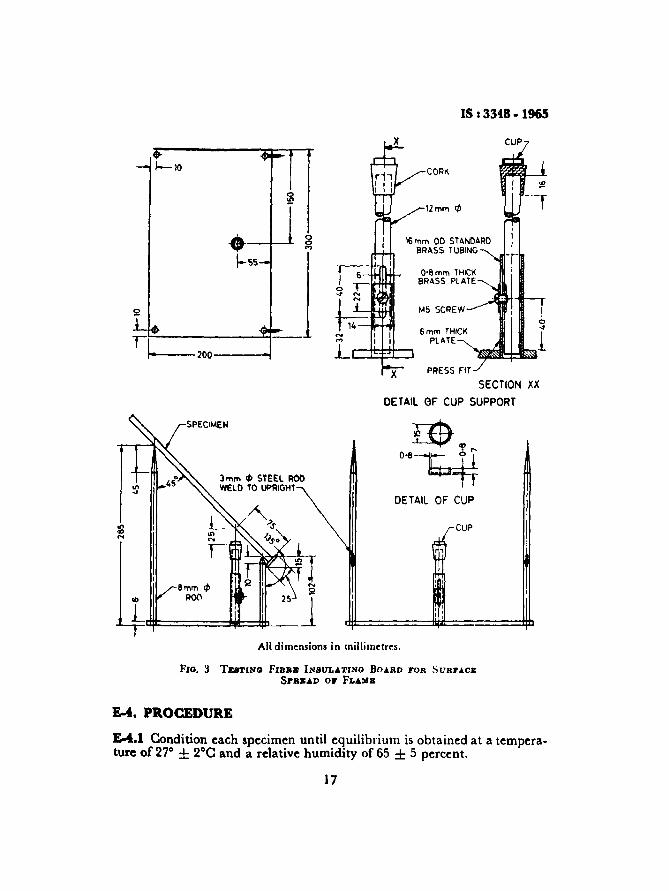
E-2.1 Specimen Support~ Suitable means shall be provided for supporting the specimen during the test at an angle of 45°; with the upper andlower edges of the plane of SUppOlt being horizontal. This may be accomplished by resting the specimen on four points; but it is necessary, whatevermethod of support be employed, that (a) the central portion cf thespecimen shall not be shielded hom the flame, (b) the supports shall notprevent access of air for combustion, and (c) the apparatus shall be suchthat the progress of the test can be observed, A suitable apparatus is shownin Fig. 3.
E-2.2 Flame Source - A flat bottomed cup of ~'2 mm in internal diameter and 7 mm in depth shall he placed on a support composed ofcorkboard. The cup shall be made of sheet iron about 0'8 mm thick. Itshall be supported so that the centre of its base is 25 mm vertically belowa point on the lower sll~face of the test sp~ciIl!en, 75 mm from its lowerhorizontal edge, and midway between the inclined edges.
£-2.3 Alcohol-Absolute ethyl alcohol conforming to IS :321-1964*.
E-3. TEST SPECIMENS
£-3.1 Three 30 X 30 ern specimens, one each from the sample from threeboards, shall be tested .
• Specification for absolute alcohol (rtt istd).
16
IS I 3348. 1965
CORK
PRESS FIT
6mm THICKPLATE
M5 SCREW
0'8mm THICKBRASS PLATE
16mm 00 STANDARDBRASS TUBING
x
og.--+--'\-55
1~'--__ 200 -i
SECTION XX
DETAIL OF CUP SUPPORT
co
.L8mm q,
ROO
3mm Ij) STEEL ROOWELD TO uPRIGHT
DETAIL OF CUP
CUP
: '
, ', :
All dimensions in millimetres.
11, 0 . 3 TESTINO FIBS. INSUL...TINO BOARD FOR SUR7...CJ;Sra.... v OJ' FL...M.
E-4.PROCEDURE
!:-t.l Condition each specimen until equilibrium is obtained at a temperature of 27° ± 2°C and a relative humidity of 65 ± 5 percent.
17

IS I 3348 - 1965
E-4.2 Place the specimen on the test apparatus. Place I ml of absoluteethyl alcohol in the cup from a suitable pipette or other means and Ignite( with the test specimen in place) by a small gas or oil jet or other suitable small source of heat, which shall be removed as soon as the alcohol islighted. The cup shall be at room temperature before each test. The testshall be made in a draft-free room or enclosure with a subdued light.
&4.3 One minute after the fuel has been exhausted, extinguish any flameand glow on the specimen, and determine the area of char. If the durationof flaming is less than I min, extinguish any smoldering, and measure thearea of char. Determine the area of char by cutting slots approximatelyalong the major and minor axes of the elliptical char area to a depthsufficient to expose the board structure below the coating. Determine thelength of these axes by taking the terminal of each line end as that pointwhere a definite charring or decomposition of the fibre structure has firsttaken place.
E-5. CALCULATION AND REPORT
E-S.l Using the major and minor axes, a and b, of the area of char determined in accordance with E.4.3 as those of a true ellipse, calculate thearea of char as follows:
7t abArea of char = T
E-5.2 Report the area of char and the duration of flaming taking theaverage of the three specimens as the average of the lot.
18

BUREAU OF INDIAN STANDARDS
Heedquat1Wa:Manak Bhavan. 9 Bahadur Shah Zalar Marg, NEW DELHI 110002Telephones 3230131. 3238375,3239402Fax 91 11 3234062.91 11 3239399
323635
550 1348
8394955
5&4021
403627
210141
8-288801
8-71199El
541137
20 1083
372925
2168 76
238923
TelegrB1T18 Manaksanslha(Common toall Ofllces)
Telephone
8-nOO32c."trI/I LIIbotwtory:Plot No 2019. Site IV, Sahlbabad,~ Area, Sahlbabad 201010
RegloMl Ottrc.:Central Manak Bhavan. 9 Bahadur Shah lafar Marg. NEW DELHI 110002 323 7617
·Eastern 1/14 CIT Scheme VII M. VI P Road. Manlktola, CALCUTTA 700054 3378682
Northern SCO 335-336, Sector 34-A. CHANDIGARH 160022 60 38 43
Southern CIT Campus. IV Cross Road, MADRAS 600113 235 23 15
twestern Manakalaya, E9. Behind Maro! Telephone Exchange. AnttlerI (East), 832 92 95
MUMBAI 400093
Branch Offlcee:
'Pushpak'. Nurmoharned Shaikh Marg, Khanpur, AHMEDABAD 380001
tpeenya Industl'lal Area, 1st Stage. BangaJor&-llImkur Road,
BAN GALORE 560058
Gangolrl Complex, 5th Floor. Bhadbhada Road. TT Nagar. BHOPAL 462"')3
Plot No 62-63, Unit VI, Ganga Nagar. BHUBAl"C:SHWAA 751001
Kal8lkathll' Buildings, 670 Avlnashl Road. CO:~BATORE 641037
Plot No 43 <:.....'1)1' 16 A. Mathura Road, FARIDABAD 121001
Savltrl Complex. 116 G T Road. GHAZIABAD 201001
53/5 Ward No 29. R G Barua Road. 5th By-lane, GUWAHATI 781003
5-8-56C, L N Gupta Marg. NampaJly Station Road. HYDERABAD 500001
E-52. ChltaranJ8ll Marg, e-Scheme. JAIPUR 302001
117/418 B. Sarvodaya Nagar. KANPUR 208005
Seth Bhavan.2nd Floor, Behind LeeIa CInema, Naval Kishore Road.
LUCKNOW 226001
Patllputra Industrial Estate. PATNA 800013 26 23 05
TC No 1411421. University PO Palayam. THIRUVANANTHAPURAM 695034 62117
In8pectlon omc. (With Sale PoInt)
Pushpanjall. 1st Floor. 205-A, West HIgl Court Road, Shankar Nagar Square, 52 51 71NAGPUR 440010
Instltutlon of Engineers (Inda) Bulking, 1332 Shlvajl Nagar. PUNE 411005
·Sales Olftce Is at 5 Chowrlnghee Approach. PO Prtncep Street,
CALCUTTA "00072 '
tsales Office Is at Novelty Chambers. Grant Road. MUMBAI 400007
~a1es Otftce Is at 'F' Block, Unity Building. Narashlmaraja Square.BANGALORE 560002
271065
3096528
22239 '
Printed at New India Printing Pr•••• Khurja, India
![Undulators at PETRA: Experience and Perspectives · M. Tischer | 3-Way Meeting, 01.08.2013 | Page 3 . U29_5m U29 U32 U23 UE65 * U19 U32_10m Minimum magnetic gap [mm] 9.5 9.5 9.5 9.5](https://img.pdfslide.us/doc/110x75/60b1b5b57fbc0351f21d0761/undulators-at-petra-experience-and-perspectives-m-tischer-3-way-meeting-01082013.jpg)