Embed Size (px)
Citation preview

Disclosure to Promote the Right To Information
Whereas the Parliament of India has set out to provide a practical regime of right to information for citizens to secure access to information under the control of public authorities, in order to promote transparency and accountability in the working of every public authority, and whereas the attached publication of the Bureau of Indian Standards is of particular interest to the public, particularly disadvantaged communities and those engaged in the pursuit of education and knowledge, the attached public safety standard is made available to promote the timely dissemination of this information in an accurate manner to the public.
इंटरनेट मानक
“!ान $ एक न' भारत का +नम-ण”Satyanarayan Gangaram Pitroda
“Invent a New India Using Knowledge”
“प0रा1 को छोड न' 5 तरफ”Jawaharlal Nehru
“Step Out From the Old to the New”
“जान1 का अ+धकार, जी1 का अ+धकार”Mazdoor Kisan Shakti Sangathan
“The Right to Information, The Right to Live”
“!ान एक ऐसा खजाना > जो कभी च0राया नहB जा सकता है”Bhartṛhari—Nītiśatakam
“Knowledge is such a treasure which cannot be stolen”
“Invent a New India Using Knowledge”
है”ह”ह
IS 1795 (1982): Pillar Taps for Water Supply Purposes [CED3: Sanitary Appliances and Water Fittings]

IS : 1795 - 198i
Indian Standard SPECIFICATION FOR
PILLAR TAPS FOR WATER SUPPLY PURPOSES
( Second Revision )
Sanitary Appliances and Water Fittings Sectional Committee, BDC 3
Cfiairman Representing
SARI K. D. MULEKAR Municipal Corporation of Greater Bombay, Bombay
Members
DEPUTY HYDRAULIC ENGINEER ( Alternate to SERI K. D. MULEKAR)
ADVISER ( PHE ) Central Public Health & Environmental Engineer- ing Organization (Ministry of Works & Hous- ing ), New Delhi
DEPUTY ADVISER ( PHE ) ( Alternate ) SHRI M. K. RASU Central Glass & Ceramic Research Institute (CSIR),
Calcutta &RI D. S. CRABHAL Directorate General of Technical Development,
New Delhi SH~I T. RAMASUBRAMANIAN ( Alternate)
SHRI S. P. CHAKRABARTI Central Building Research Institute ( CSIR), Roorkee
SHI~I S. K. SHARMA ( Alternate ) CI~~EF ENGINEER Public Health Engineering Department, Govern-
ment of Kerala, Trivendrum SHRI K. RAMACRANDRAN ( Alternate )
CHIEF ENGINEER UP Jai Nigam, Lucknow SUPERlNTENnING ENQINEER ( Alternaic )
V'SHRI J.D'CRUZ Delhi Municipal Corporation, Delhi Annr, CHIEF ENQINEER ( Altsrnate )
DIRECTOR Bombay Potteries & Tiles Ltd, Bombay SHHI B. R. N. GUPTA Engineer-in-Chief’s Branch, Army Headquarters
SHRI K. V. KRISHNAMURTHY ( Alternate ) SHHI P. JAGANATH RAO EID-Parry.Ltd, Ranipet
SHRI M. MOOSA SULAIMAN (Alternate) SHRI S. R.~KSHIRSAQAR National Environmental Engineering Research
SHRI R. C. REDDY ( Alternate ) .Institute ( CSIR ), Nagpur
SJIRI K.LAKASHMINARAYANAN Hindustan Shipyard Ltd, Visakhapatnam SH~I A. SHARIFF ( Alternate )
( Continued on page 2 )
@ Copvright 1983
INDIAN STANDARDS INSTITUTION ’ This publication is protected under the Indian Copyright Act ( XIV of 1957 ) and reproduction in whole or in part by any means~excgt with written permi&on of the publisher shall be deemed to be an infringement of copyright under the said Act.
IS:1?95-1982
( Confinuedfrom page 1 )
Members Rcpesenting
SHRI ‘E. K. RAMACRANDRAN National Test House, Calcutta SERI S. K. BANERJEE ( Alternate )
SHRI RANJIT SINGH Ministry of Railways ( Railway Board ) DB A. V. R. RAO
SHRI J. SENDUFTA ( Alternate ) National Buildings Qrganization, New Delhi
SHRI R. K. SOMANY Hindustan Sanitaryware & Industries Ltd, Bahadur- garh ( Haryana )
SHRI R. K. SUNDRAM Central Public Works Department, New Delhi SUI~~EYOR OF WORKS I ( NDZ ) ( Alternate )
SHRI T. N. UBOVEJA Directorate General of Supplies & Disposals, New Delhi
SHRI G. RAMAN, Director ( Civ Engg )
Director General, ISI ( Ex-o&a Member )
Secretary
SHRI C. K. BEBARTA Senior Deputy Director ( Civ Engg ), IS1
Domestic and Municipal Water Fittings Subcommittee, BDC 3 : 2
Conuener
SHRI K. D. MULEKAR
Members
Municipal Corporation of Greater Bombay, Bombay
DEPUTY HYDRAULIC ENGINEER ( Ahrnatc to SHRI K. D. MULEKAR )
SHRI YASH RAJ AGCARWAL Goverdhan Das P. A., Calcutta SHRI JOGINDER RAJ AGGARWAL ( Alternaie )
CHIEF ENGrxIEk CHIEF ENQINEER
Bangalore Water Supply Sewerage Board, Bangalore Tam$aE;lu Water Supply & Dramage Board,
CHIEF ENGINEER UP Jal Nigam, Lucknow SUPERINTENDING ENGINEER ( Alternuts )
DIRECTOR Maharashrra Engineering Research Institute, Nasik RESEAROH OFFICER ( Alternate )
SHRI J. D.’ CRUZ SHRI S. A. SWAMY ( Alternate )
Municipal Corporation of Delhi, Delhi
SHRI B. R. N. GUPTA Engineer-in-Chief’s Branch, Army Headquarters SHRI K. V. KRISHNAMURYXY ( AItqrnata )
SERI M. K. JAIN Hind Trading & Manufacturing Co New Delhi
Ltd,
SHRI K. K. JAIN (Alternate ) SERI S. R. KSHIRSAGAR National Environmental Engineering Research
Institute, Nagpur SHRI A. W. DESHPANDE ( Alternate )
SHRI G. A. LUHAR Bombay Metal and Alloy Manufacturing Co Pvt
SHBI K. RAMAOHANDRAN
SERI RANJIT SINGE SERI D. K. SEHGAL
SHRI B. B. SIKKA ( Alternate ) Srrrrr R. K. SOMANY
SHRI T. N. UBOVEJA
Ltd, Bombay Public Health Engineering Department, Government
of Kerala. Trivandrum . . Ministry of Radways, New Delhi Leader Engineering Wdcs, Jullundur
Hindustan Sanitarywarg & Industries Ltd, Bahadurgarh
Directorate General of Supplies & Disposals, New Delhi
2
IS : 1795 - 1982
Indian Standard SPECIFICATION FOR
PILLAR TAPS FOR WATER SUPPLY PURPOSES
t Second Revision )
0. FORE WORD
0.1 This Indian Standard ( Second Indian Standards Institution on 30
Revision ) was adopted by the November 1982, after the draft
finalized by the Sanitary Appliances and Water Fittings Sectional Committee had been approved by the Civil Engineering Division Council.
0.2 This-standard which, was first published in 1961, gave guidance to manufacturers for producing pillar taps of high quality and interchange- ability suitable for wash banns. In the first revision in 1974, the require- ments of 25 mm size pillar taps were deleted as they are not in common use, This revision of the standard has been taken up to incorporate further improvements found necessary in the light of the usage of the same since its publication, These include modifications relating to the requirements of material and dimensions of various components of pillar tap.
0.3 For the purpose of deciding whether a particular requirement of this standard is complied with, the final value, observed or calculated, expressing the result of a test or analysis, shall be rounded off in accord- ance with IS : 2-1960”. The number of significant places retained in the rounded off value should be the same as that of the specified value in this standard.
1. SCOPE
1.1 This standard lays down requirements regarding material, manufacture and workmanship, construction, finish and testing of pillar taps. -
*Rules for rounding off numerical values ( revised ).
3
IS : 1795 ; 1982
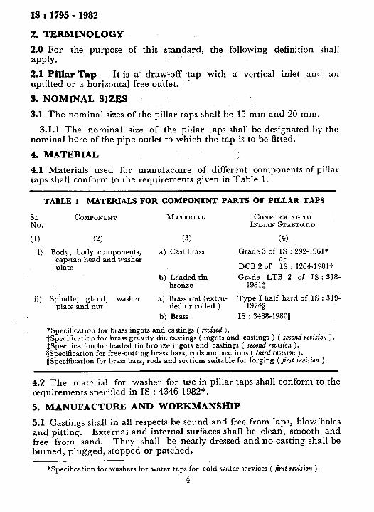
2. TERMINOLOGY
2.0 For the purpose of this standard, the following definition shall
apply. . -
2.1 Pillar Tap - It is a* draw-off tap with a vertical inlet and an uptilted or a horizontal free outlet.
3. NOMINAL SIZES
3.1 The nominal sizes of the pillar taps shall be 15 mm and 20 mm.
3.1.1 The nominal size of the pillar taps shall be designated by the nominal bore of the pipe outlet to which the tap is to be fitted.
4. MATERIAL
4.1 Materials used for manufacture of different components of pillar taps shall conform to the requirements given in Table 1.
TABLE 1 MATERIALS FOR COMPONENT PARTS OF PILLAR TAPS
SL COMPONENT MATERIAL CONFORMINQTO No. INDIAN STANDAI~D
(1) (2) (33) (4)
i) Body, body components, a) Cast brass Grade 3 of IS : 292-1961* capstan head and washer plate DCB 2 of “I’s : 1264-1981t
b) Leaded tin Grade LTB 2 of IS : 318- bronze 1981$
ii) Spindle, gland, washer a) Brass rod (extru- Type I half hard of IS : 319- plate and nut ded or rolled ) 1974s
b) Brass IS : 3488.19801/
*Specification for brass ingots and castings ( revised ). tSpecification for brass gravity die castings ( ingots and castings ) ( second revision ). JSpecification for leaded tin bronze ingots and castings ( second revision ). SSpecification for free-cutting brass bars, rods and sections ( third revision ). IjSpecification for brass bars, rods and sections suitable for forging (first reuision ).
4.2 The material for washer for use in pillar taps shall conform to the requirements specified in IS : 4346-1982*.
5. MANUFACTURE AND WORKMANSHIP
5.1 Castings shall in all respects be sound and free from laps, blow -holes and pitting. External and internal surfaces shall be clean, smooth and free from sand. They shall be neatly dressed and no casting shall be burned, plugged, stopped or patched.
*Specification for washers for water taps for cold water services (Jirst revision ).
4
IS : 1795 - 1982
5.2 The body, bonnet, spindle and other parts shall be machined true, so that when assembled, the parts shall, be axial, parallel and cylinderical with surfaces smoothly finished.
6. CONSTRUCTION
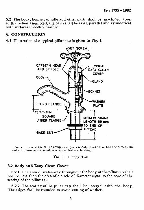
6.1 Illustration of a typical pillartap is given in Fig. 1.
&ET SCREW
CAPSTAN HEA
FIXING FLANGE
UNDER FLANGE MINIMUM SHANK LENGTH 50 mm
-BACK NUT
NOTE - The shape of the component parts is only illustrative but the dimensions and minimum requirements where specified are binding.
FIG. 1 PILLAR TAP
6.2 Body and Easy-Clean Cover
6.2.1 The area of water-way throughout the body of the pillar tap shall not be less than the area of a circle of diameter equal to the bore of the seating of the pillar tap.
6.2.2 The seating of the pillar tap shall be integral with the body. The edges shall be rounded to avoid cutting of washer.
5
IS :1795-1982
6.2.3 The thickness of walls not threaded, and of metal supporting the seating shal! be such that deformation shall not result when the spindle is screwed hard down.
6.2.4 Pillar tap shall have screwed shanks not less than 50 mm long from the underside of the flange and shall be provided with back nut. There shall be a locating arrangement under the flange, such as a square as illustrated in Fig. 1 or alternatively four ribs or lugs to prevent the tap from rotating in the ware after attachment.
6.2.5 The outlet nose of the pillar tap shall be higher than the level of the underside of the fixing flange by 13 mm, Min ( see Fig. 1 ). The outlet nose shall be uplifted or horizontal as specified by the purchaser.
6.2.6 Easy-clean cover shall be of circular cross section and shall be of sufficient thickness to give the required mechanical strength, the minimum thickness being not less than 1 mm for forgings and 0.8 mm for sheet-metal pressings.
6.2.7 Easy-clean covers shall be threaded for attachment to the bonnet flange.
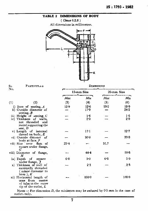
6.2.8 Dimensions of body and back nut shall conform to Tables 2 and 3 respectively.
6.3 Bonnet and Gland
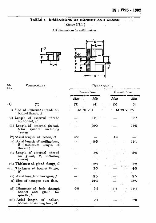
6.3.1 The dimensions of bonnet and gland shall be as given in Table 4. The internal thread in the bonnet shall be so formed that when the spindle is screwed into the bonnet to its fully open position, the end of the spindle projects beyond the face of the bonnet at least by 0.7 mm. A recess shall be formed at the top of the thread equal in depth to the depth of the thread and in length not greater than the dimension D specified in Table 4,
6.3.2 Hexagonal shoulder shall be provided on the bonnet.
6.3.3 To facilitate the removal of the bonnet, it shall be possible, when the tap is fully open to raise the easy-clean cover high enough to expose the full depth of the hexagon on the head.
6.3.4 The gland or stuffing box shall be packed with a suitable asbestos packing or other equally efficient packing material suitable for cold and hot water. A suitable washer may be fitted in the bottom of the gland or stuffing box, but this may be omitted if the packing is in the form of a moulded composition packing ring.
6
I%:1795 - 19iB2
TABLE 2 DIMENSIONS OF BODY ( ckausc 6.2‘8 )
All dimensions in millimetres.
SL No.
(1)
PARTICULAR
(2)
DIMENSION c_-_----*--------__~
E-mm Size 20-mm Size r----“_h-_-~ r-- h-_--Y
Max Min Max Min
(3) (4) (5) (6) i) Bore of seating, A 12.9 12.6 192 la.9
ii) Outside diameter of 17.9 242 seating, B
iii) Height of seating, C - ;:o”
- iv) Thickness of walls, - - ;:;
not threaded and metal supporting the seat, D
v) Length of internal - 11.1 - 12.7 thread on body, E
vi) Outside dimeter of .- 30.0 - 39.0 body at face, F
vii) Size over flats of 25.4 - 31.7 - square under flange, G
viii) Diameter of flange, - 44.4 50.8 H
ix) Depth of square 6.0 5.0 6.0 5.0 under flange, 3
x) Thickness of wall of - 2.3 2.3 externally threaded ( minor diameter to bore ), K
xi) Horizontal length of - 100’0 - 100.0 nose from centre of inlet to the outer tip of the outlet, L
NOTE - For dimension D, the minimum may be reduced by 0.5 mm in the case of outlets onlv.
7
IS : 1795 6 1982
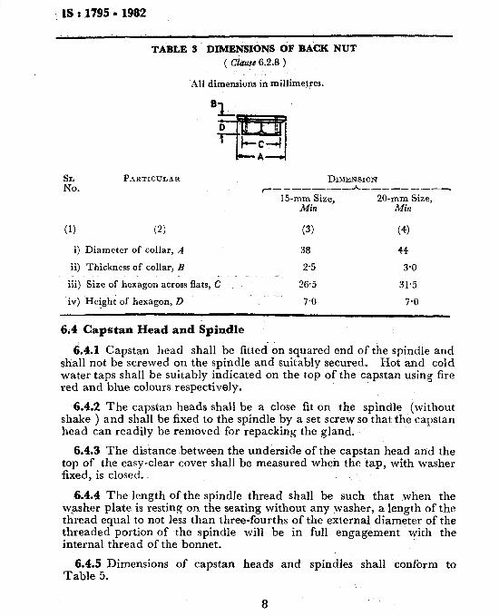
TABLE 3 DIMENSIONS OF BACK NUT
( Clause 6.2.8 )
AH dimensions in millimetres.
EA. PARTICULAR
(1) (2)
i) Diameter of collar, A
ii) Thickness of collar, B
iii) Size of hexagon across flats, C
iv) Heigh; of hexagon, D
DIMENSION c- -------- h--_-___---,
15-mm Size, 20-mm Size, Min Min
(3) (4)
38 44
2.5 3.0
26.5 31.5
7.0 7-O
6.4 Capstan Head and Spindle
6.4.1 Capstan head shall be fitted-on squared end of the spindle and shall not be screwed on the spindle and suitably secured. Hot and cold water taps shall be suitably indicated on the top of the capstan using fire red and blue colours respectively.
6.4.2 The capstan heads shall be a close fit on the spindle (without shake ) and shall be fixed to the spindle by a set screw so that the capstan head can readily be removed for repacking the gland.
6.4.3 The distance between the underside of the capstan head and the top of the easy-clear cover shall be measured when the tap, with washer fixed, is closed..
6.4.4 The length of the spindle thread shall be such that when the washer plate is resting on the seating without any washer, a length of~the thread equal to not less than three-fourths of the external diameter of the threaded portion of the spindle will be in full engagement with the internal thread of the bonnet.
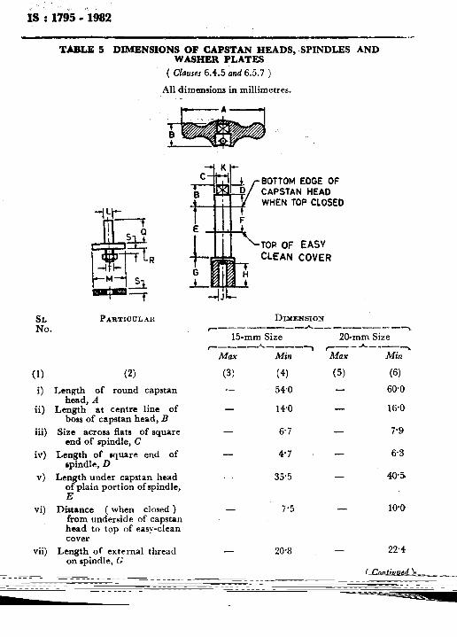
6.4.5 Dimensions of capstan heads and spindles shall conform to Table 5.
c.
l8 : 1795 - 1982
SL PARTICULAR DIXENSION No. ~_-----_--_h ---------~
15&m Size ~_--*-_-)
Max Min
20-mm Size ’ ~__A_--_~
Max Min
(1)
i)
ii)
(2) (3) _ (4)
Size of external threads on bonnet flange, A
Length of external thread on bonnet, B
M3Oxl
- 11.1
(5) (6)
M 39 x I.5
- 12.7
TABLE 4 DIMENSIONS OF BONNET AND GLAND
( Ckzusc 6.3.1 )
All dimensions in millimetres.
iii) Length of internal thread, C for spindle ‘ recess ’
including
iv) Axial length of recess, D
-
42
260
-
9.5 v) Axial length of stuffing box, - E ( minimum length of thread )
vi) Length of external thread - on gland, F, including runout
vii) Thickness of gland flange, G -
viii) Thickness of bonnet flange, - H
ix) Axial length of hexagon, 3 -
x) Size of hexagon over flats, - x
xi) Diameter of hole through bonnet and gland for spindle, L
9.9
xii) Axial length of collar, - bottom of stuffing box, M
7.6
2.8
3.5
9.5
21.5
9.6
2,4
- 21.5
46 -
-
11.1
a.8
. 3.2 - 45
- 9.5 - 23.5
11.5 11.2
- 2.8
9
is ': 1795 A982
. . TABLE 5 DIMENSIONS OF CAPSTAN HEADS, SPINDLES AND
WASHER PLATES
( Clauses 6.4.5 and 6.5.7 )
All d imensions in millimetres.
+---A-
-l Kl-
SL PA~TIOULAR No.
(1) (2) i) Length of round capstan
head, A ii) Length at centn line of
boss of capstan head, B
BOTTOM EOGE OF CAPSTAN HEAD WHEN TOP CLOSED
,TOP OF EASY CLEAN COVER
DIYEHSION r-------- h_---,----~,
15-mm 20-mm ~~~~-~~~-_~ *__--_
Size flats square of C
Length square of D
Length capstan of portion spindle,
Drtance when ) underside capstan to of
cover
6.7
4.7
35.5
(‘3 60.0
16.0
7.9
6.3
40.5
1OO
vii) Length of external thread on spindle, G
- 20.8 - 22.4
( Continued >
Max
(3)
Min
(4)
540
140
Max
(5)
-
10
SL No.
(1) viii)
ix)
x)
xi)
xii)
xiii)
xiv)
xv)
xvi)
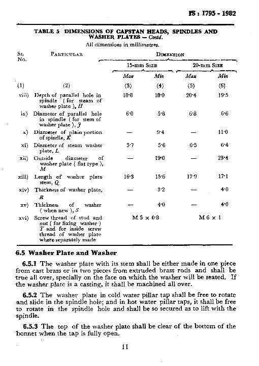
TABLE 5 DIMENSIONS OF CAPSTAN HEADS, SPINDLES AND WASHER PLATES - C’ontd.
All dimensions in millimetres.
PARTICULAR
(2)
DIXENSION ~--,-_,-----A- --------‘r
15-mm SIZB 20-mm Sxzn C_-h---_~C --A'I--y
Max Min MO% MiR
(3) (4) (5) (6)
Depth of parallel hole in spindle ( for steam of washer plate ), H
Diameter of parallel hole in spindle ( for stem of washer plate ), J
Diameter of plain portion of spindle, R
Diameter of steam washer plate, L
Outside diameter of rher plate ( flat type ),
Length of washer plate stem, Q
Thickness of washer plate,
R Thickness of washer
( when new ), S
Screw thread of stud and nut ( for fixing washer ) 7 and for inside screw thread of washer plate where separately made
18.8 18.0 20.4 19’5
6.0 5.8 6.8 6.6
- 9.4 - 11.0
5.7 5.6 6.5 6.4
- 190 - 23.4
16.3 15.6 17.9 17.1
- 3.2 - 4.0
40 - 40
M 5 x 0.8 M6xl
6.5 Washer Plate and Washer
6.5.1 The washer plate with its stem shall be either made in one piece from cast brass or in two pieces from extruded brass rods and shall be true all over, specially on the face on which the washer will be seated. If the washer plate is a casting, it shallbe machined all over.
6.5.2 The washer plate in cold water pillar tap shall be free to rotate and slide in the spindle hole; and in hot water pillar taps, it shall be free to rotate in the spindle hole and shall be so secured as to lift with the .spindle.
6.5.3 The top of the washer plate shall be clear of the bottom of the bonnet when the tap is fully open.
II
I§ : 1795 - 1982
6.5.4 Washer plates shall have a stud for attaching the washer. The stud shall be threaded and provided with a nut.
6.5.5 Replaceable washers conforming to the requirements of IS : 4346- 1982* shall always be provided for cold and hot water taps and shall be made of the materials specified in IS : 4346-1982*.
6.5.6 When the washer is fitted with a retaining ring, the internal diameter of the ring shall be greater than the external diameter of the seating to which it is fitted and the thickness of the washer shall not be less than 5 mm.
6.5.7 Dimensions of washer plate and washer shall conform to Table 5,
6.6 Screw Threads
6.6.1 General - All the screw threads other than inlet connection shall conform to the IS0 metric screw threads given in IS : 4218t. The inlet connection shall have parallel ( external ) pipe threads and back nut shall tr26y3rallel ( internal ) threads. The pipe threads shall conform to
: Z*
6.6.2 The screw threads on body, bonnet, gland, spindle and stuffing box shall conform to Table 6.
6.7 Anti-splash Device - Pillar tap shall, when required by the purchaser, be fitted with an anti-splash device. A typical example of” such a device is a corrugated sleeve formed from phosphor bronze strip 10 mm wide and O-45 mm thick of a composition complying grade I, II or III of IS : 7814-19758 and corrugated to a depth of 3 mm, cut to the appropriate length and bent to form a ring inside the outlet nose.
6.8 The inlet and outlet of pillar taps shall have sqdared up faces at the end to facilitate testing under pressure.
*Specification for washers for water taps for cold water services (Jirst revision ). $ISO metric screw threads:
Part I Part II
Basic and design profiles ( jrst reutrion ).
Part 1II Pitch diameter combinations (Jirst revision ).
Part IV Basic dimensions I‘or design profiles ( Jirst recision ).
Part V Tolerancing system (“first revision ). Tolerance
Part VI Limits of sizes for commercial bolts and nuts ( diameter range. 1 to 39 mm ) (Jirst revision ).
$Dimensions for pipe threads for fastening purposes: Part I Part II
Basic profile and dimensions
Part III Tolerances ( jirst revision ) . Limits of sizes (first revision ).
@pecification for phosphor bronze sheet, strip and foil.
12
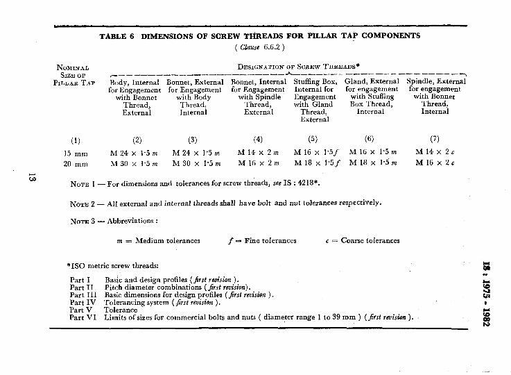
TABLE 6 DIMENSIONS OF SCREW TI-iREADS FOR PILLAR TAi’ COMPONENTS
( Clause 6.6.2 )
NOMINAL SIZE OF
PILLAR TAP
DESIGNATION OF SCREW THREUJS* ~_____--_-__-_-----__-_--- h__-__--_---------- ____ _y Body, Internal Bonnet, External Bonnet, Internal Stuffing Box, Gland, External Spindle, External for Engagement for Engagement for Engagement Internal for for engagement for engagement
with Bonnet with Body with Spindle Engagement with Stuffing with Bonnet Thread, Thread, Thread, with Gland Box Thread, Thread, External Internal External Thread, Internal Internal
External
(1) (2) (3) (4) (5) (6) (7)
15 mm M 24 x 1.5 m M 24 x 1.5 m Ml4x2m M 16 x 1’5f M 16 x 1.5 m Ml4x 2~
20 mm M 30 x 1.5 m M 30 x 1.5 m Ml6x2m M 18 x 1*5f M 18 x 1.5 th Ml6x2c
NOTE 1 - For dimensions and tolerances for screw threads, see IS : 4218*.
NOTE 2 - All external and internal threads shall have bolt and nut tolerances respectively.
NOTE 3 - Abbreviations :
m = Medium tolerances f = Fine tolerances G = Coarse toIerances
*ISO metric screw threads:
Part I Basic and design profiles (first revision ). Part II Pitch diameter combinations (first reuirion). Part III Basic dimensions for design profiles (Jirst revision ) . Part IV Tolerancing system ( jirst revision ). Part V Tolerance Part VI Limits of sizes for commercial bolts and nuts ( diameter range 1 to 39 mm ) (first icvision ). i
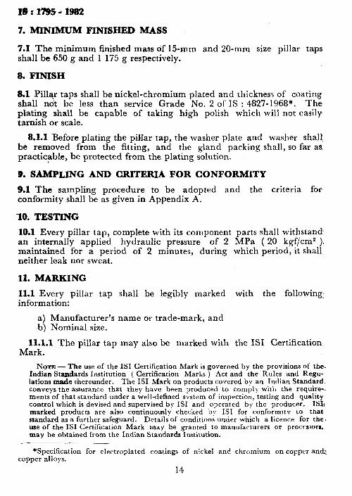
7. MINIMUM FINISHED MASS
7.1 The minimum finished mass of 15-mm and 20-mm size pillar taps shall be 650 g and 1 175 g respectively.
8. FINISH
8.1 Pillar taps shall be nickel-chromium plated and thickness of coating shall ndt be less than service Grade No. 2 of IS : 4827-1968*. The plating shall be capable of taking high polish which will not easily tarnish or scale.
8.1.1 Before plating the pillar tap, the washer plate and washer shalt be removed from the fitting, and the gland packing shall, so far as practicable, be protected from the plating solution.
9, SAMPLING AND CRITERIA FOR CONFORMITY
9.1 The sampling procedure to be adopted and the criteria for- conformity-shall be as given in Appendix A.
10. TESTING
10.1 Every pillar tap, complete with its component parts shall withstand! an internally applied hydraulic pressure of 2 MPa ( 20 kgf/cma ), maintained for a period of 2 minutes, during which period, it shall neither leak nor sweat.
11. MARKING
11.1 Every pillar tap shall be legibly marked with the following: information:
a) Manufacturer’s name or trade-mark, and b) Nominal size.
11.l.l The pillar tap may also be marked with the ISI Certification Mark.
NOTE - The use of the IS1 Certification Mark is governed by the provisions of‘ the. Indian Standards institution ( Certification Marks ) Act and the Rules and Regu- lations made thereunder. The IS1 Mark on products covered by an Indian Standard. conveys the assurance that they have been produced to comply with the require-. ments of that standard under a well-defined system of inspection, testing and quality control which is devised and supervised by IS1 and operated by the producer. ISI1 marked products are also continuously checked b\s IS1 for conformity to that standard as a further safeguard. Details of conditions under which a licence for the. use of the IS1 Certification Mark may be granted to manufacturers or proceslorr, may be obtained from the Indian Standards Institution.
*Specification for electroplated coatings of nickel and chromium on copper and: copper alloys.
14
Is : 1795 - 1982
APPENDIX A
( C’hJzJse 9.1 3
SAMPLING +ND CR1TERI.J FOR CONPORMITY
A-I. SAMPLING
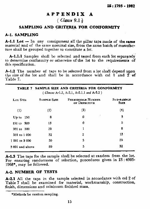
A-l.1 Lot - In any consignment all the pillar taps made of the r@rr~e material and of the same nominal size, from the same batch of manufac- ture shall be grouped together to constitute a lot.
A-1.1.1 Samples shall be selected and tested from each lot msepargtely to determine conformity or otherwise of the lot to the requirements of this specification.
A-l.2 The number of taps to be selected from a lot shall depend up,on the size of the lot and shall be in accordance with co1 1 and 2 of Table 7.
TABLE 7 SAMPLE SIZE AND CRITERIA FOR CONFORMITY ( Clauses A-1.2, A-2.1, A-2.1.1 and A-3.2 )
LOT SIZE SANPLBI SIZE PERYISSIBLE NUMBER SUB-IALIPLE OB DEFECTIVE Srzm
(1) (2) (3) (4)
up to 150 8 !I 3
151 to 300 13 0 5
301-to 500 20 1 8
501 to 1 000 32 2 13
1 001 to 3 000 50 3 20
3 001 and above 80 5 32
A-l.3 The taps for the sample shall be selected at random from the lot. For ensuring randomness of selection, procedures given in IS : 4905- 1968*, may be followed.
A-2. NUMBER OF TESTS
A-2.1 All the taps in the sample selected in accordance with co1 2 of
Table 7 shall be examined for material, workmanship, construction, snish, dimensions and minimum finished mass.
*Methods for random sampling.
15
IS : 1795 - 1982
A-2.1.1 The number of taps to be tested for hydraulic pressure test shall be in accordance with co1 4 of Table 7. This sub-sample shall be selected from those taps which have been already examined under A-2.1 and have been found conforming to the requirements of this standard listed in A-2.1.
A-3. CRITERIA FOR CONFORMITY
A-3.1 The lot shall be considered conforming to the requirements of this specification if the conditions in A-3.2 and A-3.3 are satisfied.
A-3.2 The number of taps failing to satisfy the requirements for one or more of the characteristics mentioned in A-2.1 shall not exceed the, correspondingnumber given in co1 3 of Table 7.
A-3.3 No tap in the sub-sample shall fail in hydraulic test ( see 10.1 ).
16