Embed Size (px)
Citation preview

Disclosure to Promote the Right To Information
Whereas the Parliament of India has set out to provide a practical regime of right to information for citizens to secure access to information under the control of public authorities, in order to promote transparency and accountability in the working of every public authority, and whereas the attached publication of the Bureau of Indian Standards is of particular interest to the public, particularly disadvantaged communities and those engaged in the pursuit of education and knowledge, the attached public safety standard is made available to promote the timely dissemination of this information in an accurate manner to the public.
इंटरनेट मानक
“!ान $ एक न' भारत का +नम-ण”Satyanarayan Gangaram Pitroda
“Invent a New India Using Knowledge”
“प0रा1 को छोड न' 5 तरफ”Jawaharlal Nehru
“Step Out From the Old to the New”
“जान1 का अ+धकार, जी1 का अ+धकार”Mazdoor Kisan Shakti Sangathan
“The Right to Information, The Right to Live”
“!ान एक ऐसा खजाना > जो कभी च0राया नहB जा सकता है”Bhartṛhari—Nītiśatakam
“Knowledge is such a treasure which cannot be stolen”
“Invent a New India Using Knowledge”
है”ह”ह
IS 1448-71 (2004): Methods of Test for Petroleum and itsProducts, Part 71: Liquefied Petroleum Gases -Determination of Gauge Vapour Pressure - LPG Method [PCD 1:Methods of Measurement and Test for Petroleum, PetroleumProducts and Lubricants]


IS1448[P:71] :2004ISO 4256:1996
Indian Standard
METHODS OF TEST FOR PETROLEUM AND ITSPRODUCTS
[P: 71]
LIQUEFIED PETROLEUM GASES — DETERMINATIONPRESSURE — LPG METHOD
( Second Revision)
OF GAUGE VAPOUR
~CS 75.160.30
Q BIS 2004
BUREAU OF INDIAN STANDARDSMANAK BHAVAN, 9 BAHADUR SHAH ZAFAR MARG
NEW DELHI 110002
August 2004 Price Group 4

Methods of Measurement and Test for Petroleum, Petroleum Products and Lubricants SectionalCommittee, PCD 1
NATIONAL FOREWORD
This Indian Standard [ P :71 ] ( Second Revision ) which is identical with ISO 4256:1996 ‘Liquefiedpetroleum gases — Determination of gauge vapour pressure — LPG method’ issued by the InternationalOrganization for Standardization ( ISO ) was adopted by the Bureau of Indian Standards on the recommend-ations of the Methods of Measurement and Test for Petroleum, Petroleum Products and LubricantsSectional Committee and approval of the Petroleum, Coal and Related Products Division Council,
First revision of this standard was published in 1979, which was based on ASTM D 1267 and ISO 4256.Since ISO 4256 has subsequently been revised as ISO 4256:1996, the Committee, therefore decidedto revise this Indian standard to completely align with ISO 4256: 1996 and publish under the dualnumbering system. Consequently the title of the standard has been modified.
The text of ISO Standard has been proposed to be approved as suitable for publication as an IndianStandard without deviations. Certain conventions are, however, not identical to those used in IndianStandards. Attention is particularly drawn to the following:
a) Wherever the words ‘International Standard’ appear referring to this standard, they should beread as ‘Indian Standard’.
b) Comma ( , ) has been used as a decimal marker while in Indian Standards, the current practiceis to use a point ( . ) as the decimal marker.
CROSS REFERENCES
In this adopted standard reference appears to certain International Standards for which Indian Standardsalso exist. The corresponding Indian Standards, which are to be substituted in their place, are listedbelow along with their degree of equivalence for the editions indicated. However, that InternationalStandard cross-referred in this adopted ISO Standard, which has subsequently been revised, positionin respect of that latest [S0 Standard has been given:
International Standard
1s0 3007 : 1986 Petroleumproducts — Determination of vapourpressure — Reid method properties
ISO 4257:1988 Liquefied petroleumgases — Method of sampling
Corresponding tndian Standard Degree of Equivalence
IS 1448 [ P :39 ] :1967 Methods Technically equivalentof test for petroleum and its with minor deviationsproducts [ P :39 ] Vapour pressureby Reid method ( first revision)
IS 1447 ( Part 2 ) :1992 Methodsof sampling of petroleum and its
do
produc”ts: ‘Part’ 2 Sampling ofliquefied petroleum gas ( LPG )( first revision)
For tropical countries like India, the Standard temperature and the relative humidity shall be takenas 27 & 2°C and 65 * 5 percent respectively.
In reporting the results of a test or analysis made in accordance with this standard, if the final value,observed or calculated, is to be rounded off, it shall be done in accordance with IS 2 :1960 ‘Rules forrounding off numerical values ( revised )’.

IS 1448 [ P :71 ] :2004
ISO 4256:1996
hdian Standard
METHODS OF TEST FOR PETROLEUM AND ITSPRODUCTS
[P: 71]
LIQUEFIED PETROLEUM GASES — DETERMINATION OF GAUGE VAPOURPRESSURE — LPG METHOD
( Second Revision)
W-ARNING — The use of this International Standard may involve hazardous materials, operations andequipment. This standard does not purport to address all of the safety problems associated with its use. Itis the responsibility of the user of this International Standard to establish appropriate safety and healthpractices and determine the applicability of regulatory limitations prior to use.
1 Scope
This International Standard describes a method for thedetermination of gauge vapour pressures of liquefiedpetroleum gas products (see clause 3) at temper-atures within the approximate range of 35 ‘C to 70 ‘C.
NOTES
1 Information on the vapour pressure of liquefied petro-leum gases is required for the selection of properly de-signed storage vessels, shipping containers and customerutilization equipment, to ensure the safe handling of theseproducts, and to ensure that maximum operating designpressures are not exceeded under the foreseen ambientoperating conditions,
of IEC and ISO maintain registers of currently valid in-ternational Standards.
ISO 3007:1986, Petroleum products — Determinationof vapour pressure — Reid method.
ISO 4257:1988, Liquefied petroleum gases — Methodof sampling.
3 Definitions
For the purposes of this International Standard, thefollowing definitions apply.
2 The vapour pressure of liquefied petroleum gases is anindirect measure of the lowest temperature at which initial 3.1 vapour pressure: Pressure exerted by the va-
va~orization can be ex~ected to occur, It may also be con- pour of a liquid when in equilibrium with the liquid.
sidered to be an indirect indication of the most volatile con-stituent present in the product. In this International Standard, the term “vapour press-
ure” shall be understood as gauge vapour pressure,which is absolute vapour pressure minus atmospheric
2 Normative references
The following standards contain provisions which,through reference in this text, constitute provisions ofthis International Standard. At the time of publication,the editions indicated were valid. All standards aresubject to revision, and parties to agreements basedon this International Standard are encouraged to in-vestigate the possibility of applying the most recenteditions of the standards indicated below. Members
pressure.
3.2 liquefied petroleum gas (LPG): Hydrocarbongas that can be stored and/or handled in the liquidphase under moderate conditions of pressure and atambient temperature. It consists essentially of C3 andC4 alkanes or alkenes, or a mixture of these, containsgenerally less than 5 YO by liquid volume of material ofhigher carbon number, and has a gauge vapour pres-sure not exceeding approximately 1 600 kPa at 40 ‘C.
1
IS 1448 [ P: 71 ] :2004
ISO 4256:1996
4 Principle
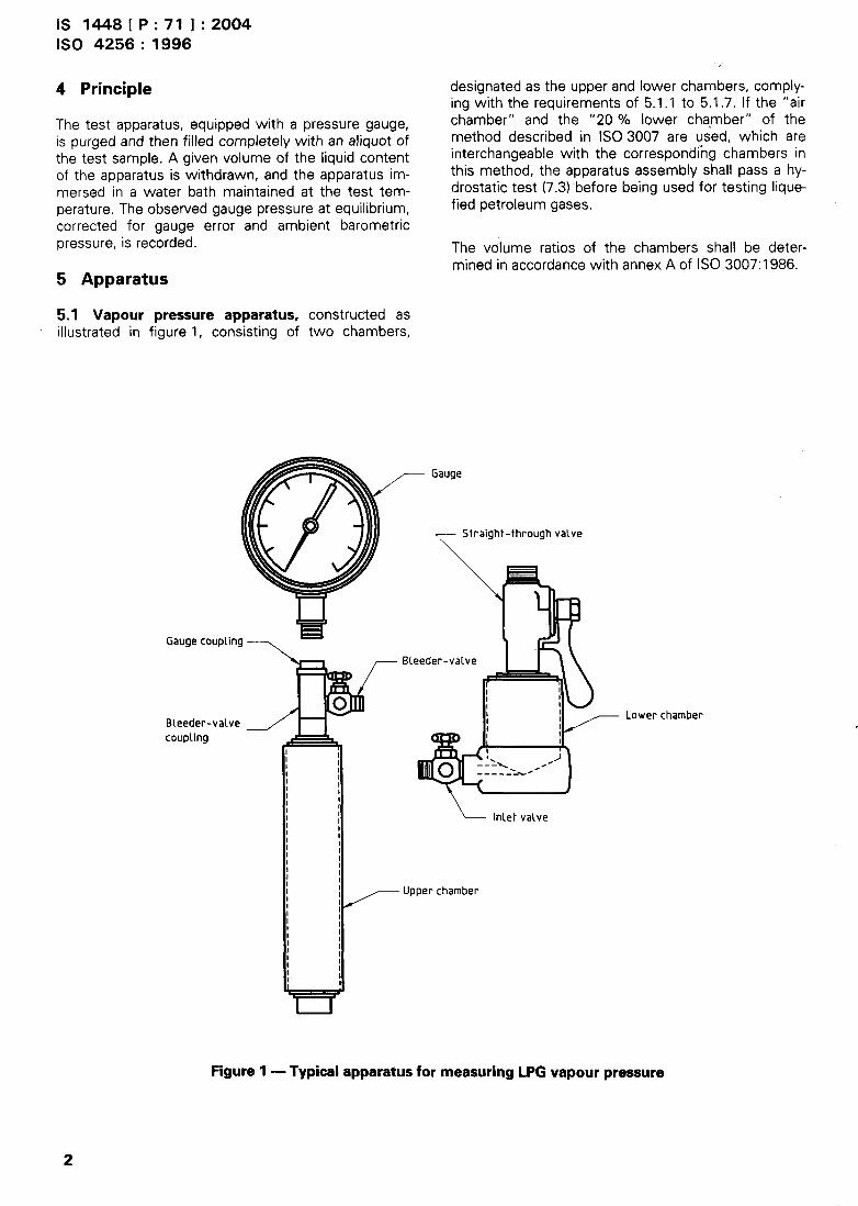
The test apparatus, equipped with a pressure gauge,is purged and then filled completely with an aliquot ofthe test sample. A given volume of the liquid contentof the apparatus is withdrawn, and the apparatus im-mersed in a water bath maintained at the test tem-perature. The observed gauge pressure at equilibrium,corrected for gauge error and ambient barometricpressure, is recorded.
5 Apparatus
5.1 Vapour pressure apparatus, constructed asillustrated in figure 1, consisting of two chambers,
@
o
w—Gaugecoupling7—
Bleeder-valvecoup~ing
designated as the upper and lower chambers, comply-ing with the requirements of 5.1.1 to 5.1.7. If the “airchamber” and the “20 YO lower chamber” of themethod described in ISO 3007 are used, which areinterchangeable with the corresponding chambers inthis method, the apparatus assembly shall pass a hy-drostatic test (7.3) before being used for testing lique-fied petroleum gases.
The volume ratios of the chambers shall be deter-mined in accordance with annex A of ISO 3007:1986.
& /“--- ‘auge
~ Straight-through valve
%
- 3?/_‘Leeder-va’veJ ‘ ‘‘I
I
I
‘L--- Inletvalve
Upper chamber
— Lower cl
Figure 1 — Typical apparatus for measuring LPG vapour
2
pressure

5.1.1 Upper chamber, consisting of a cylindricalvessel of inside dimensions 51 mm * 3 mm in diam-eter and 254 mm * 3 mm in length, with the inner sur-faces of the ends slightly sloped to provide completedrainage from either end when held in a vertical pos-ition. At one end of the upper chamber, a suitablebleeder-valve coupling shall be provided to receive thebleeder-valve assembly and the pressure gauge. Atthe other end of the chamber, an opening approxi-mately 13 mm in diameter shall be provided forcoupling with the lower chamber. Care shall be takenthat the connections to the end openings do not pre-vent the chamber from draining completely.
5.1.2 ‘Lower chamber, 33 1/3 9’o, a cylindrical vesselof volume such that the ratio of the volume of the up-per chamber to the volume of the lower chamber is2 f 0,03 (see note 1, 5.1 .3).
5.1.3 Lower chamber, 20 Y., a cylindrical vessel ofvolume such that the ratio of the volume of the upperchamber to the volume of the lower chamber is4 ~ 0,05 (see notes 1 and 2).
NOTES
1 In determining the volumetric capacities of the cham-bers, the volume of the lower chamber is considered asthat which is below the “straight-through” valve closure.The volume above the “straight-through” valve closure, in-cluding the portion of the coupling attached to the upperchamber, is considered as part of the upper chamber vol-ume.
2 The apparatus requirements for this method, excludingthe bleeder-valve assembly, are identical with those ofISO 3007 with the exception of the 33 ID % lower cham-ber. Although the test procedure details are different, theair and liquid chambers of ISO 3007 may be used in thepresent method provided that they are of sufficientstrength to withstand the higher test pressures (7.3).
5.1.4 Bleeder-valve assembly.
The bleeder-valve for purging the apparatus shall be anominal 6 mm valve fitted into the side of the bleeder-valve coupling. The lower end shall be threaded to fitinto the end fitting of the upper chamber, and theupper end shall be threadedcoupling.
5.1.5 Valves and coupling.
to receive the gauge
At one end of the lower chamber, an opening ap-proximately “19 mm in diameter shall be provided toreceive a suitable straight-through valve having aminimum internal channel of 13 mm diameter. Theother end of the chamber shall be equipped with anominal 6 mm inlet valve.
IS 1448 [ P :71 ] :2004
ISO 4256:1996,
NOTE — Any method of coupling the chambers may beemployed provided that the volumetric requirements aremet and that the assembly is free from leaks under theconditions of the test.
5.2 Pressure gauge
A Bourdon-type spring gauge of test gauge quality114 mm to 140 mm in diameter, provided with anominal 6 mm male thread connection with a pass-ageway not less than 5 mm in diameter from theBourdon tube to the atmosphere.
The range and graduations of the pressure gaugeused shall be governed by the vapour pressure of thesample being tested, as shown in table 1.
The observed gauge readings shall be corrected for“gauge error” in accordance with 9.2, either by directcalibration against a dead-weight tester (5.5), or by theuse of a second gauge certified by a recognized offi-cial body.
Table 1 — Specifications for pressure gauges
LPGGauge specifications
vapour Scale Maximum Maximumpressure range numbered intermediate
intewals graduations
kPa kPa
<655 0 to 700 70 3,5
620 to 1730 0 to 2000 175 7
I 660 to 3460 0 to 3500 350 35
5.3 Vapour pressure bath, of dimensions such thatthe bleeder-valve assembly is completely immersedwhen the vapour pressure apparatus is inserted in anupright position.
The bath shall be capable of maintaining the test tem-perature within the following limits:
a) for test temperature S 50 “C: + 0,1 “C;
b) for test temperature >50 “C: * 0,3 ‘C.
5.4 Temperature sensor, either a thermometerconforming to the specifications given in annex A, or asuitably calibrated electronic measuring device ofequivalent accuracy.
The thermometer shall be positioned in the bath insuch a manner that it can be viewed throughout thetest and adjusted so that it is immersed to the testtemperature graduation mark.
3

IS 1448 [ P :71 ] :2004
ISO 4256:1996
5.4.1 Low-range thermometer, for indicating test 7.3 Hydrostatic testtemperatures between 35 “C.and 40 ‘C.
The assembled chambers shall be certified by the
5.4.2 Middle-range thermometer, for indicating testmanufacturer to withstand approximately 7000 kPa
temperature.. s~t.ween 41 ‘C and 50 “C.gauge hydrostatic pressure without permanent de-formation.
5.4.3 High-range thermometer, for indicating test 7.4 Leak testtemperatures between 51 “C and 80 “C.
Before placing new apparatus in service, and each
5.5 Dead-weight tester, of satisfactory range, as atime the apparatus is used after a period of at least aweek of nonutilization, the assembled vapour press-
means of checking the accuracy of vapour pressuregauges.
ure apparatus shall be checked for freedom fromleaks by filling it with air, natural gas, nitrogen, or
NOTE — If the second gauge (5.2) is certified by a recog-other similar gases, to 3500 kPa gauge pressure, and
nized official body, this apparatus is unnecessary.then completely immersing it in a water bath. Onlyapparatus that will withstand this test without leakingshall be used.
6 Sampling and sample handling
8 Procedure6.1 Obtain and store samples in accordance withISO 4257 unless the test samples are taken directlyfrom the source of the material to be tested.
8.1 General
For specific hazard statements, see annex B.6.2 Use any convenient method of coupling the va-pour pressure apparatus to the sample source. If necessary, chill the apparatus with a portion of the
material under test to facilitate transfer, either for
A minimum length of tubing, 6 mm to 7 mm in diam-eter, of grade appropriate to the pressure range in-volved in the test, and made of material corrosion-resistant to the products being sampled, is satisfac-tory for this purpose. If a flexible tubing connection isused, the tubing shall be made of an electrically con-ductive material or constructed with a built-in earth(ground) connection to minimize the effect of staticelectricity.
6.3 Additional safety precautions for the handling ofliquefied petroleum gases, given in annex B, shall bemeticulously observed during all the following oper-ations.
7 Preparation of apparatus
7.1 Cleaning
Disassemble the apparatus, clean thoroughly, andpurge the parts in a stream of dry air.
7.2 Assembling
Assemble the apparatus with the inlet valve of thelower chamber open, the straight-through valve be-tween the two chambers open, the bleeder-valveclosed, and the pressure gauge (5.2) attached.
purging (8.2) or for introduction of test sample (8.3).Close the inlet valve and open the bleeder-valve to itswide-open position. Allow the contained sample toevaporate until the apparatus is cooled to well belowthe temperature of the sample source. Expel any re-sidual material remaining after this operation from theapparatus through the bleeder-valve by inverting theassembly. Close the bleeder-valve. Return the chilledapparatus to its normal upright position, and take thetest sample in the manneroutlined below.
8.2 Purging
With the assembled apparatus (7.2) in an upright pos-ition, connect the inlet valve of the lower chamber tothe sample source using the sampling connection(6.2). Open the sample source valve to the apparatus.Cautiously open the bleeder-valve on the upper cham-ber, permitting the apparatus to fill with liquid (see8.1 ). With the sampling line still connected, close thebleeder-valve and the inlet valve in that order. Quicklyinvert the apparatus, open the bleeder-valve, and holdthe apparatus in this position until all the liquid hasbeen expelled. Allow the residual vapours to escapeuntil the pressure in the apparatus is essentially at-mospheric, then close the bleeder-valve.
WARNING— All practical work should be carriedout without stoppage time to avoid excessivepressure buildup.
4

IS1448[P:71] :2004
ISO 4256:1996
8.3 Introduction of test sample
Return the apparatus, now containing only vapours, toits normal upright position and open the inlet valve. Assoon as the apparatus attains essentially the samep~essure as at the sample source, momentarily openthe bleeder-valve. If liquid does not promptly emerge,repeat the purging step (8.2). If liquid appears im-mediately, close the bleeder-valve and inlet valves inthat order (see 8.1 ). Close the valve on the samplesource, and disconnect the sampling line. Immediatelyclose the straight-through valve between the twochambers and open the inlet valve, with the apparatusin an upright position. Close the inlet valve as soon asno more liquid escapes, and immediately open thestraight-through valve.
.When using the 33 1/3 YO lower chamber (5.1 .2), pro-ceed to 8.4,
When using the 20 Y. lower chamber (5.1 .3), closethe straight-through valve and for a second time openthe inlet to permit expulsion of the lower chambercontents. As soon as no more liquid escapes from thelower chamber, close the inlet valve and immediatelyopen the straight-through valve.
gauge vapour pressure” of the sample at the testtemperature.
NOTE — Under normal operating conditions, constant con-secutive gauge readings are achieved after a period of20 min to 30 min.
8.4.3 Record the observed barometric pressure (~b)required for the calculation in clause 9.2.
9 Determination of gauge error
9.1 If a noncalibrated gauge has been used to obtainthe observed uncorrected gauge w+pour pressure, the“gauge error” shall be determinated at the end of thetest by the procedure described in 9.2. The readingsobtained shall not be regarded as test results, as theconditions of measurement differ.
9.2 Wtthout removing the pressure gauge from theapparatus or the apparatus from the bath, attach atest gauge (5.2) to the bleeder-valve outlet and openthe bleeder-valve. At the end of 5 min compare thereadings of the two gauges. Record any correctionthus determined as “gauge error”.
8.4 Vapour pressure determination10 Calculation
.8.4.1 Invert the apparatus and shake it vigorously.Return the apparatus to its normal upright position.Immerse the apparatus including the bleeder-valvecoupling, but excluding the pressure gauge, in theconstant-temperature bath maintained at the testtemperature.
Throughout the determination, take the temperatu~eof the water bath periodically by means of the baththermometer. At test temperatures s 50 “C, maintainthe bath within f 0,1 ‘C of the test temperature; attest temperatures >50 “C, maintain the bath withint 0,3 “C of the test temperature. Observe the appar-atus assembly throughout the test period to ensurefreedom from leaks. Discontinue the test and discardthe results if at any time a leak is detected.
8.4.2 After 5 min have elapsed, withdraw the ap-paratus from the water bath, invert it, shake it vigor-ously along the vertical axis, and then return it to thebath; perform the shaking operation quickly to avoidexcessive cooling of the apparatus and its contentsThereafter, at intervals of not less than 2 rein, with-draw the apparatus from the bath, invert it, shake itvigorously and then return it to the bath. Prior to eachremoval of the apparatus from the water bath, tap thegauge lightly and observe the pressure reading. Con-tinue these operations until two consecutive gaugereadings do not differ by more than 5 kPa. After thistime, record the pressure reading as the “uncorrected
10.1 Correct the “uncorrected vapour pressure” forgauge errors (see 9.2).
10.2 Convert the corrected vapour pressure (10.1) toa standard barometric pressure of 101,3 kPa bymeans of the following equation.
~“=~~–(lol,a–~b)
where
pv is the gauge vapour pressure converted to astandard absolute barometric pressure of101,3 kPa, in kilopascals;
p. k the corrected gauge vapour pressure (10.1), inkilopascals;
pb is the observed absolute barometric pressure(8.4.3), in kilopascals.
11 Expression of results
Report the gauge vapour pressure result to the near-est 5 kPa, together with the test temperature.
5

IS1448[P: 711
ISO 4256:1996
12 Precision
:2004
12.1 Repeatabil”~, r
The difference between two test results obtained by
the same operator with the same apparatus underconstant operating conditions on identical test mate-rial would, in the normal and correct operation of thetest method, exceed the value below only in one casein 20:
~=12kpa
12.2 Reproducibility, R
The difference between two single and independent
results obtained by different operators working in dif-ferent laboratories on nominally identical test materialwould, in the normal and correct operation of the testmethod, exceed the value below only in one case in20:
R= 19kPa
13 Test report
The test report shall contain at least the following in-formation:
a)
b)
c)
d)
e)
a reference to this International Standard;
all details necessary for complete identification ofthe product tested;
the result .of the test (see clause 10);
any deviation, by agreement or otherwise, fromthe standard procedures specified;
the date of the test.
6

IS1448[P:71] :2004
ISO 4256:1996
Annex A(normative)
Specifications for thermometers
A.1 The thermometers specified in 5.4 shall meet the requirements given in table A. 1.
Table A.1 — Specifications for thermometers
Characteristics Low-range Middle-range High-range
Range ...................................................................... “C 34 to 42 25 to 55 50 to 80
Immersion ............................................................... Total Total Total
Graduation at each .................................................. ‘C 0,1 0,1 0,1
Longer lines at each ................................................ ‘C 0,5 0,5 0,5
Figured at each ....................................................... ‘C 1 1 1
Scale error not to exceed ........................................ ‘C 0,1 0,1 0,1
Expansion chamber permitting heating to .............. “C 100 105 130
Overall length .......................................................... mm 275 t 5 379 * 5 379 & 5
Stem diameter ........................................................ mm 6t07 7t08 7t08
Bulb length .............................................................. mm 25 to 35 25 to 35 25 to 35
Bulb diameter .......................................................... mm >5 and < stem 6t07 6t07
Distance from bottom of bulb to line at .................. ‘C: mm 34,4: 13.5 to 150 25:115to 135 50:115to 135
Distance from bottom of bulb to line at .................. ‘C: mm 42:215 to 234 55:324 to 344 80:324 to 344
Distance from bottom of bulb to top of contractionchamber (max.) ....................................................... mm 60 100 100
Distance from bottom of bulb to bottom ofcontraction chamber (min.) ..................................... mm 80 80
Stem enlargement diameter ................................... mm 8to10
Stem enlargement length ....................................... mm
—
4t07 ~
Distance from bottom of bulb to bottom of stem
—
enlargement ............................................................ mm l12tol16 —
The following thermometers comply with the specifications given in table A.1:
Low-range: ASTM 18 C/lP23CMiddle-range: ASTM 64 CHigh-range: ASTM 65 C
7
IS 1448 [ P :71 ] :2004
ISO 4256:1996
Annex B
(nonnative)
Safety precautions
6.1 General precautions
B.1.l The safety precautions regarding the practiceof handling liquefied petroleum gases in the laboratoryshall be meticulously observed during the determi-nation specified in this International Standard.
B.1.2 Liquefied petroleum gases can cause seriouscold burns. Care shall be taken, therefore, to preventthe liquid from coming into contact with the skin;when handling liquefied petroleum gases, protectivegoggles and gloves shall be worn.
B.1.3 Discharge of Iiquelied petroleum gases can
give rise to static electricity, and it is essential to con-
nect apparatus to earth (ground) before discharging.
B.1.4 Take care to avoid breathing petroleum va-pours during the determination of vapour pressure.
B.1.5 Care shall be taken that it is safe to dischargeliquefied petroleum gases in the vicinity during unagi-ng operations.
B.2 Specific precautions for thisInternational Standard
B.2.1 Re: subclause 8.2
Safe means for the disposal of vapours and liquidsduring this operation and in the subsequent samplingoperation (8.3) shall be provided.
B.2.2 Re: subclause 8.3
a)
b)
Materials of high liquid coefficient of expansion,such as propene, if introduced in the apparatus attemperatures near their boiling point and thenwarmed to test temperatures, could expand suf-ficiently to cause the apparatus full of liquid torupture. Th-erefore, if the 20 YO lower chamber isused for such samples, it is imperative that the40 Y. ullage procedure be completed promptly.
The upper chamber, prior to this operation, is fullof liquid at some temperature that is normallybelow the environmental temperature. Since anywarming of the apparatus would cause expansionof the liquid content of the upper chamber, lead-ing to possible rupture of the chamber, it isnecessary that the procedural steps of providingfree space in the apparatus be completedpromptly.
8

Bureau of Indian Standards
BIS is a statutory institution established under the Bureau of/ndian Startcfards Act, 1986 to promoteharmonious development of the activities of standardization, marking and quality certification ofgoods and attending to connected matters in the country.
Copyright
BIS has the copyright of all its publications. No part of these publications maybe reproduced in anyform without the prior permission in writing of BIS. This does not preclude the free use, inthecourseof implementing the standard, of necessary details, such as symbols and sizes, type or gradedesignations. Enquiries relating to copyright be addressed to the Director (Publications), BIS.
Review of Indian Standards
Amendments are issued to standards as the need arises on the basis of comments. Standards arealso reviewed periodically; a standard along with amendments is reaffirmed when such reviewindicates that no changes are needed; if the review indicates that changes are needed, it is takenup for revision. Users of Indian Standards should ascertain that they are in possession of the latestamendments or edition by referring to the latest issue of ‘BIS Catalogue’ and ‘Standards : MonthlyAdditions’.
This Indian Standard has been developed from Doc : No. PCD 1 ( 1915 ).
-Amendments Issued Since Publication
Amend No. Date of Issue Text Affected
BUREAU OF INDIAN STANDARDS
Headquarters:
Manak Bhavan, 9 Bahadur Shah Zafar Marg, New Delhi 110002
Telephones :23230131, 23233375, 23239402 Website : www. bis.org. in
Regional Offices :
Central :
Eastern :
Northern :
Southern :
Western :
Branches:
Manak Bhavan, 9 Bahadur Shah Zafar MargNEW DELHI 11 OOO2
1/14 C. 1. T. Scheme Vll M, V. 1. P. Road, KankurgachiKOLKATA 700054
SCO 335-336, Sector 34-A, CHANDIGARH 160022
C. 1.T. Campus, IV Cross Road, CHENNAI 600113
Manakalaya, E9 MlDC, Marol, Andheri (East)MUMBAI 400093
Telephones
{2323761723233841
{
23378499,2337856123378626,23379120
{
26038432609285
{
2254 1216, 2254 14422254 2519, 2254 2315
{
28329295,2832785828327891,28327892
AHMEDABAD. BANGALORE. BHOPAL. BHUBANESHWAR. COIMBATORE.FARIDABAD. GHAZIABAD. GUWAHATI. HYDERABAD. JAIPUR. KANPUR.LUCKNOW. NAGPUR. NALAGARH. PATNA. PUNE. RAJKOT. THIRUVANANTHAPURAM.VISAKHAPATNAM.
,
Printed at New India Printing Press, Khuqa, India