Embed Size (px)
DESCRIPTION
IRTF Adaptive Optics System Review. Overview. IRTF is building a 36 element curvature based AO system Purpose of this Review - Is to identify any remaining design, installation or operational problems and to expose the IRTF staff to the system details - PowerPoint PPT Presentation
Citation preview
IRTF Adaptive Optics System Review
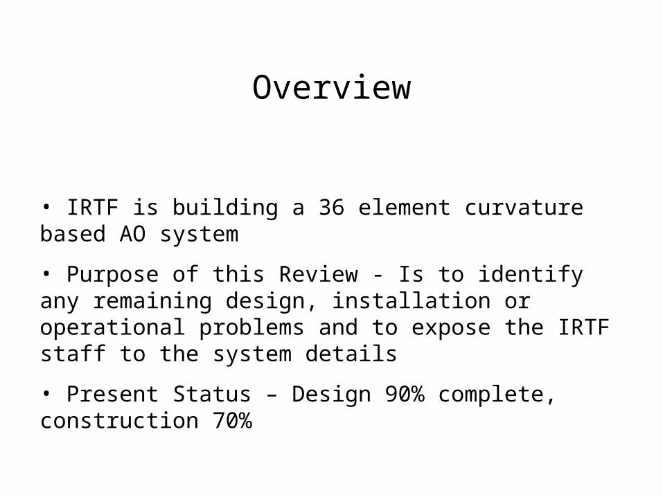
• IRTF is building a 36 element curvature based AO system
• Purpose of this Review - Is to identify any remaining design, installation or operational problems and to expose the IRTF staff to the system details
• Present Status – Design 90% complete, construction 70%
Overview
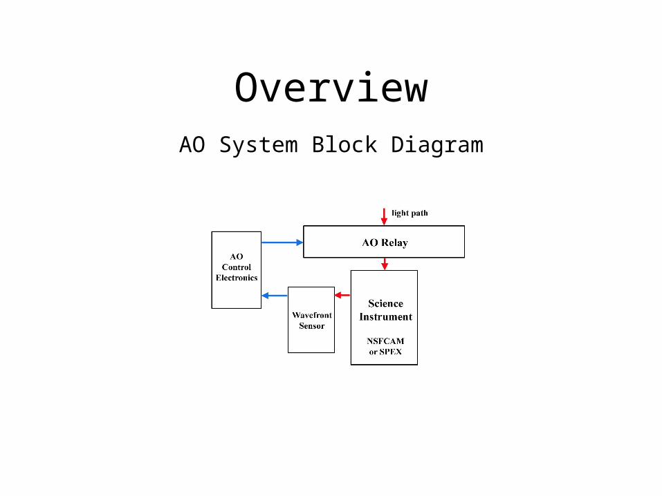
OverviewAO System Block Diagram

AO Relay
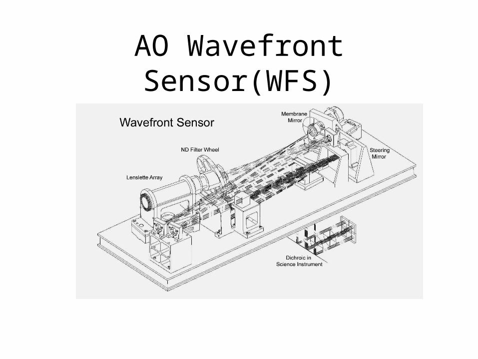
AO Wavefront Sensor(WFS)
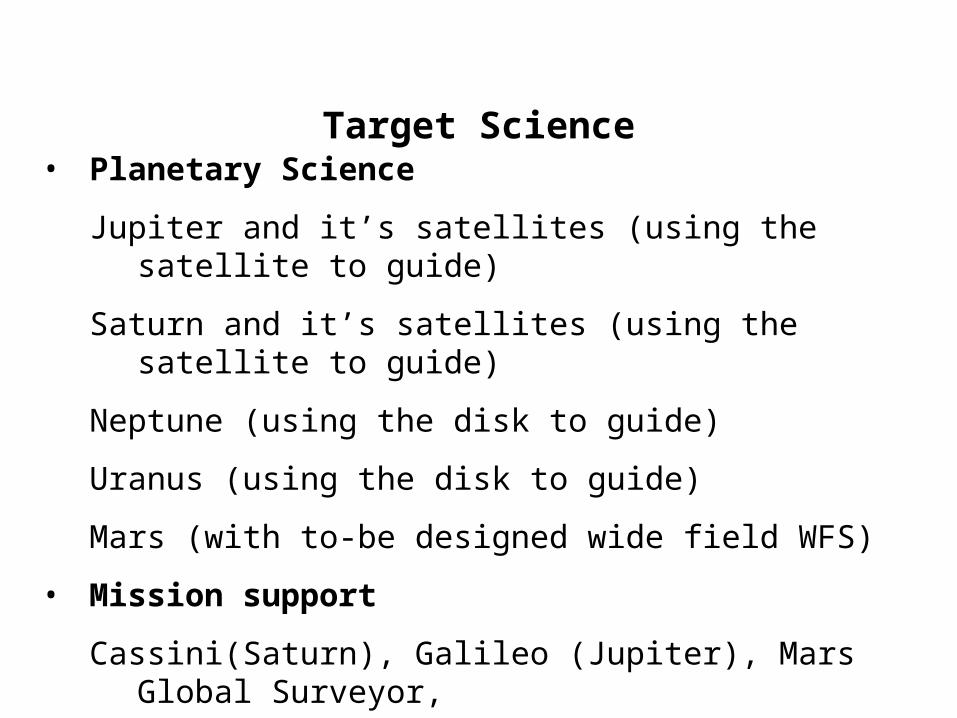
• Planetary Science
Jupiter and it’s satellites (using the satellite to guide)
Saturn and it’s satellites (using the satellite to guide)
Neptune (using the disk to guide)
Uranus (using the disk to guide)
Mars (with to-be designed wide field WFS)
• Mission support
Cassini(Saturn), Galileo (Jupiter), Mars Global Surveyor,
Mars 2001
Target Science
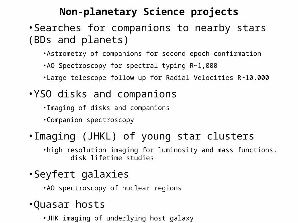
•Searches for companions to nearby stars (BDs and planets)•Astrometry of companions for second epoch confirmation
•AO Spectroscopy for spectral typing R~1,000
•Large telescope follow up for Radial Velocities R~10,000
•YSO disks and companions•Imaging of disks and companions
•Companion spectroscopy
•Imaging (JHKL) of young star clusters•high resolution imaging for luminosity and mass functions, disk lifetime studies
•Seyfert galaxies•AO spectroscopy of nuclear regions
•Quasar hosts•JHK imaging of underlying host galaxy
Non-planetary Science projects
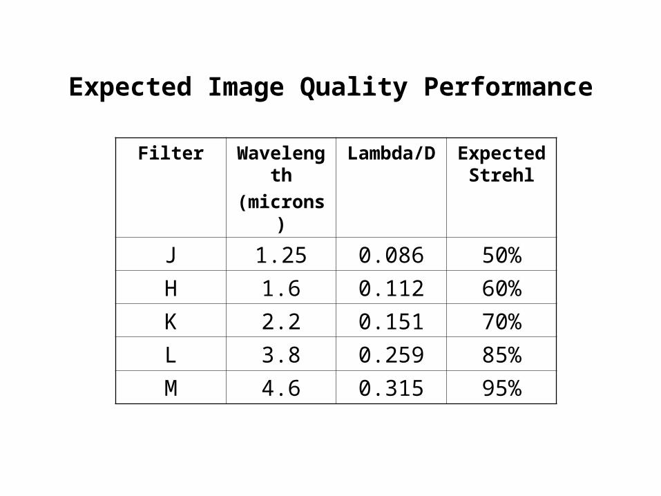
Filter Wavelength
(microns)
Lambda/D Expected Strehl
J 1.25 0.086 50%
H 1.6 0.112 60%
K 2.2 0.151 70%
L 3.8 0.259 85%
M 4.6 0.315 95%
Expected Image Quality Performance
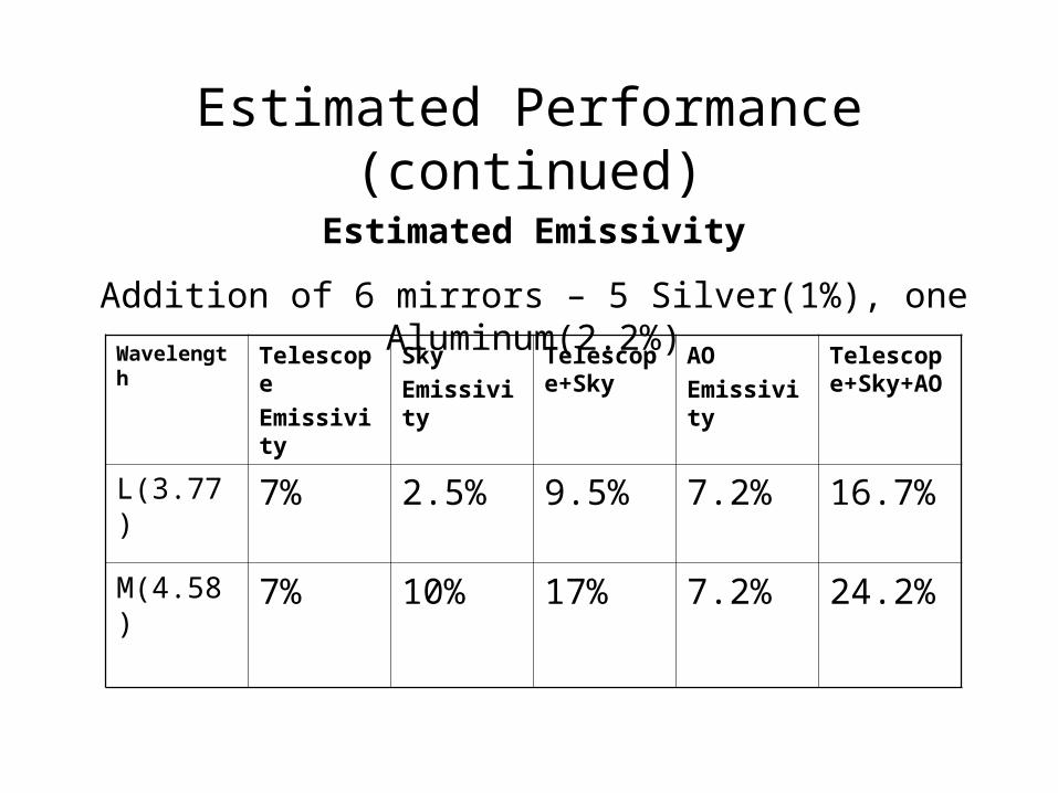
Estimated Emissivity
Addition of 6 mirrors – 5 Silver(1%), one Aluminum(2.2%)
Wavelength Telescope
Emissivity
Sky
Emissivity
Telescope+Sky
AO
Emissivity
Telescope+Sky+AO
L(3.77) 7% 2.5% 9.5% 7.2% 16.7%
M(4.58) 7% 10% 17% 7.2% 24.2%
Estimated Performance (continued)

Estimated Performance(continued)
Sensitivity Limits
•Full AO correction, average to good night, within 30 degrees
of zenith is expected to 12-13th visual magnitude
•Partial AO correction out to 15th magnitude with a gradual
decrease in performance.
•Tip/tilt only correction to 16th
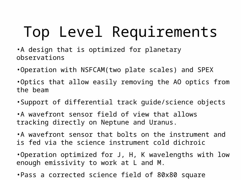
•A design that is optimized for planetary observations
•Operation with NSFCAM(two plate scales) and SPEX
•Optics that allow easily removing the AO optics from the beam
•Support of differential track guide/science objects
•A wavefront sensor field of view that allows tracking directly on Neptune and Uranus.
•A wavefront sensor that bolts on the instrument and is fed via the science instrument cold dichroic
•Operation optimized for J, H, K wavelengths with low enough emissivity to work at L and M.
•Pass a corrected science field of 80x80 square
Top Level Requirements
Desirable Features
• Easy changing between platescales on NSFCAM
• WFS optics that allow IR wavefront sensors in the future.
• Guide camera w/visible Photometry capability
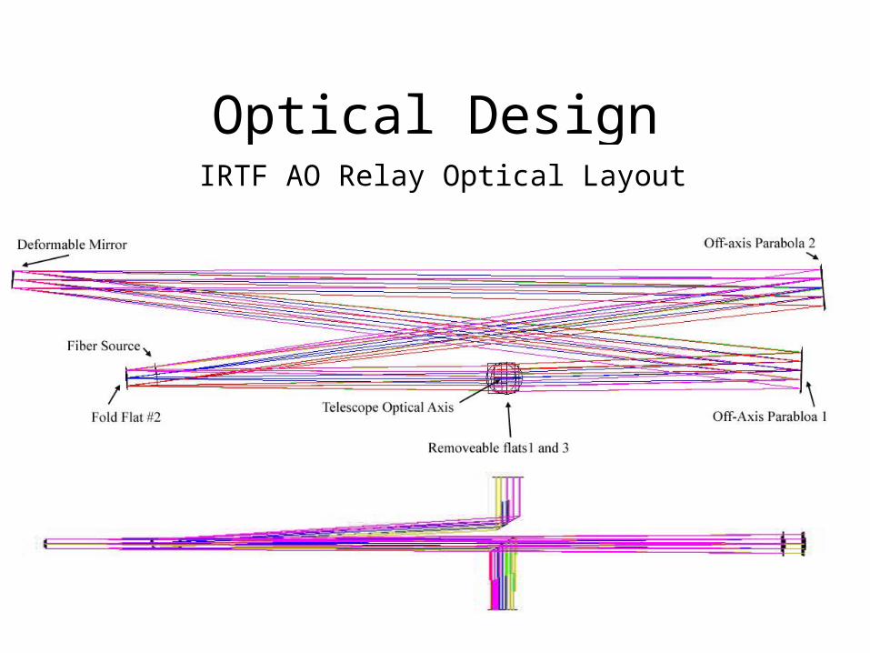
Optical DesignIRTF AO Relay Optical Layout

Optical DesignWavefront Sensor
Optical Performance
Relay performance ~96% Strehl over the 80 arcsecond field
WFS performance ~95% on axis to ~80% in the corners at visible wavelengths
Relay optics specified at Lambda/20 in the visible to reduce scatter to below the atmospheric scatter.
AO Components
• Dan

AO SYSTEM NASA IRTF
MECHANICALSECTION
Vern Stahlberger
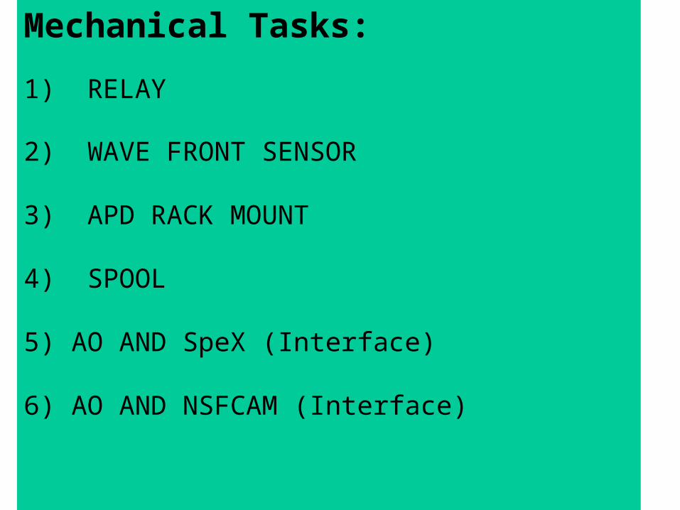
Mechanical Tasks:
1) RELAY
2) WAVE FRONT SENSOR
3) APD RACK MOUNT
4) SPOOL
5) AO AND SpeX (Interface)
6) AO AND NSFCAM (Interface)
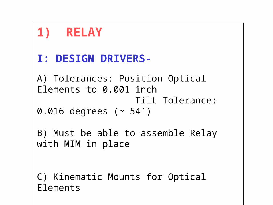
1) RELAY
I: DESIGN DRIVERS-
A) Tolerances: Position Optical Elements to 0.001 inch Tilt Tolerance: 0.016 degrees (~ 54’)
B) Must be able to assemble Relay with MIM in place
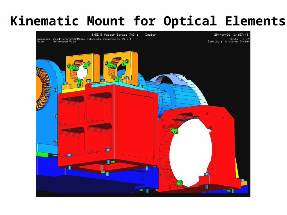
C) Kinematic Mounts for Optical Elements
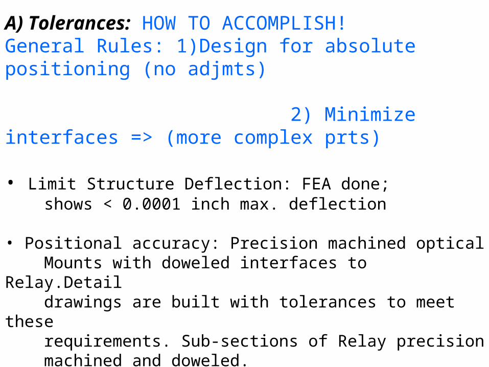
A) Tolerances: HOW TO ACCOMPLISH!General Rules: 1)Design for absolute positioning (no adjmts) 2) Minimize interfaces => (more complex prts)
• Limit Structure Deflection: FEA done; shows < 0.0001 inch max. deflection • Positional accuracy: Precision machined optical Mounts with doweled interfaces to Relay.Detail drawings are built with tolerances to meet these requirements. Sub-sections of Relay precision machined and doweled.
• Tilt tolerance of 0.016 degree (~ one minute) The tolerances on the optics mounts are well within these specifications.
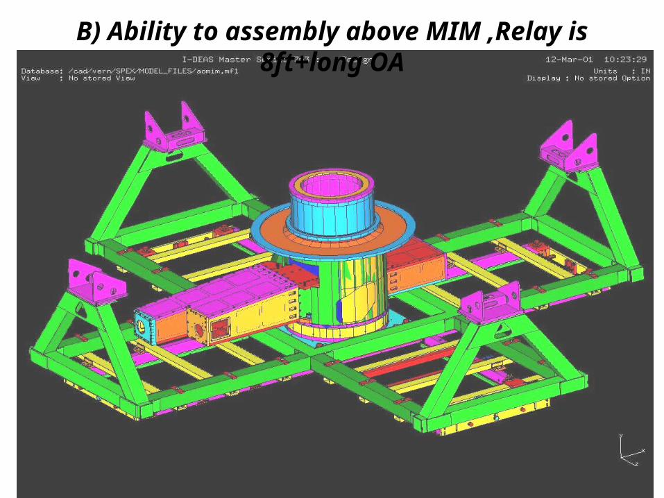
B) Ability to assembly above MIM ,Relay is 8ft+long OA

RELAY SUB-SECTIONS

C) Kinematic Mounts for Optical elements (Flat2)
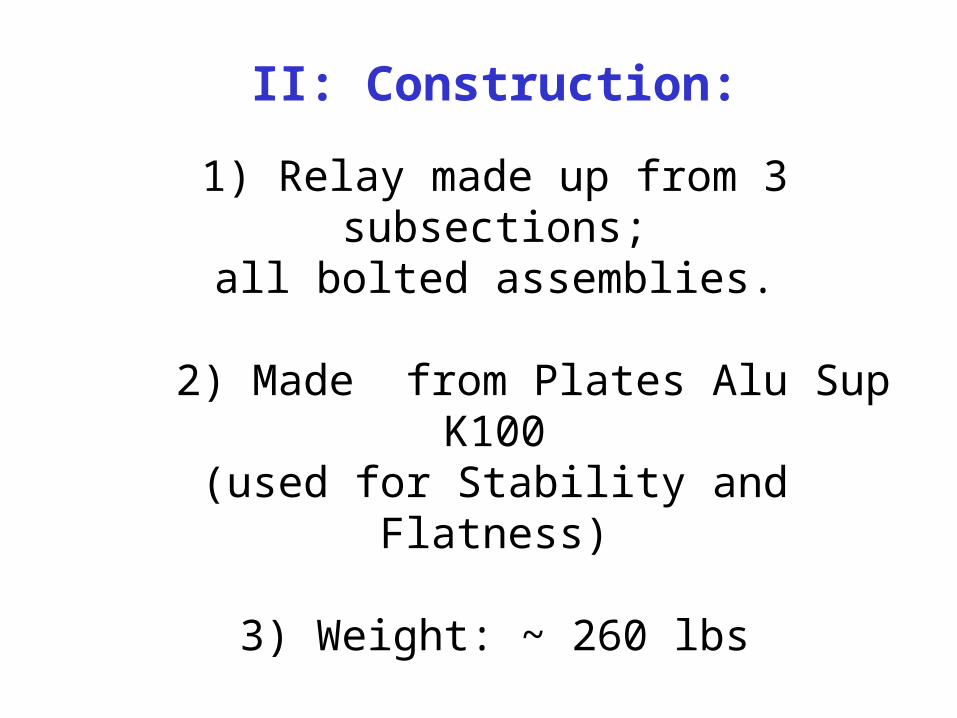
II: Construction:
1) Relay made up from 3 subsections;all bolted assemblies.
2) Made from Plates Alu Sup K100(used for Stability and Flatness)
3) Weight: ~ 260 lbs
4) Overall Dimensions: 101 x 21 x 12 inches
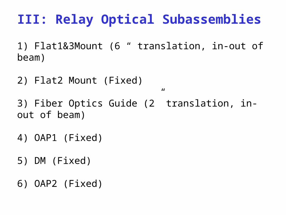
III: Relay Optical Subassemblies
1) Flat1&3Mount (6 “ translation, in-out of beam)
2) Flat2 Mount (Fixed)
3) Fiber Optics Guide (2” translation, in-out of beam)
4) OAP1 (Fixed)
5) DM (Fixed)
6) OAP2 (Fixed)
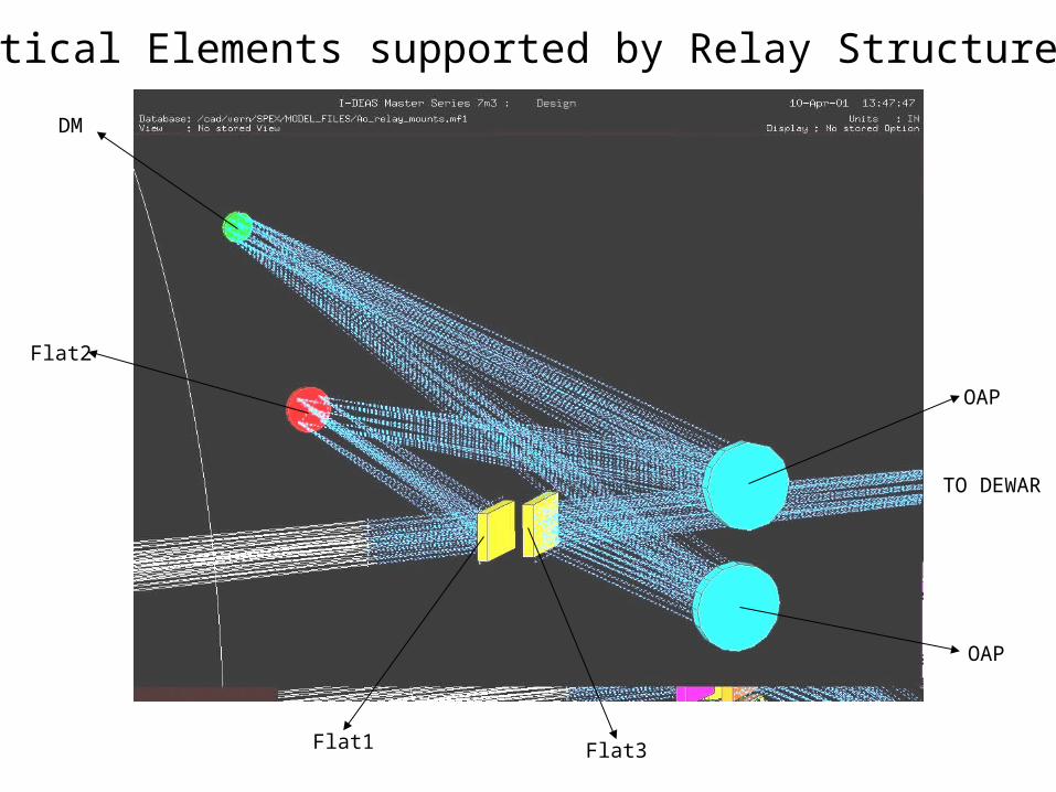
DM
Flat2
Flat1 Flat3
OAP
Optical Elements supported by Relay Structure
OAP
TO DEWAR
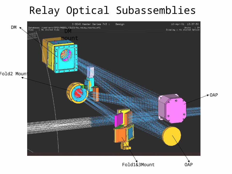
DM mount
OAP
DM
Fold1&3Mount
Fold2 Mount
OAP
Relay Optical Subassemblies

Interfaces: doweled/bolted
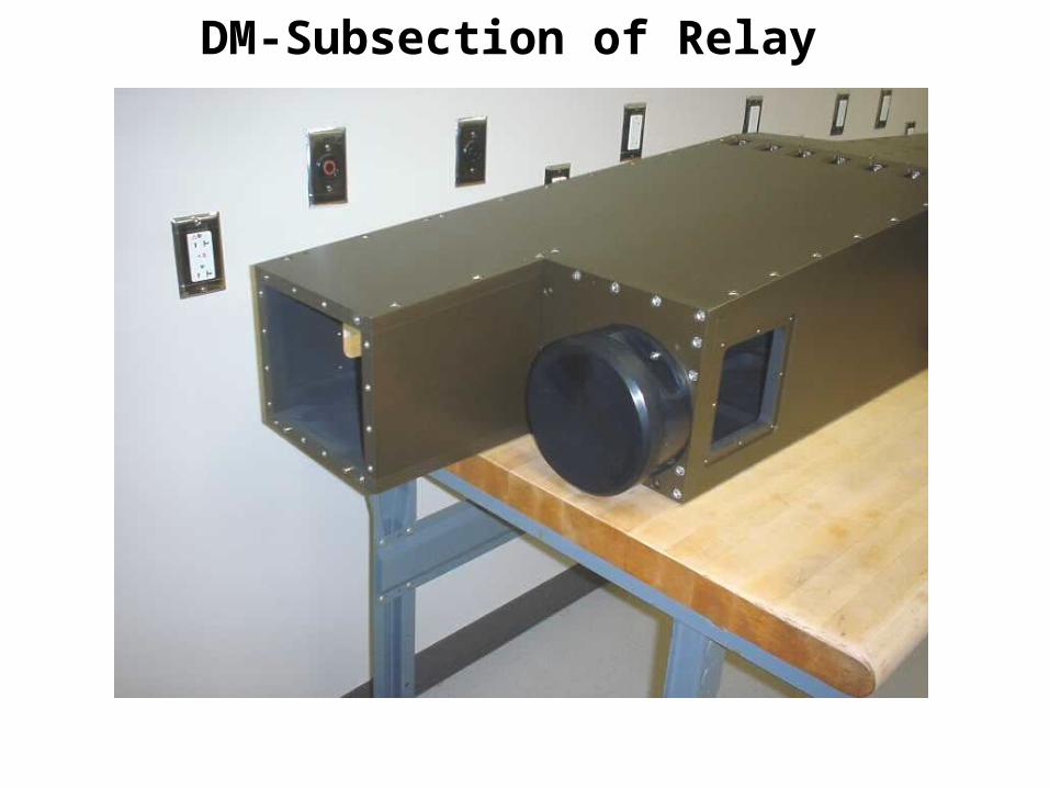
DM-Subsection of Relay
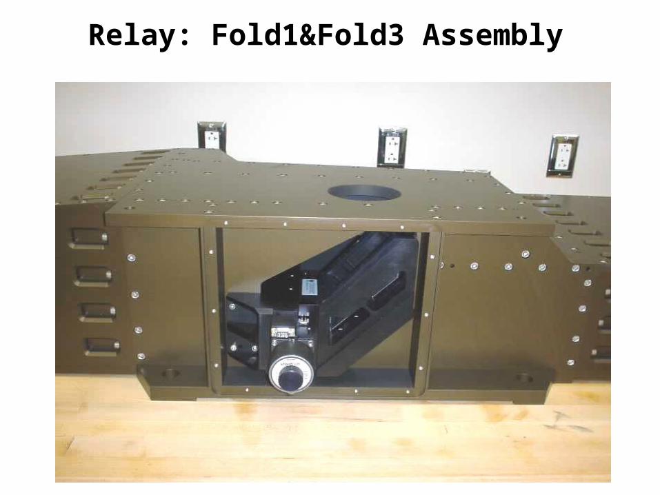
Relay: Fold1&Fold3 Assembly
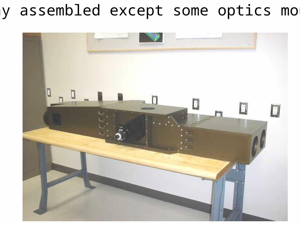
Relay assembled except some optics mounts
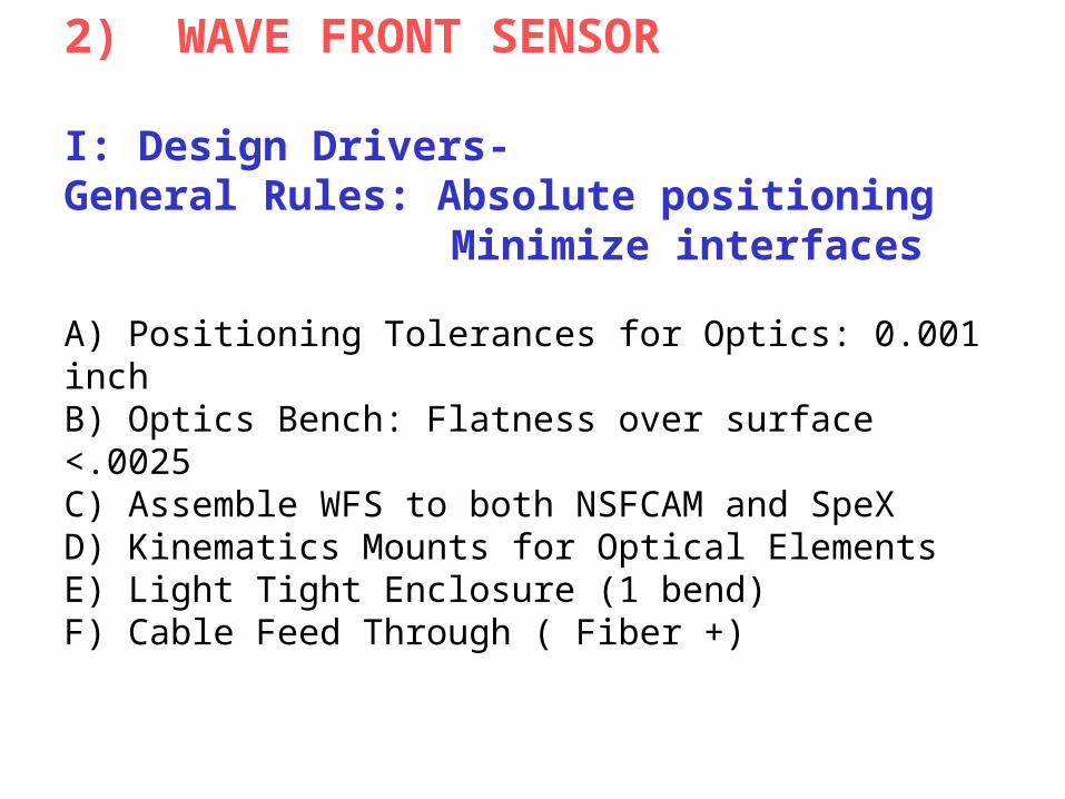
2) WAVE FRONT SENSOR
I: Design Drivers-General Rules: Absolute positioning
Minimize interfaces
A) Positioning Tolerances for Optics: 0.001 inchB) Optics Bench: Flatness over surface <.0025C) Assemble WFS to both NSFCAM and SpeXD) Kinematics Mounts for Optical ElementsE) Light Tight Enclosure (1 bend)F) Cable Feed Through ( Fiber +)
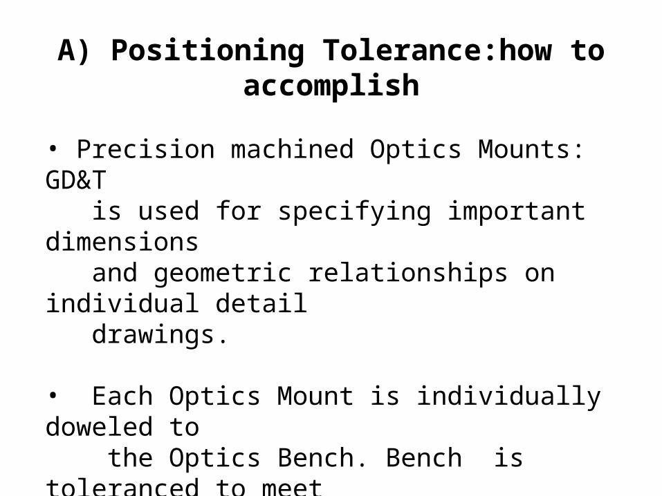
A) Positioning Tolerance:how to accomplish
• Precision machined Optics Mounts: GD&T is used for specifying important dimensions and geometric relationships on individual detail drawings.
• Each Optics Mount is individually doweled to the Optics Bench. Bench is toleranced to meet specs

Example of kinematic mounting
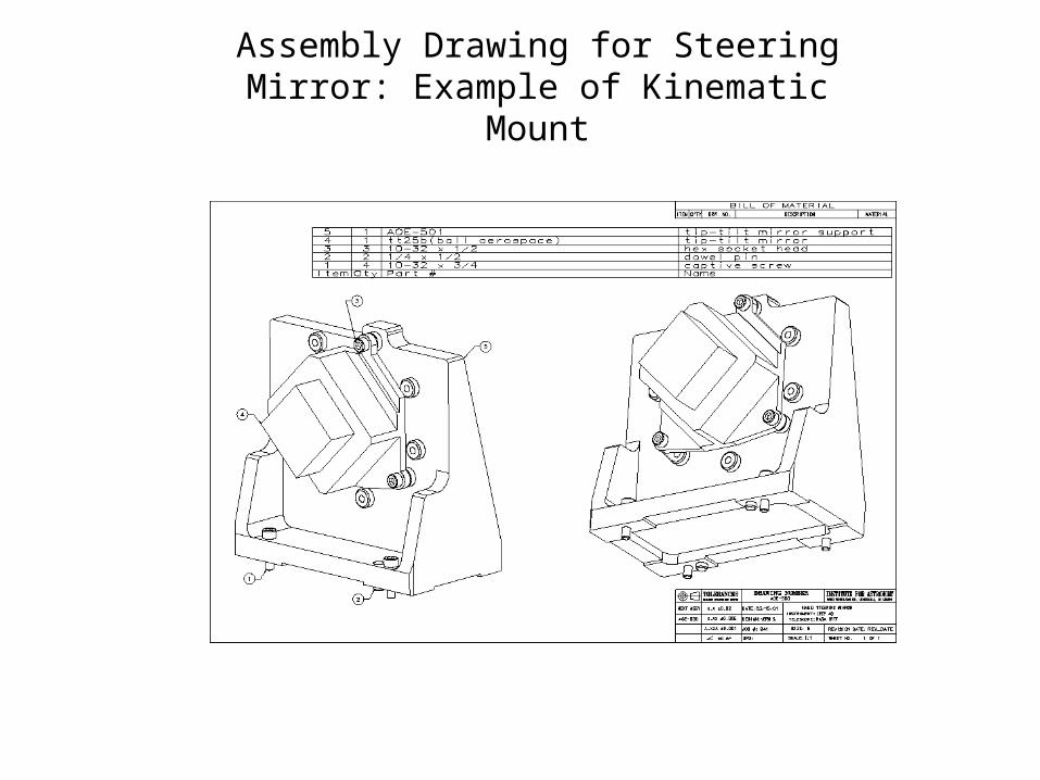
Assembly Drawing for Steering Mirror: Example of Kinematic Mount
B) Optics Bench: (Features)
• Rigidity: Primary concern (to prevent relative platform motion)
• Guaranteed flatness by Vendor < 0.0025 inch
• Lightweight Structure: 47 lbs
• Max. Static Deflection 0.001 inch/40lbs load applied at center.
• Dimensions: 44 1/2 x 15 x 2 inch
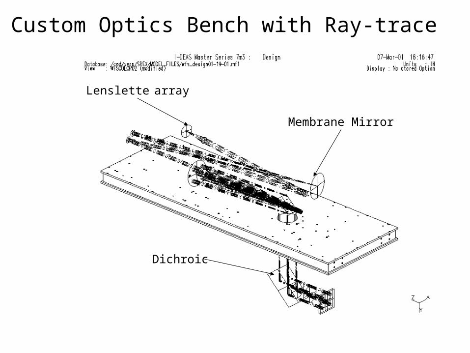
Custom Optics Bench with Ray-trace
Lenslette array
Membrane Mirror
Dichroic

Newport Optics Bench Design:
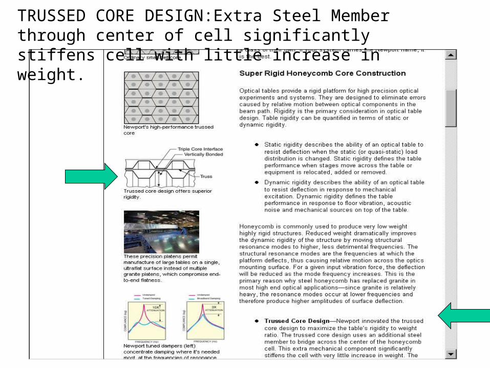
TRUSSED CORE DESIGN:Extra Steel Member through center of cell significantly stiffens cell with little increase in weight.
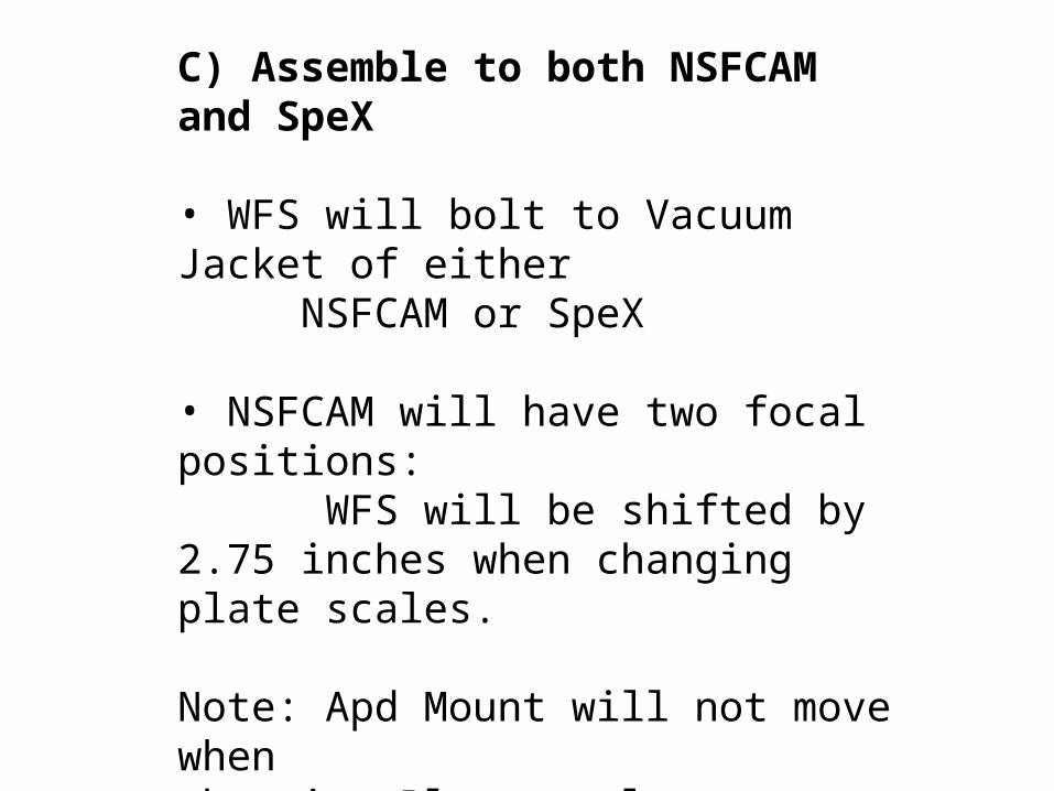
C) Assemble to both NSFCAM and SpeX
• WFS will bolt to Vacuum Jacket of either NSFCAM or SpeX
• NSFCAM will have two focal positions: WFS will be shifted by 2.75 inches when changing plate scales.
Note: Apd Mount will not move whenchanging Plate-scales on NSFCAM. Tie brackets are used to bolt Apd Mount and WFS together only when changinginstruments
D) Kinematic Mount for Optical Elements

E) Light tight Enclosure:Access covers

WFS Optical Subassemblies
3) APD MOUNT
I: Design Drivers-
A) Cool Apd’s + Thermal Managment
B) Need Access to Apd’s for Service/Replacement
C) Need Wire feedthroughs for Fiber and Coax’s
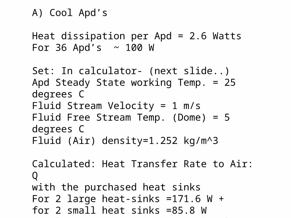
A) Cool Apd’s
Heat dissipation per Apd = 2.6 WattsFor 36 Apd’s ~ 100 W
Set: In calculator- (next slide..)Apd Steady State working Temp. = 25 degrees CFluid Stream Velocity = 1 m/sFluid Free Stream Temp. (Dome) = 5 degrees CFluid (Air) density=1.252 kg/m^3
Calculated: Heat Transfer Rate to Air: Qwith the purchased heat sinksFor 2 large heat-sinks =171.6 W +for 2 small heat sinks =85.8 WTotal Q=257.4 W (Q is proportional to Area of heat sink)

Heat Sinks: Two sizes
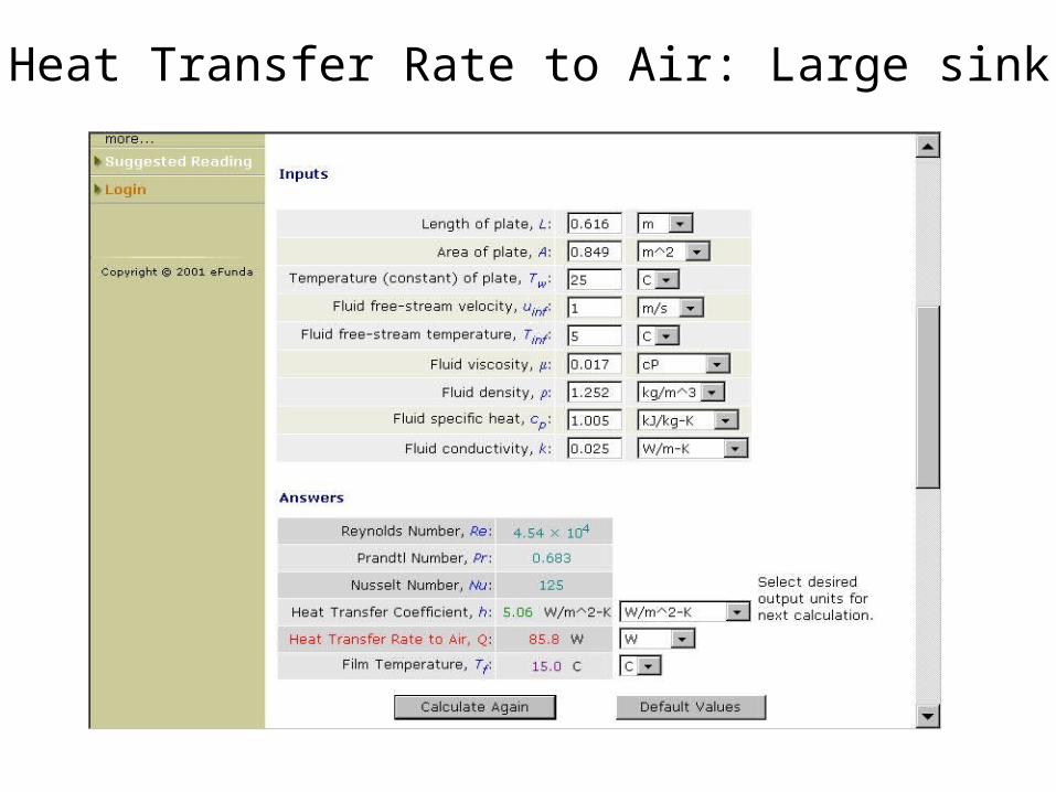
Heat Transfer Rate to Air: Large sink

However….
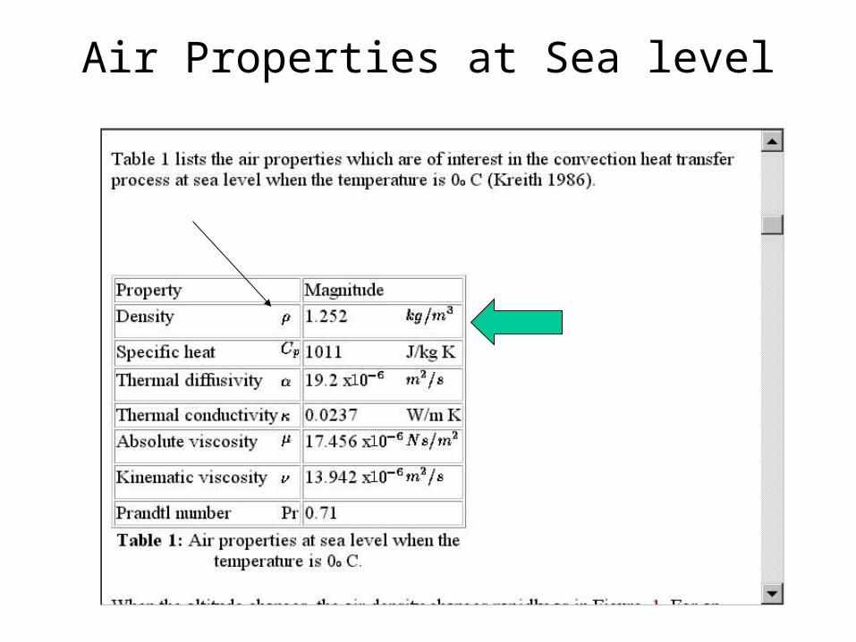
Air Properties at Sea level

Air Properties at 5000 m
Density at 4000m
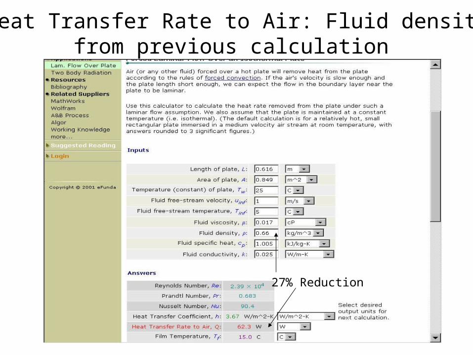
Recalc.Heat Transfer Rate to Air: Fluid density at 50%from previous calculation
27% Reduction
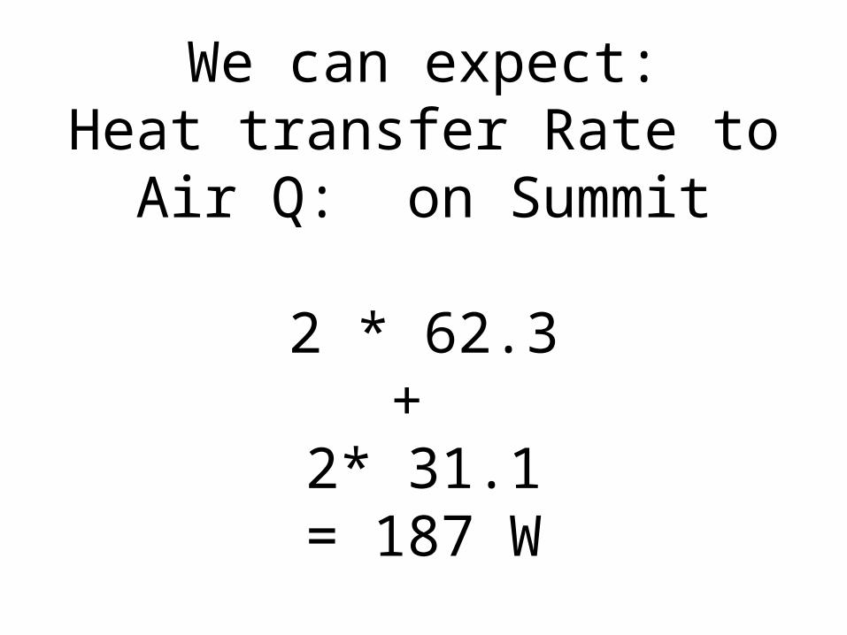
We can expect:Heat transfer Rate to Air Q: on
Summit
2 * 62.3+
2* 31.1= 187 W
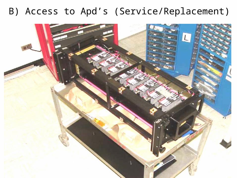
B) Access to Apd’s (Service/Replacement)
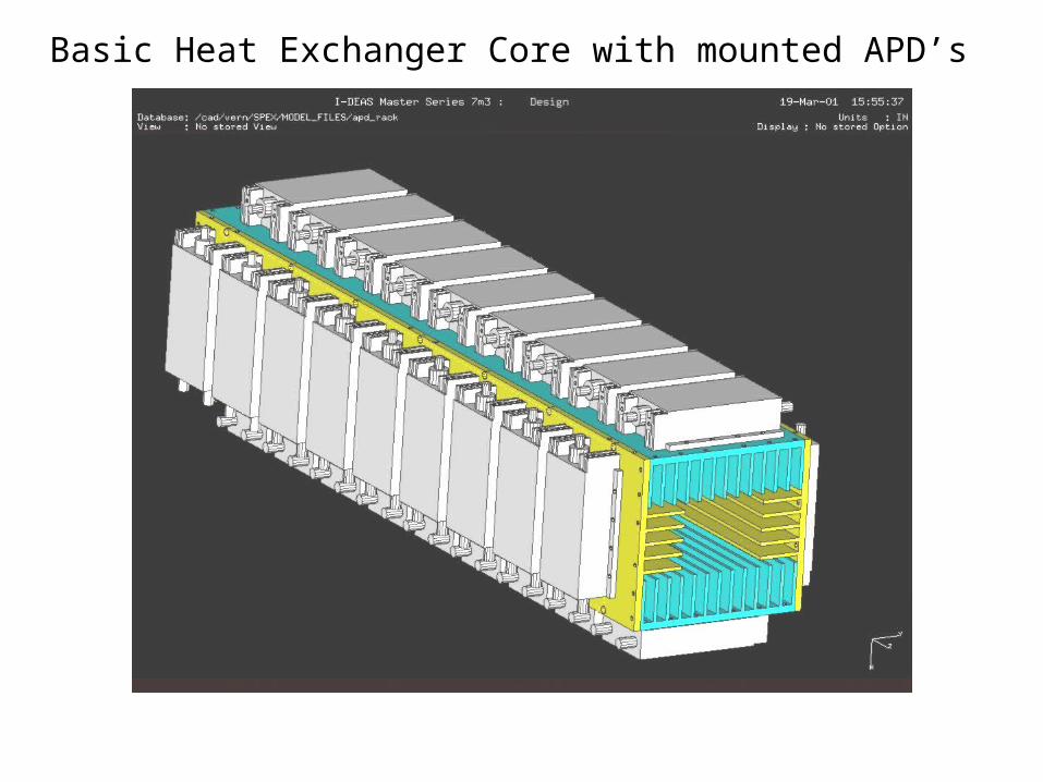
Basic Heat Exchanger Core with mounted APD’s
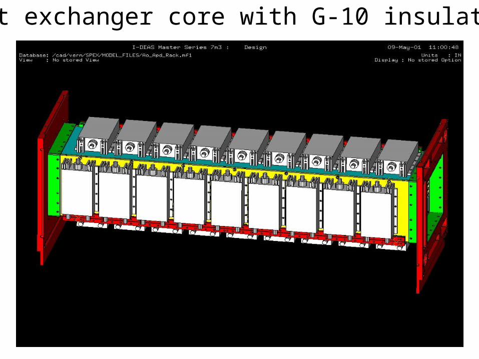
Heat exchanger core with G-10 insulation
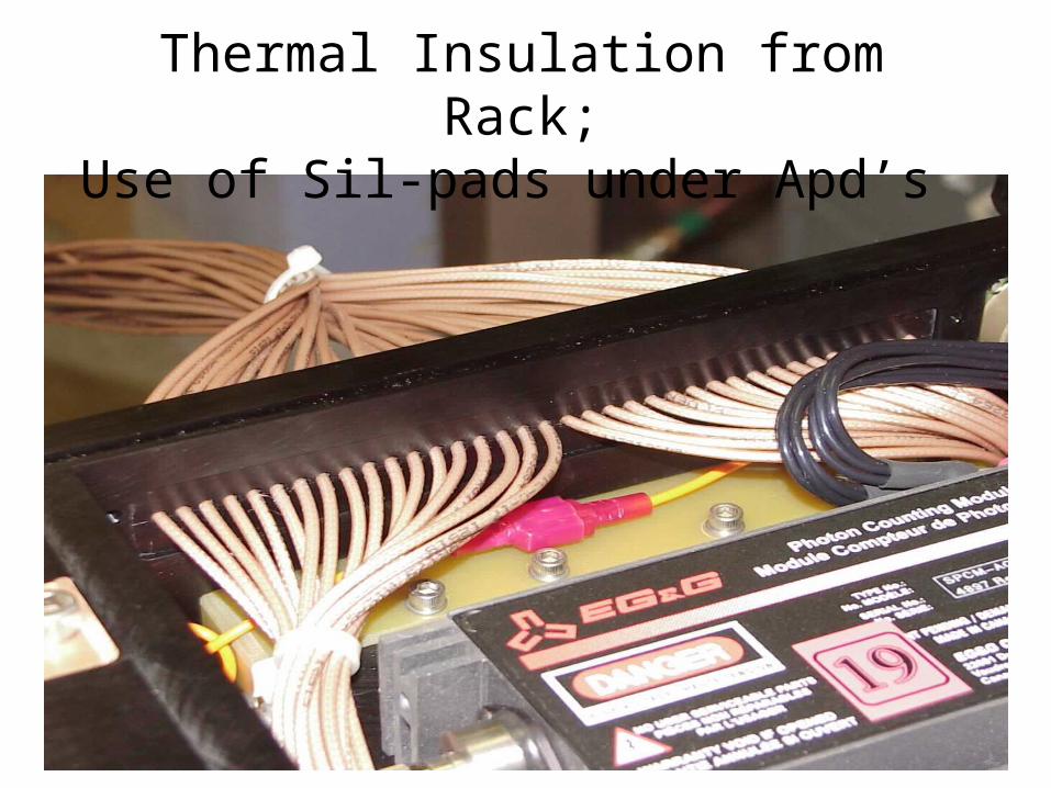
Thermal Insulation from Rack;Use of Sil-pads under Apd’s

Sil-PadsSil-Pads were developed to eliminate
the need for thermal grease. They con-sist on an elastomeric binder com-
pounded with a thermally conductivefiller coated on a carrier.
A typical filler material used isalumina.
On application, the Sil-Pads aremeant to flow under pressure.
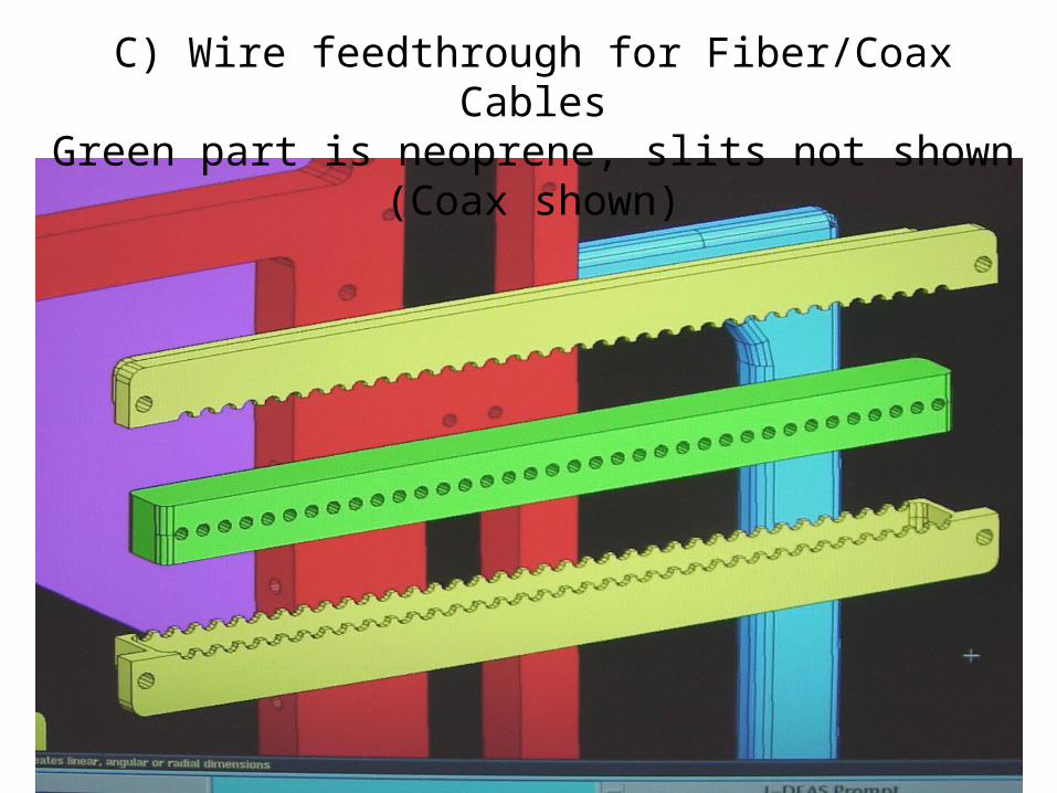
C) Wire feedthrough for Fiber/Coax CablesGreen part is neoprene, slits not shown (Coax shown)
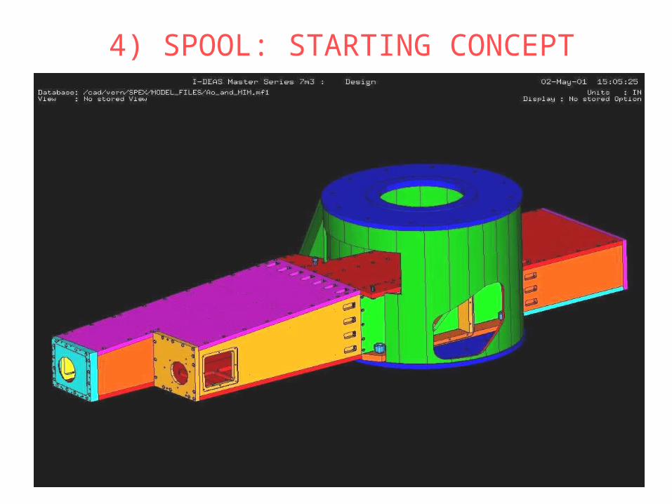
4) SPOOL: STARTING CONCEPT
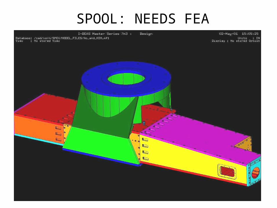
SPOOL: NEEDS FEA
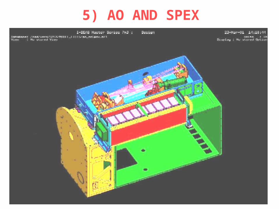
5) AO AND SPEX
Modifications to SpeX:
•Vacuum Jacket: no changes
•Calibration Box: will need3 tapped holes

Apd Rack Mount
SpexCal-Box
VacuumJacket
WFS
SpeX Vacuum Jacket and Cal-box with Ao
Tap 3 holes
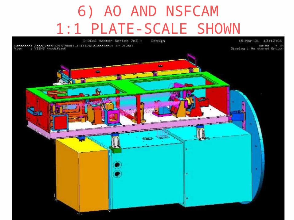
6) AO AND NSFCAM1:1 PLATE-SCALE SHOWN
Modifications to NSFCAM:
• Design is shown for NSFCAM Upgrade:
• Interface Box needs to be redone• Bottom of instrument needs an extension•Note: The AO System can be fitted to•NSFCAM as it exists presently. Holes•will need to be drilled into the VJ.

NSFCAM: 1:1 PLATE-SCALE
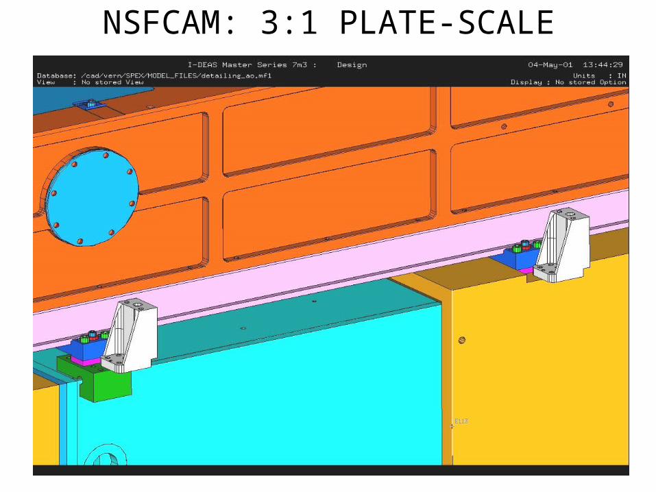
NSFCAM: 3:1 PLATE-SCALE
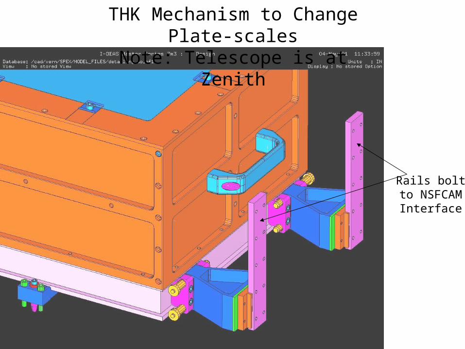
THK Mechanism to Change Plate-scalesNote: Telescope is at Zenith
Rails boltto NSFCAM
Interface
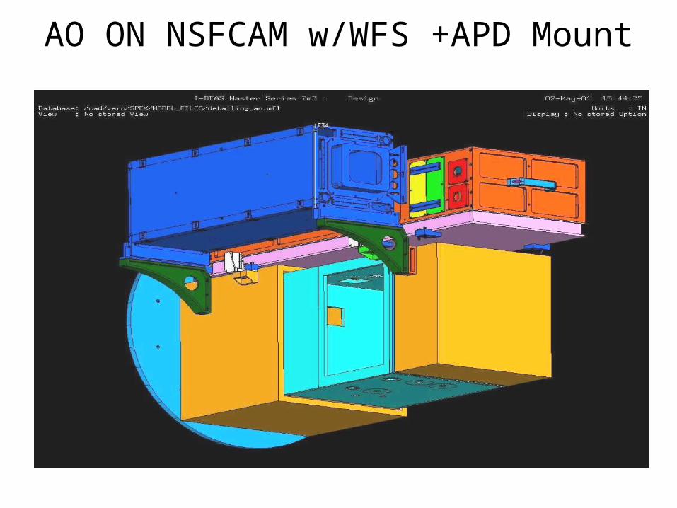
AO ON NSFCAM w/WFS +APD Mount

AO AND NSFCAM: 3:1 PLATESCALE
Shimfor
Adjustm.
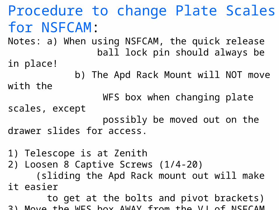
Procedure to change Plate Scales for NSFCAM:Notes: a) When using NSFCAM, the quick release ball lock pin should always be in place! b) The Apd Rack Mount will NOT move with the WFS box when changing plate scales, except possibly be moved out on the drawer slides for access. 1) Telescope is at Zenith2) Loosen 8 Captive Screws (1/4-20) (sliding the Apd Rack mount out will make it easier to get at the bolts and pivot brackets)3) Move the WFS box AWAY from the VJ of NSFCAM.4) Rotate the pivot brackets in or out depending on Plate scale to use5) Make sure the field adjusted spacers are in place6) Bring WFS box in slowly, the tapered pins will help to guide it into proper position.7) Tighten 8 Captive Screws (1/4-20)
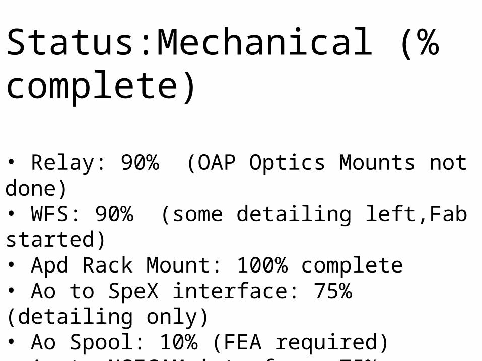
Status:Mechanical (% complete)
• Relay: 90% (OAP Optics Mounts not done)• WFS: 90% (some detailing left,Fab started)• Apd Rack Mount: 100% complete• Ao to SpeX interface: 75% (detailing only)• Ao Spool: 10% (FEA required)• Ao to NSFCAM interface: 75% (detailing only)• Offset Guider/On-axis camera: not started• Handler on Telescope (10%)
AO Electronics
Peter Onaka
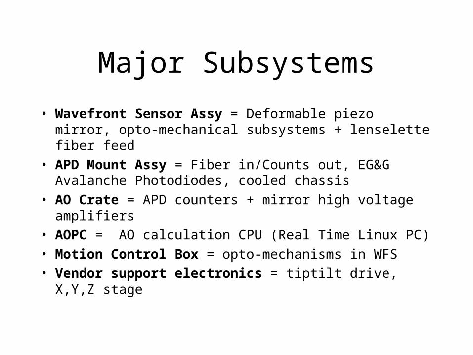
Major Subsystems
• Wavefront Sensor Assy = Deformable piezo mirror, opto-mechanical subsystems + lenselette fiber feed
• APD Mount Assy = Fiber in/Counts out, EG&G Avalanche Photodiodes, cooled chassis
• AO Crate = APD counters + mirror high voltage amplifiers
• AOPC = AO calculation CPU (Real Time Linux PC)
• Motion Control Box = opto-mechanisms in WFS
• Vendor support electronics = tiptilt drive, X,Y,Z stage
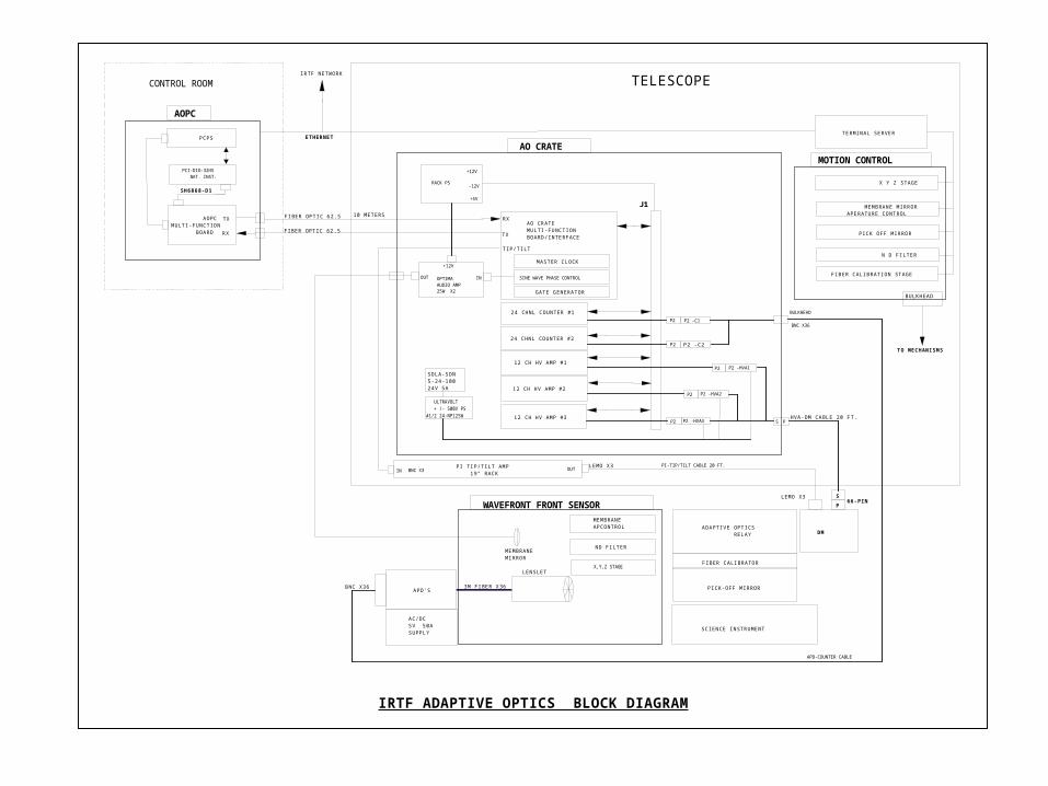
AOPC
PCPS
SOLA-SDN5-24-10024V 5A
ULTRAVOLT + /- 500V PS#1/2 24-NP125W
AOPCMULTI-FUNCTION BOARD
12 CH HV AMP #2
AO CRATEMULTI-FUNCTIONBOARD/INTERFACE
PI TIP/TILT AMP 19" RACK
AC/DC5V 50ASUPPLY
APD'S
J1
WAVEFRONT FRONT SENSORMEMBRANEAPCONTROL
ND FILTER
X,Y,Z STAGE
PICK-OFF MIRROR
FIBER CALIBRATOR
ADAPTIVE OPTICS RELAY DM
MOTION CONTROLAO CRATE
IRTF ADAPTIVE OPTICS BLOCK DIAGRAM
SH6868-D1
SCIENCE INSTRUMENT
X Y Z STAGE
MEMBRANE MIRRORAPERATURE CONTROL
PICK OFF MIRROR
N D FILTER
FIBER CALIBRATION STAGE
12 CH HV AMP #1
12 CH HV AMP #3
24 CHNL COUNTER #1
24 CHNL COUNTER #2
BNC X36
TERMINAL SERVER
CONTROL ROOM TELESCOPE
BULKHEAD
MASTER CLOCK
SINE WAVE PHASE CONTROL
GATE GENERATOR
RX
TX
TX
RX
TIP/TILT
S
P66-PIN
LEMO X3
LEMO X3
LENSLET
MEMBRANEMIRROR
3M FIBER X36
ETHERNET
TO MECHANISMS
IRTF NETWORK
HVA-DM CABLE 20 FT.
10 METERS
PCI-DIO-32HS NAT. INST.
P2 -C1
P2 -C2P2
P2
P2 -HVA1P2
P2 -HVA2P2
P2 -HVA3P2
BULKHEAD
APD-COUNTER CABLE
IN OUT
OPTIMAAUDIO AMP25W X2
RACK PS
+12V
-12V
+5V
PI-TIP/TILT CABLE 20 FT.
OUT IN
+12V
BNC X3
BNC X36
FIBER OPTIC 62.5
FIBER OPTIC 62.5
S P
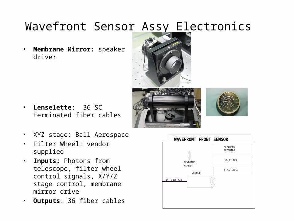
Wavefront Sensor Assy Electronics
• Membrane Mirror: speaker driver
• Lenselette: 36 SC terminated fiber cables
• XYZ stage: Ball Aerospace
• Filter Wheel: vendor supplied
• Inputs: Photons from telescope, filter wheel control signals, X/Y/Z stage control, membrane mirror drive
• Outputs: 36 fiber cables
WAVEFRONT FRONT SENSORMEMBRANEAPCONTROL
ND FILTER
X,Y,Z STAGELENSLET
MEMBRANEMIRROR
3M FIBER X36

APD mount• Cooled housing for 36 EG&G Avalanche
Photo-Diode modules
• Inputs : 36 fiber cables from lenselette array, power for APDs and fans.
• Outputs: 36 APD outputs, temp sensors, thermal cutoff switches.
• Power Dissipation ~100W nominal
AC/DC5V 50ASUPPLY
APD'SBNC X36 3M FIBER X36
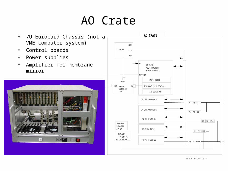
AO Crate• 7U Eurocard Chassis (not a VME
computer system)
• Control boards
• Power supplies
• Amplifier for membrane mirror
SOLA-SDN5-24-10024V 5A
ULTRAVOLT + /- 500V PS#1/2 24-NP125W
12 CH HV AMP #2
AO CRATEMULTI-FUNCTIONBOARD/INTERFACE
J1
AO CRATE
12 CH HV AMP #1
12 CH HV AMP #3
24 CHNL COUNTER #1
24 CHNL COUNTER #2
MASTER CLOCK
SINE WAVE PHASE CONTROL
GATE GENERATOR
RX
TX
TIP/TILT
P2 -C1
P2 -C2P2
P2
P2 -HVA1P2
P2 -HVA2P2
P2 -HVA3P2
OPTIMAAUDIO AMP25W X2
RACK PS
+12V
-12V
+5V
PI-TIP/TILT CABLE 20 FT.
OUT IN
+12V
S P

AO Crate Boards• “remote” Multifunction board
– Fiber interface
– Sinephase Generator = system clock
– Backplane bus interface
• 24 Channel Counter boards x 2– Inputs: APD signals, backplane bus
– Outputs: backplane bus
• 12 Channel High Voltage Amps x 3– Inputs: backplane bus
– Outputs: HV drive to Deformable Mirror

AO Crate I/O • I/O
• Inputs – 36 Coax cables from
APDs
– Fiber from PC MFB
– AC power X 2
• Outputs – HV output cable to DM
– 3 channels of analog drive to PI piezo amplifiers
– Output cable to membrane mirror
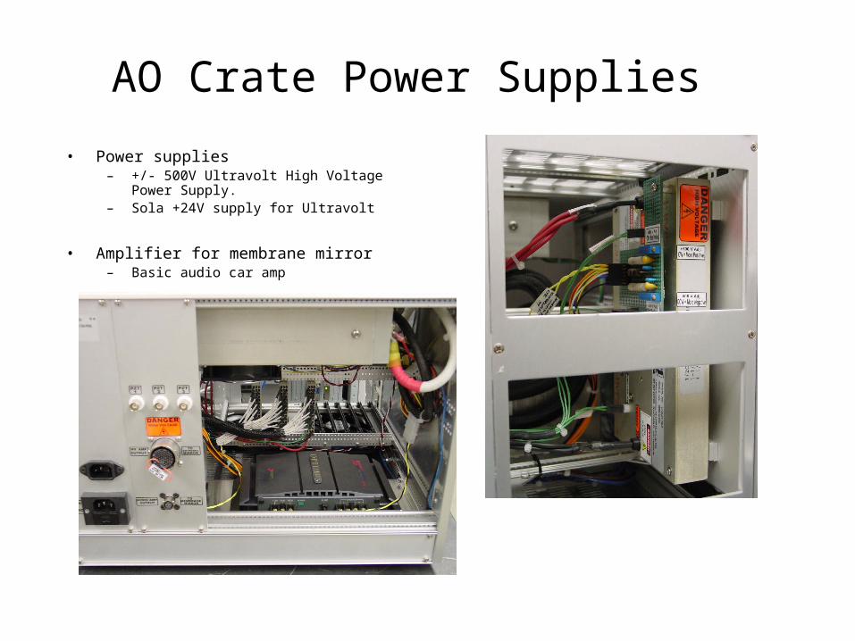
AO Crate Power Supplies
• Power supplies– +/- 500V Ultravolt High Voltage Power
Supply.– Sola +24V supply for Ultravolt
• Amplifier for membrane mirror – Basic audio car amp
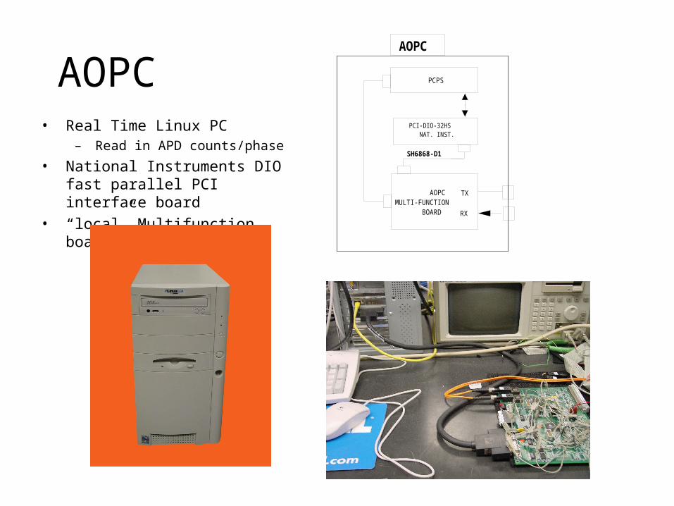
AOPC• Real Time Linux PC
– Read in APD counts/phase
• National Instruments DIO fast parallel PCI interface board
• “local” Multifunction board
AOPC
PCPS
AOPCMULTI-FUNCTION BOARD
SH6868-D1
TX
RX
PCI-DIO-32HS NAT. INST.

Motion Control BoxForm factor TBD• Ball Aerospace control electronics• Filter Wheel control• Physik Instrumente Tiptilt piezo
amplifiers (may be separate assy)• Other mechanisms
MOTION CONTROL
X Y Z STAGE
MEMBRANE MIRRORAPERATURE CONTROL
PICK OFF MIRROR
N D FILTER
FIBER CALIBRATION STAGE
BULKHEAD

Software Tony Denault
Don’t blame me I am new


1. Software Plan A
Zyoptics will give us a copy of their AO software.. Compile & Run!
• Received a port of Hokupa’a from VXWorks/RTLinux (40 % completed).
• Just enough to sample sensor data & check timing. (Does not output to D.Mirror).
• All of the higher level function also commented out.
• Major issues not addressed:– LP_SHMEM – pointers problem.
– Semaphore – resource locking/protections.
• Zyoptics software was configured to their hardware setup – slightly difference from IRTF hardware.
2. Plan B – “Oh no….. what’s plan B?”
Zyoptics software can be used as raw material for IRTF system.
Implement similar structure in RTLinux.
Reverse engineer & import code from zyoptics system to IRTF system.
Implement additional IRTF requirements.
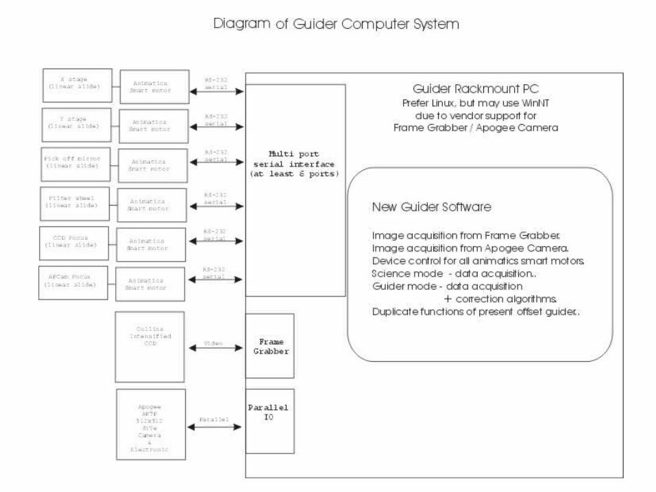
3. The Guider (Porky)
- Detailed Design to be done later. Currently we just have a rough outline of hardware requirements.
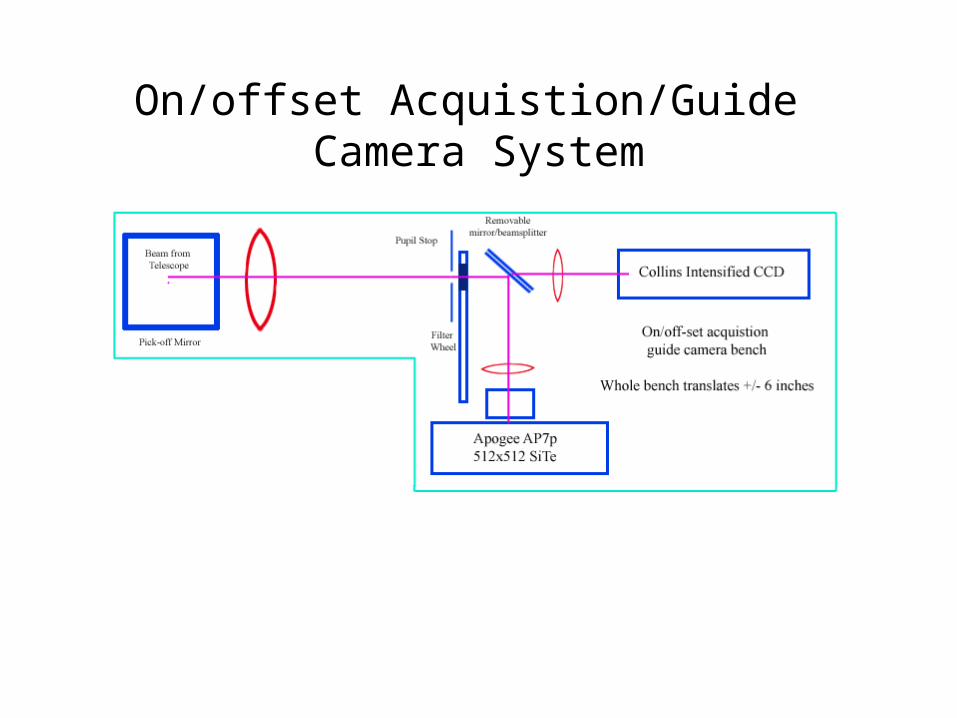
On/offset Acquistion/Guide Camera System
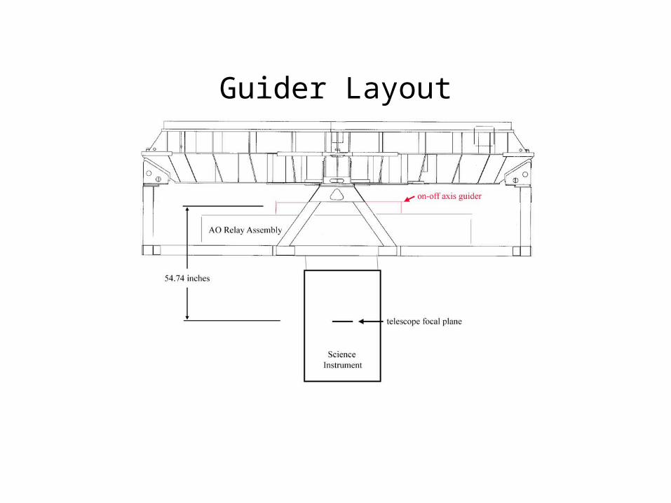
Guider Layout
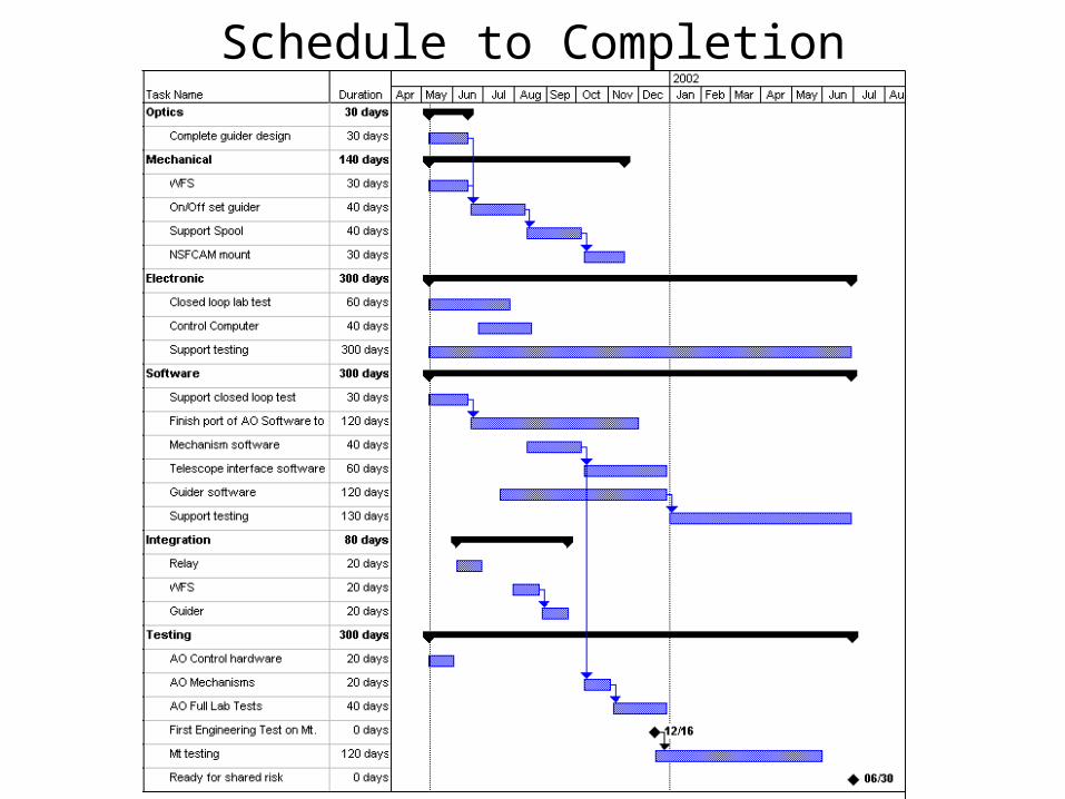
Schedule to Completion
Changes Required for AO Installation
• Relocation of Electronics
• Replacement of On and Off-axis Guiders
• Replacement of NSFCAM’s mount
Changes Desired for AO Installation
• Control of Dome Thermal Environment
• Removal of Electronics Heat
• Control of Astigmatism with the Mirror Bender

The
End