Embed Size (px)
Citation preview
Irradiation of SFR metal fuel in HANARO and the
results of post irradiation examination
2013. 3. 6
Byoung Oon LEE
International Conference on Fast Reactors and Related Fuel
Cycles (FR13), Paris, France

2 2 FR13 13.03.06
OUTLINE
1 Introduction
2
3
4
PIE
Conclusions
HANARO Irradiation
3 3 FR13 13.03.06
INTRODUCTION 1
4 4 FR13 13.03.06
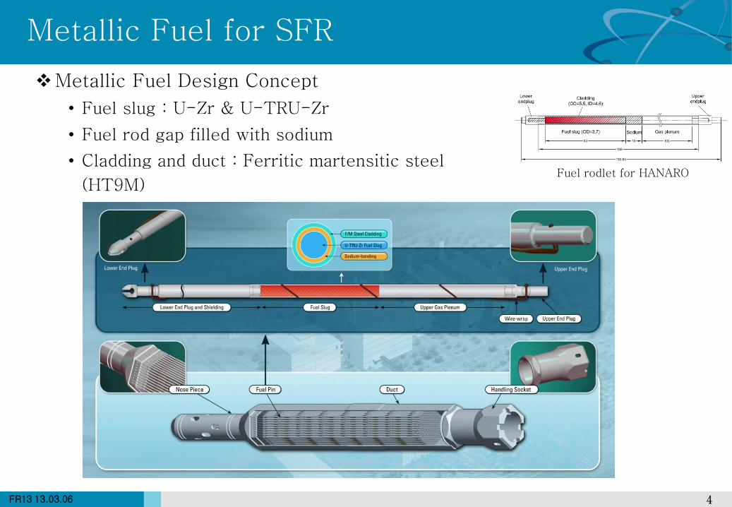
Metallic Fuel for SFR
Metallic Fuel Design Concept
• Fuel slug : U-Zr & U-TRU-Zr
• Fuel rod gap filled with sodium
• Cladding and duct : Ferritic martensitic steel
(HT9M) Fuel rodlet for HANARO
5 5 FR13 13.03.06
SFR Metal Fuel Development Plan
6 6 FR13 13.03.06
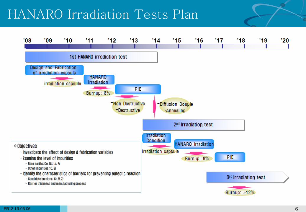
HANARO Irradiation Tests Plan
7 7 FR13 13.03.06
HANARO Irradiation 2
8 8 FR13 13.03.06
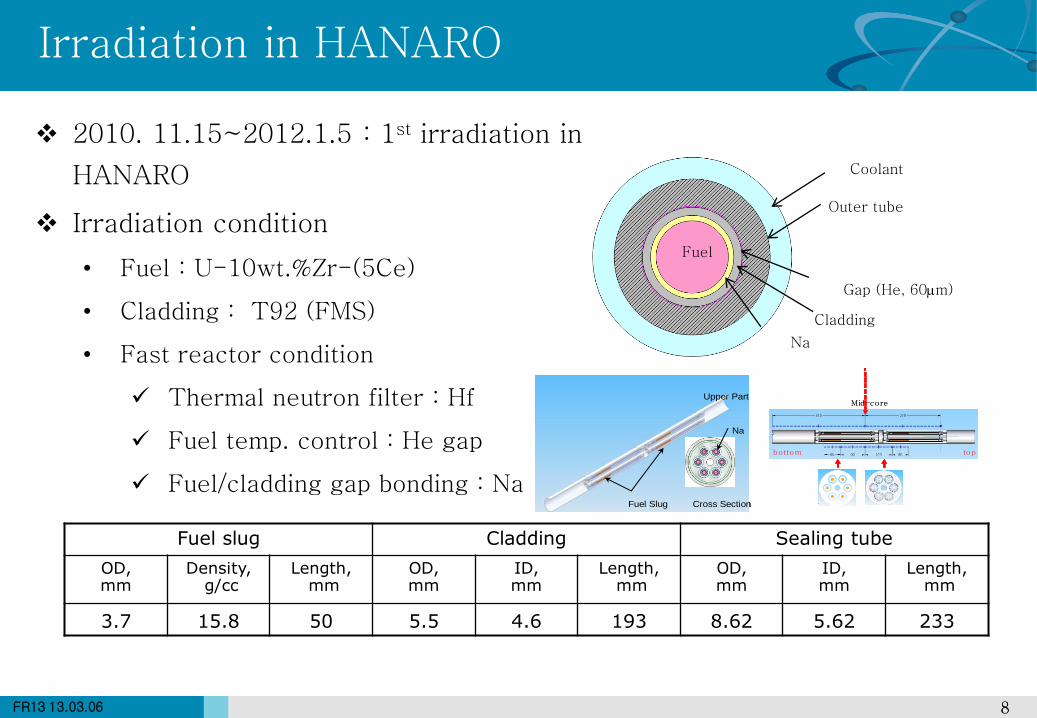
Irradiation in HANARO
Fuel
Na
Outer tube
Gap (He, 60m)
Coolant
Cladding
Fuel slug Cladding Sealing tube
OD, mm
Density, g/cc
Length, mm
OD, mm
ID, mm
Length, mm
OD, mm
ID, mm
Length, mm
3.7 15.8 50 5.5 4.6 193 8.62 5.62 233
2010. 11.15~2012.1.5 : 1st irradiation in
HANARO
Irradiation condition
• Fuel : U-10wt.%Zr-(5Ce)
• Cladding : T92 (FMS)
• Fast reactor condition
Thermal neutron filter : Hf
Fuel temp. control : He gap
Fuel/cladding gap bonding : Na
Fuel Slug Cross Section
Upper Part
Na
Fuel Slug Cross Section
Upper Part
Na
Mid-core
bottom top
Mid-core
bottom top
9 9 FR13 13.03.06
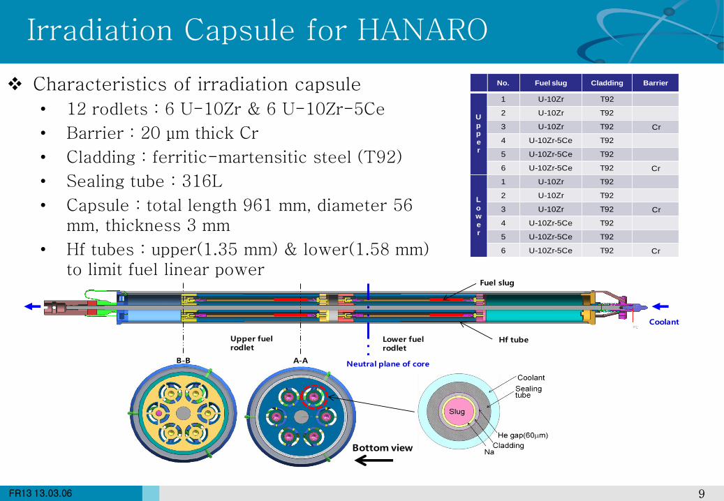
Irradiation Capsule for HANARO
Characteristics of irradiation capsule
• 12 rodlets : 6 U-10Zr & 6 U-10Zr-5Ce
• Barrier : 20 μm thick Cr
• Cladding : ferritic-martensitic steel (T92)
• Sealing tube : 316L
• Capsule : total length 961 mm, diameter 56 mm, thickness 3 mm
• Hf tubes : upper(1.35 mm) & lower(1.58 mm) to limit fuel linear power
Lower fuel rodlet
Upper fuel rodlet
Coolant
Fuel slug
Hf tube
A-AB-B Neutral plane of core
Bottom view
No. Fuel slug Cladding Barrier
U
pp
er
1 U-10Zr T92
2 U-10Zr T92
3 U-10Zr T92 Cr
4 U-10Zr-5Ce T92
5 U-10Zr-5Ce T92
6 U-10Zr-5Ce T92 Cr
L
ow
er
1 U-10Zr T92
2 U-10Zr T92
3 U-10Zr T92 Cr
4 U-10Zr-5Ce T92
5 U-10Zr-5Ce T92
6 U-10Zr-5Ce T92 Cr
10 10 FR13 13.03.06
Evaluation of Irradiation Capsule
Evaluation of Irradiation capsule Integrity
• Fuel integrity is maintained during irradiation : temperature, strain
Cladding inner temperature < 600 C
Conservative LHGR : 352 W/cm
• Out-of-pile tests : satisfied the requirements of the compatibility with the
HANARO
200
250
300
350
400
400
450
500
550
600
650
700
750
800
0 1 2 3 4 5
Lin
ea
r p
ow
er, W
/cm
Te
mp
era
ture
, C
Burnup, at%
Clad inner-wall temp
Centerline temp
LHGR, W/cm
Variation of fuel temperature with burnup
Hf tube
11 11 FR13 13.03.06
HANARO Irradiation History
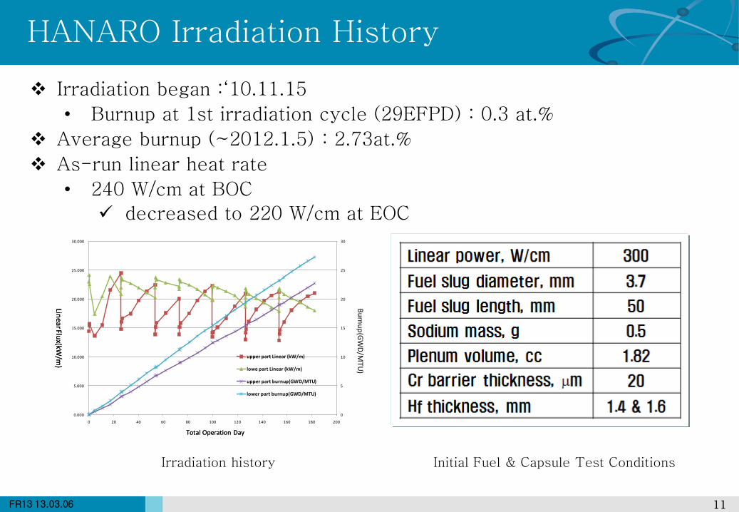
Irradiation began :‘10.11.15
• Burnup at 1st irradiation cycle (29EFPD) : 0.3 at.%
Average burnup (~2012.1.5) : 2.73at.%
As-run linear heat rate
• 240 W/cm at BOC
decreased to 220 W/cm at EOC
Initial Fuel & Capsule Test Conditions Irradiation history
0
5
10
15
20
25
30
0.000
5.000
10.000
15.000
20.000
25.000
30.000
0 20 40 60 80 100 120 140 160 180 200
upper part Linear (kW/m)
lowe part Linear (kW/m)
upper part burnup(GWD/MTU)
lower part burnup(GWD/MTU)
Linear Flu
x(kW/m
)
Total Operation Day
Bu
rnu
p(G
WD
/MTU
)
Linear Flu
x(kW/m
)
Total Operation Day
12 12 FR13 13.03.06
PIE 3
13 13 FR13 13.03.06
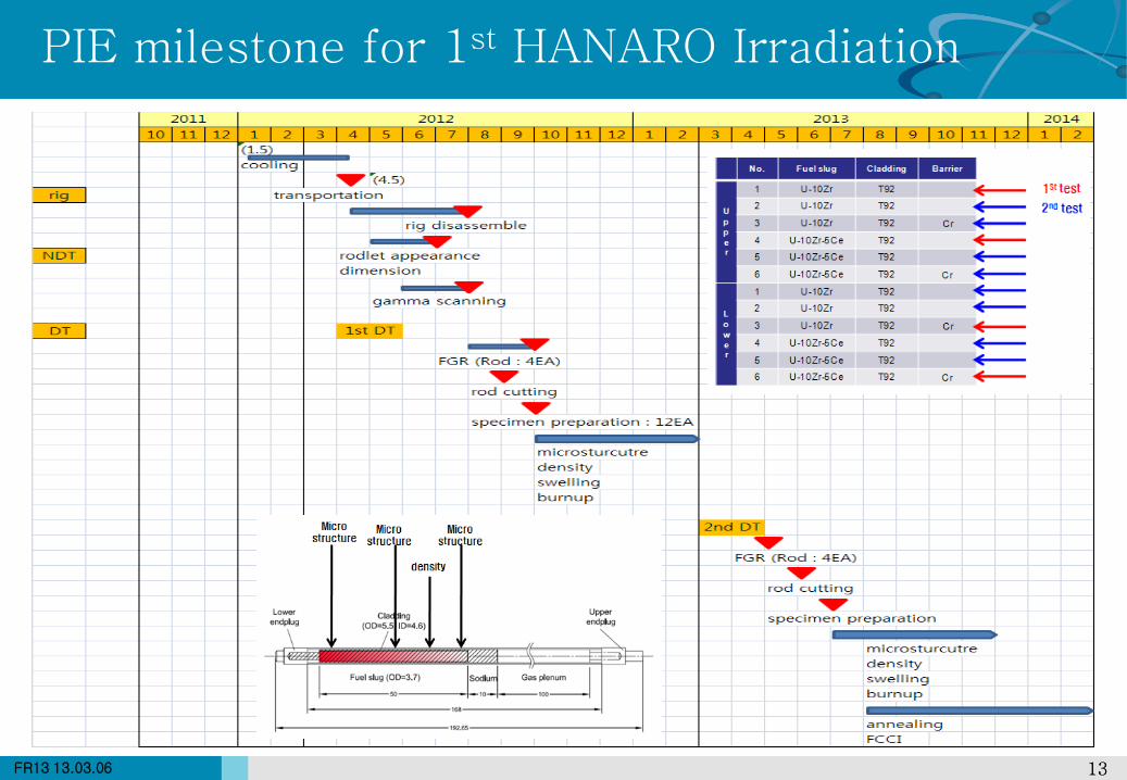
PIE milestone for 1st HANARO Irradiation
14 14 FR13 13.03.06
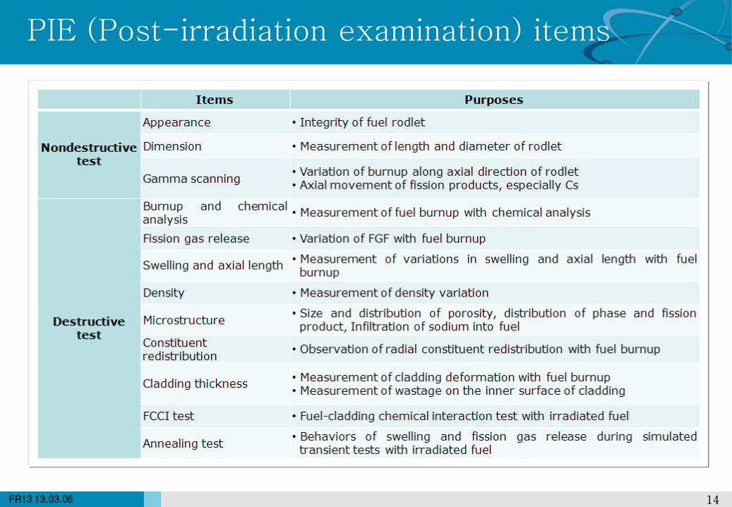
PIE (Post-irradiation examination) items
15 15 FR13 13.03.06
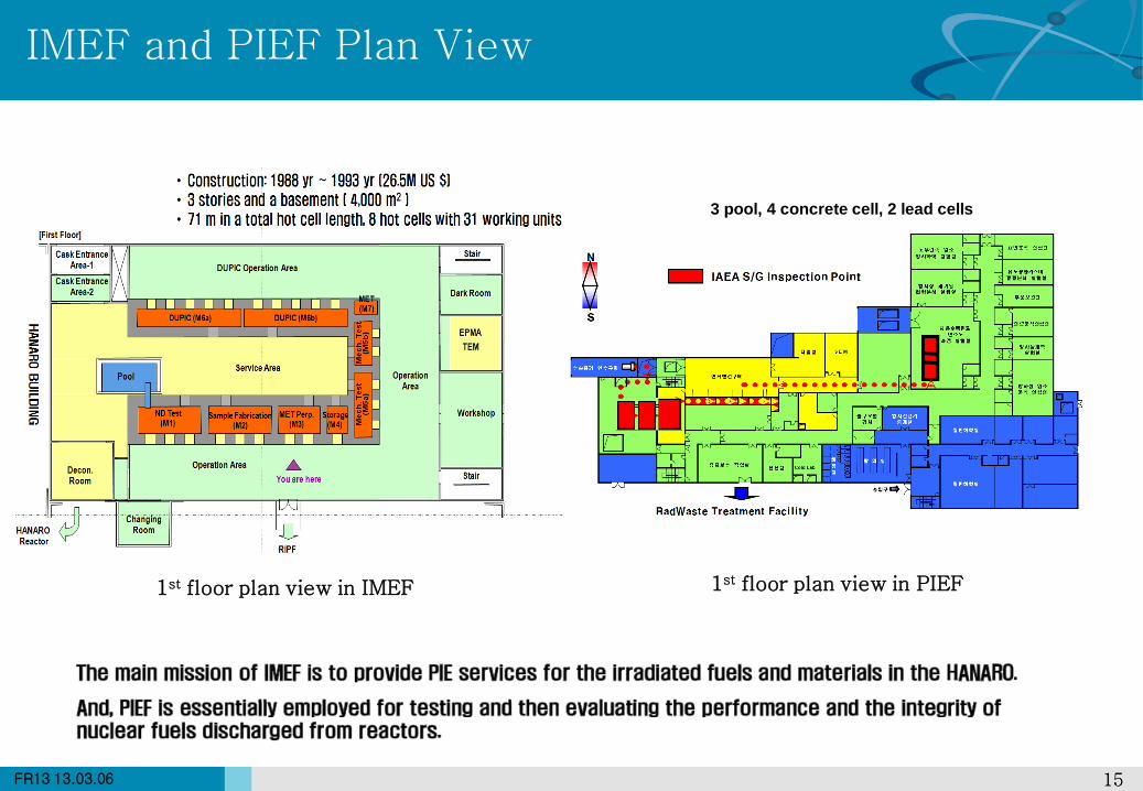
IMEF and PIEF Plan View
1st floor plan view in IMEF 1st floor plan view in PIEF
3 pool, 4 concrete cell, 2 lead cells
16 16 FR13 13.03.06
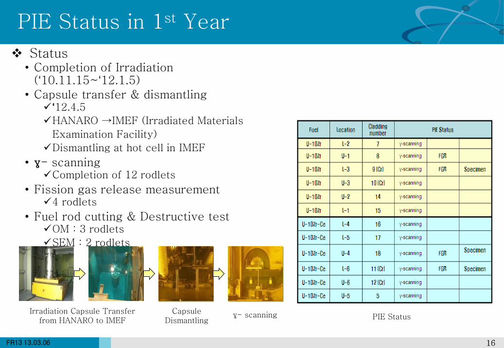
PIE Status in 1st Year
Status • Completion of Irradiation
(‘10.11.15~‘12.1.5) • Capsule transfer & dismantling
‘12.4.5
HANARO →IMEF (Irradiated Materials
Examination Facility)
Dismantling at hot cell in IMEF
• γ- scanning Completion of 12 rodlets
• Fission gas release measurement 4 rodlets
• Fuel rod cutting & Destructive test OM : 3 rodlets
SEM : 2 rodlets
PIE Status Irradiation Capsule Transfer
from HANARO to IMEF Capsule
Dismantling γ- scanning
17 17 FR13 13.03.06
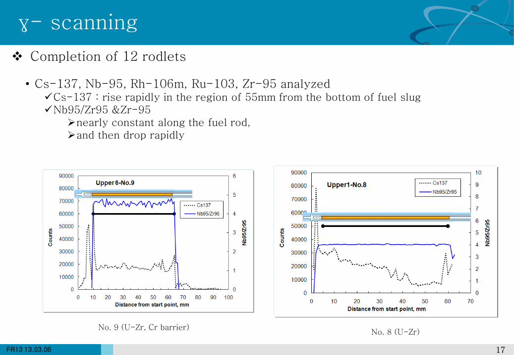
γ- scanning
Completion of 12 rodlets
• Cs-137, Nb-95, Rh-106m, Ru-103, Zr-95 analyzed Cs-137 : rise rapidly in the region of 55mm from the bottom of fuel slug Nb95/Zr95 &Zr-95
nearly constant along the fuel rod, and then drop rapidly
No. 9 (U-Zr, Cr barrier) No. 8 (U-Zr)
18 18 FR13 13.03.06
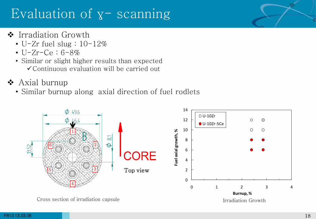
Evaluation of γ- scanning
Irradiation Growth • U-Zr fuel slug : 10-12% • U-Zr-Ce : 6-8% • Similar or slight higher results than expected
Continuous evaluation will be carried out
Axial burnup • Similar burnup along axial direction of fuel rodlets
Irradiation Growth Cross section of irradiation capsule
Top view
1
2
3
6
5
4 0
2
4
6
8
10
12
14
0 1 2 3 4
Fue
l axi
al g
row
th, %
Burnup, %
U-10Zr
U-10Zr-5Ce
19 19 FR13 13.03.06
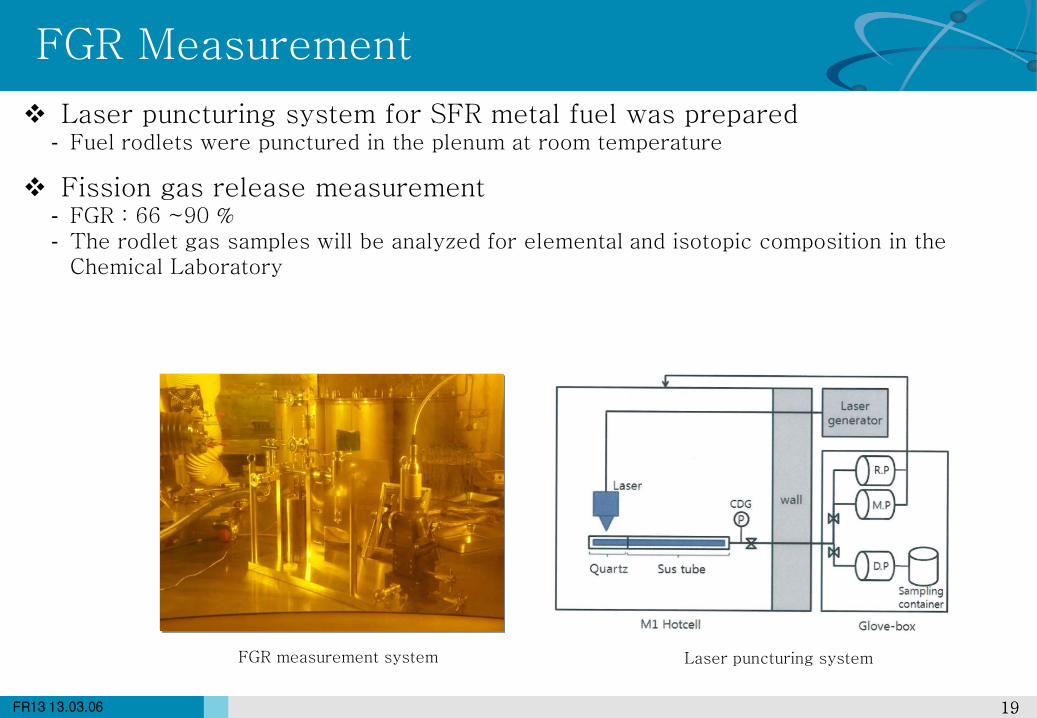
FGR Measurement
Laser puncturing system for SFR metal fuel was prepared - Fuel rodlets were punctured in the plenum at room temperature
Fission gas release measurement - FGR : 66 ~90 % - The rodlet gas samples will be analyzed for elemental and isotopic composition in the
Chemical Laboratory
FGR measurement system Laser puncturing system
20 20 FR13 13.03.06
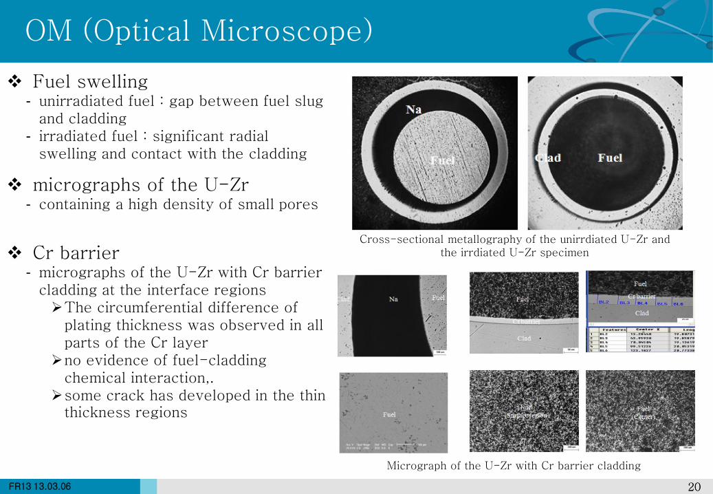
OM (Optical Microscope)
Fuel swelling - unirradiated fuel : gap between fuel slug
and cladding - irradiated fuel : significant radial
swelling and contact with the cladding
micrographs of the U-Zr - containing a high density of small pores
Cr barrier - micrographs of the U-Zr with Cr barrier
cladding at the interface regions The circumferential difference of
plating thickness was observed in all parts of the Cr layer
no evidence of fuel-cladding chemical interaction,.
some crack has developed in the thin thickness regions
Cross-sectional metallography of the unirrdiated U-Zr and the irrdiated U-Zr specimen
Micrograph of the U-Zr with Cr barrier cladding
21 21 FR13 13.03.06
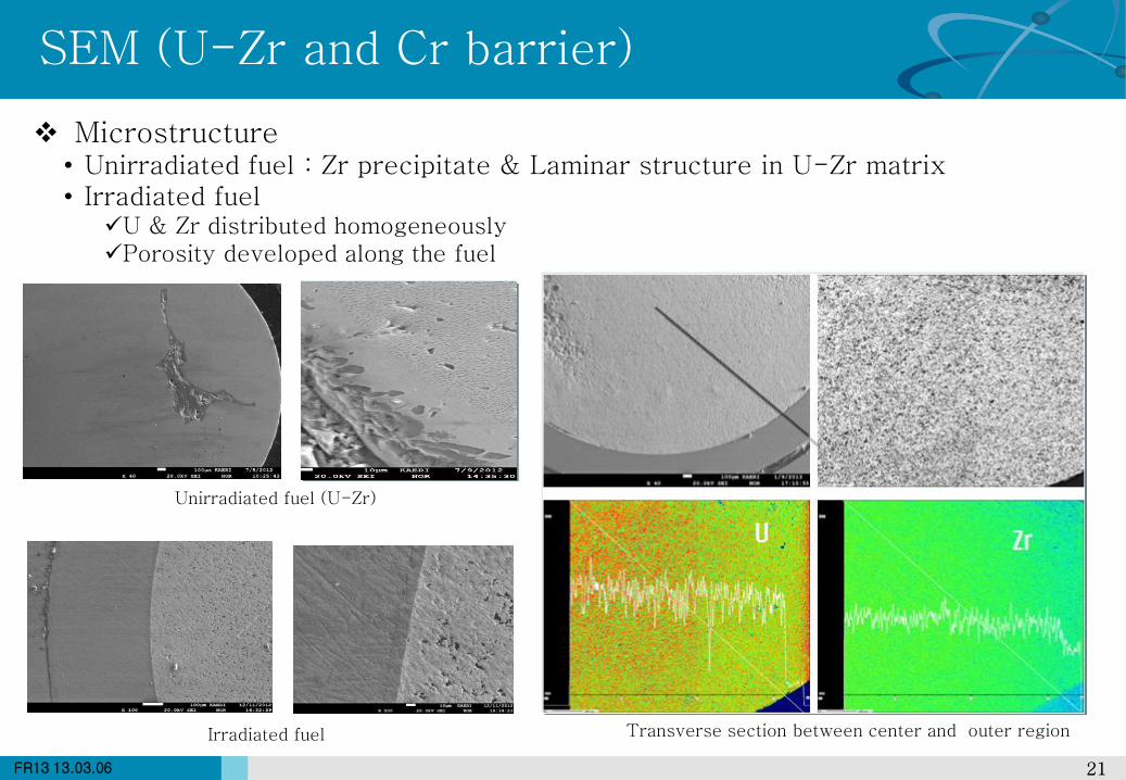
SEM (U-Zr and Cr barrier)
Microstructure • Unirradiated fuel : Zr precipitate & Laminar structure in U-Zr matrix • Irradiated fuel
U & Zr distributed homogeneously Porosity developed along the fuel
Unirradiated fuel (U-Zr)
Irradiated fuel Transverse section between center and outer region
22 22 FR13 13.03.06
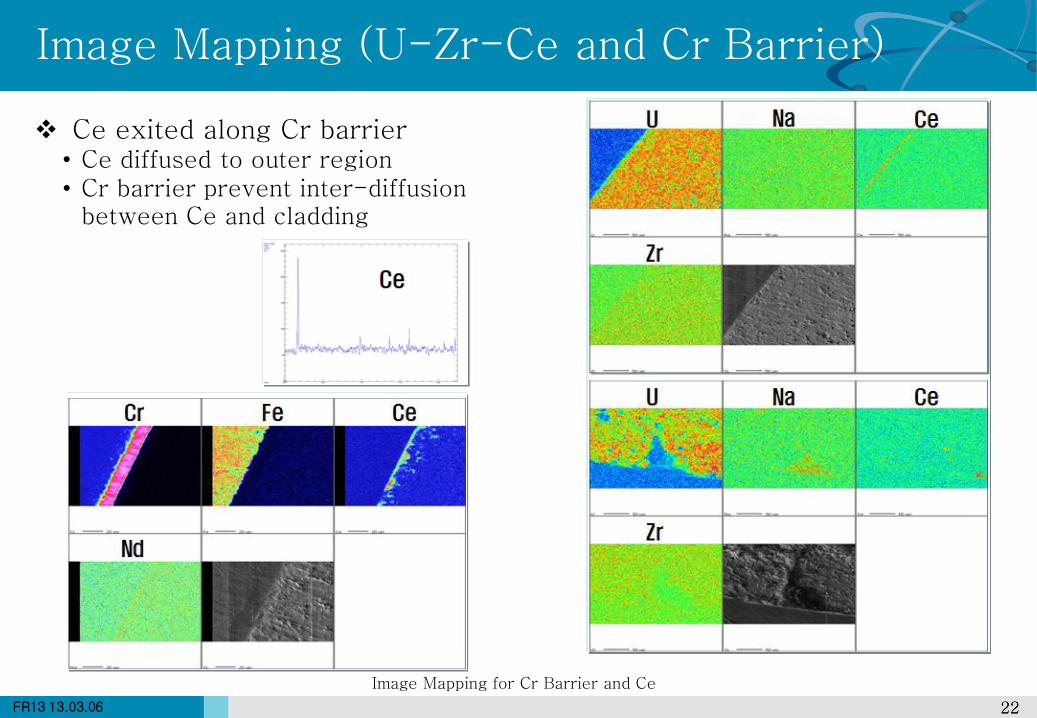
Image Mapping (U-Zr-Ce and Cr Barrier)
Ce exited along Cr barrier • Ce diffused to outer region • Cr barrier prevent inter-diffusion
between Ce and cladding
Image Mapping for Cr Barrier and Ce

23 23 FR13 13.03.06
CONCLUSIONS 4
24 24 FR13 13.03.06
Metallic fuel development for SFR started in 2007
1st HANARO Irradiation : 2010.11 ~2012.1
PIE is being carried out in IMEF from 2012.4
• Gamma scans for twelve metallic fuel rodlets were completed
• The cross-sectional metalography of the irradiated U-Zr specimen shows
significant radial swelling
• Cr barrier cladding at the interface regions show there are no macroscopic
reaction between fuel and cladding
• PIE for 1st HANARO irradiation will be completed in 2014.02
Continuous experimental tests needed
• for the establishment of performance evaluation tools and design data bases
• 2nd HANARO Irradiation : 2014 ~
Conclusions