Embed Size (px)
Citation preview

IR1101 Industrial Integrated Services Router Hardware Installation GuideJanuary 2019
Americas HeadquartersCisco Systems, Inc.170 West Tasman DriveSan Jose, CA 95134-1706 USAhttp://www.cisco.comTel: 408 526-4000
800 553-NETS (6387)Fax: 408 527-0883
Text Part Number:

THE SPECIFICATIONS AND INFORMATION REGARDING THE PRODUCTS IN THIS MANUAL ARE SUBJECT TO CHANGE WITHOUT NOTICE. ALL STATEMENTS, INFORMATION, AND RECOMMENDATIONS IN THIS MANUAL ARE BELIEVED TO BE ACCURATE BUT ARE PRESENTED WITHOUT WARRANTY OF ANY KIND, EXPRESS OR IMPLIED. USERS MUST TAKE FULL RESPONSIBILITY FOR THEIR APPLICATION OF ANY PRODUCTS.
THE SOFTWARE LICENSE AND LIMITED WARRANTY FOR THE ACCOMPANYING PRODUCT ARE SET FORTH IN THE INFORMATION PACKET THAT SHIPPED WITH THE PRODUCT AND ARE INCORPORATED HEREIN BY THIS REFERENCE. IF YOU ARE UNABLE TO LOCATE THE SOFTWARE LICENSE OR LIMITED WARRANTY, CONTACT YOUR CISCO REPRESENTATIVE FOR A COPY.
The following information is for FCC compliance of Class A devices: This equipment has been tested and found to comply with the limits for a Class A digital device, pursuant to part 15 of the FCC rules. These limits are designed to provide reasonable protection against harmful interference when the equipment is operated in a commercial environment. This equipment generates, uses, and can radiate radio-frequency energy and, if not installed and used in accordance with the instruction manual, may cause harmful interference to radio communications. Operation of this equipment in a residential area is likely to cause harmful interference, in which case users will be required to correct the interference at their own expense.
Modifications to this product not authorized by Cisco could void the FCC approval and negate your authority to operate the product.
The Cisco implementation of TCP header compression is an adaptation of a program developed by the University of California, Berkeley (UCB) as part of UCB’s public domain version of the UNIX operating system. All rights reserved. Copyright © 1981, Regents of the University of California.
NOTWITHSTANDING ANY OTHER WARRANTY HEREIN, ALL DOCUMENT FILES AND SOFTWARE OF THESE SUPPLIERS ARE PROVIDED “AS IS” WITH ALL FAULTS. CISCO AND THE ABOVE-NAMED SUPPLIERS DISCLAIM ALL WARRANTIES, EXPRESSED OR IMPLIED, INCLUDING, WITHOUT LIMITATION, THOSE OF MERCHANTABILITY, FITNESS FOR A PARTICULAR PURPOSE AND NONINFRINGEMENT OR ARISING FROM A COURSE OF DEALING, USAGE, OR TRADE PRACTICE.
IN NO EVENT SHALL CISCO OR ITS SUPPLIERS BE LIABLE FOR ANY INDIRECT, SPECIAL, CONSEQUENTIAL, OR INCIDENTAL DAMAGES, INCLUDING, WITHOUT LIMITATION, LOST PROFITS OR LOSS OR DAMAGE TO DATA ARISING OUT OF THE USE OR INABILITY TO USE THIS MANUAL, EVEN IF CISCO OR ITS SUPPLIERS HAVE BEEN ADVISED OF THE POSSIBILITY OF SUCH DAMAGES.
Cisco and the Cisco logo are trademarks or registered trademarks of Cisco and/or its affiliates in the U.S. and other countries. To view a list of Cisco trademarks, go to this URL: www.cisco.com/go/trademarks. Third-party trademarks mentioned are the property of their respective owners. The use of the word partner does not imply a partnership relationship between Cisco and any other company. (1110R)
Any Internet Protocol (IP) addresses and phone numbers used in this document are not intended to be actual addresses and phone numbers. Any examples, command display output, network topology diagrams, and other figures included in the document are shown for illustrative purposes only. Any use of actual IP addresses or phone numbers in illustrative content is unintentional and coincidental.
IR1101 Industrial Integrated Services Router Hardware Installation Guide© 2019 Cisco Systems, Inc. All rights reserved.
2

PrefaceThis preface describes the objectives, audience, organization, and conventions of this guide and describes related documents that have additional information. The sections are:
Objective, page 3
Audience, page 3
Conventions, page 3
Safety Warnings, page 4
Related Documentation, page 9
Searching Cisco Documents, page 9
Obtaining Documentation and Submitting a Service Request, page 10
ObjectiveThis guide provides an overview and explains how to install and connect the Cisco IR1101.
AudienceThis guide is intended for people who have a high level of technical ability, although they may not have experience with Cisco software.
ConventionsThis section describes the conventions used in this guide.
NOTE: Means reader take note. Notes contain helpful suggestions or references to additional information and material.
CAUTION: This symbol means reader be careful. In this situation, you might do something that could result in equipment damage or loss of data.
TIP: Means the following information will help you solve a problem. The tip information might not be troubleshooting or even an action, but could be useful information.
WARNING: IMPORTANT SAFETY INSTRUCTIONS
Means danger. You are in a situation that could cause bodily injury. Before you work on any equipment, be aware of the hazards involved with electrical circuitry and be familiar with standard practices for preventing accidents. Use the statement number provided at the end of each warning to locate its translation in the translated safety warnings that accompanied this device.
3
Cisco Systems, Inc. www.cisco.com

Safety WarningsCaution: If this product will be installed in a hazardous location, read the Getting Started/Product Document of Compliance included in the package.
Warning
IMPORTANT SAFETY INSTRUCTIONS
This warning symbol means danger. You are in a situation that could cause bodily injury. Before you work on any equipment, be aware of the hazards involved with electrical circuitry and be familiar with standard practices for preventing accidents. Use the statement number provided at the end of each warning to locate its translation in the translated safety warnings that accompanied this device. Statement 1071
SAVE THESE INSTRUCTIONS
Waarschuwing BELANGRIJKE VEILIGHEIDSINSTRUCTIES
Dit waarschuwingssymbool betekent gevaar. U verkeert in een situatie die lichamelijk letsel kan veroorzaken. Voordat u aan enige apparatuur gaat werken, dient u zich bewust te zijn van de bij elektrische schakelingen betrokken risico's en dient u op de hoogte te zijn van de standaard praktijken om ongelukken te voorkomen. Gebruik het nummer van de verklaring onderaan de waarschuwing als u een vertaling van de waarschuwing die bij het apparaat wordt geleverd, wilt raadplegen.
BEWAAR DEZE INSTRUCTIES
Varoitus TÄRKEITÄ TURVALLISUUSOHJEITA
Tämä varoitusmerkki merkitsee vaaraa. Tilanne voi aiheuttaa ruumiillisia vammoja. Ennen kuin käsittelet laitteistoa, huomioi sähköpiirien käsittelemiseen liittyvät riskit ja tutustu onnettomuuksien yleisiin ehkäisytapoihin. Turvallisuusvaroitusten käännökset löytyvät laitteen mukana toimitettujen käännettyjen turvallisuusvaroitusten joukosta varoitusten lopussa näkyvien lausuntonumeroiden avulla.
SÄILYTÄ NÄMÄ OHJEET
Attention IMPORTANTES INFORMATIONS DE SÉCURITÉ
Ce symbole d'avertissement indique un danger. Vous vous trouvez dans une situation pouvant entraîner des blessures ou des dommages corporels. Avant de travailler sur un équipement, soyez conscient des dangers liés aux circuits électriques et familiarisez-vous avec les procédures couramment utilisées pour éviter les accidents. Pour prendre connaissance des traductions des avertissements figurant dans les consignes de sécurité traduites qui accompagnent cet appareil, référez-vous au numéro de l'instruction situé à la fin de chaque avertissement.
CONSERVEZ CES INFORMATIONS
Warnung WICHTIGE SICHERHEITSHINWEISE
Dieses Warnsymbol bedeutet Gefahr. Sie befinden sich in einer Situation, die zu Verletzungen führen kann. Machen Sie sich vor der Arbeit mit Geräten mit den Gefahren elektrischer Schaltungen und den üblichen Verfahren zur Vorbeugung vor Unfällen vertraut. Suchen Sie mit der am Ende jeder Warnung angegebenen Anweisungsnummer nach der jeweiligen Übersetzung in den übersetzten Sicherheitshinweisen, die zusammen mit diesem Gerät ausgeliefert wurden.
BEWAHREN SIE DIESE HINWEISE GUT AUF.
4

Avvertenza IMPORTANTI ISTRUZIONI SULLA SICUREZZA
Questo simbolo di avvertenza indica un pericolo. La situazione potrebbe causare infortuni alle persone. Prima di intervenire su qualsiasi apparecchiatura, occorre essere al corrente dei pericoli relativi ai circuiti elettrici e conoscere le procedure standard per la prevenzione di incidenti. Utilizzare il numero di istruzione presente alla fine di ciascuna avvertenza per individuare le traduzioni delle avvertenze riportate in questo documento.
CONSERVARE QUESTE ISTRUZIONI
Advarsel VIKTIGE SIKKERHETSINSTRUKSJONER
Dette advarselssymbolet betyr fare. Du er i en situasjon som kan føre til skade på person. Før du begynner å arbeide med noe av utstyret, må du være oppmerksom på farene forbundet med elektriske kretser, og kjenne til standardprosedyrer for å forhindre ulykker. Bruk nummeret i slutten av hver advarsel for å finne oversettelsen i de oversatte sikkerhetsadvarslene som fulgte med denne enheten.
TA VARE PÅ DISSE INSTRUKSJONENE
Aviso INSTRUÇÕES IMPORTANTES DE SEGURANÇA
Este símbolo de aviso significa perigo. Você está em uma situação que poderá ser causadora de lesões corporais. Antes de iniciar a utilização de qualquer equipamento, tenha conhecimento dos perigos envolvidos no manuseio de circuitos elétricos e familiarize-se com as práticas habituais de prevenção de acidentes. Utilize o número da instrução fornecido ao final de cada aviso para localizar sua tradução nos avisos de segurança traduzidos que acompanham este dispositivo.
GUARDE ESTAS INSTRUÇÕES
¡Advertencia! INSTRUCCIONES IMPORTANTES DE SEGURIDAD
Este símbolo de aviso indica peligro. Existe riesgo para su integridad física. Antes de manipular cualquier equipo, considere los riesgos de la corriente eléctrica y familiarícese con los procedimientos estándar de prevención de accidentes. Al final de cada advertencia encontrará el número que le ayudará a encontrar el texto traducido en el apartado de traducciones que acompaña a este dispositivo.
GUARDE ESTAS INSTRUCCIONES
Varning! VIKTIGA SÄKERHETSANVISNINGAR
Denna varningssignal signalerar fara. Du befinner dig i en situation som kan leda till personskada. Innan du utför arbete på någon utrustning måste du vara medveten om farorna med elkretsar och känna till vanliga förfaranden för att förebygga olyckor. Använd det nummer som finns i slutet av varje varning för att hitta dess översättning i de översatta säkerhetsvarningar som medföljer denna anordning.
SPARA DESSA ANVISNINGAR
5

Aviso INSTRUÇÕES IMPORTANTES DE SEGURANÇA
Este símbolo de aviso significa perigo. Você se encontra em uma situação em que há risco de lesões corporais. Antes de trabalhar com qualquer equipamento, esteja ciente dos riscos que envolvem os circuitos elétricos e familiarize-se com as práticas padrão de prevenção de acidentes. Use o número da declaração fornecido ao final de cada aviso para localizar sua tradução nos avisos de segurança traduzidos que acompanham o dispositivo.
GUARDE ESTAS INSTRUÇÕES
6
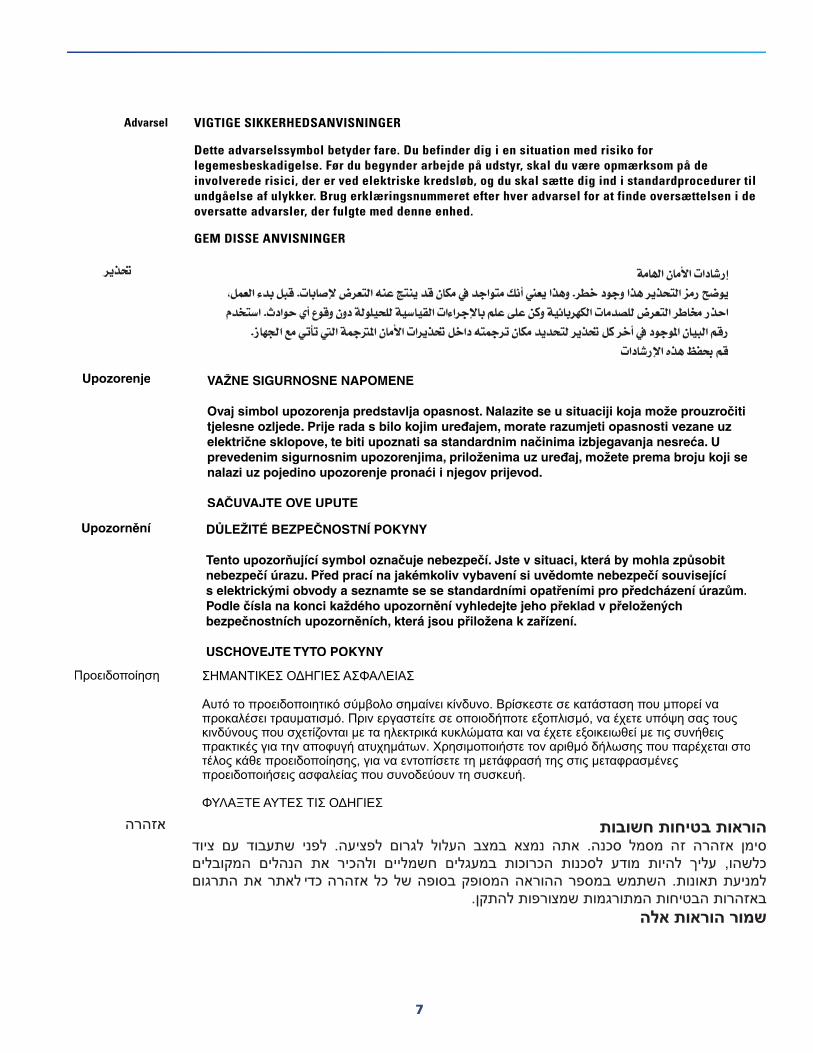
Advarsel VIGTIGE SIKKERHEDSANVISNINGER
Dette advarselssymbol betyder fare. Du befinder dig i en situation med risiko for legemesbeskadigelse. Før du begynder arbejde på udstyr, skal du være opmærksom på de involverede risici, der er ved elektriske kredsløb, og du skal sætte dig ind i standardprocedurer til undgåelse af ulykker. Brug erklæringsnummeret efter hver advarsel for at finde oversættelsen i de oversatte advarsler, der fulgte med denne enhed.
GEM DISSE ANVISNINGER
7

WARNING: When installing the product, please use the provided or designated connection cables/power cables/AC adapters. Using any other cables/adapters could cause a malfunction or a fire. Electrical Appliance and Material Safety Law prohibits the use of UL-certified cables (that have the “UL” shown on the code) for any other electrical devices than products designated by CISCO. The use of cables that are certified by Electrical Appliance and Material Safety Law (that have “PSE” shown on the code) is not limited to CISCO-designated products. Statement 371
WARNING: Read the wall-mounting instructions carefully before beginning installation. Failure to use the correct hardware or to follow the correct procedures could result in a hazardous situation to people and damage to the system. Statement 378
8

WARNING: Read the installation instructions before connecting the system to the power source. Statement 1004
WARNING: To avoid electric shock, do not connect safety extra-low voltage (SELV) circuits to telephone-network voltage (TNV) circuits. LAN ports contain SELV circuits, and WAN ports contain TNV circuits. Some LAN and WAN ports both use RJ-45 connectors. Use caution when connecting cables. Statement 1021
WARNING: This equipment must be grounded. Never defeat the ground conductor or operate the equipment in the absence of a suitably installed ground conductor. Contact the appropriate electrical inspection authority or an electrician if you are uncertain that suitable grounding is available. Statement 1024
WARNING: Connect the unit only to DC power source that complies with the safety extra-low voltage (SELV) requirements in IEC 60950 based safety standards. Statement 1033
WARNING: When installing or replacing the unit, the ground connection must always be made first and disconnected last. Statement 1046
WARNING: Do not locate the antenna near overhead power lines or other electric light or power circuits, or where it can come into contact with such circuits. When installing the antenna, take extreme care not to come into contact with such circuits, because they may cause serious injury or death. For proper installation and grounding of the antenna, please refer to national and local codes (for example, U.S.:NFPA 70, National Electrical Code, Article 810, Canada: Canadian Electrical Code, Section 54). Statement 1052
WARNING: No user-serviceable parts inside. Do not open. Statement 1073
WARNING: Installation of the equipment must comply with local and national electrical codes. Statement 1074
WARNING: Only trained and qualified personnel should be allowed to install, replace, or service this equipment. Statement 1030
WARNING: Ultimate disposal of this product should be handled according to all national laws and regulations. Statement 1040
WARNING: The covers are an integral part of the safety design of the product. Do not operate the unit without the covers installed. Statement 1077
WARNING: Hot surface. Statement 1079
Related Documentation Cisco IOS Release Notes
https://www.cisco.com/c/en/us/support/routers/1100-series-industrial-integrated-services-routers/products-release-notes-list.html
Searching Cisco DocumentsTo search an HTML document using a web browser, press Ctrl-F (Windows) or Cmd-F (Apple). In most browsers, the option to search whole words only, invoke case sensitivity, or search forward and backward is also available.
To search a PDF document in Adobe Reader, use the basic Find toolbar (Ctrl-F) or the Full Reader Search window (Shift-Ctrl-F). Use the Find toolbar to find words or phrases within a specific document. Use the Full Reader Search window to search multiple PDF files simultaneously and to change case sensitivity and other options. Adobe Reader’s online help has more information about how to search PDF documents.
9
Obtaining Documentation and Submitting a Service RequestFor information on obtaining documentation, submitting a service request, and gathering additional information, see the monthly What’s New in Cisco Product Documentation, which also lists all new and revised Cisco technical documentation, at:
http://www.cisco.com/en/US/docs/general/whatsnew/whatsnew.html
Subscribe to the What’s New in Cisco Product Documentation as a Really Simple Syndication (RSS) feed and set content to be delivered directly to your desktop using a reader application. The RSS feeds are a free service and Cisco currently supports RSS Version 2.0.
10

Product OverviewThis chapter provides an overview of the features available for the Cisco IR1101 and contains the following sections:
General Description, page 11
SKU Information, page 16
Hardware Features, page 17
— Platform Features for Cisco IR1101 (Base), page 17
— Platform Features for Cisco IR1101 (Pluggable Module), page 17
Supported Cisco Antennas and Cables, page 18
Power Supply, page 21
RJ45 Ports, page 22
SFP Module, page 22
NOTE: Prior to installing this device read the Regulatory Compliance and Safety Information.
General DescriptionThe Cisco IR1101 Industrial Integrated Services Router is a next generation modular industrial router which has a base module with additional Pluggable Modules that can be added. The Pluggable Module provides the flexibility of adding different interfaces to the IR1101 platform, for example, a cellular module.
11
Cisco Systems, Inc. www.cisco.com

Figure 1 Cisco IR1101 Industrial Integrated Services Router
In addition, the Base module has a connector interface on each side to stack future modules. Figure 2 shows the IR1101 Base Module.
Figure 2 Cisco IR1101 Integrated Services Router with USB covers in place
Figure 3 shows the front panel details of the Cisco IR1101.
1 USB 2.0 Port Cover 2 Mini-USB Console Cover
12

Figure 3 Cisco IR1101 Front Panel
Figures Figure 4 and Figure 5 show an example of a Pluggable Module. In this case, the LTE Pluggable Module.
Figure 4 LTE Pluggable Module (front)
1 SFP GE WAN 6 Grounding Point (on side of device)
2 USB 2.0 7 DC Power and Alarm Input
3 RJ45 GE WAN 8 Mini-USB Console
4 Serial Port 9 Reset Button
5 FE LAN Ports 1-4 10 Pluggable Module
1 LTE-Main SMA 3 Micro USB Debug Port
2 GPS SMA 4 LTE-Div SMA
13

Figure 5 LTE Pluggable Module (with antennas)
Front Panel Icons and LEDsThe IR1101 uses icons to show the different features of the device. Table 1 shows Icons and their associated LEDs with descriptions. Table 2 shows the Icons without associated LEDs and their descriptions.
14

Table 1 Icons with LEDs
Table 2 Icons only
Icon Description/Activity Icon Description/Activity
System - Power and System Status.
Off — No power
Green Steady on — Normal operation
Green Flashing — Boot up phase or in ROM Monitor mode
Amber Steady on — Power is OK but possible internal failure
Alarm - Alarm Input Status
Off — Normal operation
Red - Alarm State on the Alarm Input
VPN
Off — No VPN tunnel
Steady Green — At least one VPN tunnel is up
Red, Green, and Blue User Configurable LED
Gigabit Ethernet Combo Port
Off — No Link
Solid Green — Copper Link up, no activity
Flashing Green — Copper Link up, with activity
Solid Amber — SFP Link up, no activity
Flashing Amber — SFP Link up, with activity
RJ45 Fast Ethernet Ports -Link Status 0:1
Off — No link
Steady Green — Link is up
Flashing — Transmitting and Receiving data
Icon Description Icon Description
USB 2.0 Console Mini-B Connector USB 2.0 Type A Port for Storage and Networking
Grounding point (located on side of device)
Reset Button
15
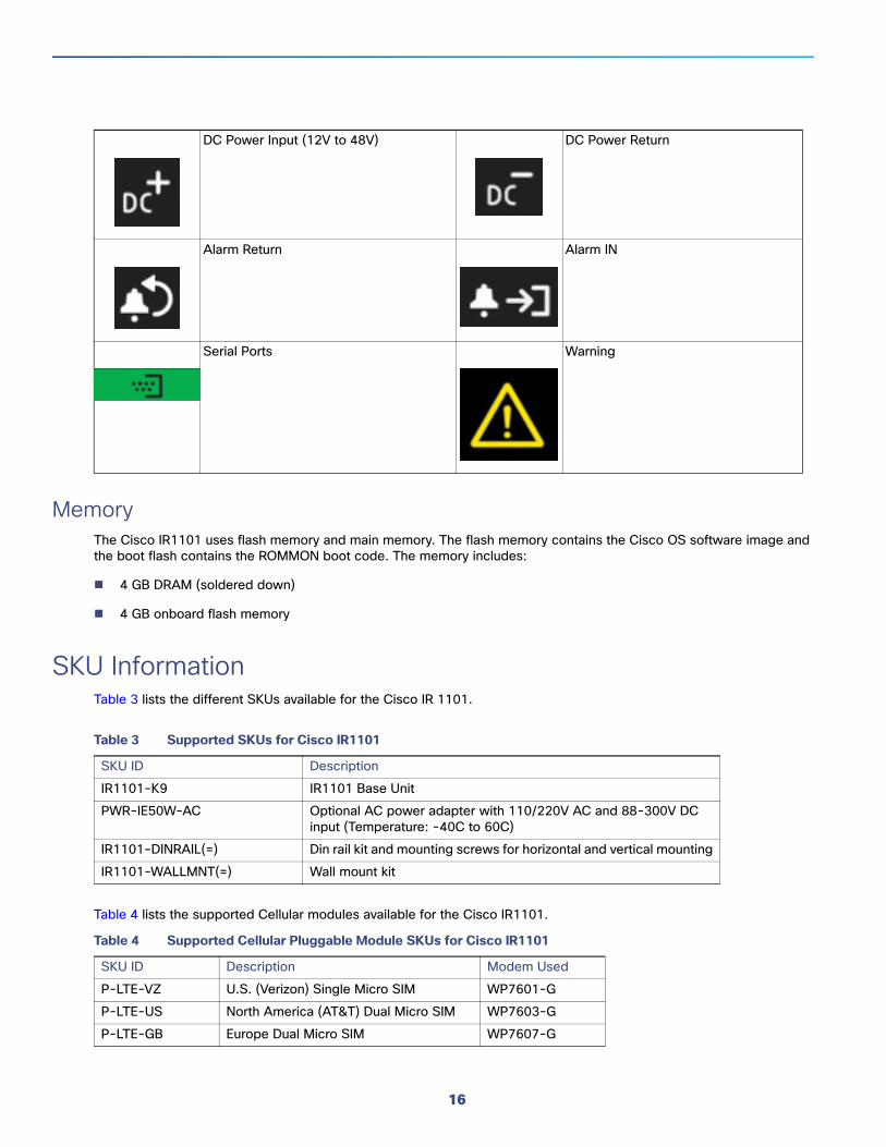
MemoryThe Cisco IR1101 uses flash memory and main memory. The flash memory contains the Cisco OS software image and the boot flash contains the ROMMON boot code. The memory includes:
4 GB DRAM (soldered down)
4 GB onboard flash memory
SKU InformationTable 3 lists the different SKUs available for the Cisco IR 1101.
Table 4 lists the supported Cellular modules available for the Cisco IR1101.
DC Power Input (12V to 48V) DC Power Return
Alarm Return Alarm IN
Serial Ports Warning
Table 3 Supported SKUs for Cisco IR1101
SKU ID Description
IR1101-K9 IR1101 Base Unit
PWR-IE50W-AC Optional AC power adapter with 110/220V AC and 88-300V DC input (Temperature: -40C to 60C)
IR1101-DINRAIL(=) Din rail kit and mounting screws for horizontal and vertical mounting
IR1101-WALLMNT(=) Wall mount kit
Table 4 Supported Cellular Pluggable Module SKUs for Cisco IR1101
SKU ID Description Modem Used
P-LTE-VZ U.S. (Verizon) Single Micro SIM WP7601-G
P-LTE-US North America (AT&T) Dual Micro SIM WP7603-G
P-LTE-GB Europe Dual Micro SIM WP7607-G
16

Hardware FeaturesThis section provides an overview of the following hardware features for the Cisco IR1101.
Platform Features for Cisco IR1101 (Base)The following lists the hardware platform features for the Cisco IR1101.
External Power Entry
— Nominal: 12 to 48VDC
— Absolute min/max: 9.6 to 60VDC
— Typical current: 0.82A to 0.22A
— Maximum current: 0.91A to 0.28A
— 4-pin 3.8 mm EURO power connector
External Reset/Recovery Push Button
Gigabit Ethernet Combo RJ45+SFP connector.
— RJ45 connector will support IEEE802.3 Ethernet over copper wiring standards of 10Base-T, 100Base-TX, and 1000Base-T
— SFP port will support 1000Base-X or 100Base-FX Fiber Ethernet standard SFP (see the supported list of SFP’s here: SFP Module, page 22)
LAN Ports
— 4x RJ45 10/100 Fast Ethernet
Serial Port
— 1 x RJ45 RS232 Port (DTE)
USB Ports
— 1x USB 2.0 Type A Host Port
— 1x USB 2.0 mini USB Type B console port
Compliance
— Class A EMC or better
— IP30 compliant when vertical and ports downward
Industrial temperature [-40ºC to +60ºC, 13.8Kft (operating), 15Kft (non-operating)]
One alarm input
Platform Features for Cisco IR1101 (Pluggable Module)The IR1101 is designed to accept a Pluggable Module. There is additional documentation for the Pluggable Module in the Cisco 1000 Series guides that can be found here:
17

Hardware Installation Guide for the Cisco 1000 Series Integrated Services Router
Cisco 1100 Series Software Configuration Guide
Highlights of the LTE Pluggable Module are:
All Wireless interfaces are supported through a Pluggable Module
Micro-Sim, 3FF size, Industrial Temperature range of -40C to +105C
Reset ButtonThe Reset button resets the router configuration to the default configuration set by the factory. To restore the router configuration to the default configuration set by the factory, use a standard size #1 paper clip with wire gauge 0.033 inch or smaller and simultaneously press the reset button while applying power to the router.
Supported Cisco Antennas and CablesThe IR1101 must have an expansion module with antenna ports installed in order to connect antennas. The base unit does not have any wireless capabilities on its own.
The following section lists the supported Antennas and Cables for the Cisco IR1101 with a wireless Pluggable Module. For detailed information about Cisco Antennas for the Industrial Routers, please refer to the following guide:
Cisco Industrial Routers and Industrial Wireless Access Points Antenna Guide:
http://www.cisco.com/c/en/us/td/docs/routers/connectedgrid/antennas/installing-combined/industrial-routers-and-industrial-wireless-antenna-guide.html
The following antennas and cables are available:
LTE-ANTM-SMA-DOmnidirectional 4G/LTE Swivel Mount Dipole antenna designed for indoor use with Cisco 4G Long Term Evolution (LTE) routers and modules with an SMA(f) connector. Articulating Joint which can be rotated 360 degrees and is capable of maneuvering into three stop positions: 0 degrees, 45 degrees, and 90 degrees. Male sub-miniature A (SMA) Connector which allows direct mounting of the antenna to any Cisco supported router with a female SMA connector. The LTE-ANTM-SMA-D antenna is marked with a dual green band to indicate that it supports Cisco LTEA routers and modules.
This antenna has the following features:
Support for frequencies of 698-960, 1448-1511, and 1710-2690 MHz.
Standalone antenna peak gain of less than 3.7 dBi in the supported frequency bands.
Articulating joint that can maneuver into three stop positions: 0°, 45°, and 90°.
Male SubMiniature A connector that allows direct mounting of the antenna to any Cisco supported router or Pluggable Module with an SMA connector.
The SMA connector design has added rotational frictional torque to ensure the SMA interface stays properly mated, and to reduce chances of a disconnect. The design is also more finger friendly compared to a classic SMA hex nut design.
ANT-4G-PNL-OUT-NCisco Multiband Panel Outdoor 4G MIMO dual port antenna, designed to cover cellular 4G bands.
The supported bands are:
18

LTE700/Cellular/PCS/AWS/MDS
Global GSM900/GSM1800/UMTS/LTE2600
ANT-4G-OMNI-OUT-NThe Cisco Outdoor Omnidirectional Antenna for 2G/3G/4G Cellular antenna is designed to cover domestic LTE700/Cellular/PCS/AWS/MDS, WiMAX 2300/2500, and GSM900/GSM1800/UMTS/LTE2600 bands. The Omnidirectional Outdoor Antenna is compatible with Cisco 2G, 3G, and 4G cellular devices that use a Type N connector and requires a mast-mounted outdoor antenna.
4G-LTE-ANTM-O-3-B4G-LTE-ANTM-O-3 antenna is an integrated 3-in-1- indoor and outdoor antenna. It comes with two Long Term Evolution (LTE) antennas and one Global Positioning System (GPS) antenna in a single radome.
The 4G-LTE-ANTM-O-3 antenna supports the following features:
No tune, multiband coverage, dual 4G LTE, and GPS L1 frequencies.
Metal 5/8-inch stud mount with serrated face nut provides single cable exit for easier installation or antenna replacement.
Attractive low-profile housing for added overhead clearance.
IP67-compliant design provides maximum protection against water or dust under severe environmental conditions.
High-performance, low-loss cable, and high-quality connectors for maximum Radio Frequency (RF) system efficiency.
UV-resistant red, blue, black, or white radome.
ANT-3-4G2G1-OCisco Cellular 3-in-1 Vehicle Mount and Fixed Infrastructure Antenna. The antenna is a three port antenna with two elements designed to cover the 698-960, 1448-1511 and 1710-2700 MHz cellular bands and one GPS element. The antenna can be mounted on the roof of a vehicle or fixed structure. The antenna meets or exceeds a variety of environmental ruggedization specifications for transportation applications.
The antenna features:
Three antenna elements within one radome: two cellular and one GPS
Outdoor and transportation ready
Roof mount installation
Dual cellular elements supporting 698-960, 1448-1511 and 1710-2700 MHz
— Omnidirectional, vertically polarized, MIMO
— Integrated 2 foot cables with TNC male connectors
— LTE elements are interchangeable, either one can be connected to Main or Aux
Active GPS antenna has integrated 17 foot cable with SMA male connector
19

ANT-2-4G2-OCisco Cellular 2-in-1 Vehicle Mount and Fixed Infrastructure Antenna. The antenna is a two port antenna with two elements designed to cover the 698-960, 1448-1511, and 1710-2700 MHz cellular bands. The antenna can be mounted on the roof of a vehicle or fixed structure. The antenna meets or exceeds a variety of environmental ruggedization specifications for transportation applications.
The antenna features:
Two cellular antenna elements within one radome
Outdoor and transportation ready
Roof mount installation
Dual cellular elements supporting 698-960, 1448-1511 and 1710-2700 MHz
— Omnidirectional, vertically polarized, MIMO
— Integrated 2 foot cables with TNC male connectors
LTE elements are interchangeable, either one can be connected to Main or Aux.
GPS-ACT-ANTM-SMACisco 4G indoor/outdoor, active GPS antenna that can be physically connected to the Cisco Integrated Services Routers (ISRs) and Cisco 4G Enhanced High-Speed WAN Interface Cards (EHWICs) to receive GPS broadcasts from satellites.
The antenna features:
Dimensions 1.7 (L) x 1.4 (W) x 0.55 (H) in. (44 x 36 x 14mm)
1574.42 - 1576.42 MHz
17 ft (5.18 meters)
ANT-GPS-OUT-TNCThis Cisco GPS Antenna is designed to cover a domestic frequency of 1575 MHz. This antenna is compatible with any Cisco device that uses GPS, and is compatible with active GPS antennas with DC specifications. Connector adapters may be required from TNC(m) to the required interface. The antenna is a rugged outdoor antenna, and is IP67 rated.
The GPS antenna features the following:
Outdoor ruggedized antenna
Low-profile housing
Integrated LMR-100 cable with right-angle TNC(m) male connector
Modem SupportThe Cisco IR1101 wireless Pluggable Module uses the WP76xx series modems. The software download page can be found here:
https://software.cisco.com/download/navigator.html?mdfid=286288566&flowid=76082
Table 5 and Table 6 shows the technology details for the modems.
20

Table 5 Modem Technology Supported
Table 6 GNSS Technology Supported
Power SupplyThe Cisco IR1101 comes with an external DC power connector. The 4-pin power entry connector (receptacle) is mounted to the unit. The 4-pin power entry mating connector (plug) is attached to the receptacle. It is removed during installation and used to connect to the DC power source, then reattached to provide power to the unit.
Note: The Cisco part number for the connector is 29-6115-01.
Refer to Figure 6 for the location and values of the power connector.
Figure 6 Power Connector Pin-Outs
Modem Used Technology Supported
WP7601-G LTE CAT4: B4, B13
WP7603-G LTE CAT4:B2,B4,B5,B12HSPA+,UMTS: B2,B4,B5
WP7607-G LTE CAT4: B3, B5, B8, B20, B28HSPA+: B1, B5, B8EDGE: 900/1800
Technology RF Band Receive (Rx) Band MHz
GNSS GPS 1575.42 +/- 1.023
GLONASS 1597.52 - 1605.92
Galileo 1575.42 +/- 2.046
BeiDou 1561.098 +/- 2.046
Pin Number Name Description
1 DC In + DC Power Positive Input
2 DC In - DC Power Return
3 ALM REF Alarm Common
4 ALM IN Alarm Input
21
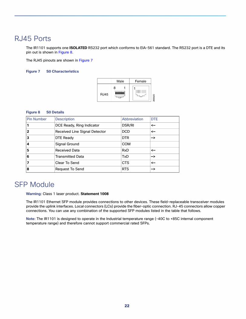
RJ45 PortsThe IR1101 supports one ISOLATED RS232 port which conforms to EIA-561 standard. The RS232 port is a DTE and its pin out is shown in Figure 8.
The RJ45 pinouts are shown in Figure 7
Figure 7 S0 Characteristics
Figure 8 S0 Details
SFP ModuleWarning: Class 1 laser product. Statement 1008
The IR1101 Ethernet SFP module provides connections to other devices. These field-replaceable transceiver modules provide the uplink interfaces. Local connectors (LCs) provide the fiber-optic connection. RJ-45 connectors allow copper connections. You can use any combination of the supported SFP modules listed in the table that follows.
Note: The IR1101 is designed to operate in the Industrial temperature range (-40C to +85C internal component temperature range) and therefore cannot support commercial rated SFPs.
Pin Number Description Abbreviation DTE
1 DCE Ready, Ring Indicator DSR/RI <—
2 Received Line Signal Detector DCD <—
3 DTE Ready DTR —>
4 Signal Ground COM
5 Received Data RxD <—
6 Transmitted Data TxD —>
7 Clear To Send CTS <—
8 Request To Send RTS —>
22
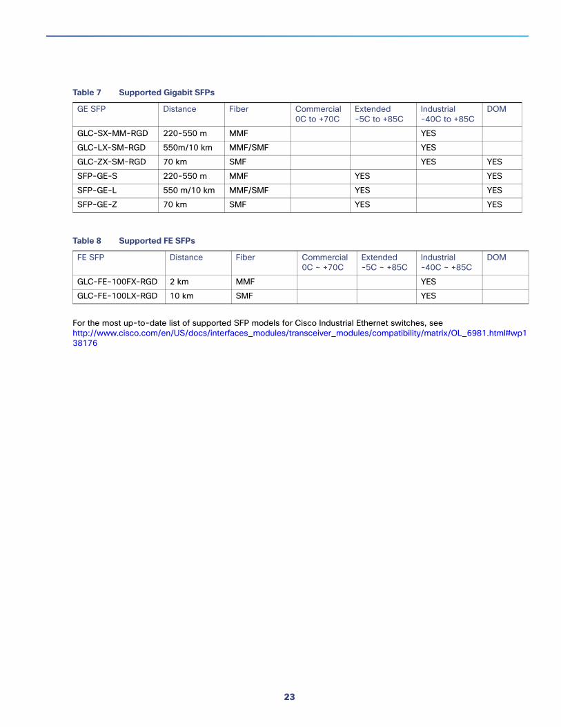
For the most up-to-date list of supported SFP models for Cisco Industrial Ethernet switches, see http://www.cisco.com/en/US/docs/interfaces_modules/transceiver_modules/compatibility/matrix/OL_6981.html#wp138176
Table 7 Supported Gigabit SFPs
GE SFP Distance Fiber Commercial0C to +70C
Extended-5C to +85C
Industrial-40C to +85C
DOM
GLC-SX-MM-RGD 220-550 m MMF YES
GLC-LX-SM-RGD 550m/10 km MMF/SMF YES
GLC-ZX-SM-RGD 70 km SMF YES YES
SFP-GE-S 220-550 m MMF YES YES
SFP-GE-L 550 m/10 km MMF/SMF YES YES
SFP-GE-Z 70 km SMF YES YES
Table 8 Supported FE SFPs
FE SFP Distance Fiber Commercial0C ~ +70C
Extended-5C ~ +85C
Industrial-40C ~ +85C
DOM
GLC-FE-100FX-RGD 2 km MMF YES
GLC-FE-100LX-RGD 10 km SMF YES
23

24

Installing the RouterThis chapter describes the equipment and the procedures for successfully installing the Cisco IR1101 and contains the following sections:
Equipment, Tools, and Connections, page 25
Installing the Router, page 26
Installing Antennas, page 26
Mounting on a Wall, Table, or Other Flat Surface, page 27
Installing a DIN Rail, page 30
Installing the Router Ground Connection, page 33
Pluggable Module, page 34
CAUTION: Do not install the router or power supplies next to a heat source of any kind, including heating vents.
WARNING: Read the installation instructions before connecting the system to the power source. Statement 1004
WARNING: Only trained and qualified personnel should be allowed to install, replace, or service this equipment. Statement 1030
WARNING: Ultimate disposal of this product should be handled according to all national laws and regulations. Statement 1040
WARNING: Do not locate the antenna near overhead power lines or other electric light or power circuits, or where it can come into contact with such circuits. When installing the antenna, take extreme care not to come into contact with such circuits, because they may cause serious injury or death. For proper installation and grounding of the antenna, please refer to national and local codes (for example, U.S.:NFPA 70, National Electrical Code, Article 810, Canada: Canadian Electrical Code, Section 54). Statement 1052
WARNING: No user-serviceable parts inside. Do not open. Statement 1073
WARNING: This product is not intended to be directly connected to the Cable Distribution System. Additional regulatory compliance and legal requirements may apply for direct connection to the Cable Distribution System. This product may connect to the Cable Distribution System ONLY through a device that is approved for direct connection. Statement 1078
WARNING: A minimum of 1 inch clearance is required on all sides of the product when mounting in either horizontal or vertical orientation. Stacking heat-dissipating objects on top of the router is not allowed. I/O side clearance is needed as it is required to access the cable connections. Clearance is required to attach, mount the DIN rail bracket, and Wall mount bracket.
Equipment, Tools, and ConnectionsThis section describes the equipment, tools, and connections necessary for installing your Cisco IR1101.
Note: No antenna is shipped with the IR1101 by default.
25
Cisco Systems, Inc. www.cisco.com

Items Shipped with your RouterUnpack the box and verify that all items listed on the invoice were shipped with the Cisco IR1101.
The following items are shipped with your router:
Getting Started/Product Document of Compliance
Grounding Lug Kit
Power Connector
Additional ItemsThe following items are not shipped with the router but are required for installation:
ESD-preventive cord and wrist strap.
Wire crimper for chassis grounding.
Wire for connecting the chassis to an earth ground.
Ethernet cables for connecting to the Fast Ethernet (FE) WAN and LAN ports.
Ratcheting torque flathead screwdriver that exerts up to 15 in-lb (1.69 N-m) of pressure.
A number-2 Phillips screwdriver.
Ethernet DevicesIdentify the Ethernet devices that you will connect to the router: hub, servers, and workstations or PCs. Ensure that each device has a network interface card (NIC) for connecting to Ethernet ports.
Installing the RouterThis section describes how to install the Cisco IR1101. This router can be installed in the following ways:
Table top
Flat horizontal surface
Mounted on a wall
Using a DIN rail
WarningsWARNING: For NEC-compliant grounding, use size 16awg (1.5mm2) or larger copper wire and a ring terminal with an inner diameter of 1/4 in. (6 to 7mm).
Installing AntennasNOTE: Before you install the Cisco IR1101 Integrated Services Router on a table, wall, or DIN rail, install the antennas on the Pluggable Module. It is difficult to install the antennas after the router is installed.
26

There are three SMA connectors on the Pluggable Module. Two connectors are used to connect to the 4G modem. The third connector is used for GPS.
Orient the antennas. For optimum wireless performance, the antennas should be in the vertical orientation with the swivel joint at a 90 degree angle.
If the router is being mounted on a desk, orient the antennas straight up.
To attach the radio antennas to your wireless router, follow these steps:
1. Manually screw the antenna tight to the connectors on the front of the router Pluggable Module.
2. Orient the antennas. For optimum wireless performance, antennas should be generally perpendicular to each other.
Mounting on a Wall, Table, or Other Flat SurfaceThe Cisco IR1101 can be mounted in a vertical or horizontal orientation. It can be mounted to a wall or other flat surface, and can also be mounted to a DIN rail.
TIP: When choosing a location for wall-mounting the router, consider cable limitations and wall structure.
WARNING: Read the wall-mounting instructions carefully before beginning installation. Failure to use the correct hardware or to follow the correct procedures could result in a hazardous situation to people and damage to the system. Statement 378
WARNING: A minimum of 1 inch clearance is required on all sides of the product when mounting to allow for proper air flow.
The wall mounting kit contains the following:
Mounting brackets (x2)
Mounting screws (x4)
To mount the router on a wall or other flat surface, follow these steps:
1. Attach the mounting brackets to the bottom of the router. Refer to Figure 1 for guidance.
27

Figure 1 Cisco IR1101 Mounting Bracket
2. Align the mounting brackets (1) over the mounting holes (3) so that the larger holes on the brackets extend out over the router.
3. Attach the brackets to the router with the 4 screws (2) provided using a Phillips head driver. Torque to 13-15 in. lbs.
4. Mount the router with the attached brackets in a proper wall structure to carry the weight of the device. See Figure 2 and Figure 3 for the dimensions of the mounting holes with the brackets attached to the router.
28

Figure 2 Wall/Floor mounting hole dimensions with mounting brackets attached
Note: Four #10-32 screws are recommended when mounting the unit with these brackets attached to the neighboring surface.
29

Figure 3 Wall/Floor mounting clearance and overall dimensions with mounting brackets attached
5. Route the cables so that they do not put a strain on the connectors or mounting hardware.
Installing a DIN RailThe DIN Rail kit is ordered separately.
The DIN Rail can be installed in two different orientations, horizontally and vertically.
To attach the DIN rail bracket to the Cisco IR1101, follow these steps.
Mounting the DIN Rail Bracket on the Router1. First, attach the DIN rail bracket to the back of the router. The DIN rail bracket mounts in two different ways,
depending on the orientation you wish to use. See Figure 4 for vertical orientation, and Figure 5 for horizontal orientation.
30

Figure 4 Attaching the DIN Rail Bracket for vertical mounting
Note: Position the router with the ground lug facing down for vertical mounting.
Figure 5 Attaching the DIN Rail Bracket for horizontal mounting
Note: Position the router with the front ports facing down for horizontal mounting.
31
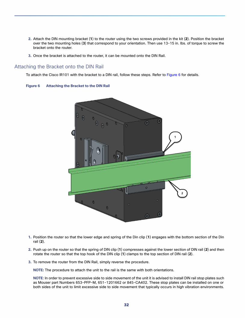
2. Attach the DIN mounting bracket (1) to the router using the two screws provided in the kit (2). Position the bracket over the two mounting holes (3) that correspond to your orientation. Then use 13-15 in. lbs. of torque to screw the bracket onto the router.
3. Once the bracket is attached to the router, it can be mounted onto the DIN Rail.
Attaching the Bracket onto the DIN Rail To attach the Cisco IR101 with the bracket to a DIN rail, follow these steps. Refer to Figure 6 for details.
Figure 6 Attaching the Bracket to the DIN Rail
1. Position the router so that the lower edge and spring of the Din clip (1) engages with the bottom section of the Din rail (2).
2. Push up on the router so that the spring of DIN clip (1) compresses against the lower section of DIN rail (2) and then rotate the router so that the top hook of the DIN clip (1) clamps to the top section of DIN rail (2).
3. To remove the router from the DIN Rail, simply reverse the procedure.
NOTE: The procedure to attach the unit to the rail is the same with both orientations.
NOTE: In order to prevent excessive side to side movement of the unit it is advised to install DIN rail stop plates such as Mouser part Numbers 653-PFP-M, 651-1201662 or 845-CA402. These stop plates can be installed on one or both sides of the unit to limit excessive side to side movement that typically occurs in high vibration environments.
32
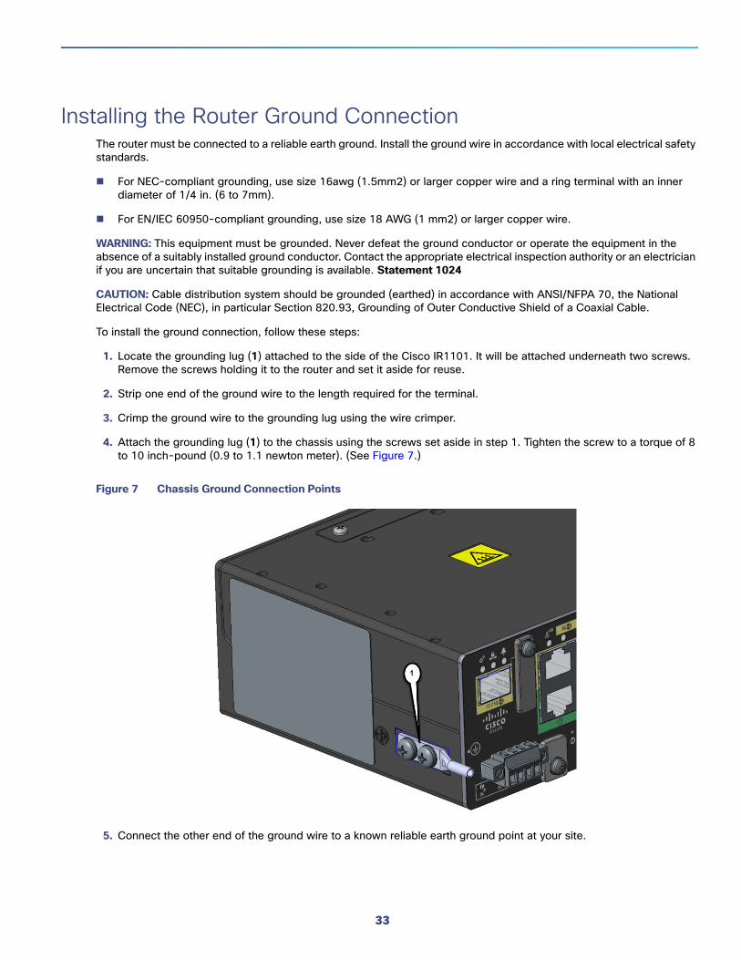
Installing the Router Ground ConnectionThe router must be connected to a reliable earth ground. Install the ground wire in accordance with local electrical safety standards.
For NEC-compliant grounding, use size 16awg (1.5mm2) or larger copper wire and a ring terminal with an inner diameter of 1/4 in. (6 to 7mm).
For EN/IEC 60950-compliant grounding, use size 18 AWG (1 mm2) or larger copper wire.
WARNING: This equipment must be grounded. Never defeat the ground conductor or operate the equipment in the absence of a suitably installed ground conductor. Contact the appropriate electrical inspection authority or an electrician if you are uncertain that suitable grounding is available. Statement 1024
CAUTION: Cable distribution system should be grounded (earthed) in accordance with ANSI/NFPA 70, the National Electrical Code (NEC), in particular Section 820.93, Grounding of Outer Conductive Shield of a Coaxial Cable.
To install the ground connection, follow these steps:
1. Locate the grounding lug (1) attached to the side of the Cisco IR1101. It will be attached underneath two screws. Remove the screws holding it to the router and set it aside for reuse.
2. Strip one end of the ground wire to the length required for the terminal.
3. Crimp the ground wire to the grounding lug using the wire crimper.
4. Attach the grounding lug (1) to the chassis using the screws set aside in step 1. Tighten the screw to a torque of 8 to 10 inch-pound (0.9 to 1.1 newton meter). (See Figure 7.)
Figure 7 Chassis Ground Connection Points
5. Connect the other end of the ground wire to a known reliable earth ground point at your site.
33

6. If you are using this router in a vehicle, attach the ring terminal to the chassis using one of the screws provided and the green or green and yellow striped wire. Connect the other end of the wire to the vehicle ground.
After you install and properly ground the router, you can connect the power wiring, the LAN cables, and the cables for administrative access as required for your installation.
Pluggable ModuleThe Pluggable Module provides the IR1101 with a number of different configuration options. In this section the modular cellular modem Pluggable Module remove and replace option is shown.
The IR1101 may have a blank plate covering the Pluggable Module slot. This will need to be removed prior to installing the cellular modem module. The following example shows the LTE Pluggable Module.
1. Remove the blank plate by unscrewing the latch lock screw(1) that holds the plate secure. See Figure 8.
Figure 8 Latch Lock Screw
2. Slide the blank plate out of the device.
3. Prepare the cellular modem module by inserting the micro sims applicable for your modems into the device. Remove the screw (1) holding the access plate in place that covers the sim slots. It is located on the side of the module, as shown in Figure 9
Figure 9 Sim Access Plate
4. Install your sims as shown in Figure 10. Make note of the proper slot number and sim orientation.
34

Figure 10 Sim Installation
5. Push in each SIM until it clicks into place. When the SIMs are installed, re-attach the access plate previously removed with a screwdriver. Torque to 2.8 to 3.8 inch-lbs (0.9-1.1 newton meter).
6. If your Pluggable Module is the type that has a USB port, make sure that the USB cover is properly installed. Place the USB cover (1) with the plug indentation against the USB port (2). The half circle of the USB cover fits behind the latch lock screw. See Figure 11 for details.
Item Description
1 Micro SIMs
2 SIM 0 (towards the device)
3 SIM 1 (away from device)
35
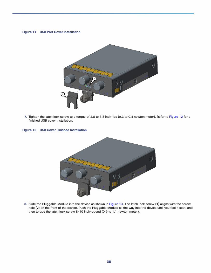
Figure 11 USB Port Cover Installation
7. Tighten the latch lock screw to a torque of 2.8 to 3.8 inch-lbs (0.3 to 0.4 newton meter). Refer to Figure 12 for a finished USB cover installation.
Figure 12 USB Cover Finished Installation
8. Slide the Pluggable Module into the device as shown in Figure 13. The latch lock screw (1) aligns with the screw hole (2) on the front of the device. Push the Pluggable Module all the way into the device until you feel it seat, and then torque the latch lock screw 8-10 inch-pound (0.9 to 1.1 newton meter).
36
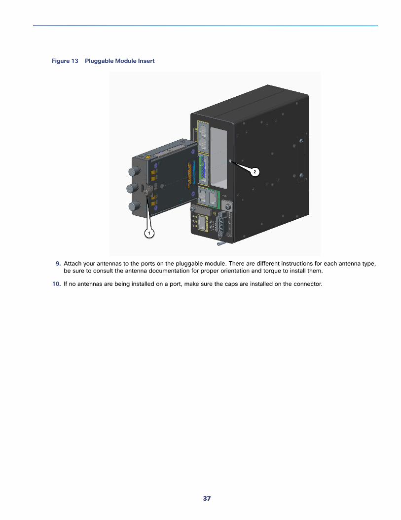
Figure 13 Pluggable Module Insert
9. Attach your antennas to the ports on the pluggable module. There are different instructions for each antenna type, be sure to consult the antenna documentation for proper orientation and torque to install them.
10. If no antennas are being installed on a port, make sure the caps are installed on the connector.
37

38

Connecting the RouterThis chapter describes how to connect the IR1101 to Ethernet devices and a network. The chapter contains the following sections:
Preparing to Connect the Router, page 39
Connecting a PC to the Console Port, page 39
Connecting to DC Power, page 40
Verifying Connections, page 43
Preparing to Connect the RouterBefore you connect the router to the devices, install the router according to the instructions in Chapter 4, “Installing the Router”.
Preventing Damage to the RouterTo prevent damage to your router, turn off power to the devices and to the router until all connections are completed.
CAUTION: Do not turn on the devices until after you have completed all connections to the router.
Connecting a PC, Server, or WorkstationTo connect a PC (or other Ethernet devices) to an Ethernet switch port, follow these steps:
1. Connect one end of the Ethernet cable to an Ethernet switch port on the router.
2. Connect the other end of the cable to the RJ-45 port on the network interface card (NIC) that is installed in the PC, server, or workstation.
3. (Optional) Connect additional servers, PCs, or workstations to the other Ethernet switch ports.
Connecting a PC to the Console PortConnect a PC to the Console port either to configure the software by using the CLI or to troubleshoot problems with the router.
To connect a terminal or PC to the console port on the router and access the CLI, follow these steps:
1. Connect the mini-USB console cable to the console port on the router. Figure 1 shows the console location on the router.
39
Cisco Systems, Inc. www.cisco.com

Figure 1 Connecting a Terminal or PC to the Console Port2. Connect the opposite end of the mini-USB cable to the USB port on your laptop or PC.
3. To communicate with the router, wait for your laptop or PC to discover the new device.
4. If your laptop or PC warns you that you do not have the proper drivers to communicate with the router, you can obtain them from your computers manufacturer, or go here:https://www.silabs.com/products/mcu/Pages/USBtoUARTBridgeVCPDrivers.aspx
Connecting to DC PowerWarning: This product relies on the building’s installation for short-circuit (overcurrent) protection. Ensure that the protective device is rated not greater than 60 VDC minimum, 5A maximum. Statement 1005
WARNING: Connect the unit only to DC power source that complies with the safety extra-low voltage (SELV) requirements in IEC 60950 based safety standards. Statement 1033
WARNING: This product requires short-circuit (overcurrent) protection, to be provided as part of the building installation. Install only in accordance with national and local wiring regulations. Statement 1045
Plugs and Pin-OutsThe IR1101 ships with a DC power accessory kit.
The power entry receptacle is on the IR1101. The pin-outs are shown in Figure 2.
40

Figure 2 Power Connector Pin-outs
Table 1 Power connector Descriptions
Wiring the DC PowerTo connect the DC power on your Cisco IR1101, follow these steps:
Pin Number Name Description
1 DC In + DC Power Positive Input
2 DC In - DC Power Return (GND-)
3 AC Alarm Common
4 AI Alarm Input
41

1. Locate the power and alarm connector on the router front panel.
NOTE: Your connector may not have the labels V RT A A.
In the labeled connector, the pins are:
V—Positive DC power connection
RT— Return DC power connection
A— Alarm Common
A— Alarm Input
2. Identify the connector positive and return DC power connections. The connections left to right are:
1—Positive DC power connection
2—Return DC power connection
3—Alarm Common
4—Alarm Input
3. Measure two strands of twisted-pair copper wire (18-to-20 AWG) long enough to connect to the DC power source.
4. Using an 18-gauge wire-stripping tool, strip each of the two twisted pair wires coming from each DC-input power source to 0.25 inch (6.3 mm) ± 0.02 inch (0.5 mm). Do not strip more than 0.27 inch (6.8 mm) of insulation from the wire. Stripping more than the recommended amount of wire can leave exposed wire from the power connector after installation.
5. Remove the two captive screws that attach the power and alarm connector to the router, and remove the connector.
6. On the power and alarm connector, insert the exposed part of the positive wire into the connection labeled "V" and the exposed part of the return wire into the connection labeled "RT". Make sure that you cannot see any wire lead. Only wire with insulation should extend from the connector.
NOTE: Use the same method for wiring the alarm connections.
1—Power connector captive screws
7. Use a ratcheting torque flathead screwdriver to torque the power connector captive screws (above the installed wire leads) to 2 in-lb (0.23 N-m).
8. Connect the other end of the positive wire to the positive terminal on the DC power source, and connect the other end of the return wire to the return terminal on the DC power source.Connect the other end of the Alarm wires to your alarm source.
3919
20
3330
8439
1942
1
42

Verifying ConnectionsTo verify that all devices are properly connected to the router, first turn on all the connected devices, then check the LEDs. To verify router operation, refer to the Front Panel Icons and LEDs, page 14.
43

44
Technical SpecificationsThis appendix provides router, port, cabling specifications, and power adapters for the IR1101.
Complete specifications for the IR1101 can be found in the marketing data sheet.
NOTE: Complete Regulatory Compliance and Safety Information is found online.
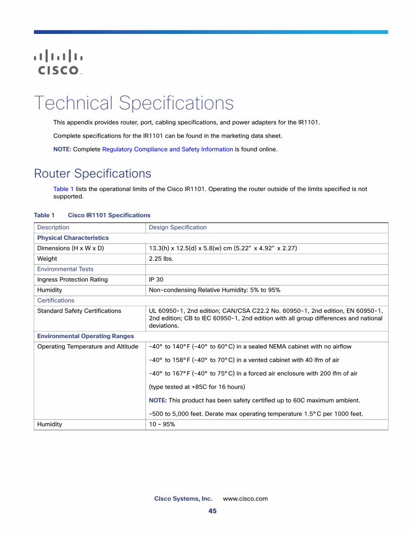
Router SpecificationsTable 1 lists the operational limits of the Cisco IR1101. Operating the router outside of the limits specified is not supported.
Table 1 Cisco IR1101 Specifications
Description Design Specification
Physical Characteristics
Dimensions (H x W x D) 13.3(h) x 12.5(d) x 5.8(w) cm (5.22" x 4.92" x 2.27)
Weight 2.25 lbs.
Environmental Tests
Ingress Protection Rating IP 30
Humidity Non-condensing Relative Humidity: 5% to 95%
Certifications
Standard Safety Certifications UL 60950-1, 2nd edition; CAN/CSA C22.2 No. 60950-1, 2nd edition, EN 60950-1, 2nd edition; CB to IEC 60950-1, 2nd edition with all group differences and national deviations.
Environmental Operating Ranges
Operating Temperature and Altitude -40° to 140°F (-40° to 60°C) in a sealed NEMA cabinet with no airflow
-40° to 158°F (-40° to 70°C) in a vented cabinet with 40 lfm of air
-40° to 167°F (-40° to 75°C) in a forced air enclosure with 200 lfm of air
(type tested at +85C for 16 hours)
NOTE: This product has been safety certified up to 60C maximum ambient.
-500 to 5,000 feet. Derate max operating temperature 1.5°C per 1000 feet.
Humidity 10 – 95%
45
Cisco Systems, Inc. www.cisco.com

Router DC Power Adapter
Input Voltage Nominal voltage: 12V to 48V DC
Min/Max voltage: 9.6V to 60V DC input
Typical Currant 12V - 0.72A24V - 0.36A59.8V - 0.17A
Typical/Maximum Power Consumption
10/13 Watts
Table 1 Cisco IR1101 Specifications
Description Design Specification
46