Embed Size (px)
Citation preview
Router Hardware DescriptionThis section describes the major hardware features of the Cisco 1240 Connected Grid Router (CGR 1240 or router), including the chassis, internal and external connectors and ports, and hardware specifications.
These topics are discussed:
Router Overview, page 13
Hardware Features Detailed Description, page 24
Router Overview Router Applications Overview, page 13
Router Hardware Overview, page 14
Hardware Compliance, page 23
Router Applications OverviewThe CGR 1240 is a ruggedized communication platform, designed for use in Field Area Network (FAN) power distribution grids that require outdoor, pole-mounted routers. The FAN is a distribution system in which power generation and transmission are linked to the power consumers.
The router provides an end-to-end communication network that enables increased power grid efficiency and reliability, reduced energy consumption, and reduced greenhouse gas emissions. The router can be leveraged across applications including:
Advanced Metering Infrastructure (AMI)
Distribution Automation (DA)
Integration of Distributed Energy Resources (DER)
Remote Workforce Automation
Public Lighting
The router provides reliable and secure real-time communication between the FAN systems and the numerous devices that exist on the FAN, including meters, sensors, protection relays, Intelligent Electronic Devices (IEDs), plug-in electric vehicle (PEV) charging stations, and distributed solar farms. Network data is forwarded and processed over secure communication links between devices within the distribution grid for local decision processing.
Additionally, this data is sent to Supervisory Control and Data Acquisition (SCADA) and other management systems. The router supports physical connection to legacy Data Acquisition devices (over the serial port); the data from these devices can also be sent to central SCADA systems using protocol translation over the IP network.
13
Cisco Systems, Inc. www.cisco.com
Router Hardware OverviewTable 2 on page 14 describes the hardware features of the router.
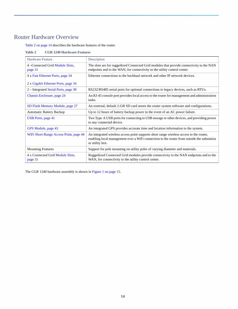
The CGR 1240 hardware assembly is shown in Figure 1 on page 15.
Table 2 CGR 1240 Hardware Features
Hardware Feature Description
4 –Connected Grid Module Slots, page 31
The slots are for ruggedized Connected Grid modules that provide connectivity to the NAN endpoints and to the WAN, for connectivity to the utility control center.
4 x Fast Ethernet Ports, page 34
2 x Gigabit Ethernet Ports, page 34
Ethernet connections to the backhaul network and other IP network devices.
2 – Integrated Serial Ports, page 38 RS232/RS485 serial ports for optional connections to legacy devices, such as RTUs.
Chassis Enclosure, page 24 An RJ-45 console port provides local access to the router for management and administration tasks.
SD Flash Memory Module, page 27 An external, default 2-GB SD card stores the router system software and configurations.
Automatic Battery Backup Up to 12 hours of battery backup power in the event of an AC power failure.
USB Ports, page 41 Two Type A USB ports for connecting to USB storage or other devices, and providing power to any connected device.
GPS Module, page 43 An integrated GPS provides accurate time and location information to the system.
WiFi Short-Range Access Point, page 44 An integrated wireless access point supports short range wireless access to the router, enabling local management over a WiFi connection to the router from outside the substation or utility box.
Mounting Features Support for pole mounting on utility poles of varying diameter and materials.
4 x Connected Grid Module Slots, page 31
Ruggedized Connected Grid modules provide connectivity to the NAN endpoints and to the WAN, for connectivity to the utility control center.
14
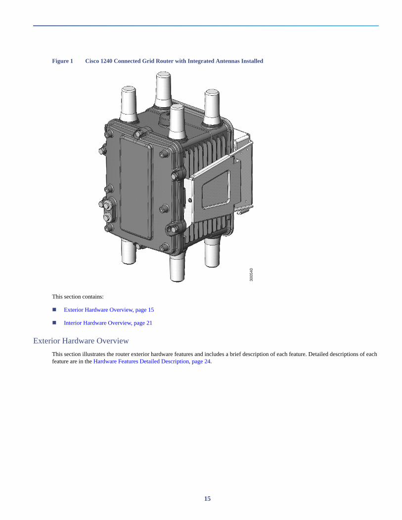
Figure 1 Cisco 1240 Connected Grid Router with Integrated Antennas Installed
This section contains:
Exterior Hardware Overview, page 15
Interior Hardware Overview, page 21
Exterior Hardware Overview
This section illustrates the router exterior hardware features and includes a brief description of each feature. Detailed descriptions of each feature are in the Hardware Features Detailed Description, page 24.
3005
40
15
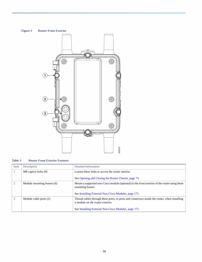
Figure 2 Router Front Exterior
3005
33
1
2
3
Table 3 Router Front Exterior Features
Item Description Detailed Information
1 M8 captive bolts (8) Loosen these bolts to access the router interior.
See Opening and Closing the Router Chassis, page 73.
2 Module mounting bosses (6) Mount a supported non-Cisco module (optional) to the front exterior of the router using these mounting bosses.
See Installing External Non-Cisco Modules, page 171.
3 Module cable ports (2) Thread cables through these ports, to ports and connectors inside the router, when installing a module on the router exterior.
See Installing External Non-Cisco Modules, page 171.
16
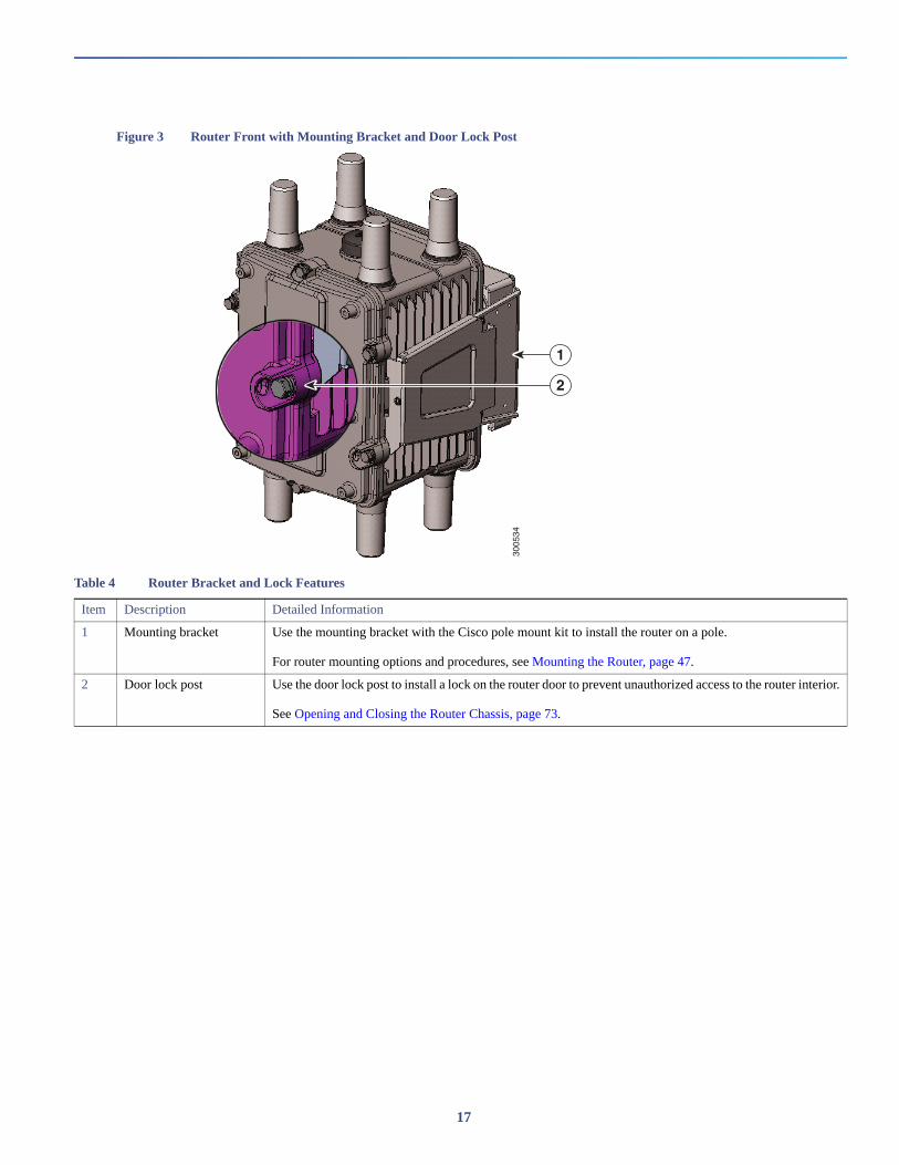
Figure 3 Router Front with Mounting Bracket and Door Lock Post
3005
34
1
2
Table 4 Router Bracket and Lock Features
Item Description Detailed Information
1 Mounting bracket Use the mounting bracket with the Cisco pole mount kit to install the router on a pole.
For router mounting options and procedures, see Mounting the Router, page 47.
2 Door lock post Use the door lock post to install a lock on the router door to prevent unauthorized access to the router interior.
See Opening and Closing the Router Chassis, page 73.
17
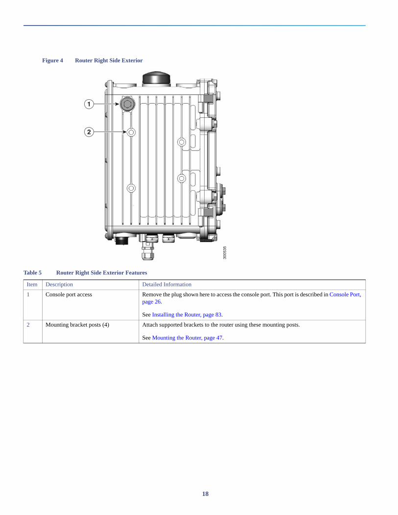
Figure 4 Router Right Side Exterior
3005
35
1
2
Table 5 Router Right Side Exterior Features
Item Description Detailed Information
1 Console port access Remove the plug shown here to access the console port. This port is described in Console Port, page 26.
See Installing the Router, page 83.
2 Mounting bracket posts (4) Attach supported brackets to the router using these mounting posts.
See Mounting the Router, page 47.
18
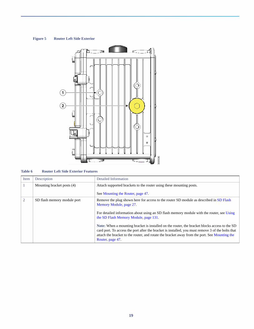
Figure 5 Router Left Side Exterior
3005
36
1
2
Table 6 Router Left Side Exterior Features
Item Description Detailed Information
1 Mounting bracket posts (4) Attach supported brackets to the router using these mounting posts.
See Mounting the Router, page 47.
2 SD flash memory module port Remove the plug shown here for access to the router SD module as described in SD Flash Memory Module, page 27.
For detailed information about using an SD flash memory module with the router, see Using the SD Flash Memory Module, page 131.
Note: When a mounting bracket is installed on the router, the bracket blocks access to the SD card port. To access the port after the bracket is installed, you must remove 3 of the bolts that attach the bracket to the router, and rotate the bracket away from the port. See Mounting the Router, page 47.
19
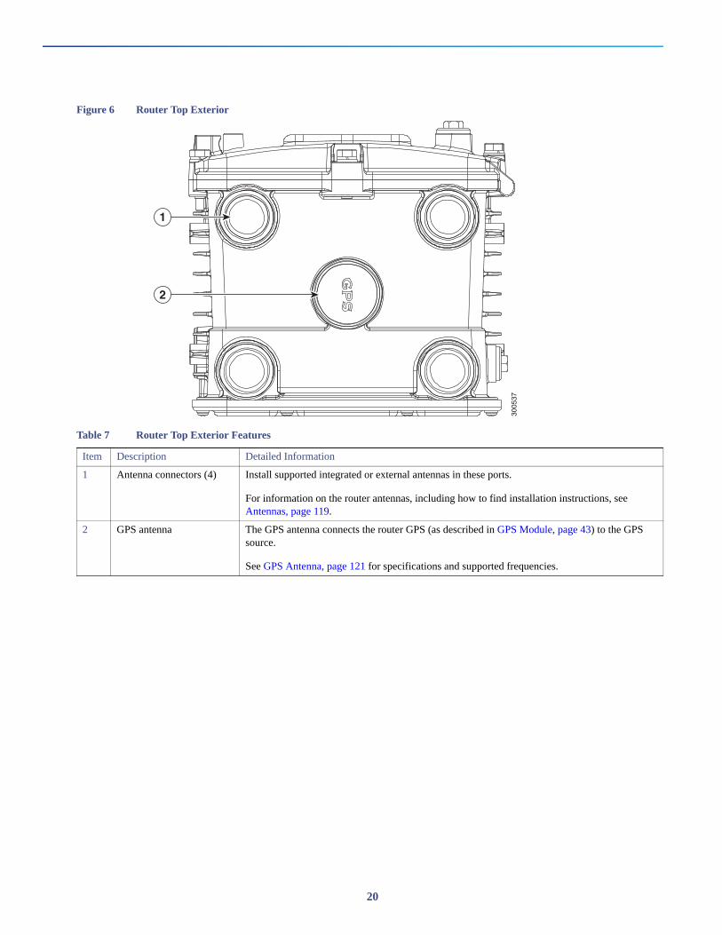
Figure 6 Router Top Exterior
Table 7 Router Top Exterior Features
Item Description Detailed Information
1 Antenna connectors (4) Install supported integrated or external antennas in these ports.
For information on the router antennas, including how to find installation instructions, see Antennas, page 119.
2 GPS antenna The GPS antenna connects the router GPS (as described in GPS Module, page 43) to the GPS source.
See GPS Antenna, page 121 for specifications and supported frequencies.
3005
37
1
2
20
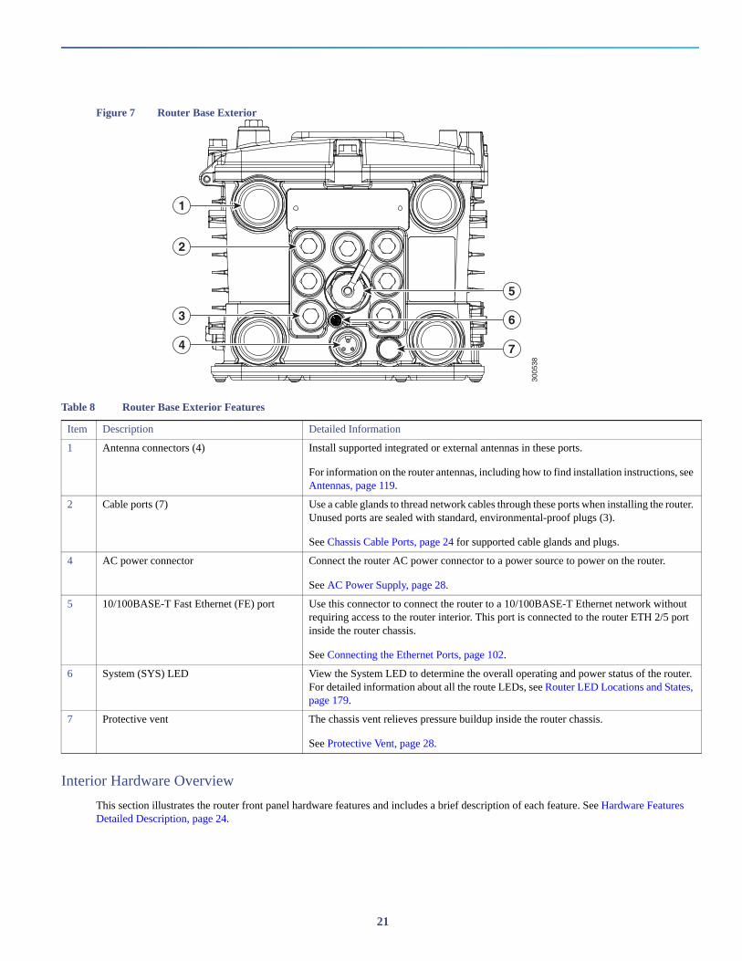
Figure 7 Router Base Exterior
Interior Hardware Overview
This section illustrates the router front panel hardware features and includes a brief description of each feature. See Hardware Features Detailed Description, page 24.
3005
38
1
5
6
7
2
3
4
Table 8 Router Base Exterior Features
Item Description Detailed Information
1 Antenna connectors (4) Install supported integrated or external antennas in these ports.
For information on the router antennas, including how to find installation instructions, see Antennas, page 119.
2 Cable ports (7) Use a cable glands to thread network cables through these ports when installing the router. Unused ports are sealed with standard, environmental-proof plugs (3).
See Chassis Cable Ports, page 24 for supported cable glands and plugs.
4 AC power connector Connect the router AC power connector to a power source to power on the router.
See AC Power Supply, page 28.
5 10/100BASE-T Fast Ethernet (FE) port Use this connector to connect the router to a 10/100BASE-T Ethernet network without requiring access to the router interior. This port is connected to the router ETH 2/5 port inside the router chassis.
See Connecting the Ethernet Ports, page 102.
6 System (SYS) LED View the System LED to determine the overall operating and power status of the router. For detailed information about all the route LEDs, see Router LED Locations and States, page 179.
7 Protective vent The chassis vent relieves pressure buildup inside the router chassis.
See Protective Vent, page 28.
21
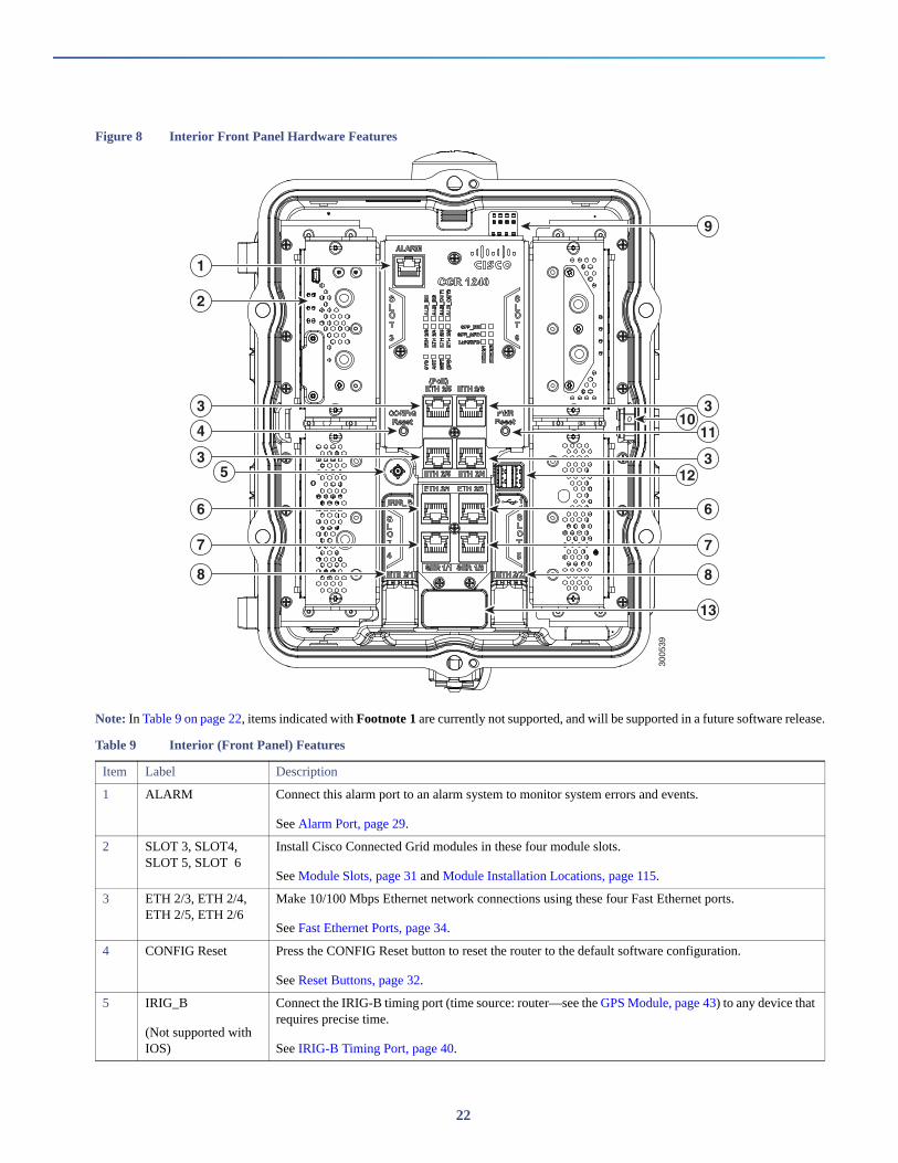
Figure 8 Interior Front Panel Hardware Features
Note: In Table 9 on page 22, items indicated with Footnote 1 are currently not supported, and will be supported in a future software release.
Table 9 Interior (Front Panel) Features
Item Label Description
1 ALARM Connect this alarm port to an alarm system to monitor system errors and events.
See Alarm Port, page 29.
2 SLOT 3, SLOT4, SLOT 5, SLOT 6
Install Cisco Connected Grid modules in these four module slots.
See Module Slots, page 31 and Module Installation Locations, page 115.
3 ETH 2/3, ETH 2/4, ETH 2/5, ETH 2/6
Make 10/100 Mbps Ethernet network connections using these four Fast Ethernet ports.
See Fast Ethernet Ports, page 34.
4 CONFIG Reset Press the CONFIG Reset button to reset the router to the default software configuration.
See Reset Buttons, page 32.
5 IRIG_B
(Not supported with IOS)
Connect the IRIG-B timing port (time source: router—see the GPS Module, page 43) to any device that requires precise time.
See IRIG-B Timing Port, page 40.
3005
39
1
2
3 3
6
7
8
13
3
1110
12
9
6
7
35
4
8
22
Hardware ComplianceFor a complete list of regulatory and compliance standards supported by the Cisco CGR 1240 Router, see the Regulatory Compliance and Safety Information for the Cisco 1000 Series Routers at:http://www.cisco.com/en/US/docs/routers/connectedgrid/cgr1000/rcsi/cgr1000.rsci.html
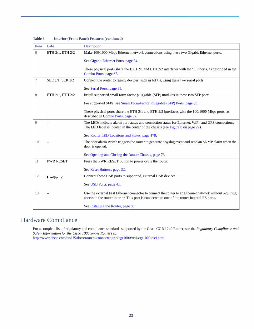
6 ETH 2/1, ETH 2/2 Make 100/1000 Mbps Ethernet network connections using these two Gigabit Ethernet ports.
See Gigabit Ethernet Ports, page 34.
These physical ports share the ETH 2/1 and ETH 2/2 interfaces with the SFP ports, as described in the Combo Ports, page 37.
7 SER 1/1, SER 1/2 Connect the router to legacy devices, such as RTUs, using these two serial ports.
See Serial Ports, page 38.
8 ETH 2/1, ETH 2/2 Install supported small form factor pluggable (SFP) modules in these two SFP ports.
For supported SFPs, see Small Form-Factor Pluggable (SFP) Ports, page 35.
These physical ports share the ETH 2/1 and ETH 2/2 interfaces with the 100/1000 Mbps ports, as described in Combo Ports, page 37.
9 – The LEDs indicate alarm port status and connection status for Ethernet, WiFi, and GPS connections. The LED label is located in the center of the chassis (see Figure 8 on page 22).
See Router LED Locations and States, page 179.
10 – The door alarm switch triggers the router to generate a syslog event and send an SNMP alarm when the door is opened.
See Opening and Closing the Router Chassis, page 73.
11 PWR RESET Press the PWR RESET button to power cycle the router.
See Reset Buttons, page 32.
12
Connect these USB ports to supported, external USB devices.
See USB Ports, page 41.
13 – Use the external Fast Ethernet connector to connect the router to an Ethernet network without requiring access to the router interior. This port is connected to one of the router internal FE ports.
See Installing the Router, page 83.
Table 9 Interior (Front Panel) Features (continued)
Item Label Description
1 2
23
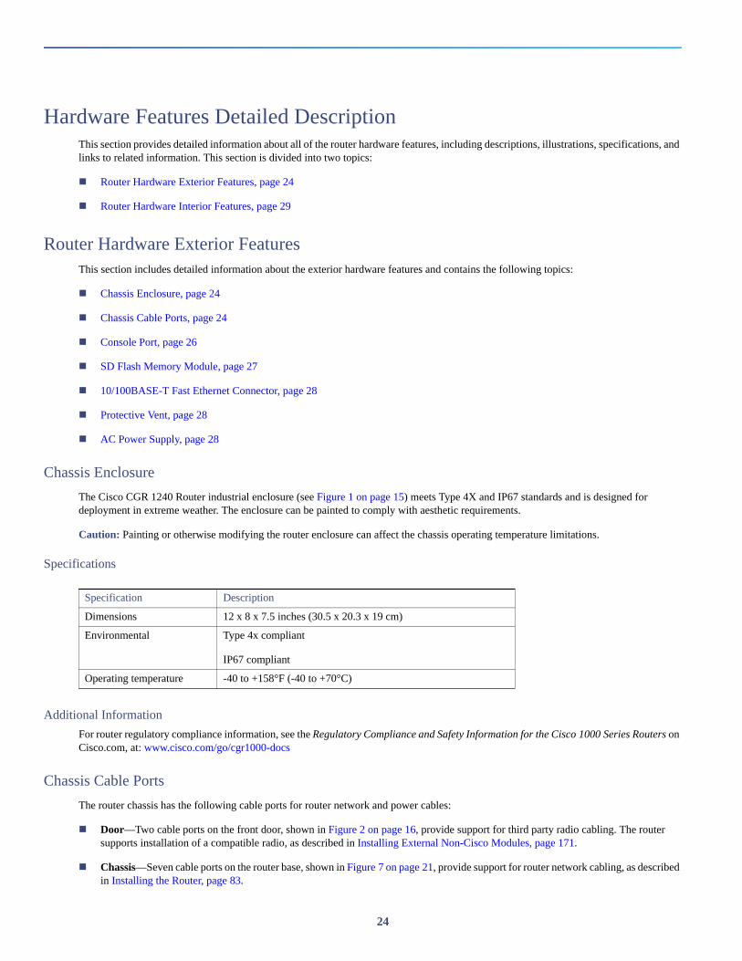
Hardware Features Detailed DescriptionThis section provides detailed information about all of the router hardware features, including descriptions, illustrations, specifications, and links to related information. This section is divided into two topics:
Router Hardware Exterior Features, page 24
Router Hardware Interior Features, page 29
Router Hardware Exterior FeaturesThis section includes detailed information about the exterior hardware features and contains the following topics:
Chassis Enclosure, page 24
Chassis Cable Ports, page 24
Console Port, page 26
SD Flash Memory Module, page 27
10/100BASE-T Fast Ethernet Connector, page 28
Protective Vent, page 28
AC Power Supply, page 28
Chassis Enclosure
The Cisco CGR 1240 Router industrial enclosure (see Figure 1 on page 15) meets Type 4X and IP67 standards and is designed for deployment in extreme weather. The enclosure can be painted to comply with aesthetic requirements.
Caution: Painting or otherwise modifying the router enclosure can affect the chassis operating temperature limitations.
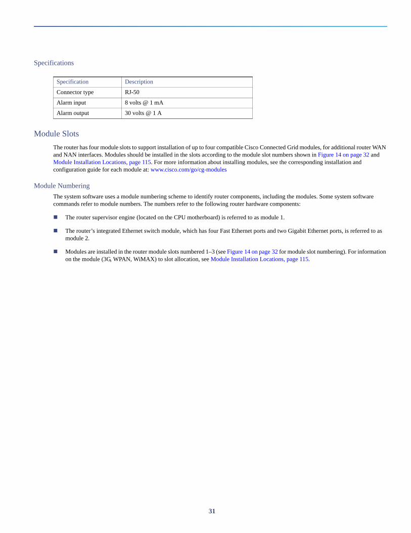
Specifications
Additional Information
For router regulatory compliance information, see the Regulatory Compliance and Safety Information for the Cisco 1000 Series Routers on Cisco.com, at: www.cisco.com/go/cgr1000-docs
Chassis Cable Ports
The router chassis has the following cable ports for router network and power cables:
Door—Two cable ports on the front door, shown in Figure 2 on page 16, provide support for third party radio cabling. The router supports installation of a compatible radio, as described in Installing External Non-Cisco Modules, page 171.
Chassis—Seven cable ports on the router base, shown in Figure 7 on page 21, provide support for router network cabling, as described in Installing the Router, page 83.
Specification Description
Dimensions 12 x 8 x 7.5 inches (30.5 x 20.3 x 19 cm)
Environmental Type 4x compliant
IP67 compliant
Operating temperature -40 to +158°F (-40 to +70°C)
24
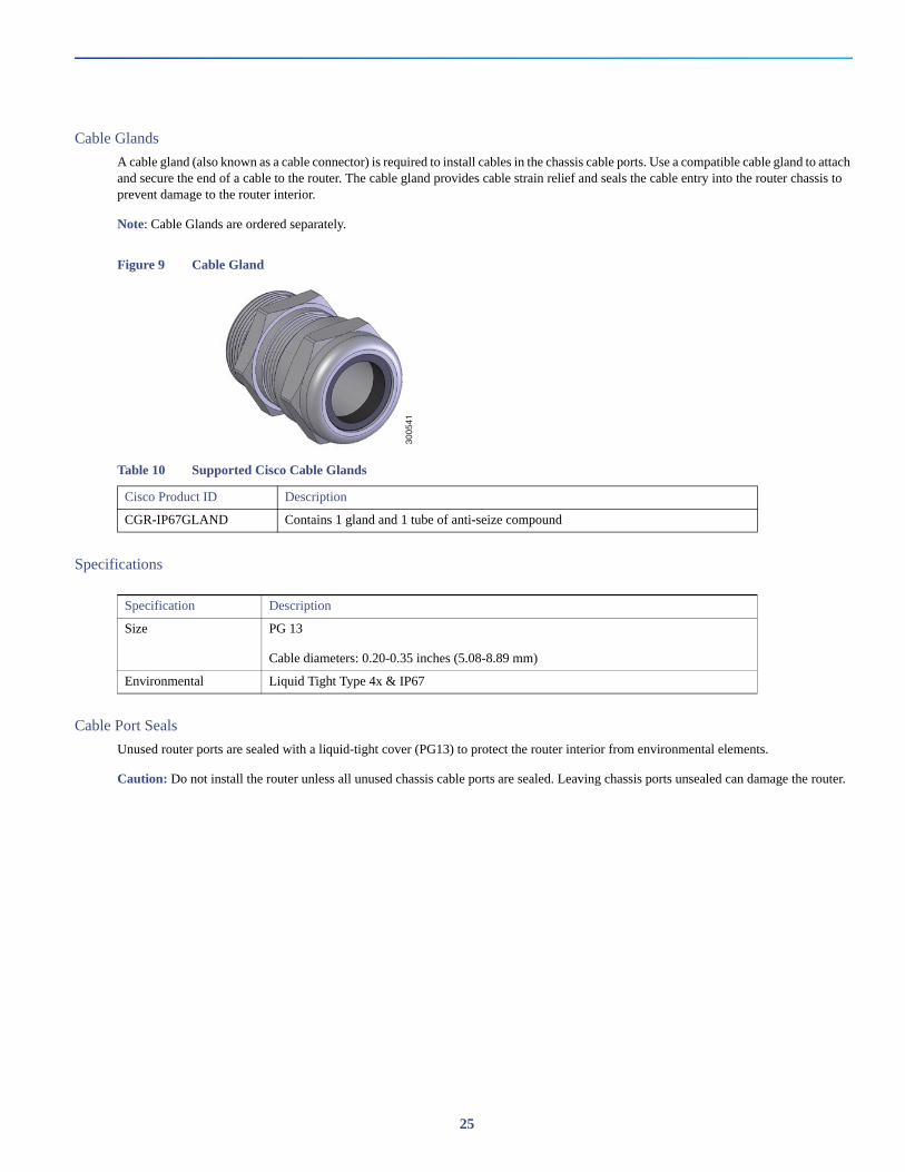
Cable Glands
A cable gland (also known as a cable connector) is required to install cables in the chassis cable ports. Use a compatible cable gland to attach and secure the end of a cable to the router. The cable gland provides cable strain relief and seals the cable entry into the router chassis to prevent damage to the router interior.
Note: Cable Glands are ordered separately.
Figure 9 Cable Gland
Specifications
Cable Port Seals
Unused router ports are sealed with a liquid-tight cover (PG13) to protect the router interior from environmental elements.
Caution: Do not install the router unless all unused chassis cable ports are sealed. Leaving chassis ports unsealed can damage the router.
Table 10 Supported Cisco Cable Glands
Cisco Product ID Description
CGR-IP67GLAND Contains 1 gland and 1 tube of anti-seize compound
3005
41
Specification Description
Size PG 13
Cable diameters: 0.20-0.35 inches (5.08-8.89 mm)
Environmental Liquid Tight Type 4x & IP67
25

Figure 10 Cable Port Seal
Console Port
The router features a single, asynchronous console port (see Figure 4 on page 18 and Figure 11 on page 27) for connecting a console or PC directly to the router. To configure the router locally, using the command-line interface (CLI), you must establish a connection to the router with a terminal session.
Caution: This port does not support cable glands; the router interior is exposed to environmental elements while the port is in use. This port should be exposed only during active terminal sessions with the router and should never be left unattended when exposed.
Note: The router also supports wireless console connections with an integrated WiFi short-range access point. For more information see, WiFi Short-Range Access Point, page 44.
Console Port Default Settings
The console port does not support hardware flow control. The default settings for the port are: 9600 baud, 8 data bits, no parity, and 1 stop bit.
Connecting to the Console Port
Your router kit includes a console cable with an RJ-45 connector on one end (for connecting to the router console port) and a DB-9 connector on the other end (for connecting to a PC or terminal).
Detailed information about connecting and using the console port is in Installing the Router, page 83.
3005
42
26
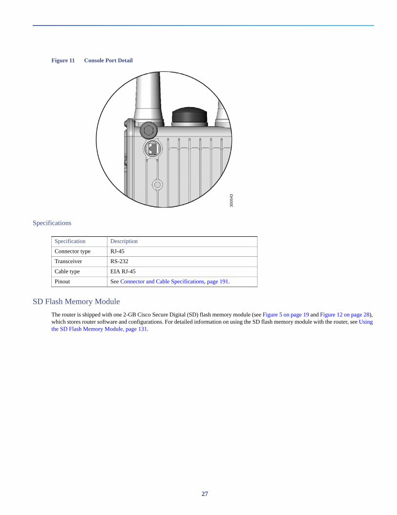
Figure 11 Console Port Detail
Specifications
SD Flash Memory Module
The router is shipped with one 2-GB Cisco Secure Digital (SD) flash memory module (see Figure 5 on page 19 and Figure 12 on page 28), which stores router software and configurations. For detailed information on using the SD flash memory module with the router, see Using the SD Flash Memory Module, page 131.
3005
43
Specification Description
Connector type RJ-45
Transceiver RS-232
Cable type EIA RJ-45
Pinout See Connector and Cable Specifications, page 191.
27
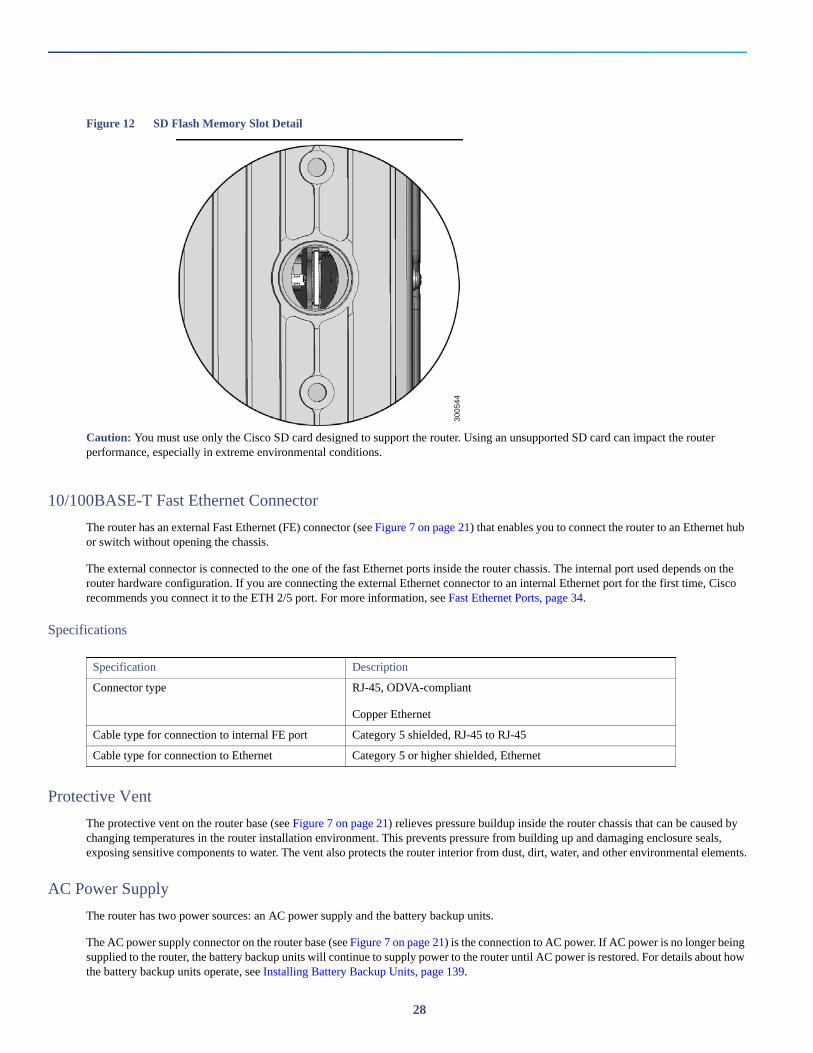
Figure 12 SD Flash Memory Slot Detail
Caution: You must use only the Cisco SD card designed to support the router. Using an unsupported SD card can impact the router performance, especially in extreme environmental conditions.
10/100BASE-T Fast Ethernet Connector
The router has an external Fast Ethernet (FE) connector (see Figure 7 on page 21) that enables you to connect the router to an Ethernet hub or switch without opening the chassis.
The external connector is connected to the one of the fast Ethernet ports inside the router chassis. The internal port used depends on the router hardware configuration. If you are connecting the external Ethernet connector to an internal Ethernet port for the first time, Cisco recommends you connect it to the ETH 2/5 port. For more information, see Fast Ethernet Ports, page 34.
Specifications
Protective Vent
The protective vent on the router base (see Figure 7 on page 21) relieves pressure buildup inside the router chassis that can be caused by changing temperatures in the router installation environment. This prevents pressure from building up and damaging enclosure seals, exposing sensitive components to water. The vent also protects the router interior from dust, dirt, water, and other environmental elements.
AC Power Supply
The router has two power sources: an AC power supply and the battery backup units.
The AC power supply connector on the router base (see Figure 7 on page 21) is the connection to AC power. If AC power is no longer being supplied to the router, the battery backup units will continue to supply power to the router until AC power is restored. For details about how the battery backup units operate, see Installing Battery Backup Units, page 139.
3005
44
Specification Description
Connector type RJ-45, ODVA-compliant
Copper Ethernet
Cable type for connection to internal FE port Category 5 shielded, RJ-45 to RJ-45
Cable type for connection to Ethernet Category 5 or higher shielded, Ethernet
28
Note: The AC power cable part number CGR-PWRCORD-NA or CGR-PWRCORD-EU must be ordered separately.
Specifications
Router Hardware Interior FeaturesThis section includes detailed information about the interior hardware features illustrated in Router Hardware Overview, page 14, and contains the following topics:
Alarm Port, page 29
Module Slots, page 31
Reset Buttons, page 32
Fast Ethernet and Gigabit Ethernet Ports, page 33
Small Form-Factor Pluggable (SFP) Ports, page 35
Combo Ports, page 37
Serial Ports, page 38
IRIG-B Timing Port, page 40
USB Ports, page 41
Memory, page 43
GPS Module, page 43
WiFi Short-Range Access Point, page 44
Alarm Port
Attach the alarm port inputs (see Figure 13 on page 30) to an alarm system to monitor external events that occur in the router’s physical installation environment (for example, indicating that the router door has been opened). Attach the alarm port outputs to an alarm indicator such as a siren or light that is enabled by a relay dry contact open or closed circuit. The port supports two alarm inputs and two alarm outputs.
The alarm-trigger setting determines when an alarm is sent to the attached alarm system.
Specification Description
Input voltage 100-240 Vrms AC
Output 60W
Cooling Convection, conduction
Operating temperature range -40 to 158°F (-40 to 70°C), external ambient
29
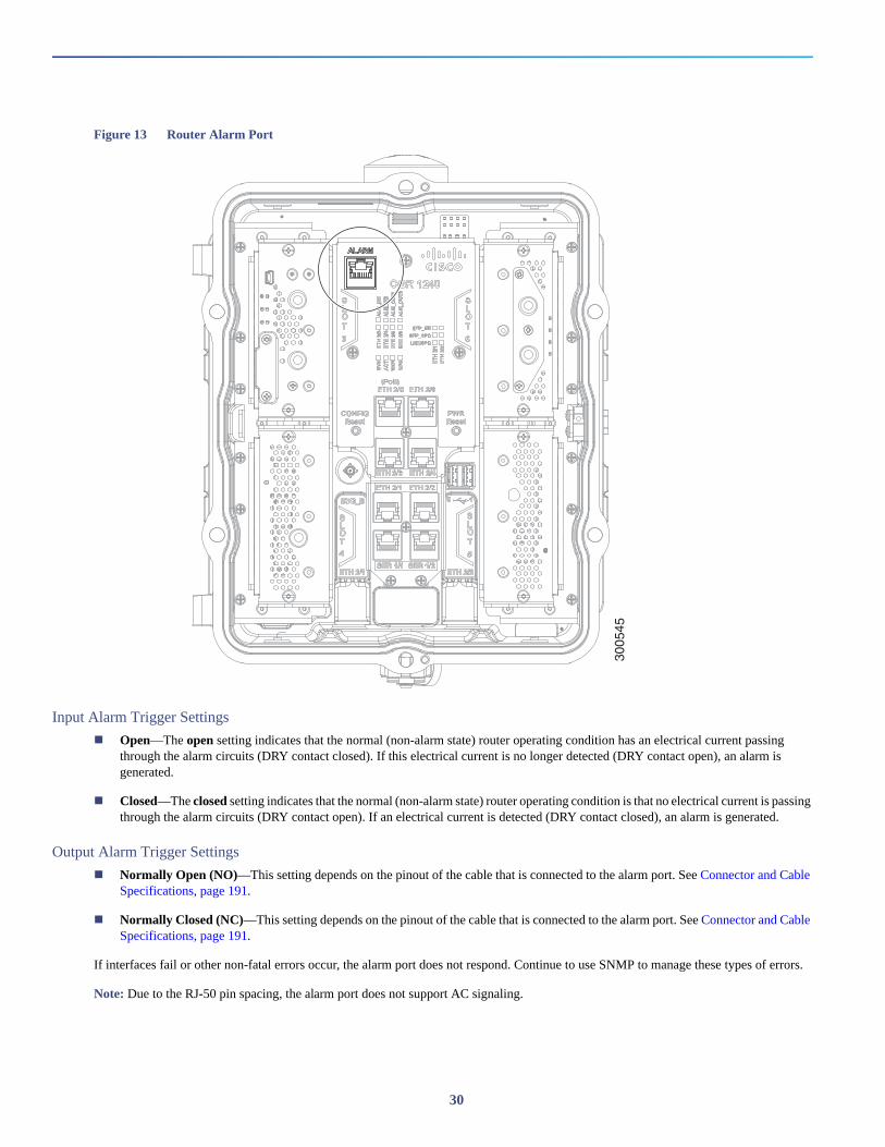
Figure 13 Router Alarm Port
Input Alarm Trigger Settings
Open—The open setting indicates that the normal (non-alarm state) router operating condition has an electrical current passing through the alarm circuits (DRY contact closed). If this electrical current is no longer detected (DRY contact open), an alarm is generated.
Closed—The closed setting indicates that the normal (non-alarm state) router operating condition is that no electrical current is passing through the alarm circuits (DRY contact open). If an electrical current is detected (DRY contact closed), an alarm is generated.
Output Alarm Trigger Settings
Normally Open (NO)—This setting depends on the pinout of the cable that is connected to the alarm port. See Connector and Cable Specifications, page 191.
Normally Closed (NC)—This setting depends on the pinout of the cable that is connected to the alarm port. See Connector and Cable Specifications, page 191.
If interfaces fail or other non-fatal errors occur, the alarm port does not respond. Continue to use SNMP to manage these types of errors.
Note: Due to the RJ-50 pin spacing, the alarm port does not support AC signaling.
3005
45
30
Specifications
Module Slots
The router has four module slots to support installation of up to four compatible Cisco Connected Grid modules, for additional router WAN and NAN interfaces. Modules should be installed in the slots according to the module slot numbers shown in Figure 14 on page 32 and Module Installation Locations, page 115. For more information about installing modules, see the corresponding installation and configuration guide for each module at: www.cisco.com/go/cg-modules
Module Numbering
The system software uses a module numbering scheme to identify router components, including the modules. Some system software commands refer to module numbers. The numbers refer to the following router hardware components:
The router supervisor engine (located on the CPU motherboard) is referred to as module 1.
The router’s integrated Ethernet switch module, which has four Fast Ethernet ports and two Gigabit Ethernet ports, is referred to as module 2.
Modules are installed in the router module slots numbered 1–3 (see Figure 14 on page 32 for module slot numbering). For information on the module (3G, WPAN, WiMAX) to slot allocation, see Module Installation Locations, page 115.
Specification Description
Connector type RJ-50
Alarm input 8 volts @ 1 mA
Alarm output 30 volts @ 1 A
31
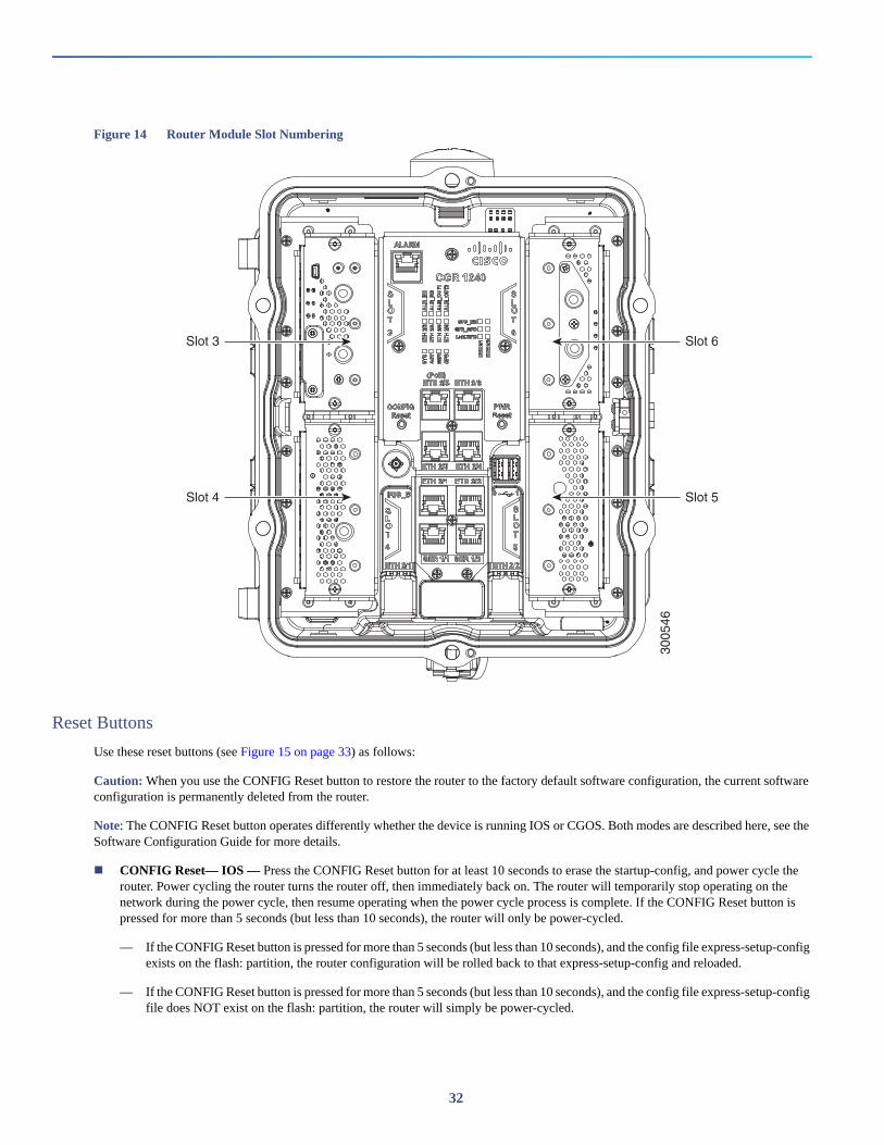
Figure 14 Router Module Slot Numbering
Reset Buttons
Use these reset buttons (see Figure 15 on page 33) as follows:
Caution: When you use the CONFIG Reset button to restore the router to the factory default software configuration, the current software configuration is permanently deleted from the router.
Note: The CONFIG Reset button operates differently whether the device is running IOS or CGOS. Both modes are described here, see the Software Configuration Guide for more details.
CONFIG Reset— IOS — Press the CONFIG Reset button for at least 10 seconds to erase the startup-config, and power cycle the router. Power cycling the router turns the router off, then immediately back on. The router will temporarily stop operating on the network during the power cycle, then resume operating when the power cycle process is complete. If the CONFIG Reset button is pressed for more than 5 seconds (but less than 10 seconds), the router will only be power-cycled.
— If the CONFIG Reset button is pressed for more than 5 seconds (but less than 10 seconds), and the config file express-setup-config exists on the flash: partition, the router configuration will be rolled back to that express-setup-config and reloaded.
— If the CONFIG Reset button is pressed for more than 5 seconds (but less than 10 seconds), and the config file express-setup-config file does NOT exist on the flash: partition, the router will simply be power-cycled.
3005
46
Slot 3
Slot 4
Slot 6
Slot 5
32
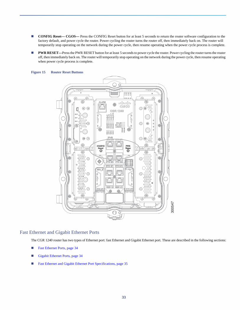
CONFIG Reset— CGOS— Press the CONFIG Reset button for at least 5 seconds to return the router software configuration to the factory default, and power cycle the router. Power cycling the router turns the router off, then immediately back on. The router will temporarily stop operating on the network during the power cycle, then resume operating when the power cycle process is complete.
PWR RESET—Press the PWR RESET button for at least 5 seconds to power cycle the router. Power cycling the router turns the router off, then immediately back on. The router will temporarily stop operating on the network during the power cycle, then resume operating when power cycle process is complete.
Figure 15 Router Reset Buttons
Fast Ethernet and Gigabit Ethernet Ports
The CGR 1240 router has two types of Ethernet port: fast Ethernet and Gigabit Ethernet port. These are described in the following sections:
Fast Ethernet Ports, page 34
Gigabit Ethernet Ports, page 34
Fast Ethernet and Gigabit Ethernet Port Specifications, page 35
3005
47
33
Fast Ethernet Ports
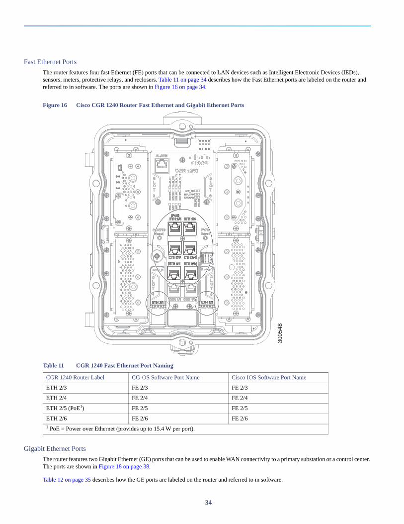
The router features four fast Ethernet (FE) ports that can be connected to LAN devices such as Intelligent Electronic Devices (IEDs), sensors, meters, protective relays, and reclosers. Table 11 on page 34 describes how the Fast Ethernet ports are labeled on the router and referred to in software. The ports are shown in Figure 16 on page 34.
Figure 16 Cisco CGR 1240 Router Fast Ethernet and Gigabit Ethernet Ports
Gigabit Ethernet Ports
The router features two Gigabit Ethernet (GE) ports that can be used to enable WAN connectivity to a primary substation or a control center. The ports are shown in Figure 18 on page 38.
Table 12 on page 35 describes how the GE ports are labeled on the router and referred to in software.
Table 11 CGR 1240 Fast Ethernet Port Naming
CGR 1240 Router Label CG-OS Software Port Name Cisco IOS Software Port Name
ETH 2/3 FE 2/3 FE 2/3
ETH 2/4 FE 2/4 FE 2/4
ETH 2/5 (PoE1) FE 2/5 FE 2/5
ETH 2/6 FE 2/6 FE 2/61 PoE = Power over Ethernet (provides up to 15.4 W per port).
3005
48
34
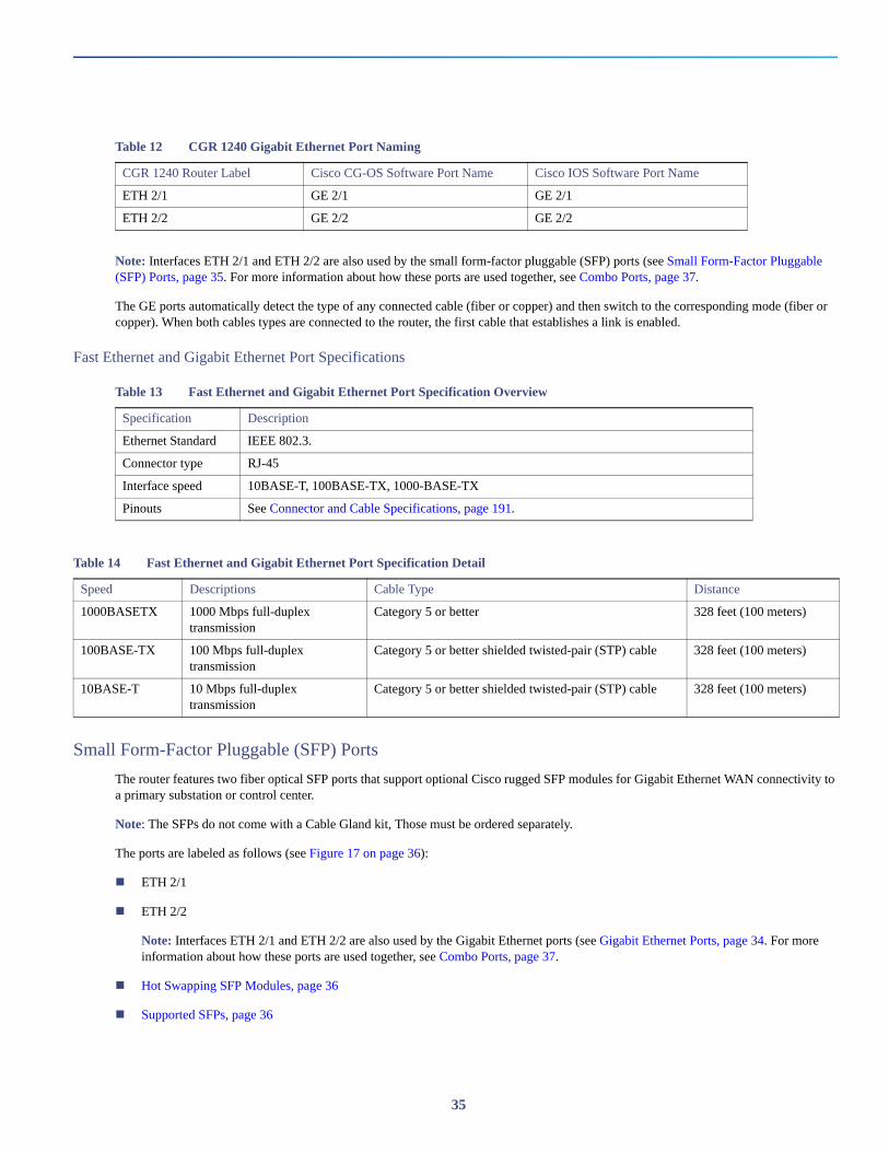
Note: Interfaces ETH 2/1 and ETH 2/2 are also used by the small form-factor pluggable (SFP) ports (see Small Form-Factor Pluggable (SFP) Ports, page 35. For more information about how these ports are used together, see Combo Ports, page 37.
The GE ports automatically detect the type of any connected cable (fiber or copper) and then switch to the corresponding mode (fiber or copper). When both cables types are connected to the router, the first cable that establishes a link is enabled.
Fast Ethernet and Gigabit Ethernet Port Specifications
Small Form-Factor Pluggable (SFP) Ports
The router features two fiber optical SFP ports that support optional Cisco rugged SFP modules for Gigabit Ethernet WAN connectivity to a primary substation or control center.
Note: The SFPs do not come with a Cable Gland kit, Those must be ordered separately.
The ports are labeled as follows (see Figure 17 on page 36):
ETH 2/1
ETH 2/2
Note: Interfaces ETH 2/1 and ETH 2/2 are also used by the Gigabit Ethernet ports (see Gigabit Ethernet Ports, page 34. For more information about how these ports are used together, see Combo Ports, page 37.
Hot Swapping SFP Modules, page 36
Supported SFPs, page 36
Table 12 CGR 1240 Gigabit Ethernet Port Naming
CGR 1240 Router Label Cisco CG-OS Software Port Name Cisco IOS Software Port Name
ETH 2/1 GE 2/1 GE 2/1
ETH 2/2 GE 2/2 GE 2/2
Table 13 Fast Ethernet and Gigabit Ethernet Port Specification Overview
Specification Description
Ethernet Standard IEEE 802.3.
Connector type RJ-45
Interface speed 10BASE-T, 100BASE-TX, 1000-BASE-TX
Pinouts See Connector and Cable Specifications, page 191.
Table 14 Fast Ethernet and Gigabit Ethernet Port Specification Detail
Speed Descriptions Cable Type Distance
1000BASETX 1000 Mbps full-duplex transmission
Category 5 or better 328 feet (100 meters)
100BASE-TX 100 Mbps full-duplex transmission
Category 5 or better shielded twisted-pair (STP) cable 328 feet (100 meters)
10BASE-T 10 Mbps full-duplex transmission
Category 5 or better shielded twisted-pair (STP) cable 328 feet (100 meters)
35
Specifications, page 37
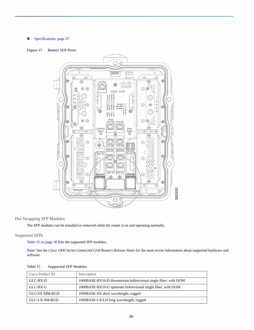
Figure 17 Router SFP Ports
Hot Swapping SFP Modules
The SFP modules can be installed or removed while the router is on and operating normally.
Supported SFPs
Table 15 on page 36 lists the supported SFP modules.
Note: See the Cisco 1000 Series Connected Grid Routers Release Notes for the most recent information about supported hardware and software.
3005
50
Table 15 Supported SFP Modules
Cisco Product ID Description
GLC-BX-D 1000BASE-BX10-D downstream bidirectional single fiber; with DOM
GLC-BX-U 1000BASE-BX10-U upstream bidirectional single fiber; with DOM
GLC-SX-MM-RGD 1000BASE-SX short wavelength; rugged
GLC-LX-SM-RGD 1000BASE-LX/LH long wavelength; rugged
36
Specifications
Combo Ports
The combo ports are two Gigabit Ethernet ports and two SFP ports on the router that are labeled identically. Figure 18 on page 38 shows the ports.
The GE and SFP ports share the same physical ports or connections and are labeled identically on the router (ETH 2/1, ETH 2/2) and in the software (GE 2/1, GE 2/2). Table 16 on page 38 describes the port naming on the router and in software.
The Gigabit Ethernet ports support copper GE connections and the SFP modules support fiber optic GE connections. Only one connection on each interface (ETH 2/1 and ETH 2/2) can be in use at any time.
These ports automatically detect the type of any connected cable (fiber or copper) and then switch to the corresponding mode (fiber or copper).
Note: If connections are made to both interfaces of the same name (ETH 2/1 or ETH 2/2), only the first connection that establishes a link is enabled.
GLC-ZX-SM-RGD 1000BASE-ZX extended distance; rugged
GLC-FE-100FX-RGD 100BASE-FX SFP; rugged
GLC-FE-100LX-RGD 100BASE-LX10 SFP; rugged
Table 15 Supported SFP Modules (continued)
Specification Description
Connector type LC
Optical Interface 100Base-FX, LX; 1000Base-SX, LX, ZX
Coding Scheme SFP modules:
1000 Mbps 8B/10B coding
100 Mbps 4B/5B coding
Pinouts See Connector and Cable Specifications, page 191.
37
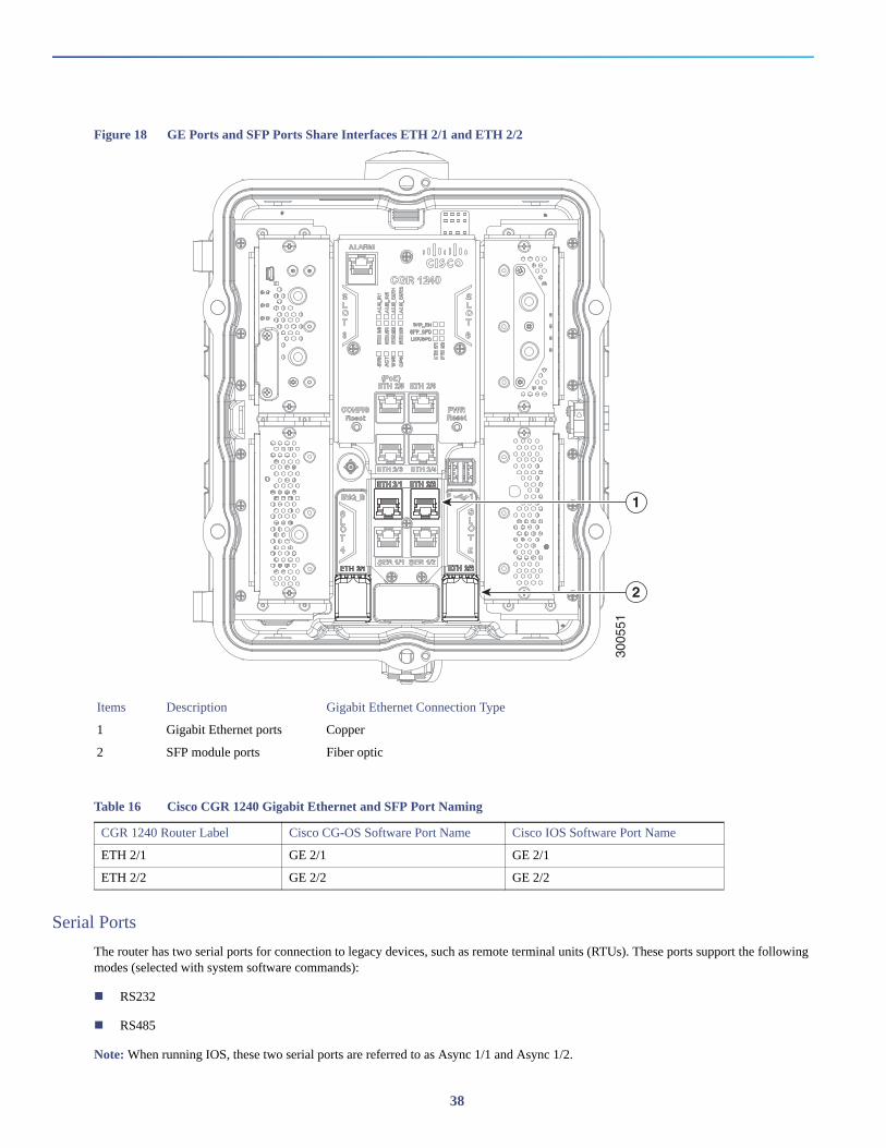
Figure 18 GE Ports and SFP Ports Share Interfaces ETH 2/1 and ETH 2/2
Serial Ports
The router has two serial ports for connection to legacy devices, such as remote terminal units (RTUs). These ports support the following modes (selected with system software commands):
RS232
RS485
Note: When running IOS, these two serial ports are referred to as Async 1/1 and Async 1/2.
Items Description Gigabit Ethernet Connection Type
1 Gigabit Ethernet ports Copper
2 SFP module ports Fiber optic
Table 16 Cisco CGR 1240 Gigabit Ethernet and SFP Port Naming
CGR 1240 Router Label Cisco CG-OS Software Port Name Cisco IOS Software Port Name
ETH 2/1 GE 2/1 GE 2/1
ETH 2/2 GE 2/2 GE 2/2
3005
51
1
2
38
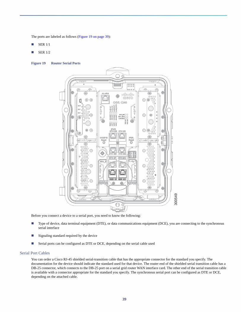
The ports are labeled as follows (Figure 19 on page 39):
SER 1/1
SER 1/2
Figure 19 Router Serial Ports
Before you connect a device to a serial port, you need to know the following:
Type of device, data terminal equipment (DTE), or data communications equipment (DCE), you are connecting to the synchronous serial interface
Signaling standard required by the device
Serial ports can be configured as DTE or DCE, depending on the serial cable used
Serial Port Cables
You can order a Cisco RJ-45 shielded serial-transition cable that has the appropriate connector for the standard you specify. The documentation for the device should indicate the standard used for that device. The router end of the shielded serial transition cable has a DB-25 connector, which connects to the DB-25 port on a serial grid router WAN interface card. The other end of the serial transition cable is available with a connector appropriate for the standard you specify. The synchronous serial port can be configured as DTE or DCE, depending on the attached cable.
3005
49
39
Specifications
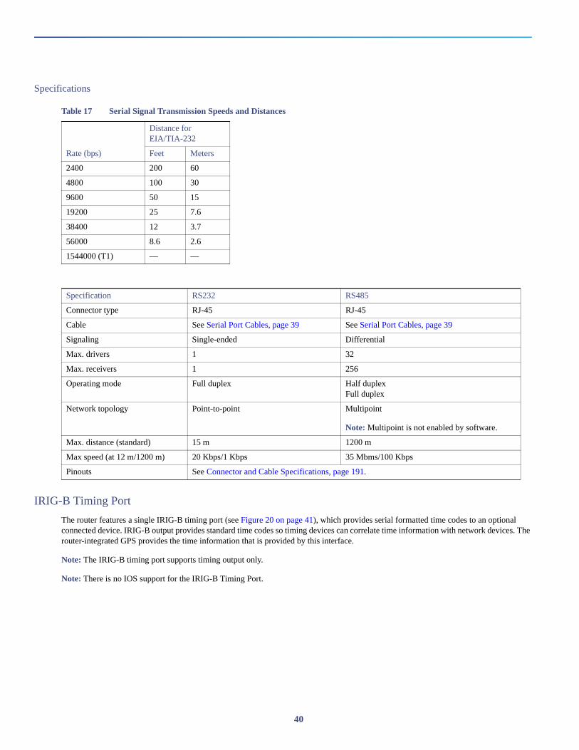
IRIG-B Timing Port
The router features a single IRIG-B timing port (see Figure 20 on page 41), which provides serial formatted time codes to an optional connected device. IRIG-B output provides standard time codes so timing devices can correlate time information with network devices. The router-integrated GPS provides the time information that is provided by this interface.
Note: The IRIG-B timing port supports timing output only.
Note: There is no IOS support for the IRIG-B Timing Port.
Table 17 Serial Signal Transmission Speeds and Distances
Distance for EIA/TIA-232
Rate (bps) Feet Meters
2400 200 60
4800 100 30
9600 50 15
19200 25 7.6
38400 12 3.7
56000 8.6 2.6
1544000 (T1) — —
Specification RS232 RS485
Connector type RJ-45 RJ-45
Cable See Serial Port Cables, page 39 See Serial Port Cables, page 39
Signaling Single-ended Differential
Max. drivers 1 32
Max. receivers 1 256
Operating mode Full duplex Half duplexFull duplex
Network topology Point-to-point Multipoint
Note: Multipoint is not enabled by software.
Max. distance (standard) 15 m 1200 m
Max speed (at 12 m/1200 m) 20 Kbps/1 Kbps 35 Mbms/100 Kbps
Pinouts See Connector and Cable Specifications, page 191.
40
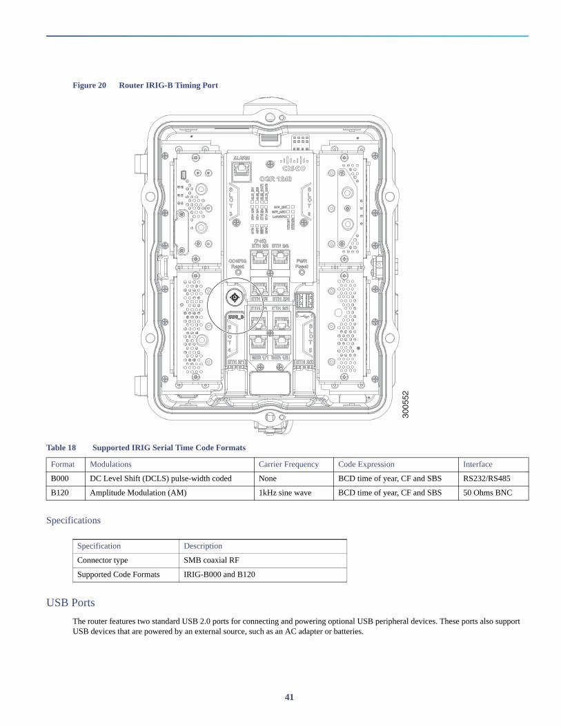
Figure 20 Router IRIG-B Timing Port
Specifications
USB Ports
The router features two standard USB 2.0 ports for connecting and powering optional USB peripheral devices. These ports also support USB devices that are powered by an external source, such as an AC adapter or batteries.
3005
52
Table 18 Supported IRIG Serial Time Code Formats
Format Modulations Carrier Frequency Code Expression Interface
B000 DC Level Shift (DCLS) pulse-width coded None BCD time of year, CF and SBS RS232/RS485
B120 Amplitude Modulation (AM) 1kHz sine wave BCD time of year, CF and SBS 50 Ohms BNC
Specification Description
Connector type SMB coaxial RF
Supported Code Formats IRIG-B000 and B120
41
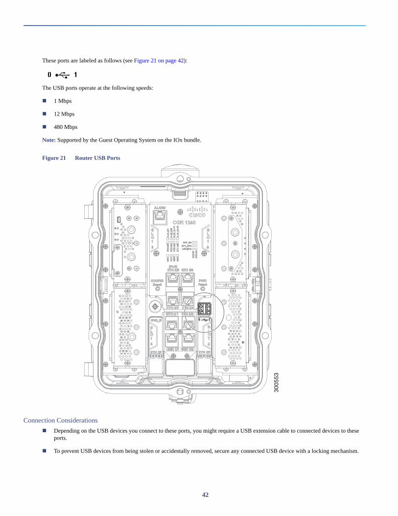
These ports are labeled as follows (see Figure 21 on page 42):
The USB ports operate at the following speeds:
1 Mbps
12 Mbps
480 Mbps
Note: Supported by the Guest Operating System on the IOx bundle.
Figure 21 Router USB Ports
Connection Considerations
Depending on the USB devices you connect to these ports, you might require a USB extension cable to connected devices to these ports.
To prevent USB devices from being stolen or accidentally removed, secure any connected USB device with a locking mechanism.
3005
53
42
Specifications
Memory
SD Flash Memory
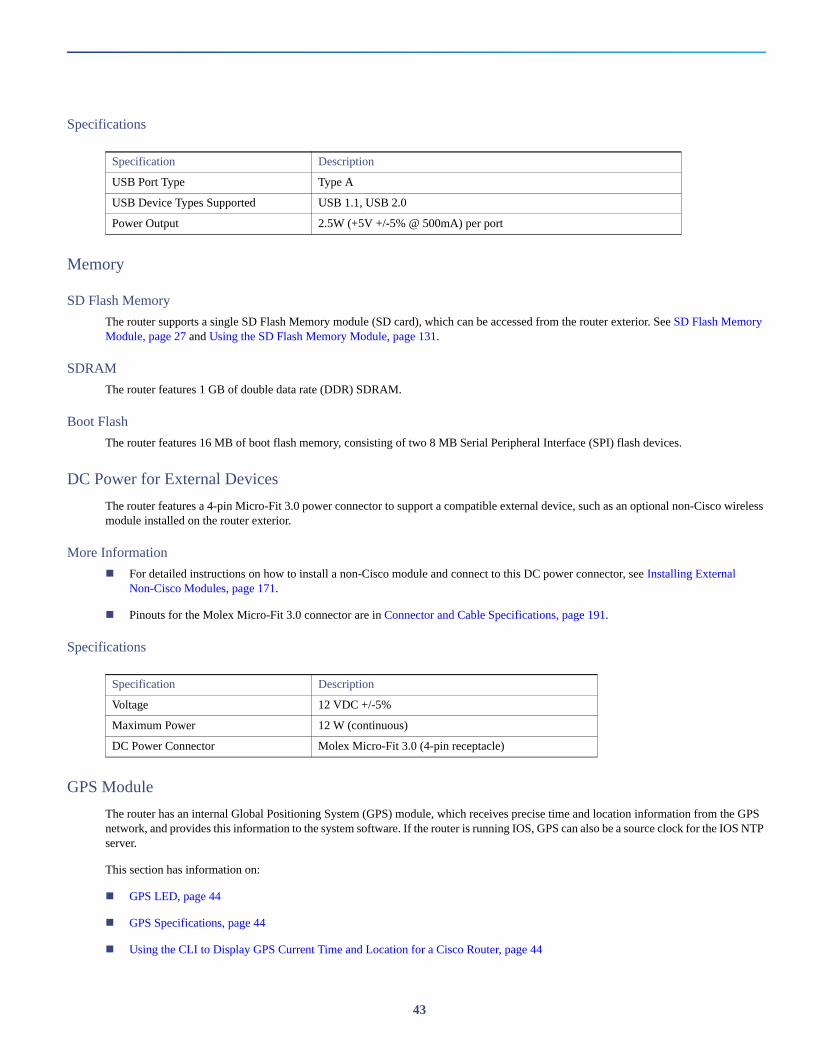
The router supports a single SD Flash Memory module (SD card), which can be accessed from the router exterior. See SD Flash Memory Module, page 27 and Using the SD Flash Memory Module, page 131.
SDRAM
The router features 1 GB of double data rate (DDR) SDRAM.
Boot Flash
The router features 16 MB of boot flash memory, consisting of two 8 MB Serial Peripheral Interface (SPI) flash devices.
DC Power for External Devices
The router features a 4-pin Micro-Fit 3.0 power connector to support a compatible external device, such as an optional non-Cisco wireless module installed on the router exterior.
More Information
For detailed instructions on how to install a non-Cisco module and connect to this DC power connector, see Installing External Non-Cisco Modules, page 171.
Pinouts for the Molex Micro-Fit 3.0 connector are in Connector and Cable Specifications, page 191.
Specifications
GPS Module
The router has an internal Global Positioning System (GPS) module, which receives precise time and location information from the GPS network, and provides this information to the system software. If the router is running IOS, GPS can also be a source clock for the IOS NTP server.
This section has information on:
GPS LED, page 44
GPS Specifications, page 44
Using the CLI to Display GPS Current Time and Location for a Cisco Router, page 44
Specification Description
USB Port Type Type A
USB Device Types Supported USB 1.1, USB 2.0
Power Output 2.5W (+5V +/-5% @ 500mA) per port
Specification Description
Voltage 12 VDC +/-5%
Maximum Power 12 W (continuous)
DC Power Connector Molex Micro-Fit 3.0 (4-pin receptacle)
43
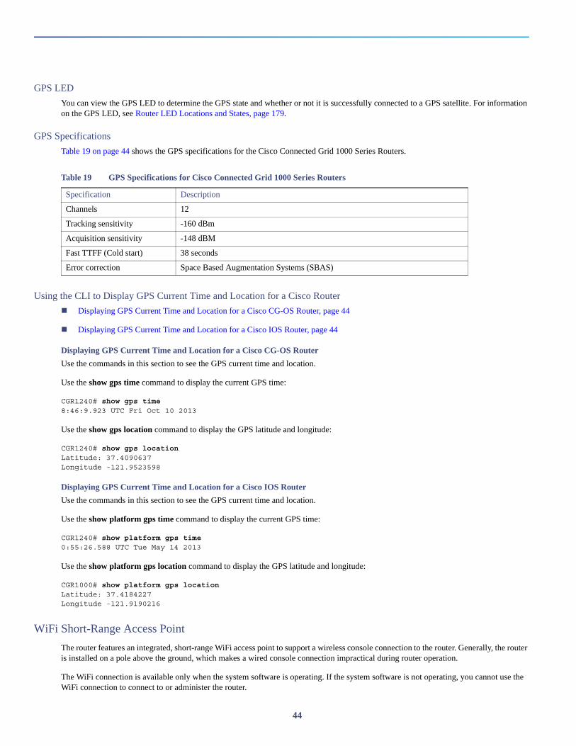
GPS LED
You can view the GPS LED to determine the GPS state and whether or not it is successfully connected to a GPS satellite. For information on the GPS LED, see Router LED Locations and States, page 179.
GPS Specifications
Table 19 on page 44 shows the GPS specifications for the Cisco Connected Grid 1000 Series Routers.
Using the CLI to Display GPS Current Time and Location for a Cisco Router
Displaying GPS Current Time and Location for a Cisco CG-OS Router, page 44
Displaying GPS Current Time and Location for a Cisco IOS Router, page 44
Displaying GPS Current Time and Location for a Cisco CG-OS Router
Use the commands in this section to see the GPS current time and location.
Use the show gps time command to display the current GPS time:
CGR1240# show gps time8:46:9.923 UTC Fri Oct 10 2013
Use the show gps location command to display the GPS latitude and longitude:
CGR1240# show gps locationLatitude: 37.4090637Longitude -121.9523598
Displaying GPS Current Time and Location for a Cisco IOS Router
Use the commands in this section to see the GPS current time and location.
Use the show platform gps time command to display the current GPS time:
CGR1240# show platform gps time0:55:26.588 UTC Tue May 14 2013
Use the show platform gps location command to display the GPS latitude and longitude:
CGR1000# show platform gps locationLatitude: 37.4184227Longitude -121.9190216
WiFi Short-Range Access Point
The router features an integrated, short-range WiFi access point to support a wireless console connection to the router. Generally, the router is installed on a pole above the ground, which makes a wired console connection impractical during router operation.
The WiFi connection is available only when the system software is operating. If the system software is not operating, you cannot use the WiFi connection to connect to or administer the router.
Table 19 GPS Specifications for Cisco Connected Grid 1000 Series Routers
Specification Description
Channels 12
Tracking sensitivity -160 dBm
Acquisition sensitivity -148 dBM
Fast TTFF (Cold start) 38 seconds
Error correction Space Based Augmentation Systems (SBAS)
44
When running IOS, Wi-Fi can be used as an access point for up to 5 devices, but also as a layer-3 interface.
WiFi Hardware
The CGR 1240 router is equipped with an 802.11b/g/n 2.4GHz radio that works as the access point to provide WiFi connectivity to the router. The WiFi hardware is a Broadcom BCM4325 chipset based radio with an external WiFi antenna.
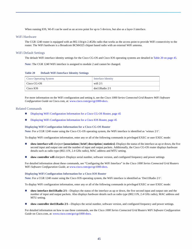
WiFi Default Settings
The default WiFi interface identity settings for the Cisco CG-OS and Cisco IOS operating systems are detailed in Table 20 on page 45.
Note: The CGR 1240 WiFi interface is assigned to module 2 and cannot be changed.
For more information on the WiFi configuration and setting it, see the Cisco 1000 Series Connected Grid Routers WiFi Software Configuration Guide on Cisco.com, at: www.cisco.com/go/cgr1000-docs.
Related Commands
Displaying WiFi Configuration Information for a Cisco CG-OS Router, page 45
Displaying WiFi Configuration Information for a Cisco IOS Router, page 45
Displaying WiFi Configuration Information for a Cisco CG-OS Router
Note: For a CGR 1240 router using the Cisco CG-OS operating system, the WiFi interface is identified as ‘wimax 2/1’.
To display WiFi configuration information, enter any or all of the following commands in privileged EXEC or user EXEC mode:
show interface wifi slot/port [associations | brief | description | statistics]–Displays the status of the interface as up or down, the five second input and output rate and the number of input and output packets. Additionally, the Cisco CG-OS router displays hardware details such as radio type (802.11N, 2.4 GHz radio), MAC address and MTU setting.
show controller wifi slot/port–Displays serial number, software version, and configured frequency and power settings
For detailed information about these commands, see “Configuring the WiFi Interface” in the Cisco 1000 Series Connected Grid Routers WiFi Software Configuration Guide, at www.cisco.com/go/cgr1000-docs.
Displaying WiFi Configuration Information for a Cisco IOS Router
Note: For a CGR 1240 router using the Cisco IOS operating system, the WiFi interface is identified as ‘Dot11Radio 2/1’.
To display WiFi configuration information, enter any or all of the following commands in privileged EXEC or user EXEC mode:
show interface dot11Radio 2/1—Displays the status of the interface as up or down, the five second input and output rate and the number of input and output packets. Also displays hardware details such as radio type (802.11N, 2.4 GHz radio), MAC address and MTU setting.
show controller dot11Radio 2/1—Displays the serial number, software version, and configured frequency and power settings.
For detailed information on how to use these commands, see the Cisco 1000 Series Connected Grid Routers WiFi Software Configuration Guide on Cisco.com, at: www.cisco.com/go/cgr1000-docs.
Table 20 Default WiFi Interface Identity Settings
Cisco Operating System Interface Identity
Cisco CG-OS wifi 2/1
Cisco IOS dot11Radio 2/1
45

Real-Time Clock (RTC)
The router features an integrated real-time clock (RTC) with battery backup that supplies the system software with accurate date and time information.
Temperature Sensor
The router hardware features an internal temperature sensor used by the router software to monitor the system operating temperature. The router can be configured to generate alerts when the temperature falls outside of a user-defined temperature range. The router can also be configured to store historical temperature data.
For more information about monitoring and storing router temperature data, see the router configuration guide on Cisco.com at: www.cisco.com/go/cgr1000-docs
46