Embed Size (px)
Citation preview

INSTRUCTION MANUAL
Detcon Model IR-700
IR700 Combustible Gas Sensor This manual covers the 0-100% LEL range
IR-700 CO2 Carbon Dioxide Gas Sensor This manual covers all ranges of the IR-700 CO2 Sensor
320The W
Ph.281.3
February 29, 2008 • Document #3169 • Revision 2.0
DETCON, Inc. 0 Research Forest Dr., oodlands, Texas 77387
67.4100 / Fax 281.298.2868 www.detcon.com

Model IR-700
Model IR-700 ii
This page left intentionally blank

Model IR-700
Model IR-700 iii
Table of Contents 1. Introduction ..................................................................................................................................................1
1.1 Description.......................................................................................................................................... 1 1.2 Sensor Electronics Design .................................................................................................................. 3 1.3 Modular Mechanical Design............................................................................................................... 3 1.4 Plug-in Replaceable Sensor ................................................................................................................ 4
2. Installation ....................................................................................................................................................5 2.1 ATEX Operational Guidelines for Safe Use....................................................................................... 5 2.2 Sensor Placement ................................................................................................................................ 5 2.3 Sensor Contaminants and Interference ............................................................................................... 7 2.4 Mounting Installation.......................................................................................................................... 7 2.5 Electrical Installation .......................................................................................................................... 8 2.6 Field Wiring ........................................................................................................................................ 9 2.7 Initial Start Up................................................................................................................................... 11
3. Operation ....................................................................................................................................................12 3.1 Programming Magnet Operating Instructions................................................................................... 12 3.2 Operator Interface ............................................................................................................................. 13 3.3 Normal Operation ............................................................................................................................. 14 3.4 Calibration Mode (AutoZero and AutoSpan) ................................................................................... 15
3.4.1 AutoZero....................................................................................................................................... 15 3.4.2 AutoSpan ...................................................................................................................................... 15
3.5 Program Mode .................................................................................................................................. 17 3.5.1 View Sensor Status....................................................................................................................... 18 3.5.2 Set AutoSpan Level ...................................................................................................................... 19 3.5.3 Set Gas Type & Range ................................................................................................................. 19 3.5.4 Set Gas Factor............................................................................................................................... 20 3.5.5 Set Serial ID ................................................................................................................................. 21 3.5.6 Set Sensor Gain ............................................................................................................................ 21 3.5.7 Signal Output Check..................................................................................................................... 22 3.5.8 Restore Factory Defaults .............................................................................................................. 22
3.6 Program Features .............................................................................................................................. 23 3.6.1 Operational Features..................................................................................................................... 23 3.6.2 Fault Diagnostic/Fail-Safe Features ............................................................................................. 24
4. RS-485 Modbus™ Protocol .......................................................................................................................27 5. Service and Maintenance............................................................................................................................29 6. Troubleshooting Guide...............................................................................................................................31 7. Customer Support and Service Policy ........................................................................................................34 8. IR-700 Sensor Warranty.............................................................................................................................35 9. Appendix ....................................................................................................................................................36
9.1 Specifications.................................................................................................................................... 36 9.2 Spare Parts, Sensor Accessories, Calibration Equipment ................................................................. 37 9.3 Model IR-700 Engineering Drawings............................................................................................... 38
Table of Figures Figure 1 Sensor Cell Construction ....................................................................................................................... 1 Figure 2 Principle of Operation............................................................................................................................ 2 Figure 3 Response Curve ..................................................................................................................................... 2 Figure 4 ITM Circuit Functional Block Diagram................................................................................................. 3 Figure 5 Sensor Assembly Front View ................................................................................................................ 3 Figure 6 Sensor Assembly Breakaway................................................................................................................. 4

Model IR-700
Model IR-700 iv
Figure 7 IR Sensor Cell ........................................................................................................................................ 4 Figure 8 ATEX Approval Label........................................................................................................................... 5 Figure 9 Outline and Mounting Dimensions ........................................................................................................ 8 Figure 10 Typical Installation .............................................................................................................................. 9 Figure 11 Sensor Wire Connections................................................................................................................... 10 Figure 12 Magnetic Programming Tool ............................................................................................................. 12 Figure 13 Magnetic Programming Switches ...................................................................................................... 12 Figure 14 IR-700 Software Flowchart............................................................................................................... 14 Figure 15 Sensor Assembly................................................................................................................................ 29
Shipping Address: 3200 A-1 Research Forest Dr., The Woodlands Texas 77381 Mailing Address: P.O. Box 8067, The Woodlands Texas 77387-8067
Phone: 888.367.4286, 281.367.4100 • Fax: 281.292.2860 • www.detcon.com • [email protected]

Model IR-700
1. Introduction
1.1 Description Detcon Model IR-700 combustible gas sensors are non-intrusive “Smart” sensors designed to detect and monitor combustible hydrocarbon gases in air. The range of detection is 0-100% LEL. The Model IR-700 CO2 Sensor is designed to detect CO2 in air at ranges from 0-.3% to 0-100% by Volume. The sensor features an LED display of current reading, fault and calibration status. The unit is equipped with standard analog 4-20mA and Modbus™ RS-485 outputs. A primary feature of the sensor is its method of automatic calibration, which guides the user through each step via fully scripted instructions shown on the LED display. The microprocessor-supervised electronics are packaged in an encapsulated module and housed in an explosion proof casting. The unit includes a 4 character alpha/numeric LED used to display sensor readings, and the sensor’s menu-driven interface when the hand-held programming magnet is used.
Non-Dispersive Infrared (NDIR) Optical Sensor Technology
The sensor technology is designed as a miniature plug-in replaceable component, which can easily be changed out in the field. The NDIR sensor consists of an infrared lamp source, two pyroelectric detectors, and an optical gas sample chamber. The lamp source produces infrared radiation, which interacts with the target gas as it is reflected through the optical gas sample chamber. The infrared radiation contacts each of the two pyroelectric detectors at the completion of the optical path. The “active” pyroelectric detector is covered by a filter specific to the part of the IR spectrum where the target gas absorbs light. The “reference” pyroelectric detector is covered by a filter specific to the non-absorbing part of the IR spectrum. When the target gas is present, it absorbs IR radiation and the signal output from the active detective decreases accordingly. The reference detector output remains unchanged. The ratio of the active and reference detector outputs are then used to compute the target gas concentration. The technique is referred to as non-selective and may be used to monitor most any combustible hydrocarbon gas. The technique for CO2 is similar except that the sensor provides a selective response to CO2. Unlike catalytic bead type sensors, Detcon IR sensors are completely resistant to poisoning from corrosive gases and they can operate in the absence of an oxygen background. The sensors are characteristically stable and capable of providing reliable performance for periods exceeding 5 years in most industrial environments.
Figure 1 Sensor Cell Construction
IR-700 Instruction Manual Rev. 2.0 Page 1 of 38

Model IR-700
Principle of Operation
The target gas diffuses through a sintered stainless steel flame arrestor and into the volume of the sample gas optical chamber. An alternating miniature lamp provides a cyclical IR radiation source, which reflects through the optical gas sample chamber and terminates at two pyroelectric detectors. The active and reference pyroelectric detectors each give an output which measures the intensity of the radiation contacting their surface. The active detector is covered by an optical filter specific to the part of the IR spectrum where the target gas absorbs light. The reference detector is covered by a filter specific to the non-absorbing part of the IR spectrum. When present, the target gas absorbs a fraction of the IR radiation and the signal output from the active detector decreases accordingly. The signal output of the reference detector remains unchanged in the presence of the target gas. The ratio of the active/reference signal outputs is then used to compute the target gas concentration. By using the ratio of the active/reference signal outputs, measurement drift caused by the changes in the intensity of the IR lamp source or changes in the optical path’s reflectivity is prevented.
Figure 2 Principle of Operation
Performance Characteristics
The IR sensor maintains strong sensitivity to most all combustible hydrocarbon gases in the Lower Explosive Limit (LEL) range, as shown in the response curve illustration below. When compared with the typical catalytic bead LEL sensor, the IR sensor exhibits improved long-term zero and span stability. Typical zero calibration intervals would be quarterly to semi-annual and typical span intervals would be semi-annual to annual. However, actual field experience is always the best determination of appropriate calibration intervals.
NOTE: The IR-700 sensor will not respond to combustible gases that are not hydrocarbons, such as H2, NH3, CO, H2S….etc. It can only be used to measure hydrocarbon type gases.
The IR sensor generates different signal sensitivity levels for different combustible hydrocarbon target gases. Unless otherwise specified the IR-700 sensor will be factory calibrated for methane service. If the target hydrocarbon gas is other than methane, then the unit will have to be span calibrated and configured accordingly per this Instruction Manual.
Figure 3 Response Curve
IR-700 Instruction Manual Rev. 2.0 Page 2 of 38
Model IR-700
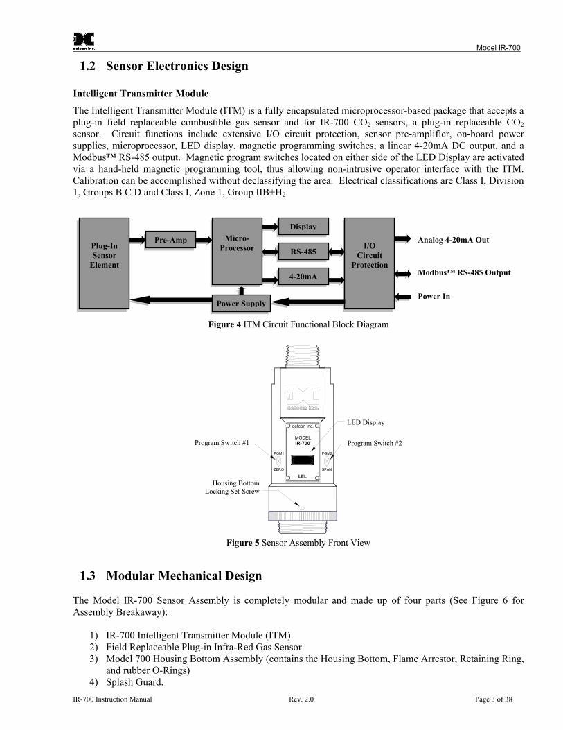
1.2 Sensor Electronics Design Intelligent Transmitter Module
The Intelligent Transmitter Module (ITM) is a fully encapsulated microprocessor-based package that accepts a plug-in field replaceable combustible gas sensor and for IR-700 CO2 sensors, a plug-in replaceable CO2 sensor. Circuit functions include extensive I/O circuit protection, sensor pre-amplifier, on-board power supplies, microprocessor, LED display, magnetic programming switches, a linear 4-20mA DC output, and a Modbus™ RS-485 output. Magnetic program switches located on either side of the LED Display are activated via a hand-held magnetic programming tool, thus allowing non-intrusive operator interface with the ITM. Calibration can be accomplished without declassifying the area. Electrical classifications are Class I, Division 1, Groups B C D and Class I, Zone 1, Group IIB+H2.
I/O Circuit
Micro-
Processor
P
Plug-In Sensor
Element
P
DAnalog 4-20mA Out
Figure 4 ITM Circuit
d
Program Switch #1
Housing BottomLocking Set-Screw
PGM1
ZERO
Figure 5 Sensor A
1.3 Modular Mechanical Design The Model IR-700 Sensor Assembly is completely Assembly Breakaway):
1) IR-700 Intelligent Transmitter Module (ITM)2) Field Replaceable Plug-in Infra-Red Gas Sens3) Model 700 Housing Bottom Assembly (conta
and rubber O-Rings) 4) Splash Guard.
IR-700 Instruction Manual R
RS-485
ProtectionModbus™ RS-485 Output
4-20mAisplay
re-AmpPower In
ower SupplyFunctional Block Diagram
etcon inc.
detcon inc.
Program Switch #2
LED Display
PGM2
SPAN
MODELIR-700
LEL
ssembly Front View
modular and made up of four parts (See Figure 6 for
or ins the Housing Bottom, Flame Arrestor, Retaining Ring,
ev. 2.0 Page 3 of 38

Model IR-700
NOTE: All metal components are constructed from electro polished 316 Stainless Steel in order to maximize corrosion resistance in harsh environments.
Gasket
Flame Arrestorpermanentlycemented toHousing Bottom
Retaining RingO-Rings
HousingBottom
Flame ArrestorRetaining Plate
SPAN
PGM
2
ZERO
PGM
1
de
tcon
inc.
Plug-in ReplaceableH2S Sensor Lens and LED
DisplayInterconnectWires
Housing BottomLocking Set-Screw
Intelligent Transmitter Module (ITM)Micro-processor controlledcircuit encapsulated in anExplosion proof housing.
MagneticProgrammingSwitches
Splash Guard
MO
DEL
IR-700
detcon inc.
LEL
Figure 6 Sensor Assembly Breakaway
1.4 Plug-in Replaceable Sensor The Detcon IR combustible hydrocarbon gas sensor is a unique and miniaturized single-package optical design that generates enough internal heat to prevent condensation. It is packaged as a true plug-in replaceable type sensor with over-sized gold-plated connections that eliminate corrosion problems. It can be accessed and replaced in the field very easily by releasing the locking screw and unthreading the housing bottom. The Detcon IR combustible hydrocarbon gas sensor and the CO2 gas sensor have an infinite shelf life, and are supported by a 5-year pro-rated warranty. The expected service life is 5 years or greater.
Figure 7 IR Sensor Cell
IR-700 Instruction Manual Rev. 2.0 Page 4 of 38

Model IR-700
2. Installation
2.1 ATEX Operational Guidelines for Safe Use
1. Install sensor only in areas with classifications matching with those described on the ATEX approval label. Follow all warnings listed on the label.
Figure 8 ATEX Approval Label
2. Ensure that the sensor is properly threaded into a suitable explosion-proof rated junction box with a
downward pointing female ¾” NPT threaded connection. The sensor should be threaded up at least 5 full turns until tight, with the LED display facing forward. Avoid use of Teflon Tape, or any type of non-conductive pipe thread coating on the NPT threaded connection.
3. A good ground connection should be verified between the sensor’s metal enclosure and the junction
box. If a good ground connection is not made, the sensor can be grounded to the junction box using the sensor’s external ground lug. Also verify a good ground connection between the junction box and earth ground.
4. Ensure that the Housing Bottom and plug-in sensor are installed during operation. The Housing
Bottom should be threaded tightly to the Intelligent Transmitter Module. The locking setscrew (6-32 Allen type) should then be tightened down to keep the Housing Bottom from being inadvertently removed or from becoming loose under vibration. The locking setscrew ensures that Housing Bottom is only removable by authorized personnel with the use of special tools. A 1/16” Allen Wrench is required.
5. Removal of the Housing Bottom violates the Ex d protection method and hence power must be
removed from the sensor prior its safe removal.
6. Proper precautions should be taken during installation and maintenance to avoid the build-up of static charge on the plastic components of the sensor. These include the splashguard and splashguard adapter.
7. Do not operate the sensor outside of the stated operating temperature limits.
8. Do not operate the sensor outside the stated operating limits for voltage supply.
9. These sensors meet EN60079-0, EN60079-1.
2.2 Sensor Placement Selection of sensor location is critical to the overall safe performance of the product. Five factors play an important role in selection of sensor locations:
IR-700 Instruction Manual Rev. 2.0 Page 5 of 38

Model IR-700
(1) Density of the gas to be detected (2) Most probable leak sources within the industrial process (3) Ventilation or prevailing wind conditions (4) Personnel exposure. (5) Maintenance access. Density
Placement of sensors relative to the density of the target gas is such that sensors for the detection of heavier than air gases should be located within 4 feet of grade as these heavy gases will tend to settle in low lying areas. For gases lighter than air, sensor placement should be 4-8 feet above grade in open areas or in pitched areas of enclosed spaces.
NOTE: Methane is lighter than air. Most other combustible hydrocarbon gases are heavier than air. Compare the molecular weight, density, or specific gravity of the target gas(es) with that of air to determine appropriate placement.
Leak Sources
The most probable leak sources within an industrial process include flanges, valves, and tubing connections of the sealed type where seals may either fail or wear. Other leak sources are best determined by facility engineers with experience in similar processes. Ventilation
Normal ventilation or prevailing wind conditions can dictate efficient location of gas sensors in a manner where the migration of gas clouds is quickly detected. Personnel Exposure
The undetected migration of gas clouds should not be allowed to approach concentrated personnel areas such as control rooms, maintenance or warehouse buildings. A more general and applicable thought toward selecting sensor location is combining leak source and perimeter protection in the best possible configuration. Maintenance Access
Consideration should be given to providing easy access for maintenance personnel. Consideration should also be given to the consequences of close proximity to contaminants that may foul the sensor prematurely.
NOTE: In all installations the gas sensor should point straight down. Refer to . Improper sensor orientation may result in false readings and permanent sensor damage.
Figure 10
Additional Placement Considerations
The sensor should not be positioned where it may be sprayed or coated with surface contaminating substances. Painting sensor assemblies is prohibited. Although the sensor is designed to be RFI resistant, it should not be mounted in close proximity to high-powered radio transmitters or similar RFI generating equipment. When possible, mount the sensor in an area void of high wind, accumulating dust, rain, or splashing from hose spray, direct steam releases, and continuous vibration. If the sensor cannot be mounted away from these conditions then make sure the Detcon Harsh Environment Splashguard accessory is used.
IR-700 Instruction Manual Rev. 2.0 Page 6 of 38

Model IR-700
Do not mount in locations where temperatures will exceed the operating temperature limits of the sensor. Where direct sunlight leads to exceeding the high temperature-operating limit, use a sunshade to help reduce temperature.
2.3 Sensor Contaminants and Interference Detcon IR-700 combustible hydrocarbon gas sensors may be adversely affected by exposure to certain airborne substances. Loss of sensitivity or corrosion may be gradual if such materials are present in sufficient concentrations. The performance of the IR sensor may be impaired during operation in the presence of substances that can cause corrosion on gold plating. Other inhibiting substances are those that can coat the internal walls of the optical chamber and reduce reflectivity. These include but are not limited to heavy oil deposits, dust/powder, water condensation, and salt formation. Continuous and high concentrations of corrosive gases (such as Cl2, H2S, HCl …etc.) may also have a detrimental long-term effect on the sensor’s service life. The presence of such substances in an area does not preclude the use of this sensor technology, although it is likely that the sensor lifetime will be shorter as a result. Use of this sensor in these environments may require more frequent calibration checks to ensure safe system performance. For the IR-700 Combustible gas sensors there are no known cross-interference gases that are not combustible hydrocarbon gases. For the IR-700 CO2 Sensor, there are no known cross interference gases.
2.4 Mounting Installation The IR-700 sensor assembly is designed to be threaded into a ¾” female NPT fitting of a standard cast metal Explosion-Proof Enclosure or Junction Box. There are two wrench flats on the upper section of the sensor that should be used to thread the sensor into the ¾” female NPT receiving connection. Thread the sensor up until tight (5 turns is typically expected) and until the display is facing the direction that the sensor will normally be viewed and accessed. The IR-700 should be vertically oriented so that the sensor points straight downward. The explosion-proof enclosure or junction box would then typically be mounted on a wall or pole. Detcon provides a standard selection of junction boxes available as sensor accessories (See Figure 4 below), but any appropriately rated enclosure with a downward facing ¾” NPT female connection will suffice. When mounting on a wall, it is recommended to use a 0.25”-0.5” spacer underneath the mounting ears of the Detcon standard J-Box to offset the sensor assembly from the wall and create open access around the sensor assembly. Spacing requirements for other junction boxes may vary. When mounting on a pole, secure the Junction Box to a suitable mounting plate and attach the mounting plate to the pole using U-Bolts. (Pole-Mounting brackets for Detcon J-Box accessories are available separately.)
IR-700 Instruction Manual Rev. 2.0 Page 7 of 38

Model IR-700
3.675"
PGM2
SPAN
3/4" NPT
Explosion Proof EnclosureJunction-Box
Sensor Assembly
Splash Guard
(Detcon's Junction-Box shown)
detcon inc.
LEL
detcon inc.
MODELIR-700
2.115"
PGM1
ZERO
PGM2
SPAN
5.5"
4.95"
5.25"
5.195"
2"
12.15"
Mou
ntin
gB
olt
Use Spacers to movethe J-Box and Sensor
Assembly away from thewall at least 0.25-0.5" toallow access to Sensor
Wal
l (or
oth
erm
ount
ing
surfa
ce)
7.505"
Ø0.265" x2
Spa
cer
2.1"
Mounting Holes
8-32 ThreadGround Point
Figure 9 Outline and Mounting Dimensions
2.5 Electrical Installation The Sensor Assembly should be installed in accordance with local electrical codes. The sensor assemblies are CSA/NRTL approved (US and Canada) for Class I, Division 1, Groups B, C, & D area classifications, and are ATEX Approved for Class I, Zone 1, Group IIB+H2 area classifications. Proper electrical installation of the gas sensor is critical for conformance to Electrical Codes and to avoid damage due to water leakage. Refer to Figure 10 and Figure 11 for proper electrical installation.
NOTE: If a conduit run exits the secondary port, repeat the installation technique shown in . Figure 10
In Figure 10, the drain allows H2O condensation inside the conduit run to safely drain away from the sensor assembly. The electrical seal fitting is required to meet the National Electrical Code per NEC Article 500-3d (or Canadian Electrical Code Handbook Part 1 Section 18-154). Requirements for locations of electrical seals are covered under NEC Article 501-5. Electrical seals also act as a secondary seal to prevent water from entering the wiring terminal enclosure. However, they are not designed to provide an absolute water-tight seal, especially when used in the vertical orientation.
NOTE: A conduit seal is typically required to be located within 18" of the J-Box and Sensor Assembly. Crouse Hinds type EYS2, EYD2 or equivalent are suitable for this purpose.
IR-700 Instruction Manual Rev. 2.0 Page 8 of 38

Model IR-700
NOTE: The Detcon Warranty does not cover water damage resulting from water leaking into the enclosure. However, since the electronics are 100% epoxy encapsulated, only the wire terminations could get wet. Moisture could cause abnormal operation and possibly corrosion to the terminal connections, but permanent damage to the sensor would not be expected.
Plug any unusedports
Explosion ProofHousing(J-Box)
PGM2
Drain
detcon inc.
IR-700Sensor
AssemblyH2S Sensor
detcon inc.
MODELIR-700
ZERO
PGM1
SPAN
Conduit
"T" EYS Seal Fitting
(+)
mA
(-) A(+
)B
(-)
Wiring toSensor Assembly
Wht
Blu
Red Grn
Blk
ExplosionProof
Junction Box
(+)
mA(-)
A(+)B(-)
CustomerSupplied Wiring
Transient Protection Module(TPM) P/N 500-003087-100
Mount TPM in Explosion ProofEnclosure to ground unit
properly. Mount to bottom ofenclosure using 6-32 screws.
Modbus RS-485 toHost Control Device
Power from and 4-20mAout to Control Device
6-Pin Pheonix PlugP/N 306-175705-100
Figure 10 Typical Installation
NOTE: Any unused ports should be blocked with suitable ¾” male NPT plugs. Detcon Supplies one ¾” NPT male plug with their accessory J-box enclosures. If connections are other than ¾” NPT, use an appropriate male plug of like construction material.
NOTE: For sensors installed in severe outdoor environments it is advised to use 2 wraps of PTFE Teflon tape on the ¾” NPT thread connections to prevent permanent galling and eliminate water ingress around threads.
2.6 Field Wiring Detcon Model IR-700 combustible hydrocarbon gas sensor assemblies require three conductor connections between power supplies and host electronic controller’s 4-20mA output, and 2 conductor connections for the Modbus™ RS-485 serial interface. Wiring designations are + (DC), – (DC), mA (sensor signal), and Modbus™ RS-485 A (+), and B (-). Maximum wire length between sensor and 24VDC source is shown in the Table below. Maximum wire size for termination in the Detcon J-Box accessory is 14AWG. IR-700 Instruction Manual Rev. 2.0 Page 9 of 38

Model IR-700
Table 1 Wire Gauge vs. Distance
AWG Wire Dia. Meters Feet Over-Current Protection
22 0.723mm 700 2080 3A 20 0.812mm 1120 3350 5A 18 1.024mm 1750 5250 7A 16 1.291mm 2800 8400 10A 14 1.628mm 4480 13,440 20A
NOTE 1: Wiring table is based on stranded tinned copper wire and is designed to serve as a reference only.
NOTE 2: Shielded cable is required for installations where cable trays or conduit runs include high voltage lines or other possible sources of induced interference. Separate conduit runs are highly recommended in these cases.
NOTE 3: The supply of power should be from an isolated source with over-current protection as stipulated in table.
Terminal Connections
CAUTION: Do not apply System power to the sensor until all wiring is properly terminated. Refer to Section 2.7 Initial Start Up
(+)
mA
(-) A(+
)B
(-)
Wiring toSensor Assembly
Wht
Blu
Red Grn
Blk
ExplosionProof
Junction Box
(+)
mA(-)
A(+)B(-)
(+)
mA(-)
A(+)B(-)
Supplied Wiring(Out to next Device)
Install a 100-250 Ohmresistor if the 4-20mA
output is not used
Modbus RS-485 tonext Device
pplied Wiring (In)
Modbus RS-485 toHost Control Device
Power from and 4-20mAout to Control Device Power to next Device
CustomerCustomerSu
Figure 11 Sensor Wire Connections a) Remove the junction box cover. Identify the terminal blocks for customer wire connections. b) Observing correct polarity, termi ld wiring (+, -, mA) to the sensor
assembly wiring in accordance with the detail shown in Figure 11. If the 4-20mA outputs are not used, ule.
nate the 3-conductor 4-20mA fie
install a 100-250Ω resistor between the mA and (-) terminals on the Transient Protection Mod
IR-700 Instruction Manual Rev. 2.0 Page 10 of 38

Model IR-700
NOTE: If the 4-20mA output is not being used, a 100-250Ω resistor must be installed between the mA and (-) terminals on the Transient Protection Module to ensure RS-485 communication is not disrupted by a 4-20mA Fault.
a) If a ut) as
term
he RS-485 (if applicable) requires 24 gauge, two conductor, shielded, twisted pair cable between sensor and
NOTE: Install a 120 ohm resistor across A & B terminals on the last sensor in the serial loop.
pplicable, terminate the RS-485 serial wiring as shown in Figure 11. Use the second plug (Oination point on the customer side to facilitate a continuous RS-485 serial loop
Thost controller. Belden Cable part number 9841 is recommended.
c) Trim all exposed wire leads if they are not permanently landed in a terminal block.
d) Rep
pon completion of all mechanical mounting and termination of all field wiring, apply system power in the range of 11.5-30 VDC (24 VDC typical) and observe the following normal conditions: ) IR-700 display reads “0”, and no fault messages are flashing.
ading will converge to “0” within 1-2 minutes of power-up, assuming there is no combustible gas in the area of the sensor.
NOTE: The 4-20mA signal is held constant at 4mA for the first two minutes after power up.
lace the junction box cover.
2.7 Initial Start Up U
a b) A temporary non-zero reading may occur as the sensor reaches stabilization. The re
ial Operational Tests Init
After a gas. For e IR-700 CO2 series sensors, test the sensor with a suitable CO2 span gas.
Material Requirements
-OR- -Detcon PN 943-000006-132 Threaded Calibration Adapter
50 Span Gas; 50% LEL methane/balance Air at fixed flow rate of 200 cc/min
as at a controlled flow rate of 2 Observe that during the 1-2 minutes the
Init ctory calibrated prior to hipment, and should not require significant adjustment on start up. However, it is recommended that a
ter power-up. Refer to zero and span alibration instructions in Section 3.4.
warm up period of 1 hour, the sensor should be checked to verify sensitivity to combustibleth
-Detcon PN 613-120000-700 700 Series Splash Guard with integral Cal Port
-Detcon PN 942-520124-0 a) Attach the calibration adapter to the threaded sensor housing. Apply the test g
00 cc/min. Allow 1-2 minutes for the reading to stabilize. ITM display increases to a level near that of the applied calibration gas value.
b) Remove test gas and observe that the ITM display decreases to “0”.
ial operational tests are complete. Detcon IR-700 combustible gas sensors are fascomplete calibration test and adjustment be performed 16 to 24 hours afc
IR-700 Instruction Manual Rev. 2.0 Page 11 of 38
Model IR-700
3. Operation
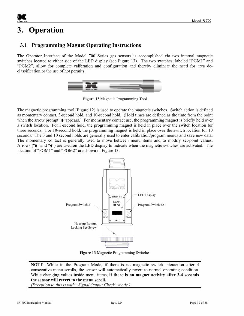
3.1 Programming Magnet Operating Instructions The Operator Interface of the Model 700 Series gas sensors is accomplished via two internal magnetic switches located to either side of the LED display (see Figure 13). The two switches, labeled “PGM1” and “PGM2”, allow for complete calibration and configuration and thereby eliminate the need for area de-classification or the use of hot permits.
Figure 12 Magnetic Programming Tool
Figure 12 The magnetic programming tool ( ) is used to operate the magnetic switches. Switch action is defined as momentary contact, 3-second hold, and 10-second hold. (Hold times are defined as the time from the point when the arrow prompt “ “appears.) For momentary contact use, the programming magnet is briefly held over a switch location. For 3-second hold, the programming magnet is held in place over the switch location for three seconds. For 10-second hold, the programming magnet is held in place over the switch location for 10 seconds. The 3 and 10 second holds are generally used to enter calibration/program menus and save new data. The momentary contact is generally used to move between menu items and to modify set-point values. Arrows (“ ” and “ ”) are used on the LED display to indicate when the magnetic switches are activated. The location of “PGM1” and “PGM2” are shown in . Figure 13
Figure 13 Magnetic Programming Switches
detcon inc.
detcon inc.
Program Switch #1
Housing BottomLocking Set-Screw
PGM1
ZERO
Program Switch #2
LED Display
PGM2
SPAN
MODELIR-700
LEL
NOTE: While in the Program Mode, if there is no magnetic switch interaction after 4 consecutive menu scrolls, the sensor will automatically revert to normal operating condition. While changing values inside menu items, if there is no magnet activity after 3-4 seconds the sensor will revert to the menu scroll. (Exception to this is with “Signal Output Check” mode.)
IR-700 Instruction Manual Rev. 2.0 Page 12 of 38

Model IR-700
3.2 Operator Interface The operating interface is menu-driven via the two magnetic program switches located under the target marks of the sensor housing. The two switches are referred to as “PGM1” and “PGM2”. The menu list consists of three major items that include sub-menus as indicated below. (Refer to the complete Software Flow Chart.) Normal Operation
Current Reading and Fault Status
Calibration Mode
AutoZero AutoSpan
Program Mode
View Sensor Status
Sensor Model Type Current Software Version Gas Type Range of Detection Serial ID address AutoSpan Level Days From Last AutoSpan Remaining Sensor Life Gas Factor Raw Active Counts Raw Reference Counts 4-20mA Output Input Voltage Supply Sensor Temperature
Set AutoSpan Level Set Gas Type & Range Set Gas Factor Set Serial ID Set Sensor Gain Signal Output Check Restore Default Settings
IR-700 Instruction Manual Rev. 2.0 Page 13 of 38
Model IR-700
Software Flowchart
dec
dec
Temp = XX C
mA Output = XX.XX
Ref Counts = XXXX
Voltage XX.X VDC
Sensor Life XXX%
Last Cal XX Days
Gas Factor = X.XX
Act Counts = XXXX
inc
PGM1/2 (M)PGM2 (10)
Defaults Restored
PGM2 (S)
PGM1/2 (3)PGM1 (S)
Restore DefaultsAuto Time-Out
##
Calibration Mode(Auto Span)
AutoSpan @ XX
Range XXX
Serial ID XX
Gas Type
Auto Time-Out
Version X.XX
View Sensor Status
Model Type
PGM1/2 (3)PGM1/2 (M)
incPGM1 (S)
PGM1/2 (3)
Auto Time-OutPGM1/2 (M)
Set Serial ID
PGM1/2 (3)
AutoTime-out
PGM2 (S)
PGM1/2 (3)PGM1/2 (M)
Set AutoSpan Level
##
PGM1 (3)PGM2 (3)
Normal OperationPGM1 (3)PGM2 (10)
Calibration Mode(Auto Zero)
inc - Increasedec - DecreaseX, XX, XXX - numeric values
(S) - Momentary Swipe(M) - Momentary hold of Magnet during text scroll until the ">" appears, then release(3) - 3 second hold from ">" prompt(10) - 10 second hold from ">" promptAuto Time-out - 5 seconds
PGM1 - Program Switch Location #1PGM2 - Program Switch Location #2
LEGEND:
Setting GainPGM1/2 (3)Simulation
Auto Time-OutSet Gas Factor
Auto Time-OutSignal Output Check
Auto Time-OutSet Sensor Gain
Auto Time-Out
PGM1 (S)
PGM1/2 (M)PGM1/2 (3)
PGM1/2 (3)
inc
PGM1/2 (3)
PGM2 (S)Type ##
Set Gas Type & Range
PGM1/2 (M)
dec
incdecPGM1 (S)
PGM1/2 (10)PGM1/2 (M)
PGM1/2 (3)
PGM1/2 (3)
PGM2 (S)##
PGM1/2 (M)
PGM1 (S)PGM1/2 (3)
inc PGM2 (S)Range ##
dec
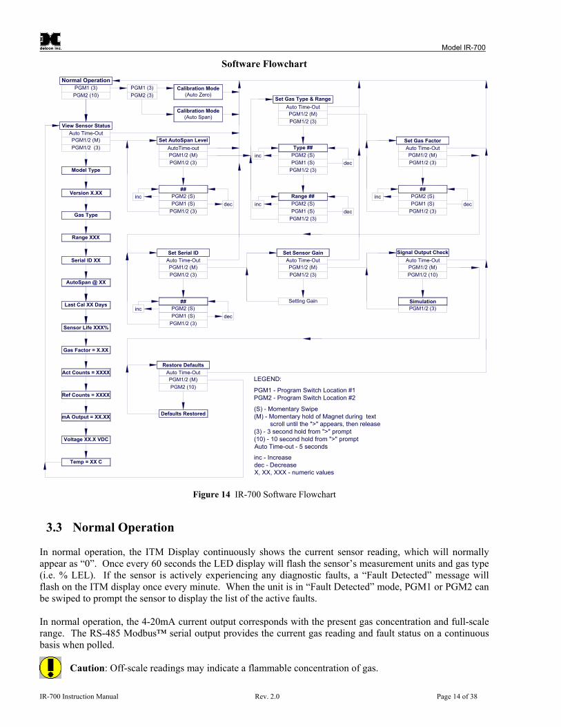
Figure 14 IR-700 Software Flowchart
3.3 Normal Operation In normal operation, the ITM Display continuously shows the current sensor reading, which will normally appear as “0”. Once every 60 seconds the LED display will flash the sensor’s measurement units and gas type (i.e. % LEL). If the sensor is actively experiencing any diagnostic faults, a “Fault Detected” message will flash on the ITM display once every minute. When the unit is in “Fault Detected” mode, PGM1 or PGM2 can be swiped to prompt the sensor to display the list of the active faults. In normal operation, the 4-20mA current output corresponds with the present gas concentration and full-scale range. The RS-485 Modbus™ serial output provides the current gas reading and fault status on a continuous basis when polled.
Caution: Off-scale readings may indicate a flammable concentration of gas.
IR-700 Instruction Manual Rev. 2.0 Page 14 of 38

Model IR-700
3.4 Calibration Mode (AutoZero and AutoSpan)
3.4.1 AutoZero The AutoZero function is used to set the sensor’s zero baseline. Local ambient air can be used to zero calibrate the sensor as long as it can be confirmed that it contains no combustible hydrocarbon gases. If this cannot be confirmed then a zero air or pure N2 cylinder should be used. The same AutoZero procedure applies for the CO2 version sensor. Material Requirements: -Detcon PN 327-000000-000 MicroSafe™ Programming Magnet -Detcon PN 613-120000-700 700 Series Splash Guard with integral Cal Port -OR-
-Detcon PN 943-000006-132 Threaded Calibration Adapter -Detcon PN 942-001123-000 Zero Air (or N2) cal gas, or use ambient air if no combustible gas is present. a) If the ambient air is known to contain no combustible hydrocarbon gas content, it can be used to calibrate
zero. If a zero air or N2 gas cal cylinder is going to be used then attach the calibration adapter and set flow rate of 200 cc/min and let sensor purge for 1-2 minutes before executing the AutoZero.
b) From Normal Operation, enter Calibration Mode by holding the programming magnet over PGM1 for 3
seconds. Note, the “ ” prompt will show that the magnetic switch is activated during the 3 second hold period. The display will then scroll “PGM1=Zero …PGM2=Span”. Hold the programming magnet over PGM1 for 3 seconds once the “ ” prompt appears to execute AutoZero (or allow to timeout in 5 seconds if AutoZero is not desired).
NOTE: Upon entering Calibration Mode, the 4-20mA signal drops to 2mA and is held at this level until the program returns to normal operation. Modbus™ Status Register bit 14 is also set to signify when the sensor is in-calibration mode.
c) The ITM will display the following sequence of text messages as it proceeds through the AutoZero
sequence: Zero Cal. . .Setting Zero. . . Zero Saved (each will scroll twice)
d) Remove the zero gas and calibration adapter, if applicable.
3.4.2 AutoSpan The AutoSpan function is used to span calibrate the sensor. Span adjustment is recommended at 50% LEL for combustible gas sensors and 50% of range for CO2 sensors. Follow the same procedure for both
NOTE: Before performing AutoSpan Calibration, verify that the AutoSpan level matches the span calibration gas concentration as described in Section 3.5.2 . Set AutoSpan Level
Material Requirements: -Detcon PN 327-000000-000 MicroSafe™ Programming Magnet -Detcon PN 613-120000-700 700 Series Splash Guard with integral Cal Port -OR-
-Detcon PN 943-000006-132 Threaded Calibration Adapter -Detcon PN 942-520124-050 50% LEL Methane in balance air (highly recommended) or other suitable span gas containing a certified level of % LEL concentration of common combustible hydrocarbon gas.
IR-700 Instruction Manual Rev. 2.0 Page 15 of 38

Model IR-700
NOTE: If the span gas is different from the measured target gas, remember to use the appropriate Gas Factor as described in Section 3.5.4.
CAUTION: Verification that the calibration gas level setting matches the calibration span gas concentration is required before executing “AutoSpan” calibration. These two numbers must be equal.
AutoSpan consists of entering Calibration Mode and following the menu-displayed instructions. The display will ask for the application of span gas in a specific concentration. This concentration must be equal to the calibration gas level setting. The factory default setting and recommendation for span gas concentration is 50% LEL. If a span gas containing the recommended concentration is not available, other concentrations may be used as long as they fall between 10% and 90% LEL. However, any alternate span gas concentration value must be programmed via the “Set AutoSpan Level” menu before proceeding with AutoSpan calibration. Follow the instructions “a” through “e” below for AutoSpan calibration. a) Verify that the AutoSpan Level is equal to the calibration span gas concentration. (Refer to View Sensor
Status in Section 3.5.1.) If the AutoSpan Level is not equal to the calibration span gas concentration, adjust the AutoSpan Level as instructed in Section 3.5.2 Set AutoSpan Level.
b) From Normal Operation, enter Calibration Mode by holding the programming magnet over PGM1 for 3
seconds. Note, the “ ” prompt will show that the magnetic switch is activated during the 3 second hold period. The display will then scroll “PGM1=Zero…PGM2=Span”. Hold the programming magnet over PGM2 for 3 seconds to execute AutoSpan (or allow to timeout in 5 seconds if AutoSpan is not intended). The ITM will then scroll “Apply XX %LEL Gas” (where XX is the AutoSpan Level).
NOTE: Upon entering Calibration Mode, the 4-20mA signal drops to 2mA and is held at this level until the program returns to normal operation. Modbus™ Status Register bit 14 is also set to signify when the sensor is in-calibration mode.
c) Apply the span calibration test gas at a flow rate of 200cc/min. As the sensor signal begins to increase the
display will switch to reporting a flashing “XX“reading as the ITM shows the sensor’s “as found” response to the span gas presented. If it fails to meet the minimum in-range signal change criteria within 2½ minutes, the display will report “Range Fault” twice and the ITM will return to normal operation, aborting the AutoSpan sequence. The ITM will continue to report a “Range Fault” and will not clear the fault until a successful AutoSpan is completed.
Assuming acceptable sensor signal change, after 1 minute the reading will auto-adjust to the programmed AutoSpan level. During the next 30 seconds, the AutoSpan sequence checks the sensor for acceptable reading stability. If the sensor fails the stability check, the reading is re-adjusted back to the AutoSpan level and the cycle repeats until the stability check is passed. Up to three additional 30-second stability check periods are allowed before the unit reports a “Stability Fault” twice and the ITM will return to normal operation, aborting the AutoSpan sequence. The ITM will continue to report a “Stability Fault” and will not clear the fault until a successful AutoSpan is completed. If the sensor passes the stability check, the ITM reports a series of messages: “AutoSpan Complete” “Sensor Life XXX%” “Remove Span Gas” d) Remove the span gas and calibration adapter. The ITM will report a live reading that alternates with
“Remove Gas” message as it clears toward “0”. When the reading clears below 5 % LEL, the ITM will display “Span Complete” and will revert to normal operation. If the sensor fails to clear to less than 5 % LEL in less than 5 minutes, a “Clearing Fault” will be reported twice and the ITM will return to normal
IR-700 Instruction Manual Rev. 2.0 Page 16 of 38

Model IR-700
operation, aborting the AutoSpan sequence. The ITM will continue to report a “Clearing Fault” and will not clear the fault until a successful AutoSpan is completed.
NOTE 1: If the sensor fails the minimum signal change criteria, a “Range Fault” will be declared and a “Fault Detected” message will be displayed alternately with the sensor’s current reading. The 4-20 output will be taken to 0mA and the “Range Fault” fault bit will be set on the Modbus output.
NOTE 2: If the sensor fails the stability criteria, a “Stability Fault” will be declared and a “Fault Detected” message will be displayed alternately with the sensor’s current reading. The 4-20mA output will be taken to 0mA and the “Stability Fault” fault bit will be set on the Modbus output.
NOTE 3: If the sensor fails the clearing time criteria, a “Clearing Fault” will be declared and a “Fault Detected” message will be displayed alternately with the sensor’s current reading. The 4-20 output will be taken to 0mA and the “Clearing Fault” fault bit will be set on the Modbus output.
3.5 Program Mode Program Mode provides a View Sensor Status menu to check operational and configuration parameters. Program Mode also provides for adjustment of the AutoSpan Level, Gas Factor, Gas Type and Range, and Serial ID. Additionally, it includes the Set Sensor Gain, Restore Factory Defaults, and Signal Output Check diagnostic functions. The Program Mode menu items appear in the order presented below:
View Sensor Status Set AutoSpan Level Set Gas Type and Range Set Gas Factor Set Serial ID Set Sensor Gain Signal Output Check Restore Defaults
Navigating Program Mode
From Normal Operation, enter Program Mode by holding the magnet over PGM2 for 10 seconds. Note, the “ ” prompt will show that the magnetic switch is activated during the 10 second hold period. The ITM will enter Program Mode and the display will scroll the first menu item “View Sensor Status”. To advance to the next menu item, hold the magnet over PGM1 or PGM2 while the current menu item’s text is scrolling. At the conclusion of the text scroll the “ ”prompt (“ ” for PGM2 or “ ” for PGM1) will appear, and immediately remove the magnet. The ITM will advance to the next menu item. Repeat this process until the desired menu item is displayed. Note, PGM1 moves the menu items from right to left and PGM2 moves the menu items from left to right. To enter a menu item, hold the magnet over PGM1 or PGM2 while the menu item is scrolling. At the conclusion of the text scroll the “ ”prompt (“ ” for PGM2 or “ ” for PGM1) will appear, continue to hold the magnet over PGM1 or PGM2 for an additional 3-4 seconds to enter the selected menu item. If there is no magnet activity while the menu item text is scrolling (typically 4 repeated text scrolls), the ITM will automatically revert to Normal Operation.
IR-700 Instruction Manual Rev. 2.0 Page 17 of 38
Model IR-700
3.5.1 View Sensor Status
View Sensor Status displays all current configuration and operational parameters including: sensor type, software version number, detection range, AutoSpan level, days since last AutoSpan, estimated remaining sensor life, gas factor, gas type, input voltage, 4-20 output, active counts, reference counts, and sensor ambient temperature. From the View Sensor Status text scroll, hold the magnet over PGM1 or PGM2 until the “ ” prompt appears and continue to hold the magnet in place for an additional 3-4 seconds (until the display starts to scroll “Status Is”). The display will scroll the complete list of sensor status parameters sequentially: Sensor Model Type
The menu item appears as: “Model IR-700” Current Software Version
The menu item appears as: “Version 1.XX” Gas Type
The menu item appears as: “Gas Type = CH4” Range of Detection
The menu item appears as: “Range XXX” Serial ID Address
The menu item appears as: “Serial ID XX” AutoSpan Level.
The menu item appears as: “Auto Span Level XX” Days From Last AutoSpan
The menu items appears as: “Last Cal XX days” Remaining Sensor Life
The menu item appears as: “Sensor Life 100%” Gas Factor
The menu item appears as: “Gas Factor = X.XX” Raw Active Counts
The menu item appears as: “Active Counts XXXX” Raw Reference Counts
The menu item appears as: “Reference Counts XXXX”
IR-700 Instruction Manual Rev. 2.0 Page 18 of 38

Model IR-700
4-20mA Output
The menu item appears as: “mA Output X.XXmA” Input Voltage Supply
The menu item appears as: “Voltage XX.X VDC” Sensor Operating Temperature
The menu item appears as: “Temp XX C” When the status list sequence is complete, the ITM will revert to the “View Sensor Status” text scroll. The user can either: 1) review list again by executing another 3-4 second hold, 2) move to another menu item by executing a momentary hold over PGM1 or PGM2, or 3) return to Normal Operation via automatic timeout of about 15 seconds (the display will scroll “View Sensor Status” 4 times and then return to Normal Operation).
3.5.2 Set AutoSpan Level Set AutoSpan Level is used to set the span gas concentration level that is being used to calibrate the sensor. This level is adjustable from 5% to 95% of range. The current setting can be viewed in View Program Status. The menu item appears as: “Set AutoSpan Level”. From the Set AutoSpan Level text scroll, hold the magnet over PGM1 or PGM2 until the “ ” prompt appears and continue to hold the magnet in place for an additional 3-4 seconds (until the display starts to scroll “Set Level”). The display will switch to “XX“(where XX is the current gas level). Swipe the magnet momentarily over PGM2 to increase or PGM1 to decrease the AutoSpan Level until the correct level is displayed. When the correct level is achieved, hold the magnet over PGM1 or PGM2 for 3-4 seconds to accept the new value. The display will scroll “Level Saved”, and revert to “Set AutoSpan Level” text scroll. Move to another menu item by executing a momentary hold, or return to Normal Operation via automatic timeout of about 15 seconds (the display will scroll “Set AutoSpan Level” 4 times and then return to Normal Operation).
3.5.3 Set Gas Type & Range The IR sensor has a slightly different linearization requirement for different groupings of target gases. The four groupings are 1) Methane (CH4) and 2) Heavier Hydrocarbons (H HC) and 3) % by volume (%VOL) and 4) CO2. The Set Gas Type menu function is a simple choice between these four gas type groupings.
NOTE: The default value for Gas Type is methane (CH4). The menu item appears as: “Set Gas Type”. From the Set Gas Type & Range text scroll, hold the magnet over PGM1 or PGM2 until the “ ” prompt appears and continue to hold the magnet in place for an additional 3-4 seconds (until the display starts to scroll “CH4 / H HC / %VOL / CO2”). Swipe the magnet momentarily over PGM2 or PGM1 to change the selection until the correct choice is displayed. Hold the magnet over PGM1 or PGM2 for 3 seconds to accept the new value. The display will scroll “Type Saved”, then “Set Range” followed by the currently selected Range. Momentarily hold the magnet over PGM1 or PGM2 to change the Range Selection until the correct value is displayed. Hold the magnet over PGM1 or PGM2 for 3 seconds to accept the new value.
IR-700 Instruction Manual Rev. 2.0 Page 19 of 38

Model IR-700
NOTE 1: If a gas type of CH4 or HHC or %VOL is selected the range can only be set to 100. If CO2 gas type is selected range selections are 0.3, 0.5, 1, 3, 5, 10, 15, 20, 25, 50, and 100.
NOTE 2: For CO2 there are two different plug-in IR sensors. One sensor is used for the ranges of 0.3, 0.5, 1, 3, and 5. The second is used for the rages of 10, 15, 20, 25, 50, and 100. These sensors cannot be mismatched.
Move to another menu item by executing a momentary hold, or, return to Normal Operation via automatic timeout of about 15 seconds (the display will scroll “Set Gas Type and Range” 4 times and then return to Normal Operation).
3.5.4 Set Gas Factor Because of the IR sensor’s almost universal response to combustible hydrocarbon gases, the IR-700 sensor can be configured and calibrated to detect any of the combustible gases listed in the Table 2 and others not shown. The detected gas is referred to as the “target gas” and the span calibration gas is referred to as the “cal gas”. In cases where the cal gas is different from the target gas, the Set Gas Factor menu function is used to maintain accuracy. This feature allows for a significant degree of flexibility in the detection and span calibration process.
NOTE 1: The default value for Gas Factor is 1.0. This would be used when the target gas is the same as the cal gas. Values other than 1.0 would be used when the target gas is different from the cal gas.
NOTE 2: The “Set Gas Factor” is not applicable for CO2 versions and should be set to 1.0
Set Gas Factor is used to make the appropriate signal sensitivity adjustment when the target gas is different from the cal gas. This is necessary because the IR sensor has different signal strengths for each combustible hydrocarbon gas. The Gas Factor value is adjustable from 0.2 to 5.0. It represents the translation between the target gas and the cal gas when they are different. To calculate the correct Gas Factor, refer to Table 2 and take the Gas Factor of the target gas and divide by the Gas Factor of the cal gas. The calculated value is the correct number to enter into the menu as the Gas Factor. For example, if calibrating with methane when propane is the target gas, the correct Gas Factor to enter would be 0.63/1.0 = 0.63. For example, if calibrating with butane when ethane is the target gas, the correct Gas Factor to enter would be 0.38/0.72=0.53. Table 2 shows the Gas Factors of most combustible hydrocarbon gases that will be measured. Find the gas of interest for the cal gas and the target gas and follow the above instruction. If there is a mixture of target gases, use a weighted approach to determine the correct Gas Factor. For example, if the target gas was 50% butane and 50% pentane and the cal gas was methane, the correct Gas Factor would be calculated and entered as ((0.5 x 0.77) + (0.5 x 0.77)) / 1.0 = 0.77.
IR-700 Instruction Manual Rev. 2.0 Page 20 of 38

Model IR-700
Table 2 Gas Factors Gas Factor Gas Factor Gas Factor
Acetic Acid 2.00 Decane 1.53 Naphthalene Acetone 1.21 Ethyl Alcohol 0.35 n-Nonane 1.53 Benzene 1.00 Ethane 0.38 n-Octane 1.34 1,3-Butadiene 1.80 Ethyl Benzene 1.07 n-Pentane 0.77 Butane 0.77 Ethylene 2.39 Propane 0.63 Iso-Butane 0.72 n-Heptane 0.98 iso-Propyl Alcohol 0.54 Butene-1 0.67 n-Hexane 1.00 Propylene 0.80 n-Butyl Alcohol 0.63 Dimethyl Ether 0.40 Toluene 1.00 iso-Butyl Alcohol 0.63 Methane 1.00 Vinyl Acetate 1.43 Cyclohexane 0.89 Methanol 0.41 Vinyl Chloride Cyclopropane 0.45 Methyl Ethyl Ketone 0.77 Xylene 1.00
The menu item appears as: “Set Gas Factor”. From the Set Gas Factor text scroll, hold the magnet over PGM1 or PGM2 until the “ ” prompt appears and continue to hold the magnet in place for an additional 3-4 seconds (until the display starts to scroll “Set Factor”). The display will then switch to “X.XX“(where X.XX is the current gas factor). Swipe the magnet momentarily over PGM2 to increase or PGM1 to decrease the gas factor level until the correct value is displayed. Hold the magnet over PGM1 or PGM2 for 3 seconds to accept the new value. The display will scroll “Factor Saved”, and revert to “Set Gas Factor” text scroll. Move to another menu item by executing a momentary hold, or, return to Normal Operation via automatic timeout of about 15 seconds (the display will scroll “Set Gas Factor” 4 times and then return to Normal Operation).
3.5.5 Set Serial ID Detcon Model IR-700 sensors can be polled serially via RS-485 Modbus™ RTU. Refer to Section 4.0 for details on using the Modbus output feature. Set Serial ID is used to set the Modbus serial ID address. It is adjustable from 01 to 256 in hexadecimal format (01-FF hex). The current serial ID can be viewed in View Sensor Status using the instruction given in Section 3.5.1 View Sensor Status. The menu item appears as: “Set Serial ID”. From the “Set Serial ID” text scroll, hold the programming magnet over PGM1 or PGM2 until the “ ” prompt appears and continue to hold the magnet in place for an additional 3-4 seconds (until the display starts to scroll “Set ID”). The display will then switch to “XX“(where XX is the current ID address). Swipe the magnet momentarily over PGM2 to increase or PGM1 to decrease the hexadecimal number until the desired ID is displayed. Hold the magnet over PGM1 or PGM2 for 3-4 seconds to accept the new value. The display will scroll “ID Saved”, and revert to “Set Serial ID” text scroll. Move to another menu item by executing a momentary hold, or, return to Normal Operation via automatic timeout of about 15 seconds (the display will scroll “Set Serial ID” 5 times and then return to Normal Operation).
3.5.6 Set Sensor Gain Each Detcon IR-700 combustible hydrocarbon gas sensor requires a one-time gain setting to match the plug-in IR sensor with the ITM electronics. This is set automatically during the “Set Sensor Gain” sequence. The
IR-700 Instruction Manual Rev. 2.0 Page 21 of 38

Model IR-700
“Set Sensor Gain” sequence determines the required gain resistance setting for optimal operation. This technique provides for uniformity in sensor-to-sensor operational performance.
NOTE: The “Set Sensor Gain” function is executed during factory calibration of every IR-700 sensor. In the field, this menu item is only needed when a replacement plug-in IR sensor is being installed, or when mating a new IR-700 ITM with an existing plug-in sensor. It is also required if the Restore Defaults menu item is executed.
The menu item appears as: “Set Sensor Gain”. From the Set Sensor Gain text scroll, hold the magnet over PGM1 or PGM2 until the “ ” prompt appears and then hold continuously for an additional 3 seconds. The display will scroll “Setting Gain” and then show the count-up of the gain settings for the active and reference detectors. The typical final values are A = 9 and R = 37. At conclusion, the ITM will display “Gain Complete” and revert to “Set Sensor Gain” text scroll. The user can then choose to either: 1) move to another menu item by executing a momentary hold, or 2) return to Normal Operation via 5 second automatic timeout.
3.5.7 Signal Output Check Signal Output Check provides a simulated 4-20mA output and RS-485 Modbus™ output. This simulation allows the user to conveniently perform a functional system check of their entire safety system. This signal output simulation also aids the user in performing troubleshooting of signal wiring problems. The menu item appears as: “Signal Output Check”. From the “Signal Output Check” text scroll, hold the magnet over PGM1 or PGM2 until the “ ” prompt appears and then hold continuously for an additional 10 seconds. Once initiated, the display will scroll “Simulation Active” until the function is stopped. During simulation mode, the 4-20mA value will be increased from 4.0mA to 20.0mA (in 1% of range increments at about a 1 second update rate) and then decreased from 20.0mA to 4.0mA. The same simulation sequence is applied to the Modbus™ output gas reading.
NOTE: Signal Output Check stays active indefinitely until the user stops the function. There is no automatic timeout for this feature.
To end simulation mode, hold magnet over PGM1 or PGM2 for 3 seconds. The display will either move to the prior menu item or move to the next menu item respectively. Move to another menu item by executing a momentary hold, or, return to Normal Operation via automatic timeout of about 15 seconds.
3.5.8 Restore Factory Defaults Restore Factory Defaults is used to clear current user configuration and calibration data from memory and revert to factory default values. This may be required if the settings have been configured improperly and a known reference point needs to be re-established to correct the problem. This menu item appears as: “Restore Defaults”.
NOTE: “Restoring Factory Defaults” should only be used when absolutely necessary. All previously existing configurational inputs will have to be re-entered if this function is executed. A full 10-second magnet hold on PGM 2 is required to execute this function.
IR-700 Instruction Manual Rev. 2.0 Page 22 of 38

Model IR-700
From the “Restore Defaults” text scroll, hold the programming magnet over PGM2 until the “ ” prompt appears and continue to hold 10 seconds. The display will scroll “Restoring Defaults”, and then will revert to the “Restore Defaults” text scroll. Move to another menu item by executing a momentary hold, or, return to Normal Operation via automatic timeout of about 15 seconds (the display will scroll “Restore Defaults” 4 times and then return to Normal Operation). Following the execution of “Restore Defaults”, the IR-700 will revert to its factory default settings. The default settings are:
Serial ID = 01. The Serial ID must be set appropriately by the operator (Section 3.5.5).
NOTE: The following must be performed in order before the sensor can be placed in operation.
AutoSpan Level = 50 %LEL. AutoSpan level must be set appropriately by the operator (Section 3.5.2). Gas Type = CH4. The Gas Type must be set appropriately by the operator (Section 3.5.3). Gas Factor = 1.0. The Cal Factor must be set appropriately by the operator (Section 3.5.4). Sensor Gain: Sensor gain settings are lost. Sensor Gain must be performed (Section 3.5.6). AutoZero: AutoZero Calibration Settings are lost. AutoZero must be performed (Section 3.4). AutoSpan: AutoSpan Calibration Settings are lost. AutoSpan must be performed (Section 3.4).
3.6 Program Features Detcon IR-700 gas sensors incorporate a comprehensive set of diagnostic features to achieve Fail-Safe Operation. These Operational features and Failsafe Diagnostic features are detailed below.
3.6.1 Operational Features Over-Range
When gas greater than the full-scale range is detected, the ITM display will continuously flash the full-scale reading of 100. This designates an over-range condition. The 4-20mA signal will report a 22mA output during this time. Negative Drift
In cases where the sensor may drift negative, the display will show a negative reading between 5% and 10% of the sensors full scale range. I.E., if a 0-100ppm sensor drifts to negative 6 the display will indicate -6. In cases where the full scale range of the sensor is less than 10ppm, due to the limited space on the display, the decimal point will be displayed as an asterisk (*) to denote a negative reading. I.E., if a 0-5ppm sensor drifts to negative 0.32 the display will show 0*32. In-Calibration Status
When the sensor is engaged in AutoZero or AutoSpan calibration, the 4-20mA output signal is taken to 2.0mA and the in-calibration Modbus™ Status Register bit 14 is set. This alerts the user that the ITM is not in an active measurement mode. This feature also allows the user to log the AutoZero and AutoSpan events via their master control system.
IR-700 Instruction Manual Rev. 2.0 Page 23 of 38

Model IR-700
Sensor Life
Sensor Life is calculated after each AutoSpan calibration and is reported as an indicator of remaining service life. It is reported in the “View Sensor Status” menu and as a RS-485 Modbus register bit. Sensor Life is reported on a scale of 0-100%. When Sensor Life falls below 25%, the sensor cell should be replaced within a reasonable maintenance schedule. Last AutoSpan Date
This reports the number of days that have elapsed since the last successful AutoSpan. This is reported in the View Sensor Status menu.
3.6.2 Fault Diagnostic/Fail-Safe Features Fail-Safe/Fault Supervision
Model IR-700 MicroSafe™ sensors are designed for Fail-Safe operation. If any of the diagnostic faults listed below are active, the ITM Display will scroll the message “Fault Detected” every 30 seconds during normal operation. At any time while the “Fault Detected” message is active, swipe the magnet over PGM1 or PGM2 to display the active fault(s). All active faults will then be reported sequentially. Most fault conditions result in failed operation of the sensor and in those cases the 4-20mA signal is dropped to the universal fault level of 0mA. These include Zero Fault, AutoSpan Calibration Faults, Sensor Fault, Processor Fault, Memory Fault, Loop Fault, and Input Voltage Fault. The 0mA fault level is not employed for a Temperature Fault and AutoSpan Reminder Fault. For all diagnostic faults, the associated RS-485 Modbus™ fault register will be flagged to alert the user digitally.
NOTE 1: Refer to the Troubleshooting Guide section 6 for guidance on fault conditions.
NOTE 2: The 0mA fault level is not employed for a Temperature Fault and AutoSpan Reminder Fault.
Zero Fault
If the sensor drifts below –10% LEL, the “Zero Fault” will be declared. A “Zero Fault” will cause a “Fault Detected” message to scroll once a minute on the ITM display and drop the 4-20mA output to 0mA. The Modbus™ fault register bit for Zero Fault will be set and will not clear until the fault condition has been cleared. The sensor should be considered “Out-of-Service” until a successful AutoZero calibration is performed. Range Fault – AutoSpan
If the sensor fails the minimum signal change criteria during AutoSpan sequence (Section 3.4.2) the “Range Fault” will be declared. A “Range Fault” will cause a “Fault Detected” message to scroll once a minute on the ITM display and drop the 4-20mA output to 0mA. The Modbus™ fault register bit for Range Fault will be set and will not clear until the fault condition has been cleared. The sensor should be considered “Out-of-Service” until a successful AutoSpan calibration is performed. Stability Fault - AutoSpan
If the sensor fails the signal stability criteria during AutoSpan sequence (Section 3.4.2) the “Stability Fault” will be declared. A “Stability Fault” will cause a “Fault Detected” message to scroll once a minute on the ITM display and drop the milliamp output to 0mA. The Modbus™ fault register bit for Stability Fault will be set and will not clear until the fault condition has been cleared. The sensor should be considered as “Out-of-Service” until a successful AutoSpan calibration is performed.
IR-700 Instruction Manual Rev. 2.0 Page 24 of 38

Model IR-700
Clearing Fault - AutoSpan
If the sensor fails the signal stability criteria during AutoSpan sequence (Section 3.4.2) the “Clearing Fault” will be declared. A “Clearing Fault” will cause a “Fault Detected” message to scroll once a minute on the ITM display and drop the milliamp output to 0mA. The Modbus™ fault register bit for Clearing Fault will be set and will not clear until the fault condition has been cleared. The sensor should be considered as “Out-of-Service” until a successful AutoSpan calibration is performed. Sensor Fault
If the plug-in IR sensor, or the supporting electronics, fails to meet the required minimum or maximum working signal parameters a “Sensor Fault” will be declared. A “Sensor Fault” will cause a “Fault Detected” message to scroll once a minute on the ITM display. The Modbus™ fault register bit for Sensor Fault will be set and will not clear until the fault condition has been cleared. If a Sensor Fault occurs, the 4-20mA signal will be set at 0mA until the fault condition is resolved. Processor Fault
If the detector has any unrecoverable run-time errors, a “Processor Fault” is declared. A “Processor Fault” will cause a “Fault Detected” message to scroll once a minute on the ITM display. The Modbus™ fault register bit for Processor Fault will be set and will not clear until the fault condition has been cleared. If a Processor Fault occurs, the 4-20mA signal will be set at 0mA until the fault condition is resolved. Memory Fault
If the detector has a failure in saving new data to memory, a “Memory Fault” is declared. A “Memory Fault” will cause the “Fault Detected” message to scroll once a minute on the ITM display. The Modbus™ fault register bit for Memory Fault will be set and will not clear until the fault condition has been cleared. If a Memory Fault occurs, the 4-20mA signal will be set at 0mA until the fault condition is resolved. 4-20mA Loop Fault
If the sensor detects a condition where the 4-20mA output loop is not functional (high loop resistance or failed circuit function) a “4-20mA Fault” is declared. A “4-20mA Fault” will cause the “Fault Detected” message to scroll once a minute on the ITM display. The Modbus™ fault register bit for Loop Fault will be set and will not clear until the fault condition has been cleared. If a Loop Fault occurs, the 4-20mA signal will be set at 0mA until the fault condition is resolved. Input Voltage Fault
If the detector is currently receiving an input voltage that is outside of the 11.5-28 VDC range, an “Input Voltage Fault” is declared. An “Input Voltage Fault” will cause the “Fault Detected” message to scroll once a minute on the ITM display. The fault register bit for Input Voltage Fault will be set and will not clear until the fault condition has been cleared. If an Input Voltage Fault occurs, the 4-20mA signal will be set at 0mA until the fault condition is resolved. Temperature Fault
If the detector is currently reporting an ambient temperature that is outside of the –40C to +75C range a “Temperature Fault” is declared. A “Temperature Fault” will cause the “Fault Detected” message to scroll once a minute on the ITM display. The Modbus™ fault register bit for Temperature Fault will be set and will not clear until the fault condition has been cleared. If a Temperature Fault occurs, the 4-20mA signal remains operational.
IR-700 Instruction Manual Rev. 2.0 Page 25 of 38

Model IR-700
AutoSpan Reminder Fault
If 180 days has elapsed since the last successful AutoSpan, an AutoSpan Fault will be generated. An “AutoSpan Fault” will cause the “Fault Detected” message to scroll once a minute on the ITM display. The Modbus™ fault register bit for AutoSpan Reminder Fault will be set and will not clear until the fault condition has been cleared. If an AutoSpan Reminder Fault occurs, the 4-20mA signal remains operational.
IR-700 Instruction Manual Rev. 2.0 Page 26 of 38

Model IR-700
4. RS-485 Modbus™ Protocol Model IR-700 sensors feature Modbus™ compatible communications protocol and are addressable via the program mode. Other protocols are available. Contact the Detcon factory for specific protocol requirements. Communication is two wire, half duplex 485, 9600 baud, 8 data bits, 1 stop bit, no parity, with the sensor set up as a slave device. A master controller up to 4000 feet away can theoretically poll up to 256 different sensors. This number may not be realistic in harsh environments where noise and/or wiring conditions would make it impractical to place so many devices on the same pair of wires. If a multi-point system is being utilized, each sensor should be set for a different address. Typical address settings are: 01, 02, 03, 04, 05, 06, 07, 08, 09, 0A, 0B, 0C, 0D, 0E, 0F, 10, 11…etc. Sensor RS-485 ID numbers are factory default to 01. These can be changed in the field via the Operator Interface described in Section 3.5.5 Set Serial ID. The following section explains the details of the Modbus™ protocol that the IR-700 sensor supports. Code 03 - Read Holding Registers is the only code supported by the transmitter. Each transmitter contains 6 holding registers which reflect its current status. Register # High Byte Low Byte 40000 Gas type Gas type is one of the following: 01=CO, 02=H2S, 03=SO2, 04=H2, 05=HCN, 06=CL2, 07=NO2, 08=NO, 09=HCL, 10=NH3, 11=LEL, 12=O2 Register # High Byte Low Byte 40001 Detectable Range i.e. 100 for 0-100 ppm, 50 for 0-50% LEL, etc. Register # High Byte Low Byte 40002 Current Gas Reading The current gas reading as a whole number; if the reading is displayed as 23.5 on the display, this register would contain the number 235. Register # High Byte Low Byte 40003 Auto Span Level Register # High Byte Low Byte 40004 Sensor Life Sensor life is an estimated remaining use of the sensor head, between 0% and 100%. Example: 85=85% sensor life Register # High Byte Low Byte 40005 Status Bits Status Bits Bits read as 0 are FALSE; bits read as 1 are TRUE
IR-700 Instruction Manual Rev. 2.0 Page 27 of 38

Model IR-700
Status Bits High Byte: Bit 15 – Reserved Bit 14 – Calibration Mode Bit 13 – Reserved Bit 12 – Zero Fault Bit 11 – Range Fault Bit 10 – Stability Fault Bit 9 – Clearing Fault Bit 8 – Reserved Status Bits Low Byte: Bit 7 – Sensor Fault Bit 6 – Processor Fault Bit 5 – Memory Fault Bit 4 – Input Voltage Fault Bit 3 – 4-20ma Fault Bit 2 – Temperature Fault Bit 1 – Auto Span Fault Bit 0 – Global Fault
IR-700 Instruction Manual Rev. 2.0 Page 28 of 38
Model IR-700
5. Service and Maintenance Calibration Frequency
In most applications, quarterly to biannual zero and semi-annual to annual span calibration intervals will assure reliable detection. However, industrial environments differ. Upon initial installation and commissioning, close frequency tests should be performed, weekly to monthly. Test results should be recorded and reviewed to determine a suitable calibration interval. Visual Inspection
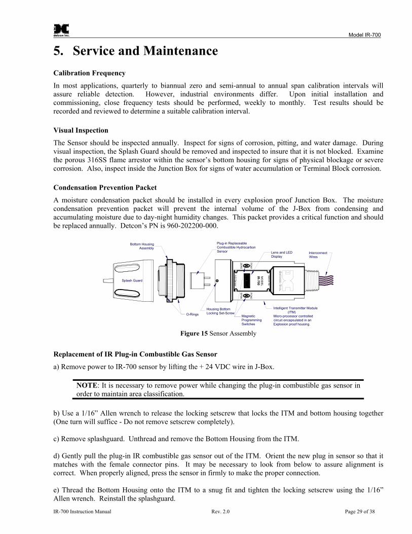
The Sensor should be inspected annually. Inspect for signs of corrosion, pitting, and water damage. During visual inspection, the Splash Guard should be removed and inspected to insure that it is not blocked. Examine the porous 316SS flame arrestor within the sensor’s bottom housing for signs of physical blockage or severe corrosion. Also, inspect inside the Junction Box for signs of water accumulation or Terminal Block corrosion. Condensation Prevention Packet
A moisture condensation packet should be installed in every explosion proof Junction Box. The moisture condensation prevention packet will prevent the internal volume of the J-Box from condensing and accumulating moisture due to day-night humidity changes. This packet provides a critical function and should be replaced annually. Detcon’s PN is 960-202200-000.
O-Rings
Bottom HousingAssembly
SPA
N
PG
M2
ZER
O
PG
M1
de
tcon
inc.
Plug-in ReplaceableCombustible HydrocarbonSensor Lens and LED
DisplayInterconnectWires
Housing BottomLocking Set-Screw
Intelligent Transmitter Module (ITM)Micro-processor controlledcircuit encapsulated in anExplosion proof housing.
MagneticProgrammingSwitches
Splash Guard
MO
DE
LIR
-700
detcon inc.
H2S
Sensor
Figure 15 Sensor Assembly
Replacement of IR Plug-in Combustible Gas Sensor
a) Remove power to IR-700 sensor by lifting the + 24 VDC wire in J-Box.
NOTE: It is necessary to remove power while changing the plug-in combustible gas sensor in order to maintain area classification.
b) Use a 1/16” Allen wrench to release the locking setscrew that locks the ITM and bottom housing together (One turn will suffice - Do not remove setscrew completely). c) Remove splashguard. Unthread and remove the Bottom Housing from the ITM. d) Gently pull the plug-in IR combustible gas sensor out of the ITM. Orient the new plug in sensor so that it matches with the female connector pins. It may be necessary to look from below to assure alignment is correct. When properly aligned, press the sensor in firmly to make the proper connection. e) Thread the Bottom Housing onto the ITM to a snug fit and tighten the locking setscrew using the 1/16” Allen wrench. Reinstall the splashguard.
IR-700 Instruction Manual Rev. 2.0 Page 29 of 38

Model IR-700
f) With the new IR plug-in sensor physically installed, two functions are required to be performed: 1) Perform the Set Sensor Gain function to match the new sensor with the ITM (Section 3.5.6). 2) Perform a successful AutoZero and AutoSpan to match the new sensor with the ITM (Section 3.4). Replacement of ITM
a) Disconnect all sensor wire connections at the J-Box after removing power source.
NOTE: It is necessary to remove power to the J-Box while changing the ITM in order to maintain area classification.
b) Use wrench and the wrench flats provided at the top section of the ITM and unthread until it can be removed. c) Use a 1/16” Allen wrench to release the locking setscrew that locks the ITM and bottom housing together (One turn will suffice - Do not remove setscrew completely). d) Remove splashguard. Unthread and remove the Bottom Housing from the ITM. e) Gently pull the plug-in IR combustible gas sensor out of the ITM and set it aside along with the bottom housing and splashguard. Orient the plug in sensor so that it matches with the female connector pins on the new ITM and press the sensor in firmly to make proper connection. f) Thread the bottom housing onto the ITM until snug, tighten the locking setscrew and reconnect splashguard. g) Feed the sensor assembly wires through the ¾” female NPT mounting hole and thread the assembly into the J-box until tight and the ITM lens faces toward the front access point. Connect the sensor assembly wires inside J-Box (Refer to Section 2.6, and ). Figure 11 h) Two functions are required to be performed on the new ITM: 1) Perform the Set Sensor Gain function to match the new sensor with the ITM (Section 3.5.6). 2) Perform a successful AutoZero and AutoSpan to match the new sensor with the ITM (Section 3.4). Replacement of IR-700 Sensor Assembly
a) Disconnect all sensor wire connections at the J-Box, after removing power source.
NOTE: It is necessary to remove power to the J-Box while changing the IR-700 sensor in order to maintain area classification.
b) Use wrench and the wrench flats provided at the top section of the sensor and unthread until it can be removed. c) Feed the new IR-700 sensor assembly wires through the ¾” female NPT mounting hole and thread the assembly into the J-box until tight and the ITM lens faces toward the front access point. Connect the sensor assembly wires inside J-Box (Refer to Section 2.6, and Figure 11). d) IR-700 sensors are factory calibrated. However, they will require an initial AutoZero and AutoSpan (Section 3.4). They must also be configured per customer specific application requirements.
IR-700 Instruction Manual Rev. 2.0 Page 30 of 38

Model IR-700
6. Troubleshooting Guide Refer to the list of Failsafe Diagnostic features listed in Section 3.6.2 for additional reference in troubleshooting activities. Listed below are some typical trouble conditions and their probable cause and resolution path. Zero Fault
Probable Cause: Sensor Zero has drifted to <-10% LEL. Redo AutoZero. Replace the plug-in IR sensor if problem persists. Sensor Fault
Probable Causes: Plug-in sensor has failed. Recycle power to see if fault clears. Check “View Sensor Status” for a report of Active and Reference Counts (active and reference counts should be about 3000 with no gas applied). Perform Set Sensor Gain and note count values for Ag and Rg (Ag should be 7-11 and Rg should be 33-43). Replace the plug-in IR sensor. If problem persists with new plug-in sensor, replace ITM. AutoSpan Calibration Faults – (Range, Stability, and Clearing)
To clear any AutoSpan Calibration fault, the AutoSpan process must be completed successfully. Range Fault
Probable Causes: Cal Gas not applied or not applied at appropriate time, Failed Sensor, Problems w/ cal gas and delivery Perform AutoSpan following the instructions explicitly. Check that cal gas value matches the AutoSpan level. Verify correct Gas Type and Gas Factor is entered. Check validity of span gas and flow rate (check MFG date on cal cylinder). Check for obstructions through stainless steel sinter element (including being wet). Replace the plug-in IR sensor, and/or bottom housing. Stability Fault
Probable Causes: Failed Sensor, empty or close to empty Cal Gas Cylinder or problems with cal gas and delivery Perform AutoSpan following the instructions explicitly. Check that cal gas value matches the AutoSpan level. Verify correct Gas Type and Gas Factor is entered. Check validity of span gas and flow rate (check MFG date on cal cylinder). Check for obstructions through stainless steel sinter element (including being wet). Replace the plug-in IR sensor, and/or bottom housing. Clearing Fault
Probable Causes: Failed Sensor, Cal Gas not removed at appropriate time, problems with cal gas and delivery, or Background combustible gases preventing clearing Perform AutoSpan following the instructions explicitly. Remove calibration adapter and gas connections. Confirm no combustible gasses in background. IR-700 Instruction Manual Rev. 2.0 Page 31 of 38

Model IR-700
Check validity of span gas and flow rate (check MFG date on cal cylinder). Check for obstructions through stainless steel sinter element (including being wet). Replace the plug-in IR sensor, and/or bottom housing. Poor Calibration Repeatability
Probable Causes: Failed Sensor, use of wrong Cal Gas, problems w/ cal gas and delivery, Sensor Corrosion Check for adequate Sensor Life. Increase calibration frequency to quarterly. Verify correct Gas Type and Gas Factor is entered. Check validity of span gas and flow rate (check MFG date on cal cylinder). Check for obstructions through stainless steel sinter element (including being wet). Replace the plug-in IR sensor, and/or bottom housing. Unstable Output/ Sudden spiking
Possible Causes: Unstable power supply, inadequate grounding, or inadequate RFI protection Verify Power source is stable. Verify field wiring is properly shielded and grounded. Contact Detcon to optimize shielding and grounding. Add Detcon’s RFI Protection Circuit accessory. Nuisance Alarms
Check condulet for accumulated water and abnormal corrosion on terminal blocks. If nuisance alarms are happening at night, suspect condensation in condulet. Add or replace Detcon’s Condensation Prevention Packet P/N 960-202200-000. Investigate presence of other combustible hydrocarbon gases that may be causing sensor response. Processor and/or Memory Faults
Recycle power in attempt to clear problem Restore Factory Defaults - This will clear the processor’s memory and may correct problem. Remember to re-enter all customer settings for cal gas level, set gain, Serial ID after Restore Factory Defaults. If problem persists, replace the Intelligent Transmitter Module. Unreadable Display
If due to excessive sunlight, install a sunshade to reduce glare. Nothing Displayed – Transmitter not Responding
Verify condulet has no accumulated water or abnormal corrosion. Verify required DC power is applied to correct terminals. Swap with a known-good ITM to determine if ITM is faulty. Faulty 4-20mA Output
If unit has the 4-20mA Loop Fault displayed… Check that wiring is properly connected at terminal blocks and through to controller inputs. The 4-20 output loop must be closed (resistance of < 1000 ohms) to avoid the Loop Fault. Perform a “Signal Output Check” sequence via Section 3.5.7 and verify 4-20mA output with Current Meter. Swap with new ITM to determine if the ITM’s 4-20mA output circuit has failed. IR-700 Instruction Manual Rev. 2.0 Page 32 of 38

Model IR-700
No Communication - RS-485 Modbus™
If unit has a normal reading with no Faults displayed and the Modbus™ is not communicating…. Verify that the correct (and non-duplicated) serial address is entered (per Section 3.5.5). Check that wiring is properly connected at terminal blocks and through to controller inputs. Perform a “Signal Output Check” sequence via Section 3.5.7 and troubleshoot wiring. Swap with new ITM to determine if the ITM’s serial output circuit is faulty.
IR-700 Instruction Manual Rev. 2.0 Page 33 of 38

Model IR-700
7. Customer Support and Service Policy Detcon Headquarters Shipping Address: 3200 A-1 Research Forest Dr., The Woodlands Texas 77381 Mailing Address: P.O. Box 8067, The Woodlands Texas 77387-8067 Phone: 888.367.4286, or 281.367.4100 Fax: 281.292.2860 • www.detcon.com • [email protected] • [email protected] All Technical Service and Repair activities should be handled by the Detcon Service Department via phone, fax, or email at contact information given above. RMA numbers should be obtained from the Detcon Service Department prior to equipment being returned. For on-line technical service help, customers should have the model number/ part number, and serial number of product type in question. All Sales activities (including spare parts purchase) should be handled by the Detcon Sales Department via phone, fax, or email at contact information given above. Warranty Notice Detcon Inc. warrants the Model IR-700 gas sensor to be free from defects in workmanship of material under normal use and service for two years from the date of shipment on the ITM electronics and for a 5-year period on the plug-in IR combustible gas sensor and the IR CO2 gas sensor. See Warranty details below. Detcon Inc. will repair or replace without charge any such equipment found to be defective during the warranty period. Full determination of the nature of, and responsibility for, defective or damaged equipment will be made by Detcon Inc. personnel. Defective or damaged equipment must be shipped to the Detcon Inc. factory or representative from which the original shipment was made. In all cases, this warranty is limited to the cost of the equipment supplied by Detcon Inc. The customer will assume all liability for the misuse of this equipment by its employees or other contracted personnel. All warranties are contingent upon the proper use in the application for which the product was intended and does not cover products which have been modified or repaired without Detcon Inc. approval, or which have been subjected to neglect, accident, improper installation or application, or on which the original identification marks have been removed or altered. Except for the express warranty stated above, Detcon Inc. disclaims all warranties with regard to the products sold. Including all implied warranties of merchantability and fitness and the express warranties stated herein are in lieu of all obligations or liabilities on the part of Detcon Inc. for damages including, but not limited to, consequential damages arising out of, or in connection with, the performance of the product.
IR-700 Instruction Manual Rev. 2.0 Page 34 of 38

Model IR-700
8. IR-700 Sensor Warranty Plug-in IR Combustible Gas Sensor Warranty Detcon Inc. warrants, under normal intended use, each new plug-in IR combustible gas sensor (PN 370-3658CH-700 for combustible, P/N 370-865878-700 for ≤5% CO2, and P/N 370-287724-700 for ≥10% CO2.) for a five year period under the conditions described as follows: The warranty period begins on the date of shipment to the original purchaser and ends 5 years thereafter. The sensor element is warranted to be free of defects in material and workmanship. Should any sensor fail to perform in accordance with published specifications within the warranty period, return the defective part to Detcon, Inc., 3200 A-1 Research Forest Dr., The Woodlands, Texas 77381, for necessary repairs or replacement. First Two Years: no charge 3rd year: 25% of replacement charge 4th year: 50% of replacement charge 5th year: 75% of replacement charge Non-Warranty: 100% of replacement charge Terms & Conditions * The original serial number must be legible on each sensor element base. * Shipping point is FOB the Detcon factory. * Net payment is due within 30 days of invoice. * Detcon, Inc. reserves the right to refund the original purchase price in lieu of sensor replacement. ITM Electronics Warranty Detcon Inc. warrants, under intended normal use, each new Model 700 Intelligent Transmitter Module to be free from defects in material and workmanship for a period of two years from the date of shipment to the original purchaser. All warranties and service policies are FOB the Detcon facility located in The Woodlands, Texas. Terms & Conditions * The original serial number must be legible on each ITM. * Shipping point is FOB the Detcon factory. * Net payment is due within 30 days of invoice. * Detcon, Inc. reserves the right to refund the original purchase price in lieu of ITM replacement.
IR-700 Instruction Manual Rev. 2.0 Page 35 of 38
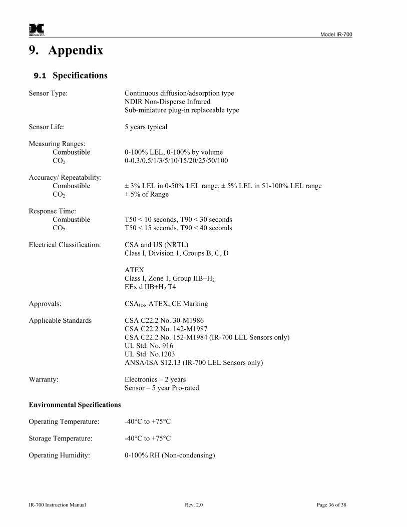
Model IR-700
9. Appendix
9.1 Specifications Sensor Type: Continuous diffusion/adsorption type
NDIR Non-Disperse Infrared Sub-miniature plug-in replaceable type
Sensor Life: 5 years typical Measuring Ranges:
Combustible 0-100% LEL, 0-100% by volume CO2 0-0.3/0.5/1/3/5/10/15/20/25/50/100
Accuracy/ Repeatability:
Combustible ± 3% LEL in 0-50% LEL range, ± 5% LEL in 51-100% LEL range CO2 ± 5% of Range Response Time:
Combustible T50 < 10 seconds, T90 < 30 seconds CO2 T50 < 15 seconds, T90 < 40 seconds Electrical Classification: CSA and US (NRTL)
Class I, Division 1, Groups B, C, D
ATEX Class I, Zone 1, Group IIB+H2 EEx d IIB+H2 T4
Approvals: CSAUS, ATEX, CE Marking Applicable Standards CSA C22.2 No. 30-M1986 CSA C22.2 No. 142-M1987 CSA C22.2 No. 152-M1984 (IR-700 LEL Sensors only) UL Std. No. 916 UL Std. No.1203 ANSA/ISA S12.13 (IR-700 LEL Sensors only) Warranty: Electronics – 2 years Sensor – 5 year Pro-rated Environmental Specifications Operating Temperature: -40°C to +75°C Storage Temperature: -40°C to +75°C Operating Humidity: 0-100% RH (Non-condensing)
IR-700 Instruction Manual Rev. 2.0 Page 36 of 38

Model IR-700
Electrical Specifications
Input Voltage: 11-30 VDC Power Consumption: Normal operation = 68mA (<1.7 watt); Maximum = 85mA (2 watts) RFI/EMI Protection: Complies with EN61326 Analog Output: Linear 4-20mA DC current 1000 ohms maximum loop load @ 24VDC 0mA All Fault Diagnostics 2mA In-Calibration 4-20mA 0-100% full-scale 22mA Over-range condition Serial Output: RS-485 Modbus™ RTU Baud Rate 9600 BPS (9600,N,8,1 Half Duplex) Status Indicators: 4-digit LED Display with gas concentration, full-script menu
prompts for AutoSpan, Set-up Options, and Fault Reporting Faults Monitored: Loop Fault, Input Voltage Fault, Zero Fault, Sensor Fault, Processor Fault, Memory Fault, Calibration Fault(s) Cable Requirements: Power/Analog: 3-wire shielded cable
Maximum distance is 13,300 feet with 14 AWG Serial Output: 2-wire twisted-pair shielded cable specified for RS-485 use Maximum distance is 4,000 feet to last sensor Mechanical Specifications Length: 7.6 inches (190 mm), Includes Splashguard Width: 2.2 inches (55 mm) Weight: 2.5 lbs (1.2 Kg) Mechanical Connection: ¾” Male NPT threaded connection Electrical Connection: Six 18 gauge wire leads - 5.5” long
9.2 Spare Parts, Sensor Accessories, Calibration Equipment
Part Number Spare Parts 927-215500-100 IR-700 Intelligent Transmitter Module (ITM) 602-003152-000 Model 700 Housing Bottom Assembly (includes Flame Arrestor) 370-3658CH-700 Replacement Plug-in IR Combustible Gas Sensor 370-865878-700 Replacement Plug-in CO2 Sensor (Ranges ≤ 5%) 370-287724-700 Replacement Plug-in CO2 Sensor (Ranges ≥10%) 500-003087-100 Transient Protection PCA
IR-700 Instruction Manual Rev. 2.0 Page 37 of 38

Model IR-700
IR-700 Instruction Manual Rev. 2.0 Page 38 of 38
Sensor Accessories 897-850800-000 NEMA 7 Aluminum Enclosure less cover – 3 port 897-850400-000 NEMA 7 Aluminum Enclosure Cover (Blank) 897-850801-316 NEMA 7 316SS Enclosure less cover – 3 port 897-850401-316 NEMA 7 316SS Enclosure Cover (Blank) 613-120000-700 Sensor Splashguard with integral Cal-Port 613-2R0000-000 Remote Calibration Adapter 943-002273-000 Harsh Environment Sensor guard 327-000000-000 Programming Magnet 960-202200-000 Condensation prevention packet (for J-Box replace annually)
Calibration Accessories 943-000006-132 Threaded Calibration Adapter 943-020000-000 Span Gas Kit: Includes calibration adapter, In-Line Humidifying Tube,
200 cc/min fixed flow regulator, and carrying case. (Does not include gas).
942-520124-050 Span Gas cylinder: 50% LEL Methane balance air Contains 104 liters of gas and is good for 175 calibrations
942-400123-XXX Span Gas Cylinder with CO2 balance air. (XXX denotes % by volume concentration i.e. 10% = “-010”)
943-090005-502 200 cc/min Fixed Flow Regulator for span gas bottle
Recommend Spare Parts for 2 Years 927-215500-100 IR-700 Intelligent Transmitter Module (ITM) 602-003152-000 Housing Bottom Assembly (includes Flame Arrestor) 370-3658CH-700 Replacement Plug-in IR Combustible Gas Sensor 370-865878-700 Replacement Plug-in CO2 Sensor (Ranges ≤ 5%) 370-287724-700 Replacement Plug-in CO2 Sensor (Ranges ≥10%) 500-003087-100 Transient Protection PCA 960-202200-000 Condensation prevention packet (for J-Box replace annually)
9.3 Model IR-700 Engineering Drawings 1) IR-700 Series Breakaway and Wiring 2) IR-700 Series Wiring, Dimensional, and Wiring
Shipping Address: 3200 A-1 Research Forest Dr., The Woodlands Texas 77381 Mailing Address: P.O. Box 8067, The Woodlands Texas 77387-8067
Phone: 888.367.4286, 281.367.4100 • Fax: 281.292.2860 • www.detcon.com • [email protected]