Embed Size (px)
Citation preview
ProxSense®
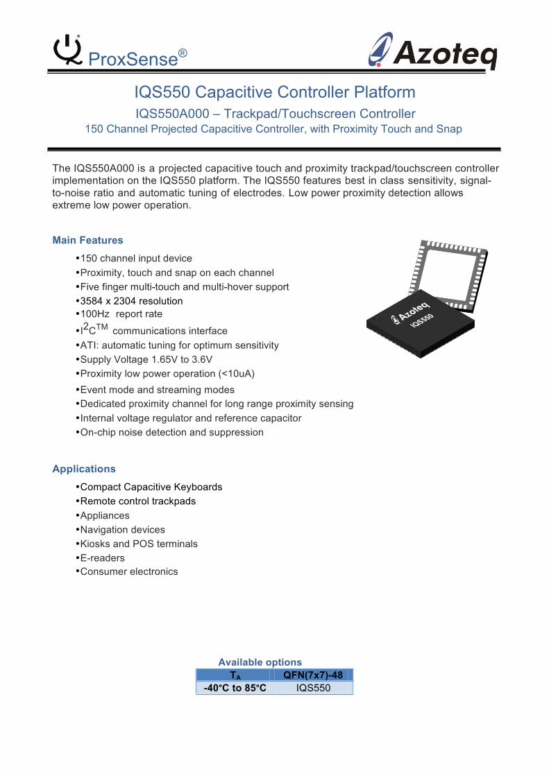
IQS550 Capacitive Controller Platform IQS550A000 – Trackpad/Touchscreen Controller
150 Channel Projected Capacitive Controller, with Proximity Touch and Snap The IQS550A000 is a projected capacitive touch and proximity trackpad/touchscreen controller implementation on the IQS550 platform. The IQS550 features best in class sensitivity, signal-to-noise ratio and automatic tuning of electrodes. Low power proximity detection allows extreme low power operation.
Main Features
• 150 channel input device • Proximity, touch and snap on each channel • Five finger multi-touch and multi-hover support • 3584 x 2304 resolution • 100Hz report rate
• I2CTM communications interface • ATI: automatic tuning for optimum sensitivity • Supply Voltage 1.65V to 3.6V • Proximity low power operation (<10uA) • Event mode and streaming modes • Dedicated proximity channel for long range proximity sensing • Internal voltage regulator and reference capacitor • On-chip noise detection and suppression
Applications
• Compact Capacitive Keyboards • Remote control trackpads • Appliances • Navigation devices • Kiosks and POS terminals • E-readers • Consumer electronics
Available options TA QFN(7x7)-48
-40°C to 85°C IQS550
IQ Switch®
ProxSense® Series Contents Trackpad Firmware Datasheet for IQS550 .................................................................................................................. 1
1 Overview ............................................................................................................................................................ 5
2 Packaging and Pin-‐out ........................................................................................................................................ 6
2.1 QFN48................................................................................................................................................................ 6 3 ProxSense® Module ............................................................................................................................................ 8
3.1 Individual Channels ........................................................................................................................................... 8
3.2 Normal Mode Charging ..................................................................................................................................... 8
3.3 ProxMode Charging........................................................................................................................................... 8
3.4 Automatic Mode Switching ............................................................................................................................... 9
3.5 Low Power Charging.......................................................................................................................................... 9 3.5.1 Low-‐Power with Automatic Mode Switching ............................................................................................... 9 3.5.2 Low-‐Power in Normal Mode ......................................................................................................................... 9 3.5.3 Low-‐Power in ProxMode............................................................................................................................... 9
3.6 Data Report Rate............................................................................................................................................... 9
3.7 Count Value Filter ............................................................................................................................................ 10 3.7.1 Filter in Normal Mode................................................................................................................................. 10 3.7.2 Filter in ProxMode ...................................................................................................................................... 10
3.8 Environmental Drift ......................................................................................................................................... 10 3.8.1 Long-‐Term Average Filter............................................................................................................................ 10 3.8.2 Filter Halt .................................................................................................................................................... 10
3.9 Auto Tuning (ATI) ............................................................................................................................................ 10
3.10 Snap (Metal-‐Dome click) ................................................................................................................................. 10
3.11 Proximity Sensitivity ........................................................................................................................................ 11
3.12 Touch Sensitivity .............................................................................................................................................. 11
3.13 Snap Sensitivity................................................................................................................................................ 12
3.14 Output Debounce ............................................................................................................................................ 12
3.15 Touch and Proximity XY Data .......................................................................................................................... 12
3.16 Position Tracking ............................................................................................................................................. 13
3.17 Touch Co-‐ordinate Filtering ............................................................................................................................. 13 3.17.1 Dynamic Filter......................................................................................................................................... 13 3.17.2 Static Filter.............................................................................................................................................. 13
3.18 Hover / Prox Co-‐ordinate Filtering.................................................................................................................. 13
3.19 Position adjustment / Calibration................................................................................................................... 13
3.20 Touch Strength ................................................................................................................................................ 13
3.21 Physical Layout ................................................................................................................................................ 13 4 Additional Features ...........................................................................................................................................14
Copyright © Azoteq (Pty) Ltd IQS550 Trackpad Datasheet Page 2 of 50 All Rights Reserved. Revision 1.04 November 2012

IQ Switch®
ProxSense® Series
4.1 Event Mode Communication ........................................................................................................................... 14
4.2 RF Immunity .................................................................................................................................................... 14 4.2.1 Design Guidelines........................................................................................................................................ 14 4.2.2 RF detection ................................................................................................................................................ 14
4.3 Additional Non-‐Trackpad Channels ................................................................................................................ 14
4.4 Active Channels / Disabling Channels............................................................................................................. 15
4.5 POUT / TOUT ................................................................................................................................................... 15
4.6 Sleep ................................................................................................................................................................ 15 5 Communication .................................................................................................................................................16
5.1 I2C .................................................................................................................................................................... 16 5.1.1 Protocol....................................................................................................................................................... 16
5.2 Control Byte ..................................................................................................................................................... 17
5.3 I2C Read ........................................................................................................................................................... 17
5.4 I2C Write .......................................................................................................................................................... 17
5.5 End of Communication Session / Window ...................................................................................................... 17
5.6 Address-‐Command Description ....................................................................................................................... 17 5.6.1 Version Information Read (0x00) ................................................................................................................ 17 5.6.2 XY Data Read (0x01) .................................................................................................................................... 17 5.6.3 Proximity Status Read (0x02) ...................................................................................................................... 19 5.6.4 Touch Status Read (0x03) ........................................................................................................................... 19 5.6.5 Count Data Read (0x04) .............................................................................................................................. 20 5.6.6 Long-‐Term Average Data Read (0x05) ........................................................................................................ 21 5.6.7 ATI Compensation Read & Write (0x06) ..................................................................................................... 21 5.6.8 Port Control (0x07) ..................................................................................................................................... 21 5.6.9 Snap Status Read (0x08) ............................................................................................................................. 22 5.6.10 Control Settings (0x10) ........................................................................................................................... 22 5.6.11 Threshold Settings (0x11) ....................................................................................................................... 24 5.6.12 ATI Settings (0x12) .................................................................................................................................. 25 5.6.13 Filter Settings (0x13) ............................................................................................................................... 26 5.6.14 Timing Settings (0x14) ............................................................................................................................ 28 5.6.15 Channel Setup (0x15) ............................................................................................................................. 29 5.6.16 Hardware Config Settings (0x16) ............................................................................................................ 31 5.6.17 Active Channels (0x17) ........................................................................................................................... 32 5.6.18 Debounce Settings.................................................................................................................................. 33 5.6.19 ProxMode Proximity Status (0x20) ......................................................................................................... 34 5.6.20 ProxMode Count Data Read (0x21) ........................................................................................................ 34 5.6.21 ProxMode Long-‐Term Average Read (0x22)........................................................................................... 34 5.6.22 ProxMode ATI Compensation Read/Write (0x23) .................................................................................. 35 5.6.23 ProxMode ATI Settings (0x24) ................................................................................................................ 35
6 Circuit Diagram .................................................................................................................................................36
7 Electrical Characteristics....................................................................................................................................37
7.1 Absolute Maximum Ratings ............................................................................................................................ 37
7.2 Operating Conditions ...................................................................................................................................... 38 7.2.1 General Operating Conditions .................................................................................................................... 38 7.2.2 Power-‐up / Power-‐down Operating Conditions ......................................................................................... 38 7.2.3 Supply current characteristic ...................................................................................................................... 39
Copyright © Azoteq (Pty) Ltd IQS550 Trackpad Datasheet Page 3 of 50 All Rights Reserved. Revision 1.04 November 2012
IQ Switch®
ProxSense® Series
7.2.4 I/O port pin characteristics ......................................................................................................................... 39 General characteristics ............................................................................................................................................ 39 Output driving current ............................................................................................................................................. 41 NRST pin ................................................................................................................................................................... 41 7.2.5 Electrostatic discharge (ESD) ...................................................................................................................... 42 7.2.6 Thermal characteristics ............................................................................................................................... 43
8 Mechanical Dimensions ....................................................................................................................................44
8.1 IQS550 QFN(7x7)-‐48 Mechanical Dimensions ................................................................................................. 44
8.2 IQS550 Landing Pad Layout............................................................................................................................. 45 9 Device Marking .................................................................................................................................................46
10 Ordering Information ........................................................................................................................................46
Changes: ....................................................................................................................................................................47
Release v1.00 ........................................................................................................................................................... 47 Release v1.01 ........................................................................................................................................................... 47 Release v1.02 ........................................................................................................................................................... 47 Release v1.03 ........................................................................................................................................................... 48 Release v1.04 ........................................................................................................................................................... 48
Copyright © Azoteq (Pty) Ltd IQS550 Trackpad Datasheet Page 4 of 50 All Rights Reserved. Revision 1.04 November 2012

1 Overview
IQ Switch®
ProxSense® Series
The IQS550 is a capacitive sensing controller designed for multi-touch applications using projected capacitance touch panels. The device offers high sensitivity proximity/hover (PROX) detection and contact detection (TOUCH) through a selectable number of sensor lines (Rx‟s and Tx‟s).
Touch and proximity positions are calculated to provide multiple X-Y coordinates.
The device has an internal voltage regulator and Internal Capacitor Implementation (ICI) to reduce external components. Advanced on-chip signal processing capabilities yields a stable high performance capacitive controller with high sensitivity.
The controller uses the principle of projected capacitance charge transfer on the trackpad. When a conductive object such as a human finger approaches the sense plate it will decrease the detected capacitance. Observing the measured results at various sensing points on the touchpad enables the controller to determine PROX and TOUCH on all channels, and accurately determine the coordinates on the touch area. Multiple touch positions can thus be obtained.
Due to the advanced sensitivity of the device, MULTIPLE non-contact (proximity hover) co- ordinates can also be obtained. These hover co-ordinates can be used to predict the touch co-ordinate of an approaching user, before the touch is made, allowing innovative user interface options.
Multiple filters are implemented to suppress and detect noise and track slow varying environmental conditions, and avoid effects of possible drift. The Auto Tuning (ATI) allows for the adaptation to a wide range of touch screens without using external components.
An innovative addition, known as a Snap (Click), is also available on each channel. This adds another output additional to the PROX and TOUCH of each channel.
The trackpad application firmware on the IQS550 is very flexible in design, and can incorporate standard touch sensors, trackpad / touchscreen areas (giving XY output data) and conventional snap-dome type buttons, all providing numerous outputs such as Prox, Touch, Snap, Touch Strength and actual finger position even before physical contact, all in one solution.
This datasheet applies to the following Azoteq version:
Product Number 40 / Project Number 0 / Version Number 55
Copyright © Azoteq (Pty) Ltd IQS550 Trackpad Datasheet Page 5 of 50 All Rights Reserved. Revision 1.04 November 2012
IQS
550 1i X
xxxx xx X
xx xxx
Rx0
A 1
3 48
Tx1
3
Rx0
B 1
4 47
Tx1
2
Rx1
A 1
5 46
Tx1
1
Rx1
B 1
6 45
Tx1
0
Rx2
A 1
7 44
Tx9
Rx2
B 1
8 43
Tx8
Rx3
A 1
9 42
Tx7
Rx3
B 2
0 41
Tx6
Rx4
A 2
1 40
Tx5
39 T
x4
Rx4
B 2
2
Rx5
A 2
3 38
VD
DIO
Rx5
B 2
4 37
VS
SIO
IQ Switch®
ProxSense® Series
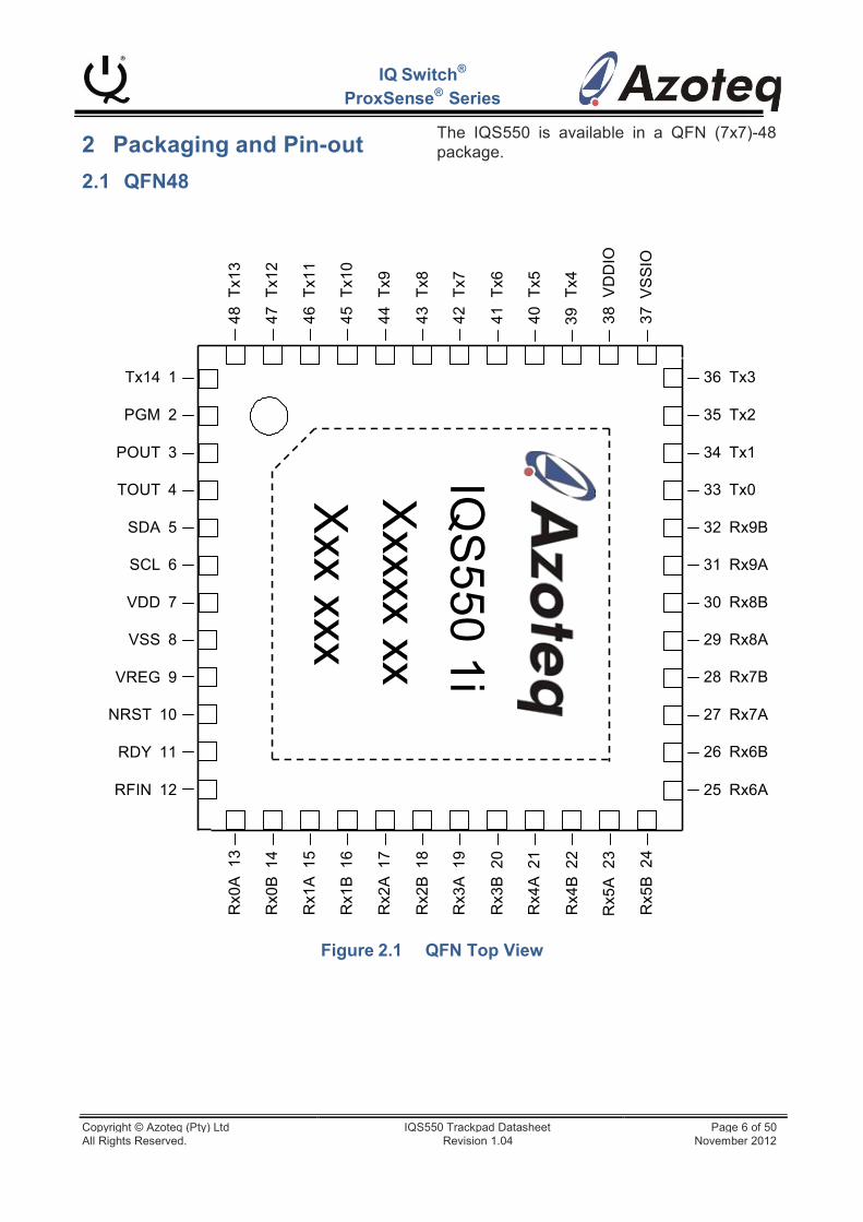
2 Packaging and Pin-out
2.1 QFN48
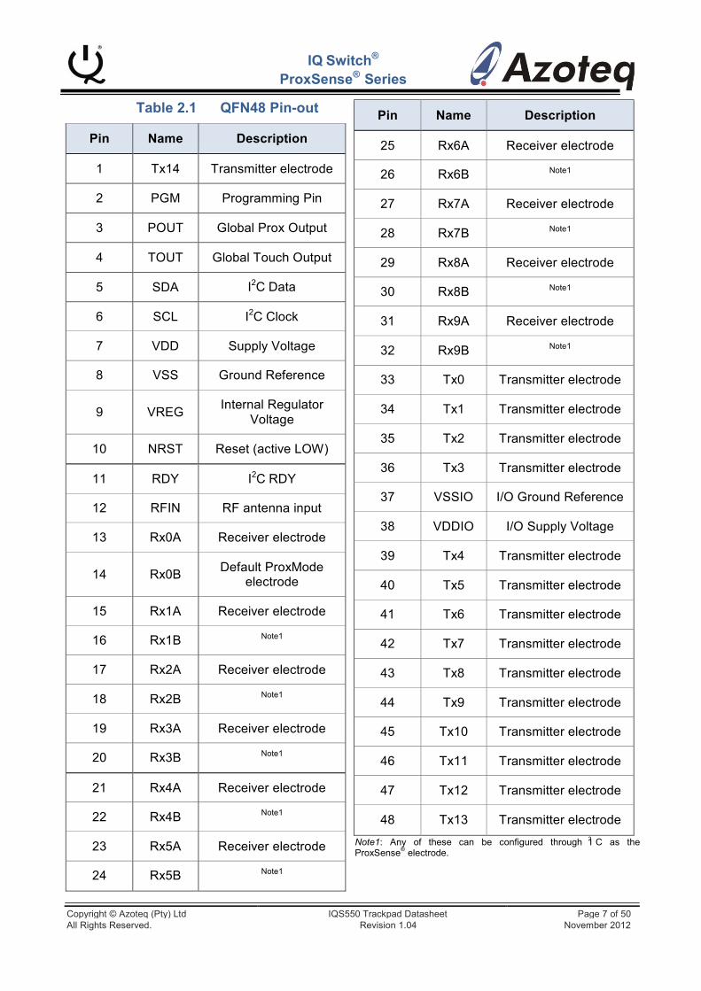
The IQS550 is available in a QFN (7x7)-48 package.
Tx14 1
PGM 2
POUT 3
TOUT 4
SDA 5
SCL 6
VDD 7
VSS 8
VREG 9
NRST 10
RDY 11
RFIN 12
36 Tx3 35 Tx2 34 Tx1 33 Tx0 32 Rx9B 31 Rx9A 30 Rx8B 29 Rx8A 28 Rx7B 27 Rx7A 26 Rx6B 25 Rx6A
Figure 2.1 QFN Top View
Copyright © Azoteq (Pty) Ltd IQS550 Trackpad Datasheet Page 6 of 50 All Rights Reserved. Revision 1.04 November 2012
Pin
Name
Description
25
Rx6A
Receiver electrode
26
Rx6B Note1
27
Rx7A
Receiver electrode
28
Rx7B Note1
29
Rx8A
Receiver electrode
30
Rx8B Note1
31
Rx9A
Receiver electrode
32
Rx9B Note1
33
Tx0
Transmitter electrode
34
Tx1
Transmitter electrode
35
Tx2
Transmitter electrode
36
Tx3
Transmitter electrode
37
VSSIO
I/O Ground Reference
38
VDDIO
I/O Supply Voltage
39
Tx4
Transmitter electrode
40
Tx5
Transmitter electrode
41
Tx6
Transmitter electrode
42
Tx7
Transmitter electrode
43
Tx8
Transmitter electrode
44
Tx9
Transmitter electrode
45
Tx10
Transmitter electrode
46
Tx11
Transmitter electrode
47
Tx12
Transmitter electrode
48
Tx13
Transmitter electrode
Pin
Name
Description
1
Tx14
Transmitter electrode
2
PGM
Programming Pin
3
POUT
Global Prox Output
4
TOUT
Global Touch Output
5
SDA I2C Data
6
SCL I2C Clock
7
VDD
Supply Voltage
8
VSS
Ground Reference
9
VREG
Internal Regulator Voltage
10
NRST
Reset (active LOW)
11
RDY I2C RDY
12
RFIN
RF antenna input
13
Rx0A
Receiver electrode
14
Rx0B
Default ProxMode electrode
15
Rx1A
Receiver electrode
16
Rx1B Note1
17
Rx2A
Receiver electrode
18
Rx2B Note1
19
Rx3A
Receiver electrode
20
Rx3B Note1
21
Rx4A
Receiver electrode
22
Rx4B Note1
23
Rx5A
Receiver electrode
24
Rx5B Note1
2
ProxSense® electrode.
IQ Switch®
ProxSense® Series
Table 2.1 QFN48 Pin-out
Note1: Any of these can be configured through I C as the
Copyright © Azoteq (Pty) Ltd IQS550 Trackpad Datasheet Page 7 of 50 All Rights Reserved. Revision 1.04 November 2012
3 ProxSense® Module
IQ Switch®
ProxSense® Series
consisting of the acquisition of 10 receiver channels.
The device contains a ProxSense® module that uses patented technology to provide detection of PROX and TOUCH, and calculate X and Y touch and/or proximity coordinates. A combination of hardware and software is used to obtain a set of measurements used for calculating the respective outputs.
An additional „Snap‟ output is now available which adds further conventional button snap functionality above the trackpad area.
The system can operate in a Normal- or Prox- Mode charging configuration. In both of these a low-power charging scheme can also be implemented.
3.1 Individual Channels
On a trackpad type pattern (typically a diamond shape layout), each intersection of an Rx and Tx row/column forms a channel. Each channel has a count value, Long-Term Average, Proximity, Touch and Snap (if
Communication is only done once all these timeslots are completed.
3.3 ProxMode Charging
An additional ProxMode charging scheme is selectable, and aimed at providing long range proximity detection, useful for implementing low-power modes during periods of no user activity. The ProxMode channel is configurable, and can function in either self- or projected- capacitive mode. Standard sensor electrode design for self or projected channels must be adhered for optimal proximity sensing.
The system performs a ProxMode channel acquisition (while waiting in a low-power state for the conversion to complete). Once complete, the data is processed, updating the proximity status. A low duty cycle can then also be selected, further reducing the total current consumption. With the superior
®
enabled) status. The default on the IQS550 sensitivity of the ProxSense hardware, the
device is 15x10 thus giving 150 channels in total.
Any channels not forming part of the trackpad area (see Section 4.3) can be used as separate sensors, and designed with any projected sensor pattern (Rx + Tx) as required by the design.
Each channel is limited in having a count value < 20000. If the ATI setting or hardware causes samples higher than this, the conversion will be stopped, and a value of „0‟ will be read for that relevant count value.
3.2 Normal Mode Charging
The sensors are scanned one Tx transmitter at a time, until all have completed, with all enabled Rx‟s charging in each Tx „time-slot‟. This then provides all the sample data for the touch panel, which can be used to obtain Long-term Average values, Prox and Touch status, and finally full XY co-ordinate information.
In a 15x10 system (15 Tx and 10 Rx), 15 conversion timeslots occur, with each timeslot
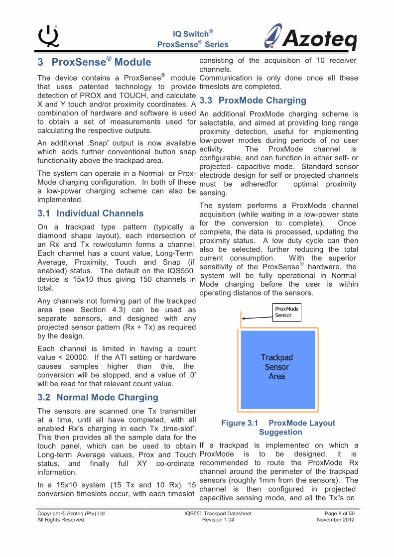
system will be fully operational in Normal Mode charging before the user is within operating distance of the sensors.
ProxMode Sensor
Trackpad Sensor Area
Figure 3.1 ProxMode Layout Suggestion
If a trackpad is implemented on which a ProxMode is to be designed, it is recommended to route the ProxMode Rx channel around the perimeter of the trackpad sensors (roughly 1mm from the sensors). The channel is then configured in projected capacitive sensing mode, and all the Tx‟s on
Copyright © Azoteq (Pty) Ltd IQS550 Trackpad Datasheet Page 8 of 50 All Rights Reserved. Revision 1.04 November 2012

IQ Switch®
ProxSense® Series
the trackpad sensors are enabled. This gives a good proximity sensor in the trackpad area.
3.4 Automatic Mode Switching
With this enabled, automatic interaction and switching between Normal- and ProxMode charging is achieved. For the automatic mode (and also low-power charging) a selectable ModeTime is used.
After being correctly configured, the system will operate in ProxMode, until a proximity event is sensed on the ProxMode channel. At this point the system will switch to Normal Mode charging, ready to sense user interaction with the trackpad channels.
The system will revert back to ProxMode charging if no prox, touch or snap condition is found on the Normal Mode channels for a period of ModeTime.
When in ProxMode, a Normal Mode conversion will automatically take place roughly every 4s, but no communication for this cycle will be presented. This cycle is simply to keep the Long-Term Average values of the Normal Mode channels up to date.
3.5 Low Power Charging
By enabling low-power, the device will add a sleep between conversions. If no prox, touch or snap is sensed for ModeTime, then the system will go into the low duty-cycle charging mode. As soon as a channel output is sensed, the system will resume full-speed charging. Introducing this low-power duty cycle into the system naturally decreases total power consumption of the device, dependant on the selected LPTime.
3.5.1 Low-Power with Automatic Mode Switching
If it is possible to have a ProxMode sensor, the best is to use the system in automatic mode switching, combined with low-power charging. This will give by far the lowest power consumption, and works as follows:
The system charges in ProxMode until a PROX event occurs, and since automatic mode is enabled, it will switch to Normal Mode charging which occurs at full-speed (no low-
power). If no activity occurs for ModeTime, then the system will revert to ProxMode charging. Here it will continue at full-speed for a further ModeTime, and after this, low-power charging will take place on the ProxMode channel.
This gives the lowest power consumption, combined with a possibility of good range proximity (sensor and system dependent) which helps with the wake-up response time of the system.
3.5.2 Low-Power in Normal Mode
If automatic mode is NOT selected, the system will work as follows in Normal Mode (possibly the hardware does not allow for a ProxMode electrode):
After ModeTime of no prox, touch or snap, the system will stay in Normal Mode, but all channels will with a low-power duty cycle. If an event is sensed on a Normal Mode channel, full-speed charging will commence immediately to provide fast response. This will not provide the same low power consumption as found in ProxMode, since more channels are usually processed in Normal Mode, thus increasing the consumption (longer/more processing means higher ratio of high current operation time versus sleep time).
3.5.3 Low-Power in ProxMode
If automatic mode is NOT selected, and the system is in ProxMode charging:
After a period of ModeTime of no PROX on the ProxMode sensor, the ProxMode channel will charge in the low-power mode. If a PROX is sensed on this channel, it will stay in ProxMode, and will charge at full-speed.
3.6 Data Report Rate
The report rate of the device depends on the charge transfer frequency, number of enabled channels, and the count value of the channels. The length of communications initiated by the master device will also affect the report rate. There is a maximum rate governed by the time taken to process the data, but the rate
Copyright © Azoteq (Pty) Ltd IQS550 Trackpad Datasheet Page 9 of 50 All Rights Reserved. Revision 1.04 November 2012
IQ Switch®
ProxSense® Series
can decreased if the other factors extend the cycle.
The frequency of the transfers can be adjusted. An optimal transfer frequency must be selected for a specific touch panel application by choosing the optimal setting.
High count values will give good resolution and proximity hover performance, but could decrease the report rate.
A guideline measurement was taken on a system with the following configuration:
- 10x15 hardware configuration.
- Count values of roughly 600 (Auto ATI used with Target = 600)
- I2C only reading XY data
- ATI C value = 7
This allows the device to adapt to environmental (slow moving) drift. To force an update, a reseed command can be executed.
3.8.2 Filter Halt
To ensure that the Long-Term Average filters do not adapt during a prox, touch or snap event, a filter halt scheme is implemented on the device. The designer can choose between filter halt times ranging from 0.5 to 127 seconds, in multiples of 500ms. Also „Always Halt‟ can be selected (value = 255). Once this filter halt time has elapsed, a recalibration (reseed) is executed, resetting all outputs and incorporating the current environment into the new baseline.
3.9 Auto Tuning (ATI)
The ATI is a sophisticated technology ®
With dual-touch input the report rate was implemented in the new ProxSense devices
~100Hz.
3.7 Count Value Filter
3.7.1 Filter in Normal Mode
To improve hover reliability, a count value filter is implemented in normal mode. Since this would greatly reduce the response rate for normal touch operation, it is only active when no touch or snap output is sensed. When these occur the filter is bypassed and fast response is achieved. This filter can also be disabled and adjusted.
3.7.2 Filter in ProxMode
For the ProxMode channel, a count value filter is implemented. This allows the user to increase the sensitivity of the ProxMode electrode drastically to obtain good proximity distance, whilst the filter retains the stability of the count values and thus the PROX output. The filter damping factor can be adjusted, and the filter can also be totally disabled.
3.8 Environmental Drift
The Long-Term Average (LTA) can be seen as the baseline or reference value.
3.8.1 Long-Term Average Filter
The Long-Term Average filter is calculated from the sample count value of each channel.
to allow optimal performance of the devices for a wide range of sensing electrode capacitances, without modification to external components. The ATI allows the tuning of two parameters, ATI Multiplier and ATI Compensation, to adjust the sample value for an attached sensing electrode.
ATI allows the designer to optimise a specific design by adjusting the sensitivity and stability through the adjustment of the ATI parameters.
With a selected ATI C value, the ATI Compensation can then be automatically configured for an adjustable channel target sample value by means of an automated ATI function.
The device requires that for optimal performance on the trackpad, all these channels must be configured to have similar sample values.
Different sets of settings exist for trackpad, non-trackpad and the ProxMode channel.
3.10 Snap (Metal-Dome click)
When adding a metal snap-dome button as the overlay to the trackpad pattern, an additional „Snap‟ function is available. The device is able to distinguish between a normal „touch‟ on the overlay and an actual button „snap‟, which depresses the metal dome onto
Copyright © Azoteq (Pty) Ltd IQS550 Trackpad Datasheet Page 10 of 50 All Rights Reserved. Revision 1.04 November 2012

IQ Switch®
ProxSense® Series
the Rx/Tx pattern. This output is referred to as a snap. The design must be configured so that a snap on the metal dome will result in a channels‟ sample value falling well below the Long-Term Average value for that channel. A few suggestions are:
Place the snap-dome directly above a
channel (thus exactly on the Rx-Tx junction)
Alternatively place the snap-dome in the centre of the diamond pattern, and add a round pad of the second sensor inside the diamond.
The snap-dome must consist of the standard metal dome or carbon circle pattern (or similar conductive material) on the inside of the dome.
This conductive dome must be of adequate size to provide good count value deviation below the Long-Term Average of the channel on a snap.
The conductive dome must however not be too big relative to the pitch of the Rx/Tx sensors, so as to not block the field lines for the trackpad sensing.
No electrical connection between the snap-dome and the Rx-Tx must be made. Usually PCB solder-mask is adequate. Optimally the sensors are covered by solder-mask, with the snap- dome directly above.
The snap-dome overlay must not have varying air-gaps between itself and the sensors. Thus having the overlay securely fastened to the PCB is ideal. A variable air-gap causes sporadic sensing, and gives unreliable data.
If required, the function can be enabled, and the snap bits are then available to the user, similar to the prox and touch status bits. The Long-Term Average filter halt is also implemented on snap outputs.
With the high level of sensitivity found on the device, a touch- / track-pad can now be projected through conventional keys, providing
full XY functionality behind these without requiring additional real-estate or sense ICs.
3.11 Proximity Sensitivity
The proximity threshold of the channels is calculated as a delta value of the count value relative to the Long-Term Average value. A PROX status is detected when the count value changes by more than the selected delta. Any 8 bit value can be used as the proximity threshold delta value.
A different threshold is available for the trackpad, non-trackpad and the ProxMode channels.
Note: For the trackpad channels (projected capacitive) the samples will increase with user interaction, thus the threshold is this value ABOVE the Long-Term Average. However for the ProxMode channel, if self capacitive mode is selected, the samples will decrease during user interaction, thus the threshold is this value BELOW the Long-Term Average.
If ProxMode Reverse sensing (ControlSettings1 byte) is enabled, the proximity output will trigger on a positive or negative change. It has been found that for certain battery applications, even though projected capacitance is selected, a self- capacitive effect can occur.
3.12 Touch Sensitivity
The touch sensitivity of the channels is a user defined threshold calculated as a ratio of count value to the Long-Term Average for each channel. Note that a user touching the sensor will cause the count value to increase. A smaller fraction will thus be a more sensitive threshold (for example 1/64 is more sensitive than 1/16)
The touch threshold for a specific channel is calculated as follows:
Threshold = LTA x (1 + Multiplier / 2SHIFTER)
where the MULTIPLIER and SHIFTER values can be adjusted.
Copyright © Azoteq (Pty) Ltd IQS550 Trackpad Datasheet Page 11 of 50 All Rights Reserved. Revision 1.04 November 2012

IQ Switch®
ProxSense® Series
If the count value increases with more than this threshold value, then a touch condition is true.
A touch is NOT calculated for the ProxMode channel, but two sets of thresholds are available for the trackpad and non-trackpad channels
3.13 Snap Sensitivity
The Snap threshold is a delta value BELOW the Long-Term Average of the channel. When a snap is performed, a self capacitive effect is observed, and the sample value will decrease. To be able to distinguish between a snap, and a normal touch release, the hardware must be designed so that a snap forces the samples below the Long-Term Average value. A 16-bit value can be selected for this delta.
When a user touches the key, the samples on that specific channel will increase and a normal touch and prox output will trigger. When the user pushes the button down (snap), the samples will decrease (removing the prox and touch outputs) below the Long- Term Average value, and a snap output can be observed.
One global Snap threshold is implemented.
3.14 Output Debounce
All the channel outputs (proximity, touch and snap) are debounced according to the selectable debounce values. The default debounce values are shown in the table, note that a debounce value = 1 means that two samples satisfying the condition must be met before the output is activated. A debounce value of 0 thus means no debouncing takes place. The default touch debounce setting is set to no debouncing. This is due to the fact that with a 15x10 sensor, debouncing adds too much delay, and fast movements on the touchpanel cannot be debounced fast enough to provide reliable XY output data. With the advanced sensitivity of the sensors, a touch is regarded as a large deviation this does not pose any problems.
Table 3.1 Debounce values
Set
Clear
Proximity
4
4
Touch
0
0
Snap
1
1
3.15 Touch and Proximity XY Data
Five XY co-ordinates are available to the master. These are the 5 „hardest/biggest‟ touches/proximity points sensed on the sensor panel. The XY data is sent out in order, from hardest to least hard touch/prox. The IC however tracks each specific XY position from cycle to cycle (since they will move in position relative to their touch strength) and attaches the relating ID tag with each co-ordinate.
5 unique ID tags are available for TOUCH co- ordinates, namely values of 1-5, and 5 ID‟s for HOVER co-ordinates, namely 129 - 133.
256 steps are implemented between the relative Rx‟s and also between the relative Tx‟s, giving x coordinates that range from 0 to (256 x (TrackpadRxs-1)). The Y coordinates will have an output range from 0 to (256 x (TrackpadTxs-1)). Thus in a 15x10 system: (0 < y < 3584) and (0 < x < 2304).
It is not necessary to read the proximity, touch or snap status data to obtain a global picture of the touch panel status. The XY data stream contains all information required during normal operation.
The XY data stream is lead by an information byte showing certain status bits, as well as how many active co-ordinates are currently available (the number of touches + hovers).
For each co-ordinate, the ID tag is sent first, followed by an X co-ordinate, a Y co-ordinate, and finally the touch strength. All of these are 2 bytes each.
A total of 5 co-ordinates are always available to be read, but if the information byte indicates fewer co-ordinates are active, the master is allowed to stop reading after the relative co- ordinate. A global snap indication bit is also
Copyright © Azoteq (Pty) Ltd IQS550 Trackpad Datasheet Page 12 of 50 All Rights Reserved. Revision 1.04 November 2012
IQ Switch®
ProxSense® Series
available in the information byte and will indicate when the individual status bits must be read.
3.16 Position Tracking
Position filtering is performed on-chip, and is configurable through the I2C interface. For filtering to be possible, position tracking is required.
Each calculated XY co-ordinate must be matched with the previous co-ordinates to be able to identify a specific point. The co- ordinates are identified by an identification value (ID) that is provided along with each XY data packet. This ID allows the master to differentiate between Touch and Hover co- ordinates, and also track specific points.
3.17 Touch Co-ordinate Filtering
Selecting between dynamic, static or no filtering is possible.
3.17.1 Dynamic Filter
Relative to the speed of movement of a co- ordinate, a dynamic filter is implemented on the touch co-ordinates.
The filter dynamically adjusts the amount of filtering (damping factor) relative to the movement of the XY co-ordinate. When fast response is required, less filtering is done. Similarly when a co-ordinate is stationary or moving at a slower speed, then more filtered XY co-ordinates are obtained.
3.17.2 Static Filter
Co-ordinates filtered with a fixed but configurable damping factor are obtained when using the static filter. It is recommended that the dynamic filter be used due to the advantages of a dynamically changing damping value.
3.18 Hover / Prox Co-ordinate
touch points, since the hover operates closer to the system‟s noise floor.
3.19 Position adjustment / Calibration
No position calibration is required. The position data starts at the centre of the first Rx/Tx electrode, and ends at the centre of the last Rx/Tx electrode.
3.20 Touch Strength
This value indicates the strength of the touch/proximity with the touch screen. The touch strength information can be used to add extra effects in applications. Two possible applications would be broadening the paintbrush width while drawing on the touch screen, or sensing presses of the finger while moving across a touch panel, without lifting your finger. The calculated value of the touch strength can be seen as providing „Z‟ direction data.
This strength value varies according to the sensitivity of the sensors.
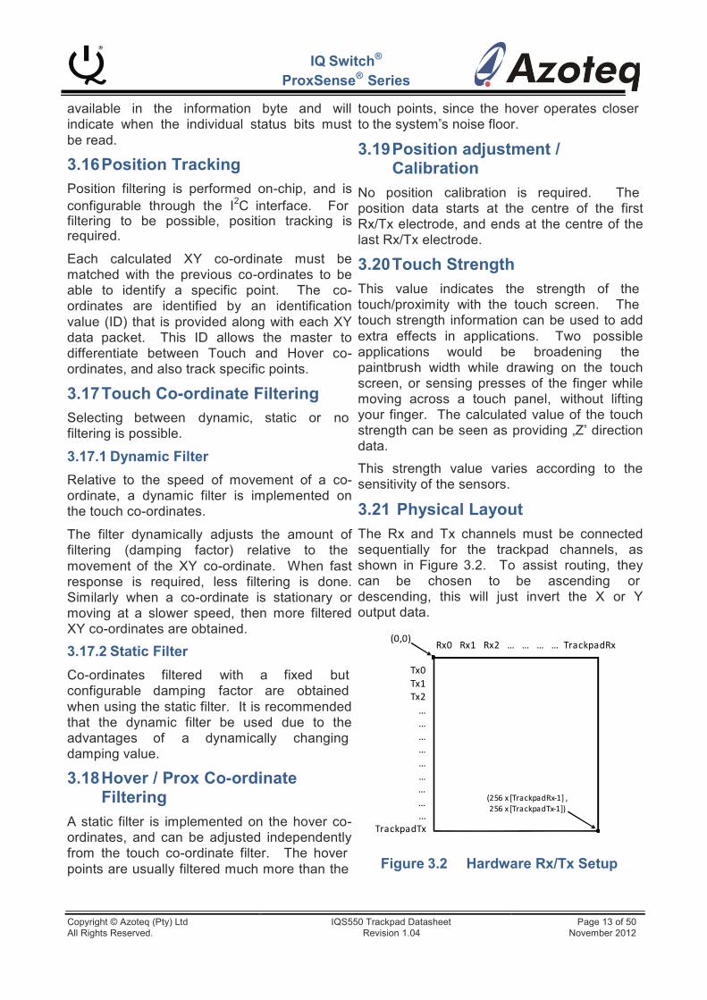
3.21 Physical Layout
The Rx and Tx channels must be connected sequentially for the trackpad channels, as shown in Figure 3.2. To assist routing, they can be chosen to be ascending or descending, this will just invert the X or Y output data.
(0,0) Rx0 Rx1 Rx2 … … … … Tra ckpa dRx
Tx0 Tx1 Tx2 … … … … … …
Filtering
A static filter is implemented on the hover co- ordinates, and can be adjusted independently from the touch co-ordinate filter. The hover
… … ...
Tra ckpa dTx
(256 x [Tra ckpa dRx-‐1] , 256 x [Tra ckpa dTx-‐1])
points are usually filtered much more than the Figure 3.2 Hardware Rx/Tx Setup
Copyright © Azoteq (Pty) Ltd IQS550 Trackpad Datasheet Page 13 of 50 All Rights Reserved. Revision 1.04 November 2012

4 Additional Features
IQ Switch®
ProxSense® Series
or Snap, can be configured. For example all events except Touch can be disabled, and
4.1 Event Mode Communication
The device can be set up to bypass the communication window when no activity is sensed. This could be enabled if a master does not want to be unnecessarily interrupted during every charging cycle. The communication will resume (RDY will indicate available data) if a proximity, touch or snap is sensed. It is recommended that the RDY be placed on an interrupt-on-pin-change input on the master.
As soon as the active output is no longer sensed, one communication cycle will still be available to be able to read that this event has ended, and then the communication will again cease until further interaction with the sensors are observed.
Using the Event Mode will typically work as follows: The master sends a command to enable event mode. The device then continually does conversions without interaction (communication) with the master, until a proximity, touch or snap event occurs, which is most likely the first time that the master will be interested in the data. The master reads data during the communication windows, until the event is over, and then the communication windows will again be bypassed.
If however the master would like to force communication session, it must perform a single byte read from the device at any time (obviously without the need for RDY to go HIGH, which it won‟t since communication is skipped). The master will read one byte with a value of 0xA3, and then the master gives an I2C STOP. This shows that a request for a communication session is successful. Now when the next set of data is ready, a temporary communication session will be forced (and RDY will be set as usual to indicate this). This will however not disable Event Mode, and if this is required, it must be disabled during this single temporary window.
The different events to trigger the Event Mode, namely ProxMode Proximity, Proximity, Touch
then communication will only be available when a touch output is detected.
4.2 RF Immunity
The IQS550 has immunity to high power RF noise. In this section general design guidelines will be given to improve noise immunity and the noise detection function is explained.
4.2.1 Design Guidelines
To improve the RF immunity extra decoupling capacitors are suggested on VREG and VDD.
Place a 100pF in parallel with the 1uF ceramic on VREG. Place a 1uF ceramic on VDD. All decoupling capacitors should be placed as close as possible to the VDD and VREG pads.
PCB ground planes also improve noise immunity.
4.2.2 RF detection
In cases of extreme RF interference, on-chip RF detection is provided. By connecting a suitable RF antenna to the RF input pin, it improves detection of RF noise. The RF noise is identified on-chip, and suitable steps are taken to block the corrupt samples from influencing the output data. In standard designs this will not be necessary, since the on-chip sensing has a good immunity to noise interference.
4.3 Additional Non-Trackpad Channels
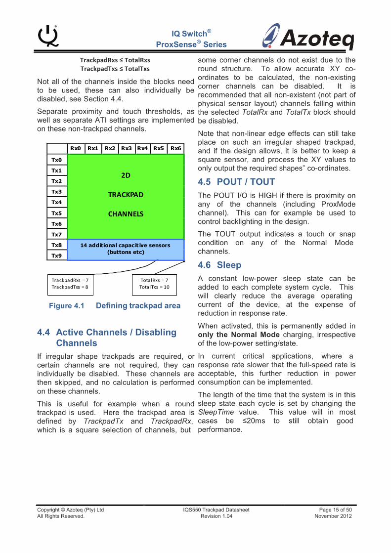
If there is a requirement for standard projected sensors that do no form part of the trackpad area, then this can be configured. The trackpad sensors can be reduced by defining the TrackpadRx and TrackpadTx parameters. These define where the trackpad ends. Any Rx/Tx channels remaining can be used as standard capacitive sensing buttons/sensors, and only proximity, touch and snap data is processed on these channels, no XY data. An example is shown in Figure 4.1. Here the trackpad area will be 8x7, and an additional 14 sensors are available outside of this area. Clearly the following must be true:
Copyright © Azoteq (Pty) Ltd IQS550 Trackpad Datasheet Page 14 of 50 All Rights Reserved. Revision 1.04 November 2012
Rx0 Rx1 Rx2 Rx3 Rx4 Rx5 Rx6 Tx0
2D
TRACKPAD
CHANNELS
Tx1 Tx2 Tx3 Tx4 Tx5 Tx6 Tx7 Tx8 14 additiona l capac it ive sensors
(buttons etc) Tx9
IQ Switch®
ProxSense® Series
TrackpadRxs ≤ TotalRxs TrackpadTxs ≤ TotalTxs
Not all of the channels inside the blocks need to be used, these can also individually be disabled, see Section 4.4.
Separate proximity and touch thresholds, as well as separate ATI settings are implemented on these non-trackpad channels.
some corner channels do not exist due to the round structure. To allow accurate XY co- ordinates to be calculated, the non-existing corner channels can be disabled. It is recommended that all non-existent (not part of physical sensor layout) channels falling within the selected TotalRx and TotalTx block should be disabled.
Note that non-linear edge effects can still take place on such an irregular shaped trackpad, and if the design allows, it is better to keep a square sensor, and process the XY values to only output the required shapes‟ co-ordinates.
4.5 POUT / TOUT
The POUT I/O is HIGH if there is proximity on any of the channels (including ProxMode channel). This can for example be used to control backlighting in the design.
The TOUT output indicates a touch or snap condition on any of the Normal Mode channels.
4.6 Sleep
Tra ckpa dRxs = 7 Tra ckpa dTxs = 8
Tota l Rxs = 7 Tota l Txs = 10
A constant low-power sleep state can be added to each complete system cycle. This will clearly reduce the average operating
Figure 4.1 Defining trackpad area
4.4 Active Channels / Disabling
Channels
If irregular shape trackpads are required, or certain channels are not required, they can individually be disabled. These channels are then skipped, and no calculation is performed on these channels.
This is useful for example when a round trackpad is used. Here the trackpad area is defined by TrackpadTx and TrackpadRx, which is a square selection of channels, but
current of the device, at the expense of reduction in response rate.
When activated, this is permanently added in only the Normal Mode charging, irrespective of the low-power setting/state.
In current critical applications, where a response rate slower that the full-speed rate is acceptable, this further reduction in power consumption can be implemented.
The length of the time that the system is in this sleep state each cycle is set by changing the SleepTime value. This value will in most cases be ≤20ms to still obtain good performance.
Copyright © Azoteq (Pty) Ltd IQS550 Trackpad Datasheet Page 15 of 50 All Rights Reserved. Revision 1.04 November 2012
0x04
Count Values
R
0x05
Long-Term Averages
R
0x06
ATI Compensation
R/W
0x07
Port Control
R/W
0x08
Snap Status
R
0x10
Control Settings
R/W
0x11
Threshold Settings
R/W
0x12
ATI Settings
R/W
0x13
Filter Settings
R/W
0x14
Timing Settings
R/W
0x15
Channel Setup
R/W
0x16
Hardware Config Settings
R/W
0x17
Active Channels
R/W
0x18
Debounce Settings
R/W
0x20
PM Proximity Status
R
0x21
PM Count Values
R
0x22
PM Long-Term Averages
R
0x23
PM ATI Compensation
R/W
0x24
PM ATI Settings
R/W
Command Value
Command Description
Read/ Write
0x00
Version Info
R
0x01*
XY Data (default)
R*
0x02
Proximity Status
R
0x03
Touch Status
R
5 Communication
5.1 I2C
IQ Switch®
ProxSense® Series
The device can communicate in I2C using the standard communication protocol. An additional RDY signal is added which indicates when the communication window is available, it is thus optimal for response rate to use the RDY as a communication trigger, but polling is also available as a less attractive option. Designing the RDY to connect to an interrupt-on-change input is recommended for easier implementation and optimal response time.
The first communication window is available before the device performs any sensing or calculations, to allow initial configuration to take place.
Standard I2C clock stretching can occur, so monitoring the availability of the SCL is required, as per usual I2C protocol.
5.1.1 Protocol The I2C currently employs an „address- command‟ type structure instead of a memory map. What this means is that data bytes cannot be individually addressed, but can be obtained by configuring a relevant address- command on the device to specify which blocks of data to read or write. Specific data is thus grouped together, and identified / accessed by means of the „address-command‟ relating to the specific group.
Table 5.1 I2C Address- Command Structure
For example, to read out the proximity status bytes, the following must be done:
START -‐-‐> CONTROL BYTE(Write) -‐-‐>
0x02 (proximity read address-‐command) -‐-‐> REPEATED-‐START -‐-‐>
CONTROL BYTE(Read) -‐-‐> ProxByte[0] -‐>
... ProxByte[TotalTx-‐1] -‐-‐> STOP
Copyright © Azoteq (Pty) Ltd IQS550 Trackpad Datasheet Page 16 of 50 All Rights Reserved. Revision 1.04 November 2012

1
1
1
0
1
0
0 R/W
S
ACK ACK
NACK S
S Adr + WRITE ACK ACK S Adr + READ ACK NACK S
S Adr + WRITE ACK ACK ACK ACK S
5.2 Control Byte
IQ Switch®
ProxSense® Series
5.5 End of Communication
The 7-bit device address is „1110100‟. Currently the sub-address is fixed at „00‟.
7 bit address
MSB LSB
I2C Group Sub-addresses
Figure 5.1 I2C Control Byte
5.3 I2C Read
To read from the device a current address read can be performed. This assumes that the address-command is already setup as desired.
Current Address Read
Session / Window Similar to other Azoteq I2C devices, to end the communication session, an I2C STOP is given. When sending numerous read and write commands in one communication cycle, a repeated start command must be used to string them together (since a STOP will jump out of the communication window, which is not desired).
The STOP ends the communication, RDY goes LOW, and the device will return to process a new set of data. Once this is obtained, the communication window will again become available (RDY set HIGH).
5.6 Address-Command Description
Start Control Byte
Data n
Data n+1
Stop In the address-commands, the length of the
available data is often relative to the total Rx and Tx channels configured on the device. To
Figure 5.2 Current Address Read
If the address-command must first be specified, then a random read must be performed. In this case a WRITE is initially performed to setup the address-command, and then a repeated start is used to initiate the READ section.
Random Read
indicate the length of these address- commands, the terms TotalTxs and TotalRxs will be used.
Most of the commands allow the master to Read/Write certain data. However in normal operation initially only the XY Data Read is recommended, since it gives a good summary of all required data. The other address-
Start Control Byte Address- command Start Control Byte Data n Stop commands should only be used for
setup/configuration, or when needed.
5.6.1 Version Information Read (0x00) Figure 5.3 Random Read
5.4 I2C Write
To write settings to the device a Data Write is performed. Here the Address-Command is always required, followed by the relevant data bytes to write to the device.
DATA WRITE
Here device version information can be obtained. A Product Number (2 bytes), Project Number (2 bytes), Major Release Number (1 byte) and Minor Release / Build Number (1 byte) are available, followed by a Hardware ID, and Hardware Revision (2 bytes each). A total of 10 bytes are thus available.
Start
Control Byte
Address- Command
Data n
Data n+1
Stop 5.6.2 XY Data Read (0x01)
Figure 5.4 Data Write
The default address-command at the start of each communication window is set to the XY data read address-command. This means that if a Current Address Read is performed at the start of the communications window without having set the address-command before this, then the XY Data will be obtained.
Copyright © Azoteq (Pty) Ltd IQS550 Trackpad Datasheet Page 17 of 50 All Rights Reserved. Revision 1.04 November 2012
IQ Switch®
ProxSense® Series
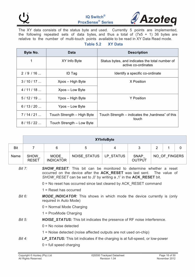
The XY data consists of the status byte and the following repeated sets of data bytes, relative to the number of multi-touch points
used. Currently 5 points are implemented, and thus a total of (7x5 + 1) 36 bytes are available to be read in XY Data Read mode.
Table 5.2 XY Data
Byte No.
Data
Description
1
XY Info Byte
Status bytes, and indicates the total number of active co-ordinates
2 / 9 / 16 ...
ID Tag
Identify a specific co-ordinate
3 / 10 / 17 ...
Xpos – High Byte
X Position
4 / 11 / 18 ...
Xpos – Low Byte
5 / 12 / 19 ...
Ypos – High Byte
Y Position
6 / 13 / 20 ...
Ypos – Low Byte
7 / 14 / 21 ...
Touch Strength – High Byte
Touch Strength – indicates the „hardness‟ of this touch
8 / 15 / 22 ...
Touch Strength – Low Byte
XYInfoByte
Bit
7
6
5
4
3
2
1
0
Name
SHOW_ RESET
MODE_ INDICATOR
NOISE_STATUS
LP_STATUS
SNAP_ OUTPUT
NO_OF_FINGERS
Bit 7: SHOW_RESET: This bit can be monitored to determine whether a reset occurred on the device after the ACK_RESET was last sent. The value of SHOW_RESET can be set to „0‟ by writing a „1‟ in the ACK_RESET bit.
0 = No reset has occurred since last cleared by ACK_RESET command
1 = Reset has occurred
Bit 6: MODE_INDICATOR: This shows in which mode the device currently is (only required in Auto Mode)
0 = Normal Mode Charging
1 = ProxMode Charging
Bit 5: NOISE_STATUS: This bit indicates the presence of RF noise interference.
0 = No noise detected
1 = Noise detected (noise affected outputs are not used on-chip)
Bit 4: LP_STATUS: This bit indicates if the charging is at full-speed, or low-power
0 = full speed charging
Copyright © Azoteq (Pty) Ltd IQS550 Trackpad Datasheet Page 18 of 50 All Rights Reserved. Revision 1.04 November 2012
IQ Switch®
ProxSense® Series
1 = low-power charging
Bit 3: SNAP_OUTPUT: This bit indicates if any snap outputs are active
0 = No active snap outputs
1 = At least one snap output
Bit 2-0 NO_OF_FINGERS: Indicates how many active XY data points (number of touches + hovers) there currently are.
5.6.3 Proximity Status Read (0x02)
The proximity of each individual channel can be retrieved from the IC. After writing the „Proximity Status‟ address-command, a read can be performed to obtain the proximity
bytes. The proximity of each channel found for a corresponding Tx can be obtained from two bytes. This gives a total number of proximity bytes of 2 x TotalTxs.
Table 5.3 Proximity Status Bytes
Byte
Data
Description
1
Prox[Tx0] – High Byte
Proximity bits (Rx0 = bit0, Rx1 = bit1 …)
2
Prox[Tx0] – Low Byte
3
Prox[Tx1] – High Byte
Proximity bits (Rx0 = bit0, Rx1 = bit1 …)
4
Prox[Tx1] – Low Byte
.
.
.
.
.
.
(2 x TotalTxs) - 1
Prox[Last Tx] – High Byte
Proximity bits (Rx0 = bit0, Rx1 = bit1 …)
(2 x TotalTxs)
Prox[Last Tx] – Low Byte
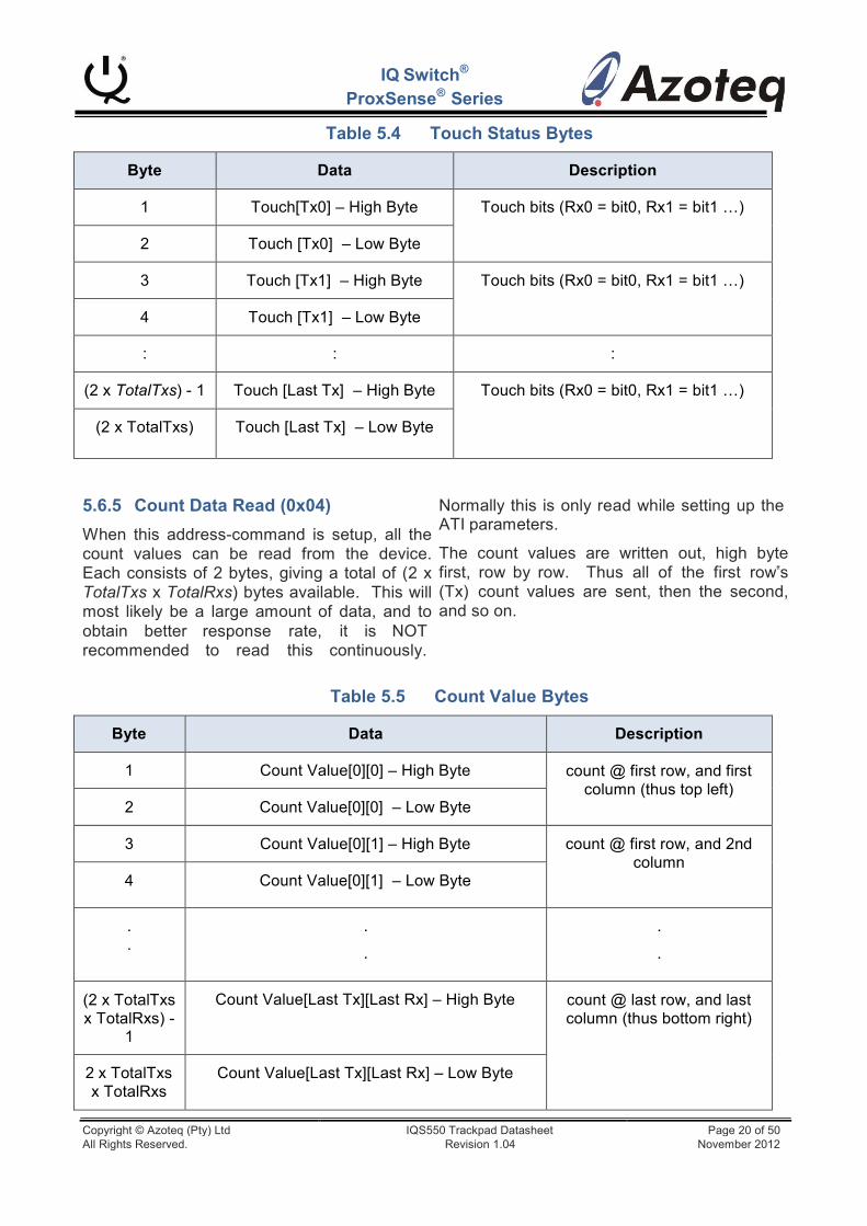
5.6.4 Touch Status Read (0x03)
The touch status of each individual channel can also be retrieved from the IC, exactly the same as the proximity status. After writing the „Touch Status‟ address-command, a read can be performed to obtain the touch bytes.
The touch of each channel found for a corresponding Tx can be obtained from two bytes. This gives a total number of touch bytes of 2 x TotalTxs.
Copyright © Azoteq (Pty) Ltd IQS550 Trackpad Datasheet Page 19 of 50 All Rights Reserved. Revision 1.04 November 2012
IQ Switch®
ProxSense® Series
Table 5.4 Touch Status Bytes
Byte
Data
Description
1
Touch[Tx0] – High Byte
Touch bits (Rx0 = bit0, Rx1 = bit1 …)
2
Touch [Tx0] – Low Byte
3
Touch [Tx1] – High Byte
Touch bits (Rx0 = bit0, Rx1 = bit1 …)
4
Touch [Tx1] – Low Byte
:
:
:
(2 x TotalTxs) - 1
Touch [Last Tx] – High Byte
Touch bits (Rx0 = bit0, Rx1 = bit1 …)
(2 x TotalTxs)
Touch [Last Tx] – Low Byte
5.6.5 Count Data Read (0x04)
When this address-command is setup, all the count values can be read from the device. Each consists of 2 bytes, giving a total of (2 x TotalTxs x TotalRxs) bytes available. This will most likely be a large amount of data, and to obtain better response rate, it is NOT recommended to read this continuously.
Normally this is only read while setting up the ATI parameters.
The count values are written out, high byte first, row by row. Thus all of the first row‟s (Tx) count values are sent, then the second, and so on.
Table 5.5 Count Value Bytes
Byte
Data
Description
1
Count Value[0][0] – High Byte
count @ first row, and first column (thus top left)
2
Count Value[0][0] – Low Byte
3
Count Value[0][1] – High Byte
count @ first row, and 2nd column
4
Count Value[0][1] – Low Byte
.
.
.
.
.
.
(2 x TotalTxs x TotalRxs) -
1
Count Value[Last Tx][Last Rx] – High Byte
count @ last row, and last column (thus bottom right)
2 x TotalTxs x TotalRxs
Count Value[Last Tx][Last Rx] – Low Byte
Copyright © Azoteq (Pty) Ltd IQS550 Trackpad Datasheet Page 20 of 50 All Rights Reserved. Revision 1.04 November 2012
Tx
Port
Tx
Port
Tx0
D0
Tx8
B0
Tx1
D1
Tx9
B1
Tx2
D2
Tx10
B2
Tx3
D3
Tx11
B3
Tx4
D4
Tx12
B4
Tx5
D5
Tx13
B5
Tx6
D6
Tx14
B6
Tx7
D7
~
~
IQ Switch®
ProxSense® Series
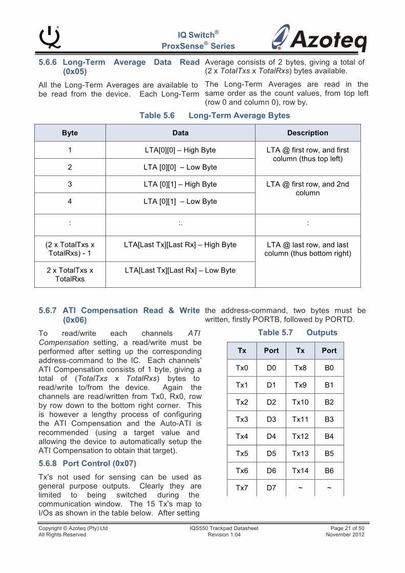
5.6.6 Long-Term Average Data Read (0x05)
All the Long-Term Averages are available to be read from the device. Each Long-Term
Average consists of 2 bytes, giving a total of (2 x TotalTxs x TotalRxs) bytes available.
The Long-Term Averages are read in the same order as the count values, from top left (row 0 and column 0), row by.
Table 5.6 Long-Term Average Bytes
Byte
Data
Description
1
LTA[0][0] – High Byte
LTA @ first row, and first column (thus top left)
2
LTA [0][0] – Low Byte
3
LTA [0][1] – High Byte
LTA @ first row, and 2nd column
4
LTA [0][1] – Low Byte
:
:.
:
(2 x TotalTxs x TotalRxs) - 1
LTA[Last Tx][Last Rx] – High Byte
LTA @ last row, and last column (thus bottom right)
2 x TotalTxs x TotalRxs
LTA[Last Tx][Last Rx] – Low Byte
5.6.7 ATI Compensation Read & Write (0x06)
To read/write each channels ATI Compensation setting, a read/write must be performed after setting up the corresponding address-command to the IC. Each channels‟ ATI Compensation consists of 1 byte, giving a total of (TotalTxs x TotalRxs) bytes to read/write to/from the device. Again the channels are read/written from Tx0, Rx0, row by row down to the bottom right corner. This is however a lengthy process of configuring the ATI Compensation and the Auto-ATI is recommended (using a target value and allowing the device to automatically setup the ATI Compensation to obtain that target).
5.6.8 Port Control (0x07)
Tx‟s not used for sensing can be used as general purpose outputs. Clearly they are limited to being switched during the communication window. The 15 Tx‟s map to I/Os as shown in the table below. After setting
the address-command, two bytes must be written, firstly PORTB, followed by PORTD.
Table 5.7 Outputs
Copyright © Azoteq (Pty) Ltd IQS550 Trackpad Datasheet Page 21 of 50 All Rights Reserved. Revision 1.04 November 2012
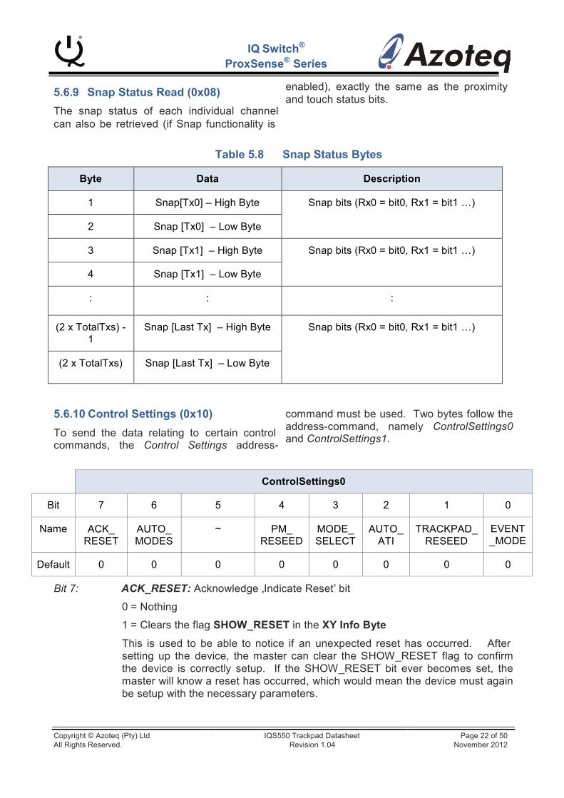
5.6.9 Snap Status Read (0x08)
IQ Switch®
ProxSense® Series
enabled), exactly the same as the proximity and touch status bits.
The snap status of each individual channel can also be retrieved (if Snap functionality is
Table 5.8 Snap Status Bytes
Byte
Data
Description
1
Snap[Tx0] – High Byte
Snap bits (Rx0 = bit0, Rx1 = bit1 …)
2
Snap [Tx0] – Low Byte
3
Snap [Tx1] – High Byte
Snap bits (Rx0 = bit0, Rx1 = bit1 …)
4
Snap [Tx1] – Low Byte
:
:
:
(2 x TotalTxs) - 1
Snap [Last Tx] – High Byte
Snap bits (Rx0 = bit0, Rx1 = bit1 …)
(2 x TotalTxs)
Snap [Last Tx] – Low Byte
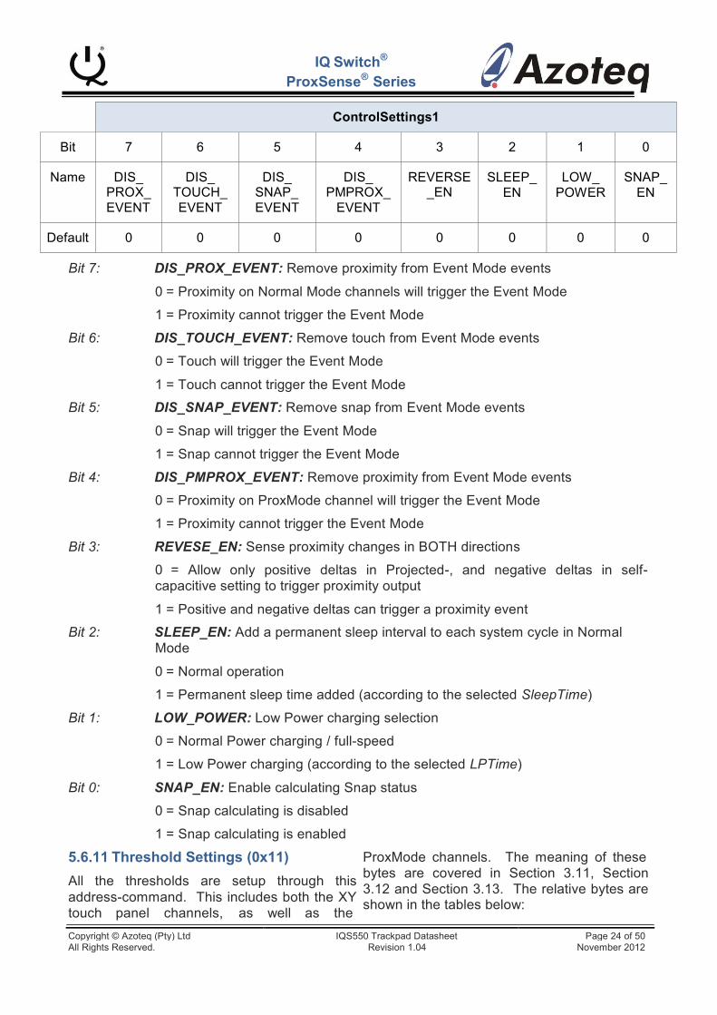
5.6.10 Control Settings (0x10)
To send the data relating to certain control commands, the Control Settings address-
command must be used. Two bytes follow the address-command, namely ControlSettings0 and ControlSettings1.
ControlSettings0
Bit
7
6
5
4
3
2
1
0
Name
ACK_ RESET
AUTO_ MODES
~
PM_ RESEED
MODE_ SELECT
AUTO_ ATI
TRACKPAD_ RESEED
EVENT _MODE
Default
0
0
0
0
0
0
0
0
Bit 7: ACK_RESET: Acknowledge „Indicate Reset‟ bit
0 = Nothing
1 = Clears the flag SHOW_RESET in the XY Info Byte
This is used to be able to notice if an unexpected reset has occurred. After setting up the device, the master can clear the SHOW_RESET flag to confirm the device is correctly setup. If the SHOW_RESET bit ever becomes set, the master will know a reset has occurred, which would mean the device must again be setup with the necessary parameters.
Copyright © Azoteq (Pty) Ltd IQS550 Trackpad Datasheet Page 22 of 50 All Rights Reserved. Revision 1.04 November 2012
IQ Switch®
ProxSense® Series
Bit 6: AUTO_MODES: Automatic mode switching between ProxMode and Normal Charging Mode
0 = Mode is decided by the MODE_SELECT bit
1 = Mode is automatically controlled
Bit 5: Unused
Bit 4: PM_RESEED: Reseed the ProxMode (PM) channel
0 = Do not reseed Long-Term Average
1 = Reseed Long-Term Average with current environment
Note: This only executes (once) after the communication window is completed.
Bit 3: MODE_SELECT: Select charging mode (if AUTO_MODES is not set)
0 = Normal Mode channels charging
1 = ProxMode channel charging
Bit 2: AUTO_ATI: Begin Automatic ATI Compensation routine
0 = No nothing
1 = Begin Auto-ATI routine (affected channels depending on current mode)
The AUTO-ATI bit must be sent ONCE to begin the AUTO-ATI routine. The ATI Compensation will be setup so that each target is close to the respective ATI Target value selected. The bit clears automatically on chip. This bit will then configure the ATI compensation relative to the current mode selected; for example if the system is in ProxMode, then the PM ATI Target will be used, and the ProxMode channel will be configured, similarly the normal mode channels will be configured if this is the current mode.
Note: This routine only executes after the communication window is completed. Also the following communication cycle will occur after the routine is completed.
Bit 1: TRACKPAD_RESEED: Reseed all the Normal Mode channels
0 = No not reseed Long-Term Average
1 = Reseed Long-Term Average with current environment
Note: The RESEED bit for both the trackpad and the ProxMode must be sent only ONCE to reseed the Long-Term Averages, the bit clears automatically on chip. This reseed only executes after the communication window is completed.
Bit 0: EVENT_MODE: Skip communication when no user activity is present
0 = Normal communication / each cycle
1 = Communication aborted until selectable activity (prox/touch/snap) is detected, or the master forces communication
Copyright © Azoteq (Pty) Ltd IQS550 Trackpad Datasheet Page 23 of 50 All Rights Reserved. Revision 1.04 November 2012
IQ Switch®
ProxSense® Series
ControlSettings1
Bit
7
6
5
4
3
2
1
0
Name
DIS_ PROX_ EVENT
DIS_ TOUCH_ EVENT
DIS_ SNAP_ EVENT
DIS_ PMPROX_
EVENT
REVERSE _EN
SLEEP_ EN
LOW_ POWER
SNAP_ EN
Default
0
0
0
0
0
0
0
0
Bit 7: DIS_PROX_EVENT: Remove proximity from Event Mode events
0 = Proximity on Normal Mode channels will trigger the Event Mode
1 = Proximity cannot trigger the Event Mode
Bit 6: DIS_TOUCH_EVENT: Remove touch from Event Mode events
0 = Touch will trigger the Event Mode
1 = Touch cannot trigger the Event Mode
Bit 5: DIS_SNAP_EVENT: Remove snap from Event Mode events
0 = Snap will trigger the Event Mode
1 = Snap cannot trigger the Event Mode
Bit 4: DIS_PMPROX_EVENT: Remove proximity from Event Mode events
0 = Proximity on ProxMode channel will trigger the Event Mode
1 = Proximity cannot trigger the Event Mode
Bit 3: REVESE_EN: Sense proximity changes in BOTH directions
0 = Allow only positive deltas in Projected-, and negative deltas in self- capacitive setting to trigger proximity output
1 = Positive and negative deltas can trigger a proximity event
Bit 2: SLEEP_EN: Add a permanent sleep interval to each system cycle in Normal Mode
0 = Normal operation
1 = Permanent sleep time added (according to the selected SleepTime)
Bit 1: LOW_POWER: Low Power charging selection
0 = Normal Power charging / full-speed
1 = Low Power charging (according to the selected LPTime)
Bit 0: SNAP_EN: Enable calculating Snap status
0 = Snap calculating is disabled
1 = Snap calculating is enabled
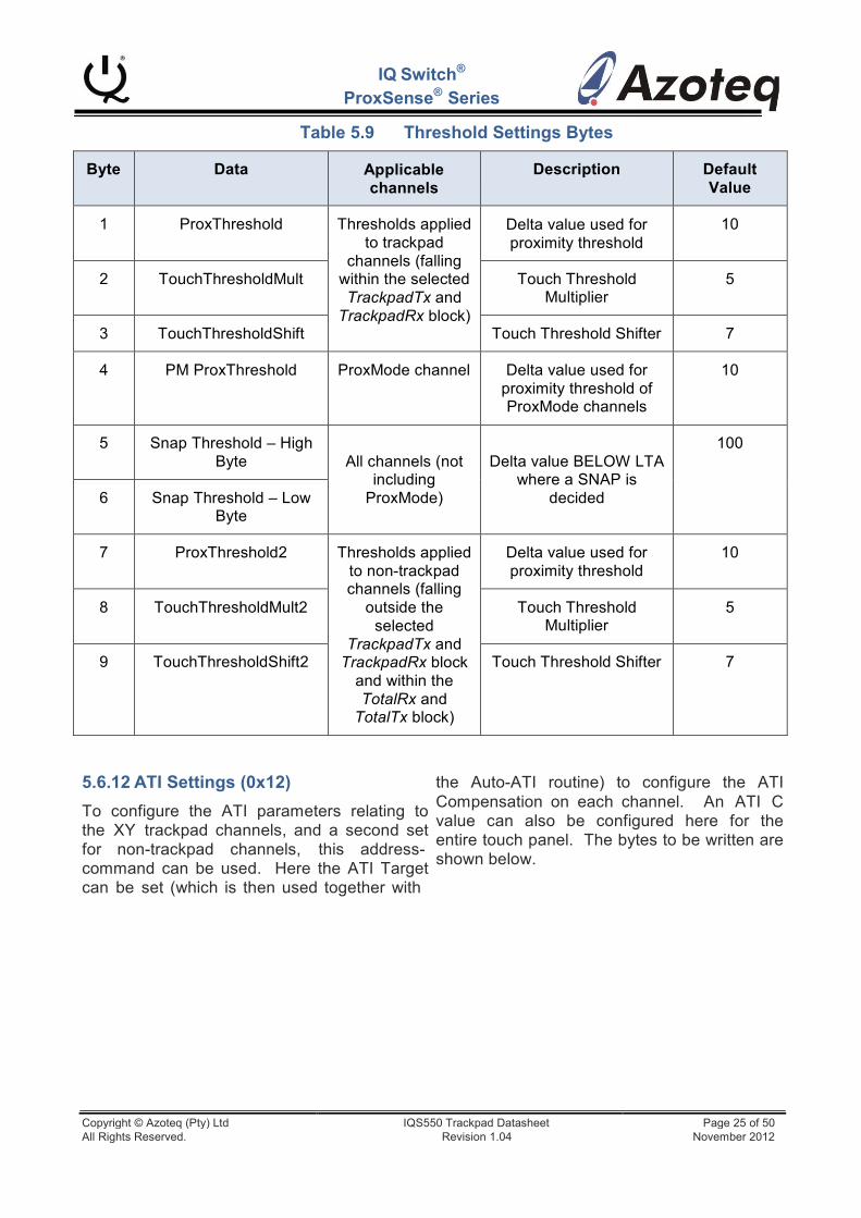
5.6.11 Threshold Settings (0x11)
All the thresholds are setup through this address-command. This includes both the XY touch panel channels, as well as the
ProxMode channels. The meaning of these bytes are covered in Section 3.11, Section 3.12 and Section 3.13. The relative bytes are shown in the tables below:
Copyright © Azoteq (Pty) Ltd IQS550 Trackpad Datasheet Page 24 of 50 All Rights Reserved. Revision 1.04 November 2012
IQ Switch®
ProxSense® Series
Table 5.9 Threshold Settings Bytes
Byte
Data
Applicable channels
Description
Default Value
1
ProxThreshold
Thresholds applied to trackpad
channels (falling within the selected TrackpadTx and
TrackpadRx block)
Delta value used for proximity threshold
10
2
TouchThresholdMult
Touch Threshold Multiplier
5
3
TouchThresholdShift
Touch Threshold Shifter
7
4
PM ProxThreshold
ProxMode channel
Delta value used for proximity threshold of ProxMode channels
10
5
Snap Threshold – High Byte
All channels (not including
ProxMode)
Delta value BELOW LTA where a SNAP is
decided
100
6
Snap Threshold – Low Byte
7
ProxThreshold2
Thresholds applied to non-trackpad channels (falling
outside the selected
TrackpadTx and TrackpadRx block
and within the TotalRx and
TotalTx block)
Delta value used for proximity threshold
10
8
TouchThresholdMult2
Touch Threshold Multiplier
5
9
TouchThresholdShift2
Touch Threshold Shifter
7
5.6.12 ATI Settings (0x12)
To configure the ATI parameters relating to the XY trackpad channels, and a second set for non-trackpad channels, this address- command can be used. Here the ATI Target can be set (which is then used together with
the Auto-ATI routine) to configure the ATI Compensation on each channel. An ATI C value can also be configured here for the entire touch panel. The bytes to be written are shown below.
Copyright © Azoteq (Pty) Ltd IQS550 Trackpad Datasheet Page 25 of 50 All Rights Reserved. Revision 1.04 November 2012
IQ Switch®
ProxSense® Series
Table 5.10 ATI Settings Bytes
Byte
Data
Applicable channels
Description
Default
1
ATI Target – High Byte
ATI settings applied to trackpad
channels (falling within the selected TrackpadTx and
TrackpadRx block)
Automated ATI Target value for ATI
compensation parameter
600
2
ATI Target – Low Byte
3
ATIC
ATI C value (0 to 31 decimal)
0 (values range from 0 to 31
decimal)
4
ATI Target – High Byte
ATI settings applied to non-trackpad channels (falling
outside the selected TrackpadTx and
TrackpadRx block and within the TotalRx and
TotalTx block)
Automated ATI Target value for ATI
compensation parameter
600
5
ATI Target – Low Byte
6
ATIC
ATI C value (0 to 31 decimal)
0 (values range from 0 to 31
decimal)
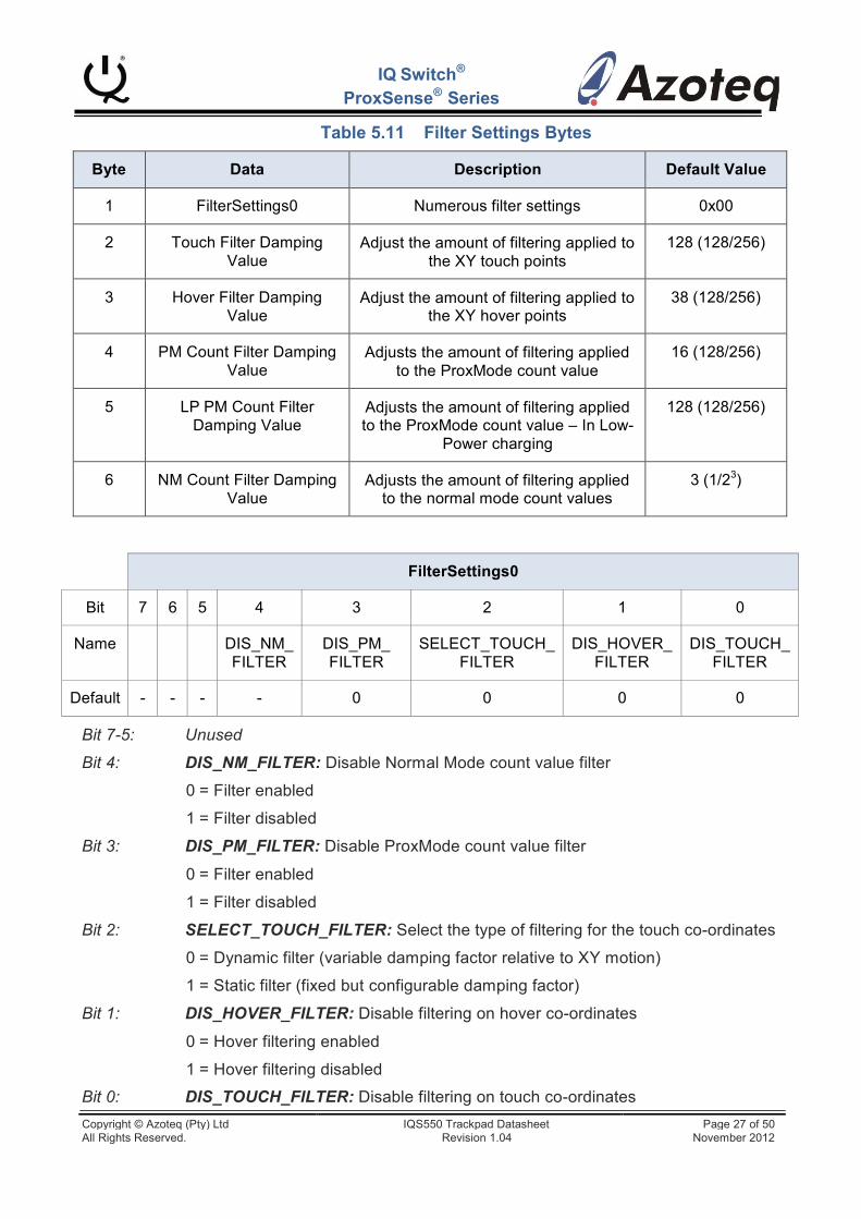
5.6.13 Filter Settings (0x13)
The various settings relating to the on-chip filters can be adjusted / configured here. All
damping parameter for the touch and hover co-ordinate, and ProxMode count filters are used as this value/256. The normal mode
value
these filters can be disabled if not required. count filter damping value is 1/2 . The
Also, the damping factors (amount of filtering) can be adjusted for these independently. This is because the hover requires more filtering, whereby the touch points have either a static or dynamic filter implementation. The
smaller these fractions, the MORE filtering will occur. More filtering provides stable data at the cost of responsiveness. The bytes and definitions are provided.
Copyright © Azoteq (Pty) Ltd IQS550 Trackpad Datasheet Page 26 of 50 All Rights Reserved. Revision 1.04 November 2012
IQ Switch®
ProxSense® Series
Table 5.11 Filter Settings Bytes
Byte
Data
Description
Default Value
1
FilterSettings0
Numerous filter settings
0x00
2
Touch Filter Damping Value
Adjust the amount of filtering applied to the XY touch points
128 (128/256)
3
Hover Filter Damping Value
Adjust the amount of filtering applied to the XY hover points
38 (128/256)
4
PM Count Filter Damping Value
Adjusts the amount of filtering applied to the ProxMode count value
16 (128/256)
5
LP PM Count Filter Damping Value
Adjusts the amount of filtering applied to the ProxMode count value – In Low-
Power charging
128 (128/256)
6
NM Count Filter Damping Value
Adjusts the amount of filtering applied to the normal mode count values
3 (1/23)
FilterSettings0
Bit
7
6
5
4
3
2
1
0
Name
DIS_NM_ FILTER
DIS_PM_ FILTER
SELECT_TOUCH_ FILTER
DIS_HOVER_ FILTER
DIS_TOUCH_ FILTER
Default
-
-
-
-
0
0
0
0
Bit 7-5: Unused
Bit 4: DIS_NM_FILTER: Disable Normal Mode count value filter
0 = Filter enabled
1 = Filter disabled
Bit 3: DIS_PM_FILTER: Disable ProxMode count value filter
0 = Filter enabled
1 = Filter disabled
Bit 2: SELECT_TOUCH_FILTER: Select the type of filtering for the touch co-ordinates
0 = Dynamic filter (variable damping factor relative to XY motion)
1 = Static filter (fixed but configurable damping factor)
Bit 1: DIS_HOVER_FILTER: Disable filtering on hover co-ordinates
0 = Hover filtering enabled
1 = Hover filtering disabled
Bit 0: DIS_TOUCH_FILTER: Disable filtering on touch co-ordinates
Copyright © Azoteq (Pty) Ltd IQS550 Trackpad Datasheet Page 27 of 50 All Rights Reserved. Revision 1.04 November 2012
IQ Switch®
ProxSense® Series
0 = Touch filtering enabled
1 = Touch filtering disabled
5.6.14 Timing Settings (0x14)
On-chip timings can be adjusted here, and are explained below.
Reseed Time
The reseed time is the time that a channel allows a prox/touch to continually be set, before assuming it is a fault condition. Once this time has elapsed, a reseed is forced to correct the condition. In Normal Mode, all the channels (not including the ProxMode channel) are reseeded. For the default value, if a prox/touch is seen anywhere on the touch panel for 40s, a global reseed will be executed to remove this assumed stuck condition. It is recommended to make this timeout quite long, since it is unpleasant to have the device reseed while drawing on the panel. The master can however still send the Reseed command anytime when fault conditions relative to the application are assumed.
When this occurs in ProxMode, only the ProxMode channel is reseeded.
The configurable value works in multiples of 500ms, thus the default value of 80, will select a ReseedTime of 40s.
Comms Timeout
This is a timer that monitors the activity on the I2C bus. If there is no successful read/write this within this time a timeout will occur, and the communication window will close, resuming sensing.
This assists in overcoming any stuck conditions caused by errors on the I2C bus. It can also be used as a RDY timeout, thus if the master cannot always service the communication, and does not mind missing a
cycle‟s data, then the RDY will only be high for the Comms Timeout time, and then it will go low, and the cycle will continue.
Mode Time
This timer is responsible for the timings used when implementing the Automatic Mode control, and also the low-power timings. The value used here is also a multiple of 500ms. For more details see Section 3.4 and Section 3.5
Low-Power Time
Here the low-power timing can be adjusted. Predetermined intervals can be selected here to configure how long the device will sleep between data acquisitions in the Low-Power charging mode. Clearly the longer the sleep time, the lower the power consumption will be, at the expense of response time. Typically the ProxMode channel will be setup to provide a good distance proximity. This will give the device enough time to be up and running before the user interacts with the trackpad channels, even if the LPTime is selected to be reasonably long.
Sleep Time
This is a sleep interval that is permanently added to each cycle in Normal Mode, unlike the Low-Power which is only added under certain conditions (for example if no prox/touch is sensed). This can be used in current sensitive designs, where a rapid response rate is not crucial. For example, if a normal cycle took ~10ms in total, then adding a 10ms SleepTime could almost halve the total current consumption. This would add to any Low-Power timing.
Copyright © Azoteq (Pty) Ltd IQS550 Trackpad Datasheet Page 28 of 50 All Rights Reserved. Revision 1.04 November 2012
IQ Switch®
ProxSense® Series
Table 5.12 Timing Settings Bytes
Byte
Data
Description
Default Value
1
ReseedTime
Stuck prox/touch condition timer
80 (thus 40s)
2
CommsTimeout Timer monitoring the I2C activity
100 (ms)
3
ModeTime
Mode timer (Mode switching, and Low-Power switching)
8 (thus 4s)
4
LPTime
Low-Power timing 8Note1 (~160ms)
5
SleepTime
Permanent sleep timing 3 Note1 (~5ms) Note1: Both of these values are translated to the time interval, as depicted in Table 5.13.
Table 5.13 LPTime and SleepTime Selections
Value
Time
Value
Time
1
1 ms
7
80 ms
2
2 ms
8
160 ms
3
5 ms
9
320 ms
4
10 ms
10
640 ms
5
20 ms
11
1.2 s
6
40 ms
12
2.4 s
13
5 s Note: These are only approximate values, and must not be used for time critical applications.
5.6.15 Channel Setup (0x15)
The amount of Rx‟s and Tx‟s used for trackpad (XY information) purposes, as well as the total Rx and Tx‟s used can be selected. Note that many of the data packets are variable in length relative to how many Rx‟s
and Tx‟s are used. Thus once these are changed, remember that the amount of data available under certain address-commands will then also change.
Copyright © Azoteq (Pty) Ltd IQS550 Trackpad Datasheet Page 29 of 50 All Rights Reserved. Revision 1.04 November 2012
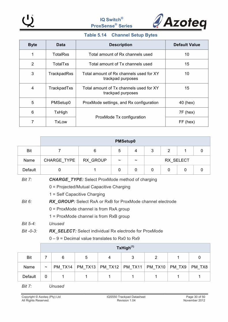
IQ Switch®
ProxSense® Series
Table 5.14 Channel Setup Bytes
Byte
Data
Description
Default Value
1
TotalRxs
Total amount of Rx channels used
10
2
TotalTxs
Total amount of Tx channels used
15
3
TrackpadRxs
Total amount of Rx channels used for XY trackpad purposes
10
4
TrackpadTxs
Total amount of Tx channels used for XY trackpad purposes
15
5
PMSetup0
ProxMode settings, and Rx configuration
40 (hex)
6
TxHigh
ProxMode Tx configuration
7F (hex)
7
TxLow
FF (hex)
PMSetup0
Bit
7
6
5
4
3
2
1
0
Name
CHARGE_TYPE
RX_GROUP
~
~
RX_SELECT
Default
0
1
0
0
0
0
0
0
Bit 7: CHARGE_TYPE: Select ProxMode method of charging
0 = Projected/Mutual Capacitive Charging
1 = Self Capacitive Charging
Bit 6: RX_GROUP: Select RxA or RxB for ProxMode channel electrode
0 = ProxMode channel is from RxA group
1 = ProxMode channel is from RxB group
Bit 5-4: Unused
Bit -0-3: RX_SELECT: Select individual Rx electrode for ProxMode
0 – 9 = Decimal value translates to Rx0 to Rx9
TxHigh(1)
Bit
7
6
5
4
3
2
1
0
Name
~
PM_TX14
PM_TX13
PM_TX12
PM_TX11
PM_TX10
PM_TX9
PM_TX8
Default
0
1
1
1
1
1
1
1
Bit 7: Unused
Copyright © Azoteq (Pty) Ltd IQS550 Trackpad Datasheet Page 30 of 50 All Rights Reserved. Revision 1.04 November 2012
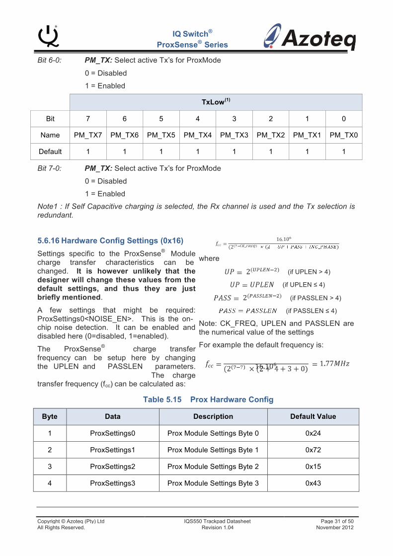
IQ Switch®
ProxSense® Series
Bit 6-0: PM_TX: Select active Tx‟s for ProxMode
0 = Disabled
1 = Enabled
TxLow(1)
Bit
7
6
5
4
3
2
1
0
Name
PM_TX7
PM_TX6
PM_TX5
PM_TX4
PM_TX3
PM_TX2
PM_TX1
PM_TX0
Default
1
1
1
1
1
1
1
1
Bit 7-0: PM_TX: Select active Tx‟s for ProxMode
0 = Disabled
1 = Enabled
Note1 : If Self Capacitive charging is selected, the Rx channel is used and the Tx selection is redundant.
5.6.16 Hardware Config Settings (0x16)
Settings specific to the ProxSense® Module charge transfer characteristics can be changed. It is however unlikely that the designer will change these values from the default settings, and thus they are just briefly mentioned.
A few settings that might be required: ProxSettings0<NOISE_EN>. This is the on-
where
(if UPLEN > 4)
(if UPLEN ≤ 4)
(if PASSLEN > 4)
(if PASSLEN ≤ 4)
chip noise detection. It can be enabled and disabled here (0=disabled, 1=enabled).
The ProxSense® charge transfer frequency can be setup here by changing the UPLEN and PASSLEN parameters. The charge transfer frequency (fcc) can be calculated as:
Note: CK_FREQ, UPLEN and PASSLEN are the numerical value of the settings
For example the default frequency is:
Table 5.15 Prox Hardware Config
Byte
Data
Description
Default Value
1
ProxSettings0
Prox Module Settings Byte 0
0x24
2
ProxSettings1
Prox Module Settings Byte 1
0x72
3
ProxSettings2
Prox Module Settings Byte 2
0x15
4
ProxSettings3
Prox Module Settings Byte 3
0x43
Copyright © Azoteq (Pty) Ltd IQS550 Trackpad Datasheet Page 31 of 50 All Rights Reserved. Revision 1.04 November 2012
IQ Switch®
ProxSense® Series
ProxSettings0
Bit
7
6
5
4
3
2
1
0
Name
~
~
NOISE_EN
~
~
CXVSS
SYNC_EN
SYNC_EDGE
Default
0
0
1
0
0
1
0
0
ProxSettings1
Bit
7
6
5
4
3
2
1
0
Name
MODULE_LP
CK_FREQ<2:0>
~
~
ANA_DEAD
INC_PHASE
Default
0
1
1
1
0
0
1
0
ProxSettings2
Bit
7
6
5
4
3
2
1
0
Name
STBL_1
STBL_0
OP_BIAS1
OP_BIAS0
TRIP3
TRIP2
TRIP1
TRIP0
Default
0
0
0
1
0
1
0
1
ProxSettings3
Bit
7
6
5
4
3
2
1
0
Name
~
UPLEN2
UPLEN1
UPLEN0
~
PASSLEN2
PASSLEN1
PASSLEN0
Default
0
1
0
0
0
0
1
1
5.6.17 Active Channels (0x17)
Here individual channels can be disabled. By clearing the relative bit in the Active Channels
byte a channel disable is achieved. 0 = Disabled 1 = Enabled
Copyright © Azoteq (Pty) Ltd IQS550 Trackpad Datasheet Page 32 of 50 All Rights Reserved. Revision 1.04 November 2012
IQ Switch®
ProxSense® Series
Table 5.16 Active Channel Bytes
Byte
Data
Description
Default
1
ActiveChannels[Tx0] – High Byte
Active Channels bits (Rx0 = bit0, Rx1 = bit1
…)
0x3FF
2
ActiveChannels [Tx0] – Low Byte
3
ActiveChannels [Tx1] – High Byte
Active Channels bits (Rx0 = bit0, Rx1 = bit1
…)
0x3FF
4
ActiveChannels [Tx1] – Low Byte
:
:
:
0x3FF
(2 x TotalTxs) - 1
ActiveChannels [Last Tx] – High Byte
Active Channels bits (Rx0 = bit0, Rx1 = bit1
…)
0x3FF
(2 x TotalTxs)
ActiveChannels [Last Tx] – Low Byte
5.6.18 Debounce Settings
The debounce parameters of the channel outputs can be configured here.
Table 5.17 Debounce Value Bytes
Byte
Data
Description
Default
1
ProxDb
Proximity debounce values
0x44
(Db = 4)
2
TouchSnapDb
Touch and snap debounce values
0x44 (Touch
db = 0
Snap db = 1)
ProxDb
Bit
7
6
5
4
3
2
1
0
Name
Prox Set Debounce
Prox Clear Debounce
Default
0
1
0
0
0
1
0
0
Copyright © Azoteq (Pty) Ltd IQS550 Trackpad Datasheet Page 33 of 50 All Rights Reserved. Revision 1.04 November 2012
IQ Switch®
ProxSense® Series
TouchSnapDb
Bit
7
6
5
4
3
2
1
0
Name
Click Set Debounce
Touch Set Debounce
Click Clear Debounce
Touch Clear Debounce
Default
0
1
0
0
0
1
0
0
5.6.19 ProxMode Proximity Status (0x20)
The proximity of the ProxMode channel can be obtained here.
Table 5.18 PM Proximity Status Bytes
Byte
Data
Description
1
PM Prox Byte
0 = No Prox / 1 = ProxMode Channel Prox
5.6.20 ProxMode Count Data Read (0x21)
When this address-command is setup, the count value for the ProxMode channel can be read.
The count value consists of 2 bytes. Normally this is only read while setting up the ATI parameters
Table 5.19 ProxMode Count Values
Byte
Data
Description
1
PM Count Value – High Byte
ProxMode count value for self capacitive prox channel
2
PM Count Value – Low Byte
5.6.21 ProxMode Long-Term Average Read (0x22)
When this address-command is the Long- Term-Average for the ProxMode channel can
be read. The Long-Term Average again consists of 2 bytes.
Table 5.20 PM Long-Term Average Bytes
Byte
Data
Description
1
PM Long-Term Average – High Byte
ProxMode Long-Term Average for self capacitive
prox channel
2
PM Long-Term Average – Low Byte
Copyright © Azoteq (Pty) Ltd IQS550 Trackpad Datasheet Page 34 of 50 All Rights Reserved. Revision 1.04 November 2012
IQ Switch®
ProxSense® Series
5.6.22 ProxMode ATI Compensation Read/Write (0x23)
To read or write the ProxMode channels‟ ATI Compensation value, a read/write must be performed after setting up the corresponding address-command. Configuring the ATI Compensation manually is however a lengthy process and the Auto-ATI routine is recommended. The ATI Compensation is a single byte.
5.6.23 ProxMode ATI Settings (0x24)
To configure the ProxMode ATI parameters, this address-command can be used. Here the ATI target can be configured (which is then used together with the Auto-ATI routine) to configure the ATI Compensation on the ProxMode channel. An ATI C value can also be configured for the ProxMode channel. The bytes to be written are shown below.
Table 5.21 ATI Settings Bytes
Byte
Data
Description
Default Value
1
PM ATI Target – High Byte
Automated ATI Target Value for ATI
Compensation parameter
500
2
PM ATI Target – Low Byte
3
PM ATIC
ATI C value
0 (values from 0 to 31)
Copyright © Azoteq (Pty) Ltd IQS550 Trackpad Datasheet Page 35 of 50 All Rights Reserved. Revision 1.04 November 2012
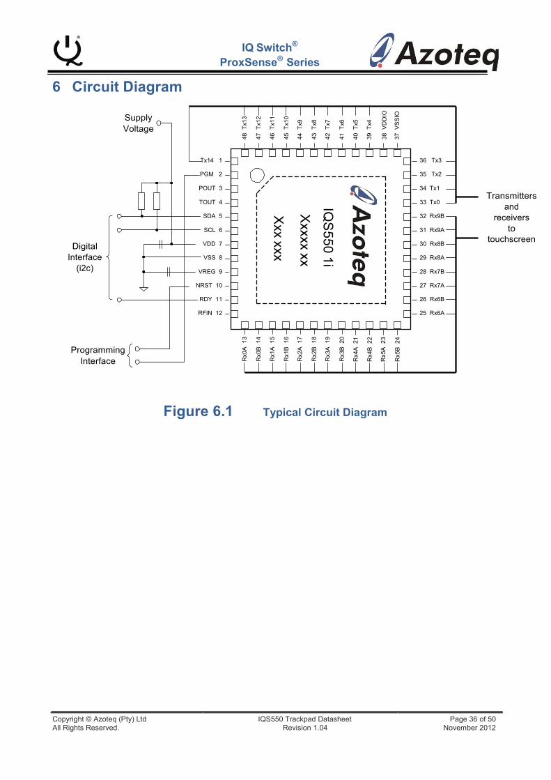
IQS
550 1i X
xxxx xx
Xxx xxx
Rx0
A 1
3 48
Tx1
3
Rx0
B 1
4 47
Tx1
2
Rx1
A 1
5 46
Tx1
1
Rx1
B 1
6 45
Tx1
0
Rx2
A 1
7 44
Tx9
Rx2
B 1
8 43
Tx8
Rx3
A 1
9 42
Tx7
Rx3
B 2
0 41
Tx6
40 T
x5
Rx4
A 2
1
39 T
x4
Rx4
B 2
2
Rx5
A 2
3 38
VD
DIO
37 V
SS
IO
Rx5
B 2
4
6 Circuit Diagram
IQ Switch®
ProxSense® Series
Supply Voltage
Tx14 1
PGM 2
36 Tx3 35 Tx2
Digital Interface
(i2c)
POUT 3
TOUT 4
SDA 5
SCL 6
VDD 7
VSS 8
VREG 9
NRST 10
RDY 11 RFIN 12
34 Tx1 33 Tx0 32 Rx9B 31 Rx9A 30 Rx8B 29 Rx8A 28 Rx7B 27 Rx7A 26 Rx6B 25 Rx6A
Transmitters
and receivers
to touchscreen
Programming Interface
Figure 6.1 Typical Circuit Diagram
Copyright © Azoteq (Pty) Ltd IQS550 Trackpad Datasheet Page 36 of 50 All Rights Reserved. Revision 1.04 November 2012
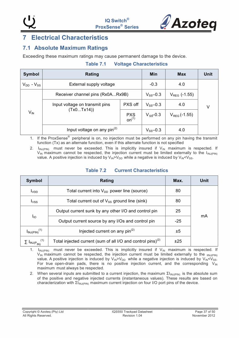
Symbol
Rating
Min
Max
Unit
VDD - VSS
External supply voltage
-0.3
4.0
V
VIN
Receiver channel pins (Rx0A...Rx9B)
VSS–0.3
VREG (-1.55)
Input voltage on transmit pins (Tx0...Tx14))
PXS off
VSS–0.3
4.0
PXS on(1)
V –0.3
V (-1.55)
Input voltage on any pin(2)
VSS–0.3
4.0
IQ Switch®
ProxSense® Series
7 Electrical Characteristics
7.1 Absolute Maximum Ratings
Exceeding these maximum ratings may cause permanent damage to the device.
Table 7.1 Voltage Characteristics
SS REG
1. If the ProxSense® peripheral is on, no injection must be performed on any pin having the transmit function (Tx) as an alternate function, even if this alternate function is not specified
2. IINJ(PIN) must never be exceeded. This is implicitly insured if VIN maximum is respected. If VIN maximum cannot be respected, the injection current must be limited externally to the IINJ(PIN) value. A positive injection is induced by VIN>VDD while a negative is induced by VIN<VSS.
Table 7.2 Current Characteristics
Symbol
Rating
Max.
Unit
IVDD
Total current into VDD power line (source)
80
mA
IVSS
Total current out of VSS ground line (sink)
80
IIO
Output current sunk by any other I/O and control pin
25
Output current source by any I/Os and control pin
-25
IINJ(PIN)(1) Injected current on any pin(2)
±5 ∑ IINJ(P
(1) IN) Total injected current (sum of all I/O and control pins)(2)
±25
1. IINJ(PIN) must never be exceeded. This is implicitly insured if VIN maximum is respected. If VIN maximum cannot be respected, the injection current must be limited externally to the IINJ(PIN) value. A positive injection is induced by VIN>VDD while a negative injection is induced by VIN<VSS. For true open-drain pads, there is no positive injection current, and the corresponding VIN maximum must always be respected.
2. When several inputs are submitted to a current injection, the maximum ΣIINJ(PIN) is the absolute sum of the positive and negative injected currents (instantaneous values). These results are based on characterization with ΣIINJ(PIN) maximum current injection on four I/O port pins of the device.
Copyright © Azoteq (Pty) Ltd IQS550 Trackpad Datasheet Page 37 of 50 All Rights Reserved. Revision 1.04 November 2012
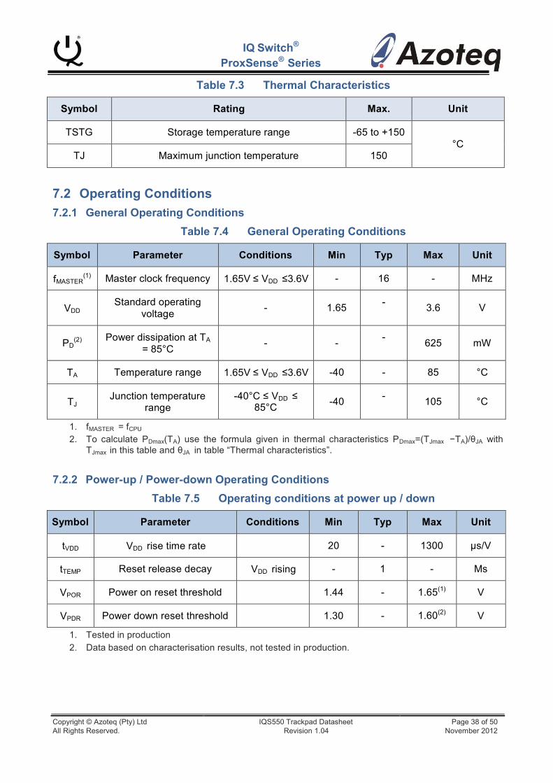
IQ Switch®
ProxSense® Series
Table 7.3 Thermal Characteristics
Symbol
Rating
Max.
Unit
TSTG
Storage temperature range
-65 to +150
°C
TJ
Maximum junction temperature
150
7.2 Operating Conditions
7.2.1 General Operating Conditions
Table 7.4 General Operating Conditions
Symbol
Parameter
Conditions
Min
Typ
Max
Unit
fMASTER(1)
Master clock frequency
1.65V ≤ VDD ≤3.6V
-
16
-
MHz
VDD
Standard operating voltage
-
1.65
- 3.6
V
PD
(2)
Power dissipation at TA
= 85°C
-
-
- 625
mW
TA
Temperature range
1.65V ≤ VDD ≤3.6V
-40
-
85
°C
TJ
Junction temperature range
-40°C ≤ VDD ≤ 85°C
-40
- 105
°C
1. fMASTER = fCPU
2. To calculate PDmax(TA) use the formula given in thermal characteristics PDmax=(TJmax −TA)/θJA with TJmax in this table and θJA in table “Thermal characteristics”.
7.2.2 Power-up / Power-down Operating Conditions
Table 7.5 Operating conditions at power up / down
Symbol
Parameter
Conditions
Min
Typ
Max
Unit
tVDD
VDD rise time rate
20
-
1300
µs/V
tTEMP
Reset release decay
VDD rising
-
1
-
Ms
VPOR
Power on reset threshold
1.44
- 1.65(1)
V
VPDR
Power down reset threshold
1.30
- 1.60(2)
V
1. Tested in production 2. Data based on characterisation results, not tested in production.
Copyright © Azoteq (Pty) Ltd IQS550 Trackpad Datasheet Page 38 of 50 All Rights Reserved. Revision 1.04 November 2012
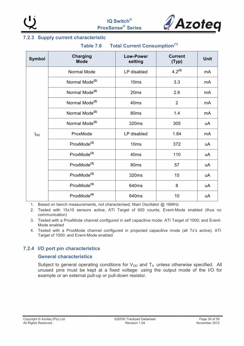
IQ Switch®
ProxSense® Series
7.2.3 Supply current characteristic
Table 7.6 Total Current Consumption(1)
Symbol
Charging Mode
Low-Power setting
Current (Typ)
Unit
IDD
Normal Mode
LP disabled 4.2(3)
mA
Normal Mode(2)
10ms
3.3
mA
Normal Mode(2)
20ms
2.6
mA
Normal Mode(2)
40ms
2
mA
Normal Mode(2)
80ms
1.4
mA
Normal Mode(2)
320ms
305
uA
ProxMode
LP disabled
1.84
mA
ProxMode(3)
10ms
372
uA
ProxMode(3)
40ms
110
uA
ProxMode(3)
80ms
57
uA
ProxMode(3)
320ms
15
uA
ProxMode(3)
640ms
8
uA
ProxMode(4)
640ms
10
uA
1. Based on bench measurements, not characterised; Main Oscillator @ 16MHz 2. Tested with 15x10 sensors active; ATI Target of 600 counts; Event-Mode enabled (thus no
communication) 3. Tested with a ProxMode channel configured in self capacitive mode; ATI Target of 1000; and Event-
Mode enabled 4. Tested with a ProxMode channel configured in projected capacitive mode (all Tx‟s active); ATI
Target of 1000; and Event-Mode enabled
7.2.4 I/O port pin characteristics
General characteristics
Subject to general operating conditions for VDD and TA unless otherwise specified. All unused pins must be kept at a fixed voltage: using the output mode of the I/O for example or an external pull-up or pull-down resistor.
Copyright © Azoteq (Pty) Ltd IQS550 Trackpad Datasheet Page 39 of 50 All Rights Reserved. Revision 1.04 November 2012
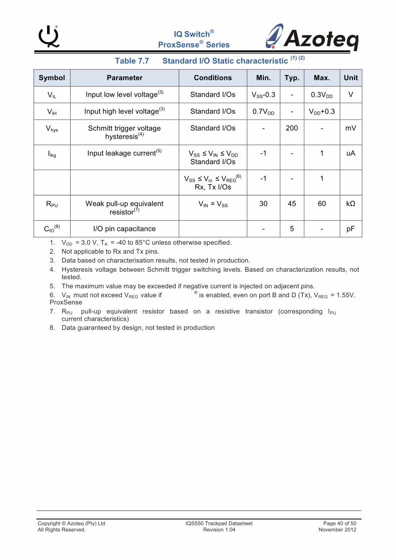
IQ Switch®
ProxSense® Series
Table 7.7 Standard I/O Static characteristic (1) (2)
Symbol
Parameter
Conditions
Min.
Typ.
Max.
Unit
VIL Input low level voltage(3)
Standard I/Os
VSS-0.3
-
0.3VDD
V
VIH Input high level voltage(3)
Standard I/Os
0.7VDD
-
VDD+0.3
Vhys
Schmitt trigger voltage hysteresis(4)
Standard I/Os
-
200
-
mV
IIkg Input leakage current(5)
VSS ≤ VIN ≤ VDD Standard I/Os
-1
-
1
uA
(6) VSS ≤ Vin ≤ VREG Rx, Tx I/Os
-1
-
1
RPU
Weak pull-up equivalent resistor(7)
VIN = VSS
30
45
60
kΩ
CIO(8)
I/O pin capacitance
-
5
-
pF
1. VDD = 3.0 V, TA = -40 to 85°C unless otherwise specified. 2. Not applicable to Rx and Tx pins. 3. Data based on characterisation results, not tested in production. 4. Hysteresis voltage between Schmitt trigger switching levels. Based on characterization results, not
tested. 5. The maximum value may be exceeded if negative current is injected on adjacent pins.
® 6. VIN must not exceed VREG value if ProxSense
is enabled, even on port B and D (Tx), VREG = 1.55V.
7. RPU pull-up equivalent resistor based on a resistive transistor (corresponding IPU current characteristics)
8. Data guaranteed by design, not tested in production
Copyright © Azoteq (Pty) Ltd IQS550 Trackpad Datasheet Page 40 of 50 All Rights Reserved. Revision 1.04 November 2012
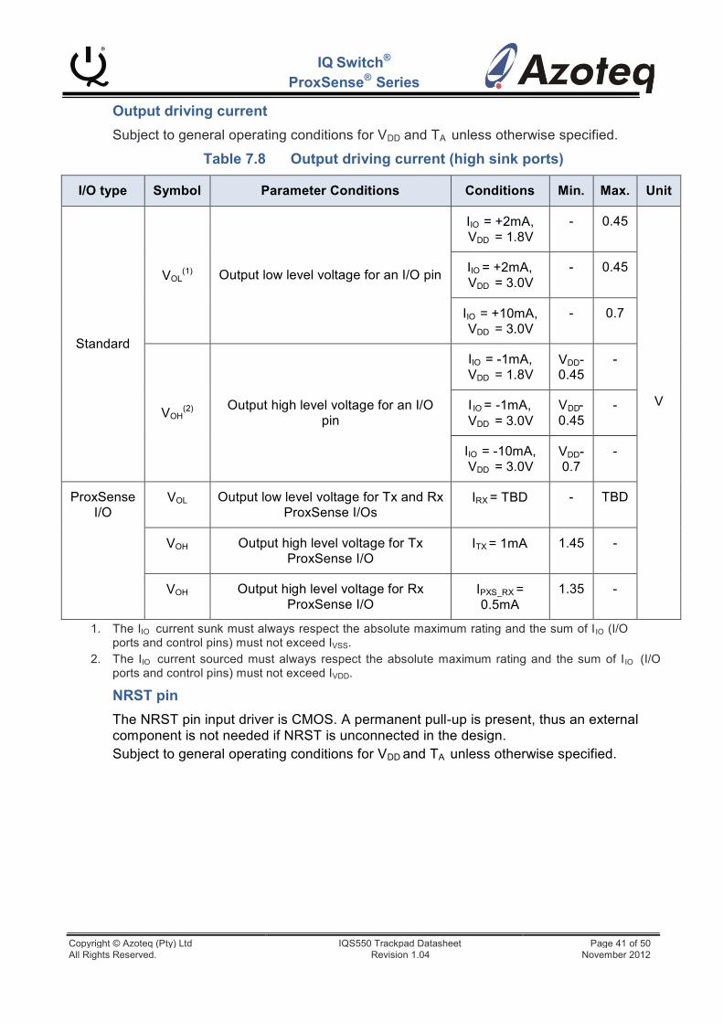
I/O type
Symbol
Parameter Conditions
Conditions
Min.
Max.
Unit
Standard
(1) VOL
Output low level voltage for an I/O pin
IIO = +2mA, VDD = 1.8V
-
0.45
V
IIO = +2mA, VDD = 3.0V
-
0.45
IIO = +10mA, VDD = 3.0V
-
0.7
VOH(2)
Output high level voltage for an I/O pin
IIO = -1mA, VDD = 1.8V
VDD- 0.45
-
I = -1mA, VDD = 3.0V
V - 0.45
-
IIO = -10mA, VDD = 3.0V
VDD- 0.7
-
ProxSense I/O
VOL
Output low level voltage for Tx and Rx ProxSense I/Os
IRX = TBD
-
TBD
VOH
Output high level voltage for Tx ProxSense I/O
ITX = 1mA
1.45
-
VOH
Output high level voltage for Rx ProxSense I/O
IPXS_RX = 0.5mA
1.35
-
IQ Switch®
ProxSense® Series
Output driving current
Subject to general operating conditions for VDD and TA unless otherwise specified.
Table 7.8 Output driving current (high sink ports)
IO DD
1. The IIO current sunk must always respect the absolute maximum rating and the sum of IIO (I/O ports and control pins) must not exceed IVSS.
2. The IIO current sourced must always respect the absolute maximum rating and the sum of IIO (I/O ports and control pins) must not exceed IVDD.
NRST pin
The NRST pin input driver is CMOS. A permanent pull-up is present, thus an external component is not needed if NRST is unconnected in the design. Subject to general operating conditions for VDD and TA unless otherwise specified.
Copyright © Azoteq (Pty) Ltd IQS550 Trackpad Datasheet Page 41 of 50 All Rights Reserved. Revision 1.04 November 2012
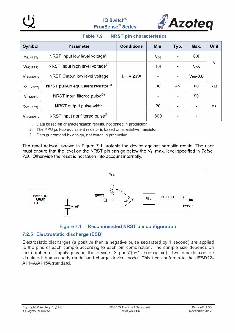
IQ Switch®
ProxSense® Series
Table 7.9 NRST pin characteristics
Symbol
Parameter
Conditions
Min.
Typ.
Max.
Unit
VIL(NRST) NRST Input low level voltage(1)
VSS
-
0.8
V
VIH(NRST) NRST Input high level voltage(1)
1.4
-
VDD
VOL(NRST)
NRST Output low level voltage
IOL = 2mA
-
-
VDD-0.8
RPU(NRST) NRST pull-up equivalent resistor(2)
30
45
60
kΩ
VF(NRST) NRST input filtered pulse(3)
-
-
50
ns
tOP(NRST)
NRST output pulse width
20
-
-
VNF(NRST) NRST input not filtered pulse(3)
300
-
-
1. Data based on characterization results, not tested in production. 2. The RPU pull-up equivalent resistor is based on a resistive transistor. 3. Data guaranteed by design, not tested in production.
The reset network shown in Figure 7.1 protects the device against parasitic resets. The user must ensure that the level on the NRST pin can go below the VIL max. level specified in Table 7.9. Otherwise the reset is not taken into account internally.
Figure 7.1 Recommended NRST pin configuration
7.2.5 Electrostatic discharge (ESD)
Electrostatic discharges (a positive then a negative pulse separated by 1 second) are applied to the pins of each sample according to each pin combination. The sample size depends on the number of supply pins in the device (3 parts*(n+1) supply pin). Two models can be simulated: human body model and charge device model. This test conforms to the JESD22- A114A/A115A standard.
Copyright © Azoteq (Pty) Ltd IQS550 Trackpad Datasheet Page 42 of 50 All Rights Reserved. Revision 1.04 November 2012

IQ Switch®
ProxSense® Series
Table 7.10 ESD Absolute Maximum Ratings
Symbol
Ratings
Conditions
Max Value
Unit
VESD(HBM)
Electrostatic discharge voltage
(human body model)
TA = +25 °C
2000(2)
V
VESD(CDM)
Electrostatic discharge voltage
(charge device model)
1000
1. Data based on characterisation results, not tested in production. 2. Device sustained up to 3000 V during ESD trials.
7.2.6 Thermal characteristics
The maximum chip junction temperature (TJmax) must never exceed the values given in Table 7.4.
The maximum chip-junction temperature, TJmax, in degrees Celsius, may be calculated using the following equation:
Where:
TJmax = TAmax + (PDmax x θJA)
● TAmax is the maximum ambient temperature in °C
● θJA is the package junction-to-ambient thermal resistance in °C/W
● PDmax is the sum of PINTmax and PI/Omax (PDmax = PINTmax + PI/Omax)
● PINTmax is the product of IDD and VDD, expressed in watts. This is the maximum chip internal power.
● PI/Omax represents the maximum power dissipation on output pins where: PI/Omax = Σ (VOL*IOL) + Σ((VDD−VOH)*IOH), taking into account the actual VOL/IOL and VOH/IOH of the I/Os at low and high level in the application.
Table 7.11 Thermal characteristics(1)
Symbol
Parameter
Value
Unit
ΘJA
Thermal resistance junction ambient
32
°C/W
1. Thermal resistances are based on JEDEC JESD51-2 with 4-layer PCB in a natural convection environment.
Copyright © Azoteq (Pty) Ltd IQS550 Trackpad Datasheet Page 43 of 50 All Rights Reserved. Revision 1.04 November 2012
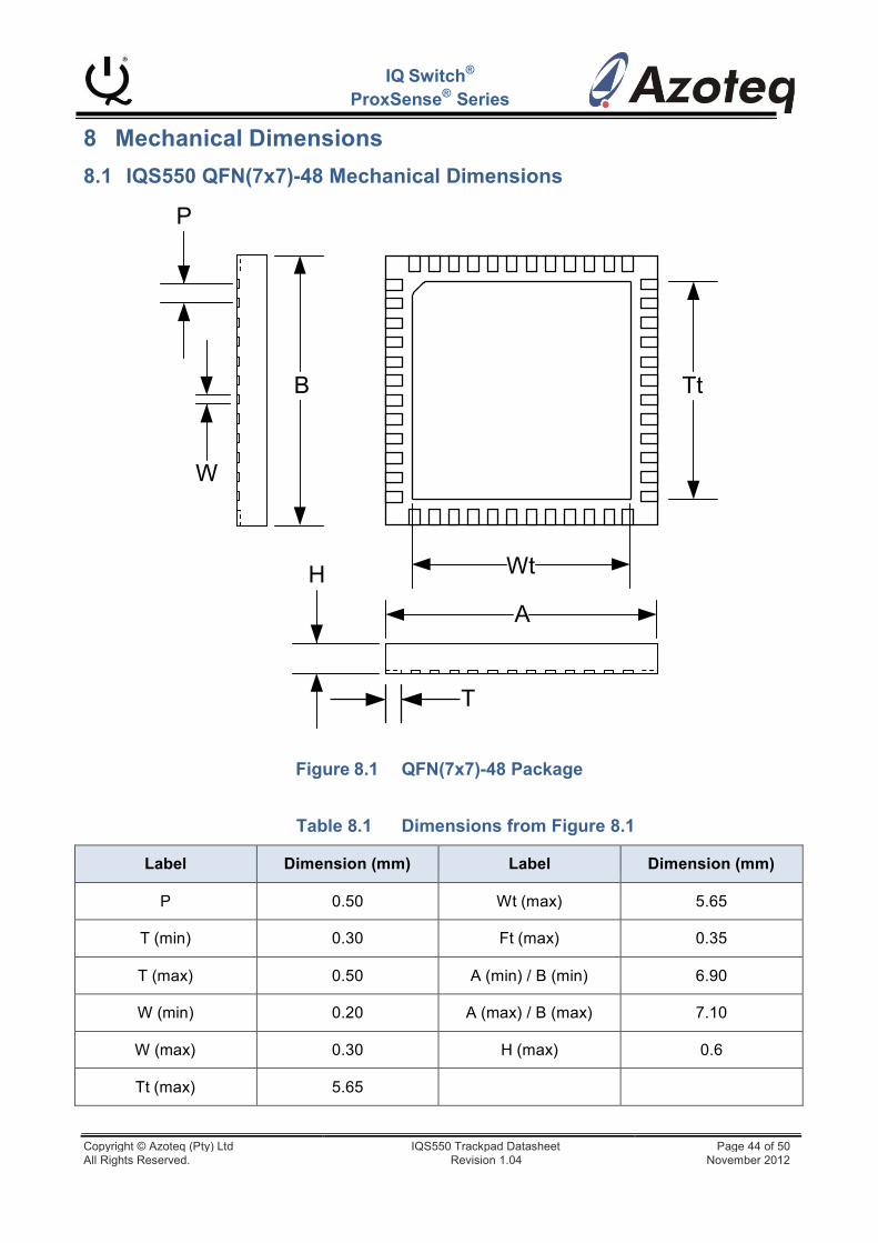
IQ Switch®
ProxSense® Series
8 Mechanical Dimensions
8.1 IQS550 QFN(7x7)-48 Mechanical Dimensions
P
B Tt
W
H Wt
A
T
Figure 8.1 QFN(7x7)-48 Package
Table 8.1 Dimensions from Figure 8.1
Label
Dimension (mm)
Label
Dimension (mm)
P
0.50
Wt (max)
5.65
T (min)
0.30
Ft (max)
0.35
T (max)
0.50
A (min) / B (min)
6.90
W (min)
0.20
A (max) / B (max)
7.10
W (max)
0.30
H (max)
0.6
Tt (max)
5.65
Copyright © Azoteq (Pty) Ltd IQS550 Trackpad Datasheet Page 44 of 50 All Rights Reserved. Revision 1.04 November 2012

Y2
IQ Switch®
ProxSense® Series
8.2 IQS550 Landing Pad Layout
Y1 C2
X2
48 47 46 45 44 43 42 41 40 39 38 37
1
2
3
X1 4
5
6
7
8
9
10
11
12
36
35
34
33
32
31 49
30
29
28
27
26
25
13 14 15 16 17 18 19 20 21 22 23 24
C1
Figure 8.2 QFN(7x7)-48 Footprint
Table 8.2 Dimensions from Figure 8.2
Label
Dimension (mm)
Label
Dimension (mm)
C1
7.00
C2
7.00
Y1
0.80
Y2
5.65
X1
0.30
X2
5.65
*Note: Pin 49 = Vss
Copyright © Azoteq (Pty) Ltd IQS550 Trackpad Datasheet Page 45 of 50 All Rights Reserved. Revision 1.04 November 2012

9 Device Marking
IQ Switch®
ProxSense® Series
A = IC Name B = Assembly Plant C = Internal use D = Internal use E = Country of Origin F = Assembly Year G = Assembly Week H = Dot – Pin1 reference I = Internal use J = Design Revision
10 Ordering Information
Order quantities will be subject to multiples of a full reel.
For large orders, Azoteq can provide pre-configured devices.
IQS550 QN R
IC NAME BULK PACKAGING
PACKAGE TYPE
IC NAME IQS550 = IQS550 PACKAGE TYPE
BULK PACKAGING QN
R =
= QFN(7x7)-48
Reel (2500pc/reel)
Copyright © Azoteq (Pty) Ltd IQS550 Trackpad Datasheet Page 46 of 50 All Rights Reserved. Revision 1.04 November 2012
Changes:
Release v1.00
IQS550 datasheet released Release v1.01
IQ Switch®
ProxSense® Series
Removed all communication timeout information (RDY timeout) Add normal mode sample filtering and its relative settings Changed naming of Low Power sleep time to just Low-‐Power timing Added SleepTime (permanent sleep interval during every cycle) Removed Main Oscillator settings, system now only 16MHz, with addition of permanent Sleep to decrease current consumption.
Release v1.02 (Changes implemented to reflect firmware release 54 changes) Software changes not affecting this document:
o Fixed a bit error in XY calculations (only observed with new panels with very high sensor gain)
o Changed on-‐chip i2c from software to hardware implementation o Fixed multiple co-‐ordinates shown with a single touch on Rx0/Tx0 channel o Updated to libraries o Added timer updating/compensating for sleep periods. o Updated reseed in AutoATI routine o Changed XY calculations to only use positive delta’s o Updated PM reseed to use the filtered value – if filter enabled o Separate reseed counters of Normal Mode and Prox Mode implemented, no longer
just one global reseed counter. But they use the same setting. Changed the terminology ‘Click’ to ‘Snap’ (to remove confusion with mouse ‘clicks’ also implemented on trackpads) Added SYNC settings to ProxSettings0 Support timing up till 5s (Updated Table 5.13) Added selectable debounce values (Added Section 3.14, Updated Table 5.1, Added Section 5.6.18) Updated Figure 3.2 Added second set of settings for non-‐trackpad channels. ATI and threshold options added. (Update Section 3.9, Section 4.3, Section 5.6.12, Table 5.9, Section 3.11, Section 3.12)
Added an automatic update of the Normal Mode channels when the mode is set to Auto. (since it could be possible that system stays in ProxMode for long periods of time, the LTA’s of the NormalMode must be kept up to date). Updated Section 3.4.
Added selectable ‘reverse’ sensing to ProxMode channel. Updated Section 3.11 and Section 5.6.10.
Added selectable Events to trigger the EventMode operation. Updated Section 4.1 and Section 5.6.10. Updated Section 4.6. Added i2c comms timeout, Updated Section 5.6.14. Updated Figure 2.1 and Figure 6.1
Copyright © Azoteq (Pty) Ltd IQS550 Trackpad Datasheet Page 47 of 50 All Rights Reserved. Revision 1.04 November 2012

IQ Switch®
ProxSense® Series
Release v1.03 Terminology update and minor fixes Changed Pretoria office address Updated Patent information
Release v1.04
Changes Product and Project Number (2 bytes each). Also Split version number into a Major Revision, and Minor Revision number (1 byte each). Updated Section 5.6.1.
Reduced NO_OF_FINGERS in XYInfoByte from 4 to 3 bits. And added a global Snap status to the available bit. Updated Section 5.6.2.
Added I2C read rights to all the settings, so that designer can read back settings for confirmation. Updated Table 5.1.
Added ProxMode layout suggestion to Section 3.3 (added Figure 3.1)
Copyright © Azoteq (Pty) Ltd IQS550 Trackpad Datasheet Page 48 of 50 All Rights Reserved. Revision 1.04 November 2012

IQ Switch®
ProxSense® Series
PRETORIA OFFICE
Physical Address
Menlyn Square, East Block, First Floor
116 Lois, C/O Gobie Avenue
Menlyn
Pretoria
0181
Republic of South Africa
Tel: +27 12 361 9338
Fax: +27 12 361 3784
PAARL OFFICE
Physical Address
109 Main Street
Paarl
7646
Western Cape
Republic of South Africa Tel: +27 21 863 0033
Fax: +27 21 863 1512
Please visit www.azoteq.com for a full portfolio of the ProxSenseTM
Capacitive Sensors, Datasheets, Application Notes and Evaluation Kits available.
The following patents relate to the device or usage of the device: US 6,249,089 B1, US 6,621,225 B2, US 6,650,066 B2, US 6,952,084 B2, US 6,984,900 B1, US 7,084,526 B2, US 7,084,531 B2, US 7,119,459 B2, US 7,265,494 B2, US 7,291,940 B2, US 7,329,970 B2, US 7,336,037 B2, US 7,443,101 B2, US 7,466,040 B2, US 7,498,749 B2, US 7,528,508 B2, US 7,755,219 B2, US 7,772,781, US 7,781,980 B2, US 7,915,765 B2, EP 1 120 018 B1, EP 1 206 168 B1, EP 1 308 913 B1, EP 1 530 178 B1, ZL 99 8 14357.X, AUS 761094
IQ Switch®, ProxSense®, LightSense™, AirButton®, SwipeSwitchTM and
the logo are trademarks of Azoteq.
The information in this Datasheet is believed to be accurate at the time of publication. Azoteq assumes no liability arising from the use of the information or the product. The applications mentioned herein are used solely for the purpose of illustration and Azoteq makes no warranty or representation that such applications will be suitable without further modification, nor recommends the use of its products for application that may present a risk to human life due to malfunction or otherwise. Azoteq products are not authorized for use as critical components in life support devices or systems. No licenses to patents are granted, implicitly or otherwise, under any intellectual property rights. Azoteq reserves the right to alter its products without prior notification. For the most up-to-date information, please refer to www.azoteq.com.
WWW.AZOTEQ.COM [email protected]
Copyright © Azoteq (Pty) Ltd IQS550 Trackpad Datasheet Page 49 of 50 All Rights Reserved. Revision 1.04 November 2012

IQ Switch®
ProxSense® Series
Copyright © Azoteq (Pty) Ltd IQS550 Trackpad Datasheet Page 50 of 50 All Rights Reserved. Revision 1.04 November 2012