Embed Size (px)
Citation preview
IQBDA3S SECTION 36
IQBDA3SOPS 160604 www.snellwilcox.com Version 1 Issue 6 36.1
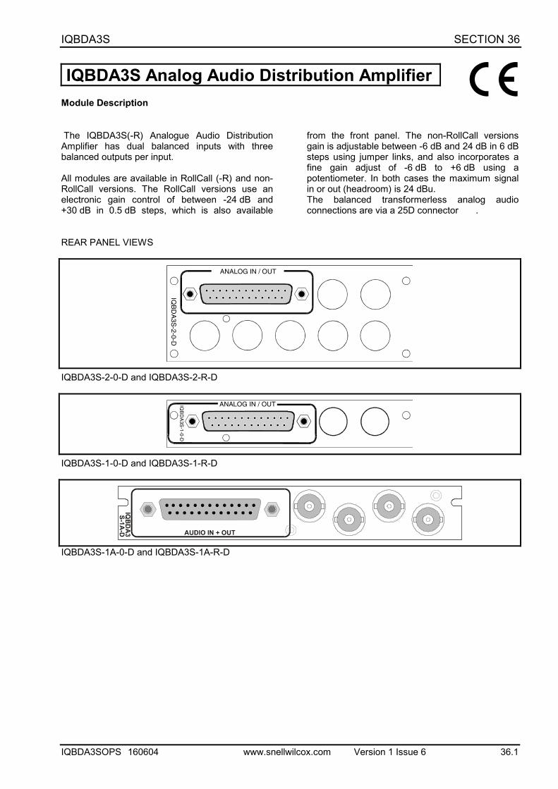
IQBDA3S Analog Audio Distribution AmplifierModule Description
The IQBDA3S(-R) Analogue Audio DistributionAmplifier has dual balanced inputs with threebalanced outputs per input.
All modules are available in RollCall (-R) and non-RollCall versions. The RollCall versions use anelectronic gain control of between -24 dB and+30 dB in 0.5 dB steps, which is also available
from the front panel. The non-RollCall versionsgain is adjustable between -6 dB and 24 dB in 6 dBsteps using jumper links, and also incorporates afine gain adjust of -6 dB to +6 dB using apotentiometer. In both cases the maximum signalin or out (headroom) is 24 dBu.The balanced transformerless analog audioconnections are via a 25D connector .
REAR PANEL VIEWS
IQB
DA
3S-2-0-D
ANALOG IN / OUT
IQBDA3S-2-0-D and IQBDA3S-2-R-DIQ
BD
A3S
-1-0
-D
ANALOG IN / OUT
IQBDA3S-1-0-D and IQBDA3S-1-R-D
IQBDA3S-1A-0-D and IQBDA3S-1A-R-D
C
IQBDA3S SECTION 36
IQBDA3SOPS 160604 www.snellwilcox.com Version 1 Issue 6 36.2
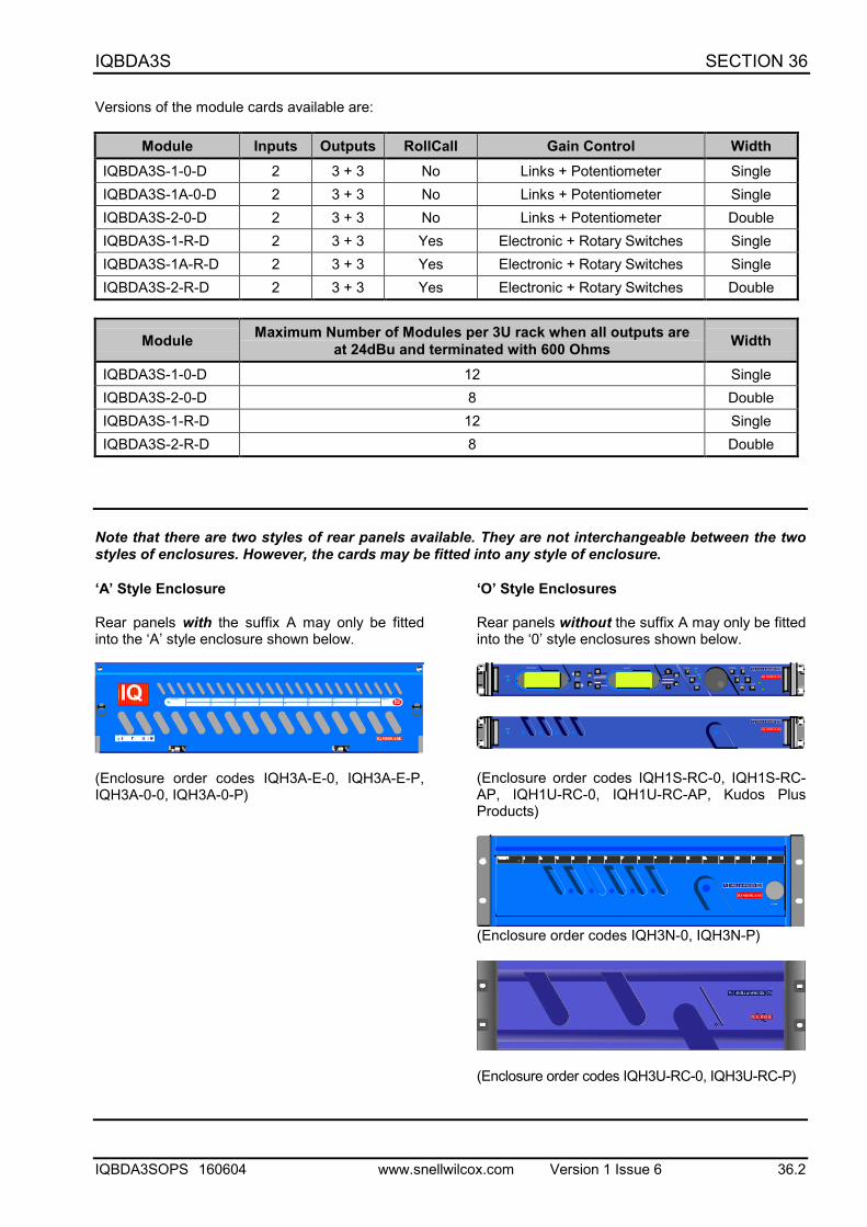
Versions of the module cards available are:
Module Inputs Outputs RollCall Gain Control WidthIQBDA3S-1-0-D 2 3 + 3 No Links + Potentiometer SingleIQBDA3S-1A-0-D 2 3 + 3 No Links + Potentiometer SingleIQBDA3S-2-0-D 2 3 + 3 No Links + Potentiometer DoubleIQBDA3S-1-R-D 2 3 + 3 Yes Electronic + Rotary Switches SingleIQBDA3S-1A-R-D 2 3 + 3 Yes Electronic + Rotary Switches SingleIQBDA3S-2-R-D 2 3 + 3 Yes Electronic + Rotary Switches Double
Module Maximum Number of Modules per 3U rack when all outputs areat 24dBu and terminated with 600 Ohms Width
IQBDA3S-1-0-D 12 SingleIQBDA3S-2-0-D 8 DoubleIQBDA3S-1-R-D 12 SingleIQBDA3S-2-R-D 8 Double
Note that there are two styles of rear panels available. They are not interchangeable between the twostyles of enclosures. However, the cards may be fitted into any style of enclosure.
‘A’ Style Enclosure
Rear panels with the suffix A may only be fittedinto the ‘A’ style enclosure shown below.
IQ
(Enclosure order codes IQH3A-E-0, IQH3A-E-P,IQH3A-0-0, IQH3A-0-P)
‘O’ Style Enclosures
Rear panels without the suffix A may only be fittedinto the ‘0’ style enclosures shown below.
setup
lock save
recall
modules help
adjust
scroll
power previous
return
homecontrolinformation
display select
power
(Enclosure order codes IQH1S-RC-0, IQH1S-RC-AP, IQH1U-RC-0, IQH1U-RC-AP, Kudos PlusProducts)
power
OPEN
(Enclosure order codes IQH3N-0, IQH3N-P)
(Enclosure order codes IQH3U-RC-0, IQH3U-RC-P)
IQBDA3S SECTION 36
IQBDA3SOPS 160604 www.snellwilcox.com Version 1 Issue 6 36.3
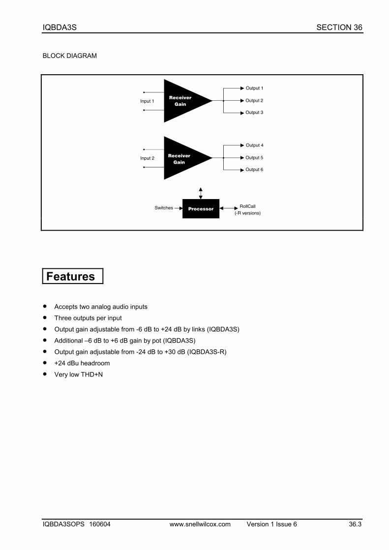
BLOCK DIAGRAM
Input 1
Output 1
ReceiverGain
Output 2
Output 3
Input 2
Output 4
Output 5
Output 6
Switches Processor RollCall
(-R versions)
ReceiverGain
Features
• Accepts two analog audio inputs
• Three outputs per input
• Output gain adjustable from -6 dB to +24 dB by links (IQBDA3S)
• Additional –6 dB to +6 dB gain by pot (IQBDA3S)
• Output gain adjustable from -24 dB to +30 dB (IQBDA3S-R)
• +24 dBu headroom
• Very low THD+N
IQBDA3S SECTION 36
IQBDA3SOPS 160604 www.snellwilcox.com Version 1 Issue 6 36.4
TECHNICAL PROFILE
FeaturesSignal Inputs
Analog ............................... 2 channels balanced via D typeconnector
Signal Outputs
Analog ............................... 3 per channel balanced via D typeconnector
Indicators
Silence L and Right............ <=20 dBu for 40 seconds
Card Edge Controls (also available via RollCall - Rversion only)
Gain (Separate L and R) (-0 version)-6 dB to 24 dB in 6 dB steps(jumper links). -6 dB to +6 dB variable control
Gain (Separate L and R) (-R version)24 dB, -18 dB, -12 dB, -6 dB, 0 dB,+6 dB, +12 dB, +18 dB, +24 dB,+30 dB via card edge rotaryswitches.
Functions Available via RollCall™ Only (- R versiononly)
Gain (Separate L and R) .... -24 dB to +30 dB in 0.5 dB steps
Specifications
Analog Input/Output Level.. Headroom set to:24 dBu (17.5 V pk to pk) Gain atUnity
Analog Input Impedance .... 10 k ohms
Analog Output Impedance . <50 ohms
Total Harmonic Distortion + NoiseLess than 0.005% at 700 Hz,24 dBu in and 0 dB gain
Noise Floor (-0 version)...... Better than –119 dBFS 0 dB gain(20 Hz to 20 kHz)
Noise Floor (-R version) ..... Better than –105 dBFS 0 dB gain(20 Hz to 20 kHz)
Stereo Amplitude Matching (-0 version)Better than ±0.1 dB L to R anygain
Stereo Amplitude Matching (-R version)Better than ±0.2 dB L to R anygain
Gain Accuracy L or R......... Better than ±0.2 dB w.r.t. 0 dB
Common Mode Rejection... Better than -60 dB (20 Hz to20 kHz)
Frequency Flatness ........... Better than +0.1 dBu to -0.3 dBu(20 Hz to 20 kHz with reference to1 kHz)
Headroom (in and out) 24 dBu
Power Consumption
Module Power Consumption8.1 W max (-R versions)7.7 W max (-0 versions)
IQBDA3S SECTION 36
IQBDA3SOPS 160604 www.snellwilcox.com Version 1 Issue 6 36.5
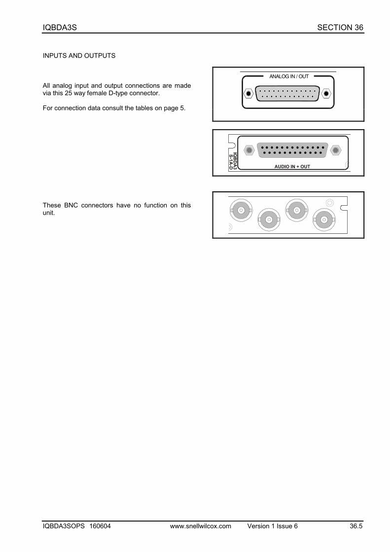
INPUTS AND OUTPUTS
All analog input and output connections are madevia this 25 way female D-type connector.
For connection data consult the tables on page 5.
These BNC connectors have no function on thisunit.
ANALOG IN / OUT
IQBDA3S SECTION 36
IQBDA3SOPS 160604 www.snellwilcox.com Version 1 Issue 6 36.6
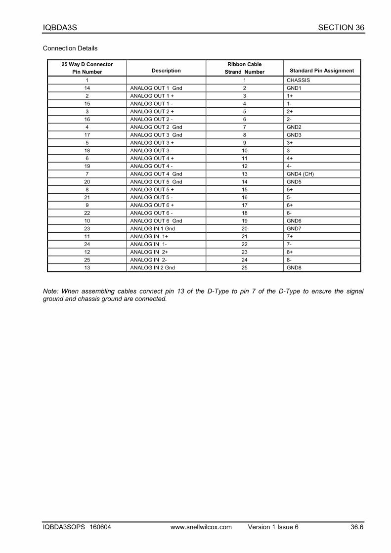
Connection Details
25 Way D ConnectorPin Number Description
Ribbon CableStrand Number Standard Pin Assignment
1 1 CHASSIS14 ANALOG OUT 1 Gnd 2 GND12 ANALOG OUT 1 + 3 1+
15 ANALOG OUT 1 - 4 1-3 ANALOG OUT 2 + 5 2+
16 ANALOG OUT 2 - 6 2-4 ANALOG OUT 2 Gnd 7 GND2
17 ANALOG OUT 3 Gnd 8 GND35 ANALOG OUT 3 + 9 3+
18 ANALOG OUT 3 - 10 3-6 ANALOG OUT 4 + 11 4+
19 ANALOG OUT 4 - 12 4-7 ANALOG OUT 4 Gnd 13 GND4 (CH)
20 ANALOG OUT 5 Gnd 14 GND58 ANALOG OUT 5 + 15 5+
21 ANALOG OUT 5 - 16 5-9 ANALOG OUT 6 + 17 6+
22 ANALOG OUT 6 - 18 6-10 ANALOG OUT 6 Gnd 19 GND623 ANALOG IN 1 Gnd 20 GND711 ANALOG IN 1+ 21 7+24 ANALOG IN 1- 22 7-12 ANALOG IN 2+ 23 8+25 ANALOG IN 2- 24 8-13 ANALOG IN 2 Gnd 25 GND8
Note: When assembling cables connect pin 13 of the D-Type to pin 7 of the D-Type to ensure the signalground and chassis ground are connected.
IQBDA3S SECTION 36
IQBDA3SOPS 160604 www.snellwilcox.com Version 1 Issue 6 36.7
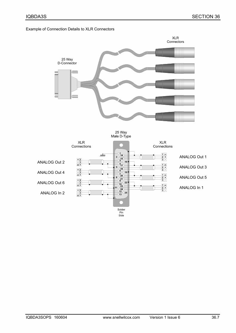
Example of Connection Details to XLR Connectors
ANALOG Out 2
ANALOG Out 4
ANALOG Out 6
ANALOG In 2
ANALOG Out 1
ANALOG Out 3
ANALOG Out 5
ANALOG In 1
IQBDA3S SECTION 36
IQBDA3SOPS 160604 www.snellwilcox.com Version 1 Issue 6 36.8
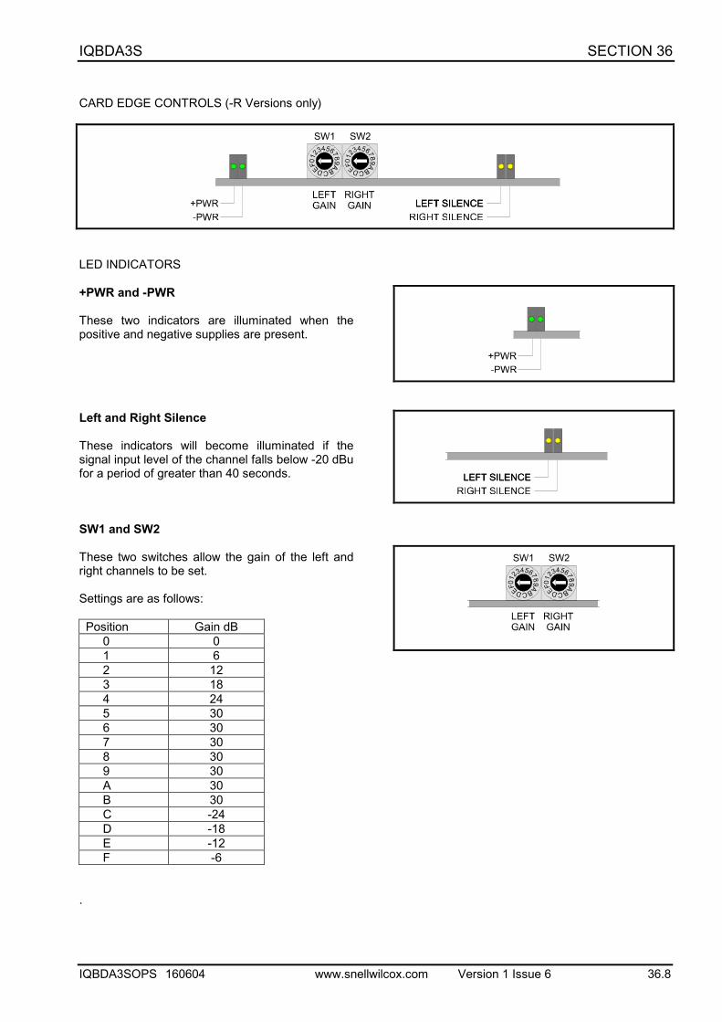
CARD EDGE CONTROLS (-R Versions only)
LED INDICATORS
+PWR and -PWR
These two indicators are illuminated when thepositive and negative supplies are present.
Left and Right Silence
These indicators will become illuminated if thesignal input level of the channel falls below -20 dBufor a period of greater than 40 seconds.
SW1 and SW2
These two switches allow the gain of the left andright channels to be set.
Settings are as follows:
Position Gain dB0 01 62 123 184 245 306 307 308 309 30A 30B 30C -24D -18E -12F -6
.
IQBDA3S SECTION 36
IQBDA3SOPS 160604 www.snellwilcox.com Version 1 Issue 6 36.9
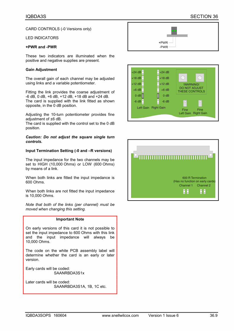
CARD CONTROLS (-0 Versions only)
LED INDICATORS
+PWR and -PWR
These two indicators are illuminated when thepositive and negative supplies are present.
Gain Adjustment
The overall gain of each channel may be adjustedusing links and a variable potentiometer.
Fitting the link provides the coarse adjustment of-6 dB, 0 dB, +6 dB, +12 dB, +18 dB and +24 dB.The card is supplied with the link fitted as shownopposite, in the 0 dB position.
Adjusting the 10-turn potentiometer provides fineadjustment of ±6 dB.The card is supplied with the control set to the 0 dBposition.
Caution: Do not adjust the square single turncontrols.
Input Termination Setting (-0 and –R versions)
The input impedance for the two channels may beset to HIGH (10,000 Ohms) or LOW (600 Ohms)by means of a link.
When both links are fitted the input impedance is600 Ohms.
When both links are not fitted the input impedanceis 10,000 Ohms.
Note that both of the links (per channel) must bemoved when changing this setting.
Important Note
On early versions of this card it is not possible toset the input impedance to 600 Ohms with this linkand the input impedance will always be10,000 Ohms.
The code on the white PCB assembly label willdetermine whether the card is an early or laterversion.
Early cards will be coded:SAANRBDA3S1x
Later cards will be coded:SAANRBDA3S1A, 1B, 1C etc.
FineRight Gain
!WARNING!DO NOT ADJUST
THESE CONTROLS
Right GainFine
Left Gain
Left Gain
+24 dB
+18 dB
+12 dB
+6 dB
0 dB
-6 dB
+24 dB
+18 dB
+12 dB
+6 dB
0 dB
-6 dB
600 R Termination(Has no function on early cards)
Channel 1 Channel 2
IQBDA3S SECTION 36
IQBDA3SOPS 160604 www.snellwilcox.com Version 1 Issue 6 36.10
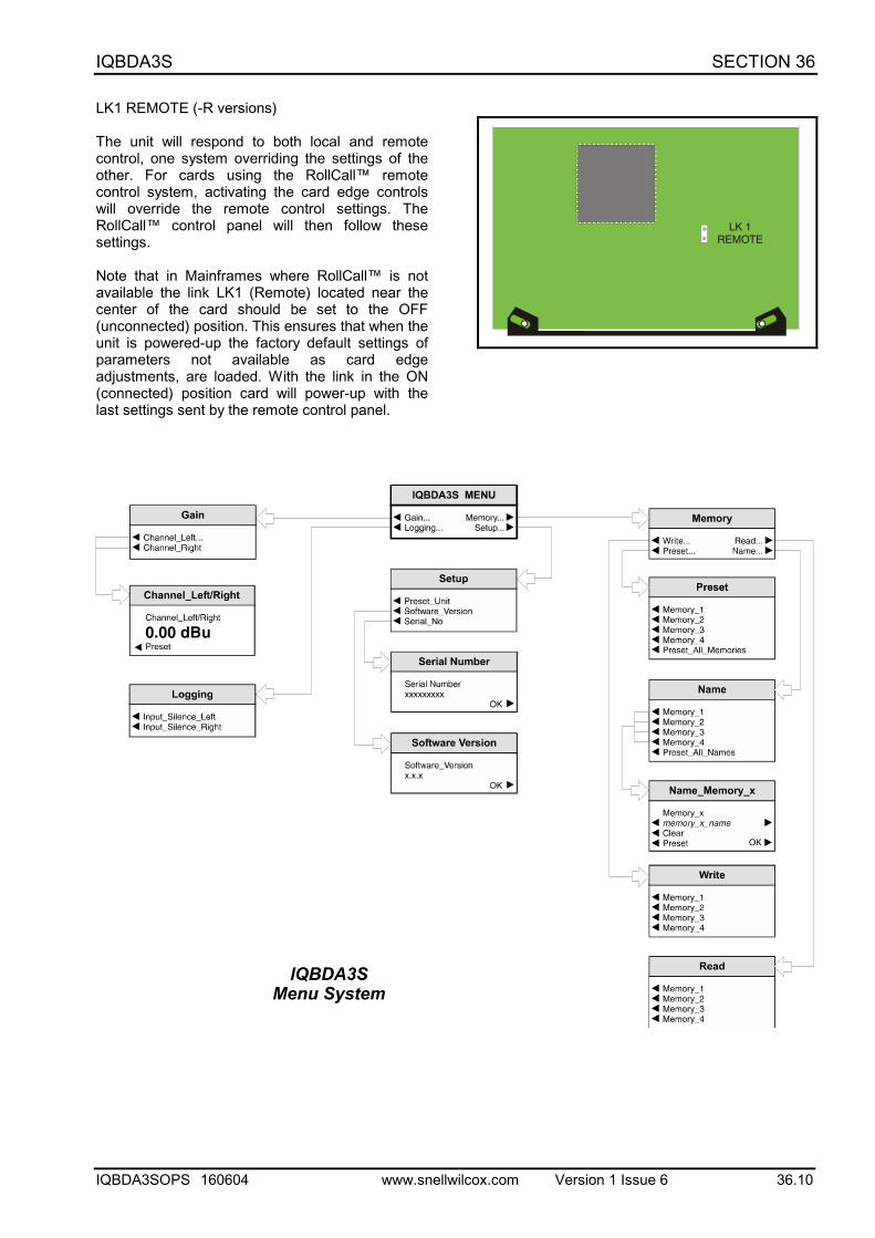
LK1 REMOTE (-R versions)
The unit will respond to both local and remotecontrol, one system overriding the settings of theother. For cards using the RollCall™ remotecontrol system, activating the card edge controlswill override the remote control settings. TheRollCall™ control panel will then follow thesesettings.
Note that in Mainframes where RollCall™ is notavailable the link LK1 (Remote) located near thecenter of the card should be set to the OFF(unconnected) position. This ensures that when theunit is powered-up the factory default settings ofparameters not available as card edgeadjustments, are loaded. With the link in the ON(connected) position card will power-up with thelast settings sent by the remote control panel.
LK 1REMOTE
IQBDA3S SECTION 36
IQBDA3SOPS 160604 www.snellwilcox.com Version 1 Issue 6 36.11
OPERATION FROM AN ACTIVE CONTROL PANEL (-R versions only)
The card may be operated with an active control panel via the RollCall™ network.
The menus available for this card are shown on page opposite and will appear in the Control display window.
Operational details for the remote control panel will be found in SECTION 1 of the Modular System Operator'sManual.
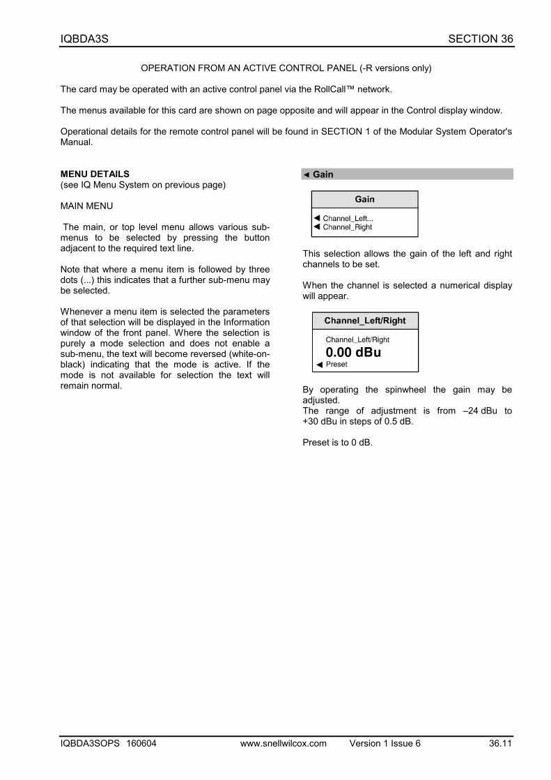
MENU DETAILS(see IQ Menu System on previous page)
MAIN MENU
The main, or top level menu allows various sub-menus to be selected by pressing the buttonadjacent to the required text line.
Note that where a menu item is followed by threedots (...) this indicates that a further sub-menu maybe selected.
Whenever a menu item is selected the parametersof that selection will be displayed in the Informationwindow of the front panel. Where the selection ispurely a mode selection and does not enable asub-menu, the text will become reversed (white-on-black) indicating that the mode is active. If themode is not available for selection the text willremain normal.
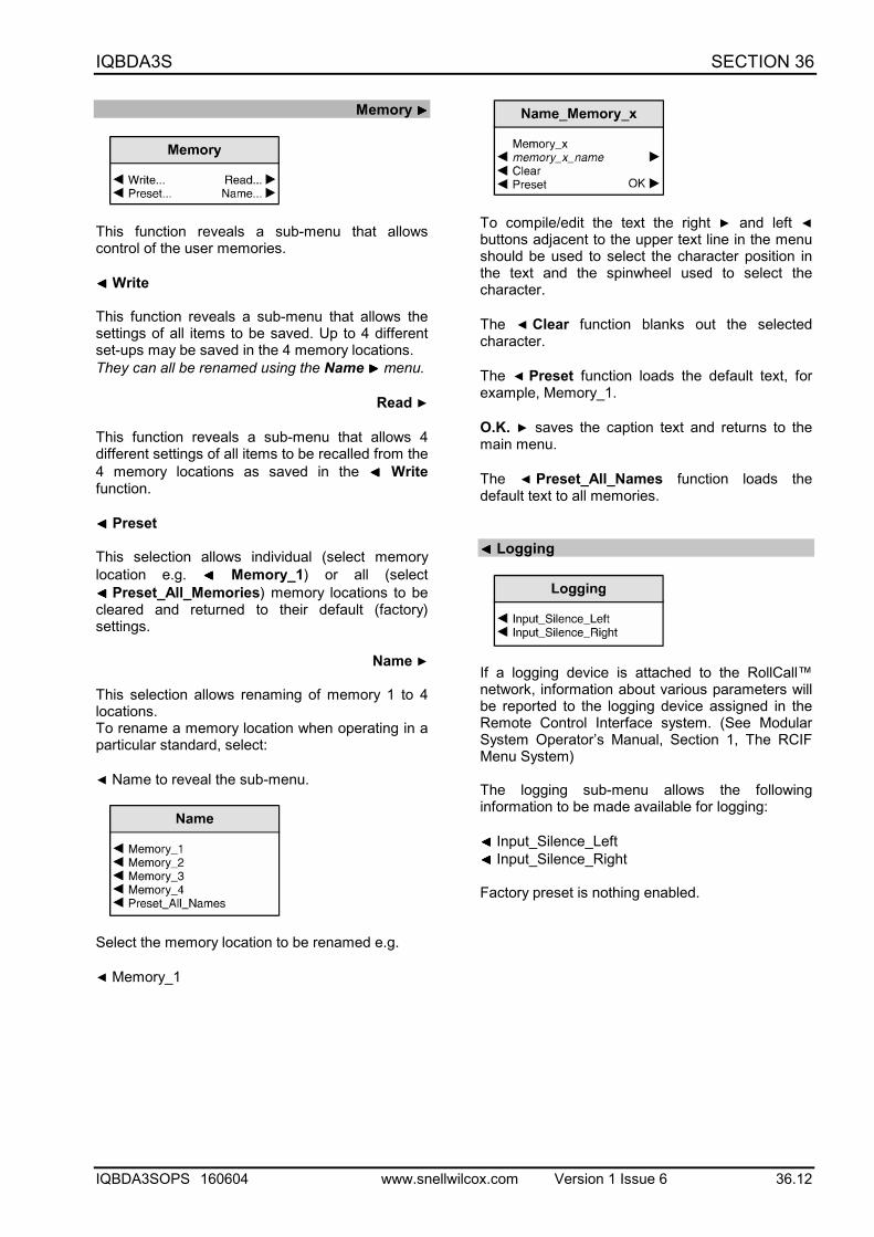
◀ Gain
This selection allows the gain of the left and rightchannels to be set.
When the channel is selected a numerical displaywill appear.
By operating the spinwheel the gain may beadjusted.The range of adjustment is from –24 dBu to+30 dBu in steps of 0.5 dB.
Preset is to 0 dB.
IQBDA3S SECTION 36
IQBDA3SOPS 160604 www.snellwilcox.com Version 1 Issue 6 36.12
Memory ▶▶▶▶
This function reveals a sub-menu that allowscontrol of the user memories.
◀ ◀ ◀ ◀ Write
This function reveals a sub-menu that allows thesettings of all items to be saved. Up to 4 differentset-ups may be saved in the 4 memory locations.They can all be renamed using the Name ▶▶▶▶ menu.
Read ▶
This function reveals a sub-menu that allows 4different settings of all items to be recalled from the4 memory locations as saved in the ◀ ◀ ◀ ◀ Writefunction.
◀ ◀ ◀ ◀ Preset
This selection allows individual (select memorylocation e.g. ◀ ◀ ◀ ◀ Memory_1) or all (select◀◀◀◀ Preset_All_Memories) memory locations to becleared and returned to their default (factory)settings.
Name ▶
This selection allows renaming of memory 1 to 4locations.To rename a memory location when operating in aparticular standard, select:
◀ Name to reveal the sub-menu.
Select the memory location to be renamed e.g.
◀ Memory_1
To compile/edit the text the right ▶ and left ◀buttons adjacent to the upper text line in the menushould be used to select the character position inthe text and the spinwheel used to select thecharacter.
The ◀ Clear function blanks out the selectedcharacter.
The ◀ Preset function loads the default text, forexample, Memory_1.
O.K. ▶ saves the caption text and returns to themain menu.
The ◀ Preset_All_Names function loads thedefault text to all memories.
◀ ◀ ◀ ◀ Logging
If a logging device is attached to the RollCall™network, information about various parameters willbe reported to the logging device assigned in theRemote Control Interface system. (See ModularSystem Operator’s Manual, Section 1, The RCIFMenu System)
The logging sub-menu allows the followinginformation to be made available for logging:
◀ ◀ ◀ ◀ Input_Silence_Left◀ ◀ ◀ ◀ Input_Silence_Right
Factory preset is nothing enabled.
IQBDA3S SECTION 36
IQBDA3SOPS 160604 www.snellwilcox.com Version 1 Issue 6 36.13
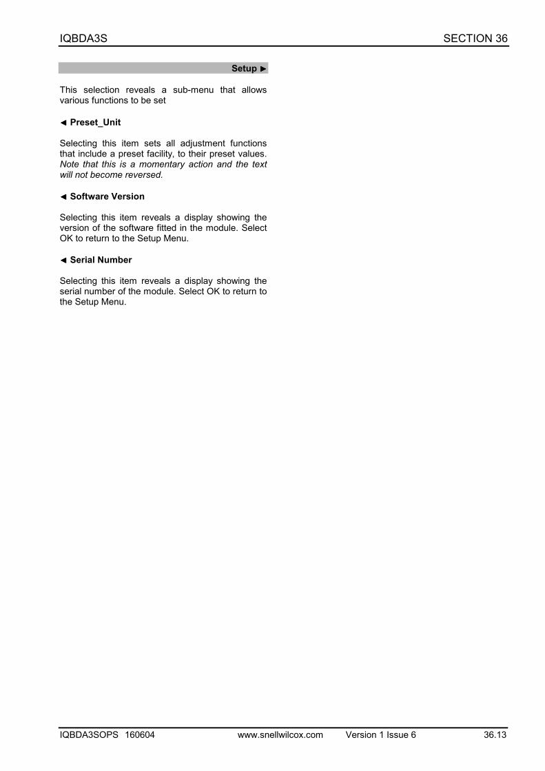
Setup ▶▶▶▶
This selection reveals a sub-menu that allowsvarious functions to be set
◀ ◀ ◀ ◀ Preset_Unit
Selecting this item sets all adjustment functionsthat include a preset facility, to their preset values.Note that this is a momentary action and the textwill not become reversed.
◀ ◀ ◀ ◀ Software Version
Selecting this item reveals a display showing theversion of the software fitted in the module. SelectOK to return to the Setup Menu.
◀ ◀ ◀ ◀ Serial Number
Selecting this item reveals a display showing theserial number of the module. Select OK to return tothe Setup Menu.
IQBDA3S SECTION 36
IQBDA3SOPS 160604 www.snellwilcox.com Version 1 Issue 6 36.14
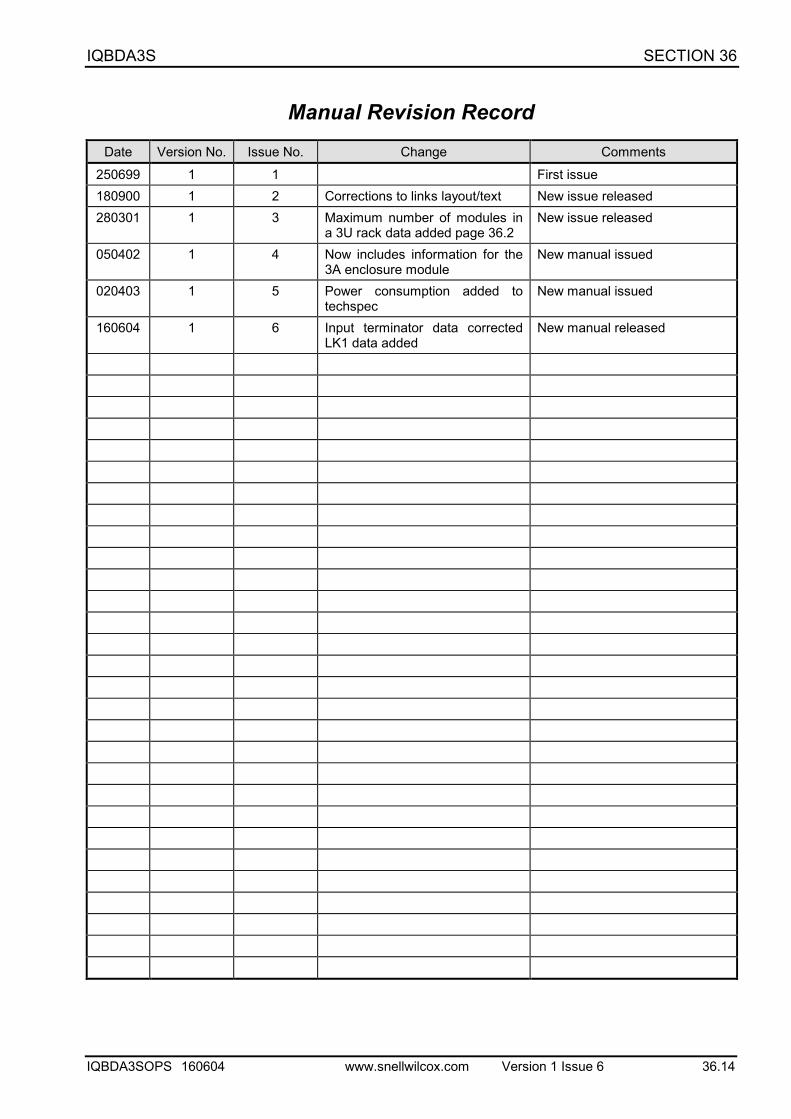
Manual Revision RecordDate Version No. Issue No. Change Comments
250699 1 1 First issue180900 1 2 Corrections to links layout/text New issue released280301 1 3 Maximum number of modules in
a 3U rack data added page 36.2New issue released
050402 1 4 Now includes information for the3A enclosure module
New manual issued
020403 1 5 Power consumption added totechspec
New manual issued
160604 1 6 Input terminator data correctedLK1 data added
New manual released