Embed Size (px)
Citation preview
Analog Input Modules
P2-04AD $210.00Voltage/Current Analog InputThe P2-04AD Voltage/Current Analog Input Module provides four channels for receiving ±10VDC, ±5VDC, 0–5 VDC and 0 to 20 mA signals.
1–9.453V2 18.233 UNDER4 SPARE
Terminal block sold separately.
Input SpecificationsInput Channels 4
Module Signal Input Ranges ±10VDC, ±5VDC, 0–5 VDC, 0–10 VDC, 0–20mA
Signal Resolution 16-bit
Resolution Value of LSB (least significant bit)
1 LSB = 1 count ±10V = 305μV ±5V = 152μV
0–5V = 76μV 0–10V = 152μV 0–20mA = 0.305 μA
Data Range0-65535 counts unipolar -32768 to +32767 counts bipolar
Maximum Continuous Overload±31mA, current input ±100V, voltage input
Input Impedance1MΩ ±10% voltage input 250Ω ±0.1% 1/4 W current input
Hardware Filter Characteristics Low Pass 1st order, -3dB @ 48Hz
Sample Duration Time 2ms per channel (does not include ladder scan time)
All Channel Update Rate 8ms
Open Circuit Detection Time Zero reading within 1s (current input only)
Conversion Method Successive approximation
Accuracy vs. Temperature ±10PPM / ºC maximum
Maximum Inaccuracy0.1% of range voltage, 0.2% of range current (including temperature drift)
Linearity Error (end to end)±0.01% of range max., ±10V & ±5V ±0.015% of range max., 0–10V, 0–5V & 0–20mA Monotonic with no missing codes
Input Stability and Repeatability ±0.035% of range (after 10 min. warmup)
Full Scale Calibration Error ±0.2% of range maximum
Offset Calibration Error ±0.065% of range maximum
Max Crosstalk -96dB, 1 LSB
Recommended Fuse (external)Edison S500-32-R, 0.032A fuse on current inputs only
External DC Power Required 24VDC (-20% / +25%) 35mA
General SpecificationsOperating Temperature 0º to 60ºC (32º to 140ºF)
Storage Temperature -20º to 70ºC (-4º to 158ºF)
Humidity 5 to 95% (non-condensing)
Environmental Air No corrosive gases permitted
Vibration IEC60068-2-6 (Test Fc)
Shock IEC60068-2-27 (Test Ea)
Field to Logic Side Isolation 1800VAC applied for 1 second
Insulation Resistance >10MΩ @ 500VDCHeat Dissipation 1.4 WEnclosure Type Open EquipmentModule Keying to Backplane Electronic
Module Location Any I/O slot in a Productivity2000 System
Field WiringUse ZIPLink Wiring System or removable terminal block (not included). See Wiring Solutions.
EU Directive
See the “EU Directive” topic in the Productivity Suite Help File. Information can also be obtained at: www.productivity2000.com
Connector Type (Sold separately) 18-position removable terminal block
Weight 90g (3.2 oz)
Agency Approvals**
UL 61010-1 and UL 61010-2-201 File E139594, Canada & USACE (EN 61131-2 EMC, EN 61010-1 and EN 61010-2-201 Safety)*
We recommend using prewired ZIPLink cables and connection modules. See Wiring Solutions.
If you wish to hand-wire your module, a remov-able terminal block is sold separately. Order part number P2-RTB or P2-RTB-1.
ULC USR
*Meets EMC and Safety requirements. See the Declaration of Conformity for details.**To obtain the most current agency approval information, see the Agency Approval Checklist section on the specific component part number web page.
w w w . a u t o m a t i o n d i r e c t . c o m / p r o d u c t i v i t y 2 0 0 0 Productivity®2000 Controllers PR2-83
For the latest prices, please check AutomationDirect.com.
V1+I1+V2+I2+V3+I3+
I4+V4+
COMCOM
24VDC-24VDC+- +
24 VDC UserSupplied Power
CH1 ADC
CH2 ADC
CH3 ADC
CH4 ADC
ISOLATEDANALOGCIRCUITPOWER
ISOLATED ANALOGCIRCUIT COMMON
INTERNALMODULE CIRCUITRY
COM
COM 12
34
56
78
910
1112
1813
1415
1617
Analog Input Modules
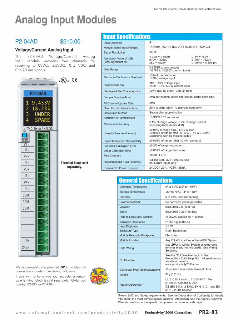
P2-04AD (cont’d)Wiring Diagrams
Voltage Input Circuits
Current Sinking Input CircuitsAn Edison S500-32-R 0.032A fast-acting fuse is recommended for all current loops.
COM
V+
4-Wire VoltageTransmitter
4-Wire Transmitter
Optional TransmitterPower SupplyAC or DC
- +
24 VDC User Supplied Power
+3-Wire VoltageTransmitter
V+
COM
3-Wire Transmitter
.032A2-Wire 4-20 mATransmitter
fuse
fuse
.032Afuse
+
.032A
- +
- +
V+
I+
COM
V+
I+
3-Wire CurrentTransmitter
4-Wire 4-20 mATransmitter
2-Wire Transmitter
3-Wire Transmitter
4-Wire Transmitter
PowerSupply
24VDC User Supplied Power
+
–
+
–
+
–
User SuppliedTransmitter Power AC or DC
V+
I+
COM
COM
Removable Terminal Block SpecificationsPart Number P2-RTB P2-RTB-1
Number of positions 18 Screw Terminals 18 Spring Clamp Terminals
Wire Range30–16 AWG (0.051–1.31 mm²)Solid / Stranded Conductor3/64 in (1.2 mm) Insulation Maximum1/4 in (6–7 mm) Strip Length
28–16 AWG (0.081–1.31 mm²)Solid / Stranded Conductor3/64 in (1.2 mm) Insulation Maximum19/64 in (7–8 mm) Strip Length
Conductors “USE COPPER CONDUCTORS, 75ºC” or equivalent.
Screw Driver Width 1/8 in (3.8 mm) Maximum
Screw Size M2 N/A
Screw Torque 2.5 lb·in (0.28 N·m) N/A
Notes: 1. Shield connected to signal source common.2. If current is chosen, I+ MUST be jumpered to V+. For example,
when using 4–20 mA source for Input 3, I3+ must be connected to V3+.
1 - 8 0 0 - 6 3 3 - 0 4 0 5PR2-84 Productivity®2000 Controllers
For the latest prices, please check AutomationDirect.com.
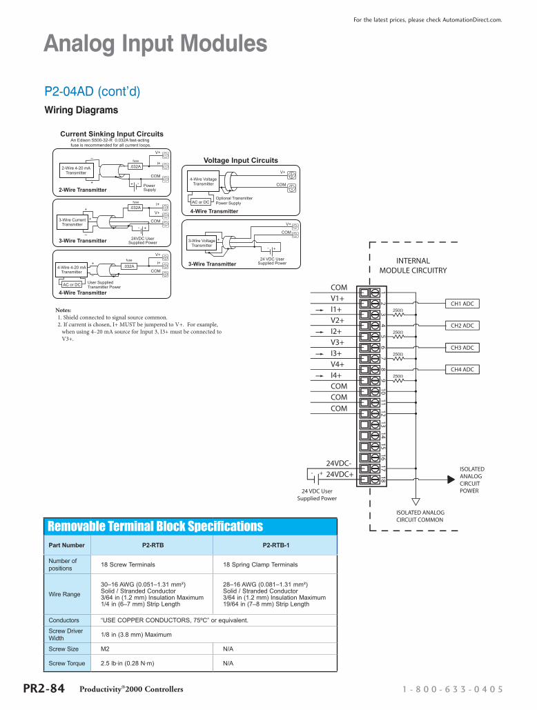
Wiring I/O Modules
ZIPLink Module
ZIPLink Pre-Wired Terminal Block Cable
ZIPLink Pigtail Cable
Terminal Block Removal
There are two available methods for wiring most I/O modules: The ZIPLink wiring system or hand wiring to the optional removable I/O module terminal blocks.
Note: Thermocouple and RTD modules are not compatible with the ZIPLink system and are shipped with the optional terminal blocks included.
ZIPLinks Wiring SystemsFor wiring I/O modules, we strongly recommend using pre-wired ZIPLinks wiring systems, which eliminate the need for hand wiring modules to terminal blocks.
See the selection matrix guide on the following pages.
Removable Terminal Block P2-RTB
Removable Terminal Block P2-RTB-1
WIRE STRIPLENGTHWIRE STRIPLENGTH
Removable Terminal BlocksFor most I/O modules you can also purchase a removable terminal block (part no. P2-RTB or P2-RTB-1).
Note: P2-RTB supplied with Thermocouple and RTD modules.
Removable Terminal Block Specifications
Part Number P2-RTB P2-RTB-1Number of Positions 18 Screw Terminals 18 Spring Clamp Terminals
Wire Range
30–16 AWG (0.051–1.31 mm2) Solid / Stranded Conductor 3/64 in (1.2 mm) Insulation Maximum1/4 in (6–7 mm) Strip Length
28–16 AWG (0.081–1.31 mm2) Solid / Stranded Conductor 3/64 in (1.2 mm) Insulation Maximum19/64 in (7–8 mm) Strip Length
Conductors USE COPPER CONDUCTORS, 75°C” or Equivalent.
Screw Driver Width 1/8 inch (3.8 mm) Maximum
Screw Size M2 N/A
Screw Torque 2.5 lb·in (0.28 N·m) N/A
w w w . a u t o m a t i o n d i r e c t . c o m / p r o d u c t i v i t y 2 0 0 0 Productivity®2000 Controllers PR2-31
For the latest prices, please check AutomationDirect.com.
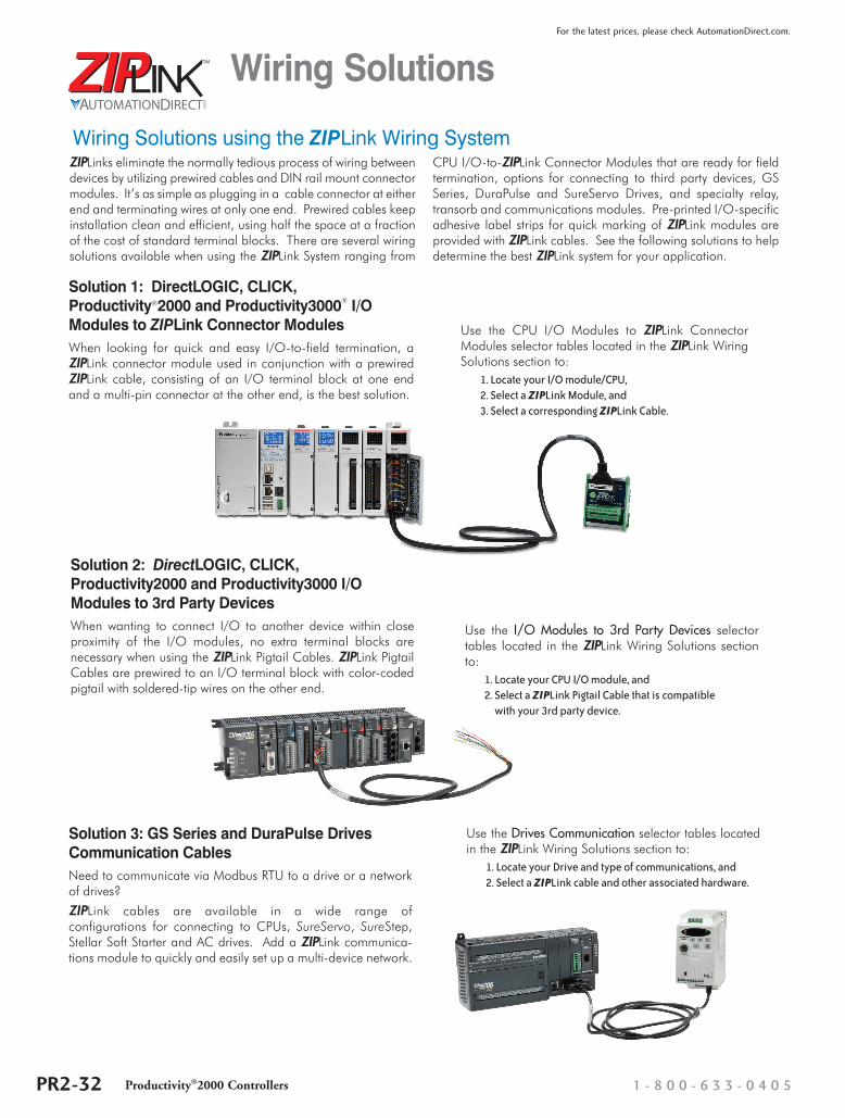
Wiring Solutions
ZIPLinks eliminate the normally tedious process of wiring between devices by utilizing prewired cables and DIN rail mount connector modules. It’s as simple as plugging in a cable connector at either end and terminating wires at only one end. Prewired cables keep installation clean and efficient, using half the space at a fraction of the cost of standard terminal blocks. There are several wiring solutions available when using the ZIPLink System ranging from
CPU I/O-to-ZIPLink Connector Modules that are ready for field termination, options for connecting to third party devices, GS Series, DuraPulse and SureServo Drives, and specialty relay, transorb and communications modules. Pre-printed I/O-specific adhesive label strips for quick marking of ZIPLink modules are provided with ZIPLink cables. See the following solutions to help determine the best ZIPLink system for your application.
Solution 1: DirectLOGIC, CLICK, Productivity®2000 and Productivity3000® I/O Modules to ZIPLink Connector ModulesWhen looking for quick and easy I/O-to-field termination, a ZIPLink connector module used in conjunction with a prewired ZIPLink cable, consisting of an I/O terminal block at one end and a multi-pin connector at the other end, is the best solution.
Use the CPU I/O Modules to ZIPLink Connector Modules selector tables located in the ZIPLink Wiring Solutions section to:
1. Locate your I/O module/CPU, 2. Select a ZIPLink Module, and 3. Select a corresponding ZIPLink Cable.
Use the Drives Communication selector tables located in the ZIPLink Wiring Solutions section to:
1. Locate your Drive and type of communications, and 2. Select a ZIPLink cable and other associated hardware.
Solution 2: DirectLOGIC, CLICK, Productivity2000 and Productivity3000 I/O Modules to 3rd Party DevicesWhen wanting to connect I/O to another device within close proximity of the I/O modules, no extra terminal blocks are necessary when using the ZIPLink Pigtail Cables. ZIPLink Pigtail Cables are prewired to an I/O terminal block with color-coded pigtail with soldered-tip wires on the other end.
Wiring Solutions using the ZIPLink Wiring System
Use the I/O Modules to 3rd Party Devices selector tables located in the ZIPLink Wiring Solutions section to:
1. Locate your CPU I/O module, and 2. Select a ZIPLink Pigtail Cable that is compatible
with your 3rd party device.
Solution 3: GS Series and DuraPulse Drives Communication CablesNeed to communicate via Modbus RTU to a drive or a network of drives?
ZIPLink cables are available in a wide range of configurations for connecting to CPUs, SureServo, SureStep, Stellar Soft Starter and AC drives. Add a ZIPLink communica-tions module to quickly and easily set up a multi-device network.
1 - 8 0 0 - 6 3 3 - 0 4 0 5PR2-32 Productivity®2000 Controllers
For the latest prices, please check AutomationDirect.com.
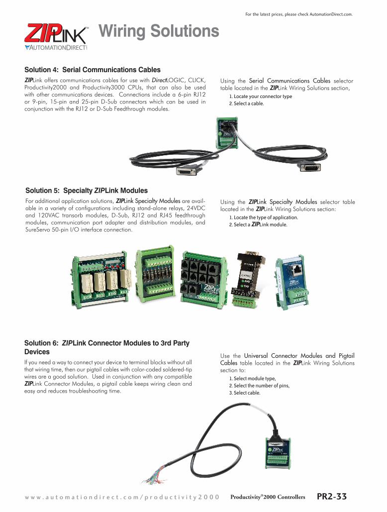
Wiring Solutions
Solution 4: Serial Communications CablesZIPLink offers communications cables for use with DirectLOGIC, CLICK, Productivity2000 and Productivity3000 CPUs, that can also be used with other communications devices. Connections include a 6-pin RJ12 or 9-pin, 15-pin and 25-pin D-Sub connectors which can be used in conjunction with the RJ12 or D-Sub Feedthrough modules.
Using the Serial Communications Cables selector table located in the ZIPLink Wiring Solutions section,
1. Locate your connector type 2. Select a cable.
Solution 5: Specialty ZIPLink ModulesFor additional application solutions, ZIPLink Specialty Modules are avail-able in a variety of configurations including stand-alone relays, 24VDC and 120VAC transorb modules, D-Sub, RJ12 and RJ45 feedthrough modules, communication port adapter and distribution modules, and SureServo 50-pin I/O interface connection.
Using the ZIPLink Specialty Modules selector table located in the ZIPLink Wiring Solutions section:
1. Locate the type of application. 2. Select a ZIPLink module.
Solution 6: ZIPLink Connector Modules to 3rd Party DevicesIf you need a way to connect your device to terminal blocks without all that wiring time, then our pigtail cables with color-coded soldered-tip wires are a good solution. Used in conjunction with any compatible ZIPLink Connector Modules, a pigtail cable keeps wiring clean and easy and reduces troubleshooting time.
Use the Universal Connector Modules and Pigtail Cables table located in the ZIPLink Wiring Solutions section to:
1. Select module type, 2. Select the number of pins, 3. Select cable.
w w w . a u t o m a t i o n d i r e c t . c o m / p r o d u c t i v i t y 2 0 0 0 Productivity®2000 Controllers PR2-33
For the latest prices, please check AutomationDirect.com.
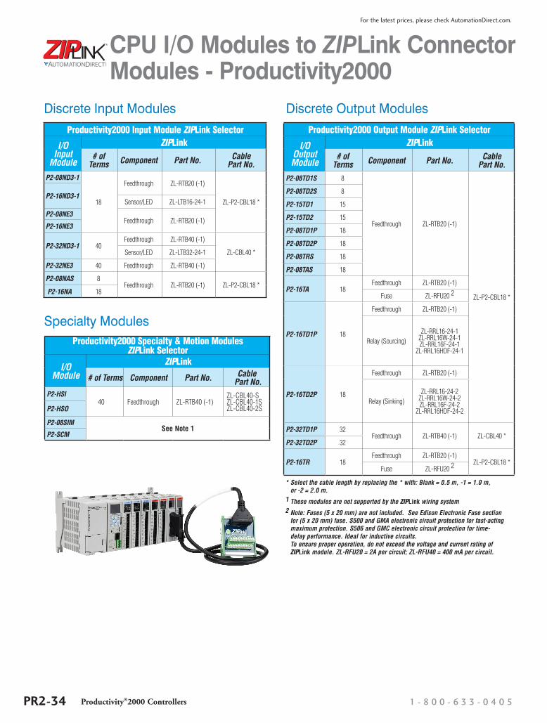
CPU I/O Modules to ZIPLink Connector Modules - Productivity2000
Productivity2000 Output Module ZIPLink Selector
I/O Output Module
ZIPLink# of
Terms Component Part No. Cable Part No.
P2-08TD1S 8
Feedthrough ZL-RTB20 (-1)
ZL-P2-CBL18 *
P2-08TD2S 8
P2-15TD1 15
P2-15TD2 15
P2-08TD1P 18
P2-08TD2P 18
P2-08TRS 18
P2-08TAS 18
P2-16TA 18Feedthrough ZL-RTB20 (-1)
Fuse ZL-RFU20 2
P2-16TD1P 18
Feedthrough ZL-RTB20 (-1)
Relay (Sourcing)ZL-RRL16-24-1
ZL-RRL16W-24-1 ZL-RRL16F-24-1
ZL-RRL16HDF-24-1
P2-16TD2P 18
Feedthrough ZL-RTB20 (-1)
Relay (Sinking)ZL-RRL16-24-2
ZL-RRL16W-24-2 ZL-RRL16F-24-2
ZL-RRL16HDF-24-2
P2-32TD1P 32Feedthrough ZL-RTB40 (-1) ZL-CBL40 *
P2-32TD2P 32
P2-16TR 18Feedthrough ZL-RTB20 (-1)
ZL-P2-CBL18 *Fuse ZL-RFU20 2
* Select the cable length by replacing the * with: Blank = 0.5 m, -1 = 1.0 m, or -2 = 2.0 m.
1 These modules are not supported by the ZIPLink wiring system2 Note: Fuses (5 x 20 mm) are not included. See Edison Electronic Fuse section
for (5 x 20 mm) fuse. S500 and GMA electronic circuit protection for fast-acting maximum protection. S506 and GMC electronic circuit protection for time-delay performance. Ideal for inductive circuits. To ensure proper operation, do not exceed the voltage and current rating of ZIPLink module. ZL-RFU20 = 2A per circuit; ZL-RFU40 = 400 mA per circuit.
Productivity2000 Specialty & Motion Modules ZIPLink Selector
I/O Module
ZIPLink
# of Terms Component Part No. Cable Part No.
P2-HSI40 Feedthrough ZL-RTB40 (-1)
ZL-CBL40-S ZL-CBL40-1S ZL-CBL40-2SP2-HSO
P2-08SIMSee Note 1
P2-SCM
Productivity2000 Input Module ZIPLink Selector
I/O Input
Module
ZIPLink# of
Terms Component Part No. Cable Part No.
P2-08ND3-1
18
Feedthrough ZL-RTB20 (-1)
ZL-P2-CBL18 *P2-16ND3-1
Sensor/LED ZL-LTB16-24-1
P2-08NE3Feedthrough ZL-RTB20 (-1)
P2-16NE3
P2-32ND3-1 40Feedthrough ZL-RTB40 (-1)
ZL-CBL40 *Sensor/LED ZL-LTB32-24-1
P2-32NE3 40 Feedthrough ZL-RTB40 (-1)
P2-08NAS 8Feedthrough ZL-RTB20 (-1) ZL-P2-CBL18 *
P2-16NA 18
Discrete Input Modules Discrete Output Modules
Specialty Modules
1 - 8 0 0 - 6 3 3 - 0 4 0 5PR2-34 Productivity®2000 Controllers
For the latest prices, please check AutomationDirect.com.
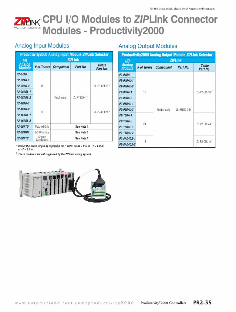
CPU I/O Modules to ZIPLink Connector Modules - Productivity2000
Productivity2000 Analog Input Module ZIPLink SelectorI/O
Analog Module
ZIPLink
# of Terms Component Part No. Cable Part No.
P2-04AD
18
Feedthrough ZL-RTB20 (-1)
ZL-P2-CBL18 *
P2-08AD-1
P2-08AD-2
P2-08ADL-1
P2-08ADL-2
P2-16AD-1
24 ZL-P2-CBL24 *P2-16AD-2
P2-16ADL-1
P2-16ADL-2
P2-06RTD Matched Only See Note 1
P2-08THM T/C Wire Only See Note 1
P2-08NTC Copper Conductors See Note 1
Productivity2000 Analog Output Module ZIPLink SelectorI/O
Analog Module
ZIPLink
# of Terms Component Part No. Cable Part No.
P2-04DA
18
Feedthrough ZL-RTB20 (-1)
ZL-P2-CBL18 *
P2-04DAL-1
P2-04DAL-2
P2-08DA-1
P2-08DA-2
P2-08DAL-1
P2-08DAL-2
P2-16DA-1
24 ZL-P2-CBL24 *P2-16DA-2
P2-16DAL-1
P2-16DAL-2
P2-8AD4DA-118 ZL-P2-CBL18 *
P2-8AD4DA-2* Select the cable length by replacing the * with: Blank = 0.5 m, -1 = 1.0 m, or -2 = 2.0 m.
1 These modules are not supported by the ZIPLink wiring system.
Analog Input Modules Analog Output Modules
w w w . a u t o m a t i o n d i r e c t . c o m / p r o d u c t i v i t y 2 0 0 0 Productivity®2000 Controllers PR2-35
For the latest prices, please check AutomationDirect.com.
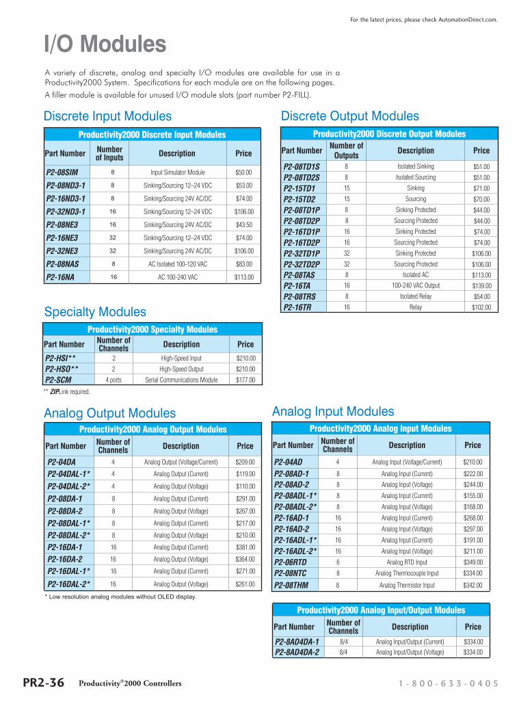
I/O ModulesA variety of discrete, analog and specialty I/O modules are available for use in a Productivity2000 System. Specifications for each module are on the following pages.
A filler module is available for unused I/O module slots (part number P2-FILL).
Productivity2000 Discrete Output Modules
Part Number Number of Outputs Description Price
P2-08TD1S 8 Isolated Sinking $51.00
P2-08TD2S 8 Isolated Sourcing $51.00
P2-15TD1 15 Sinking $71.00
P2-15TD2 15 Sourcing $70.00
P2-08TD1P 8 Sinking Protected $44.00
P2-08TD2P 8 Sourcing Protected $44.00
P2-16TD1P 16 Sinking Protected $74.00
P2-16TD2P 16 Sourcing Protected $74.00
P2-32TD1P 32 Sinking Protected $106.00
P2-32TD2P 32 Sourcing Protected $106.00
P2-08TAS 8 Isolated AC $113.00
P2-16TA 16 100-240 VAC Output $139.00
P2-08TRS 8 Isolated Relay $54.00
P2-16TR 16 Relay $102.00
Discrete Input Modules Discrete Output ModulesProductivity2000 Discrete Input Modules
Part Number Number of Inputs Description Price
P2-08SIM 8 Input Simulator Module $50.00
P2-08ND3-1 8 Sinking/Sourcing 12–24 VDC $53.00
P2-16ND3-1 8 Sinking/Sourcing 24V AC/DC $74.00
P2-32ND3-1 16 Sinking/Sourcing 12–24 VDC $106.00
P2-08NE3 16 Sinking/Sourcing 24V AC/DC $43.50
P2-16NE3 32 Sinking/Sourcing 12–24 VDC $74.00
P2-32NE3 32 Sinking/Sourcing 24V AC/DC $106.00
P2-08NAS 8 AC Isolated 100-120 VAC $83.00
P2-16NA 16 AC 100-240 VAC $113.00
Productivity2000 Analog Output Modules
Part Number Number of Channels Description Price
P2-04DA 4 Analog Output (Voltage/Current) $209.00
P2-04DAL-1* 4 Analog Output (Current) $119.00
P2-04DAL-2* 4 Analog Output (Voltage) $110.00
P2-08DA-1 8 Analog Output (Current) $291.00
P2-08DA-2 8 Analog Output (Voltage) $267.00
P2-08DAL-1* 8 Analog Output (Current) $217.00
P2-08DAL-2* 8 Analog Output (Voltage) $210.00
P2-16DA-1 16 Analog Output (Current) $381.00
P2-16DA-2 16 Analog Output (Voltage) $364.00
P2-16DAL-1* 16 Analog Output (Current) $271.00
P2-16DAL-2* 16 Analog Output (Voltage) $261.00
Productivity2000 Analog Input/Output Modules
Part Number Number of Channels Description Price
P2-8AD4DA-1 8/4 Analog Input/Output (Current) $334.00
P2-8AD4DA-2 8/4 Analog Input/Output (Voltage) $334.00
Specialty Modules
Analog Input Modules
Productivity2000 Specialty Modules
Part Number Number of Channels Description Price
P2-HSI** 2 High-Speed Input $210.00
P2-HSO** 2 High-Speed Output $210.00
P2-SCM 4 ports Serial Communications Module $177.00
** ZIPLink required.
Productivity2000 Analog Input Modules
Part Number Number of Channels Description Price
P2-04AD 4 Analog Input (Voltage/Current) $210.00
P2-08AD-1 8 Analog Input (Current) $222.00
P2-08AD-2 8 Analog Input (Voltage) $244.00
P2-08ADL-1* 8 Analog Input (Current) $155.00
P2-08ADL-2* 8 Analog Input (Voltage) $168.00
P2-16AD-1 16 Analog Input (Current) $268.00
P2-16AD-2 16 Analog Input (Voltage) $297.00
P2-16ADL-1* 16 Analog Input (Current) $191.00
P2-16ADL-2* 16 Analog Input (Voltage) $211.00
P2-06RTD 6 Analog RTD Input $349.00
P2-08NTC 8 Analog Thermocouple Input $334.00
P2-08THM 8 Analog Thermistor Input $342.00
Analog Output Modules
* Low resolution analog modules without OLED display.
1 - 8 0 0 - 6 3 3 - 0 4 0 5PR2-36 Productivity®2000 Controllers
For the latest prices, please check AutomationDirect.com.
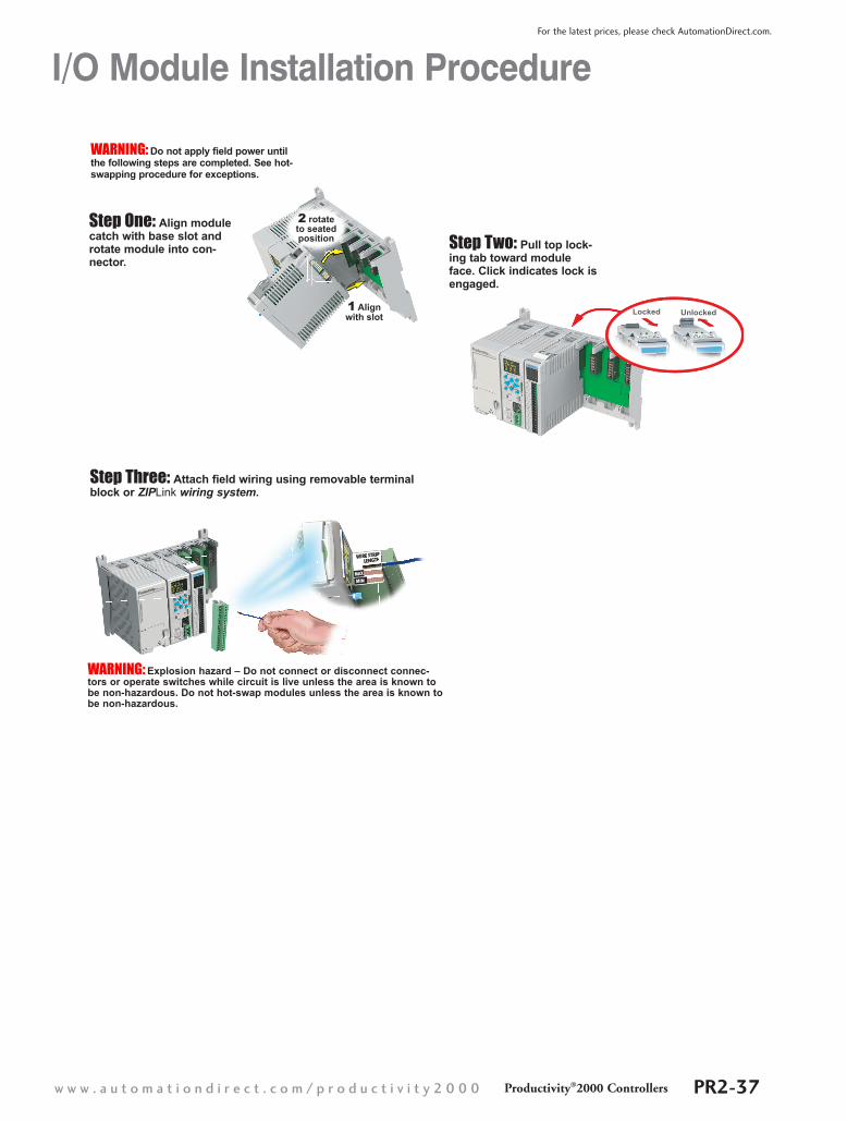
Step Three: Attach field wiring using removable terminal block or ZIPLink wiring system.
Step One: Align module catch with base slot and rotate module into con-nector.
WARNING: Explosion hazard – Do not connect or disconnect connec-tors or operate switches while circuit is live unless the area is known to be non-hazardous. Do not hot-swap modules unless the area is known to be non-hazardous.
Locked Unlocked1 Alignwith slot
2 rotateto seatedposition
WIRE STRIPLENGTHWIRE STRIPLENGTH
Step Two: Pull top lock-ing tab toward module face. Click indicates lock is engaged.
WARNING: Do not apply field power until the following steps are completed. See hot-swapping procedure for exceptions.
I/O Module Installation Procedure
w w w . a u t o m a t i o n d i r e c t . c o m / p r o d u c t i v i t y 2 0 0 0 Productivity®2000 Controllers PR2-37
For the latest prices, please check AutomationDirect.com.