Embed Size (px)
Citation preview
IQ422/.. Controller Data Sheet TA201260 Issue 6, 14-Oct-2015. Applies to v3.30. 1
Data Sheet
IQ422/..Controller
IQ422
Description
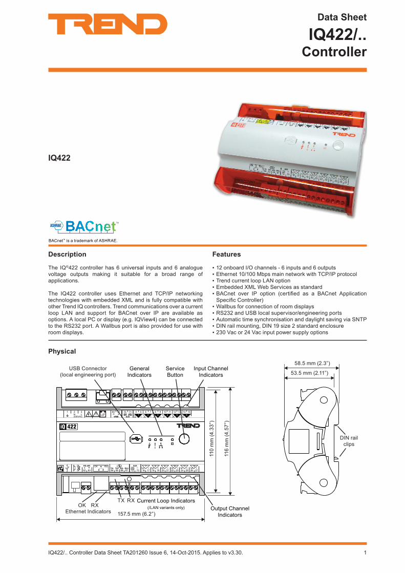
The IQ®422 controller has 6 universal inputs and 6 analogue voltage outputs making it suitable for a broad range of applications.
The IQ422 controller uses Ethernet and TCP/IP networking technologies with embedded XML and is fully compatible with other Trend IQ controllers. Trend communications over a current loop LAN and support for BACnet over IP are available as options. A local PC or display (e.g. IQView4) can be connected to the RS232 port. A Wallbus port is also provided for use with room displays.
Physical
110
mm
(4.3
3”)
116
mm
(4.5
7”)
58.5 mm (2.3”)
53.5 mm (2.11”)
157.5 mm (6.2”)
USB Connector(local engineering port)
General Indicators
Input Channel Indicators
Service Button
RXOKEthernet Indicators
TX RXOutput Channel
Indicators
Current Loop Indicators (/LAN variants only)
DIN rail clips
Features
12 onboard I/O channels - 6 inputs and 6 outputs Ethernet 10/100 Mbps main network with TCP/IP protocol Trend current loop LAN option Embedded XML Web Services as standard BACnet over IP option (certified as a BACnet Application Specific Controller)
Wallbus for connection of room displays RS232 and USB local supervisor/engineering ports Automatic time synchronisation and daylight saving via SNTP DIN rail mounting, DIN 19 size 2 standard enclosure 230 Vac or 24 Vac input power supply options
BACnet™ is a trademark of ASHRAE.
2 IQ422/.. Controller Data Sheet TA201260 Issue 6, 14-Oct-2015. Applies to v3.30.
IQ422/.. Data Sheet
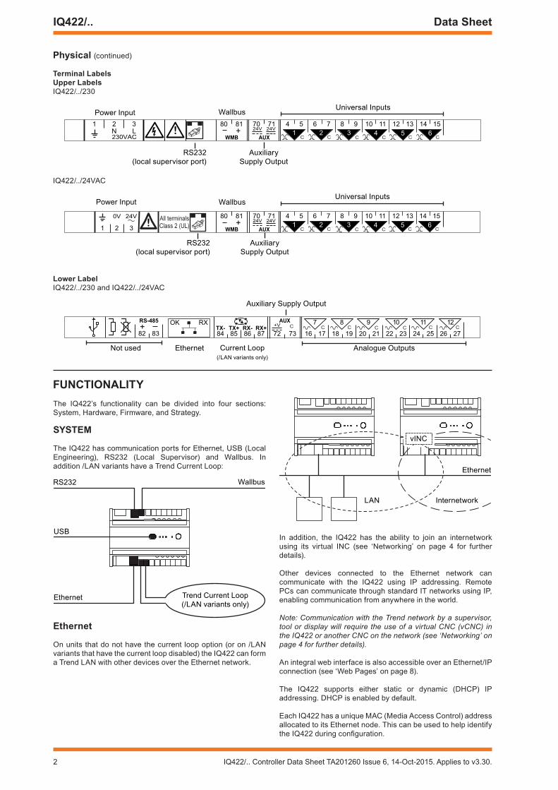
Physical (continued)
Terminal LabelsUpper Labels IQ422/../230
Universal Inputs
Auxiliary Supply Output
RS232 (local supervisor port)
Power Input Wallbus
IQ422/../24VAC
Universal Inputs
Auxiliary Supply Output
RS232 (local supervisor port)
Power Input Wallbus
Lower LabelIQ422/../230 and IQ422/../24VAC
Current Loop (/LAN variants only)
Auxiliary Supply Output
Analogue OutputsEthernetNot used
FUnCTIonaLITyThe IQ422’s functionality can be divided into four sections: System, Hardware, Firmware, and Strategy.
SySTem
The IQ422 has communication ports for Ethernet, USB (Local Engineering), RS232 (Local Supervisor) and Wallbus. In addition /LAN variants have a Trend Current Loop:
RS232 Wallbus
USB
Ethernet Trend Current Loop (/LAN variants only)
ethernet
On units that do not have the current loop option (or on /LAN variants that have the current loop disabled) the IQ422 can form a Trend LAN with other devices over the Ethernet network.
LAN Internetwork
Ethernet
vINC
In addition, the IQ422 has the ability to join an internetwork using its virtual INC (see ‘Networking’ on page 4 for further details).
Other devices connected to the Ethernet network can communicate with the IQ422 using IP addressing. Remote PCs can communicate through standard IT networks using IP, enabling communication from anywhere in the world.
Note: Communication with the Trend network by a supervisor, tool or display will require the use of a virtual CNC (vCNC) in the IQ422 or another CNC on the network (see ‘Networking’ on page 4 for further details).
An integral web interface is also accessible over an Ethernet/IP connection (see ‘Web Pages’ on page 8).
The IQ422 supports either static or dynamic (DHCP) IP addressing. DHCP is enabled by default.
Each IQ422 has a unique MAC (Media Access Control) address allocated to its Ethernet node. This can be used to help identify the IQ422 during configuration.
IQ422/.. Controller Data Sheet TA201260 Issue 6, 14-Oct-2015. Applies to v3.30. 3
Data Sheet IQ422/..
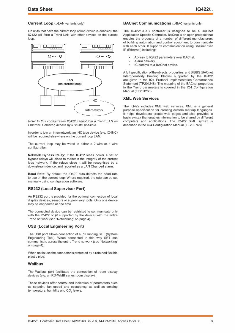
Current Loop (../LAN variants only)
On units that have the current loop option (which is enabled), the IQ422 will form a Trend LAN with other devices on the current loop.
Internetwork
LAN (on current loop)
INC
Note: In this configuration IQ422 cannot join a Trend LAN on Ethernet. However, access by IP is still possible.
In order to join an internetwork, an INC type device (e.g. IQ4NC)will be required elsewhere on the current loop LAN.
The current loop may be wired in either a 2-wire or 4-wire configuration.
network Bypass Relay: If the IQ422 loses power a set of bypass relays will close to maintain the integrity of the current loop network. If the relays close it will be recognised by a downstream device, and reported as a LAN Changed alarm.
Baud Rate: By default the IQ422 auto-detects the baud rate to use on the current loop. Where required, the rate can be set manually using configuration software.
RS232 (Local Supervisor Port)
An RS232 port is provided for the optional connection of local display devices, sensors or supervisory tools. Only one device may be connected at one time.
The connected device can be restricted to communicate only with the IQ422 or (if supported by the device) with the entire Trend network (see ‘Networking’ on page 4).
USB (Local engineering Port)
The USB port allows connection of a PC running SET (System Engineering Tool). When connected in this way SET can communicate across the entire Trend network (see ‘Networking’ on page 4).
When not in use the connector is protected by a retained flexible plastic plug.
Wallbus
The Wallbus port facilitates the connection of room display devices (e.g. an RD-WMB series room display).
These devices offer control and indication of parameters such as setpoint, fan speed and occupancy, as well as sensing temperature, humidity and CO2 levels,
BaCnet Communications (../BAC variants only)
The IQ422/../BAC controller is designed to be a BACnet Application Specific Controller. BACnet is an open protocol that enables the products of a number of different manufacturers of building automation and control equipment to communicate with each other. It supports communication using BACnet over IP (Ethernet) including:
Access to IQ422 parameters over BACnet, Alarm delivery, IC comms to a BACnet device.
A full specification of the objects, properties, and BIBBS (BACnet Interoperability Building Blocks) supported by the IQ422 are given in the IQ4 Protocol Implementation Conformance Statement (TP201248). The mapping of the BACnet properties to the Trend parameters is covered in the IQ4 Configuration Manual (TE201263).
XmL Web Services
The IQ422 includes XML web services. XML is a general purpose specification for creating custom markup languages. It helps developers create web pages and also provides a basic syntax that enables information to be shared by different computers and applications. The IQ422 XML syntax is described in the IQ4 Configuration Manual (TE200768).
4 IQ422/.. Controller Data Sheet TA201260 Issue 6, 14-Oct-2015. Applies to v3.30.
IQ422/.. Data Sheet
networking
In order to connect to the Trend network the IQ422 will create its own internal LAN which includes the following nodes:
a CNC for its own controller, a supervisor CNC (sCNC1) for its RS232 port, a supervisor CNC (sCNC2) for its USB port, three virtual CNCs (vCNC1, vCNC2 and vCNC3), and a virtual INC (vINC).
LAN
IQ422
Web Browser SET
vINC vCNC1
vCNC2 vCNC3
CNC sCNC1 sCNC2
IQ4 control
Supervisor /Tool
US
B
RS
232Ethernet
Supervisor /Tool
Default CnC addressing: The IQ422 device (outstation)address is factory-set (in the Address module) as follows:
Local Lan set to 20;Local address set on a rolling basis in the range 11 to 119, so that in a batch of IQ422s, each will have a different default address (printed on the unit’s serial label).
sCnC1 Functionality: If the RS232 port address is set to 0 (default), sCNC1 is disabled and a connected device can only communicate with the IQ422. If the address is configured to be non-zero, sCNC1 is enabled with that address on the LAN and allows a connected device to communicate with the entire Trend network.
sCnC2 Functionality: When a PC running SET is connected to the USB port it uses sCNC2. If the USB port address is set to 0 (default), sCNC2 is dynamically created at address 125 for the duration of the SET session. When the PC is removed sCNC2 times out and no longer exists on the network. If the address is configured to be non-zero, sCNC2 remains on the network at all times.
vCnC Functionality: Allows a supervisor tool/display to make a permanent connection to the Trend network using TCP/IP. . By default all three vCNCs are disabled.
vInC Functionality: When the IQ422 joins a LAN on Ethernet, the controller with the lowest IP address assumes INC functionality (using its vINC at address 126); any vINCs in other controllers on that LAN will automatically be disabled. The vINC does not exist on a current loop LAN.
IC Comms: The IQ422 can communicate with other IQ controllers and BACnet devices (/BAC variants only) using IC Comms. Some controllers running earlier versions of firmware may not support all IC Comms types. See ‘Compatibility’ on page 9.
HaRDWaRe
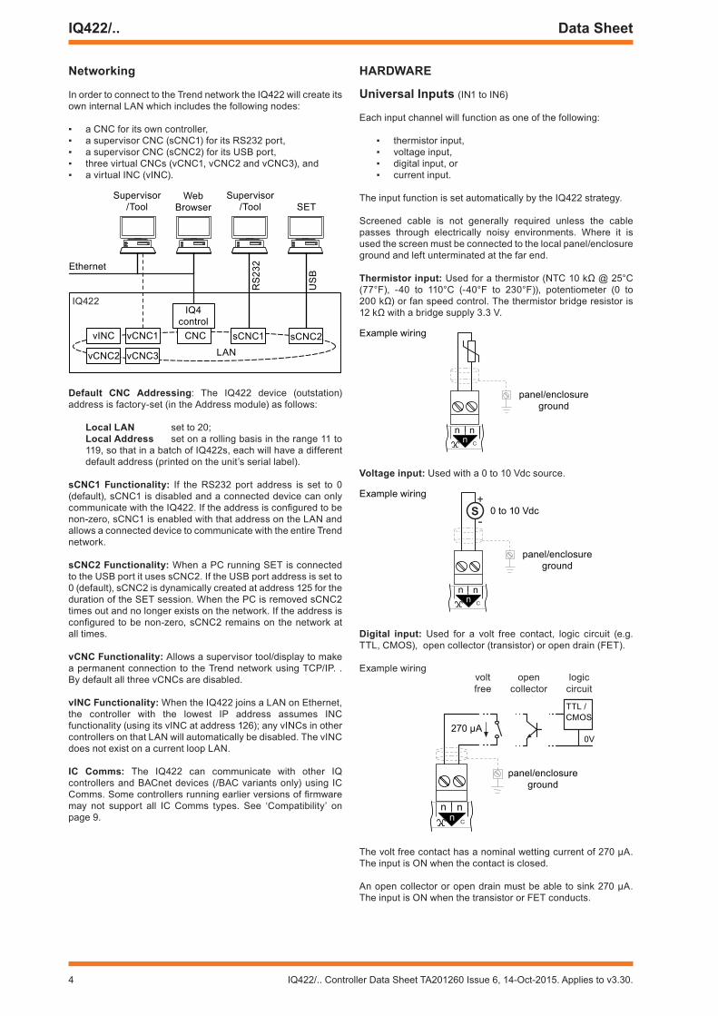
Universal Inputs (IN1 to IN6)
Each input channel will function as one of the following:
thermistor input, voltage input, digital input, or current input.
The input function is set automatically by the IQ422 strategy.
Screened cable is not generally required unless the cable passes through electrically noisy environments. Where it is used the screen must be connected to the local panel/enclosure ground and left unterminated at the far end.
Thermistor input: Used for a thermistor (NTC 10 kΩ @ 25°C (77°F), -40 to 110°C (-40°F to 230°F)), potentiometer (0 to 200 kΩ) or fan speed control. The thermistor bridge resistor is 12 kΩ with a bridge supply 3.3 V.
Example wiring
panel/enclosure ground
Voltage input: Used with a 0 to 10 Vdc source.
S+
-
panel/enclosure ground
0 to 10 Vdc
Example wiring
Digital input: Used for a volt free contact, logic circuit (e.g. TTL, CMOS), open collector (transistor) or open drain (FET).
Example wiring
panel/enclosure ground
voltfree
opencollector
logiccircuit
270 μA
TTL / CMOS
0V
The volt free contact has a nominal wetting current of 270 μA. The input is ON when the contact is closed.
An open collector or open drain must be able to sink 270 μA. The input is ON when the transistor or FET conducts.

IQ422/.. Controller Data Sheet TA201260 Issue 6, 14-Oct-2015. Applies to v3.30. 5
Data Sheet IQ422/..
A logic circuit must be able to sink 270 μA. The input will be ON when the voltage present on the input terminal is less than 2 Vdc (minimum 0 V). A voltage greater than 3.5 Vdc (maximum 50 Vdc) or open circuit will turn the input OFF. Voltage levels between 2 and 3.5 Vdc may cause indeterminate operation.
Current input: Used for 0 to 20 mA sources which can be externally powered or loop powered (from the Auxiliary Supply Output, i.e. one of the AUX terminals).
Example wiring
+V
AUX
S Spanel/enclosure ground
Externally poweredLoop powered
External Power Supply
Auxiliary Output Supply
analogue outputs (OUT7 to OUT12)
These provide a variable control voltage between 0 and 10 Vdc. The output can source up to 20 mA (see “Combined Supply”) and sink up to 3 mA.
If screened cable is used the screen must be connected to the panel/enclosure ground and unterminated at far end.
Example wiring
n
LOA
D
0 to 10 V
panel/enclosure ground
auxiliary Supply output
This output can be used to supply I/O devices (e.g. sensors). It provides 20 Vdc ±10% from AUX terminals 70, 71 and 72, with a return through terminal 73 or any ‘C’ terminal.
The arrangement of internal fuses and the maximum current from each terminal depends on the input power supply:
Input Power Supply
auxiliary output (aUX) Terminals70 71 72
/230 120 mA shared 120 mA
/24VaC 240 mA* shared
*For operating temperatures above 40°C the maximum current must not exceed 200 mA.
Combined Supply
The IQ422’s combined supply provides power for the:
Analogue outputs, Auxiliary supply output, Wallbus, RS232 port, and USB port.
If the total power requirement of the combined supply is more than the controller can provide it will be necessary to power some of the items using external power sources.
Note: On /24VAC versions the maximum combined supply current is 400 mA. Exceeding 240 mA may cause the auxiliary supply output voltage to fall below specification.
For further details on calculating the available current from the combined supply, see the IQ4 Configuration Manual (TE201263).
enclosure
The IQ422 is housed in a polycarbonate case. Integral spring clips on the back of the case enable the unit to be clipped on to (and quickly released from) a standard TS35 DIN rail.
The /230 version must be installed in a secondary enclosure with a minimum protective rating of IP20 (or equivalent).
The /24VaC version must be installed in a secondary enclosure with a minimum protective rating of IP20 (or equivalent) or mounted outside normal reach (e.g. in a plenum)
The unit may be mounted horizontally or vertically but not upside down or on its back:
IQ4
22
IQ422
For /230 maximum operating temperature 40 °C (104 °F)
power terminals
IQ422
IQ4
22
DIN rail end stop
Rotating clear polycarbonate covers provide access for the power, communications and I/O connections.
Input Power Supply
The IQ422 has both 230 Vac and 24 Vac input power options.
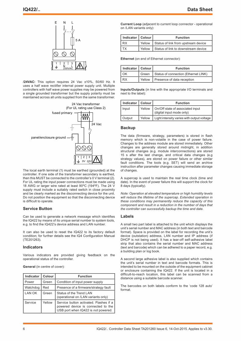
/230: This option requires 230 Vac ±10%, 50/60 Hz. The input power earth (ground) terminal is isolated from the input power neutral, and must be separately earthed (grounded) locally; this ground terminal is internally connected to the IQ422 electronics earth (ground).
The 230 V supply must include a dedicated 5 A fuse complying with IEC60269 (BS1362) and a suitably rated switch in close proximity and be clearly marked as the disconnecting device for the unit. A 5 A circuit breaker with high breaking capacity may be used as an alternative.
6 IQ422/.. Controller Data Sheet TA201260 Issue 6, 14-Oct-2015. Applies to v3.30.
IQ422/.. Data Sheet
2 V30 AC
N L
1 2 3
5 A
N LE
/24VaC: This option requires 24 Vac ±10%, 50/60 Hz. It uses a half wave rectifier internal power supply unit. Multiple controllers with half wave power supplies may be powered from a single grounded transformer but the supply polarity must be maintained across all units supplied from the same transformer.
panel/enclosure ground
24 Vac
24 Vac transformer(For UL rating use Class 2)
fused primary
The local earth terminal (1) must be earthed (grounded) at the controller. If one side of the transformer secondary is earthed, then this MUST be connected to the controller’s 0 V terminal (2).For UL rating the input power connections must be made using 18 AWG or larger wire rated at least 90ºC (194ºF). The 24 V supply must include a suitably rated switch in close proximity and be clearly marked as the disconnecting device for the unit. Do not position the equipment so that the disconnecting device is difficult to operate.
Service Button
Can be used to generate a network message which identifies the IQ422 by means of its unique serial number to system tools, e.g. to find the IQ422’s device address and LAN number.
It can also be used to reset the IQ422 to its factory default condition; for further details see the IQ4 Configuration Manual (TE201263).
Indicators
Various indicators are provided giving feedback on the operational status of the controller.
General (in centre of cover):
Indicator Colour FunctionPower Green Condition of input power supply
Watchdog Red Presence of a firmware/strategy fault
LAN OK Green Status of the Trend LAN(operational on /LAN variants only)
Service Yellow Service button activated. Flashes if a powered device is connected to the USB port when IQ422 is not powered.
Current Loop (adjacent to current loop connector - operational on /LAN variants only):
Indicator Colour FunctionRX Yellow Status of link from upstream device
TX Yellow Status of link to downstream device
ethernet (on end of Ethernet connector):
Indicator Colour FunctionOK Green Status of connection (Ethernet LINK)
RX Yellow Presence of data reception
Inputs/outputs (in line with the appropriate I/O terminals and next to the label):
Indicator Colour FunctionInput Yellow On/Off state of associated input
(digital input mode only)
Output Yellow Light intensity varies with output voltage
Backup
The data (firmware, strategy, parameters) is stored in flash memory which is non-volatile in the case of power failure. Changes to the address module are stored immediately. Other changes are generally stored around midnight, in addition structural changes (e.g. module interconnections) are stored 15 s after the last change, and critical data changes (e.g strategy values), are stored on power failure or other similar fault conditions. The tools (e.g. SET) will send an archive instruction after parameter changes causing immediate storage of changes.
A supercap is used to maintain the real time clock (time and date). In the event of power failure this will support the clock for 8 days (typically).
Note: Operation at elevated temperature or high humidity levels will reduce the lifetime of the supercap. Extended operation in these conditions may permanently reduce the capacity of this component and result in a reduction in the number of days that the controller can successfully backup the time and date.
Labels
A small two part label is attached to the unit which displays the unit’s serial number and MAC address (in both text and barcode format). Space is provided on the label for recording the unit’s device (outstation) address, LAN number and IP address (if DHCP is not being used). It has a tear-off self-adhesive label strip that also contains the serial number and MAC address (text and barcode) which can be adhered to a paper record, e.g. a building plan or log book.
A second large adhesive label is also supplied which contains the unit’s serial number in text and barcode formats. This is intended to be mounted on the outside of the equipment cabinet or enclosure containing the IQ422. If the unit is located in a difficult-to-reach location, this label can be scanned from a distance using a suitable barcode scanner.
The barcodes on both labels conform to the ‘code 128 auto’ format.

IQ422/.. Controller Data Sheet TA201260 Issue 6, 14-Oct-2015. Applies to v3.30. 7
Data Sheet IQ422/..
FIRmWaRe
The firmware in the IQ422 controls its basic functionality and provides a range of modules that can be configured to produce a control strategy.
modules
The range of modules provided in the IQ422 firmware are listed in the table below. Full details of each module can be found in the IQ4 Configuration Manual (TE201263).
module brIQs max. number of modules noteAddress 24 1 (fixed)
Alarm Destination
14 (8)
Alarm Group 9 500Alarm Route 9 500Alarm Log 0 1 (fixed)
Analog Node 16 510Digital Byte 16 1012Digital Input 28 1500
Directory 13 500Display 19 1500Driver 57 500
Function 19 1000
IC Comms 19 250
Interface 130 500
Knob 13 1500Logic 19 1000
Loop 55 500Network 0
NTD 30 limited by max. brIQs onlyOption 0
OSS 34 500Page 4 500Plot 12 500Program 0 1 (fixed)
Schedule Offset 21 500Sensor 76 1500
Sensor type 12 99Sequence 106 1 (fixed) (600 steps)Switch 10 1500Time 38 1 (fixed)Time Schedule 566 100
User 12 500Virtual CNC 9 3
Notes: The number of brIQs used on these modules varies with
the module type. The largest size is shown here.The Time Schedule module brIQ count given here allows for
20 exceptions. Further exceptions requires 13 brIQs each. These modules are always present in the IQ422. Additional 5 brIQs required per input and output.
The quantity of each type of module may be adjusted to match the requirements of the application subject to the following:
A maximum of 4000 modules in total, A maximum for each type of module, and The IQ422’s memory capacity (16,000 ‘brIQs’).
The maximum number of modules for each type, and the number of brIQs required per module are shown in the table above.
Plot modulesThe IQ422’s Plot modules can plot any connectable module output (analogue or digital). There are four types of Plot module: synchronised, triggered, periodic and COV (change of value). Although all four types are BACnet interoperable, only periodic plots can be compliant with the BACnet standard. All Plot modules can generate a buffer ready alarm when the number of records equals a notification threshold.
The maximum number of records per plot is 1000. The maximum total number of records (for all plots) depends on the available plot memory (measured in log points) and the type of plots used - each synchronised plot record requires 5 log points, while each triggered, COV or periodic plot record requires 10 log points:
maximum plot memory (log points)
max. number of recordssynchronised
plotstriggered, COV or periodic plots
1,000,000 200,000 100,000
Note: A maximum of 100 plots can be serviced in a 1 s period (e.g. 100 x 1 s plots only). This is calculated on the average plots serviced in 1 s, so a 1 minute plot would contribute a 1/60. For example 90 x 1 s plots plus 360 x 1 min would give 96 (90+6) plots per second on average. The periodic and triggered plots must also be counted and it’s up to the engineer to make his best estimate.
Firmware Upgrades
New versions of firmware may be made available from time to time to change or add functionality or to provide support for new products.
Firmware can be upgraded using a PC running the IQTool Firmware Upgrade Applet, and to the IQ422 connected over Ethernet (recommended for speed) or the Trend current loop.

8 IQ422/.. Controller Data Sheet TA201260 Issue 6, 14-Oct-2015. Applies to v3.30.
IQ422/.. Data Sheet
The web interface does not allow the strategy structure to be modifi ed (e.g. changing module interconnections, adding or deleting modules).
Graphical display pages (GraphIQs), which are confi gured using IQ422’s display and directory modules, can also be accessed.
For further details of web pages see the IQ4 Confi guration Manual (TA201263), the IQ4 Web User Guide (TC201256), and the Graphical Display Pages Editor Manual (TE200629).
Language
The user can specify which language the IQ422 uses for the display of web pages and for transmitted alarms. The standard languages are in the controller as supplied. In the controller the Address module has a language parameter which will be set to the default language, but can be changed to any one of the other available languages. The IQ422 can use languages which require 8 bit code (i.e. special or accented characters) and can also operate with right to left languages (e.g. Chinese, Arabic).
Identifi cation
The IQ422 will identify itself as an IQ4 to w comms.
STRaTeGy
In order to operate as a controller, the modules provided by the fi rmware must be confi gured to defi ne the way the controller is to control the connected equipment. This confi guration is known as the strategy. Strategies are confi gured using the System Engineering Tool (SET).
This produces a strategy fi le (fi lename.IQ4) that can be downloaded to the controller to defi ne its operation. This fi le consists of all the strategy module instances, their parameters, and links. When this is downloaded it is stored in the controller and then run using the controller fi rmware.
For details of using SET see the System Engineering Tool Manual (TE200147).
Timemaster
The IQ422 can act as a system Timemaster to synchronise the time and date across the Trend system. It can use SNTP (simple network time protocol) to obtain precision current time from an unauthenticated NTP server on the Internet. Daylight saving can be implemented automatically (via timezone setting) or manually by specifi ed dates and time adjustment.
alarms
The IQ422 will generate Network, General, and Item alarms. Network alarms are generated by the Trend Network nodes, General alarms are generated when the IQ422 detects a problem within its own hardware or program, and Item alarms are generated by the strategy, and are normally due to a faulty plant condition.
Network alarms are sent to supervisors or tools connected to the RS232 local supervisor port, USB local engineering port, or to one of the controller’s vCNCs.
General and Item alarms can be sent either to a designated Trend LAN address, to an IP address, or as an email. Alternatively, certain Item alarms (sensor, digital input, digital driver readback, and plot), can be sent to a BACnet device.
Alarms sent to a Trend LAN address, or to an IP address can either be sent in text, coded, or attribute format. Network alarms are sent in text format only.
For coded alarms the protocol limits the item number to 255 maximum. For text alarms the maximum item label length is 20 characters (although the 963 can be set up to use labels previously learnt).
Sending an alarm by email requires the Email Server Address to be set up in the address module. The Email Server Address can be an IP address, an internet domain name, or a host name; the internet domain name or host name require a DNS server address or a WINS server address respectively to be set up in the network module so that the name can be resolved.
All alarms (except Network alarms) are also stored locally in the Alarm Log. The alarm log can record up to 300 alarms. Once this limit is reached each new alarm will overwrite the oldest record.
Web Pages
An integral web interface can be accessed over an Ethernet/IP connection using a Web browser on a PC, tablet or smartphone.
Access can be restricted by entry of a valid user name and password. Once connection to the controller has been made, it is possible to view and adjust occupation times, view the alarm log, and view/adjust/graph individual module parameters.
IQ422/.. Controller Data Sheet TA201260 Issue 6, 14-Oct-2015. Applies to v3.30. 9
Data Sheet IQ422/..
FIeLD maInTenanCeThe IQ422 requires no routine maintenance.
DISPoSaLCOSHH (Control of Substances Hazardous to Health - UK Government Regulations 2002) ASSESSMENT FOR DISPOSAL OF IQ422.
RECYCLING .All plastic and metal parts are recyclable. The printed circuit board may be sent to any PCB recovery contractor to recover some of the components for any metals such as gold and silver.
Weee Directive:
At the end of their useful life the packaging, and product should be disposed of by a suitable recycling centre.
Do not dispose of with normal household waste.Do not burn.
ComPaTIBILITyBrowsers: This device has been successfully tested with Internet Explorer (v10 & 11), Chrome (v29.0.1547.0), Mozilla Firefox (v23), Safari (v5.1.7) and with the default browser on the following device operating systems:
Apple iOS 8.1.3Android 5.0 ‘Lollipop’Windows Phone 8.1
It should work with all modern browsers, smart phones, and tablets (with JavaScript enabled) available at the date of release of this product.
Owing to the rapidly changing nature of web devices, new devices and browsers will become available after the release of this product. If you would like to check the compatibility of IQ422 with your device, please connect to: iq4demo.trendcontrols.com. Log in with username: mobile and password: trend.
Supervisors and Displays: 963 v3.5 or greater, 916, IQView, IQView4, IQView8, RD-IQ, SDU-xcite.
Note: The NDP is not compatible with IQ422; it will not recognise an IQ422 connected to its network.
Wallbus: RD-WMB, RS-WMB, RV-WMB.
tility software: SET v7.0 or greater
IC Comms: IQ4, IQ3, IQ2, IQeco, IQL, and IQ1 (v3 onwards).
Note: Some controllers running earlier versions of firmware may not support all IC Comms types. Refer to the IQ4 Configuration Manual (TE201263) for full compatibility details. For details on using IC Comms with IQL controllers refer to the Trend LonWorks Products Engineering Manual (TE200292).
Controllers: IQ3/IQ4 directly and IQ1, IQ2, IQL by way of XTEND. IQ422/LAN communicates with IQ2, IQ1 directly. IQeco by way of IQ4NC.
Strategies: IQ1, IQ2, IQ3 can be imported into SET, converted into IQ4 strategies, and then downloaded into an IQ422. If the strategy file accesses I/O channels beyond those available in the IQ422 the strategy will be rejected.
ethernet nodes: XTEND, NXIP, or EINC.
Note: NXIP or EINC must not be used in an automatic IP addressing (DHCP) environment.
BaCnet Devices: (/BAC variants only). The IQ422 controller is certified as a BACnet Application Specific Controller (B-ASC), for details of the certification go to:
http://www.bacnetinternational.net/btl/index.php?m=52.
Compatibility is defined in IQ4 Product Implementation Conformance Statement (TP201248).
InSTaLLaTIonThe IQ422 is designed to be clipped on to a standard TS35 DIN rail. The /230 version must be installed in a secondary enclosure with a minimum protective rating of IP20 (or equivalent). The /24VAC version should be installed in an enclosure or outside normal reach (e.g. in a plenum). All /24VAC controllers are UL rated as ‘UL916 listed open energy management equipment’.
The installation procedure involves:
!WaRnInG: Contains no serviceable parts. Do not attempt to open the unit. Failure to comply may cause damage to the unit.
Mounting the controller in positionConnecting powerConnecting Ethernet (if required)Connecting RS232 (if required)Connecting Current Loop (../LAN only)Connecting the I/O channels (as required)Connecting Wallbus (if required)Powering upSetting up IP address parameters (if required)
Setting up LAN number and device addressChecking networkConfiguring the strategyTesting strategy using controller simulation in SETDownloading strategy and other configuration filesCheck BACnet communications (../BAC only)Connecting inputs and checking operationConnecting outputs and checking operation
A full description of installing the unit is given in the IQ422 Installation Instructions - Mounting (TG201264) and IQ422 Installation Instructions - Configuring (TG201265).
10 IQ422/.. Controller Data Sheet TA201260 Issue 6, 14-Oct-2015. Applies to v3.30.
IQ422/.. Data Sheet
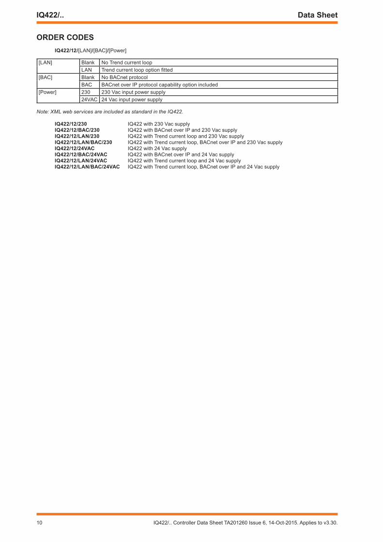
oRDeR CoDeSIQ422/12/[LAN]/[BAC]/[Power]
[LAN] Blank No Trend current loopLAN Trend current loop option fitted
[BAC] Blank No BACnet protocolBAC BACnet over IP protocol capability option included
[Power] 230 230 Vac input power supply24VAC 24 Vac input power supply
Note: XML web services are included as standard in the IQ422.
IQ422/12/230 IQ422 with 230 Vac supplyIQ422/12/BaC/230 IQ422 with BACnet over IP and 230 Vac supplyIQ422/12/Lan/230 IQ422 with Trend current loop and 230 Vac supplyIQ422/12/Lan/BaC/230 IQ422 with Trend current loop, BACnet over IP and 230 Vac supplyIQ422/12/24VaC IQ422 with 24 Vac supplyIQ422/12/BaC/24VaC IQ422 with BACnet over IP and 24 Vac supplyIQ422/12/Lan/24VaC IQ422 with Trend current loop and 24 Vac supplyIQ422/12/Lan/BaC/24VaC IQ422 with Trend current loop, BACnet over IP and 24 Vac supply
IQ422/.. Controller Data Sheet TA201260 Issue 6, 14-Oct-2015. Applies to v3.30. 11
Data Sheet IQ422/..
SPeCIFICaTIonSeLeCTRICaL
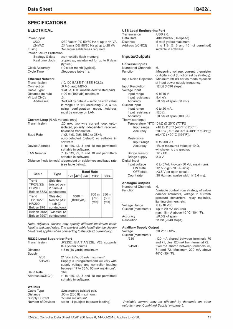
Power Input/230 :230 Vac ±10% 50/60 Hz at up to 44 VA/24VAC :24 Vac ±10% 50/60 Hz at up to 28 VA
Fusing :No replaceable fuses required.Power Failure Protection
Strategy & data :non-volatile flash memory.Real time clock :supercap, maintained for up to 8 days
(typical).Clock Accuracy :10 s per month (typical).Cycle Time :Sequence table 1 s.
ethernet networkTransmission :10/100 BASE-T (IEEE 802.3).Connection :RJ45, auto MDI-X.Cable Type: :Cat 5e, UTP (unshielded twisted pair).Distance (to hub) :100 m (109 yds) maximumVirtual CNCs :3.
Addresses :Not set by default – set to desired value in range 1 to 119 (excluding 2, 3, & 10) using configuration mode. Address must be unique on LAN.
Current Loop (/LAN variants only)Transmission :20 mA, two wire current loop, opto-
isolated, polarity independent receiver, balanced transmitter.
Baud Rate :1k2, 4k8, 9k6, 19k2 or 38k4; auto-detected (default) or settable in
software.Device Address :1 to 119, (2, 3 and 10 not permitted)
settable in software.LAN Number :1 to 119, (2, 3 and 10 not permitted)
settable in software. Distance (node to node) :dependent on cable type and baud rate
(see table below):
Cable TypeBaud Rate
1k2 4k8 9k6 19k2 38k4Trend TP/2/2/22/HF/200Belden 8723
Shielded twisted pair2 pairs (4 conductors)
1000 m(1090 yds)
700 m(765 yds)
350 m(380 yds)
Trend TP/1/1/22/HF/200Belden 8761
Shielded twisted pair1 pair (2 conductors)
Belden 9182Belden 9207
Twinaxial (2 conductors)
Note: Adjacent devices may specify different maximum cable lengths and baud rates. The shortest cable length (for the chosen baud rate) applies when connecting to the IQ422 current loop.
RS232 Local Supervisor PortTransmission :RS232, EIA/TIA/232E, V28 supports
IQ System commsDistance :15 m (16 yards) maximumSupply
/230 21 Vdc ±5%; 60 mA maximum*/24VAC Supply is unregulated and will vary with
supply voltage and controller loading between 17 to 35 V; 60 mA maximum*.
Baud Rate :9k6.Address (sCNC1) :1 to 119, (2, 3 and 10 not permitted)
settable in software.
WallbusCable Type :Unscreened twisted pair.Distance :60 m (200 ft) maximum.Supply Current :50 mA maximum*.Number of Devices :up to 14 (subject to power loading)
USB Local engineering PortTransmission :USB 2.0.Data Rate :480 Mbits/s (Hi-Speed)Distance :5 m (5 yards) maximum.Address (sCNC2) :1 to 119, (2, 3 and 10 not permitted)
settable in software.
Inputs/outputs
Universal Inputs Number of Channels :6.Function :Measuring voltage, current, thermistor
or digital input (function set by strategy).Input Noise Rejection :Minimum 60 dB series mode rejection
at input power supply frequency.Input Resolution :12 bit (4096 steps).Voltage Input
Input range :0 to 10 V.Input resistance :9.4 kΩ.Accuracy :±0.5% of span (50 mV).
Current InputInput range :0 to 20 mA.Input resistance :120 Ω.Accuracy :±0.5% of span (100 μA).
Thermistor Input Temperature (NTC 10 kΩ @ 25°C (77°F))
Input range :-40 to 110°C (-40°F to 230°F)Accuracy :±0.3°C (-40°C to 90°C (-40°F to 194°F)); ±0.4°C (> 90°C (194°F)).
ResistanceInput range :0 to 200 kΩAccuracy :1% of measured value or 10 Ω,
whichever is the greater.Bridge resistor :12.2 kΩ.Bridge supply :3.3 V.
Digital Input Input voltage :0 to 5 Vdc typical (50 Vdc maximum).
ON state :<2.5 V @ 270 µA (sink).OFF state :>3.5 V (or open circuit).
Count rate :30 Hz max. (pulse width ≥16.6 ms).
analogue outputsNumber of Channels :6.Function :Variable control from strategy of valve/
damper actuators, voltage to current/pressure converters, relay modules, lighting dimmers, etc.
Voltage Range :0 to 10 Vdc.Current (maximum*) :up to 20 mA (source).
max. 18 mA above 40 °C (104 °F).Accuracy :±0.5% of span.Resolution :11 bit (2048 steps).
auxiliary Supply output Voltage :20 Vdc ±10%. Current (maximum*)
/230 :120 mA shared between terminals 70 and 71, plus 120 mA from terminal 72.
/24VAC :240 mA shared between terminals 70, 71 and 72. Maximum 200 mA above 40°C (104°F).
*Available current may be affected by demands on other outputs - see ‘Combined Supply’ on page 5.
12 IQ422/.. Controller Data Sheet TA201260 Issue 6, 14-Oct-2015. Applies to v3.30.
IQ422/.. Data Sheet
Please send any comments about this or any other Trend technical publication to [email protected]
© 2015 Honeywell Technologies Sàrl, ECC Division. All rights reserved. Manufactured for and on behalf of the Environmental and Combustion Controls Division of Honeywell Technologies Sàrl, Z.A. La Pièce, 16, 1180 Rolle, Switzerland by its Authorized Representative, Trend Control Systems Limited.
Trend Control Systems Limited reserves the right to revise this publication from time to time and make changes to the content hereof without obligation to notify any person of such revisions or changes.
Trend Control Systems LimitedAlbery House, Springfield Road, Horsham, West Sussex, RH12 2PQ, UK. Tel:+44 (0)1403 211888 Fax:+44 (0)1403 241608 www.trendcontrols.com
SPeCIFICaTIonS (continued)
InDICaToRS
Power ( ) :Green LEDWatchdog ( ) :Red LEDLAN OK ( ) :Green LEDService Button ( ) :Yellow LEDRX (current loop) :Yellow LEDTX (current loop) :Yellow LEDOK (Ethernet) :Green LEDRX (Ethernet) :Yellow LEDIN1 to IN6 :Yellow LEDOUT7 to OUT12 :Yellow LED
meCHanICaL
Dimensions (WxHxD) :116 mm (4.57”) x 157.5 mm (6.2”) x 58.5 mm (2.3”).
MaterialMain body :Flame Retardant Polycarbonate (white)Terminal covers :Flame Retardant Polycarbonate
(translucent orange).Weight
/24VAC :0.380 kg (0.83 lb)/230 :0.415 kg (0.91 lb)
Mounting :TS35 DIN Rail (EN500022).
ConnectorsPower
Connector type :2 part connector with rising cage clamp screw terminals.
Cable size :0.14 to 2.5 mm2 (22 to 12 AWG). For UL compliance the input power connections must be made using 18 AWG or larger wire rated at least 90°C (194 °F).
Inputs/Outputs, Current Loop, Wallbus & AUX (power out)Connector type: :2 part connector (0.2” pitch) with rising
cage clamp screw terminals.Cable size :0.14 to 2.5 mm2 (22 to 12 AWG)
For UL compliance use copper cable only.
RS232 Supervisor Port :RJ11 (FCC68).Ethernet Port :RJ45 connector.USB Engineering Port :Micro B connector.USB Expansion Port :USB Type A (for future use)
enVIRonmenTaL
EMC :EN61326-1:2006.Immunity :Table 2 - for equipment intended for
use in industrial locations.Emissions :Class B.
Safety :EN61010-1:2010.CB certificates
/230 :NO80024/24VAC :NO80023
USA/Canada :IQ422/24VAC variants are UL rated as ‘UL916 listed open energy management equipment’
Canada :CSA22.2 No. 205-M1983 - Signal Equipment.
Ambient LimitsStorage :-25°C (-13°F) to +60°C (+140°F).Operating :-25°C (-13°F) to +55°C (+131°F).
Note: For /230 variants mounted vertically with the power connector end at the top the maximum operating temperature is 40°C (104°F) - see page 5. For temperatures below 0°C (32°F) special care must be taken that there is no condensation on or within the unit.
Humidity :0 to 90% RH non-condensing.Altitude :<4000 m (13124’).Pollution Degree :2 (Only non-conducting pollution
occurs).Protection
/230 :IP20 if mounted in an enclosure rated at IP20 or equivalent.
/24VAC :IP20..
iPad and iPhone are trademarks of Apple Inc., registered in the U.S. and other countries. Android is a trademark of Google Inc. Windows is either a registered trademark or trademark of Microsoft Corporation in the United States and/or other countries