Embed Size (px)
Citation preview

IQ-P-001-A
Québec Balancing Authority Area Procedure
Maximum Real and Reactive Power Verification
at Generation Facilities of 50 MVA or Higher Capacity
May 9, 2014

HI
Québec Balancing Authority Area Procedure
Page 1 of 26
Title Number
IQ-P-001-A
Revised version
yes no
Replaces procedure IQ-P-001-A (2010-10-18)
Effective date
Maximum Real and Reactive Power Verification at Generation Facilities of 50 MVA or Higher Capacity
2014-05-09
Issued to
Generator Owners and Generator Operators in the Québec Balancing Authority Area
Drafted by Modified by Verified by Approved by
Martin Boisvert
Sophie Gagnon, Eng.
Caroline Dupuis, Eng.
Pierre Paquet
TABLE OF CONTENTS
PURPOSE ...............................................................................................................................................................3 1. APPLICATION........................................................................................................................................................3 2. COMPLIANCE ........................................................................................................................................................3 3. CONFIDENTIALITY OF DATA ...........................................................................................................................3 4. VERIFICATION CONDITIONS ...........................................................................................................................3
4.1. WIND FARMS .....................................................................................................................................3 4.2. HYDROELECTRIC GENERATING STATIONS, THERMAL PLANTS AND GAS-FIRED PLANTS ............3
4.2.1. The Generator Owner’s and the Generator Operator's responsibilities...................................................4 4.2.2. Station test ..............................................................................................................................................4 4.2.3. Unit test 4 4.2.4. Test duration ...........................................................................................................................................4 4.2.5. Waiver request for conducting the station test........................................................................................5 4.2.6. Other test constraints ..............................................................................................................................5
4.3. EXEMPTIONS .....................................................................................................................................6 4.3.1. Generation facilities with a capacity less than 50 MVA.........................................................................6 4.3.2. Station tests in the summer period..........................................................................................................6 4.3.3. Gross Power............................................................................................................................................6 4.3.4. Other exemptions....................................................................................................................................6
5. TEST PROCEDURE – HYDRO, THERMAL AND GAS-FIRED GENERATING STATIONS.....................7 5.1. SCHEDULING THE TESTS ..................................................................................................................7
5.1.1. Generating stations connected to the Hydro-Québec TransÉnergie transmission system ......................7 5.1.2. Generating stations connected to an auxiliary transmission system and for the Churchill Falls
Generating Station ..................................................................................................................................8 5.2. CONDUCTING THE TESTS..................................................................................................................8
5.2.1. Communications before and during the test ...........................................................................................8 5.2.1.1. Generating stations connected to the Hydro-Québec TransÉnergie transmission system.......8 5.2.1.2. Generating stations connected to an auxiliary transmission system and for the Churchill
Falls Generating Station ..........................................................................................................9 5.2.2. Framework test procedures...................................................................................................................10
5.2.2.1. STATION TEST – Maximum real and reactive power of a generating station ....................10
Direction – Contrôle des mouvements d'énergie

HI
Procedure IQ-P-001-A
Page 2 of 26
5.2.2.2. UNIT TEST – Maximum real and reactive power of each unit at a generating station.........10 5.2.3. Retesting ...............................................................................................................................................11 5.2.4. After testing ..........................................................................................................................................11
5.3. COMMUNICATING RESULTS ...........................................................................................................11 5.4. DISCREPANCIES IN RESULTS ..........................................................................................................11
6. TEST PROCEDURE – WIND FARMS ...............................................................................................................12 6.1. VERIFICATION METHOD.................................................................................................................12 6.2. COMMUNICATING RESULTS ...........................................................................................................12 6.3. DISCREPANCIES IN RESULTS ..........................................................................................................12
7. INABILITY TO ACHIEVE THE DECLARED CAPABILITIES ....................................................................13 8. COMMUNICATING RESULTS OF UNIT TESTS TO HYDRO-QUÉBEC TRANSÉNERGIE..................13 9. CONTACTS............................................................................................................................................................14 10. HISTORY OF UPDATES .....................................................................................................................................15 APPENDIX A PROCESS – SCHEDULING THE TESTS.....................................................................................18 APPENDIX B PROCESS – CONDUCTING THE TESTS ....................................................................................20 APPENDIX C HYDRO-SAGUENAY GENERATING STATIONS – PARTICULAR PROCESS FOR
SCHEDULING AND CONDUCTING THE TESTS.......................................................................22 APPENDIX D STATION TEST – MAXIMUM REAL AND REACTIVE POWER VERIFICATION ............24 APPENDIX E UNIT TEST – MAXIMUM REAL AND REACTIVE POWER VERIFICATION....................25 APPENDIX F PERFORMANCE DATA FOR WIND FARMS ............................................................................26
Direction – Contrôle des mouvements d'énergie

HI
Procedure IQ-P-001-A
Page 3 of 26
Direction – Contrôle des mouvements d'énergie
PURPOSE
The purpose of this Procedure is to provide guidance for verifying the maximum real and reactive power of a generating station (station test) and of each generating unit (unit test), and for compiling the performance data of wind farms.
This must be done in order to update real-time system operations databases and evaluate available resources in the Québec Balancing Authority Area. The results of unit tests help validate official specifications for generating units provided by Generator Owners or Generator Operators and used for system planning, operations studies and steady-state system models.
This verification must comply with the requirements of Hydro-Québec TransÉnergie, particularly with the document Transmission Provider Technical Requirements for the Connection of Power Plants to the Hydro-Québec Transmission System, which sends a letter every year to each Generator Owner and Generator Operator notifying it that verification must be done.
1. APPLICATION
This Procedure applies to the Generator Owners (GOs) and the Generator Operators (GOPs) of generation facilities with a capacity of 50 MVA or more, located in or considered part of the Québec Balancing Authority Area.
2. COMPLIANCE
This Procedure is in compliance with the NERC Reliability Standards TOP-002-2.1b (R13, R14 and R14.1) and VAR-001-3 (R1 and R2), and with the NPCC criteria included in Directories D9 and D10.
3. CONFIDENTIALITY OF DATA
In accordance with the Transmission Provider Code of Conduct and the Reliability Coordinator Code of Conduct, Hydro-Québec TransÉnergie staff participating in this Procedure keep data submitted by GOs and GOPs confidential.
4. VERIFICATION CONDITIONS
4.1. WIND FARMS
Because of the intermittent nature of the wind, 50 MVA or more wind farm GOs or GOPs must submit required data as specified in section 6. Wind-farm performance tracking replaces maximum real and reactive power tests. Also, each GO and GOP is in charge of compiling the performance data and making sure that the criteria in this Procedure are followed.
4.2. HYDROELECTRIC GENERATING STATIONS, THERMAL PLANTS AND GAS-FIRED PLANTS
For hydroelectric generating stations, thermal plants and gas-fired plants, two types of tests are used to verify maximum real and reactive power:
The station test, used to verify the maximum real and reactive power that a generating station can develop under peak conditions;
The unit test, used to verify the characteristics of generating units.

HI
Procedure IQ-P-001-A
Page 4 of 26
4.2.1. The Generator Owner’s and the Generator Operator's responsibilities
Each GO and GOP is in charge of scheduling and conducting the tests and making sure that the criteria in this Procedure are followed.
Although, during the tests, the GO and the GOP may test or measure other generating unit parameters for its own purposes provided this does not change test conditions and does not lead to power variations.
4.2.2. Station test
Since loads on the Hydro-Québec TransÉnergie system are not heavy in summer, the Direction –Contrôle des mouvemenents d'énergie (CMÉ), assuming the role of Transmission Operator for the Québec Balancing Authority Area, specified that station tests must be conducted in the winter period that is from November 1st to February 28th, and every 3 years.
A station test can be conducted outside this period provided that a waiver is granted to the GO or to the GOP by the Direction – CMÉ. Refer to section 4.2.5 for the application details.
The station tests must be conducted for all generating stations with a capacity of 50 MVA or more according to a three-year schedule drawn up by the GOs and the GOPs. The schedule must be revised every year and sent no later than October 31st to:
The Regional Outage Scheduler for generating stations connected to the Hydro-Québec TransÉnergie transmission system;
The System Control Outage Scheduler for generating stations connected to an auxiliary transmission system or for the Churchill Falls Generating Station;
Direction – CMÉ.
4.2.3. Unit test
The unit test can be realized in any period of the calendar year and must be conducted every 5 years or as soon as changes are made that affect the generating unit’s real or reactive power.
The unit tests must be conducted for all generating units of generating stations with a capacity of 50 MVA or more according to a five-year schedule drawn up by the GOs and the GOPs. This schedule must be revised every year and sent no later than December 1st to:
The Regional Outage Scheduler for generating stations connected to the Hydro-Québec TransÉnergie transmission system;
The System Control Outage Scheduler for generating stations connected to an auxiliary transmission system or for the Churchill Falls Generating Station;
Direction – CMÉ.
4.2.4. Test duration
For hydroelectric generating stations, thermal plants and gas-fired plants:
The minimum duration of the station test must be 1 hour 15 minutes; The minimum duration of the unit test must be 1 hour 15 minutes.
Direction – Contrôle des mouvements d'énergie

HI
Procedure IQ-P-001-A
Page 5 of 26
4.2.5. Waiver request for conducting the station test
A station test can be conducted outside the winter period provided that a waiver is granted to the GO or to the GOP by the Direction – CMÉ.
A waiver request can be submitted by the GO or the GOP to the Direction – CMÉ if the following conditions are met:
Permanent conditions so that it is impossible to achieve the maximum power of the generating station when conducting the station test in the winter period, as is required in section 5.2.2.1;
Possibility of conducting the station test of the generating station outside the winter period and achieve the maximum power of this generating station, as is required in section 5.2.2.1.
The waiver request shall be submitted with the following information:
1. Generating station for which a waiver request is made. 2. Identification of the winter period for which a waiver request is done. 3. Proposition of a different period for conducting the station test of the generating station.
The waiver request must be submitted by the GO or the GOP to the Direction – CMÉ no later than October 31st before the date scheduled for conducting the station test of the generating station.
The Direction – CMÉ must, within 30 days following receipt of the waiver request from the GO or the GOP, notify the latter of the acceptance or the refusal of the request.
4.2.6. Other test constraints
1. Maximum real and reactive powers are tested in compliance with any operating restrictions which may apply to generating stations, generating units or related equipment. Operating constraints to prevent damage to generating units (e.g., on axial pulsing, vibrations and temperature) must not be exceeded.
2. Testing must not lead to contravening operating criteria (e.g., minimum operating reserves, maximum power flows, acceptable voltage ranges for equipment). Testing may be limited or interrupted at the request of a System Control Dispatcher should a system limit be reached and transmission system reliability compromised.
3. The maximum real and reactive powers tests of hydroelectric generating stations with interdependent water levels or flows potentially affecting the results must be tested at the same time.
4. The maximum real and reactive powers tests of generating stations, whose the reactive power generation mutually affect each other, depending on the maximum voltage of their common collector system, must be tested at the same time.
5. It is preferable that generating stations or units capable of being islanded to a neighboring system be tested when the generating units are synchronized to the Québec grid. If that is not possible, the System Control Outage Scheduler or System Control Dispatcher – Interconnections, depending on the horizon, analyzes the impact of testing on maintaining interchange schedules.
Testing is conducted if power fluctuations are negligible or can be compensated on the quantity of inadvertent energy generated, and provided the System Control Dispatcher – Interconnections and counterpart Operator in the affected Balancing Authority Area reach agreement. Otherwise, testing is postponed to a later date.
Direction – Contrôle des mouvements d'énergie
HI
Procedure IQ-P-001-A
Page 6 of 26
6. During the maximum real and reactive powers test, the GO or the GOP must identify in the "Comments" section of forms in Appendices D and E any condition or other factor which could influence test results, and where the Declared Net Capabilities in MW or in Mvar cannot be reached.
4.3. EXEMPTIONS
4.3.1. Generation facilities with a capacity less than 50 MVA
Generation facilities with a capacity less than 50 MVA are exempted from performing the maximum real and reactive power verification described in this Procedure because Hydro-Québec TransÉnergie considers these generation facilities all together in the generation/load forecasts.
4.3.2. Station tests in the summer period
Generation facilities with a capacity of 50 MVA or more are exempted from performing the station tests described in this Procedure in the summer period because system conditions are not adequate at that time of the year (high voltages and light loading).
4.3.3. Gross Power
As Net Power is more significant for Hydro-Québec TransÉnergie and, in most cases, the difference between Net and Gross Power is negligible, it is not required that GOs and GOPs verify generation facilities' Gross Power.
However, GOs and GOPs are required to provide real and reactive powers readings of generation facilities service loads during the verification.
4.3.4. Other exemptions
If a GO or a GOP cannot perform maximum real and reactive powers verification specified in this Procedure because of one of the reasons listed below, the generator must provide a written explanation to the Direction – CMÉ as soon as possible.
o Adverse impact on transmission system reliability; o Potential damage to transmission system security or, to the GO's or to the GOP's equipment
security; o Environment conditions; o Governmental regulatory or operating license limitations; o An extended outage to the generator or generation facility; o A generating unit which has no influence on the stability of the transmission system, due to
the nature of its regulation systems.
The Direction – CMÉ must, within 30 days following receipt of the written explanation from the GO or the GOP, notify the latter that he is exempted from performing the verification. However, the GO or the GOP must provide historical data of maximum real and reactive powers reached in the current year in winter conditions and the normal load of its station services (MW and Mvar).
In the event that the GO or GOP temporarily suspends its operations, it is exempted from performing the verification described in this Procedure. However, during the year in which operations resume, the verification must be performed according to the current Procedure.
Direction – Contrôle des mouvements d'énergie

HI
Procedure IQ-P-001-A
Page 7 of 26
5. TEST PROCEDURE – HYDRO, THERMAL AND GAS-FIRED GENERATING STATIONS
5.1. SCHEDULING THE TESTS
The scheduling process is the same for both station and unit tests.
Under special circumstances where opportunities for testing arise on short notice, GOs or GOPs may send outage request that do not allow the normal time for processing. Hydro-Québec TransÉnergie will do its best to accommodate such tests, provided that power system conditions so permit and transmission system reliability is not compromised.
Note: The scheduling process for the Hydro-Saguenay Generating Stations has special features. Please refer to the scheduling process described in Appendix C of the current Procedure for more details.
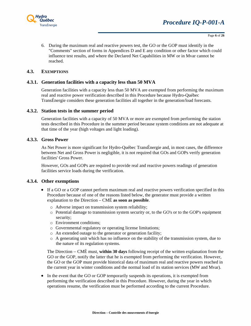
5.1.1. Generating stations connected to the Hydro-Québec TransÉnergie transmission system
Reference – Process A1 in Appendix A
1. The GO or the GOP must send its testing request as an outage request, and include its testing procedure with it. The outage request is submitted to the Regional Outage Scheduler for its area.
In scheduling the test, the GO or the GOP takes such facility-specific factors into account (e.g., time of local ice cover formation).
The GO or the GOP must complete test scheduling before noon, at least 4 working days before the test date.
2. The Regional Outage Scheduler analyzes the request in terms of its impact on regional transmission system reliability.
a. If regional transmission system reliability and transmission equipment security are not compromised, the Scheduler forwards the request to the System Control Outage Scheduler. The latter studies the request in terms of the main transmission system. The request will be approved, provided that reliability of the main transmission system is not compromised.
b. Should either the Regional Outage Scheduler or the System Control Outage Scheduler refuse the request, the GO or the GOP representative will be informed and given the reasons for the refusal.
In the event of refusal, the Regional Outage Scheduler will propose a new date for performing the test to the GO or the GOP representative.
Direction – Contrôle des mouvements d'énergie

HI
Procedure IQ-P-001-A
Page 8 of 26
5.1.2. Generating stations connected to an auxiliary transmission system and for the Churchill Falls Generating Station
Reference – Process A2 in Appendix A
1. The GO or the GOP must send its testing request as an outage request, and include its testing procedure with it. The outage request is submitted to the System Control Outage Scheduler.
In scheduling the test, the GO or the GOP takes such facility-specific factors into account (e.g., time of local ice cover formation).
The GO or the GOP must complete test scheduling before noon, at least 4 working days before the test date.
2. The System Control Outage Scheduler analyzes the request received from GO or GOP in terms of the main transmission system.
a. Provided that reliability of the main transmission system is not compromised, the request is approved.
b. Should the request be refused, the GO or the GOP representative is so informed and given the reasons for the refusal.
In the event of refusal, the System Control Outage Scheduler will propose a new date for performing the test to the GO or the GOP representative.
5.2. CONDUCTING THE TESTS
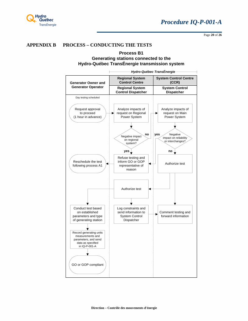
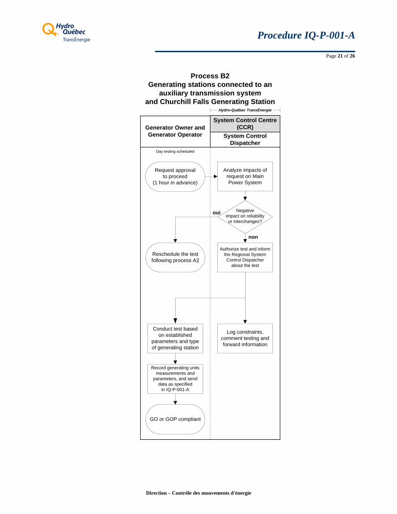
Reference – Process B1 and B2 in Appendix B
5.2.1. Communications before and during the test
Note: The communications before and during the test for the Hydro-Saguenay Generating Stations have special features. Please refer to the test conducting process described in Appendix C of the current Procedure for more details.
5.2.1.1. Generating stations connected to the Hydro-Québec TransÉnergie transmission system
1 hour prior to the test
1. On the day of testing, one hour before testing is to begin, the GO or the GOP representative contacts the Regional System Control Dispatcher to ask him to authorize the test.
2. The Regional System Control Dispatcher analyzes the impact of testing on regional transmission system reliability. Provided that testing does not compromise regional transmission system reliability, the Regional System Control Dispatcher asks the System Control Dispatcher to authorize the test.
If it does compromise reliability, the Regional System Control Dispatcher cancels the test and informs the GO or the GOP representative of the reasons for doing so. The latter must then reschedule the test as set out in section 5.1.1.
Direction – Contrôle des mouvements d'énergie

HI
Procedure IQ-P-001-A
Page 9 of 26
3. The System Control Dispatcher analyzes the impact that testing will have on main transmission system reliability. Provided that the request does not compromise main transmission system reliability and has no major effect on interchange schedules, the Dispatcher authorizes the Regional System Control Dispatcher to proceed. The Regional System Control Dispatcher contacts the GO or the GOP representative to ensure that testing begins on schedule.
If testing does compromise reliability of the main transmission system, the System Control Dispatcher so notifies the Regional System Control Dispatcher. The Regional System Control Dispatcher informs the GO or the GOP representative, who must then reschedule the test as set out in section 5.1.1. The reasons for denying the test are also given to the GO or the GOP representative.
At the beginning of the test
At the scheduled time of testing or the time specified by the Regional System Control Dispatcher, the latter asks the GO or the GOP representative at the generating station to perform the test following standard procedures. The Regional System Control Dispatcher must notify the System Control Dispatcher of the exact time testing will start.
During the testing
The designated operator of the generating station notes any unusual situation arising during the testing and sends that information to the Regional System Control Dispatcher, who records it.
5.2.1.2. Generating stations connected to an auxiliary transmission system and for the Churchill Falls Generating Station
1 hour prior to the test
1. On the day of testing, one hour before testing is to begin, the GO or the GOP representative contacts the System Control Dispatcher to ask that the test be authorized.
2. The System Control Dispatcher analyzes the impact that testing will have on main transmission system reliability. Provided that the request does not compromise main transmission system reliability and has no major effect on interchange schedules, the Dispatcher authorizes the GO or the GOP representative to proceed.
If testing does compromise reliability of the main transmission system, the System Control Dispatcher notifies the GO or the GOP representative to that effect. The latter must then reschedule the test as set out in section 5.1.2. The reasons for denying the test are given to the GO or the GOP representative.
At the beginning of the test
At the scheduled time of test or the time specified by the System Control Dispatcher, the latter asks the GO or the GOP representative at the generating station to perform the test following standard procedures. The GO or the GOP representative must notify the System Control Dispatcher of the exact time testing will start.
During the testing
The designated operator of the generating station notes any unusual situation arising during the testing and sends that information to the System Control Dispatcher, who records it.
Direction – Contrôle des mouvements d'énergie

HI
Procedure IQ-P-001-A
Page 10 of 26
5.2.2. Framework test procedures
5.2.2.1. STATION TEST – Maximum real and reactive power of a generating station
For hydroelectric generating stations, thermal plants and gas-fired plants, the station test lasts at least 1 hour 15 minutes and consists of the following steps:
1. For a minimum duration of 1 hour, test the maximum real power of the generating station (all generating units simultaneously) accounting for the reactive power (Mvar) required by the state of the power system at the time of testing.
2. For the first 15 minutes of the second hour, maintain the state described in step 1, then check the reactive power (Mvar) developed by raising the generator output voltage setpoint until the limit for one of the following is reached:
o generator output voltage; o transmission system voltage; o stator current or rotor current.
Given the impact of this testing method on regional transmission systems, it must be coordinated with Hydro-Québec TransÉnergie staff.
5.2.2.2. UNIT TEST – Maximum real and reactive power of each unit at a generating station
The purpose of the unit test is to check the electrical characteristics of generating units. Two types of tests are designed to determine the characteristic curve (P-Q curve) of a generating unit at the generating unit’s maximum real power (MW).
1. Unit test of reactive power produced (lagging test)
For the hydroelectric generating stations, thermal plants and gas-fired plants, the Generator Operator increases the generating unit’s real power to its maximum, then checks:
For a minimum duration of 1 hour (or until the temperature stabilizes), the reactive power (Mvar) developed by raising the generator output voltage setpoint until the stator current limit or rotor current limit is reached.
2. Unit test of reactive power absorbed (leading test)
Once the unit test for the production of reactive power is completed, the Generator Operator must keep the generating unit at its maximum real power (MW) and check:
For a minimum duration of 15 minutes, the reactive power (Mvar) obtained by lowering the generator output voltage setpoint until the stator current limit or polar angle limiter has been reached.
Direction – Contrôle des mouvements d'énergie

HI
Procedure IQ-P-001-A
Page 11 of 26
5.2.3. Retesting
The test must be performed again at a different time if the state of the power system at the time of testing does not allow one of the following limits to be reached: generator output voltage, stator current or rotor current.
5.2.4. After testing
When testing ends, the designated operator of the generating station must notify the Regional System Control Dispatcher or System Control Dispatcher of any restriction, constraint or alarm that occurred during the test and was related to the equipment tested, as the case may be. The Regional System Control Dispatcher, for generating stations connected to the Hydro-Québec TransÉnergie transmission system (excluding Churchill Falls Generating Station), records this information and forwards it to the System Control Dispatcher.
When testing ends, the Regional System Control Dispatcher, after receiving instructions from the System Control Dispatcher, directs the designated operator of the generating station to adjust generation to the scheduled value or another value, depending on the state of the power system at that time. For generating stations connected to an auxiliary transmission system or for the Churchill Falls Generating Station, the System Control Dispatcher directs the Generator Operator to set the generation at the scheduled level.
Note: The end of testing for the Hydro-Saguenay Generating Stations has special features. Please refer to the test conducting process described in Appendix C of the current Procedure for more details.
5.3. COMMUNICATING RESULTS
The GO or the GOP must send the compiled test results to the Direction – CMÉ:
Every year and no later than April 1st for station tests conducted during the previous winter period, that is from November 1st to February 28th.
Every year and no later than January 31st for unit tests conducted between January 1st and December 31st of the previous year.
Furthermore, the GO or the GOP is in charge of recording the test results. To do so, the forms in Appendices D and E must be used. However, a different form format which contains at least the information requested in Appendices D and E may be used.
5.4. DISCREPANCIES IN RESULTS
If the difference between the results of station tests or unit tests and the Declared Capability (i.e. calculated theoretical values established using the parameters provided by the GO or the GOP for this generating station in conditions similar to the test conditions) is 4% or more, an explanation must be given to the Direction – CMÉ by the GO or the GOP within 30 days following transmission of the compiled test results. In addition, the GO or the GOP must provide a list of measures to address the discrepancies.
As required, the GO or the GOP will have to update parameters provided for this generating station. If the GO or the GOP is not able to explain the discrepancy, the GO or the GOP will have to retest.
Direction – Contrôle des mouvements d'énergie

HI
Procedure IQ-P-001-A
Page 12 of 26
6. TEST PROCEDURE – WIND FARMS
6.1. VERIFICATION METHOD
The verification method for wind farms consists of providing performance data recorded under normal operating conditions at the connecting point, as described in Appendix F. The following data must be supplied:
Maximum real power output (10 minutes average MW) obtained in the current year, date, hour and horizontal wind speed (10 minutes average from the highest captor) at the connecting point.
For wind farms equipped with a secondary voltage control (included in Wind Farm Manager Systems), the following data are also required:
Maximum reactive power output and maximum reactive power absorbed (10 minutes average Mvar) obtained in the current year, date, hour and horizontal wind speed (10 minutes average from the highest captor) at the connecting point.
6.2. COMMUNICATING RESULTS
Performance data of wind farms must be submitted every year to the Direction – CMÉ as soon as available, but no later than January 31st for the period between January 1st and December 31st of the previous year.
The compilation of the performance data must be done by the GO or the GOP in the form supplied in Appendix F of this Procedure. However, a different form format which contains at least the information requested in Appendix F may be used.
6.3. DISCREPANCIES IN RESULTS
If the difference between the performance data of a wind farm and the performance data of the previous year is 4% or more, an explanation must be provided to the Direction – CMÉ by the GO or the GOP within 30 days following transmission of the compiled performance data. Also, the GO or the GOP must provide a list of measures to address the discrepancies.
The GO or the GOP will have to update parameters provided for this wind farm, as required.
Direction – Contrôle des mouvements d'énergie

HI
Procedure IQ-P-001-A
Page 13 of 26
7. INABILITY TO ACHIEVE THE DECLARED CAPABILITIES
At any time, when a generating unit, a generating station or a wind farm cannot achieve the Declared Capability in MW or in Mvar because of equipment issues, the GO or the GOP must notify as soon as possible:
The Regional Outage Scheduler for a generation facility connected to the Hydro-Québec TransÉnergie transmission system;
The System Control Outage Scheduler for a generation facility connected to an auxiliary transmission system or for the Churchill Falls Generating Station.
Moreover, the GO or the GOP must supply an action plan in order to address the discrepancies within 30 days following the detection of a problem.
If the Declared Capability cannot be achieved all the time, the GO or the GOP must:
For hydroelectric generating stations, thermal plants and gas-fired plants, conduct the maximum real and reactive power verification as soon as possible, and send the test results to the Direction – CMÉ within 30 days following the verification;
For wind farms, update parameters of the wind farm concerned.
8. COMMUNICATING RESULTS OF UNIT TESTS TO HYDRO-QUÉBEC TRANSÉNERGIE
The results of unit tests help validate official specifications for generating units provided by GOs or GOPs. These results will be transmitted by the Direction – CMÉ to Hydro-Québec TransÉnergie's unit Planification et stratégies du réseau principal.
Direction – Contrôle des mouvements d'énergie

HI
Procedure IQ-P-001-A
Page 14 of 26
9. CONTACTS
For submitting your results or for any questions related to this Procedure, please write to:
Direction – Contrôle des mouvements d'énergie Complexe Desjardins, tour est, 19e étage C.P. 10000, succ. pl. Desjardins Montréal (Québec) H5B 1H7
Fax: 514 879-4691
System Control Centre (CCR) in Montreal
System Control Dispatchers
514 289-4990 514 289-4991 514 289-4992
Regional Outage Schedulers
Chicoutimi
418 696-3815 or 819-764-5124 ext. 4320 [email protected]
Rouyn-Noranda
819 764-5124 Ext. 4326, 4313 or 4378 [email protected]
Baie-Comeau
1 866 561-5697 Ext. 3909 [email protected].
Québec
1 866 561-5697 Ext. 3906, 3908 or [email protected]
Trois-Rivières
819 694-2432, 819 694-2508, 819 694-2600, 819 694-2543 or 819 694-2422 [email protected]
Montréal
1 866 604-4041 Ext. 3904, 3905, 3906, 3907 or 3908 [email protected]
Saint-Jérôme
1 866 604-4041 Ext. 3901, 3902, 3903 [email protected]
System Control Outage Schedulers
Montréal
Fax:
514 289-4364, 514 289-3845 or 514 289-5998 514 [email protected]
Note: To contact the Regional System Control Dispatchers, please refer to the telephone numbers indicated in the Common System Operating Instructions.
Direction – Contrôle des mouvements d'énergie

HI
Procedure IQ-P-001-A
Page 15 of 26
10. HISTORY OF UPDATES
Date Modification Reason
2005-10-21 Initial effective date New procedure
2007-10-26 Modification to most sections, to all Appendices and to all processes;
Sections 7 and 9 added;
Sub-sections 5.4 and 6.1.1 added;
Process 1B and 2B added;
Appendix C added.
Control Areas are now called Balancing Authority Areas;
Administrative changes in Hydro-Québec TransÉnergie;
Compliance with NPCC A-13 Criteria;
Standardization of vocabulary used (French version only).
2008-10-14 Minor modifications to most sections, to processes and to Appendices in order to clarify certain points;
Section 3, addition of a reference: Reliability Coordinator Code of Conduct;
Section 4.4.4, addition of a exemption condition when a Generator Owner suspends operations;
Appendices A and B: consider status of the stabilizers and of the voltage regulator during the tests;
Section 9, deletion of the telephone numbers of the Regional System Control Dispatchers and addition of a note.
Updates;
New phone system in the Regional System Control Centres for the Regional System Control Dispatchers.
2009-10-16 Modifications, sections 2, 4.3.4, 5.4, 6.3, and 7, and Appendices E, F and G;
Modification, Purpose;
Reorganization of section 4;
Section 4.2.2: modification of the deadlines for submitting the schedule and distinction between station and unit tests;
Modification: sections 4.2.3 and 5.2.2.1;
Modifications: sections 5.1 and 5.2.1;
Update of the compliance; new NPCC Directories D9 and D10 and Criteria A-03 cancelled;
Addition of the verification method for wind farms;
Make a distinction between the verification conditions of the generating stations and the wind farms;
Accuracy concerning the global test schedule;
For hydroelectric generating stations and thermal plants, the minimum duration of the station test is 1 h 15 instead of 2 h;
For all generating stations, the minimum unit test duration is 1 h 15;
Separate the procedures for generating stations connected to the HQT system and for the generating stations connected to a private system (including the Churchill Falls Generating Station);
Direction – Contrôle des mouvements d'énergie

HI
Procedure IQ-P-001-A
Page 16 of 26
Date Modification Reason
2009-10-16 Sections 5.3 and 6.2: modification of the deadlines for submitting the test results and the performance data;
Sections 4.2.4, 5.3 and 6.2: use the supplied forms for compiling the test results or the performance data;
Modification of the procedure title;
Section 8: removal of contact information for the Senior Agent – System Operations;
Appendices A and B: modification of how processes are numbered and removal of columns and notes;
Addition of Appendices C and D and reference to these appendices in the main text.
Reduce the number of test result reports submitted per year for the generating stations and grant an extension for the wind farms;
Standardization of the data submitted;
Update;
Describe the special features of test scheduling and test conducting for the Hydro-Saguenay Generating Stations and Chats Falls Generating Station.
2010-10-18 This procedure also applies to Generator Operators;
Direction "Contrôle des mouvements d'énergie" is now "Contrôle et exploitation du réseau";
Section 2: modification;
Section 4.2.2: station test must be conducted every 3 years instead of every year;
Section 4.2.3: unit test must be conducted every 6 years instead of every 5 years;
Sections 4.2.2 and 4.2.3: the schedules must be also sent to Direction DCER;
Section 4.2.5: new section "Waiver request for conducting the station test";
Section 8: modification of contact information (phone numbers);
Appendices A and B: update of the processes;
The Appendix titled "Chats Falls Generating Station – Particular process for scheduling and conducting the tests" has been removed from this document.
Update of the compliance according to NERC Standard TOP-002-2a;
Update;
Update of the compliance;
New requirements;
Allow the station test to be conducted outside the winter period under certain conditions;
Update;
It is no longer necessary to conduct tests at the Chats Falls Generating Station because this facility is located in the Ontario Balancing Authority Area.
Direction – Contrôle des mouvements d'énergie

HI
Procedure IQ-P-001-A
Page 17 of 26
Direction – Contrôle des mouvements d'énergie
Date Modification Reason
2014-05-09 Direction "Contrôle et exploitation du réseau" is now "Contrôle des mouvements d'énergie";
Section 2: modifications;
Section 4.2.3: unit test must be conducted every 5 years, instead of every 6 years;
Section 4.2.6: article 2, addition;
Section 4.3.4: modifications;
Section 6.1: modifications;
Section 7: modifications;
Section 8: new article;
Section 9: modifications;
Appendix C: the company is now named Produits forestiers Résolu;
Appendix F: modifications.
Update;
Update of the compliance; Addition, VAR-001-3;
New requirement;
Addition of an operating criterion;
Addition of reasons for an exemption;
Modification of performance data to be submitted;
An action plan must be supplied within 30 days following the detection of a problem;
Transmission of unit test results to HQT;
Update;
Update;
Update in accordance with section 6.1 and request for additional information.
HI
Procedure IQ-P-001-A
Page 18 of 26
APPENDIX A PROCESS – SCHEDULING THE TESTS
Direction – Contrôle des mouvements d'énergie

HI
Procedure IQ-P-001-A
Page 19 of 26
Direction – Contrôle des mouvements d'énergie
HI
Procedure IQ-P-001-A
Page 20 of 26
APPENDIX B PROCESS – CONDUCTING THE TESTS
System Control Dispatcher
Regional SystemControl Dispatcher
Generator Owner andGenerator Operator
Day testing scheduled
Analyze impacts of request on MainPower System
Analyze impacts of request on Regional
Power System
Negative impacton regional
system?
Negativeimpact on reliability or interchanges?
Regional SystemControl Centre
System Control Centre(CCR)
no
yes
yes
no
Refuse testing and inform GO or GOPrepresentative of
reason
Reschedule the test following process A1 Authorize test
GO or GOP compliant
Authorize test
Conduct test basedon established
parameters and type of generating station
Log constraints and send information to
System Control Dispatcher
Comment testing and forward information
Record generating units measurements and
parameters, and send data as specified
in IQ-P-001-A
Process B1Generating stations connected to the
Hydro-Québec TransÉnergie transmission system
Request approvalto proceed
(1 hour in advance)
Hydro-Québec TransÉnergie
Direction – Contrôle des mouvements d'énergie
HI
Procedure IQ-P-001-A
Page 21 of 26
System Control Dispatcher
Generator Owner andGenerator Operator
Request approvalto proceed
(1 hour in advance)
Day testing scheduled
Analyze impacts of request on MainPower System
Negativeimpact on reliability or interchanges?
System Control Centre(CCR)
oui
non
Reschedule the test following process A2
Authorize test and informthe Regional System Control Dispatcher
about the test
GO or GOP compliant
Hydro-Québec TransÉnergie
Conduct test basedon established
parameters and type of generating station
Log constraints, comment testing and forward information
Record generating units measurements and
parameters, and send data as specified
in IQ-P-001-A
Process B2Generating stations connected to an
auxiliary transmission systemand Churchill Falls Generating Station
Direction – Contrôle des mouvements d'énergie

HI
Procedure IQ-P-001-A
Page 22 of 26
APPENDIX C HYDRO-SAGUENAY GENERATING STATIONS – PARTICULAR PROCESS FOR SCHEDULING AND CONDUCTING THE TESTS
The power system of the Produits forestiers Résolu Company (Hydro-Saguenay division) is connected to the auxiliary transmission system of Rio Tinto Alcan (RTA), but it is commercially fed by Hydro-Québec. Because of this unusual feature, scheduling and conducting the tests must be done in the way described below.
Scheduling the test
1. Hydro-Saguenay must send its testing request as an outage request, and include its testing procedure with it. The outage request is submitted to the RTA – Outage Scheduler. The latter sends a copy of this outage request to the Regional Outage Scheduler (Regional Operations at Chicoutimi) and to the System Control Outage Scheduler.
In scheduling the test, Hydro-Saguenay takes facility-specific factors into account (e.g., ice cover formation period).
Hydro-Saguenay must complete test scheduling before noon, at least 4 working days before the test date.
2. The RTA – Outage Scheduler analyzes the request received from Hydro-Saguenay in terms of its impact on his transmission system reliability.
a. Provided that reliability of the transmission system is not compromised, the request is approved.
b. Should the request be refused, Hydro-Saguenay is informed and given the reasons for the refusal. Furthermore, the RTA – Outage Scheduler will propose a new date for performing the test to Hydro-Saguenay.
The RTA – Outage Scheduler also communicates the decision to the Regional Outage Scheduler (Regional Operations at Chicoutimi) and to the System Control Outage Scheduler.
Conducting the test – Communications before and during the test
1 hour prior to the test
1. On the day of testing, one hour before testing is to begin, Hydro-Saguenay contacts the RTA – System Control Dispatcher to ask him to authorize the test.
2. The RTA – System Control Dispatcher analyzes the impact that testing will have on RTA transmission system reliability. Provided the request does not compromise transmission system reliability, Hydro-Saguenay will be authorized to proceed.
If testing does compromise reliability, the RTA – System Control Dispatcher notifies Hydro-Saguenay to that effect. The latter must then reschedule the test as set out in the previous section. The reasons for denying the test are given to Hydro-Saguenay.
The RTA – System Control Dispatcher also communicates his decision to the Regional System Control Dispatcher (Regional Operations at Chicoutimi) and to the System Control Dispatcher.
Direction – Contrôle des mouvements d'énergie

HI
Procedure IQ-P-001-A
Page 23 of 26
Direction – Contrôle des mouvements d'énergie
At the beginning of the test
At the scheduled time of testing or the time specified by the RTA – System Control Dispatcher, the latter asks the Hydro-Saguenay to perform the test following standard procedures. The RTA – System Control Dispatcher must notify the Regional System Control Dispatcher (Regional Operations at Chicoutimi) and the System Control Dispatcher of the exact time of the test will start.
During the testing
Hydro-Saguenay notes any unusual situation arising during the testing and sends that information to the RTA – System Control Dispatcher, who records it.
After testing
When testing ends, Hydro-Saguenay must notify the RTA – System Control Dispatcher of any restriction, constraint or alarm that occurred during the test and was related to the equipment tested. The RTA – System Control Dispatcher records this information and forwards it to the Regional System Control Dispatcher (Regional Operations at Chicoutimi) and the System Control Dispatcher
Note: Communicating results must be done according to section 5.3 of the current Procedure.

HI Procedure IQ-P-001-A
Page 24 of 26
Direction – Contrôle des mouvements d'énergie
APPENDIX D STATION TEST – MAXIMUM REAL AND REACTIVE POWER VERIFICATION
Test date (yyyy-mm-dd): [ - - ]
Generating station Station service load
Time Total Output Water temp.1 (hydro generating
station)
Air temp. 2 Upstream level
Down-stream level
Comments
(MW) (Mvar) (° C) (° C) (m) (m)
MW: Start:
Mvar: End:
DECLARED CAPABILITY
G.O.3 Stabilizers Voltage regulator
UNITS
(MW) (Mvar)
MW Mvar kV
(%) (ON/OFF) (auto/manual)
Comments
Start:
After 1 h of testing:
After 1 h 15 of testing:
Start:
After 1 h of testing:
After 1 h 15 of testing:
Start:
After 1 h of testing:
After 1 h 15 of testing:
Start:
After 1 h of testing:
After 1 h 15 of testing:
1 Water temperature: temperature of cool water at the generator cooling system intake 2 Air temperature: temperature of cool air at the cooling system outlet or generator rotor intake 3 G.O.: Gate opening By: ______________________________________ Company: _____________________________________ Compiling Date: _____________________
Email: ______________________________________ Phone: _____________________________________

HI Procedure IQ-P-001-A
Page 25 of 26
Direction – Contrôle des mouvements d'énergie
APPENDIX E UNIT TEST – MAXIMUM REAL AND REACTIVE POWER VERIFICATION
Test date (yyyy-mm-dd): [ - - ]
Generating station Station service load
Time Total Output Water temp.1 (hydro generating
station)
Air temp. 2 Upstream level
Down-stream level
Comments
(MW) (Mvar) (° C) (° C) (m) (m)
MW: Start:
Mvar: End:
DECLARED CAPABILITY
G.O.3 Stabilizers Voltage regulator
UNITS
(MW) (Mvar)
MW Mvar kV
(%) (ON/OFF) (auto/manual)
Comments
Start:
End:
Leading test4:
Start:
End:
Leading test4:
Start:
End:
Leading test4:
Start:
End:
Leading test4:
1 Water temperature: temperature of cool water at the generator cooling system intake 2 Air temperature: temperature of cool air at the cooling system outlet or generator rotor intake 3 G.O.: Gate opening 4 For specified generating stations only By: ______________________________________ Company: _____________________________________ Compiling Date: _____________________
Email: ______________________________________ Phone: _____________________________________

HI Procedure IQ-P-001-A
Page 26 of 26
Direction – Contrôle des mouvements d'énergie
APPENDIX F PERFORMANCE DATA FOR WIND FARMS
Wind Farm name: ______________________________________
Wind Generators Description
Hub height Installed capacity by wind generator
Operating range Wind speed
Operating range Outside
Temperature
Manufacturer Model
(m)
Number ofwind
generators
(MW) (Mvar)
Power factor
(m/s) (°C)
Comments
Description of Reactive Power Compensation System
Maximal absorbed
Maximal output
Operating range Active power
Operating range Temperature
Manufacturer Model Technology Number
(Mvar) (Mvar) (MW) (°C)
Comments
Wind Farm Performance Data Date of collect data from (aaaa-mm-jj): [ - - ] to [ - - ]
Wind Farm Generation Date Time Number ofwind
generators
Total Output Outside Temperature
Wind speed
Station service load
(MW or Mvar) (°C) (m/s) (MW) (Mvar)
Maximum – MW
Maximum absorbed – Mvar PERFORMANCE DATA
Maximum output – Mvar
Wind Farm Generation Total Output Annual Capacity Factor (MW or Mvar) (%)
Maximum – MW
Maximum absorbed – Mvar DECLARED
CAPABILITY Maximum output – Mvar
By: ______________________________________ Company: _____________________________________ Compiling Date: _____________________
Email: ______________________________________ Phone: _____________________________________

![CartemotoneigeSagLac2014-15 [Unlocked by ] sentier lac st-jean.pdf · 6.6 trans-quÉbec 83 trans-quÉbec 93 trans-quÉbec 93 trans-quÉbec 93 trans-quÉbec 93 trans-quÉbec 93 trans-quÉbec](https://img.pdfslide.us/doc/110x75/5b2cb5eb7f8b9ac06e8b5a01/cartemotoneigesaglac2014-15-unlocked-by-sentier-lac-st-jeanpdf-66-trans-quebec.jpg)